US9020432B2 - Mobile communication device, communication method, integrated circuit, and program - Google Patents
Mobile communication device, communication method, integrated circuit, and program Download PDFInfo
- Publication number
- US9020432B2 US9020432B2 US13/203,772 US201013203772A US9020432B2 US 9020432 B2 US9020432 B2 US 9020432B2 US 201013203772 A US201013203772 A US 201013203772A US 9020432 B2 US9020432 B2 US 9020432B2
- Authority
- US
- United States
- Prior art keywords
- information
- appliance
- server
- communication device
- image
- Prior art date
- Legal status (The legal status is an assumption and is not a legal conclusion. Google has not performed a legal analysis and makes no representation as to the accuracy of the status listed.)
- Active, expires
Links
- 238000004891 communication Methods 0.000 title claims abstract description 1107
- 238000010295 mobile communication Methods 0.000 title claims abstract description 169
- 238000000034 method Methods 0.000 title claims description 166
- 230000005540 biological transmission Effects 0.000 claims abstract description 236
- 238000003860 storage Methods 0.000 claims description 71
- 238000001514 detection method Methods 0.000 claims description 56
- 230000033001 locomotion Effects 0.000 claims description 53
- 230000001133 acceleration Effects 0.000 claims description 39
- 238000004590 computer program Methods 0.000 claims description 5
- 239000000047 product Substances 0.000 description 504
- 238000012545 processing Methods 0.000 description 467
- 238000010586 diagram Methods 0.000 description 171
- 230000006870 function Effects 0.000 description 150
- 238000007726 management method Methods 0.000 description 120
- 230000004044 response Effects 0.000 description 111
- 102220511583 Kappa-casein_N10A_mutation Human genes 0.000 description 87
- 238000012546 transfer Methods 0.000 description 60
- 238000009434 installation Methods 0.000 description 42
- 238000004519 manufacturing process Methods 0.000 description 34
- 102200128633 rs104893843 Human genes 0.000 description 31
- 238000012937 correction Methods 0.000 description 27
- 238000009826 distribution Methods 0.000 description 25
- 230000008569 process Effects 0.000 description 24
- 230000008859 change Effects 0.000 description 20
- 238000004364 calculation method Methods 0.000 description 19
- 238000007639 printing Methods 0.000 description 19
- 230000010365 information processing Effects 0.000 description 17
- 238000005516 engineering process Methods 0.000 description 14
- 238000004806 packaging method and process Methods 0.000 description 12
- 230000008901 benefit Effects 0.000 description 11
- 239000000284 extract Substances 0.000 description 11
- 230000003287 optical effect Effects 0.000 description 10
- 230000004913 activation Effects 0.000 description 9
- 230000000694 effects Effects 0.000 description 7
- 239000000463 material Substances 0.000 description 7
- 239000004973 liquid crystal related substance Substances 0.000 description 6
- 238000012913 prioritisation Methods 0.000 description 6
- 230000009471 action Effects 0.000 description 5
- 235000013305 food Nutrition 0.000 description 5
- CURLTUGMZLYLDI-UHFFFAOYSA-N Carbon dioxide Chemical compound O=C=O CURLTUGMZLYLDI-UHFFFAOYSA-N 0.000 description 4
- 238000012986 modification Methods 0.000 description 4
- 230000004048 modification Effects 0.000 description 4
- 239000004065 semiconductor Substances 0.000 description 4
- 238000005406 washing Methods 0.000 description 4
- 102220580465 Thioredoxin domain-containing protein 11_N13A_mutation Human genes 0.000 description 3
- 238000004422 calculation algorithm Methods 0.000 description 3
- 238000007796 conventional method Methods 0.000 description 3
- 238000013500 data storage Methods 0.000 description 3
- 230000007423 decrease Effects 0.000 description 3
- 230000009977 dual effect Effects 0.000 description 3
- 230000006872 improvement Effects 0.000 description 3
- 230000010354 integration Effects 0.000 description 3
- 238000005259 measurement Methods 0.000 description 3
- 230000009467 reduction Effects 0.000 description 3
- 102220078268 rs140308307 Human genes 0.000 description 3
- 230000001360 synchronised effect Effects 0.000 description 3
- 241001025261 Neoraja caerulea Species 0.000 description 2
- 241000209094 Oryza Species 0.000 description 2
- 235000007164 Oryza sativa Nutrition 0.000 description 2
- 229910002092 carbon dioxide Inorganic materials 0.000 description 2
- 239000001569 carbon dioxide Substances 0.000 description 2
- 238000001816 cooling Methods 0.000 description 2
- 238000013461 design Methods 0.000 description 2
- 238000011161 development Methods 0.000 description 2
- 230000018109 developmental process Effects 0.000 description 2
- 230000007274 generation of a signal involved in cell-cell signaling Effects 0.000 description 2
- 238000010438 heat treatment Methods 0.000 description 2
- 238000005457 optimization Methods 0.000 description 2
- 230000010363 phase shift Effects 0.000 description 2
- 238000010248 power generation Methods 0.000 description 2
- 238000007781 pre-processing Methods 0.000 description 2
- 238000003825 pressing Methods 0.000 description 2
- 235000009566 rice Nutrition 0.000 description 2
- 230000008054 signal transmission Effects 0.000 description 2
- 239000013589 supplement Substances 0.000 description 2
- XLYOFNOQVPJJNP-UHFFFAOYSA-N water Substances O XLYOFNOQVPJJNP-UHFFFAOYSA-N 0.000 description 2
- 230000032683 aging Effects 0.000 description 1
- 238000004887 air purification Methods 0.000 description 1
- 238000004458 analytical method Methods 0.000 description 1
- 230000000903 blocking effect Effects 0.000 description 1
- 102220515765 cAMP-dependent protein kinase inhibitor alpha_N10D_mutation Human genes 0.000 description 1
- 238000006243 chemical reaction Methods 0.000 description 1
- 230000000052 comparative effect Effects 0.000 description 1
- 230000006866 deterioration Effects 0.000 description 1
- 230000005674 electromagnetic induction Effects 0.000 description 1
- 230000005764 inhibitory process Effects 0.000 description 1
- 238000003780 insertion Methods 0.000 description 1
- 230000037431 insertion Effects 0.000 description 1
- 230000007774 longterm Effects 0.000 description 1
- 238000012423 maintenance Methods 0.000 description 1
- 238000013507 mapping Methods 0.000 description 1
- 239000002184 metal Substances 0.000 description 1
- 230000002093 peripheral effect Effects 0.000 description 1
- 230000000717 retained effect Effects 0.000 description 1
- 102220069125 rs77384282 Human genes 0.000 description 1
- 238000010079 rubber tapping Methods 0.000 description 1
- 230000005236 sound signal Effects 0.000 description 1
Images


Classifications
-
- H—ELECTRICITY
- H04—ELECTRIC COMMUNICATION TECHNIQUE
- H04L—TRANSMISSION OF DIGITAL INFORMATION, e.g. TELEGRAPHIC COMMUNICATION
- H04L12/00—Data switching networks
- H04L12/28—Data switching networks characterised by path configuration, e.g. LAN [Local Area Networks] or WAN [Wide Area Networks]
- H04L12/40—Bus networks
- H04L12/40006—Architecture of a communication node
- H04L12/40013—Details regarding a bus controller
-
- G—PHYSICS
- G08—SIGNALLING
- G08C—TRANSMISSION SYSTEMS FOR MEASURED VALUES, CONTROL OR SIMILAR SIGNALS
- G08C17/00—Arrangements for transmitting signals characterised by the use of a wireless electrical link
- G08C17/02—Arrangements for transmitting signals characterised by the use of a wireless electrical link using a radio link
-
- H04W4/008—
-
- H—ELECTRICITY
- H04—ELECTRIC COMMUNICATION TECHNIQUE
- H04W—WIRELESS COMMUNICATION NETWORKS
- H04W4/00—Services specially adapted for wireless communication networks; Facilities therefor
- H04W4/80—Services using short range communication, e.g. near-field communication [NFC], radio-frequency identification [RFID] or low energy communication
-
- G—PHYSICS
- G08—SIGNALLING
- G08C—TRANSMISSION SYSTEMS FOR MEASURED VALUES, CONTROL OR SIMILAR SIGNALS
- G08C2201/00—Transmission systems of control signals via wireless link
- G08C2201/20—Binding and programming of remote control devices
-
- G—PHYSICS
- G08—SIGNALLING
- G08C—TRANSMISSION SYSTEMS FOR MEASURED VALUES, CONTROL OR SIMILAR SIGNALS
- G08C2201/00—Transmission systems of control signals via wireless link
- G08C2201/30—User interface
- G08C2201/32—Remote control based on movements, attitude of remote control device
-
- G—PHYSICS
- G08—SIGNALLING
- G08C—TRANSMISSION SYSTEMS FOR MEASURED VALUES, CONTROL OR SIMILAR SIGNALS
- G08C2201/00—Transmission systems of control signals via wireless link
- G08C2201/90—Additional features
- G08C2201/91—Remote control based on location and proximity
-
- G—PHYSICS
- G08—SIGNALLING
- G08C—TRANSMISSION SYSTEMS FOR MEASURED VALUES, CONTROL OR SIMILAR SIGNALS
- G08C2201/00—Transmission systems of control signals via wireless link
- G08C2201/90—Additional features
- G08C2201/93—Remote control using other portable devices, e.g. mobile phone, PDA, laptop
-
- H—ELECTRICITY
- H04—ELECTRIC COMMUNICATION TECHNIQUE
- H04B—TRANSMISSION
- H04B5/00—Near-field transmission systems, e.g. inductive loop type
- H04B5/0056—Near-field transmission systems, e.g. inductive loop type for use in interrogation, identification or read/write systems
- H04B5/0062—Near-field transmission systems, e.g. inductive loop type for use in interrogation, identification or read/write systems in RFID [Radio Frequency Identification] Systems
-
- H04B5/77—
-
- H—ELECTRICITY
- H04—ELECTRIC COMMUNICATION TECHNIQUE
- H04W—WIRELESS COMMUNICATION NETWORKS
- H04W64/00—Locating users or terminals or network equipment for network management purposes, e.g. mobility management
- H04W64/003—Locating users or terminals or network equipment for network management purposes, e.g. mobility management locating network equipment
Definitions
- the present invention relates to a mobile communication device that includes a reader/writer of proximity wireless communication and a general-purpose communication means.
- the present invention also relates to a mobile communication device that includes a reader/writer of proximity wireless communication and a general-purpose communication means and facilitates setting in a home network.
- HEMS Home Energy Management System
- proximity wireless communication is widely employed in devices such as mobile phones, and technological development for facilitating mail address forwarding and the like is underway.
- PTL 1 discloses a method of facilitating input for setting access to a content server, through the use of the proximity wireless communication technology.
- the method disclosed in PTL 1 is a method (system) that saves the user from having to input a URL of a content server to be accessed by a mobile phone, by transferring a unique number of a terminal and a URL of a redirect server to the mobile phone by proximity wireless communication.
- PTL 2 discloses a method whereby information of a cargo is received from a proximity wireless device attached to the cargo and at the same time geographical position information is received from Global Positioning System (GPS), to automatically communicate the geographical position information of the cargo to a server. This method (system) saves the user from having to input these information.
- GPS Global Positioning System
- proximity wireless communication may be effectively used to facilitate setting.
- the user demands a communication device capable of completing setting necessary for a home network without a complex operation.
- the present invention has an object of providing a mobile communication device that can facilitate setting in a home network.
- the present invention also has an object of providing a device that enables, by a simple operation, transmission of predetermined transmission information to a predetermined server when an appliance such as a home appliance is installed in a home (see a home 99 in FIG. 165 ).
- the present invention also has an object of providing a device that can, as a result of the above simple operation, simplify an operation when a wireless LAN access point (see an access point 99 c in FIG. 165 ) or the like performs suitable wireless communication corresponding to an installation position, from among first wireless communication in a first mode (e.g. wireless communication with relatively low power) and second wireless communication in a second mode (wireless communication with relatively high power).
- a wireless LAN access point see an access point 99 c in FIG. 165
- suitable wireless communication corresponding to an installation position from among first wireless communication in a first mode (e.g. wireless communication with relatively low power) and second wireless communication in a second mode (wireless communication with relatively high power).
- the present invention is a mobile communication device including: an appliance information obtainment unit that obtains, from an appliance installed at a predetermined position (e.g. inside a home), appliance information by proximity wireless communication between the installed appliance and the mobile communication device, the appliance information specifying the appliance from among a plurality of appliances; a position information obtainment unit that obtains position information indicating a position of the mobile communication device when the proximity wireless communication is performed between the installed appliance and the mobile communication device; and a transmission unit that transmits transmission information to a predetermined server in the case where the proximity wireless communication is performed, the transmission information including the appliance information obtained by the proximity wireless communication and the obtained position information.
- a predetermined position e.g. inside a home
- a position information obtainment unit that obtains position information indicating a position of the mobile communication device when the proximity wireless communication is performed between the installed appliance and the mobile communication device
- a transmission unit that transmits transmission information to a predetermined server in the case where the proximity wireless communication is performed, the transmission information including the appliance information obtained by the proximity wireless
- “when the proximity wireless communication is performed” means that the proximity wireless communication is performed where the installation position of the appliance (apparatus, device) is the same position as the position of the mobile communication device.
- the same position includes an instance where the installation position of the appliance can be regarded as the same position as the position of the mobile communication device.
- the proximity wireless communication mentioned above is, for example, communication according to Near Field Communication (NFC) when a touching operation of a card for electronic money is performed upon electronic money payment and the like.
- NFC Near Field Communication
- NFC is performed within a distance of several centimeters (e.g. within 2 centimeters or 3 centimeters) upon a touching operation.
- the same position means, for example, that the installation position of the appliance is within several centimeters from the position of the mobile communication device.
- a communication device is, for example, a mobile communication device that reads terminal device information from a terminal device (apparatus, appliance) by proximity wireless communication, and transmits the terminal device information to a server via a general-purpose network
- the mobile communication device including: a terminal device information obtainment unit that obtains the terminal device information from the terminal device by the proximity wireless communication, the terminal device information including at least terminal device identification information for identifying manufacturing information of the terminal device; a communication device information storage unit that stores communication device information including at least communication device identification information for identifying manufacturing information of the communication device; an information adding unit that adds the stored communication device information to the obtained terminal device information, to generate transmission information to be transmitted to the server; and a communication unit that transmits the generated transmission information to the server via the general-purpose network, wherein the communication unit specifies the server based on the terminal device information obtained from the terminal device, and communicates with the specified server.
- the mobile communication device may include: a proximity wireless communication device; and a wired/wireless communication device constituting a home network, wherein a home ID for uniquely identifying a home is added to the terminal device information received by the proximity wireless communication device, and the terminal device information to which the home ID is added is transmitted to the server using the home network communication device.
- position information immediately after the proximity wireless communication is performed with a device, such as a mobile phone, provided with a GPS device or an acceleration sensor may be transmitted to the server as position information of a corresponding home appliance.
- the mobile communication device enables the user to complete setting necessary for a home network, without a complex operation.
- the transmission information can be transmitted by a simple operation such as merely touching the mobile communication device to the installed appliance.
- the device used here is a mobile communication device such as a mobile phone, with there being no need to add a new structure for proximity wireless communication. This contributes to a lower cost.
- the device used here is a mobile communication device, with there being no need to add a new structure for obtainment of position information. This contributes to a sufficiently lower cost. That is, an extent of cost reduction can be increased.
- a very complex operation required to perform suitable wireless communication becomes unnecessary, as a simple operation such as a touching operation is sufficient.
- a significantly simplified operation can be realized.
- FIG. 1 illustrates an entire system of an image capturing device according to Embodiment A1.
- FIG. 2 is an external view of the image capturing device according to Embodiment A1.
- FIG. 3 is a block diagram of the image capturing device according to Embodiment A1.
- FIG. 4 is a block diagram of a second memory in the image capturing device according to Embodiment A1.
- FIG. 5 is a block diagram of the second memory in the image capturing device according to Embodiment A1.
- FIG. 6 is a block diagram of image display method instruction information of the image capturing device according to Embodiment A1.
- FIG. 7 is a flowchart of processing performed by the image capturing device and a TV, according to Embodiment A1.
- FIG. 8 is a flowchart of the processing performed by the image capturing device and the TV, according to Embodiment A1.
- FIG. 9 is a flowchart of the processing performed by the image capturing device and the TV, according to Embodiment A1.
- FIG. 10 is a flowchart of the processing performed by the image capturing device and the TV, according to Embodiment A1.
- FIG. 11 is a flowchart of the processing performed by the image capturing device and the TV, according to Embodiment A1.
- FIG. 12 is a flowchart of the processing performed by the image capturing device and the TV, according to Embodiment A1.
- FIG. 13 is a flowchart of the processing performed by the image capturing device and the TV, according to Embodiment A1.
- FIG. 14 is a flowchart of the processing performed by the image capturing device and the TV, according to Embodiment A1.
- FIG. 15 is a flowchart of the processing performed by the image capturing device and the TV, according to Embodiment A1.
- FIG. 16 is a flowchart of the processing performed by the image capturing device and the TV, according to Embodiment A1.
- FIG. 17 is a flowchart of the processing performed by the image capturing device and the TV, according to Embodiment A1.
- FIG. 18 is a flowchart of the processing performed by the image capturing device and the TV, according to Embodiment A1.
- FIG. 19 is a flowchart of the processing performed by the image capturing device and the TV, according to Embodiment A1.
- FIG. 20 is a flowchart of the processing performed by the image capturing device and the TV, according to Embodiment A1.
- FIG. 21 is a flowchart of the processing performed by the image capturing device and the TV, according to Embodiment A1.
- FIG. 22 is a diagram presenting a display method of the image capturing device and the TV, according to Embodiment A1.
- FIG. 23 is a block diagram of a RF-ID unit in the image capturing device for storing an operation program, a remote controller of the TV, and the TV.
- FIG. 24 is a flowchart of processing for transferring and executing the operation program stored in the RF-ID unit.
- FIG. 25 presents an example of description of the operation program for downloading image and executing slide show.
- FIG. 26 is a block diagram of (a) the TV changing processing of the operation program according to a language code, and (b) a server storing the program.
- FIG. 27 is a flowchart of processing for changing processing of the operation program according to a language code.
- FIG. 28 is a block diagram of a home network 6500 connecting the image capturing device to the TV by a wireless LAN.
- FIG. 29 presents an example of an authentication method without using RF-ID unit.
- FIG. 30 presents an example of an authentication method using RF-ID unit.
- FIG. 31 presents an example of an authentication method used when it is difficult to move a terminal into proximity of another terminal.
- FIG. 32 is a flowchart of an example of processing performed by a camera.
- FIG. 33 is a flowchart of an example of processing performed by the TV.
- FIG. 34 is a block diagram of (a) a first processing unit generating the operation program in the image capturing device to be executed by the TV, and (b) a second memory unit.
- FIG. 35 is a flowchart of processing performed by a program generation unit in the first processing unit.
- FIG. 36 is a flowchart of an example of a program generated by the program generation unit.
- FIG. 37 is a block diagram of (a) the first processing unit generating the operation program in the image capturing device to display a use status of the image capturing device, and (b) the second memory unit.
- FIG. 38 illustrates a use example where the program generated by the image capturing device is executed by an external device (apparatus).
- FIG. 39 is a sequence where the program generated by the image capturing device is executed by a remote controller with display function.
- FIG. 40A is a flowchart of uploading steps in a camera according to Embodiment A2.
- FIG. 40B is a flowchart of uploading steps in the camera according to Embodiment A2.
- FIG. 40C is a flowchart of uploading steps in the camera according to Embodiment A2.
- FIG. 41 is a flowchart of uploading steps in the camera according to Embodiment A2.
- FIG. 42A is a flowchart of uploading steps in the camera according to Embodiment A1.
- FIG. 42B is a flowchart of uploading steps in the camera according to Embodiment A1.
- FIG. 42C is a flowchart of uploading steps in the camera according to Embodiment A1.
- FIG. 42D is a flowchart of uploading steps in the camera according to Embodiment A1.
- FIG. 43 is a flowchart of operation steps of a RF-ID unit in the camera according to Embodiment A2.
- FIG. 44 is a block diagram of a TV according to Embodiment A2.
- FIG. 45 is a flowchart of RF-ID communication between the camera and the TV, according to Embodiment A2.
- FIG. 46A is a flowchart presenting details of FIG. 45 .
- FIG. 46B is a flowchart presenting details of FIG. 45 .
- FIG. 47 presents a data format of the RF-ID communication between the camera and the TV.
- FIG. 48 is a schematic diagram of an electronic catalog display system.
- FIG. 49 is a block diagram of an electronic catalog server information input device.
- FIG. 50 is a flowchart of steps of processing performed by the electronic catalog server information input device.
- FIG. 51 is a block diagram of a RF-ID unit of an electronic catalog notification card.
- FIG. 52 is a block diagram of a TV displaying an electronic catalog.
- FIG. 53 is a block diagram of an electronic catalog server.
- FIG. 54 is a flowchart of steps of processing performed by the electronic catalog server.
- FIG. 55 is a flowchart of steps of processing performed by a TV displaying the electronic catalog.
- FIG. 56 is a diagram illustrating screen display of the electronic catalog.
- FIG. 57 is a table of a data structure of a customer attribute database.
- FIG. 58 is a table of a data structure of an electronic catalog database.
- FIG. 59 is a schematic diagram of a RF-ID-attached post card mailing system.
- FIG. 60 is a block diagram of a TV in the RF-ID-attached post card mailing system.
- FIG. 61 is a diagram illustrating screen display in image selection operation by the RF-ID-attached post card mailing system.
- FIG. 62 is a flowchart of steps of processing performed by an image server in the RF-ID-attached post card mailing system.
- FIG. 63 is a block diagram of a system according to Embodiment A5.
- FIG. 64 is a diagram illustrating an example of fixed information of a mailing object according to Embodiment A5.
- FIG. 65 is a flowchart of processing for associating an image capturing device with an image server, according to Embodiment A5.
- FIG. 66 is a flowchart of processing for registering the image capturing device with a relay server, according to Embodiment A5.
- FIG. 67 is a diagram illustrating an example of a mailing object attached with a 2-dimensional code.
- FIG. 68 is a flowchart of processing using a 2-dimensional bar-code of the image capturing device according to Embodiment A5.
- FIG. 69 is a flowchart of processing performed by a TV according to Embodiment A5.
- FIG. 70 is a flowchart of processing performed by the relay server according to Embodiment A5.
- FIG. 71 is a schematic diagram of an image transmitting side according to Embodiment A6.
- FIG. 72 is a schematic diagram of an image receiving side according to Embodiment A6.
- FIG. 73 is a flowchart of processing performed by a TV transmitting image according to Embodiment A6.
- FIG. 74 is a flowchart of processing performed by a TV receiving image according to Embodiment A6.
- FIG. 75 is a flowchart of another example of processing performed by the TV transmitting image according to Embodiment A6.
- FIG. 76 is a table of an example of information recorded in a mailing object memory unit according to Embodiment A6.
- FIG. 77 is a block diagram of a recorder.
- FIG. 78 is a block diagram of a RF-ID card.
- FIG. 79 is a flowchart of steps of registering setting information to a server.
- FIG. 80 is a diagram illustrating a structure of pieces of setting information registered in the server.
- FIG. 81 is a diagram illustrating a structure of pieces of apparatus operation information registered in the RF-ID card.
- FIG. 82 is a flowchart of steps of updating setting information of a recorder by the RF-ID card.
- FIG. 83 is a flowchart of steps of obtaining the setting information from the server.
- FIG. 84 is a diagram illustrating a structure of apparatus operation information registered in the RF-ID card used in the recorder.
- FIG. 85 is a diagram illustrating a structure of apparatus operation information registered in the RF-ID card used in a vehicle navigation device.
- FIG. 86 is a block diagram of a configuration where a remote controller of a TV or the like has a RF-ID reader, according to an embodiment of the present invention.
- FIG. 87 is a flowchart of processing performed by the above configuration according to the above embodiment.
- FIG. 88 is a diagram of a network environment.
- FIG. 89 is a functional block diagram of a mobile AV terminal.
- FIG. 90 is a functional block diagram of a TV.
- FIG. 91 is a sequence diagram in the case where the mobile AV terminal gets video (first half, control performed by get side).
- FIG. 92 is a sequence diagram in the case where the mobile AV terminal gives video (second half, control performed by get side).
- FIG. 93 is a basic flowchart of the mobile AV terminal.
- FIG. 94 is a flowchart of a give mode of the mobile AV terminal.
- FIG. 95 is a flowchart of a get mode of the mobile AV terminal.
- FIG. 96 is a flowchart of a wireless get mode of the mobile AV terminal.
- FIG. 97 is a flowchart of a URL get mode of the mobile AV terminal.
- FIG. 98 is a flowchart of server position search by the mobile AV terminal.
- FIG. 99 is a flowchart of a mode in which the mobile AV terminal gets video from an external server.
- FIG. 100 is a basic flowchart of the TV.
- FIG. 101 is a flowchart of a give mode of the TV.
- FIG. 102 is a flowchart of a get mode of the TV.
- FIG. 103 is a sequence diagram in the case where the mobile AV terminal gets video (first half, control performed by give side).
- FIG. 104 is a sequence diagram in the case where the mobile AV terminal gives video (second half, control performed by give side).
- FIG. 105 is a sequence diagram in the case where passing is performed by a remote controller.
- FIG. 106 is a sequence diagram in the case where a video server performs synchronous transmission.
- FIG. 107 is a schematic diagram illustrating processing of HF-RFID and UHF-RFID upon apparatus factory shipment.
- FIG. 108 is a schematic diagram illustrating a recording format of a memory accessible from a UHF-RFID tag M 005 .
- FIG. 109 is a flowchart of a flow of processing of copying a product serial number and the like from HF-RFID to UHF-RFID upon factory shipment of an apparatus M 003 .
- FIG. 110 is a flowchart of a flow of processing in a distribution process of the apparatus M 003 .
- FIG. 111 is a block diagram illustrating a structure of an entire system.
- FIG. 112 is a flowchart (first half) of a procedure of moving video to a display of a mirror.
- FIG. 113 is a flowchart (second half) of the procedure of moving video to the display of the mirror.
- FIG. 114 is a diagram of a network environment in home ID registration.
- FIG. 115 is a hardware diagram of the communication device in the home ID registration.
- FIG. 116 is a functional block diagram of the communication device in the home ID registration.
- FIG. 117 is a flowchart of the home ID registration.
- FIG. 118 is a flowchart of home ID obtainment.
- FIG. 119 is a sequence diagram of the home ID registration.
- FIG. 120 is a functional block diagram of communication devices in home ID sharing.
- FIG. 121 is a flowchart of processing performed by a receiving communication device in the home ID sharing (using proximity wireless communication).
- FIG. 122 is a flowchart of processing performed by a transmitting communication device in the home ID sharing (using proximity wireless communication).
- FIG. 123 is a sequence diagram of the home ID sharing (using proximity wireless communication).
- FIG. 124 is a flowchart of processing performed by the receiving communication device in the home ID sharing (using a home network device).
- FIG. 125 is a flowchart of processing performed by the transmitting communication device in the home ID sharing (using the home network device).
- FIG. 126 is a sequence diagram of the home ID sharing (using the home network device).
- FIG. 127 is a block diagram of a device management system according to Embodiment B3.
- FIG. 128 is a sequence diagram of the device management system according to Embodiment B3.
- FIG. 129 is a schematic diagram of a structure of a device management database according to Embodiment B3.
- FIG. 130 is a schematic diagram of display of the device management system according to Embodiment B3.
- FIG. 131 is a functional block diagram of a RF-ID unit N 10 according to Embodiment B4.
- FIG. 132 is a functional block diagram of a mobile device N 20 according to Embodiment B4.
- FIG. 133 is a functional block diagram of a registration server N 40 according to Embodiment B4.
- FIG. 134 is a diagram illustrating an example of an arrangement of networked products according to Embodiment B4.
- FIG. 135 is a diagram illustrating an example of a system according to Embodiment B4.
- FIG. 136 is a sequence diagram for registering information of a TV N 10 A into a registration server N 40 , according to Embodiment B4.
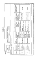
- FIG. 137 is a table illustrating an example of a structure of product information and server registration information according to Embodiment B4.
- FIG. 138 is a table illustrating an example of a structure of product information stored in a product information management unit N 45 according to Embodiment B4.
- FIG. 139 is a flowchart illustrating an example of processing performed by a RF-ID unit N 10 to perform product registration according to Embodiment B4.
- FIG. 140 is a flowchart illustrating an example of processing performed by a mobile device N 20 to perform product registration according to Embodiment B4.
- FIG. 141 is a flowchart illustrating an example of processing performed by a registration server N 40 to perform product registration according to Embodiment B4.
- FIG. 142 is a sequence diagram illustrating an example of controlling power for an air conditioner N 10 J and a TV N 10 A according to Embodiment B4.
- FIG. 143 is a table illustrating an example of a structure of positional information and product control information according to Embodiment B4.
- FIG. 144 is a diagram illustrating a product map generated by a position information generation unit N 48 according to Embodiment B4.
- FIG. 145 is a table illustrating an example of a structure of product information stored in the product information management unit N 45 according to Embodiment B4.
- FIG. 146 is a diagram illustrating a product map generated by the position information generation unit N 48 according to Embodiment B4.
- FIG. 147 is a table illustrating examples of an accuracy identifier according to Embodiment B4.
- FIG. 148 is a diagram illustrating an example of a system according to Embodiment B4.
- FIG. 149 is a diagram illustrating an example of an entire system according to Embodiment B5.
- FIG. 150 is a diagram illustrating an example of an arrangement of products embedded with RF-ID units O 50 according to Embodiment B5.
- FIG. 151 is a diagram illustrating an example of a three-dimensional (3D) map of a building, which is building coordinate information extracted from a building coordinate database O 104 according to Embodiment B5.
- FIG. 152 is a diagram illustrating an example of image data of a 3D map of products which is generated by a program execution unit O 65 according to Embodiment B5.
- FIG. 153 is a diagram illustrating an example of a 3D product map in which image data of FIG. 151 is combined with the already-displayed image data of FIG. 152 by a display unit O 68 d according to Embodiment B5.
- FIG. 154 is a table illustrating examples of an accuracy identifier according to Embodiment B5.
- FIG. 155 is a flowchart illustrating an example of processing for the 3D map according to Embodiment B5.
- FIG. 156 is a flowchart illustrating an example of processing for the 3D map according to Embodiment B5.
- FIG. 157 is a diagram illustrating an example of a specific small power wireless communication system using the 3D map according to Embodiment B5.
- FIG. 158 is a diagram of a network environment for a wireless connection request according to Embodiment B6.
- FIG. 159 is a hardware diagram of a communication device for the wireless connection request according to Embodiment B6.
- FIG. 160 is a functional block diagram of the communication device for the wireless connection request according to Embodiment B6.
- FIG. 161 is a sequence diagram of the wireless connection request according to Embodiment B6.
- FIG. 162 is a flowchart of the wireless connection request according to Embodiment B6.
- FIG. 163 is a diagram of a network environment for a channel setting request according to Embodiment B7.
- FIG. 164 is a functional block diagram of a communication device for the channel setting request according to Embodiment B7.
- FIG. 165 is a diagram illustrating a home.
- FIG. 166 is a diagram illustrating a system.
- FIG. 167 is a diagram illustrating a system.
- FIG. 168 is a diagram illustrating a mobile communication device.
- FIG. 169 is a flowchart of the mobile communication device.
- FIG. 170 is a diagram illustrating a server and the like.
- FIG. 171 is a diagram illustrating appliance information, type information, function information, and the like.
- FIG. 172 is a diagram illustrating a wireless LAN access point and the like.
- FIG. 173 is a flowchart of processing of wireless communication.
- FIG. 174 is a diagram illustrating position information and the like.
- FIG. 175 is a diagram illustrating a mobile communication device.
- FIG. 176 is a diagram illustrating a remote controller and the like.
- FIG. 177 is a diagram illustrating a mobile communication device.
- Embodiments A (A1 to A13) and B (B1 to B7) The following describes Embodiments A (A1 to A13) and B (B1 to B7).
- Embodiment B (B1 to B7) is directly (comparatively closely) related to the claims at the time of filing (the matter of comparative significance at the time of filing).
- Embodiment B4 is most closely related to the claims at the time of filing.
- Embodiment B4 may be understood first.
- Embodiment B (B1 to B7) may be understood prior to Embodiment A (A1 to A13).
- FIGS. 131 to 148 and FIGS. 165 to 177 .
- FIGS. 131 to 148 and FIGS. 165 to 177 .
- FIGS. 131 to 148 and FIGS. 165 to 177 ) may be understood first.
- FIGS. 114 to 177 Drawings closely related to Embodiment B (B1 to B7) are, for example, FIGS. 114 to 177 . Hence, FIGS. 114 to 177 may be understood prior to FIGS. 1 to 113 .
- FIGS. 114 to 177 relating to Embodiment B noted above, it is also preferable to understand, for example, FIGS. 165 to 177 prior to other drawings.
- FIGS. 165 to 177 for understanding of the above-mentioned matter of significance at the time of filing.
- the following mobile communication device is disclosed.
- the mobile communication device may include: an appliance information obtainment unit (an appliance information obtainment unit 98 n ) that obtains, from an appliance (e.g. an appliance 98 a in FIG. 167 (such as a TV N 10 A in FIG. 165 )) installed at a predetermined position (e.g. the home 99 (inside the home 99 ) in FIG. 165 ), appliance information (appliance information 98 n 1 ) by proximity wireless communication (proximity wireless communication 98 c 1 , communication according to NFC) between the installed appliance and the mobile communication device (e.g. a mobile communication device 98 b ), the appliance information specifying the appliance (the first appliance 98 a ) from among a plurality of appliances (e.g.
- an appliance information obtainment unit an appliance information obtainment unit 98 n
- an appliance information obtainment unit 98 n that obtains, from an appliance (e.g. an appliance 98 a in FIG. 167 (such as a TV N 10 A in FIG. 165
- a position information obtainment unit (a position information obtainment unit 98 j ) that obtains position information (position information 98 j 1 ) indicating a position (a position of the appliance 98 a , a position of the TV N 10 A) of the mobile communication device when the proximity wireless communication is performed between the installed appliance and the mobile communication device (as a result of, for example, a movement 98 b 1 of the mobile communication device 98 b to touch the appliance 98 a ) (i.e.
- the proximity wireless communication is performed where the position of the installed appliance (the appliance 98 a (the TV N 10 A)) is the same position as the position of the mobile communication device); and a transmission unit (a transmission unit 98 o ) that transmits transmission information (transmission information 98 o 1 ) to a predetermined server (a server 98 c , e.g. a server of a manufacturer of the appliance 98 a situated outside the home 99 and connected to a communication line 99 b in FIG.
- a predetermined server a server 98 c , e.g. a server of a manufacturer of the appliance 98 a situated outside the home 99 and connected to a communication line 99 b in FIG.
- the transmission information including the appliance information (the appliance information 98 n 1 ) obtained by the proximity wireless communication and the obtained position information (the position information 98 j 1 ) (at the same position (the position of the TV N 10 A)).
- the mobile communication device may further include a detection unit (a communication detection unit 98 q in FIG. 177 ) that detects that the proximity wireless communication (the proximity wireless communication 98 c 1 ) is performed between the installed appliance and the mobile communication device (upon a touching operation or the like), the proximity wireless communication being performed in the case where the appliance (the appliance 98 a ) is installed at the predetermined position (the home 99 ), wherein the transmission unit transmits the transmission information (the transmission information 98 o 1 ) to the predetermined server in the case where the detection unit detects that the proximity wireless communication is performed, the transmission information being required to be transmitted to (e.g.
- a detection unit a communication detection unit 98 q in FIG. 177
- the transmitted transmission information includes the appliance information (the appliance information 98 n 1 ) specifying the installed appliance from among the plurality of appliances, the appliance information obtainment unit obtains the appliance information from the appliance by the proximity wireless communication, the transmitted transmission information includes position information (the position information 98 j 1 ) indicating the position at which the appliance is installed, and the position information obtainment unit obtains, as the position information indicating the position of the appliance, the position information (the position information 98 j 1 ) indicating the position of the mobile communication device (the mobile communication device 98 b ) when the proximity wireless communication is performed between the installed appliance and the mobile communication device.
- the transmission information 98 o 1 including the appliance information 98 n 1 and the position information 98 j 1 which needs to be transmitted to the server 98 c (e.g. the server of the manufacturer of the appliance 98 a ) in the case where the appliance 98 a is installed in the home 99 , can be transmitted by a simple operation such as a touching operation to initiate the proximity wireless communication 98 c 1 .
- the device that performs the proximity wireless communication 98 c 1 is the mobile communication device 98 b such as a mobile phone, with there being no need to add a new structure to perform the proximity wireless communication 98 c 1 . This contributes to a lower cost.
- the device is the mobile communication device 98 b , with there being no need to add a new structure to obtain the position information. This contributes to a sufficiently lower cost. That is, an extent of cost reduction can be increased.
- the appliance (the appliance 98 a ) is a home appliance (e.g. the TV N 10 A or a FF heater N 10 K in FIG. 165 ) in the home (the home 99 ), and the mobile communication device is a mobile phone of a resident of the home in which the appliance is installed, a smartphone of the resident with a mobile phone function, or the like.
- a home appliance e.g. the TV N 10 A or a FF heater N 10 K in FIG. 165
- the mobile communication device is a mobile phone of a resident of the home in which the appliance is installed, a smartphone of the resident with a mobile phone function, or the like.
- the obtained position information may specify a movement (a movement 96 e in FIG. 172 ) of the mobile communication device from a base point (a base point 98 bx in FIG. 172 , the access point 99 c in FIG. 165 ) to the position at which the appliance (e.g. a first appliance 96 c , a second appliance 96 d (the FF heater N 10 K, the TV N 10 A in FIG. 165 )) is installed, to indicate a first position (a first position 96 c P in FIG. 172 , the position of the FF heater N 10 K in FIG.
- the server (the server 98 c in FIG. 172 (e.g. a server (home server) 99 a in FIG. 165 )) to which the transmission information is transmitted performs control so that wireless communication in a first mode (low-power wireless communication 96 f 1 ) is performed between a predetermined wireless communication device (a processor 96 a , the access point 99 c in FIG.
- the installation appliance 165 and the installed appliance in the case where the movement (the movement 96 e ) specified by the position information in the transmission information is the first movement, and wireless communication in a second mode (high-power wireless communication 96 f 2 ) is performed between the predetermined wireless communication device and the installed appliance in the case where the specified movement is the second movement.
- wireless communication in a suitable mode (the wireless communication 96 f 1 , 96 f 2 ) corresponding to the position (the first position 96 c P, the second position 96 d P) at which the appliance 98 a is installed in the home 99 may be performed by transmitting the transmission information 98 o 1 as described above.
- the position information obtainment unit may include an acceleration sensor (an acceleration sensor 98 j 2 x in FIG. 175 ) that detects an acceleration when the mobile communication device moves (the movement 96 e in FIG. 172 ) to the position at which the appliance is installed (from the base point (the base point 98 bx in FIG. 172 , the access point 99 c in FIG. 165 )), wherein the obtained position information (the position information 98 j 1 ) specifies the movement (the movement 96 e ) according to the detected acceleration, to indicate the position (the position of the appliance 98 a (e.g. the first appliance 96 c in FIG. 172 )) of the mobile communication device after the specified movement (the movement 96 e ), as the position at which the appliance is installed.
- an acceleration sensor an acceleration sensor 98 j 2 x in FIG. 175
- the obtained position information specifies the movement (the movement 96 e ) according to the detected acceleration, to indicate the position (the position of the appliance 98
- the predetermined position at which the appliance is installed is inside a home, wherein the proximity wireless communication (the proximity wireless communication 98 c 1 in FIG. 167 ) is communication according to Near Field Communication (NFC) performed when, in the case where the appliance is installed in the home, a user of the mobile communication device in the home in which the appliance is installed performs an operation ( 98 b 1 in FIG. 167 ) of touching the mobile communication device to the installed appliance.
- NFC Near Field Communication
- the mobile communication device may also be implemented, for example, as described in “Other Variations” or in Embodiments A and B.
- the description of “Other Variations” appears at the end of this section, i.e., “Description of Embodiments”, and should be referenced when necessary.
- Embodiments A (A1 to A13) and B (B1 to B7) described below is a relatively new field with various possibilities, where it is relatively difficult to predict what kinds of technologies will be widely available in the future.
- Embodiments A1 to A13, B1 to B7 describe a relatively wide variety of technologies (e.g. Embodiments A1 to A13, B1 to B7).
- Embodiment A See, for example, FIGS. 1 to 113 for understanding of Embodiment A.
- Embodiment B See, for example, FIGS. 114 to 177 ( FIGS. 114 to 164 and 165 to 177 ) for understanding of Embodiment B.
- FIGS. 40A , 40 B, and 40 C e.g. each of FIGS. 40A , 40 B, and 40 C
- FIGS. 42A to 42D the whole drawing including FIGS. 40A , 40 B, and 40 C (e.g. each of FIGS. 40A , 40 B, and 40 C) is referred to as “FIG. 40 ” when necessary.
- FIGS. 42A to 42D the same applies to FIGS. 42A to 42D and the like.
- each apparatus (Embodiments A (A1 to A13) and B (B1 to B7), other variations) may be implemented as follows.
- the components of the apparatus may typically be realized by Large Scale Integration (LSI) as an integrated circuit.
- the components may each be implemented individually as one chip, or may be partly or wholly implemented on one chip.
- the integrated circuit may be referred to as any of IC, system LSI, super LSI, ultra LSI, or the like, depending on the degree of integration.
- the integrated circuit according to the embodiments may be referred to as any of these terms.
- the integrated circuit method is not limited to LSI, and may be realized by a dedicated circuit or a general-purpose processor.
- a Field Programmable Gate Array (FPGA) or a reconfigurable processor capable of reconfiguring connections and settings of circuit cells in an LSI circuit may also be used.
- a communication device may be a subordinate conception of the following communication device X (e.g. FIGS. 132 , 135 , 115 , 116 , 127 ).
- the communication device X is a communication device (e.g. a mobile device N 20 in FIGS. 135 and 132 , a communication device Y 02 in FIG. 127 , a communication device M 1101 in FIGS. 115 and 116 , a communication device M 1101 S or M 1101 R in FIG. 120 ) that reads terminal device information from a terminal device (e.g. the TV N 10 A in FIGS. 134 and 135 , a terminal device Y 01 in FIG. 127 ) by proximity wireless communication (RF tag communication), and transmits the read terminal device information to a server apparatus (a registration server N 40 in FIGS. 135 and 133 , a server Y 04 in FIG.
- a server apparatus a registration server N 40 in FIGS. 135 and 133 , a server Y 04 in FIG.
- the communication device X includes: a terminal device information obtainment unit (a RF-ID reader/writer N 21 in FIGS. 135 and 132 , a device UID obtainment unit M 1202 in FIG. 116 ) that obtains the terminal device information (information in a memory N 13 in FIG. 131 , product information in (a) in FIG. 137 , information in a ROM Y 015 in FIG. 127 ) from the terminal device (e.g. the TV N 10 A in FIG.
- a terminal device information obtainment unit a RF-ID reader/writer N 21 in FIGS. 135 and 132
- a device UID obtainment unit M 1202 in FIG. 116 that obtains the terminal device information (information in a memory N 13 in FIG. 131 , product information in (a) in FIG. 137 , information in a ROM Y 015 in FIG. 127 ) from the terminal device (e.g. the TV N 10 A in FIG.
- the terminal device information including at least terminal device identification information for identifying manufacturing information of the terminal device
- a communication device information storage unit e.g. a memory unit N 25 in FIG. 132 , a ROM Y 025 in FIG. 127
- a communication device information storage unit e.g. a memory unit N 25 in FIG. 132 , a ROM Y 025 in FIG. 127
- stores communication device information including at least communication device identification information (information in the memory unit N 25 in FIG. 132 , a product serial number stored in the ROM Y 025 in FIG. 127 ) for identifying manufacturing information of the communication device
- an information adding unit a CPU N 34 in FIG. 132 , a registration information generation unit M 1204 in FIG. 116 , an information adding unit Y 035 in FIG.
- a communication unit (a communication unit N 30 in FIG. 132 , a registration information transmitting/receiving unit M 1207 in FIG. 116 , a communication unit Y 036 in FIG. 127 ) that transmits the transmission information generated by the information adding unit to the server apparatus via the general-purpose network.
- the communication unit specifies, as the server to which the transmission information is to be transmitted, the server (e.g.
- the registration server N 40 in FIG. 135 indicated by the terminal device information based on the terminal device information (e.g. “address, of registration server” in the product information in (a) in FIG. 137 ) obtained from the terminal device (the TV N 10 A in FIG. 134 ), and communicates with the specified server.
- the terminal device information e.g. “address, of registration server” in the product information in (a) in FIG. 137
- the communication device X may further include a position information obtainment unit (a GPS N 31 or a 6-axis sensor N 32 in FIG. 132 , a position information obtainment unit M 1206 in FIG. 116 , a position information determination unit Y 027 in FIG. 127 ) that obtains position information of the communication device.
- the position information obtainment unit may obtain the position information of the communication device at a timing when the proximity wireless communication between the terminal device (e.g. the TV N 10 A in FIG. 134 ) and the communication device is established in the terminal device information obtainment unit, wherein the communication device information includes the position information of the communication device obtained by the position information obtainment unit.
- the communication device information may include identification information (home ID) of a home (the home in FIG. 134 ) or a person (the user of the communication device).
- the communication device X may have the following structure.
- the communication device X is a mobile terminal that is included in a HEMS (a system in FIGS. 134 and 135 ) and carried by the user, thus having the same position as the user.
- a HEMS a system in FIGS. 134 and 135
- the terminal device information obtainment unit performs the proximity wireless communication with the terminal device only in the case of the proximate distance.
- the communication unit causes the server apparatus to perform processing (e.g. control of the terminal device) for the terminal device (the TV N 10 A in FIG. 134 ) with which the proximity wireless communication is performed, from among a plurality of terminal devices (e.g. a plurality of terminal devices in FIG. 134 , or a plurality of terminal devices including a terminal device in a home other than the home in FIG. 134 ).
- processing e.g. control of the terminal device
- the terminal device the TV N 10 A in FIG. 134
- the communication unit causes the server apparatus to perform processing (e.g. control of the terminal device) for the terminal device (the TV N 10 A in FIG. 134 ) with which the proximity wireless communication is performed, from among a plurality of terminal devices (e.g. a plurality of terminal devices in FIG. 134 , or a plurality of terminal devices including a terminal device in a home other than the home in FIG. 134 ).
- control or the like is easily performed only for the terminal device in the proximate distance, and not for the other terminal devices.
- control or the like is performed only for an appropriate terminal device. This ensures that processing is performed only for an appropriate terminal device.
- Such control or the like only for an appropriate terminal device can be achieved simply by moving the communication device into proximity of the terminal device, without requiring a complex operation. Hence, it is possible to easily perform appropriate processing, i.e., processing only for an appropriate terminal device.
- the terminal device information obtainment unit also obtains, from the terminal device (e.g. the TV N 10 A in FIG. 134 ), the terminal device information for specifying the server apparatus from among a plurality of server apparatuses, by the proximity wireless communication.
- the terminal device e.g. the TV N 10 A in FIG. 134
- the communication unit then causes the server apparatus specified by the terminal device information obtained by the terminal device information obtainment unit, to perform the above-mentioned processing such as control.
- the communication device further includes a home ID transmission unit (a home ID management unit M 1205 in FIG. 116 ) that specifies the home (the home in FIG. 134 ) in which the communication device is used from among a plurality of homes, and transmits, to the server apparatus, a home ID for specifying each appliance (appliances in FIG. 134 ) installed in the home (the home in FIG. 134 ) specified by the home ID from among a plurality of appliances (the appliances in the home in FIG. 134 , appliances in another home), to cause the server apparatus to specify that the terminal device (the TV N 10 A) with which the proximity wireless communication is performed is included in the appliances installed in the home.
- a home ID transmission unit (a home ID management unit M 1205 in FIG. 116 ) that specifies the home (the home in FIG. 134 ) in which the communication device is used from among a plurality of homes, and transmits, to the server apparatus, a home ID for specifying each appliance (appliances in FIG. 134 ) installed in
- the home ID may be transmitted to the server apparatus via a predetermined communication unit (e.g. the registration information transmitting/receiving unit M 1207 in FIG. 116 ) that transmits the home ID.
- a predetermined communication unit e.g. the registration information transmitting/receiving unit M 1207 in FIG. 116
- the home ID transmission unit may cause the server apparatus to specify that the terminal device (the TV N 10 A) is included in the appliances installed in the home, to thereby cause the server apparatus to specify a map (a product map in FIG. 144 ) in which the terminal device (the TV N 10 A) is included in products whose positions are indicated to the user, as a product map (the product map in FIG. 144 ).
- the home ID transmission unit may also cause the server apparatus to specify that the terminal device (the TV N 10 A) is included in the appliances (the appliances in FIG. 134 ), to thereby cause the server apparatus to perform, on the terminal device (the TV N 10 A), processing (e.g. processing of powering ON an appliance nearest the user) to be performed for each of the appliances.
- processing e.g. processing of powering ON an appliance nearest the user
- the communication device further includes the position information obtainment unit (mentioned above) that obtains a position of the terminal device (the TV N 10 A) with which the proximity wireless communication is performed, and causes the server apparatus to specify the obtained position as the position of the terminal device, where the position of the terminal device is the same position as the communication device.
- the position information obtainment unit (mentioned above) that obtains a position of the terminal device (the TV N 10 A) with which the proximity wireless communication is performed, and causes the server apparatus to specify the obtained position as the position of the terminal device, where the position of the terminal device is the same position as the communication device.
- the communication device Y 02 in FIG. 127 may be a subordinate conception (a specific example) of the communication device X.
- Embodiment A1 is described below.
- FIG. 1 is a schematic diagram of Embodiment A1.
- a communication system including an image capturing device (camera) 1 (a communication device 9 A 1 ), a TV 45 , and a server (image server) 42 is illustrated.
- the image capturing device 1 capturing images is illustrated on a left-hand side, while the image capturing device 1 reproducing the captured images is illustrated on a right-hand side.
- the image capturing device 1 is an example of the communication device according to the aspect of the present invention.
- the image capturing device 1 is implemented as a digital camera.
- the image capturing device 1 For units used in capturing images (see the left-hand side in FIG. 1 ), the image capturing device 1 includes a first power supply unit 101 , a video processing unit 31 , a first antenna 20 , a first processing unit 35 , a second memory 52 , and a RF-ID second antenna 21 .
- the second memory 52 holds medium identification information 111 , captured image state information 60 , and server specific information 48 .
- the RF-ID antenna 21 is used for a RF-ID unit.
- the image capturing device 1 includes the first power supply unit 101 , a first memory 174 , a power detection unit 172 , an activation unit 170 , the second memory 52 , a second processing unit 95 , a modulation switch unit 175 , a communication unit 171 , a second power supply unit 91 , and the RF-ID antenna 21 .
- the second memory 52 holds medium identification information 111 , captured image state information 60 , and the server specific information 58 .
- the TV 45 is an example of an apparatus (device) connected with a reader via a communication path.
- the TV 45 is a television receiving apparatus used to display image data captured by the image capturing device 1 .
- the TV 45 includes a display unit 110 and a RF-ID reader/writer 46 .
- the server 42 is a computer that holds image data uploaded from the image capturing device 1 to the server 42 and that downloads the image data to the TV 45 .
- the server 42 has a storage device in which data (image data) 50 is stored.
- the images are converted to captured data (image data) by the video processing unit 31 . Then, in communicable conditions, the image data is wirelessly transmitted to an access point using the first antenna 20 for a wireless Local Area Network (LAN) or Worldwide Interoperability for Microwave Access (WiMAX), and eventually recorded as the data 50 via, for example, the Internet to the predetermined server 42 .
- LAN Local Area Network
- WiMAX Worldwide Interoperability for Microwave Access
- the first processing unit 35 records the captured image state information 60 regarding the captured image data onto the second memory 52 in a RF-ID unit 47 in the image capturing device 1 .
- the captured image state information 60 recorded by the first processing unit 35 or the like indicates at least one of (a) date and time of capturing each of the images, (b) the number of the captured images, (c) date and time of finally transmitting (uploading) an image, (d) the number of transmitted (uploaded) images, and (e) date and time of finally capturing an image.
- the captured image state information 60 includes (f) serial numbers of images that have already been uploaded or images that have not yet been uploaded; (g) a serial number of a finally captured image; and the like.
- the first processing unit 35 generates a Uniform Resource Locator (URL) of the data 50 that is uploaded to the server 42 .
- the first processing unit 35 records the server specific information 48 (URL) onto the second memory 52 .
- the server specific information 48 is used to access the image data (the data 50 in FIG. 1 ).
- the medium identification information 111 is also recorded on the second memory 52 .
- the medium identification information 111 is used to determine whether the device embedded with the RF-ID (RF-ID unit 47 ) is a camera, a card, or a post card.
- the second memory 52 When a main power (the first power supply unit 101 such as a battery) of the camera (the image capturing device 1 ) is ON, the second memory 52 receives power from the main power. Even if the main power of the camera is OFF, the external RF-ID reader/writer located outside supplies power to the RF-ID antenna 21 of the RF-ID unit 47 . This enables the passive second power supply unit 91 without any power like a battery to adjust a voltage to provide power to respective units in a RF-ID circuit unit including the second memory 52 . Thereby, it is possible to supply power to the second memory 52 so that the data in the second memory 52 is recorded/reproduced and transmitted/received by the image capturing device 1 .
- the first power supply unit 101 such as a battery
- the second power supply unit 91 is a circuit generating power from radio waves received by the second antenna 21 .
- the second power supply unit 91 includes a rectifier circuit and the like. Whenever the main power is ON or OFF, the data in the second memory 52 is read and written by the second processing unit 95 . When the main power is ON, the data in the second memory 52 can be read and written also by the first processing unit 35 .
- the second memory 52 is implemented as a nonvolatile memory, and both the first processing unit 35 and the second processing unit 95 can read and write data from and to the second memory 52 .
- the image capturing device 1 When the image capturing device 1 completes capturing images of a trip or the like and then the captured images are to be reproduced, the following processing is performed as illustrated on the right side of FIG. 1 as being the situation of reproducing images.
- the image capturing device 1 is moved into proximity of the RF-ID reader/writer 46 of the TV 45 , by the user of the image capturing device 1 or the like. Then, the RF-ID reader/writer 46 supplies power to the RF-ID unit 47 via the antenna 21 . Based on the supplied power, the second power supply unit 91 provides power to the units in the RF-ID unit 47 , even if the main power (the first power supply unit 101 ) of the image capturing device 1 is OFF.
- the captured image state information 60 and the server specific information 58 are read by the second processing unit 95 from the second memory 52 , and transmitted to the TV 45 via the antenna 21 by the second processing unit 95 or the like.
- the TV 45 generates a URL based on the server specific information 58 , then downloads the image data of the data 50 from the server 42 specified by the URL, and eventually displays, on the display unit 110 , thumbnails or the like of images in the image data.
- the determination result is displayed on the display unit 110 . If necessary, the image capturing device 1 is activated to upload, to the server 42 , image data of the captured image not yet uploaded.
- FIG. 2 is an external view of the image capturing device 1 .
- FIG. 2 are an external front view, an external back view, and an external right side view, respectively, of the image capturing device 1 according to the present invention.
- the antenna 20 used for a wireless LAN and the antenna 21 used for the RF-ID unit are embedded in a right side of the image capturing device 1 .
- the antennas are covered with an antenna cover 22 made of a material not shielding radio waves.
- the RF-ID unit operates at a frequency of 13.5 MHz, while the wireless LAN operates at a frequency of 2.5 GHz. The significant difference in frequency prevents interference between them.
- the two antennas 20 and 21 are seen overlapping with each other from the outside, as illustrated in (c) in FIG. 2 .
- the structure decreases an installation area of the antennas, eventually reducing a size of the image capturing device 1 .
- the structure also enables the single antenna cover 22 to cover both of the two antennas as illustrated in (c) in FIG. 2 , so that the part made of the material not shielding radio waves is minimized.
- the material not shielding radio waves such as plastic, has a strength lower than that of a metal. Therefore, the minimization of the material can reduce a decrease in a strength of a body of the image capturing device 1 .
- the image capturing device 1 further includes a lens 6 and a power switch 3 .
- the units assigned with reference signs 2 to 16 will be described later.
- FIG. 3 is a detailed block diagram of the image capturing device 1 .
- Image data captured by an image capturing unit 30 is provided to a recording/reproducing unit 32 via the video processing unit 31 and then recorded onto a third memory 33 .
- the image data is eventually recorded onto an Integrated Circuit (IC) card 34 that is removable from the image capturing device 1 .
- IC Integrated Circuit
- the above processing is instructed by the first processing unit 35 that is, for example, a Central Processing Unit (CPU).
- the image data such as captured photographs or video, is provided to an encryption unit 36 , a transmission unit 38 in a communication unit 37 , and then the first antenna 20 , in order to be transmitted to an access point or the like by radio via a wireless LAN, WiMAX, or the like. From the access point or the like, the image data is transmitted to the server 42 via the Internet 40 . In the above manner, the image data such as photographs is uploaded.
- CPU Central Processing Unit
- the image data in the server 42 is different from the image data captured by the image capturing device 1 .
- the RF-ID reader/writer 46 of the TV 45 or the like reads the server specific information 48 and the like from the second memory 52 in the RF-ID unit 47 of the image capturing device 1 . Then, based on the readout information, a URL or the like of the server 42 is generated. According to the URL, the TV 45 accesses the server 42 to access the data 50 such as a file, folder, or the like uploaded by the image capturing device 1 . Then, the TV 45 downloads the uploaded images from among the images captured by the image capturing device 1 , and displays the downloaded images.
- the server specific information 48 and the like from the second memory 52 in the RF-ID unit 47 of the image capturing device 1 . Then, based on the readout information, a URL or the like of the server 42 is generated. According to the URL, the TV 45 accesses the server 42 to access the data 50 such as a file, folder, or the like uploaded by the image capturing device 1 . Then, the TV 45 downloads the uploaded images from among the images
- the first processing unit 35 causes a recording/reproducing unit 51 to indicate information regarding a state of captured images, such as information of uploading state, to the captured image state information 55 in the second memory 52 .
- FIG. 4 is a block diagram of the second memory 52 .
- synchronization information 56 ( FIG. 4 ) is recorded.
- the synchronization information 56 indicates whether or not image data in the server 42 matches image data captured by the camera, in other words, whether or not the image data in the server 42 is in synchronization with the image data captured by the camera.
- the TV 45 reads the captured image state information 55 from the second memory 52 via the second antenna 21 .
- the captured image state information 55 makes it possible to instantly determine whether or not the data 50 in the server lacks any image.
- the determination result is displayed on the display unit of the TV 45 .
- the TV 45 also displays a message of “Please upload images” to a viewer.
- the TV 45 issues an instruction to the camera via the RF-ID antenna 21 to transmit an activation signal to the activation unit 170 , thereby supplying power to the first power supply unit 101 of the image capturing device 1 .
- the TV 45 causes the image capturing device 1 to upload, to the server 42 , the images in the first memory 174 or the like of the image capturing device 1 , which have not yet been uploaded, via a wireless LAN, a wired LAN, the RF-ID antenna 21 , or the like.
- the thumbnails can shorten apparent upload time and display time, suppressing unpleasant feeling of the user.
- RF-ID of a HF band has a transfer amount of several hundreds kbps.
- development of RF-ID having a quad-speed has been examined.
- the quad-speed RF-ID has a possibility of achieving a transfer amount of several Mbps. If thumbnails of images not yet uploaded are transmitted, it is possible to transmit several dozens of thumbnails in one second. If thumbnails are displayed in a list, thumbnails of all images including images not yet uploaded can be displayed on the TV within a time period a general user can tolerate. The above is one of practical solutions.
- the most speedy and stable path is selected from a wireless LAN, the RF-ID antenna 21 , and a wired LAN, to be used for uploading and displaying on the TV.
- the communication unit 171 transmitting signals to the second antenna 21 performs communication with the outside by a low-speed modulation method.
- the communication unit 171 switches the modulation method to a modulation method having a large signal point, such as Quadrature Phase Shift Keying (QPSK), 16-Quadrature Amplitude Modulation (QAN), or 64-QAN, as needed, in order to achieve high-speed transfer to upload the image data not yet uploaded in a short time.
- QPSK Quadrature Phase Shift Keying
- QAN 16-Quadrature Amplitude Modulation
- 64-QAN 64-QAN
- the power detection unit 172 detects, for example, that the first power supply unit 101 or the like does not have enough power or that the image capturing device 1 is not connected to an external power
- the first power supply unit 101 stops supplying power and the modulation switch unit 175 switches the modulation method employed by the communication unit 171 to a modulation method having a smaller signal point or less transfer rate.
- the capacity of the first power supply unit 101 is reduced to be equal to or less than a set value.
- the second processing unit 95 , the communication unit 171 , or the like sends a power increase request signal to the RF-ID reader/writer 46 of the TV 45 via the second antenna 21 , to request for power support.
- the RF-ID reader/writer 46 increases providing power to have a value greater than the set value for the power used in reading data from the RF-ID unit. Since the RF-ID unit receives more power via the antenna 21 , the RF-ID unit can provide power to the communication unit 171 or the first processing unit 35 . Thereby, a power amount of a battery 100 for the first power supply unit 101 is not reduced. Or, without the battery 100 , the image capturing device 1 can practically and unlimitedly continue transmission.
- uploaded-image-data information 60 in FIG. 3 can be used.
- uploaded-image-data information 60 uploaded-image information 61 such as serial numbers of photographs, is recorded.
- hashed information 62 generated by hashing the information 61 . As a result, a data amount is reduced.
- the TV 45 can read the above information to be compared to information of images captured by the camera, thereby obtaining information of images not yet uploaded.
- not-yet-uploaded image data existence identification information 63 can be used.
- the not-yet-uploaded image data existence identification information 63 includes an existence identifier 64 indicating whether or not there is any image not yet uploaded. Since existence of images not yet uploaded is notified, data in the second memory 52 can be significantly reduced.
- not-yet-uploaded-image number 65 indicating the number of images not yet uploaded. Since the image capturing device 1 allows the TV 45 to read the information, a viewer can be informed of the number of images to be uploaded. In this case, a data capacity in addition to the number is recorded as the captured image state information 55 . Thereby, the image capturing device 1 enables the TV 45 to display a more exact prediction time required to upload images not yet uploaded.
- not-yet-uploaded image information hashed information 67 that is generated by hashing information regarding images not yet uploaded.
- captured image information 70 e.g. serial numbers of all captured images.
- the TV 45 later accesses the server 42 to match the serial numbers to images uploaded to the server 42 .
- use of hashed information 71 generated by hashing the captured image information 70 can compress the captured image information 70 .
- the second memory 52 further stores Unique IDentification (UID) 75 of the RF-ID unit, camera ID 76 , and the medium identification information 111 . Even if the main power of the camera (except a sub-power for backup etc. of a clock) is OFF, these pieces of information can be read by the TV 45 via the second antenna 21 to be used for identifying the camera or the user or authenticating a device (apparatus). When the user comes back from an overseas trip or the like, the camera is likely to have a small charge amount of the battery. However, according to Embodiment A1 of the present invention, the camera can be operated to transmit information without battery, which is highly convenient for the user.
- UID Unique IDentification
- the medium identification information 111 includes an identifier or the like indicating whether the medium or device embedded with the RF-ID unit is a camera, a camcorder, a post card, a card, or a mobile phone.
- the identifier enables the TV 45 to identify the medium or device. Thereby, the TV 45 can display a mark or icon of the camera or postcard on a screen as illustrated in FIG. 22 , as will be described.
- the TV 45 can also change processing depending on the identifier.
- FIG. 5 is a block diagram of the second memory in the image capturing device according to Embodiment A1.
- the second memory 52 also stores image display method instruction information 77 .
- image display method instruction information 77 For example, in the situation where a list display 78 (information of whether or not to perform list display) in FIG. 5 is selected, when the second antenna 21 is moved into proximity of the RF-ID reader/writer 46 of the TV 45 , the image capturing device 1 (camera) causes the TV 45 to display a list of thumbnails of images, such as photographs.
- the image capturing device 1 causes the TV 45 to sequentially display images from a newer one or an older one.
- the server specific information 48 allows a camera operator to display images on the TV screen by a preferred method.
- the server specific information 48 includes server URL generation information 80 that is source information from which a server URL is generated.
- the server URL generation information 80 is login ID 83 .
- the server specific information 48 has a region in which server address information 81 and user identification information 82 are recorded. In practical, login ID 83 and the like are recorded. In addition, there is a region for storing a password 84 . An encrypted password 85 may be stored in the region.
- the above pieces of information are used to generate an URL by a URL generation unit 90 that is provided in the image capturing device 1 , the RF-ID unit 47 , the camera function used for capturing images in the image capturing device 1 , or the TV 45 .
- the URL is used for accessing a group of images corresponding to the image capturing device 1 or the user in the server 42 . If the URL generation unit 90 ( FIG. 5 ) is provided in the RF-ID unit 47 , the URL generation unit 90 receives power from the second power supply unit 91 .
- the above structure allows the TV 45 reading the RF-ID unit 47 in the camera to instantly obtain the pieces of information regarding uploading state, the sever address information, the login ID, the password, and the like. Thereby, the TV 45 can download image data corresponding to the camera from the server 42 , and display the image data at a high speed.
- the RF-ID reader/writer supplies power to the second power supply unit 91 to activate (operate) the image capturing device 1 . Therefore, power of the battery 100 in the image capturing device 1 is not reduced.
- the first power supply unit 101 receives power from the battery 100 to provide power to the units in the camera.
- a third power supply unit 102 provides weak power to the clock 103 and the like.
- the third power supply unit 102 supplies backup power to a part of the second memory 52 .
- the RF-ID unit 47 receives power from the second antenna to provide power to the second power supply unit 91 , thereby operating the second processing unit 95 , or operating a data receiving unit 105 , a recording unit 106 , a reproducing unit 107 , a data transfer unit 108 (the communication unit 171 ), and the second memory 52 .
- FIG. 7 is a flowchart of processing performed by the camera or card and processing performed by the TV and the RF-ID reader/writer.
- the processing performed by the image capturing device 1 (referred to also as a “medium” such as a camera or card) and the processing performed by the TV and the RF-ID reader/writer are explained with reference to a flowchart of FIG. 7 .
- Step 150 b If the main power is OFF at Step 150 a in FIG. 7 , it is determined at Step 150 b whether or not activation setting of the RF-ID reader/writer for the main power OFF is made. If the activation setting is made, then the RF-ID reader/writer 46 is turned ON at Step 150 c and changed to be in a power saving mode at Step 150 e.
- Step 150 f impedance or the like of an antenna unit is measured, or a nearby sensor is measured.
- the RF-ID unit is moved into proximity of an antenna of the RF-ID reader/writer 46 at Step 150 g , it is detected at Step 150 g whether or not the RF-ID unit is in proximity of or contacts the antenna. If it is detected that the RF-ID unit is in proximity of or contacts the antenna, then the RF-ID reader/writer 46 starts supplying power to the antenna of the medium at Step 150 h .
- Step 150 k in the medium, the second power supply unit is turned ON and thereby the second processing unit starts operating.
- Step 150 m communication between the medium (camera or card) and the RF-ID reader/writer 46 starts.
- FIG. 8 is a flowchart of processing that follows the processing in FIG. 7 .
- the TV determines whether or not the RF-ID reader/writer 46 receives communication from the medium. If the RF-ID reader/writer 46 receives communication, then mutual authentication starts at Steps 151 a and 151 f in FIG. 8 . If it is determined at Steps 151 b and 151 g that the mutual authentication is successful, information is read out from the second memory at Step 151 d . At Step 151 e , the readout information is transmitted to the RF-ID reader/writer 46 . At Step 151 i , the RF-ID reader/writer 46 receives the information. At Step 151 j , the TV 45 side makes a determination as to whether or not the identification information or the like of the second memory is correct.
- Step 151 m If the identification information or the like is correct, then it is determined at Step 151 m whether or not the TV 45 has identification information indicating automatic power ON. If the TV 45 has identification information, then it is determined at Step 151 r whether or not a main power of the TV is OFF.
- FIG. 9 is a flowchart of the processing performed by the image capturing device and the TV, according to Embodiment A1.
- the TV 45 side makes a determination as to whether or not the second memory 52 has forced display instruction. If the second memory 52 has the forced display instruction, then the TV 45 side changes an input signal of the TV to a screen display signal for displaying the RF-ID at Step 152 d .
- the RF-ID reader/writer 46 reads format identification information.
- the RF-ID reader/writer 46 reads information from the second memory by changing a format of the information to a format according to the format identification information.
- the TV 45 side makes a determination as to whether or not the second memory has a “password request flag”. If the second memory has the “password request flag”, then the RF-ID reader/writer 46 reads an “ID of TV not requesting password entry” from the second memory at Step 152 h .
- the TV 45 side makes a determination as to whether or not ID of the TV 45 matches the “ID of TV not requesting password entry”. If the ID of the TV 45 does not match the “ID of TV not requesting password entry”, then the medium reads out a password from the second memory at Step 152 q .
- the medium decrypts the password that has been encrypted.
- the medium transmits the decrypted password to the TV 45 side.
- the medium transmits the decrypted password to the TV 45 side.
- the RF-ID reader/writer 46 receives the password.
- the TV 45 displays a password entry screen.
- the TV 45 determines whether or not the input password is correct. The determination may be made by the server 42 . If the determination is made that the input password is correct, then the TV 45 performs display based on the information and program read from the second memory in the RF-ID unit at Step 152 p.
- FIG. 10 is a flowchart of the processing performed by the image capturing device and the TV, according to Embodiment A1.
- the TV 45 side determines whether or not the medium identification information 111 in the RF-ID unit in the second memory indicates that the medium is a camera. If the medium identification information 111 indicates a camera, then the TV 45 displays an icon (characters) of a camera (camera icon) on the display unit at Step 153 b . On the other hand, if the medium identification information 111 does not indicate a camera, then it is determined at Step 153 c whether or not the medium identification information 111 indicates a post card. If the medium identification information 111 indicates a post card, then the TV 45 displays an icon of a post card (post-card icon) at Step 153 d .
- the TV 45 further determines at Step 153 e whether or not the medium identification information 111 indicates an IC card. If the medium identification information 111 indicates an IC card, then the TV 45 displays an icon of an IC card at Step 153 f . On the other hand, if the medium identification information 111 does not indicate an IC card, the TV 45 still further determines at Step 153 g whether or not the medium identification information 111 indicates a mobile phone. If the medium identification information 111 indicates a mobile phone, then the TV 45 displays an icon of a mobile phone on a corner of the TV screen.
- FIG. 11 is a flowchart of the processing performed by the image capturing device and the TV, according to Embodiment A1.
- FIG. 12 is a flowchart of the processing performed by the image capturing device and the TV, according to Embodiment A1.
- FIG. 13 is a flowchart of the processing performed by the image capturing device and the TV, according to Embodiment A1.
- the RF-ID reader/writer 46 reads service detail identification information from the server or the second memory.
- the TV 45 side determines whether or not the service detail identification information indicates image display service.
- the TV 45 side determines whether or not the service detail identification information indicates a post card service such as direct mail.
- the TV 45 side determines whether or not the service detail identification information indicates advertising service.
- the RF-ID reader/writer 46 obtains the server specific information 48 from the second memory of the medium.
- the TV 45 side determines whether or not the second memory stores the URL 92 . If the second memory does not store the URL 92 , then the processing proceeds to Steps 154 h and 154 k at which the TV 45 obtains the server address information 81 and the user identification information 82 from the second memory.
- the TV obtains an encrypted password from the second memory.
- the TV decrypts the encrypted password.
- the TV generates URL from the above pieces of information.
- Step 155 d even if the second memory stores the URL 92 , the TV accesses the server having the URL via the communication unit and the Internet.
- Step 155 k the TV starts being connected to the server 42 .
- the medium reads out operation program existence identifier 119 from the second memory.
- Step 155 e the TV determines whether or not the TV has any operation program existence identifier. If the TV has any operation program existence identifier, it is further determined at Step 155 f whether or not there are plurality of operation programs. If there are a plurality of operation programs, then the TV reads operation program selection information 118 from the second memory at Step 155 r .
- the TV determines whether or not the operation program selection information 118 is set. If the operation program selection information 118 is set, the TV selects directory information of a specific operation program at Step 155 h .
- the medium reads out directory information 117 of the specific operation program on the server from the second memory and provides the directory information 117 to the TV.
- the TV accesses the specific operation program in the directory on the server.
- the server provides the specific operation program to the TV or executes the specific operation program on the server at Step 155 n .
- the TV (or the server) starts execution of the specific operation program.
- the TV determines whether or not the specific operation program is service using images. If the specific operation program is service using images, then the TV starts checking images not yet uploaded at Step 156 b.
- FIG. 6 is a block diagram of image display method instruction information of the image capturing device according to Embodiment A1.
- FIG. 14 is a flowchart of the processing performed by the image capturing device and the TV, according to Embodiment A1.
- the TV reads the not-yet-uploaded image data existence identification information 64 from the medium.
- the TV determines whether or not the not-yet-uploaded image data existence identification information 64 indicates that there is any image not yet uploaded. If there is any image not yet uploaded, the TV reads the not-yet-uploaded-image number 66 and the data capacity 65 from the medium at Step 156 d .
- the TV displays (a) the not-yet-uploaded-image number 66 and (b) a prediction time required to upload images which is calculated from the data capacity 65 regarding image not yet uploaded.
- the TV determines whether or not the medium (camera) is in a state where the medium can automatically upload images. If the medium can automatically upload images, then at Step 156 g , the TV activates the medium (camera) to upload images not yet uploaded to the server via the first antenna 20 or the second antenna 21 by wireless communication or wired communication having contacts. When Step 156 g is completed, the processing proceeds to Step 157 a of FIG. 14 .
- the TV determines whether or not there is a billing program. If there is no billing program, then at Step 157 n , the TV reads identifier 121 regarding the image display method instruction information which is shown in FIG. 6 .
- the TV determines whether or not the server has the image display method instruction information. If the server has image display method instruction information, then at Step 157 p , the TV reads, from the medium, directory information 120 regarding a directory in which image display method instruction information is stored on the server. At Step 157 c , the TV reads, from the medium, the directory information 120 in which the image display method instruction information corresponding to UID or the like is stored. At step 157 d , the TV obtains the image display method instruction information from the server. Then, the processing proceeds to Step 157 f.
- Step 157 e the TV obtains the image display method instruction information from the medium (such as a camera). Then, the processing proceeds to Step 157 f.
- FIG. 15 is a flowchart of the processing performed by the image capturing device and the TV, according to Embodiment A1.
- the TV starts display of images based on the image display method instruction information.
- the TV reads an all-image display identifier 123 from the medium.
- the TV determines whether or not the all-image display identifier 123 indicates that all images are to be displayed. If all images are to be displayed, the TV displays all images at Step 157 r . On the other hand, if all images are not to be displayed, then at Step 157 h , the TV displays a part of images in a specific directory identified by the directory information 124 that is read at Step 157 s from the medium.
- the TV determines whether or not a list display identifier 125 indicates that images are to be displayed in a list. If the images are to be displayed in a list, then the TV reads a display order identifier 122 at Step 157 t . At Step 157 j , the TV displays the images in a list in a date order or an upload order based on the display order identifier. At Step 157 v , the TV reads a slide show identifier 126 from the medium. At Step 157 k , the TV determines whether or not the slide show identifier 126 indicates that images are to be displayed as slide show.
- the TV displays the images as slide show based on the display order identifier 122 . Then, the TV reads image quality prioritization 127 from the second memory of the medium. At Step 158 a of FIG. 15 , the TV determines whether or not the image quality prioritization 127 indicates that the images are to be displayed by prioritizing image quality. If the images are not to be displayed by prioritizing image quality, the TV reads speed prioritization 128 from the medium at Step 158 q and further determines at Step 158 b whether or not the speed prioritization 128 indicates that the images are to be displayed by prioritizing a speed.
- the TV determines at Step 158 c whether or not the server stores display audio.
- the TV reads and checks display audio server directory 130 from the medium.
- the TV accesses the directory in the server to obtain the display audio and outputs the audio.
- the TV determines whether or not all images are to be displayed as priorities. If all images are not to be displayed as priorities, then at Step 158 f , the TV selects a part of the images.
- the TV reads specific directory information 124 from the medium at Step 158 v , and receives images in the specific directory from the server at Step 158 w .
- the TV displays the images in the specific directory. On the other hand, if it is determined at Step 158 e that all images are to be displayed as priorities, then the TV may display all images at Step 158 i .
- the TV determines whether or not the image display is completed. If the image display is completed, then the TV displays a message “view other image(s)?” at Step 158 k . If the user agrees, then the TV displays a menu of images in different directories at Step 158 m.
- FIG. 16 is a flowchart of the processing performed by the image capturing device and the TV, according to Embodiment A1.
- the TV determines whether or not images captured by a specific user are requested. If images captured by a specific user are requested, then at Step 159 b , the TV requests the medium to provide (a) specific user all image information 132 at Step 159 m and (b) a specific user password 133 that is a password of the specific user.
- the TV determines whether or not the password is correct. If the password is correct, then at Step 159 p , the TV reads directory information 134 of a directory of a file storing an image list from the medium.
- the TV accesses the server to access a directory having an image list of the specific user.
- the TV downloads image data in the directory from the server.
- the TV displays the images captured by the specific user.
- the TV starts color correction routine.
- the TV reads camera model information from the camera ID 76 .
- the TV downloads characteristic information of the camera model from the server.
- the TV downloads characteristic information of the TV from the server.
- the server calculates the characteristic information to generate modified information.
- the TV modifies color and brightness of the display unit based on the pieces of characteristic information of the medium (camera) and the TV.
- the TV displays the images with the modified color and brightness.
- FIG. 17 is a flowchart of the processing performed by the image capturing device and the TV, according to Embodiment A1.
- the TV determines whether or not forced print instruction is selected.
- forced print instruction it is determined at Step 160 b whether or not the terminal (the TV in the above example) to which the medium (camera) is moved closer is a printer or a terminal connected to the printer. If the terminal is a printer or a terminal connected to the printer, then the terminal obtains, at Step 160 c , camera model information of the medium (camera) and a model name of the printer for each image data.
- the terminal modifies each piece of information of the server to generate modified information.
- the terminal receives directory information 137 of a directory in which the image data to be printed is stored.
- the terminal accesses the server by using an address of the directory having the image data to be printed (or file name).
- the server sends the image data stored in the directory to the terminal.
- the TV receives the image data to be printed.
- the terminal prints the image data.
- the printing is completed.
- the terminal records, onto the server, an identifier indicating that one printing process is completed.
- the server assigns a print completion identifier to the image data that is stored in the server and has been printed.
- the medium such as a camera or a post card does not have a memory for storing data.
- FIG. 18 is a flowchart of the processing performed by the image capturing device and the TV, according to Embodiment A1.
- FIG. 19 is a flowchart of the processing performed by the image capturing device and the TV, according to Embodiment A1.
- Steps of FIG. 18 follow the numbers 3 , 4 , and 5 in circles in FIG. 8 .
- a main power of the TV is turned ON.
- the TV reads UID of the RF-ID unit from the second memory.
- the TV obtains the UID.
- the TV reads the server specific information 48 from the second memory.
- the TV accesses a server directory.
- the TV searches the server directories for a final server providing service corresponding to the UID.
- the TV determines whether or not such a final server exists. If there is such a final server, then at Step 161 g , the TV accesses the final server and reads a user ID, a password, and a service name from a UID list. At Step 161 h , the TV determines whether or not a password is requested. If the password is requested, then the TV determines at Step 161 i whether or not the readout password is correct. At Step 162 a of FIG. 19 , the TV determines whether or not the service is regarding photographs or video.
- the TV reads, from a specific directory in the server associated with the UID, (a) a corresponding program such as a billing program, (b) a list including an address or a file name of image data to be displayed, (c) image display instruction information, (d) forced display instruction, (e) forced print instruction, and (f) camera ID, and (ii) automatically displays the image data or causes the image data to be printed, based on the above pieces of information and procedure.
- FIG. 20 is a flowchart of the processing performed by the image capturing device and the TV, according to Embodiment A1.
- the TV determines whether or not the user desires to print a specific image. If the user desires to print a specific image, then at Step 162 d , the TV adds data of the specific image to the server associated with the UID or to a print directory of the TV. At Step 162 e , the TV determines whether or not the TV is connected to a printer and there is an independent printer. If so, then, at Step 162 f , the RF-ID unit of the medium such as a post card is moved into proximity of a RF-ID reader/writer of the printer. At Step 163 a of FIG.
- the printer (i) reads UID of the RF-ID from the medium, (ii) thereby reads image data to be printed or a location of the image data from the print directory on the server having the modified information, and (iii) prints the image data.
- the printing is completed. Thereby, the above processing is completed.
- Step 163 i is the number 23 (circle 23 ) in FIG. 19 .
- the TV determines whether or not the service is for shopping. If the service is for shopping, then the TV determines at Step 163 e whether or not authentication is successful. If the authentication is successful, then at Step 163 f , the TV reads, from the server, a shopping/billing program associated with the UID, and executes the program. At Step 163 g , the execution of the program is completed. Thereby, the above processing is completed.
- FIG. 21 is a flowchart of the processing performed by the image capturing device and the TV, according to Embodiment A1.
- a second RF-ID unit on which URLs of relay servers are recorded, is attached to or embedded in the medium such as a post card.
- the medium such as a post card.
- UID of the second RF-ID unit and (b) information for identifying a first URL of a certain relay server are printed to be displayed by a two-dimensional bar-code.
- Step 164 b there is a camera capable of being connected to a main server.
- the camera has a first RF-ID unit on which a first URL of the main server is recorded.
- An image capturing unit in the camera optically reads the two-dimensional bar-code, and converts the readout information to information for identifying (a) the UID of a second RF-ID unit in the post card and (b) a second URL of a relay server.
- Step 164 c the converted information is recorded onto a memory in the camera.
- the camera selects a specific set of images from images captured by the camera, and stores the set of images into a specific first directory in the main server.
- the camera uploads information of first directory (first directory information) as well as the first URL of the main server, to a specific second directory in the relay server having the second URL.
- the camera uploads information for associating the UID of the second RF-ID unit with the second directory, to the relay server having the second URL.
- the medium such as a post card is mailed to a specific person.
- Step 164 f the person receiving the post card moves the RF-ID unit of the post card into proximity of a RF-ID reader of a TV or the like. Thereby, the TV reads, from the RF-ID unit, the second URL of the relay server and the UID of the post card.
- the TV accesses the relay server having the second URL. Then, the TV reads, from the relay server, (a) a program in the second directory associated with the UID and/or (b) the first URL and the first directory information of the main server on which specific image data is recorded. The TV downloads the image data from the main server. The TV displays the image data on a screen.
- the image capturing unit in the image capturing device according to Embodiment A1 of the present invention reads information from the two-dimensional bar-code that is generally printed in a product or post card to record server information. Then, the image capturing device records the information read from the two-dimensional bar-code, as digital information, onto the second memory of the RF-ID unit.
- the image capturing device allows a RF-ID reader of a TV to read the information.
- a TV without an optical sensor for two-dimensional bar-codes can indirectly read information of two-dimensional bar-codes and automatically access a server or the like.
- FIG. 22 is a diagram presenting a display method of the image capturing device and the TV, according to Embodiment A1.
- FIG. 22 illustrates the situation where display is presented when the image capturing device 1 is moved into proximity of a RF-ID antenna 138 of the TV 45 .
- the TV 45 displays a camera icon 140 for notifying that the medium is a camera in the manner described previously.
- the TV 45 displays five blank images 142 a , 142 b , 142 c , 142 d , and 142 e as if these images were taken out from the camera icon 140 .
- the TV 45 displays “tangible” information of images by changing “materials to information”.
- the user can perceive the information of images by more natural sense.
- actual images 143 a , 143 b , and 143 c are displayed as tangible data in the same manner as described above.
- FIG. 22 illustrates the situation where RF-ID is embedded in a post card 139 . Since the RF-ID reader/writer 46 of the TV 45 reads attribute information of the post card from the RF-ID. Thereby, the TV 45 displays a post-card icon 141 at a bottom left corner of the display unit of the TV 45 as illustrated in FIG. 22B . The TV 45 also displays images stored in the server or a menu screen as tangible data in the same manner as described with reference to (a) in FIG. 22 .
- an operation program 116 illustrated in FIG. 4 is transmitted to the TV 45 illustrated in FIG. 3 that is an apparatus (device) communicating with the RF-ID unit 47 of the image capturing device 1 .
- the communicating device (TV 45 ) executes the transmitted program.
- FIG. 23 is a block diagram of a configuration in which the apparatus communicating with the RF-ID unit 47 in the image capturing device 1 executes the transmitted program.
- FIG. 23 illustrates a communication system including a part of the image capturing device 1 (the RF-ID 47 and the second antenna 21 ), the TV 45 , and a remote controller 827 of the TV 45 .
- the image capturing device 1 is implemented as a camera which has the RF-ID unit 47 to perform proximity wireless communication with the RF-ID reader/writer 46 .
- the RF-ID reader/writer 46 is connected to the TV 45 by an infrared communication path.
- the camera includes the antenna 21 , a data receiving unit 105 , the second memory 52 , and the data transfer unit 108 .
- the antenna 21 is used for the proximity wireless communication.
- the data receiving unit 105 receives, via the antenna 21 , an input signal provided from the RF-ID reader/writer 46 .
- the second memory 52 is a nonvolatile memory holding at least (a) the UID unit 75 that is identification information for identifying the image capturing device 1 , and (b) the operation program 116 that is to be executed by the TV 45 with reference to the UID unit 75 .
- the data transfer unit 108 transmits the UID unit 75 and the operation program 116 stored in the second memory 52 to the RF-ID reader/writer 46 via the antenna 21 , according to the input signal received by the data receiving unit 105 .
- the UID unit 75 and the operation program 116 transmitted from the data transfer unit 108 are transmitted to the TV 45 via the data transfer unit 108 , the antenna 21 , the RF-ID reader/writer 46 , and then the infrared communication path.
- the RF-ID unit 47 in the image capturing device 1 has the second memory 52 .
- the second memory 52 holds the operation program 116 .
- the operation program 116 can be executed by the TV 45 communicating with the RF-ID unit.
- the operation program 116 is an example of the program executed by the TV 45 with reference to the identification information of the image capturing device 1 .
- the operation program 116 is, for example, an execution program such as JavaTM program, a virtual-machine script program such as JavascriptTM program, or the like.
- the reproducing unit in the RF-ID unit 47 reads necessary information and the operation program 116 from the second memory 52 .
- the necessary information is required to execute the operation program 116 .
- the necessary information includes the UID unique to the image capturing device 1 , the server specific information including the URL of the server, and the like.
- the necessary information and the operation program 116 are transmitted to the RF-ID reader/writer 46 in the remote controller 827 via the data transfer unit 108 and the second antenna 21 .
- the remote controller 827 remotely controls the TV 45 .
- the RF-ID reader/writer 46 of the remote controller 827 receives the necessary information and the operation program from the RF-ID unit 47 of the image capturing device 1 and stores them into a RF-ID storage unit 6001 .
- a remote-controller signal generation unit 6002 in the remote controller 827 converts the necessary information and the operation program, which are transmitted from the RF-ID unit 47 of the image capturing device 1 and stored in the RF-ID storage unit 6001 , to remote-controller signals.
- the remote-controller signals such as infrared signals, are widely used in communication for present remote controllers.
- a remote-controller signal transmission unit 6003 transmits the remote-controller signals including the operation program which are generated by the remote-controller signal generation unit 6002 .
- a remote-controller signal receiving unit 6004 in the TV 45 receives the remote-controller signals from the remote controller 827 .
- a program execution unit 6005 such as a JavaTM virtual machine, retrieves the necessary information and the operation program in the RF-ID unit 47 of the image capturing device 1 , from the remote-controller signals by using a decryption unit 5504 . Thereby, the program execution unit 6005 executes the operation program.
- FIG. 24 is a flowchart of processing for transferring and executing the operation program stored in the RF-ID unit.
- FIG. 24 is a flowchart of execution of the operation program for “downloading data of images from an image server with reference to identification information (UID in this example) of the image capturing device 1 , and displaying the images as a slide show”.
- identification information UID in this example
- FIG. 25 presents an example of description of the operation program for downloading image and executing slide show.
- the RF-ID reader/writer 46 of the remote controller provides power to the RF-ID unit 47 in the image capturing device 1 via RF-ID communication.
- the UID 75 unique to the image capturing device 1 the URL 48 of the image server (image server URL), and the operation program 116 are read from the second memory 52 (S 6001 ).
- the readout UID, image server URL, and operation program are transmitted to the remote controller 827 via the data transfer unit 108 and the second antenna 21 (S 6002 ).
- the operation program includes server connection instruction 6006 , download instruction 6008 , slide show display instruction 6010 , download-completion-time processing set instruction 6007 , and download-completion-time instruction 6009 .
- the remote controller 827 receives the UID, the image server URL, and the operation program from the image capturing device 1 via the RF-ID reader/writer 46 (S 6003 ). A determination is made as to whether or not receiving is completed (S 6004 ). If receiving is completed, then the UID, the image server URL, and the operation program are stored in the RF-ID storage unit 6001 (S 6005 ). Then, the UID, the image server URL, and the operation program are converted to remote-controller signals transmittable by infrared ray (S 6006 ). A determination is made as to whether or not the user performs a predetermined input operation by the remote controller 827 to instruct to transmit the remote-controller signals to the TV 45 (S 6007 ).
- the remote-controller signal transmission unit 6003 transmits the remote-controller signals including the UID, the image server URL and the operation program to the TV 45 (S 6008 ).
- the remote controller 827 serves also as a relay device that transfers the UID, the image server URL, and the operation program from the image capturing device 1 to the TV 45 by using the embedded RF-ID reader/writer 46 .
- the TV 45 receives the remote-controller signals from the remote controller 827 (S 6009 ).
- the decryption unit 5504 in the TV 45 retrieves (decrypts) the UID, the image server URL, and the operation program from the remote-controller signals (S 6010 ).
- the program execution unit 6005 executes the operation program with reference to the UID and the image server URL (S 6011 to S 6015 ). More specifically, by the operation program, connection between the TV 45 and the image server 42 on a communication network is established with reference to the image server URL (S 6012 , and 6006 in FIG. 25 ).
- image data captured by a specific image capturing unit is selected from the image data 50 stored in the storage device of the image server 42 , and the selected image data is downloaded to the TV 45 (S 6013 , and 6008 in FIG. 25 ).
- the UID is used to select image data associated with the image capturing device 1 indicated by the UID, from among pieces of image data stored in the image server 42 .
- a determination is made as to whether or not the image download is completed (S 6014 ). If the image download is completed, the downloaded images are sequentially displayed as a slide show (S 6015 , and 6007 , 6009 , and 6010 in FIG. 25 ).
- the download-completion-time processing set instruction 6007 in FIG. 25 is instruction for setting processing to be performed when image downloading is completed.
- the download-completion-time processing set instruction 6007 instructs the instruction 6009 as the processing to be performed when image downloading is completed.
- the processing 6009 calls the processing 6010 for performing a slide show of the images.
- the operation program and the necessary information for the operation program are transferred from the image capturing device 1 to the TV 45 via the remote controller 827 .
- the RF-ID reader/writer 46 of the remote controller 827 may be provided to the TV 45 .
- the RF-ID reader/writer 46 may be embedded in the TV 45 .
- the communication path connecting the reader (RF-ID reader/writer 46 ) to the apparatus may be a wireless communication path such as infrared communication path, or a wired signal cable.
- the UID is used to select image data associated with the image capturing device 1 from among pieces of image data stored in the image server 42 .
- the UID it is also possible to use the UID to identify the image server storing the image data.
- UID it is assumed that, in a communication system including a plurality of image servers, UID is associated with an image server storing image data captured by an image capturing device identified by the UID.
- the TV 45 executing the operation program can identify, by using the UID, the image server associated with the UID from the plurality of image servers and thereby download the image data from the identified image server.
- the identification information for identifying the image capturing device 1 is not limited to UID.
- the identification information maybe any other information regarding the image capturing device 1 , such as a serial number, a product serial number, a Media Access Control (MAC) address, or information equivalent to the MAC address, for example, an Internet Protocol (IP) address.
- IP Internet Protocol
- the identification information maybe a Service Set Identifier (SSID) or any information equivalent to SSID.
- SSID Service Set Identifier
- the identification information (UID unit 75 ) for identifying the image capturing device 1 has been described to be stored separately from the operation program 116 . However, the identification information may be stored (described) in the operation program 116 .
- the remote-controller signals (in other words, the communication path connecting the reader to the apparatus) are described to employ infrared ray.
- the remote-controller signals are not limited to the above, but may employ a wireless communication method such as Bluetooth.
- the use of wireless communication that is generally speedier than infrared communication can shorten a time required to transfer an operation program and/or the like.
- the operation program is not limited to the program in the format presented in FIG. 25 .
- the operation program may be described in any other programming language.
- the operation program described in JavaTM can be easily executed by various apparatuses (devices), because the program execution circumstances called JavaVMTM have broad versatility.
- the operation program may be described in a compact programming language in a script format represented by JavascriptTM so as to be stored in a small storage capacity.
- the operation program in such a compact programming language can be stored in the RF-ID unit 47 in the second memory 52 even if the RF-ID unit 47 has a small storage capacity.
- the operation program may be in an executable format applied with processing such as compiling, rather than a source code presented in FIG. 25 .
- the program can reduce a processing load on apparatuses having program execution environments like TV.
- FIG. 26 is a block diagram of (a) the TV changing processing of the operation program according to a language code, and (b) a server storing the program.
- FIG. 27 is a flowchart of processing for changing processing of the operation program according to a language code.
- the following describes, in detail, the processing of changing execution of a program depending on information unique to a display device (such as the TV 45 ) having a RF-ID reader, with reference to FIGS. 26 and 27 .
- the TV 45 illustrated in FIG. 26 further includes a language code holding unit 6013 .
- the program execution unit 6005 reads a language code from the language code holding unit 6013 to connect the TV 45 to the server 42 compliant to the language code. Then, the operation program is executed to download a server program from the server 42 , and executes the downloaded server program.
- the language code indicates Japanese language
- the TV 45 is connected to the server 42 having a program storage unit 6011 in which a server program compliant to Japanese language is stored, and then the server program is obtained from the program storage unit 6011 to be executed in the TV 45 .
- the operation program stored in the RF-ID unit 47 of the image capturing device 1 as illustrated in FIG. 23 executes only connection to the server 42 , while other processing such as image display is executed by the server program downloaded from the server 42 .
- the steps in the above processing are described with reference to FIG. 27 .
- the processing by which the TV 45 receives the operation program and the necessary information for the operation program from the RF-ID unit 47 of the image capturing device 1 is the same as the processing described previously with reference to FIG. 24 .
- the server specific information which the TV 45 receives as remote-controller signals includes two different server addresses which are (a) a sever address of a server 42 compliant to English and (a) a server address of a different server 42 compliant to Japanese.
- the operation program which the TV 45 receives as remote-controller signals includes instruction for connecting the TV 45 to a server indicated by the server connection instruction 6006 in FIG. 25 .
- the TV 45 obtains a language code of the TV 45 (S 6016 ).
- the TV 45 determines whether or not the language code indicates Japanese language (S 6017 ). If the language code indicates Japanese language, then the TV 45 selects, from the server specific information, a sever address of a server having a program storage unit 6011 storing an operation program for processing compliant to Japanese (S 6018 ). On the other hand, if the language code does not indicate Japanese language, then the TV 45 selects, from the server specific information, a server address of a server having a program storage unit 6011 storing an operation program for processing compliant to English (S 6019 ). Next, the TV 45 is connected to the server 42 with reference to the selected server address (S 6021 ). The TV 45 downloads a server program from the server 42 (S 6022 , S 6023 ). The TV 45 executes the downloaded server program in the program execution environments (for example, a virtual machine) of the TV 45 (S 6024 ).
- the program execution environments for example, a virtual machine
- the language code has been described in FIGS. 26 and 27 , but the language code may be replaced by other information. Examples are a product serial number, a serial number of the display device (TV 45 ), and the like each of which indicates a country where the display device is on the market or equipped.
- FIG. 28 is a block diagram of a home network 6500 connecting the image capturing device to the TV by a wireless LAN.
- FIG. 28 illustrates a configuration of a home network 6500 in which the image capturing device 1 and the TV 45 are connected to each other via a wireless LAN or Power Line Communication (PLC).
- PLC Power Line Communication
- access points serve as authentication terminals. If such an existing terminal is to authenticate its communication party, the terminal displays all connectable access points on its screen. The user selects one of the displayed access points from the screen. Then, the user presses a Wired Equivalent Privacy (WEP) key to perform encrypted communication.
- WEP Wired Equivalent Privacy
- the above processing bothers general users.
- a wireless LAN is embedded in home appliances such as a TV, there are so many terminals with which the existing terminal can communicate with authentication. If the user lives in an apartment house, the user can communicate even with terminals in neighbors. As a result, it is difficult for the user to select a terminal to be authenticated. For instance, if a neighbor has a TV 6503 that is the same model as the user's TV 45 , the user has difficulty in distinguishing the TV 45 in the user's house from the TV 6503 based on the information displayed on the screen of the existing device.
- Embodiment A1 of the present invention can solve the above problem.
- RF-ID is used to perform authentication.
- an authentication program including a MAC address 58 is recorded, as an operation program, in the second memory 52 in the RF-ID unit 47 of the image capturing device 1 .
- the authentication program includes not only the MAC address but also a cryptography key for authentication (hereinafter, “authentication cryptography key”) and an authentication command.
- the TV 45 When the TV 45 recognizes that the information provided from the RF-ID unit 47 includes the authentication command, the TV 45 performs authentication processing.
- the communication unit 171 in the RF-ID unit 47 cannot communicate with the TV 45 , until the image capturing device 1 is physically located in proximity of the RF-ID reader/writer 46 . Therefore, it is extremely difficult to intercept the communication between the image capturing device 1 and the TV 45 which is performed in a house.
- the image capturing device 1 since the image capturing device 1 is moved into proximity of the TV 45 to exchange data, it is possible to prevent that the image capturing device 1 authenticates a wrong device (apparatus), such as the TV 6503 in a neighbor or a DVD recorder 6504 in the user's house.
- FIG. 29 presents an example of an authentication method without using RF-ID unit.
- a user inputs, to the TV 45 , (a) MAC addresses of terminals to be authenticated, such as the camera (the image capturing device 1 ) and the DVD recorder 6504 , which the user intends to authenticate for communication, and (b) authentication cryptography keys 6511 for the terminals.
- the TV 45 receiving the inputs transmits an appropriate message called a challenge 6513 , to a target terminal having the MAC address.
- the image capturing device 1 receives the challenge 6513
- the image capturing device 1 encrypts the challenge 6513 using the authentication cryptography key 6511 , and returns the encrypted challenge 6513 to the TV 45 that is a terminal from which the challenge 6513 has been provided.
- the TV 45 In receiving the encrypted challenge 6513 , the TV 45 decrypts the encrypted challenge 6513 using the authentication cryptography key 6511 . Thereby, the TV 45 can authenticate the authentication cryptography key 6511 to prevent user's error and intervention of other malicious users. Next, the TV 45 encrypts a cryptography key 6512 a for data (hereinafter, a “data cryptography key 6512 a ”) using the authentication cryptography key 6511 . Then, the TV 45 transmits the encrypted data cryptography key 6512 a to the image capturing device 1 . Thereby, it is possible to perform the encrypted data communication between the TV 45 and the image capturing device 1 .
- the TV 45 performs the above-described processing also with the DVD recorder 6504 and other apparatuses (terminals) 6505 and 6506 in order to share the data cryptography key 6512 a among them. Thereby, the TV 45 can perform encrypted communication with all terminals (devices, apparatuses, or the like) connected in the home network.
- FIG. 30 presents an example of an authentication method using RF-ID unit.
- FIG. 30 illustrates an authentication method using RF-ID.
- the image capturing device 1 (camera) generates an authentication program 6521 a .
- the camera provides the generated authentication program 6521 a from the RF-ID unit 47 in the camera to a RF-ID unit 46 in the TV 45 .
- the authentication program 6521 a includes an authentication command, a MAC address of the camera, and an authentication cryptography key 6511 for the camera.
- the TV 45 receives the authentication program 6521 a with the authentication command, the TV 45 retrieves the MAC address and the authentication cryptography key 6511 from the RF-ID unit 46 .
- the TV 45 encrypts a data cryptography key 6512 a using the retrieved authentication cryptography key 6511 and transmits the encrypted data cryptography key 6512 a to the retrieved MAC address.
- the transmission is performed by a wireless-LAN device (terminal).
- the authentication method using RF-ID the authentication is performed automatically without any user's input. Therefore, there is no problem caused by user's input errors.
- the image capturing device 1 (camera) needs to be moved into proximity of the TV 45 , it is possible to prevent intervention of other malicious users.
- This authentication method using RF-ID can eliminate pre-processing such as the above-described challenge.
- the action of physically moving the image capturing device 1 (camera) into proximity of the TV 45 enables the user to easily recognize which terminals the camera has authenticated.
- the authentication cryptography key 6511 is not included in the authentication program, the authentication may be performed by a technique of general public key authentication.
- the communication device (medium) is not limited to a wireless LAN, but may be any medium, such as PLC or EthernetTM included in the home network.
- the MAC address may be any identification information for uniquely identifying a communication terminal in the home network.
- FIG. 31 presents an example of an authentication method used when it is difficult to move a terminal into proximity of another terminal.
- FIG. 31 illustrates an authentication method using RF-ID when it is difficult to move a terminal into proximity of another terminal.
- the terminals are a refrigerator and a TV which are difficult to move, it is almost impossible to directly exchange an authentication program between the terminals using RF-ID.
- Embodiment A1 of the present invention can be implemented by relaying the authentication program between the terminals using a device (such as a remote controller (mobile remote controller) 6531 x ) that is an accessory of the terminal.
- a RF-ID reader/writer embedded in the remote controller 6531 x reads the authentication program from a RF-ID unit in the refrigerator. Thereby, the authentication program is stored in a memory in the remote controller 6531 x .
- a user moves the remote controller 6531 x that is mobile.
- the remote controller 6531 x transfers the authentication program from the memory of the remote controller 6531 x , to the RF-ID unit of the TV 45 .
- the transfer from the remote controller 6531 x to the TV 45 is not limited to use RF-ID technology.
- Other communication means such as infrared ray or ZigBee, that is previously set in the remote controller 6531 x can be used. Any medium for which security in communication has already been established may be used.
- FIG. 32 is a flowchart of an example of processing performed by a camera.
- FIG. 32 is a flowchart of authentication performed by the camera (image capturing device 1 ) side.
- the camera In an authentication mode, the camera generates an authentication cryptography key and sets a timer (S 6541 ).
- the camera writes a MAC address of the camera, the generated authentication cryptography key, and an authentication command, into a memory in the RF-ID unit (S 6542 ).
- the camera transfers the information stored in the memory of the RF-ID unit of the camera to the RF-ID unit of the TV (S 6543 ).
- the camera determines whether or not a response of the transfer is received from the TV within a predetermined time period counted by the timer (S 6544 ). If the response is received within the predetermined time period, then the camera decrypts, by using the authentication cryptography key, encrypted data cryptography key included in the response (S 6545 ). The camera starts communicating with the other device (apparatus) using the data cryptography key (S 6546 ). The camera determines whether or not data communication with the TV is successful (S 6547 ). If the data communication is successful, then the authentication is completed. On the other hand, if data cannot be correctly decrypted (in other words, data communication is not successful), then a notification of authentication error is displayed and the authentication is terminated (S 548 ). Referring back to Step S 6544 , if there is no response within the predetermined time period, then the camera cancels the authentication mode (S 6549 ) and then displays a notification of time out error (S 6550 ).
- FIG. 33 is a flowchart of an example of processing performed by the TV.
- FIG. 33 is a flowchart of authentication performed by the TV 45 side.
- the TV 45 determines whether or not received information, which is provided from the RF-ID unit of the camera to the RF-ID unit of the TV 45 , includes an authentication command (S 6560 ). If the received information does not include the authentication command, then the TV 45 performs other processing according to the received information (S 6561 ). On the other hand, if the received information includes the authentication command, the TV 45 determines that the information received from the RF-ID unit of the camera is an authentication program, and therefore encrypts a data cryptography key in the TV 45 using an authentication cryptography key in the authentication program (S 6562 ). Then, the TV 45 transmits the encrypted data cryptography key to the terminal (the camera) having the MAC address designated in the authentication program (S 6563 ).
- the image capturing device 1 described with reference to FIG. 3 generates or updates a program executable by the TV 45 . Then, the image capturing device 1 transmits the program to the TV 45 via the data transmission unit 173 . Thereby, the TV 45 executes the program.
- FIG. 34 is a block diagram of the first processing unit 35 and the second memory 52 of the image capturing device 1 according to Embodiment A1.
- the first processing unit 35 includes a second memory reading unit 7003 , a URL generation unit 7004 , a program generation unit 7005 , a program part storage unit 7006 , and a program writing unit 7007 .
- the second memory reading unit 7003 reads information from the second memory 52 via the recording/reproducing unit 51 .
- the URL generation unit 7004 reads the UID 75 , the server specific information 48 , the captured image state information 55 , and the image display method instruction information 77 from the second memory 52 via the second memory reading unit 7003 . From the above pieces of information, the URL generation unit 7004 generates a URL that is an address of the server 42 to which images have been uploaded from the image capturing device 1 .
- the UID 75 is identification information for identifying the image capturing device 1 .
- the UID 75 is unique to each image capturing device 1 .
- the URL generated by the URL generation unit 7004 includes UID.
- the image server 42 to which images are uploaded, has an image file in a directory unique to each UID. Thereby, a URL address can be generated for each image capturing device 1 .
- the server specific information 48 is a server name for identifying the server to which the images are uploaded. Via a Domain Name Server (DNS), an IP address of the server 42 is determined to connect the image capturing device 1 to the server 42 . Therefore, the server specific information 48 is included in the generated URL.
- DNS Domain Name Server
- the image display method instruction information 77 is information for enabling the user to optionally select the list display 78 , the slide show display 79 , or the like.
- the URL generation unit 7004 generates the URL based on the image display method instruction information 77 .
- the image server since the generated URL includes information indicating the list display 78 or the slide show display 79 , the image server (the server 42 ) can determine based on the URL whether the images are to be displayed as the list display or the slide show display.
- the URL generation unit 7004 As described above, based on the UID 75 , the server specific information 48 , the captured image state information 55 , the image display method instruction information 77 , and the like which are stored in the second memory 52 , the URL generation unit 7004 generates a URL of the image server in which images to be watched are stored. Then, the URL generation unit 7004 provides the generated URL to the program generation unit 7005 .
- the program generation unit 7005 generates a program executable by the TV 45 , based on (a) the URI generated by the URL generation unit 7004 , and (b) forced display instruction 7000 , forced print instruction 136 , and format identification information 7001 stored in the second memory 52 . It should be noted that the program generation unit 7005 can generate a new operation program based on the above-described information, which is a method of generating a new operation program. The program generation unit 7005 can also generate such a new operation program by updating an operation program that has been already generated.
- the program generated by the program generation unit 7005 is executable by the TV 45 .
- the program should be compiled into a machine language used in a system controller (not shown) of the TV 45 , so that the system controller can execute the program.
- the program generation unit 7005 has a compiler to convert the generated program to a program in an executable format.
- the above-described compiler is not necessary if the program in a text format (script) (for example, a general JavaTM script) is executed by a browser in the TV 45 .
- a text format for example, a general JavaTM script
- the URL provided to the program generation unit 7005 is used to connect the TV 45 to the image server (server 42 ) in which images are stored.
- the program generation unit 7005 generates or updates a connection program (hereinafter, referred to also as a “server connection program” or “connection program”) for connecting the TV 45 to the image server.
- the forced display instruction 7000 is optional and used in the following situation. For example, there is the situation where, while the user watches on the TV 45 a TV program provided by general broadcast waves, the RF-ID reader/writer 46 of the TV 45 becomes communicable with the image capturing device 1 via the second antenna 21 . In the situation, the forced display instruction 7000 is used to automatically set the TV 45 into a browser watching mode so that image data provided from the image server is displayed on the TV 45 . If this option is selected, the program generation unit 7005 generates a program for forcing the TV 45 to display image data.
- the forced print instruction 136 is optional and used in the following situation. For example, there is the situation where, while the user watches on the TV 45 a TV program provided by general broadcast waves, the RF-ID reader/writer 46 of the TV 45 becomes communicable with the image capturing device 1 via the second antenna 21 . In the situation, the forced print instruction 136 is used to automatically print image data stored in the image server by a printer (not shown) connected to the TV 45 . If this option is selected, the program generation unit 7005 generates a program for forcing the TV 45 to print image data by the printer.
- the format identification information 7001 is information of a format by which image data is to be displayed.
- the program generation unit 7005 When an option of language code optimization selection in the format identification information 7001 is selected, the program generation unit 7005 generates a program for selecting a URL to be connected, based on the language code set in the TV 45 .
- the following is an example in the situation where the option of language code optimization selection in the format identification information 7001 is selected. If the language code of the TV 45 indicates Japanese language, the program generation unit 7005 selects a Japanese site as the URL to be connected. On the other hand, if the language code of the TV 45 does not indicate Japanese language, the program generation unit 7005 selects an English site as the URL to be connected. Or, the URL generation unit 7004 may generate two URLs for the Japanese site and the English site, and provide the two URLs to the program generation unit 7005 .
- the program part storage unit 7006 holds program command information used by the program generation unit 7005 to generate a program.
- a program part stored in the program part storage unit 7006 may be a general library or an Application Programming Interface (API).
- API Application Programming Interface
- the program generation unit 7005 combines a server connection command “Connect” in the program part storage unit 7006 with the URL generated by the URL generation unit 7004 . Thereby, the program generation unit 7005 generates or updates a connection program for connecting the TV 45 to the server indicated by the URL.
- the program writing unit 7007 is an interface used to write the program generated by the program generation unit 7005 to the second memory 52 .
- the program provided from the program writing unit 7007 is stored into a program storage unit 7002 in the second memory 52 via the recording/reproducing unit 51 .
- the reproducing unit reads out the program from the program storage unit 7002 in the second memory 52 . Then, transmission signals indicating the program are transmitted to the RF-ID reader/writer 46 via the data transfer unit 108 and the second antenna 21 .
- the TV 45 receives the transmission signals via the RF-ID reader/writer 46 .
- the TV 45 executes the received program.
- the TV 45 has the product serial number 7008 , the language code 7009 , and a program execution virtual machine 7010 .
- the product serial number 7008 is a product serial number of the TV 45 . From the product serial number 7008 , it is possible to learn a manufacture date/time, a manufacture location, a manufacturing line, and a manufacturer of the TV 45 .
- the language code 7009 is predetermined in the TV 45 to be used in displaying a menu, for example.
- the language code 7009 is not limited to be predetermined, but can be switched to another by the user.
- the program execution virtual machine 7010 is a virtual machine that executes a received program.
- the program execution virtual machine 7010 may be implemented as hardware or software.
- the program execution virtual machine 7010 may be a JavaTM virtual machine.
- the JavaTM virtual machine is a stack or interpreter virtual machine that executes defined instruction sets. If the image capturing device 1 has the virtual machine, the program generated by the program generation unit 7005 in the image capturing device 1 is compliant to any execution platforms. As a result, the program generation unit 7005 can generate a program executable in any platforms.
- FIG. 35 is a flowchart of processing performed by the program generation unit 7005 of the image capturing device 1 .
- the program generation unit 7005 initializes information used to generate a program (S 7000 ).
- the program generation unit 7005 generates a connection command for connecting the TV 45 to the server 42 , by using the URL generated by the URL generation unit 7004 .
- the program generation unit 7005 selects an instruction set (for example, “Connect” in FIG. 25 ) for a server connection command from the program part storage unit 7006 , and combines the selected instruction set with the URL.
- a server connection program for example, “Connect (URL)”.
- the program generation unit 7005 examines the forced display instruction 7000 in the second memory 52 so as to determine whether or not the forced display instruction 7000 is selected (S 7001 ). If the forced display instruction 7000 is selected, then the program generation unit 7005 calls an instruction set for a forced display program from the program part storage unit 7006 , and thereby generates a forced display command (S 7002 ). The generated forced display command is added to the program (S 7004 ).
- the program generation unit 7005 does not generate the forced display command, but proceeds to S 7005 .
- the program generation unit 7005 makes a determination as to whether the forced print instruction in the second memory 52 is selected (S 7005 ). If the forced print instruction is selected, then the program generation unit 7005 generates a forced print command for forcing the TV 45 to print, by a printer, an image file stored in the server 42 (S 7006 ). The generated print command is added to the program (S 7007 ).
- the program generation unit 7005 examines the image display method instruction information 77 in the second memory 52 so as to determine whether or not the list display 78 is selected (S 7008 ). If the list display 78 is selected, then the program generation unit 7005 generates a list display command for causing the TV 45 to display a list of the image file stored in the server 42 (S 7009 ). The generated list display command is added to the program (S 7010 ).
- the program generation unit 7005 examines the image display method instruction information 77 in the second memory 52 so as to determine whether or not the slide show 79 is selected (S 7011 ). If the slide show 79 is selected, then the program generation unit 7005 generates a slide show command for causing the TV 45 to display a slide show of the image file stored in the server 42 (S 7012 ). The generated slide show command is added to the program (S 7013 ).
- the program generation unit 7005 in the image capturing device 1 generates a program used to display images on the TV 45 , by using an instruction command set that is stored in the program part storage unit 7006 to generate the program.
- Embodiment A1 there are commands for the forced display instruction, the forced print instruction, the list display, and the slide show display.
- the commands are not limited to the above.
- the program generation unit 7005 can also generate a determination command for determining whether or not the apparatus (device) executing the program has a display device or display function, and add the generated determination command to the program.
- the command for the forced display instruction is executed only if the apparatus executing the program has a display device or display function.
- the determination command can prevent confusion in the apparatus executing the program. The same goes for a command for the forced print instruction.
- the program generation unit 7005 may also generate a determination command for determining whether or not the apparatus executing the program has or is connected to a printing function, and add the generated determination command to the program. Thereby, the command for the forced print instruction is executed only if the apparatus executing the program has or is connected to a printing function.
- the following describes execution of the program generated or updated by the program generation unit 7005 in the image capturing device 1 .
- FIG. 36 is a flowchart of execution of the program generated or updated by the program generation unit 7005 .
- the program is transmitted from the image capturing device 1 to a device (apparatus) different from the image capturing device 1 via the second antenna 21 of the image capturing device 1 . Then, the program is executed by the different device.
- the different device is the TV 45 .
- the TV 45 receives the program via the RF-ID reader/writer 46 and executes the received program by a controller or virtual machine (not shown) in the TV 45 .
- the program is executed to read the language code set in the TV 45 , as unique information of the TV 45 (S 7020 ).
- the language code is predetermined by the user to be used in displaying a menu and the like on the TV 45 .
- the program is executed to determine a language indicated in the language code.
- a determination is made as to whether or not the language code indicates Japanese language (S 7021 ). If the determination is made that the language code indicates Japanese language, then a connection command for a Japanese site is selected from the connection commands in the program (S 7022 ). On the other hand, if the determination is made that the language code does not indicate Japanese language, then a connection command for an English site is selected from the connection commands in the program (S 7023 ). It should be noted that it has been described in Embodiment A1 that a determination is made as to whether or not the language code indicates Japanese language, and thereby a connection command is selected from the connection command for connecting to a Japanese site and the connection command for connecting to an English site.
- the program includes a plurality of connection programs compliant to various language codes. Thereby, the program can be compliant to two or more language codes. As a result, usability is improved.
- the program is executed to connect the TV 45 to the URL indicted in the connection command (S 7024 ).
- connection to the URL indicted in the connection command is successful (S 7025 ). If the connection is failed, then the display unit of the TV 45 displays warning indicating the connection failure (S 7027 ). On the other hand, if the connection is successful, then a command for displaying a slide show of an image file stored in the server is executed to display the slide show (S 7026 ).
- the operation program is for displaying images as a slide show.
- the program may be used for performing list display, forced display, or forced printing. If the operation program is for forced display, a step (command) of automatically changing setting of the TV 45 to setting of displaying an image file stored in the server is added to the program. Thereby, the user does not need to change the setting of the TV 45 by manual in order to display images provided from the image server. In the case of the forced printing, a command for automatically changing setting of the TV 45 to a printable mode is added to the program.
- the operation program in Embodiment A1 of the present invention may be a connection program for leading other programs.
- the operation program may be a loader program, such as a boot-loader for loading other programs to be executed.
- Embodiment A1 of the present invention is characterized in that the program generation unit 7005 is included in the first processing unit 35 of the image capturing device 1 that is a device having RF-ID communication means (such as the data transfer unit 108 and the second antenna 21 ). It is also characterized in that the program generated or updated by the program generation unit 7005 is executed by a different device (apparatus) except the image capturing device 1 according to Embodiment A1 of the present invention that is a communication device having RF-ID.
- a device having RF-ID needs to transfer ID information (tag information), which the device has, from a RF-ID communication unit to another device (for example, the TV 45 according to Embodiment A1 of the present invention).
- ID information tag information
- the device (apparatus) receiving the ID information should previously hold operation programs each unique to a corresponding device having RF-ID. Therefore, if new products having RF-ID technology appear, the receiving device needs to install an operation program corresponding to the new products and execute the program. Otherwise, the receiving device is excluded as not being compliant to the new products.
- the installation of operation programs requires technical knowledge. Not everyone can perform the installation. Therefore, if various new devices having RF-ID are produced, other devices such as the TV 45 of Embodiment A1 of the present invention become obsolete. As a result, property values of user's devices are damaged.
- the device having RF-ID technology has the program generation unit 7005 and sends not ID information (tag information) but a program to another device (apparatus) such as the TV 45 .
- the apparatus such as the TV 45 receives and executes the program. Therefore, the receiving apparatus does not need to previously have operation programs for various devices having RF-ID. Even if a new device having RF-ID technology appears, the receiving apparatus does not need to install a new program for the device. Therefore, usability is significantly improved.
- the terminal such as a TV does not need to previously have application programs for respective items, kinds, or application systems of various objects having RF-ID.
- the terminal such as a TV does not need to previously have a storage device, either, for holding various application programs.
- maintenance such as version-up of the programs in the terminal is not necessary.
- the program generated by the program generation unit 7005 is useful if it is executable in any execution platforms such as a JavaTM language. Therefore, if the device (apparatus) such as the TV 45 executing programs has a JavaTM virtual machine, programs generated by any devices (apparatuses) can be executed.
- the program generation unit 7005 may have a function of updating the program previously stored in the program storage unit 7002 of the second memory 52 .
- the situation of updating a program produces the same advantages as that in the situation of generating a program.
- the generating or updating performed by the program generation unit 7005 may be generating or updating data used in executing a program by the TV 45 .
- the program includes additional initialization setting data. The additional data is used to switch an execution mode or to set a flag. Therefore, generating or updating of the additional data is equivalent to generating or updating of the program, without deviating from the inventive concepts of the present invention.
- the program generation unit 7005 can also generate data such a parameter sequence used by the program.
- the parameter is generated based on the forced display instruction 7000 , the forced print instruction 136 , the image display method instruction information 77 , the format identification information 7001 , or the like stored in the second memory 52 .
- the image capturing device 1 that is a communication device having RF-ID has a use status detection unit in the first processing unit 35 .
- the use status detection unit detects a trouble related to operation, a power consumption status, or the like.
- the image capturing device 1 generates a program for displaying the result of the detection (use status) on the TV 45 that is a device (apparatus) different from the image capturing device 1 .
- FIG. 37 is a block diagram of characteristic structures of the second memory 52 and the first processing unit 35 in the image capturing device 1 according to Embodiment A1 of the present invention.
- the second memory 52 includes the UID 75 , the server specific information 48 , the camera ID 135 , and the program storage unit 7002 .
- the UID 75 is a serial number unique to the image capturing device 1 , and used to identify the single image capturing device 1 .
- the server specific information 48 is information for identifying the server 42 to which image data captured by the image capturing device 1 is transmitted by the communication unit 37 .
- the server specific information 48 includes a sever address, a storing directory, a login account, a login passwords, and the like.
- the camera ID 135 includes a product serial number, a manufacturing year/month/date, a manufacturer, a manufacturing line, a manufactured location, and the like of the image capturing device 1 .
- the camera ID 135 also includes camera model information for identifying a model of the image capturing device 1 .
- the first processing unit 35 includes the second memory reading unit 7003 , a use status detection unit 7020 , the program generation unit 7005 , the program part storage unit 7006 , and the program writing unit 7007 .
- the second memory reading unit reads information from the second memory 52 via the recording/reproducing unit 51 .
- the second memory reading unit 7003 reads the UID 75 , the server specific information 48 , and the camera ID 135 from the second memory 52 , and provides the pieces of information to the program generation unit 7005 . Reading of the pieces of information from the second memory 52 is performed when a readout signal is provided from the use status detection unit 7020 that is described later.
- the use status detection unit 7020 detects a use status of each unit included in the image capturing device 1 .
- the use status detection unit 7020 includes sensors each detecting a trouble in operation of a corresponding unit included in the image capturing device 1 . Results of the detection of the sensors in respective units are provided to the use status detection unit 7020 .
- the sensors for the respective units provide the use status detection unit 7020 with trouble information, battery duration, a power consumption amount, and the like.
- the image capturing unit 30 provides the use status detection unit 7020 with information indicating whether or not an image capturing operation of the image capturing unit 30 has any trouble (whether or not the image capturing unit 30 functions correctly, and whether or not the image capturing unit 30 responds to a call from the use status detection unit 7020 ).
- the video processing unit 31 provides the use status detection unit 7020 with information indicating whether or not data processing for image data captured by the image capturing unit 30 has any trouble (whether or not the video processing unit 31 functions correctly, and whether or not the video processing unit 31 responds to a call from the use status detection unit 7020 ).
- the power supply unit 101 provides the use status detection unit 7020 with a voltage level of the battery and a total power consumption amount.
- the communication unit 37 provides the use status detection unit 7020 with information indicating whether or not the communication unit 37 is successfully connected to the server or the Internet (whether or not the communication unit 37 functions correctly, and whether or not the communication unit 37 responds to a call from the use status detection unit 7020 ).
- the display unit 6 a provides the use status detection unit 7020 with information indicating whether or not display processing has any trouble, whether or not the display unit 6 a correctly responds to a call from the use status detection unit 7020 , and the display unit 6 a functions correctly.
- the internal trouble detection unit 7021 in the use status detection unit 7020 determines whether or not each of the units has any trouble in its functional operation. If there is a trouble, then the use status detection unit 7020 provides the program generation unit 7005 with information for specifying the trouble.
- the use status detection unit 7020 has a power consumption detection unit 7022 .
- the power consumption detection unit 7022 generates power consumption information based on the total power consumption information provided form the power supply unit, and then provides the power consumption information to the program generation unit 7005 .
- the program generation unit 7005 generates a program for displaying, on the TV 45 , the information for specifying a trouble or the power consumption information which is provided from the use state detection unit 7020 .
- a program for generation of a program, instruction sets to be included in the program are previously stored in the program part storage unit 7006 . Therefore, the program generation unit 7005 generates (a) a display command (“display” in FIG. 37 ) for displaying a trouble or a power consumption amount, and (b) a program for displaying information for specifying a location of the trouble and information for specifying the trouble in detail.
- the power consumption amount may be converted to a carbon dioxide emission amount, and therefore a program may be generated to display the carbon dioxide emission amount.
- the program generated by the program generation unit 7005 is stored in the program storage unit 7002 in the second memory 52 via the program writing unit 7007 .
- the program stored in the program storage unit 7002 in the second memory 52 is transmitted to the RF-ID reader/writer 46 of the TV 45 via the data transfer unit 108 and then the second antenna 21 .
- the TV 45 executes the received program by the program execution virtual machine 7010 .
- the program generation unit 7005 in the first processing unit 35 generates a program for displaying, on the TV 45 , trouble information or use status information detected by the use status detection unit 7020 regarding use of the image capturing device 1 .
- the program is transmitted to the TV 45 that displays the trouble information or the use status information of the image capturing device 1 .
- the TV 45 can present the trouble information or the use status information to the user, without installing a plurality of programs compliant to various devices including the image capturing device 1 .
- each of devices such as an image capturing device, a camcorder, an electric toothbrush, and a weight scale is provided with a simple display function such as a liquid crystal device, so as to display the trouble information or the use status information on the corresponding display function. Therefore, the display function has a low display capability for merely displaying the trouble information as a symbol sequence or an error code.
- the trouble information is presented, the user needs to read instruction manual to check what kind of trouble it is. Some users have lost instruction manual and therefore obtain more information from a website on the Internet.
- a program for displaying trouble information can be executed by the TV 45 not by the image capturing device 1 .
- the TV 45 which displays the trouble information detected by each device such as the image capturing device 1 , has a display capability higher than that of the conventional systems. Therefore, the system according to Embodiment A1 of the present invention can solve the above conventional problem.
- FIG. 38 illustrates a system in which a program generated by the image capturing device 1 is executed by a plurality of apparatuses.
- the system includes the image capturing device 1 , the TV 45 , a remote controller (with display function) 6520 , and a remote controller (without display function) 6530 .
- the TV 45 includes the RF-ID reader/writer 46 and a wireless communication device 6512 .
- the wireless communication device 6512 is, for example, a general infrared communication device currently used as many remote controllers of home appliances, or a short-range wireless communication device used for home appliances using radio waves, such as Bluetooth and ZigBee.
- the remote controller (with display function) 6520 includes a transmission unit 6521 , a display unit 6523 , an input unit 6524 , a RF-ID reader 6522 , a memory 6526 , and a program execution virtual machine 6525 .
- the transmission unit 6521 transmits signals to the wireless communication device 6512 of the TV 45 .
- the display unit 6523 displays video.
- the input unit 6524 receives key inputs from a user.
- the RF-ID reader 6522 communicates with the RF-ID unit 47 .
- the memory 6526 stores a program received by the RF-ID reader 6522 .
- the program execution virtual machine 6525 is a virtual machine that executes the program received by the RF-ID reader 6522 .
- the remote controller (with display function) 6520 having an infrared communication function, Bluetooth, a RF-ID reader, a liquid crystal display, a key input unit, a JavaTM virtual machine, and the like.
- the display unit 6523 and the input unit 6524 may be a liquid crystal display and a plurality of character input buttons, or may be integrated into a liquid-crystal touch panel, for example.
- the remote controller (without display function) 6530 includes a transmission unit 6531 , an input unit 6533 , a RF-ID reader 6532 , and a memory 6535 .
- the transmission unit 6531 transmits signals to the wireless communication device 6512 of the TV 45 .
- the input unit 6533 such as buttons receives key inputs from a user.
- the RF-ID reader 6532 communicates with the RF-ID unit 47 .
- the memory 6535 temporarily stores data received by the RF-ID reader 6532 .
- the remote controller (without display function) 6530 is, for example, a general remote controller having a RF-ID reader. Remote controllers are common accessory devices of TVs.
- Embodiment A1 of the present invention there are the following four possible situations from which the user selects a preferred one.
- the program generated by the image capturing device 1 is transmitted directly to the TV 45 via the RF-ID reader/writer 46 of the TV 45 , and executed by the TV 45 .
- the program generated by the image capturing device 1 is transmitted indirectly to the TV 45 via the remote controller (without display function) 6530 , and executed by the TV 45 .
- the program generated by the image capturing device 1 is transmitted indirectly to the TV 45 via the remote controller (with display function) 6520 , and executed by the TV 45 .
- the program generated by the image capturing device 1 is transmitted to the remote controller (with display function) 6520 , and executed by the remote controller (with display function) 6520 .
- a program generated by the image capturing device 1 is executed by the TV 45 , via the remote controller (without display function) 6530 , such as general TV remote controllers, that does not have a graphical display device such as a liquid crystal panel.
- the remote controller (without display function) 6530 such as general TV remote controllers, that does not have a graphical display device such as a liquid crystal panel.
- the RF-ID reader 6532 reads the program generated by the image capturing device 1 to store the program in the memory 6535 .
- the program held in the memory 6535 is transmitted from the transmission unit 6531 to the wireless communication device 6512 of the TV 45 .
- the program execution virtual machine 7010 in the TV 45 executes the program. If the wireless communication device 6512 is a directional infrared communication device, the user presses the input unit 6533 , facing the remote controller (without display function) 6530 to the TV 45 . If the wireless communication device 6512 is a non-directional short-range wireless communication device, such as devices using Bluetooth or ZigBee, the program is transmitted to the TV 45 that is previously paired with the remote controller (without display function) 6530 .
- the program is automatically transmitted to the paired TV 45 when the RF-ID reader 6532 reads the program from the RF-ID unit 47 , without user's pressing of the input unit 6533 .
- the remote controller (without display function) 6530 may have a display unit, such as a LED 6534 , for notifying the user of that data read by the RF-ID reader 6532 is stored in the memory 6535 .
- the LED 6534 is lit up to encourage the user to press the input unit 6533 , when the program is read by the RF-ID reader 6532 and stored in the memory 6535 .
- the LED 6534 is lit out when the transmission of the program to the TV 45 is completed. Thereby, it is possible to clearly notify the user of that the remote controller (without display function) holds the program.
- the LED 6534 may be an independent LED or integrated into the input unit 6533 .
- the program can be executed by the TV 45 by using the remote controller (without display function) 6530 in the user's hand.
- the remote controller (with display function) 6520 has a program execution virtual machine as high-function mobile phones called smart phones do, the user can select whether the program generated by the image capturing device 1 is executed on the remote controller (with display function) 6520 or the program is transmitted to the TV 45 to be executed on the TV 45 .
- the RF-ID reader 6522 reads the program generated by the image capturing device 1 to store the program in the memory 6535 .
- FIG. 39 is a sequence where the program generated by the image capturing device is executed by a remote controller with display function.
- a program read by the RF-ID reader 6522 is transmitted to the program execution virtual machine 6525 and executed by the program execution virtual machine 6525 (S 6601 ).
- the remote controller 6520 has a display function (Y at S 6602 ), then a further determination is made as to whether or not the remote controller 6520 is paired with the TV 45 that is a transmission destination (S 6603 ). If the remote controller 6520 is not paired with the TV 45 (N at S 6603 ), then a rest processing of the program is executed by the display unit 6523 of the remote controller 6520 . On the other hand, if the remote controller 6520 is paired with the TV 45 (Y at S 6603 ), then the display unit 6523 displays a dialog message “Display on TV or on Remote Controller?” to encourage the user to select one of the options (S 6604 ).
- the remote controller 6520 receives user's entry by the input unit 6524 (S 6605 ). A determination is made as to whether or the user selects to display data on the TV 45 (S 6606 ). If the user selects the TV 45 to display data (Y at S 6606 ), then the program is transmitted to the TV 45 via the transmission unit 6521 and thereby the processing is completed. In this situation, the program is executed by the TV 45 . On the other hand, if the user selects the remote controller to display data (N at S 6606 ), then a rest processing of the program is executed by the remote controller 6520 using the display unit 6523 (S 6607 ).
- the “rest processing of the program” refers to displaying of a status of a battery, a trouble status, or an instruction manual regarding the image capturing device 1 , but, of course, not limited to those described in Embodiment A1.
- a program generated by the image capturing device 1 is transmitted to the remote controller with display function, then a capability of the remote controller with display function is examined, and a determination is made by the remote controller as to which apparatus (device) is to execute rest processing of the program.
- the remote controller does not need to previously install various programs compliant to a plurality of apparatuses. The user can execute the program in his/her preferred manner.
- Embodiment A1 it has been described in Embodiment A1 that the determination is made based on whether or not the remote controller has a display function and based on a pairing status of the remote controller. However, it is not limited to the above.
- a program may execute any determination based on a capability of the apparatus, such as a communication capability, an audio-video reproduction capability, a capability of an input unit, a capability of an output device, and the like.
- the storage region of the RF-ID unit holds not only information but also a program describing operations of an apparatus (device). This considerably simplify changing or updating of a program, which has been necessary for conventional techniques to change operations of apparatuses. In addition, it is possible to deal with addition of various new functions and an increase of cooperative apparatuses. Moreover, proximity communication using RF-ID technology is a simple operation achieved by simply bringing a device into proximity of an apparatus, which the user can easily understand. Therefore, conventional bothersome device operations by using buttons and a menu are simplified. As a result, the complicated device operations are changed to be convenient.
- Embodiment A2 of the present invention is described below.
- actual operations of the communication system are described.
- images captured by a camera are uploaded to a server, and then downloaded by a simple operation to a TV to be displayed.
- the whole configuration of the communication system according to Embodiment A2 is the same as that of the communication system according to Embodiment A1.
- FIG. 40 ( FIGS. 40A , 40 B, and 40 C) is a flowchart of uploading steps in a camera according to Embodiment A2.
- FIGS. 40A to 40C is simply referred to as “FIG. 40 ” when necessary.
- FIG. 40 is a flowchart of processing performed by a camera (the image capturing device 1 ) to upload photographs (images).
- the camera captures images (Step S 5101 ).
- the captured images are stored into the third memory (Step S 5102 ).
- the second memory updating process will be described later.
- the camera determines whether or not the communication unit is connectable to the Internet (Step S 5104 ). If connectable, then the camera generates a URL (Step S 5105 ).
- the URL generation process will be described in more detail later.
- the camera uploads the captured images (Step S 5106 ). In completing the uploading process, the camera disconnects the communication unit from the Internet (Step S 5107 ). As a result, the processing is completed.
- the uploading process will be described in more detail later.
- the second memory updating process of Step S 5103 enables the server 42 and the camera to share identification information for distinguishing photographs that have already been uploaded to the server 42 from photographs that have not yet been uploaded to the server 42 .
- Examples of the uploading process at Step S 5106 are given as following cases 1 to 4 .
- the final capturing time (final capturing date/time) 68 is previously stored in the second memory, and then updated after the captured images are stored into the third memory (Step S 5111 ).
- Comparison of a time of uploading the captured images to the final capturing time 68 of the camera allows the server 42 and the camera to share identification information of the uploaded photographs.
- the above advantages can be produced also by generating existence identifiers 64 of images not yet uploaded to the server 42 , with reference to images uploaded to the server 42 among the captured images, and storing the generated existence identifiers 64 into the second memory (Step S 5121 ).
- Step S 5131 it is also possible that the not-yet-uploaded image information hashed information 67 is stored in the second memory (Step S 5131 ). Thereby, an amount of the information stored in the second memory is reduced, thereby saving a capacity of the second memory.
- Step S 5141 it is further possible that image serial numbers are chronologically generated for captured images, and thereby the final image serial number 69 in the second memory is updated (Step S 5141 ). Thereby, even if a time counted by the camera is not correct, it is possible to synchronize information of uploaded photographs between the server 42 and the camera.
- FIG. 41 depicts details of the URL generation process at Step S 5105 .
- the camera reads, from the second memory, the server specific information 48 including the server address information 81 , the login ID 83 , and the password 84 (Step S 5201 ). Based on the server specific information 48 , the camera generates a URL (Step S 5202 ).
- FIG. 42 depicts details of the uploading process at Step S 5106 .
- FIGS. 42A to 42D is simply referred to as “FIG. 42 ” when necessary.
- the cases 1 to 4 in FIGS. 42A to 42D correspond to the above-described cases 1 to 4 of the second memory updating process in FIG. 40 , respectively.
- the camera receives, from the server 42 , a final upload time (final upload date/time) that is a time of finally uploading to the server 42 (Step S 5211 ). Then, the camera compares the final upload time to the final capturing time (Step S 5212 ). If the final capturing time is later than the final upload time (in other words, if there is any image captured after final uploading), then the camera uploads, to the server 42 , any images captured after the final upload time (Step S 5213 ).
- the camera checks not-yet-uploaded image data existence identifiers 64 in the second memory (Step S 5231 ).
- the camera determines whether or not there is any image not yet uploaded (Step S 5232 ). If there is any image not yet uploaded, then the camera uploads images not yet uploaded, to the server 42 (Step S 5233 ). Then, the camera updates the uploaded-image information 61 in the second memory (Step S 5234 ).
- the camera checks the not-yet-uploaded image information hashed information 67 in the second memory (Step S 5301 ). Thereby, the camera determines whether or not the not-yet-uploaded image information hashed information 67 in the second memory is the same as hashed information that is generated by hashing NULL (Step S 5302 ). If the not-yet-uploaded image information hashed information 67 is not the same as the hashed information regarding NULL, then the camera determines that there is an image not yet uploaded to the server 42 and therefore uploads, to the server 42 , any images that are stored in the third memory but have not yet been uploaded to the server 42 (Step S 5303 ).
- the camera receives, from the server 42 , an image serial number of a finally uploaded image (Step S 5311 ). Then, the camera determines whether or not the image serial number matches the final image serial number 69 in the second memory (Step S 5312 ). If the image serial number does not match the final image serial number 69 , then the camera uploads any images having UIDs that are newer than UID of the final image serial number 69 that is received from the server 42 (Step S 5313 ).
- FIG. 43 is a flowchart of RF-ID proximity communication between the image capturing device 1 and the TV 45 .
- the second antenna 21 embedded in the image capturing device 1 receives weak radio power from polling of the RF-ID reader/writer 46 of the TV 45 , and thereby activates the RF-ID unit 47 operated under the second power supply unit 91 (S 5401 ).
- the RF-ID unit 47 of the image capturing device 1 which is activated by receiving weak power at Step S 5401 , responds to the polling of the RF-ID reader/writer 46 of the TV 45 (Step S 5402 ).
- mutual authentication is performed to determine whether or not the RF-ID unit 47 of the image capturing device 1 and the RF-ID reader/writer 46 of the TV 45 are legitimate devices, and also to share a cryptography key used for secure information communication between the image capturing device 1 and the TV 45 (Step S 5403 ).
- the mutual authentication employs a public key cryptography algorism such as elliptic curve cryptography.
- the employed method for the mutual authentication is the same as that of mutual authentication used in communication via High Definition Multimedia Interface (HDMI) or IEEE1394.
- the mutual authentication is performed between the RF-ID unit 47 of the image capturing device 1 and the RF-ID reader/writer 46 of the TV 45 to generate a common cryptography key.
- the server URL generation information 80 is read from the server specific information 58 stored in the second memory 52 readable from the RF-ID unit 47 .
- the server URL generation information 80 is transmitted to the RF-ID reader/writer 46 of the TV 45 via the second antenna 21 (Step S 5404 ).
- the server URL generation information 80 includes: the server address information 81 indicating address information of the server 42 ; the user identification information 82 that is the login ID 83 to the server 42 ; and the password 84 that is a login password to the server 42 .
- the password 84 is important information for preventing unauthorized acts of a malicious third person. Therefore, the password 84 is sometimes encrypted beforehand as the encrypted password 85 to be stored, and then transmitted to the TV 45 .
- the captured image state information 55 is: the final capturing time 68 (case 1 ); the existence identifiers 64 which are existence identification information regarding images not yet uploaded and each of which is assigned to a corresponding one of the captured images so that it is possible to determine whether the image has not yet been uploaded (case 2 ); the not-yet-uploaded image information hashed information 67 (case 3 ); or the final image serial number 69 from among image serial numbers chronologically assigned to captured images (case 4 ).
- the captured image state information 55 is important for examining synchronization between captured images in the image capturing device 1 and captured images in the server 42 .
- the final capturing time 68 is used as the captured image state information 55 . Therefore, the TV 45 compares the final capturing time 68 to the final upload time. If the final capturing time 68 is temporally later than the final upload time that is a time of finally uploading to the server 42 , then it is determined that the image data in the image capturing device 1 is not in synchronization with the image data in the server 42 . Therefore, warning information regarding the synchronization failure is displayed on the display unit of the TV 45 .
- the captured image state information 55 is the existence identifiers 64 each of which is assigned to a corresponding one of the captured images so that it is possible to determine whether the image has not yet been uploaded. Therefore, the TV 45 examines the existence identifiers 64 to determine whether or not there is any image not yet uploaded. If there is any image not yet uploaded, then it is determined that the image data in the image capturing device 1 is not in synchronization with the image data in the server 42 . Therefore, warning information regarding the synchronization failure is displayed on the display unit of the TV 45 .
- the not-yet-uploaded image information hashed information 67 is employed as the captured image state information 55 . Therefore, the TV 45 examines the not-yet-uploaded image information hashed information 67 to determine whether or not there is any image not yet uploaded. If there is any image not yet uploaded, then it is determined that the image data in the image capturing device 1 is not in synchronization with the image data in the server 42 . Therefore, warning information regarding the synchronization failure is displayed on the display unit of the TV 45 .
- the captured image state information 55 is the final image serial number 69 from among image serial numbers chronologically assigned to the captured images. Therefore, the TV 45 compares (a) the final image serial number 69 from among image serial numbers chronologically assigned to the captured images to (b) an image serial number of an image finally uploaded to the server 42 .
- the final image serial number 69 is provided from the image capturing device 1 , while the image serial number is provided from the server 42 . Based on the comparison, the TV 45 can determine whether or not there is any image not yet uploaded. If there is any image not yet uploaded, then it is determined that the image data in the image capturing device 1 is not in synchronization with the image data in the server 42 . Therefore, warning information regarding the synchronization failure is displayed on the display unit of the TV 45 .
- the image display method instruction information 77 is also transmitted from the second memory 52 of the image capturing device 1 to the RF-ID reader/writer 46 of the TV 45 via the second antenna 21 (Step S 5406 ).
- the image display method instruction information 77 is identification information indicating how the display unit of the TV 45 is to display the images downloaded from the server 42 .
- the image display method instruction information 77 includes the list display (indicator) 78 indicating that the images are to be displayed in a list, and the slide show (indicator) 79 indicating that the images are to be displayed as a slide show.
- the image capturing device 1 transmits the server URL generation information 80 , the captured image state information 55 , and the image display method instruction information 77 , which are stored in the second memory 52 of the image capturing device 1 , from the second antenna 21 of the image capturing device 1 to the RF-ID reader/writer 46 of the TV 45 .
- the encryption achieves secure information communication between the image capturing device 1 and the TV 45 . As a result, intervention of a malicious third person can be prevented.
- the server URL generation information 80 is transmitted to the TV 45 , the server 42 (and directory) to which the first antenna 20 of the image capturing device 1 transmits data is the same as the server (and directory) from which the TV 45 downloads the data. Therefore, the TV 45 can display the images that have been captured by the image capturing device 1 and then uploaded to the server 42 .
- the transmission of the captured image state information 55 to the TV 45 makes it possible to examine synchronization between the captured images stored in the third memory 33 of the image capturing device 1 and the images uploaded from the first antenna 20 to the server 42 . Therefore, the TV 45 can detect a failure of the synchronization. The display of the warning information indicating the synchronization failure on the TV 45 can prevent unnecessary confusion of the user.
- the transmission of the image display method instruction information 77 to the TV 45 enables the user to view images by a set image viewing method without designating the image viewing method on the TV 45 .
- the user merely needs to move the image capturing device 1 into proximity of the TV 45 .
- the complicated operations using a remote controller or the like of the TV 45 are not necessary.
- the images can be automatically displayed by the set viewing method.
- FIG. 44 is a block diagram of characteristic functions of a TV system according to Embodiment A2 of the present invention.
- the TV 45 includes the RF-ID reader/writer 46 , the decryption unit 5504 , a URL generation unit 5505 , a communication unit 5506 , a transmission unit 5507 , a communication interface 5508 , a receiving unit 5509 , a data processing unit 5510 , a memory unit 5511 , a display unit 5512 , and a CPU 5513 .
- the RF-ID reader/writer 46 communicates with the RF-ID unit 47 of the image capturing device 1 via the second antenna 21 .
- the RF-ID reader/writer 46 includes a wireless antenna 5501 , a receiving unit 5503 , and a communicable device search unit (polling unit) 5502 .
- the wireless antenna 5501 performs proximity wireless communication with the second antenna 21 of the image capturing device 1 .
- the wireless antenna 5501 has the same structure as that of wireless antennas of general-purpose RF-ID reader/writers.
- the communicable device search unit (polling unit) 5502 performs polling to check a RF-ID unit of each of plural cameras in order to examine whether to have any transmission request (or processing request). If the communicable device search unit 5502 receives a response of the polling from the RF-ID unit 47 of the image capturing device 1 (the corresponding camera), then the mutual authentication is performed to share a common cryptography key between the TV 45 and the image capturing device 1 .
- the receiving unit 5503 receives the server URL generation information 80 , the captured image state information 55 , and the image display method instruction information 77 from the second memory 52 via the second antenna 21 of the image capturing device 1 .
- the decryption unit 5504 decrypts the server URL generation information 80 , the captured image state information 55 , and the image display method instruction information 77 which are received by the receiving unit 5503 .
- the decryption of the server URL generation information 80 , the captured image state information 55 , and the image display method instruction information 77 which have been encrypted is performed using the cryptography key shared between the image capturing device 1 and the TV 45 after the mutual authentication by the communicable device search unit (polling unit) 5502 .
- the URL generation unit 5505 generates, based on the server URL generation information 80 , a URL to access the server 42 , and then transmits the generated URL to the communication unit.
- the URL includes not only the server specific information, but also the login ID 83 and the password 85 used to login to the server.
- the communication unit 5506 communicates with the server 42 via a general-purpose network using the communication interface 5508 .
- the transmission unit 5507 transmits the URL generated by the URL generation unit 5505 via the communication interface 5508 in order to connect the TV 45 to the server 42 .
- the communication interface 5508 is a communication interface for connecting the TV 45 to the server 42 via a general-purpose network.
- the communication interface 5508 is, for example, a wired/wireless LAN interface.
- the receiving unit 5509 receives (downloads) image data and an image display cascading style sheet (CSS) from the serer 42 connected by the communication interface 5508 .
- SCS image display cascading style sheet
- the data processing unit 5510 performs data processing for the image data downloaded by the receiving unit 5509 . If the image data to be downloaded is compressed data, the data processing unit 5510 de-compresses the image data. If the image data is encrypted, the data processing unit 5510 decrypts the image data. In addition, the data processing unit 5510 can arrange the downloaded image data by an image display style based on the image display CSS. If it is determined, based on the captured image state information 55 obtained, if necessary, by decryption of the decryption unit, that the image data in the image capturing device 1 is not in synchronization with the image data in the server 42 , then the data processing unit 5510 causes the display unit 5512 to display warning information regarding the synchronization failure.
- the data processing unit 5510 sets a mode of displaying the downloaded image data, according to the image display method instruction information 77 provided from the decryption unit 5504 . For example, if the list display (flag) 78 in the image display method instruction information 77 is ON, then the data processing unit 5510 generates a list of the downloaded images and provides the list to the memory unit 5511 . If the slide show (flag) 79 in the image display method instruction information 77 is ON, then the data processing unit 5510 generates a slide show of the downloaded images and provides the slide show to the memory unit 5511 .
- the memory unit 5511 is a memory that temporarily holds the image data processed by the data processing unit 5510 .
- the display unit 5512 displays the image data stored in the memory unit 5511 .
- the image data has been downloaded from the server 42 and applied with data processing by the data processing unit 5510 as described earlier.
- the TV 45 can be connected to the server 42 , then download the uploaded image data from the server 42 , and display the downloaded image data on the display unit 5512 .
- the user does not need to do complicated processes of removing the third memory 33 such as a Secure Digital (SD) card or a flash memory from the image capturing device 1 and equipping the third memory 33 to a card reader of the TV 45 in order to view captured images.
- SD Secure Digital
- Embodiment A2 of the present invention the user can display and view captured image data, by simple operations of simply presenting the RF-ID unit 47 of the image capturing device 1 to the RF-ID reader/writer 46 of the TV 45 for proximity communication.
- Embodiment A2 of the present invention can provide a captured image viewing system by which even users who are not familiar with operations of digital devices can easily view image data.
- FIG. 45 is a flowchart of RF-ID wireless proximity communication between the image capturing device 1 and the TV 45 .
- the communicable device search unit 5502 in the RF-ID reader/writer 46 of the TV 45 transmits a polling signal to search for the RF-ID unit 47 of the communicable image capturing device 1 (Step S 5601 ).
- the second power supply unit 91 is supplied with power to activate (operate) the RF-ID unit 47 (Step S 5602 ).
- the RF-ID unit 47 which can be operated under the second power supply unit 91 , is activated. It is not necessary to activate all functions in the image capturing device 1 .
- Step S 5602 When the activation of the RF-ID unit 47 of the image capturing device 1 is completed at Step S 5602 , the image capturing device 1 transmits a polling response for the polling to the RF-ID reader/writer 46 of the TV 45 via the second antenna 21 (Step S 5603 ).
- the TV 45 receives the polling response by the wireless antenna 5501 of the RF-ID reader/writer 46 (Step S 5604 ).
- the TV 45 determines whether or not the image capturing device 1 transmitting the polling response is a device mutually communicable with the TV 45 (Step S 5605 ). If the determination is made that the image capturing device 1 cannot mutually communicate with the TV 45 , then the processing is completed. On the other hand, if the determination is made that the image capturing device 1 is mutually communicable with the TV 45 , then the processing proceeds to Step S 5606 .
- the TV 45 performs mutual authentication to determine whether or not the image capturing device 1 and the TV 45 are legitimate devices for communication (Step S 5606 ).
- the mutual authentication is the same as general mutual authentication using HDMI or IEEE1394. In the mutual authentication, issuing of challenge data and checking of response data are performed plural times between the TV 45 and the image capturing device 1 to eventually generate a common cryptography key. If one of the TV 45 and the image capturing device 1 is not legitimate, the common cryptography key is not generated, thereby disabling future mutual communication.
- the image capturing device 1 also performs the same mutual authentication in the RF-ID unit 47 . Generation and transmission of challenge data and receiving and checking of response data are performed plural times between the TV 45 and the image capturing device 1 to eventually generate a cryptography key identical to the cryptography key generated by the TV 45 (Step S 5607 ).
- the image capturing device 1 reads the server URL generation information 80 as the server specific information 58 from the second memory 52 , then encrypts the server URL generation information 80 , using the common cryptography key generated at the mutual authentication, and transmits the encrypted server URL generation information 80 to the RF-ID reader/writer 46 of the TV 45 (Step S 5608 ).
- the TV 45 receives the encrypted server URL generation information 80 transmitted at Step S 5608 , by the receiving unit 5503 in the RF-ID reader/writer 46 . Then, the decryption unit 5504 decrypts the encrypted server URL generation information 80 using the common cryptography key. Based on the server URL generation information 80 , the URL generation unit 5505 generates a URL to access the server 42 . Then, the TV 45 transmits, to the image capturing device 1 , a notification of completion of receiving the server URL generation information 80 (Step S 5609 ).
- the image capturing device 1 After the notification of the receiving completion is transmitted at Step S 5609 , the image capturing device 1 receives the notification by the second antenna 21 . Then, the image capturing device 1 reads the captured image state information 55 from the second memory 52 to transmit the captured image state information 55 to the TV 45 (Step S 5610 ).
- the captured image state information 55 is: the final capturing time 68 (case 1 ); the existence identifiers 64 which are existence identification information regarding images not yet uploaded and each of which is assigned to a corresponding one of the captured images so that it is possible to determine whether the image has not yet been uploaded (case 2 ); the not-yet-uploaded image information hashed information 67 (case 3 ); or the final image serial number 69 from among image serial numbers chronologically assigned to captured images (case 4 ).
- the captured image state information 55 is important for examining synchronization between captured images in the image capturing device 1 and captured images in the server 42 .
- the TV 45 receives the captured image state information 55 by the RF-ID reader/writer 46 and then transmits, to the image capturing device 1 , a notification of completion of receiving the captured image state information 55 (Step S 5611 ).
- the CPU 5513 in the TV 45 performs the following processing depending on kinds of the received captured image state information 55 .
- the final capturing time 68 is used as the captured image state information 55 . Therefore, the TV 45 compares the final capturing time 68 to the final upload time that is a time of finally uploading to the server 42 . If the final capturing time 68 is temporally later than the final upload time, then it is determined that the image data in the image capturing device 1 is not in synchronization with the image data in the server 42 . Therefore, warning information regarding the synchronization failure is displayed on the display unit of the TV 45 .
- the captured image state information 55 is the existence identifiers 64 each of which is assigned to a corresponding one of the captured images so that it is possible to determine whether the image has not yet been uploaded. Therefore, the TV 45 examines the existence identifiers 64 to determine whether or not there is any image not yet uploaded. If there is any image not yet uploaded, then it is determined that the image data in the image capturing device 1 is not in synchronization with the image data in the server 42 . Therefore, warning information regarding the synchronization failure is displayed on the display unit of the TV 45 .
- the not-yet-uploaded image information hashed information 67 is employed as the captured image state information 55 . Therefore, the TV 45 examines the not-yet-uploaded image information hashed information 67 to determine whether or not there is any image not yet uploaded. If there is any image not yet uploaded, then it is determined that the image data in the image capturing device 1 is not in synchronization with the image data in the server 42 . Therefore, warning information regarding the synchronization failure is displayed on the display unit of the TV 45 .
- the captured image state information 55 is the final image serial number 69 from among image serial numbers chronologically assigned to the captured images. Therefore, the TV 45 compares (a) the final image serial number 69 from among image serial numbers chronologically assigned to the captured images to (b) an image serial number of an image finally uploaded to the server 42 .
- the final image serial number 69 is provided from the image capturing device 1 , while the image serial number is provided from the server 42 . Based on the comparison, the TV 45 can determine whether or not there is any image not yet uploaded. If there is any image not yet uploaded, then it is determined that the image data in the image capturing device 1 is not in synchronization with the image data in the server 42 . Therefore, warning information regarding the synchronization failure is displayed on the display unit of the TV 45 .
- the image capturing device 1 After the TV 45 completes receiving of the captured image state information 55 and transmits the notification of the receipt to the image capturing device 1 at Step S 5611 , the image capturing device 1 reads the image display method instruction information 77 from the second memory 52 and transmits the image display method instruction information 77 to the TV 45 (Step S 5612 ).
- the image display method instruction information 77 includes the list display (flag) 78 and the slide show display (flag) 79 .
- the TV 45 receives the image display method instruction information 77 by the RF-ID reader/writer 46 of the TV 45 and transmits a notification of completion of receiving the image display method instruction information 77 to the image capturing device 1 (Step S 5613 ).
- the data processing unit 5510 of the TV 45 generates a mode of displaying images downloaded from the server 42 , based on the received image display method instruction information 77 . For example, if the list display flag in the image display method instruction information 77 is ON, the data processing unit 5510 generates a list of the downloaded images and stores the generated list in the memory unit 5511 and causes the display unit 5512 to display the list.
- the data processing unit 5510 generates a slide show of the downloaded images and stores the generated slide show in the memory unit 5511 and causes the display unit 5512 to display the slide show.
- the TV 45 After receiving the image display method instruction information 77 at Step S 5613 , the TV 45 disconnects communication from the RF-ID unit 47 of the image capturing device 1 (Step S 5614 ).
- the TV 45 activates a TV system (Step S 5615 ).
- the activation of the TV system refers to turning the main power of the TV 450 N to display the downloaded image data on the display unit 5512 .
- the RF-ID reader/writer 46 of the TV 45 is activated and the display unit 5512 may be turned OFF.
- the communication unit 5506 is activated to connect the TV 45 to the server 42 based on the URL generated by the URL generation unit 5505 (Step S 5616 ).
- the TV 45 downloads uploaded image data from the server 42 (Step S 5617 ).
- the data processing unit 5510 generates to-be-displayed image data from the images downloaded at the Step S 5617 , based on the image display method instruction information 77 obtained from the camera (the image capturing device 1 ), then stores the generated image data into the memory unit 5511 , and displays the image data on the display unit 5512 (Step S 5618 ).
- the data processing unit 5510 of the TV 45 generates a mode of displaying the images (image data) downloaded from the server 42 , based on the received image display method instruction information 77 . For example, if the list display flag 78 in the image display method instruction information 77 is ON, the data processing unit 5510 generates a list of the downloaded images and stores the generated list in the memory unit 5511 and causes the display unit 5512 to display the list.
- the data processing unit 5510 generates a slide show of the downloaded images and stores the generated slide show in the memory unit 5511 and causes the display unit 5512 to display the slide show.
- the TV 45 After displaying of the images downloaded from the server 42 is completed at Step S 5617 , the TV 45 performs synchronization examination to determine whether or not the captured images recorded in the third memory 33 of the image capturing device 1 are in synchronization with the images downloaded from the server 42 (Step S 5619 ).
- the synchronization examination is performed based on the captured image state information provided at Step S 5611 from the image capturing device 1 .
- the captured image state information 55 is: the final capturing time 68 (case 1 ); the existence identifiers 64 which are existence identification information regarding images not yet uploaded and each of which is assigned to a corresponding one of the captured images so that it is possible to determine whether the image has not yet been uploaded (case 2 ); the not-yet-uploaded image information hashed information 67 (case 3 ); or the final image serial number 69 from among image serial numbers chronologically assigned to captured images (case 4 ).
- the captured image state information 55 is important for examining synchronization between captured images in the image capturing device 1 and captured images in the server 42 .
- FIG. 46 is a flowchart of details of the server synchronization examination (Step S 5619 ) of FIG. 45 when the captured image state information 55 are cases 1 to 4 .
- FIGS. 46A and 46B are simply referred to as “FIG. 46 ” when necessary.
- Case 1 relates to a flowchart when the captured image state information 55 is the final capturing time 68 .
- the communication unit 5506 of the 45 receives, from the server 42 , date/time of finally uploading to the server 42 (hereinafter, referred to also as a “final upload date/time” that may be date/time of capturing a final image among uploaded images to produce the same advantages) (Step S 5701 ).
- the TV 45 compares the final upload date/time to a final capturing date/time 68 (Step S 5702 ).
- the final capturing date/time 68 which is date/time of final capturing of the image capturing device 1 , is indicated in the captured image state information 55 provided from the image capturing device 1 to the RF-ID reader/writer 46 . If the final upload date/time is prior to the final capturing date/time 68 , it is determined that there is an image captured after the final upload and not yet uploaded to the server 42 . Therefore, a determination is made that the images in the image capturing device 1 are not in synchronization with the images in the server 42 . Then, warning information is displayed at Step S 5703 .
- the final upload date/time is equal to the final capturing date/time 68 , it is determined that the images in the image capturing device 1 are in synchronization with the images in the server 42 . Then, the synchronization examination is completed without displaying warning information.
- the display unit 5512 displays warning information indicating the synchronization failure.
- time information is generated by comparing the final upload date/time to the final capturing date/time 68 in order to indicate from when captured images are not uploaded, and the generated time information is presented as a message together with the warning information, the warning information is convenient for the user.
- Case 2 relates to a flowchart when the captured image state information 55 is the existence identifiers 64 each of which is assigned to a corresponding one of the captured images so that it is possible to determine whether the image has not yet been uploaded.
- Step S 5711 it is determined, based on the existence identifiers of the not-yet-uploaded image existence identification information, whether or not there is any image not yet uploaded to the server 42 from among the captured images stored in the third memory 33 of the image capturing device 1 (Step S 5711 ).
- the existence identifiers are indicated in the captured image state information 55 provided from the image capturing device 1 to the RF-ID reader/writer 46 . If it is determined that there is an image not yet uploaded to the server 42 at Step S 5711 , then the processing proceed to Step S 5712 to display warning information. On the other hand, if there is not image not yet uploaded, it is determined that the images in the image capturing device 1 are in synchronization with the images in the server 42 . Then, the synchronization examination is completed without displaying warning information.
- the display unit 5512 displays warning information indicating the synchronization failure at Step S 5712 .
- Case 3 relates to a flowchart when the captured image state information 55 is the not-yet-uploaded image information hashed information 67 .
- Step S 5721 it is determined, based on the not-yet-uploaded image information hashed information 67 , whether or not there is any image not yet uploaded to the server 42 from among the captured images stored in the third memory 33 of the image capturing device 1 (Step S 5721 ).
- the not-yet-uploaded image information hashed information 67 is indicated in the captured image state information 55 provided from the image capturing device 1 to the RF-ID reader/writer 46 .
- the determination of Step S 5721 is performed by comparing the not-yet-uploaded image information hashed information 67 to a hashed value generated by hashing NULL generated in the TV 45 .
- Step S 5721 If it is determined that there is an image not yet uploaded at Step S 5721 , then the processing proceed to Step S 5722 to display warning information. On the other hand, if there is no image not yet uploaded, it is determined that the images in the image capturing device 1 are in synchronization with the images in the server 42 . Then, the synchronization examination is completed without displaying warning information.
- the display unit 5512 displays warning information indicating the synchronization failure at Step S 5722 .
- Case 4 relates to a flowchart when the captured image state information 55 is a final image serial number from among image serial numbers assigned to captured images.
- the communication unit 5506 of the TV 45 receives, from the server 42 , an image serial number of an image finally uploaded to the server 42 (Step S 5731 ).
- the TV 45 compares (a) the image serial number 69 of the image finally uploaded which is provided form the server 42 to (b) a final image serial number 69 of an image finally captured which is indicated in the captured image state information 55 provided from the image capturing device 1 by the RF-ID reader/writer 46 (Step S 5732 ). If the mage serial number 69 of the image finally uploaded is smaller than the mage serial number 69 of the image finally captured, it is determined that there is an image captured after the final upload and not yet uploaded to the server 42 . Therefore, a determination is made that the images in the image capturing device 1 are not in synchronization with the images in the server 42 . Then, the processing proceeds to Step S 5733 to display warning information.
- mage serial number 69 of the image finally uploaded is identical to the mage serial number 69 of the image finally captured, it is determined that the images in the image capturing device 1 are in synchronization with the images in the server 42 . Then, the synchronization examination is completed without displaying warning information.
- Step S 5732 If it is determined at Step S 5732 that the images in the image capturing device 1 are not in synchronization with the images in the server 42 , the display unit 5512 displays warning information indicating the synchronization failure.
- any of above cases 1 to 4 makes it possible to detect the synchronization failure.
- the display unit 5512 a convenient message can be displayed to the user to inform the synchronization failure.
- unnecessary confusion of the user can be prevented.
- FIG. 47 shows (1) a data format used in uploading captured images from the image capturing device 1 to the server 42 , and (2) a data format used in RF-ID communication between the image capturing device 1 and the TV 45 .
- the data format 5940 includes camera ID 5901 , a sever address 5902 , a server login ID 5903 , a server login password 5904 , an image directory 5905 , and an uploading-image number 5906 .
- the camera ID 5901 is camera UID uniquely assigned to each camera (image capturing device 1 ).
- the camera ID 5901 is ID information recorded in the camera ID 76 in the second memory 52 of the image capturing device 1 .
- Use of the camera ID 5901 as login ID to the server 42 can provide a server address unique to each image capturing device 1 so that the image capturing device 1 can access the server 42 without user's entry of login ID.
- the camera ID 5901 enables the server 42 to manage captured images for each capturing camera.
- the sever address 5902 is included in the server address information 81 in the server specific information 58 stored in the second memory 52 of the image capturing device 1 .
- the sever address 5902 enables the TV 45 to identify the server to which target image data is uploaded.
- the server login ID 5903 is included in the login ID 83 in the user identification information 82 in the server specific information 58 stored in the second memory 52 of the image capturing device 1 .
- the server login ID 5903 allows the TV 45 to login, by using the same account, to the server to which the image capturing device 1 uploads image data.
- the server login password 5904 is included in the password 84 in the server specific information 58 stored in the second memory 52 of the image capturing device 1 .
- the server login password 5904 allows the TV 45 to login, by using the same account, to the server to which the image capturing device 1 uploads image data.
- the uploading-image number 5906 is the number of images to be uploaded to the server.
- the uploading-image number 5906 is equal to the number of images which is stored as the not-yet-uploaded-image number 65 in the second memory 52 of the image capturing device 1 . After capturing images, the number of images not yet uploaded is indicated in the uploading-image number 5906 .
- the image capturing device 1 After transmitting the data format 5940 , the image capturing device 1 uploads, to the server 42 , the images that are stored in the third memory 33 of the image capturing device 1 but have not yet been uploaded to the server 42 .
- the data format 5950 includes camera ID 5911 , a sever address 5912 , a server login ID 5913 , a server login password 5914 , a final capturing date/time (final capturing time) 5915 , and not-yet-uploaded image data existence identifiers 5916 , not-yet-uploaded image information hashed information 5917 , a final image serial number 5918 , and image display method instruction information 5919 .
- the camera ID 5911 is a camera UID uniquely assigned to each camera (image capturing device 1 ).
- the camera ID 5911 is ID information recorded in the camera ID 76 in the second memory 52 of the image capturing device 1 .
- Use of the camera ID 5911 as login ID to the server 42 from the TV 45 can provide a server address unique to each image capturing device 1 so that the TV 45 can access the server 42 without user's entry of login ID.
- the camera ID 5901 may be used in the mutual authentication between the RF-ID unit 47 of the image capturing device 1 and the RF-ID reader/writer 46 of the TV 45 .
- the sever address 5912 is included in the server address information 81 in the server specific information 58 stored in the second memory 52 of the image capturing device 1 .
- the sever address 5912 enables the TV 45 to identify the server to which target image data is uploaded.
- the server login ID 5913 is included in the login ID 83 in the user identification information 82 in the server specific information 58 stored in the second memory 52 of the image capturing device 1 .
- the server login ID 5913 allows the TV 45 to login, by using the same account, to the server to which the image capturing device 1 uploads image data.
- the server login password 5914 is included in the password 84 in the server specific information 58 stored in the second memory 52 of the image capturing device 1 .
- the server login password 5914 allows the TV 45 to login, by using the same account, to the server to which the image capturing device 1 uploads image data.
- the final capturing date/time 5915 corresponds to the final capturing time 68 in the captured image state information 55 stored in the second memory 52 of the image capturing device 1 .
- the TV 45 uses the final capturing date/time 5915 for the synchronization examination between captured images in the image capturing device 1 and captured images in the server 42 .
- the not-yet-uploaded image data existence identifiers 5916 correspond to the not-yet-uploaded image data existence identification information in the captured image state information 55 stored in the second memory 52 of the image capturing device 1 .
- TV 45 uses the not-yet-uploaded image data existence identifiers 5916 for the synchronization examination between captured images in the image capturing device 1 and captured images in the server 42 .
- each image ID 5928 for identifying a corresponding one of captured images is assigned with an upload flag 5926 indicating whether or not the corresponding image has been uploaded to the server 42 . Thereby, it is possible to determine whether or not each of the captured images has been uploaded to the server 42 .
- the not-yet-uploaded image information hashed information 5917 corresponds to the not-yet-uploaded image information hashed information 67 in the captured image state information 55 stored in the second memory 52 of the image capturing device 1 .
- the TV 45 uses the not-yet-uploaded image information hashed information 5917 for the synchronization examination between captured images in the image capturing device 1 and captured images in the server 42 .
- the final image serial number 5918 corresponds to the final image serial number 69 in the captured image state information 55 stored in the second memory 52 of the image capturing device 1 .
- the TV 45 uses the final image serial number 5918 for the synchronization examination between captured images in the image capturing device 1 and captured images in the server 42 .
- the image display method instruction information 5919 corresponds to the image display method instruction information 77 in the captured image state information 55 stored in the second memory 52 of the image capturing device 1 .
- the image display method instruction information 5919 includes identification information by which the TV 45 designates a method of viewing images downloaded from the server 42 .
- the image display method instruction information 5919 includes a list display flag 5920 , a slide show flag 5921 , a print flag 5922 , a video reproduction flag 5923 , a download flag 5924 , and a security password 5925 .
- the image ID 5927 is information unique to a captured image.
- the pieces of image ID 5927 are chronologically assigned to captured images by the image capturing device 1 in capturing the images.
- the list display flag 5920 corresponds to the list display (flag) 78 stored in the second memory 52 of the image capturing device 1 .
- the TV 45 uses the list display flag 5920 to determine whether or not image data downloaded from the server 42 is to be displayed in a list format. If the list display flag 5920 indicates “yes”, the data processing unit 5510 of the TV 45 generates a list of the downloaded images, stores the list to the memory unit 5511 , and then displays the list on the display unit 5512 .
- the slide show flag 5921 corresponds to the slide show (flag) 79 stored in the second memory 52 of the image capturing device 1 .
- the TV 45 uses the slide show flag 5921 to determine whether or not image data downloaded from the server 42 is to be displayed as a slide show. If the slide show flag 5921 indicates “automatic”, the data processing unit 5510 of the TV 45 generates a slide show of the downloaded images, stores the slide show to the memory unit 5511 , and then displays the slide show on the display unit 5512 . If the slide show flag 5921 indicates “manual”, the TV 45 permits execution of the slide show according to instructions from the user. If the slide show flag 5921 indicates “disable”, the TV 45 inhibits display of the slide show.
- the print flag 5922 indicates whether or not images to be downloaded to the TV 45 and then displayed on the display unit 5512 are permitted to be printed by a printer (not shown) connected to the TV 45 .
- the print flag 5922 is not shown in the image display method instruction information 77 stored in the second memory 52 of the image capturing device 1 . However, if the print flag 5922 is added, it is possible to set whether or not image data is printable. As a result, usability related to use of images can be improved.
- the video reproduction flag 5923 indicates whether or not video data captured by the image capturing device 1 and then uploaded to the server 42 is permitted to be downloaded by the TV 45 and then viewed. If the image capturing device 1 has a video capturing function, addition of the video reproduction flag 5923 to the image display method instruction information 77 stored in the second memory 52 can add setting of whether or not video reproduction is permitted. As a result, the video reproduction can be managed without complicated operations by the user.
- the download flag 5924 is an identifier indicating whether or not image or video uploaded to the server 42 is permitted to be downloaded (copied) to a memory in the TV 45 .
- the download flag 5924 can prevent that the image or video is copied by the third person to which image capturing is not permitted. Thereby, copy-right protection is also achieved.
- the security password 5925 is password information that permits only the authorized user to perform the above-described image viewing, printing, and downloading processes.
- the same password is set for each of the above-described image viewing, printing, and downloading processes. It is preferable, however, to set a different password to each of image viewing, printing, and downloading processes, so that a level of security can be set independently.
- the image capturing device 1 uploads captured images, to the server connected to the image capturing device 1 via the first antenna.
- the image capturing device 1 transmits the server URL generation information 80 , the captured image state information 55 , and the image display method instruction information 77 from the RF-ID unit 47 to the TV 45 by the RF-ID communication.
- the TV 45 connects to the server to which the image capturing device 1 has uploaded the captured images, then downloads the captured images from the server, and displays the captured images.
- the TV 45 displays notification of the synchronization failure on the display unit 5512 .
- the user can display the captured images only by presenting the image capturing device 1 to the TV 45 , although the user conventionally has to remove a recording memory from the camera (the image capturing device 1 ) to be equipped to the TV 45 in order to view the images.
- the user who is not familiar with operations of digital devices can easily display the images on the TV 45 .
- Embodiment A3 of the present invention is described below.
- Embodiment A3 is explained in summary.
- FIG. 48 is a schematic block diagram of an electronic catalog display system according to Embodiment A3.
- the electronic catalog display system includes an electronic catalog server information input device 500 , an electronic catalog notification card 502 , the TV 45 , and an electronic catalog server 506 .
- the electronic catalog server information input device 500 includes a RF-ID writer 501 .
- the electronic catalog notification card 502 includes a RF-ID unit 47 .
- the TV 45 includes a RF-ID reader 504 and a network communication unit 509 x .
- the electronic catalog server 506 includes an electronic catalog database 507 and a customer attribute database 508 .
- the electronic catalog server information input device 500 writes electronic catalog server information from the RF-ID writer 501 to the RF-ID unit 47 attached to the electronic catalog notification card 502 .
- the electronic catalog server information is provided from a user who provides services of an electronic catalog (hereinafter, referred to as a “provider user”).
- a user who receives the services of the electronic catalog hereinafter, referred to as a “customer user” brings the electronic catalog notification card 502 , in which the electronic catalog server information is written, into proximity of the TV 45 , the RF-ID reader 504 in the TV 45 reads the electronic catalog server information from the RF-ID unit 47 .
- the TV 45 transmits, based on the readout electronic catalog server information, a request for obtaining an electronic catalog to the electronic catalog server 506 set on a network via the network communication unit (communication unit) 509 x . Furthermore, when transmitting the request to the electronic catalog server, the TV 45 transmits also user information, which is previously inputted in the TV 45 , to the electronic catalog server 505 .
- the electronic catalog server 505 receives the request for the electronic catalog and the user information from the TV 45 . First, the electronic catalog server 505 obtains customer attribute data from the customer attribute database 508 based on the user information. Next, from the electronic catalog database 507 , the electronic catalog server 506 obtains electronic catalog data associated with the customer attribute data.
- the electronic catalog server 505 transmits the obtained electronic catalog data to the TV 45 from which the request for the electronic catalog has been transmitted.
- the TV 45 displays the electronic catalog data received from the electronic catalog server 505 , and thereby receives purchase operations from the customer user to purchase products in the electronic catalog data.
- FIG. 49 is a functional block diagram illustrating a structure of the electronic catalog server information input device according to Embodiment A3.
- a key input receiving unit 520 receives an input by input keys operated by the provider user, in order to obtain the electronic catalog server information.
- the electronic catalog server information obtained by the key input receiving unit 520 includes: a sever address such as a URL; server login ID; a server login password; an electronic catalog display password; electronic catalog display information; and a medium identification information.
- the electronic catalog display information indicates whether images of products/services in the electronic catalog are to be displayed in a list (as thumbnails) or sequentially (as a slide show).
- the medium identification information is used for identifying a medium such as a card or a postcard to which RF-ID is attached.
- the electronic catalog server information obtained by the key input receiving unit 520 is stored into a storage unit 522 .
- a RF-ID transmission input receiving unit 521 notifies a transmission unit 523 of a transmission request. Then, the transmission unit 523 reads the electronic catalog server information from the storage unit 522 . An antenna unit 524 transmits the electronic catalog server information.
- FIG. 50 is a flowchart of steps of processing performed by the electronic catalog server information input device.
- the processing performed by the electronic catalog server information input device is presented in more detail with reference to a flowchart of FIG. 50 .
- FIG. 51 is a block diagram of a structure of the RF-ID unit 47 included in the electronic catalog notification card 502 .
- the second power supply unit 91 obtains current from signals received by the second antenna 21 , and provides power to each unit in the electronic catalog notification card 502 . Received information is recorded into the second memory 52 via the data receiving unit 105 , the second processing unit 95 , and the recording unit 106 .
- FIG. 52 is a functional block diagram of a structure of the TV 45 .
- the structure of the TV 45 according to Embodiment A3 differs from the structure of the TV 45 according to Embodiment A2 in that a user information input unit 588 is added.
- the user information input unit 588 receives the user information and stores the user information into a memory unit 583 temporarily.
- the user information is an attribute of the customer user and previously inputted by the customer user himself/herself.
- the user information is preferably gender or age information of the customer user.
- the user information may be other information, such as a residence or a family structure, which is private information for selecting product/service data in the electronic catalog.
- the user information is transmitted to the electronic catalog server via the communication unit 509 , together with the URL of the electronic catalog server generated by the URL generation unit.
- Embodiment A3 when the customer user moves the electronic catalog notification card 502 into proximity of a RF-ID reader 504 of the TV 45 , the TV 45 receives the electronic catalog server information and thereby generates a URL of the server to connect to the server.
- the details of this processing are the same as those described in Embodiment A1 with reference to FIGS. 7 to 20 .
- FIG. 53 is a functional block diagram of a structure of the electronic catalog server 506 .
- FIG. 54 is a flowchart of steps of processing performed by the electronic catalog server.
- FIG. 57 is a table of a data structure of a customer attribute database.
- FIG. 58 is a table of a data structure of an electronic catalog database.
- the electronic catalog server 506 receives an electronic catalog destination address and the user information from the TV 45 via a communication unit 600 .
- the electronic catalog destination address is a network address of the TV 45 on a network to which the TV 45 and the electronic catalog server 506 belong.
- the electronic catalog server 506 obtains customer attribute data from the customer attribute database 508 . For instance, if the user information includes a gender and an age of the customer user using the TV 45 , the electronic catalog server 506 obtains, as the customer attribute data, information of a product/service genre and a product/service price range which are in association with the age and gender of the customer user, based on the customer attribute database 508 having a data structure illustrated in FIG. 57 .
- the electronic catalog data obtainment unit 602 obtains the electronic catalog data from the electronic catalog database 507 based on customer attribute data. For example, if the customer attribute data includes product/service genres and product/service price ranges, the electronic catalog server 506 obtains, as the electronic catalog data, all of product/service data corresponding to the product/service genres and the product/service price ranges, from the electronic catalog database 507 having a data structure illustrated in FIG. 58 . The electronic catalog server 506 transmits the electronic catalog data obtained by the electronic catalog data obtainment unit 602 to the TV 45 having the electronic catalog destination address, via a communication unit 600 . The processing performed by the electronic catalog server 506 is presented in more detail in a flowchart of FIG. 54 .
- FIG. 55 is a flowchart of steps of processing performed by a TV displaying the electronic catalog.
- the following describes processing of the TV 45 after downloading the electronic catalog data, with reference to a flowchart of FIG. 55 .
- the processing regarding obtaining of the electronic catalog server information from the RF-ID unit at Steps S 630 to S 632 is the same whichever the electronic catalog data is downloaded or not.
- the download processing is the same as the download processing described in Embodiment A1.
- FIG. 56 is a diagram illustrating screen display of the electronic catalog.
- the TV 45 issues a signal of a predetermined key (for example, a signal of a Decide key) to execute operations for the displayed electronic catalog data.
- a predetermined key for example, a signal of a Decide key
- a screen presents the customer user with a few of options for a next operation to be executed by the customer user for the displayed electronic catalog data.
- a focus circulates among the options on the screen (as illustrated as options 652 and 653 in FIG. 56 ) to indicate one of them as a selection candidate every time a predetermined time period passes. This allows the customer user to execute an operation for selecting or purchasing each product in the electronic catalog data, for example, only by presenting the electronic catalog notification card 502 having the RF-ID unit 47 to the TV 45 , when the focus indicates a desired option of the customer user.
- the electronic catalog server information input device 500 serves as a RF-ID memory data input unit in manufacturing the RF-ID unit, or a RF-ID memory data input means in a RF-ID manufacturing system.
- a RF-ID unit having a ROM unit is inexpensive more than a RF-ID unit having a rewritable memory. Therefore, the RF-ID unit having a ROM allows the provider user sending a great number of electronic catalog notification cards to reduce a cost.
- Embodiment A3 it has been described in Embodiment A3 that a focus circulates among the options on the screen of the TV 45 (as illustrated as options 652 and 653 in FIG. 56 ) to indicate one of them as a selection candidate every time a predetermined time period passes.
- the method of operating the electronic catalog data displayed on the screen by using the electronic catalog notification card 502 having the RF-ID unit 47 is not limited to the above.
- the receiving unit 571 of the TV 45 sequentially receive pieces of information from the RF-ID unit and counts the sequential receiving processes, then thereby calculates a time period (RF-ID proximity time period) during which the RF-ID unit is in proximity of the TV 45 , and eventually moves a focus indicating a selection candidate displayed on the screen based on the RF-ID proximity time period.
- a time period RF-ID proximity time period
- the focus displayed on the screen is circulated to change the selection candidate. If the RF-ID unit is away from the TV, the focus is stopped. After a predetermined time period after stopping of the focus, the selection candidate on which the focus is stopped is decided as selection.
- the customer user can actively operate the electronic catalog by using the RF-ID unit, without waiting for the focus, which automatically circulates among options every predetermined time period, to arrive at a user's desired option.
- the electronic catalog server information input device 500 has the key input receiving unit 520 which receives inputs by the input keys operated by the provider user in order to obtain the electronic catalog server information.
- the electronic catalog server information input device 500 has a communication interface to communicate with the image server.
- the image server holds the server information to be transmitted to the electronic catalog server information input device 500 .
- the electronic catalog server information input device 500 receives the server information from the image server, in order to obtain the server information.
- This configuration in which the server information is stored in the image server allows the electronic catalog server information input device 500 to eliminate inputting to the image server. Especially, when a plurality of the electronic catalog server information input devices 500 are operated for a single image server, this configuration is highly convenient.
- Embodiment A3 enables users using electronic catalogs to do online shopping and the like, simply by bringing received cards or post cards into proximity of TVs. Therefore, even users who are not familiar with online terminals such as personal computers and mobile phones can easily enjoy shopping on TV screens.
- Embodiment A4 of the present invention is described below.
- FIG. 59 is a schematic diagram of Embodiment A4.
- Embodiment A4 it is described a method of sending, to a remote location, a post card attached with RF-ID used to access an image server.
- a first user who is a sender of a post card, brings the image capturing device 1 having the RF-ID unit 47 into proximity of the RF-ID reader/writer 46 of the TV 45 .
- the TV 45 generates a server URL used to connect the TV 45 to the image server 42 , thereby obtains image data from the image server 42 , and eventually displays the image data on a screen.
- This processing is the same as described in Embodiment A1.
- the first user selects an image(s) to be printed on a post card and images to be registered in association with the post card (in other words, images to be shown to a second user living in a remote location), from among the image data displayed by the TV 45 .
- the first user inputs address information such as a destination address of the post card by using the remote controller or the like.
- the TV 45 transmits, to the image server 42 , ID of the image selected by the first user to be printed on the post card (hereinafter, referred to as “print image ID”), ID of the images to be registered for the post card (hereinafter, referred to as “registration image ID”), and the destination information of the post card (hereinafter, referred to as “post card destination information”).
- the image server 42 retrieves the image data identified by the print image ID and then transmits the image data and the post card destination information to a printer 800 .
- the printer 800 prints the image data and the post card destination information on the post card.
- the image server 42 transmits the registration image ID received from the TV 45 , together with image server information.
- the image server information includes: a sever address such as a URL; server login ID; a server login password; an image display password, image display information indicating whether the image data (images) is to be displayed in a list (as thumbnails) or sequentially (as a slide show); and medium identification information indicating a medium, such as a card or post card, to which RF-ID is to be attached.
- An image server information input device 500 x writes the image server information and the registration image ID to the RF-ID unit 47 of the post card on which the image and the destination information are printed by the printer 800 .
- the post card 801 applied with printing and RF-ID writing is mailed to the printed destination.
- the second user who is designated by the first user as being the destination, receives the post card 801 .
- the TV 45 of the second user obtains the image server information and the registration image ID from the RF-ID unit 47 , downloads the images identified by the registration image ID, and displays the downloaded images.
- Embodiment A4 The structure and processing of the image capturing device 1 according to Embodiment A4 are the same as described in Embodiment A1.
- FIG. 60 is a block diagram of a structure of the TV 45 according to Embodiment A4.
- a receiving unit 811 receives the image server information from the RF-ID unit 47 of the image capturing device 1 or the post card 801 via a wireless antenna 570 . If the RF-ID unit 47 of the post card 801 holds the registration image ID, the receiving unit 811 receives also the registration image ID.
- An image selection unit 584 receives an image selection operation from the user via a key unit 585 and an infrared ray receiving unit 586 , and thereby obtains ID of an image which the first user has selected to be printed on the post card (namely, the print image ID) and ID of images which the first user has selected to be registered for the post card (namely, the registration image ID). Then, the image selection unit 584 provides the obtained IDs to the communication unit 509 .
- FIG. 61 is a diagram illustrating screen display in image selection operation by the RF-ID-attached post card mailing system.
- FIG. 61 illustrates an example of a screen display on the TV 45 in the image selection operation.
- 821 is a screen display from which the first user selects an image to be printed on the post card.
- 820 in FIG. 61 is a screen display from which the first user selects images to be registered for the post card.
- a post card destination information input unit 810 receives a character input operation of the first user via the key unit 585 and the infrared ray receiving unit 586 . Thereby, the post card destination information input unit 810 obtains the post card destination information including an address and a name of the destination of the post card. Then, the post card destination information input unit 810 provides the post card destination information to the communication unit 509 .
- 823 in FIG. 61 is an example of a screen display on which the post card destination information is inputted.
- the communication unit 509 transmits the post card destination information, the print image ID, and the registration ID to the image server via a transmission unit 575 and a communication interface 576 .
- FIG. 62 is a flowchart of processing performed prior to mailing of the post card 801 , by the image server 42 , the printer 800 , and the image server information input device 500 x.
- the post card 801 When the post card 801 is applied with printing and RF-ID writing, the post card 801 is mailed to the printed destination.
- the second user who is designated by the first user as being the destination, receives the post card 801 .
- the receiving unit 811 receives the image server information and the registration image ID from the RF-ID unit 47 via the wireless antenna 570 .
- a decryption unit 572 decrypts encrypted information in the image server information and the registration image ID.
- the URL generation unit 573 generates a URL from which only images identified by the registration image ID from among images stored in the image server 42 are downloaded to the TV 45 .
- the URL generation unit 573 may designate an internal directory of the server in the generated URL or may use a method of embedding the registration image ID to the URL as a URL option.
- the TV 45 accesses the image server to obtain the images, which is the same as described in more detail in Embodiment A1.
- Embodiment A4 it has been described in Embodiment A4 that the user inputs the destination information to the TV 45 , but the user may input not only the destination information such as an address and a name but also a message to be printed with an image on a post card.
- the TV 45 receives the input message together with the destination information and provides them to the image server 42 .
- the printer 800 prints them on the post card. 822 in FIG. 61 illustrates an example of a screen of the TV 45 on which a message to be printed is inputted. If the user can select an image to be printed on the post card and also input an message added to the image, a flexibility in generating a post card with RF-ID is increased.
- the TV 45 according to Embodiment A4 may allow the user to perform operations for images displayed on the TV 45 by using the post card with RF-ID, in the same manner as described in Embodiment A3 for the processing in which the user operates an electronic catalog displayed on a screen by using RF-ID.
- the system according to Embodiment A4 enables the user to mail a post card with RF-ID to a person living in a distant location, without creating a post card attached with RF-ID by the user himself/herself.
- the system allows the user to perform operation on a TV screen to select an image(s) to be printed. As a result, high usability is achieved.
- Embodiment A4 enables such a user in a remote location to easily view images by a simple operation, for example, by bringing a physical medium such as a post card with RF-ID into proximity of a display device.
- FIG. 63 is a block diagram of a system according to Embodiment A5.
- Embodiment A5 of the present invention has the following configuration.
- a mailing object such as a post card is written with fixed information.
- the image capturing device associates the fixed information with an image or a group of images (image data) stored in the server.
- a reproduction side reads the fixed information from the RF-ID attached to the post card or the like in order to display the image data associated with the fixed information.
- FIG. 63 The configuration is illustrated in FIG. 63 . Referring to FIG. 63 , first, the image capturing device reads the fixed information from the mailing object, then associates the fixed information with an image(s), and registers information of the association (hereinafter, referred to as “association information) into the server.
- the user When the user receives the mailing object for which the registration is completed, the user brings the mailing object into proximity of a RF-ID reader of a TV to read the fixed information from the mailing object.
- the TV queries the server using the fixed information, and thereby displays the image(s) associated with the mailing object.
- Embodiment A5 is characterized in that the RF-ID information in the mailing object is not rewritable (ROM) or in non-rewritable environments so that image data in the server is associated with the mailing object without rewriting the fixed information in the mailing object.
- ROM rewritable
- the images captured by the image capturing device are uploaded to the server using the method described in the prior embodiments.
- an identifier is assigned to an uploaded image or image group. The identifier makes it possible to identify the image or an group of images stored in the server.
- FIG. 64 is a diagram illustrating an example of fixed information of a mailing object according to Embodiment A5.
- FIG. 64 illustrates examples of the fixed information recorded in the RF-ID tag of the mailing object.
- (a) in FIG. 64 illustrates fixed information including: mailing object UID unique to the mailing object; and information such as an address for accessing the image server.
- (b) in FIG. 64 illustrates fixed information including: the mailing object UID; and information such as an address for accessing a relay server.
- (c) in FIG. 64 illustrates fixed information including the mailing object UID only.
- the fixed information may also include a login ID, password information, and the like for accessing the server. It is assumed in Embodiment A5 that such information necessary to access the server is included in a URL including the address information.
- FIG. 65 is a flowchart of processing performed by the image capturing device to associate the RF-ID with image data stored in the server, when the image capturing device has a RF-ID reader function.
- the image capturing device reads information from the RF-ID of the mailing object by using the RF-ID reader (S 2500 ).
- the second antenna 21 illustrated in FIG. 3 communicates with the RF-ID of the mailing object, and thereby the data receiving unit 105 receives the fixed information from mailing object.
- the second processing unit 95 performs processing to provide the fixed information of the mailing object to the first processing unit 35 via the recording unit 106 , the second memory 52 , and the recording/reproducing unit 51 .
- the first processing unit 35 associates the mailing object UID read from the mailing object with an image or image group, according to designation from the user (S 2501 ).
- the image capturing device accesses the server 42 via the first antenna 20 (S 2502 ). Thereby, the image capturing device registers, to the server 42 , the association information regarding the association between the mailing object UID and the image data stored in the server 42 (S 2503 ).
- FIG. 66 is a flowchart of processing for registering the image capturing device with a relay server, according to Embodiment A5.
- the processing is completed.
- the image capturing device sets a relay server ( FIG. 66 ).
- the image capturing device accesses the relay server (S 2510 ).
- the relay server accesses the relay server.
- the image capturing device accesses a relay server that is previously set for the image capturing device.
- the image capturing device After accessing the relay server, the image capturing device sets, in a database of the relay server, association information regarding association between the mailing object UID and the server that is a redirection destination (transfer destination) (S 2511 ). Thereby, association between the mailing object UID and an address of the transfer destination is registered in the database of the relay server.
- the image capturing device If the image capturing device does not have a RF-ID reader function and the mailing object is printed with a two-dimensional code or the like indicating information of the RF-ID reader, the image capturing device captures an image of the two-dimensional code using an image capturing unit to read information from the code so that the image capturing device can obtain the same information as the fixed information recorded in the RF-ID unit of the mailing object.
- the two-dimensional code may be a QR CodeTM, a PDF417, Veri Code, Maxi Code, or the like. Any other code can be used if the image capturing device can read information from the code by capturing an image of the code.
- the same advantages as described in Embodiment A5 can be produced by using a bar-code in a one-dimensional direction only, although a printing area is increased.
- FIG. 67 is an example of the mailing object attached with a RF-ID unit 2520 and printed with a two-dimensional code 2521 indicating the same information as that recorded on the RF-ID unit 2520 .
- a flow of processing data when the two-dimensional code is read by the image capturing device is described with reference to the block diagram of FIG. 3 .
- the two-dimensional code printed on the mailing object is captured by the image capturing unit 30 , then converted into an imaged by the video processing unit 31 , and provided to the first processing unit 35 via the recording/reproducing unit 32 .
- the first processing unit 35 analyzes the captured two-dimensional code and retrieves the information from the two-dimensional code.
- the information indicated by the two-dimensional code is basically the same as the information recorded in the RF-ID unit.
- the information indicated by the two-dimensional code includes at least the mailing object UID.
- FIG. 68 is a flowchart of processing using a 2-dimensional bar-code of the image capturing device according to Embodiment A5.
- the following describes a flow of the processing from reading the information of the two-dimensional code to associating the information with an image or image group in the server with reference to FIG. 68 .
- the image capturing unit captures an image of the two-dimensional code (S 2530 ). Then, it is determined whether or not the captured image is a two-dimensional code (S 2531 ). If the captured image is not a two-dimensional code, then error processing is performed (S 2532 ). Or, normal image capturing processing may be performed. On the other hand, if the captured image is a two-dimensional code, then the two-dimensional code is analyzed (S 2533 ). Thereby, information is read from the mailing object based on the result of the analysis (S 2534 ). After reading the fixed information from the mailing object, the image capturing device associates the mailing object UID with image data stored in the server (S 2535 ).
- the image capturing device accesses the server (S 2536 ). Then, the image capturing device sets the association information to the server (S 2537 ).
- the Steps S 2535 to S 2537 are the same as the Steps S 2501 to S 2503 in FIG. 65 .
- the image capturing device performs transfer setting to a relay server. The transfer setting to the relay server has been previously described with reference to FIG. 66 .
- the image capturing device can read information from the mailing object if the user manually inputs, to the image capturing device, the mailing object UID and the URL such as a sever address which are printed on the mailing object.
- the user inputs the information using buttons 7 to 15 illustrated in FIG. 2 .
- the URL and the mailing object UID may be printed directly as a plane text or coded to be a code which the user easily inputs.
- the image capturing device does not have a RF-ID reader function and the mailing object is not printed with a two-dimensional code, it is possible to associate the mailing object with image data stored in the server.
- FIG. 69 is a flowchart of processing performed by the TV to read RF-ID from the mailing object and eventually access the image server.
- the TV reads information of the RF-ID on the mailing object (S 2540 ). Then, a determination is made as to whether or not the readout information includes a sever address or a URL including the server address (S 2541 ). If the readout information includes a sever address or a URL including the sever address, then the TV accesses the designated server (S 2542 ). Then, the TV transmits the mailing object UID (S 2543 ). Then, a determination is made as to whether or not the server receiving the transmission is a relay server (S 2544 ).
- the relay server redirects to a server (the image sever) designated in the relay server (S 2547 ). Thereby, the TV accesses an image or image group in the image server (S 2548 ).
- the TV accesses a server set by a predetermined default (S 2545 ). Then, the TV transmits the mailing object UID to the default server (S 2546 ).
- the default server redirects to a server (the image server) designated in the default server (S 2547 ) to access the image server.
- the relay or default server redirects to an error page.
- FIG. 70 is a flowchart of processing performed by the relay or default server after receiving the mailing object UID.
- the server searches its database for information regarding the mailing object UID (S 2551 ). Then, the relay or default server determines whether or not the database holds information regarding the mailing object UID (S 2552 ). If the database holds the information, then the relay or default server redirects to a server associated with the mailing object UID in the database (S 2554 ). On the other hand, if the database does not hold the information (in other words, if there is no association), then the relay or default server redirects to an error page (S 2553 ).
- the mailing object having fixed information in the RF-ID is previously associated with image data stored in the image server.
- the user can view an image or image group in the server which is associated with the mailing object UID, without rewriting of the RF-ID of the mailing object. Therefore, even if the user is away from home and cannot rewrite the RF-ID of the mailing object, or even if the RF-ID of the mailing object is not rewritable, the user can associate images in the server with the mailing object. As a result, the user allows a person receiving the mailing object to view the images associated with the mailing object.
- Embodiment A5 it has been described in Embodiment A5 that the mailing object UID is transmitted after accessing the server. However, it is also possible to generate a URL from the mailing object UID and the sever address recorded on the mailing object in order to access the server. In this aspect, it is possible to perform the access to the server and the transmission of the mailing object UID at the same time.
- Embodiment A5 even in an environment where the RF-ID cannot be rewritten, such as in a sight-seeing location, for example, the user can associate captured images with a post card and send the post card to a friend. Thereby, the friend receiving the post card presents the post card to a TV to view the images the user captured in the sight-seeing location.
- the user can create a mailing object associated with images in the server and then send the mailing object to a person to which the user desires to show the images.
- the processing is the same as processing performed by the TV for associating the mailing object with image data in the server, which will be described below in Embodiment A6. Therefore, the processing is not described in Embodiment A5.
- the image capturing device captures images and uploads the images to the image server. Then, a user transmitting the images (hereinafter, referred to as a “sending user”) selects an image group from the images in the server. Information for accessing the selected image group is recorded in the RF-ID on the mailing object.
- the mailing object is mailed to a user receiving the images (hereinafter, referred to as a “receiving user”). The receiving user accesses the image group in the image server by using the RF-ID on the mailing object.
- FIG. 71 is a schematic diagram of a configuration of an image transmission side according to Embodiment A6 of the present invention.
- FIG. 72 is a schematic diagram of a configuration of an image receiving side according to Embodiment A6 of the present invention.
- FIGS. 1 and 3 are assigned to the identical elements of FIGS. 71 and 72 , so that the identical elements are not explained again below.
- a mailing object 3001 is a post card, envelope, or letter paper which is mailed from the image transmission side to the image receiving side.
- a RF-ID unit 3002 is a rewritable RF-ID. At least part of the RF-ID unit 302 is a rewritable memory unit 3003 .
- the RF-ID unit 3002 is attached to or incorporated into the mailing object 3001 in order to be sent to the image receiving side together with the mailing object.
- the memory unit 3003 in the RF-ID unit 3002 holds the medium identification information for identifying that the medium having the RF-ID unit 3002 is a mailing object.
- a TV 3045 is a TV display device provided in the image receiving side.
- the TV 3045 has the same function as that of the TV 45 in FIG. 71 described in the prior embodiments.
- the TV 3045 includes a RF-ID reader/writer 3046 (corresponding to the RF-ID reader/writer 46 in FIG. 71 ) and a display unit 3047 (corresponding to the display unit 110 in FIG. 71 ).
- the TV 3045 is connected to the Internet 40 via a network connection means not shown.
- images captured by the image capturing device 1 are transmitted to a wireless access point via the first antenna 20 in the image capturing device 1 used for wireless communication, such as a wireless LAN or WiMAX.
- the images are recorded as the image data 50 onto the image server 42 via the internet 40 .
- the image capturing device 1 is moved into proximity of the RF-ID reader/writer 46 of the TV 45 in order to establish connection with the TV 45 by wireless communication via the second antenna 21 of the image capturing device 1 used for RF-ID.
- the TV 45 obtains, from the image capturing device 1 , information for accessing the image data 50 in the image server 42 .
- the TV 45 downloads the images of the image data 50 to be displayed on the display unit 110 .
- the above processing is the same as described in the prior embodiments. The above is just a summary.
- the sending user checks the images displayed on the display unit 110 of the TV 45 in order to set transmission image selection information indicating whether or not each of the images is to be transmitted to the receiving user (in other words, whether or not each of the images is to be permitted to be viewed by the receiving user).
- the sending user can set also restriction on display for the receiving user, utility form information such as a slide show and printing, which is described in the prior embodiments.
- the transmission image selection information and the utility form information are transmitted to and recorded onto the image server.
- the image server manages, as an image group, a set of images selected as transmission images in the transmission image selection information.
- FIG. 73 is a flowchart of processing performed by a TV transmitting image according to Embodiment A6.
- the following describes steps performed by the TV 45 for recording, onto the mailing object 3001 , information regarding the image group selected by the sending use, with reference to a flowchart of FIG. 73 .
- the TV 45 When the TV 45 becomes able to communicate with the RF-ID unit 3002 on the mailing object 3001 via the RF-ID reader/writer 46 , the TV 45 reads information from the memory unit 3003 (S 3101 ). Then, the TV 45 determines whether or not the medium identification information indicates that the current communication partner is a mailing object (S 3102 ). If the current communication partner is a mailing object, then the TV 45 proceeds to steps for writing to the mailing object. Here, if it is determined at Step S 3102 that the current communication partner is not a mailing object, then the subsequent steps are not described here but the TV 45 proceeds to steps depending on a medium indicated by the medium identification information.
- the TV accesses the image server 42 via the internet 40 (S 3103 ).
- the TV 45 obtains, from the image server 42 , image group designation information, such as a server URL and an image group address, for allowing the image receiving side to access the image group in the image server 42 (S 3104 ).
- the TV 45 transmits the obtained image group designation information to the RF-ID unit 3002 on the mailing object 3001 via the RF-ID reader/writer 46 of the TV 45 in order to write the image group designation information to the memory unit 3003 in the mailing object 3001 , and the RF-ID unit 3002 on the mailing object 3001 records the image group designation information to a rewritable region of the memory unit 3003 (S 3105 ).
- the mailing object 3001 on which the image group designation information is recorded is mailed by the sending user to a user of the image receiving side.
- FIG. 74 is a flowchart of processing performed by a TV receiving image according to Embodiment A6.
- FIG. 72 illustrating the schematic block diagram of the image receiving side
- FIG. 74 illustrating a flowchart of processing performed by the TV in the image receiving side.
- the receiving user receives the mailing object 3001 from the sending user. Then, the receiving user checks the RF-ID unit 3002 or characters or design indicated on the mailing object 3001 to determine whether the mailing object is incorporated with a means for accessing images.
- the receiving user needs only to understand that the receiving user can access to the images by using the mailing object 3001 .
- the receiving user does not need to care about the image group designation information and the like in the RF-ID unit 3002 .
- the receiving user brings the mailing object 3001 into proximity of the RF-ID reader/writer 3046 of the TV 3045 in the image receiving side so as to start viewing of the images.
- the RF-ID reader/writer 3046 supplies power to the RF-ID unit 3002 of the mailing object 3001 via antennas (not shown) of both the RF-ID reader/writer 3046 and the RF-ID unit 3002 in order to activate the RF-ID unit 3002 .
- wireless communication between the TV 3045 and the RF-ID unit 3002 of the mailing object 3001 starts.
- the TV 3045 reads information from the memory unit 3003 of the RF-ID unit 3002 (S 3151 ).
- the access to the image server 42 makes it possible to generate an URL for accessing the image group in the image server 42 by using the image group designation information in the information read by the RF-ID unit 3002 at Step S 3151 , such as an image group address, and thereby to access the image server 42 via the internet 40 (S 3153 ).
- the TV 3045 connected to the image server 42 at the above step obtains the images (the image group) which are permitted to be displayed, from among the image data 50 in the image server 42 , based on the transmission image selection information indicating the image group managed by the image server 42 (S 3154 ). Then, the TV 3045 displays the images on the display unit 110 (S 3155 ).
- the receiving user can use functions of, for example, reproducing the images as a slide show, printing the images, and downloading the images to a recording medium (not shown) attached to the TV 3045 or connected to the outside.
- the user can print the images by the printer on a LAN (not shown), and also ask, via the Internet 40 , a photograph print service provider to print the images.
- the image group designation information is provided from the RF-ID unit 3002 on the mailing object 3001 to the TV 3045 in the image receiving side. Therefore, the receiving user does not need to input characters of a network access destination to obtain images, for example.
- the intuitive and simple operation of simply bringing the mailing object 3001 into proximity of the TV 3045 enables the receiving user to access the image data 50 stored in the image server 42 .
- the receiving user can obtain images from the image server, without knowledge of complicated operations such as menu selection and character inputs.
- the mailing object 3001 is previously attached or incorporated with the RF-ID unit 3002 .
- the mailing object may be a general post card or letter paper attached with an independent RF-ID unit 3002 that is provided separately.
- the above effect can be produced by later attaching the RF-ID unit to the mailing object. This produces further advantages that the sending user can use Embodiment A6 for any desired mailing object.
- a server login ID and a server login password may also be written at Step S 3105 into the rewritable region of the memory unit 3003 in the RF-ID unit 3002 on the mailing object 3001 .
- the login ID and the login password are not plane texts but are written in an encrypted format for security.
- Embodiment A6 it has been described in Embodiment A6 that the TV 45 in the image transmission side performs selection of transmission images, setting of the utility form information, and writing of the image group designation information to the RF-ID unit 3002 on the mailing object 3001 .
- the image capturing device 1 having a RF-ID reader/writer function performs setting of the transmission image selection information and the utility form information and writing of the image group designation information, in order to produce the same effect as described above for obtaining images by the simple operation of the receiving user.
- FIG. 75 is a flowchart of processing performed by the TV 45 in the image transmission side according to a variation of Embodiment A6 of the present invention.
- the mailing object UID is previously recorded on the memory unit 3003 of the RF-ID unit 3002 on the mailing object 3001 .
- FIG. 76 is a table of an example of information recorded in a mailing object memory unit according to Embodiment A6.
- FIG. 76 illustrates a diagram of an example of a data structure of the memory unit 3003 .
- the TV 45 in the image transmission side sets the transmission image selection information and the utility form information into the above-described RF-ID unit in order to designate an image group in the image serve 42 .
- the TV 45 performs processing according to the flowchart of (a) in FIG. 75 .
- the TV 45 reads information from the RF-ID unit 3002 on the mailing object 3001 (S 3101 ) and determines based on the medium identification information that the communication partner is a mailing object (S 3102 ). After that, the TV 45 obtains the mailing object UID.
- the mailing object UID may be the information read at Step S 3101 or be newly obtained from the RF-ID unit 3002 .
- the TV 45 accesses the image server 42 via the Internet 40 (S 3202 ).
- the TV 45 transmits the mailing object UID to the image server 42 , and thereby the image server 42 associates with the transmitted mailing object UID with an address of the image group and then stores the manages information of the association (association information) (S 3203 ).
- the TV 45 obtains, from the image server 42 , the server URL enabling the image receiving side to access the image server 42 (S 3204 ).
- the obtained server URL is written into the rewritable region of the memory unit 3003 in the RF-ID unit 3002 on the mailing object 3001 via the RF-ID reader/writer 46 (S 3205 ).
- the image server associates the image group with the mailing object UID and then stores and manages the association information, the utility form information can be managed separately for each mailing object UID. Therefore, in the situation where there are a plurality of the mailing objects 3001 , it is possible to change an operation for receiving images for each mailing object, namely, for each different receiving user.
- the image receiving side designates an image group for each mailing object, generates a different image group address for each designated image group, and writes the image group address into a corresponding RF-ID unit
- the image transmission side needs complicated operations for designating image groups separately although the same advantages as those of Embodiment A6 can be obtained.
- the sending user when the sending user selects the same transmission image group for a plurality of mailing objects, it is preferable that the sending user records and manages different utility form information for each mailing object by using the mailing object UID as described earlier. Thereby, it is possible to reduce operations of the sending user, and to reduce a memory capacity of the image server because it is not necessary to hold pieces of the transmission image selection information separately, thereby producing further advantages.
- the processing of (b) in FIG. 75 differs from the processing of (a) in FIG. 75 in that Steps S 3204 and S 3205 are replaced by Steps S 3214 and 3215 .
- the TV 45 obtains an image group address in addition to the server URL.
- the TV 45 writes the image group address together with the server URL into the memory unit 3003 of the RF-ID unit 3002 .
- the image receiving side accesses the designated image group in the image server 42 .
- the access is permitted only when the mailing object UID of the image group stored and managed in the image server matches the mailing object UID used by the receiving server requesting the access. Thereby, security is increased.
- Embodiment A6 enables such a user in a remote location to easily view images by a simple operation, for example, by bringing a physical medium such as a post card with RF-ID into proximity of a display device.
- Embodiment A4 generation of the post card with RF-ID and writing of data into the RF-ID is not performed by the user (who captures and sends images or who views the images), but by a service provider. In Embodiment A6, however, the sending user in the image transmission side performs generation of the post card with RF-ID and writing of data into the RF-ID.
- Embodiment A7 of the present invention a method of changing setting for a device (apparatus) by using a RF-ID card according to Embodiment A7 of the present invention is described.
- the following describes a method of changing setting for a recorder by using a RF-ID card with reference to FIGS. 77 and 78 .
- FIG. 77 is a block diagram of a structure of a recorder according to Embodiment A7.
- a recorder 2000 records broadcast contents obtained by a tuner 2001 , onto a Hard Disk Drive (HDD) 2008 or an optical disk drive 2009 .
- the recorder 200 reproduces, on the TV 45 , the recorded contents or video/audio contents read by the optical disk drive 2009 .
- An input signal processing unit 2002 includes an Analog/Digital (A/D) converter, a decoder, and an encoder, in order to convert input video/audio signals into data in a predetermined video/audio format.
- the A/D converter converts analog signals obtained by the tuner 2001 into digital signals.
- the decoder decodes scrambled contents.
- the encoder converts data into data in a video format according to MPEG-2, for example.
- An output signal processing unit 2003 includes a Digital/Analog (D/A) converter and a decoder in order to provide video and audio to the TV 45 .
- the D/A converter converts digital signals to analog signals.
- the decoder decodes data in a data format according to MPEG-2, for example.
- a system control unit 2004 controls operations of the recorder 2000 .
- the system control unit 2004 includes a setting information processing unit 2011 that switches setting for the recorder 2000 .
- the setting information processing unit 2011 will be described in detail later.
- a memory 2005 holds recorder ID 2012 for identifying the recorder 2000 , and setting information 2013 for the recorder 2000 .
- An operation input unit 2006 receives inputs from a user using buttons of a remote controller, a front panel, or the like (not shown).
- a communication unit 2007 connects the recorder 2000 to the server 42 via the Internet or a LAN.
- the HDD 2008 has an area in which recorded contents and content lists provided from the input signal processing unit 2002 are stored.
- the optical disk drive 2009 is a disk drive that performs recording or reproducing for an optical disk such as a Digital Versatile Disc (DVD) or a Blue-ray Disc.
- the optical disk drive 2009 records recorded contents and content lists provided from the input signal processing unit 2002 onto the optical disc, and reproduces video/audio contents in the optical disk.
- the input signal processing unit 2002 , the output signal processing unit 2003 , the system control unit 2004 , the HDD 2008 , and the optical disk drive 2009 of the recorder 2000 are connected one another via a bus 2010 .
- the setting information processing unit 2011 is described in more detail below.
- the setting information processing unit 2011 sets displaying of a menu screen, a recording/reproducing mode, chapters of recorded contents, TV program recommendation based on user's preference, and the like regarding the recorder 2000 .
- the setting information processing unit 2011 reads an identifier indicating, for example, “menu screen background color: Black” from the setting information 2013 , and thereby issues a request for menu screen display to the output signal processing unit 2003 together with an instruction for displaying a background of a menu screen in black.
- the setting information 2013 may be stored in an external storage unit such as a SD card not shown. Especially, it is efficient to store, in the HDD 2008 , the setting information regarding chapters of recorded contents stored in the HDD 2008 , information having a large size, and the like.
- the setting information 2013 has been set prior to purchase of the recorder 2000 , or set by operations of the user using the operation input unit 2006 .
- the setting information 2013 can be changed based on information obtained from the RF-ID reader/writer 46 .
- FIG. 78 is a block diagram of a structure of the RF-ID card from which information is read by the RF-ID reader/writer 46 of the recorder 2000 to be used to change the settings of the recorder 2000 .
- the RF-ID card 2100 includes a memory 2101 , the antenna 21 , the power supply unit (second power supply unit) 91 , the data receiving unit 105 , the data transfer unit 108 , a processing unit 2102 , the recording unit 106 , and the reproducing unit 107 .
- the RF-ID reader/writer 46 supplies power to the power supply unit 91 via the antenna 21 in order to provide power to the respective units in the RF-ID card 2100 .
- Information regarding data recording/reproducing is read from the RF-ID card 2100 to the recorder 2000 via the RF-ID reader/writer 46 .
- the information is received by the data receiving unit 105 and then provided to the processing unit 2102 .
- the processing unit 2102 causes the recording unit 106 to record information onto the memory 2101 , and causes the reproducing unit 107 to reproduce the information stored in the memory 2101 .
- the data transfer unit 108 transmits the information provided from the processing unit 2102 to the RF-ID reader/writer 46 of the recorder 2000 via the antenna 21 .
- the memory 2101 in the RF-ID card 2100 stores the UID 75 , the medium identification information 111 , and apparatus operation information 2103 .
- the UID 75 and the medium identification information 111 are used to identify the RF-ID card 2100 .
- the UID 75 is identification unique to the RF-ID card 2100 .
- the medium identification information 111 holds an identifier indicating that the RF-ID card 2100 is a card.
- the apparatus operation information 2103 holds pieces of information regarding an apparatus (device) to perform an operation using the RF-ID card 2100 and regarding the operation. The following describes the pieces of information included in the apparatus operation information 2103 .
- Operation apparatus identification information 2104 indicates a type of the apparatus (device) to perform the operation using the RF-ID card 2100 .
- the operation apparatus identification information 2104 indicates the type by an identifier in the similar manner as described for the medium identification information 111 .
- the operation apparatus identification information 2104 holds an identifier indicating that a type of the apparatus to perform the operation is a recorder.
- Target apparatus information 2105 holds information so that only a specific apparatus (device) can perform the operation using the RF-ID card 2100 .
- the target apparatus information 2105 holds recorder ID 2012 for identifying the recorder 2000 .
- the operation apparatus identification information 2104 and the target apparatus information 2105 may not be included in the apparatus operation information 2103 .
- the setting information processing unit 2011 in the recorder 2000 has a structure to change settings of the recorder 2000 by using the information in cards, the medium identification information 111 may not be included in the memory 2101 .
- Operation instruction information 2106 indicates details of the operation to be performed by the apparatus designated in the apparatus operation information 2103 .
- the operation instruction information 2106 includes information 2109 indicating that setting is to be changed (setting change), information 2110 indicating a target for which the setting change is to be performed (change target information), and information 2111 indicating that communication is to be executed in obtaining the setting information (communication execution).
- operation instruction information 2106 is not limited for a single operation, but may include plural pieces of information for plural operations, or may be a program in which the plural operations are combined.
- Communication information 2107 is information regarding a server or the like.
- the recorder 2000 accesses the server or the like using the communication information 2107 .
- the communication information 2107 includes a URL 2112 , login ID 2113 , and a password 2114 of the server or the like.
- the URL 2112 may be replaced by an IP address. If the recorder 2000 is to access a different apparatus (device) via an office or home network, the URL 2112 may be information for identifying the apparatus, such as a MAC address.
- FIG. 79 is a flowchart of steps of registering setting information to a server.
- the following describes processing by which the recorder 2000 registers the setting information from the recorder 2000 to a server by using the RF-ID card 2100 with reference to FIG. 79 .
- the setting information processing unit 2011 causes the output signal processing unit 2003 to issue, to the TV 45 , a request for message display.
- the TV 45 displays a message “Please present a RF-ID card” on its screen at Step 2202 .
- the message may be displayed on a console (not shown) of the recorder 2000 .
- the recorder 2000 requests the user for authentication such as a password or biometric authentication when the user performs the input operation, and after the authentication, proceeds to the setting registration processing.
- the recorder 2000 does not request the TV 45 for the message display, but the user needs to present the RF-ID card 2100 to the RF-ID reader/writer 46 when using the recorder 2000 in order to perform steps of and after 2203 . It is still further possible that an enquiry message is displayed to enquire where the setting information 2013 is to be registered, and the setting information 2013 is registered into the location the user designates. For example, the setting information 2013 may be registered into the RF-ID card 2200 , or into a sever different from the server 42 .
- the recorder 2000 detects the RF-ID card. After that, mutual authentication between the recorder 2000 and the RF-ID card 2100 is performed at Step 2204 .
- Step 2204 If the mutual authentication at Step 2204 is successful, then the processing proceeds to Step 2205 . Otherwise, the processing returns to Step 2202 to repeat the detection of the RF-ID card.
- the recorder 2000 obtains the UID 75 from the memory 2101 in the RF-ID card 2100 .
- the recorder 2000 obtains the communication information 2107 from the memory 2101 in the RF-ID card 2100 . If the memory 2101 in the RF-ID card 2100 does not hold the communication information, the recorder 2000 may issue, to the user, a request for providing the communication information. Moreover, if the user instructs at Step 2201 the recorder 2000 to register the setting information 2013 into a location that is not designated in the RF-ID card 2100 , Step 2206 is not performed. If plural pieces of the communication information 2107 are stored in the RF-ID card 2100 , it is possible to display a list of the plural pieces of the communication information 2107 from which the user can select a desired one.
- the recorder 2000 gets the recorder ID 2012 and the setting information 2013 from the memory 2005 .
- the setting information 2013 is not limited to information currently stored, but may be information inputted by the user in the setting registration processing.
- the setting information processing unit 2011 issues, to the communication unit 2007 , a request for access to a server or the like having the URL 2112 included in the obtained communication information 2107 .
- the communication unit 2007 accesses the server using the login ID 2113 and the password 2114 .
- Step 2209 it is determined whether or not the access to the server 42 is successful. If the access is successful, then the processing proceeds to Step 2210 . Otherwise, the setting registration processing is terminated.
- the recorder 2000 transmits, to the server 42 , the UID 75 , and the recorder ID 2012 and the setting information 2013 which are obtained from the memory 2005 , thereby registering the setting information 2013 into the server 42 .
- the recorder 2000 generates the operation instruction information 2106 , using (a) the operation designated at Step 2201 or a storage location of the setting information 2013 selected at Step 2201 , (b) the setting information 2013 obtained at Step 2207 , and (c) the communication information 2107 obtained at Step 2206 .
- Step 2212 the recorder 2000 performs the same step as Step 2202 to cause the TV 45 to displays a message “Please present a RF-ID card” on its screen.
- the recorder 2000 detects the RF-ID card. After that, mutual authentication between the recorder 2000 and the RF-ID card 2100 is performed at Step 2214 .
- Step 2214 If the mutual authentication at Step 2214 is successful, then the processing proceeds to Step 2215 . Otherwise, the processing returns to Step 2212 to repeat the detection of the RF-ID card 2100 .
- the recorder 2000 obtains the UID from the memory 2101 in the RF-ID card 2100 .
- Step 2216 it is determined whether or not the UID 75 obtained at Step 2205 matches the UID obtained at Step 2215 . If the UIDs match, then the processing proceeds to Step 2217 . Otherwise, the processing returns to Step 2211 to repeat the detection of the RF-ID card 2100 .
- the recorder 2000 transmits, to the RF-ID card 2100 , the operation apparatus identification information 2104 (not shown in FIG. 77 ) stored in the memory 2005 , the recorder ID 2012 , the operation instruction information 2106 generated at Step 2211 , and the communication information 2107 , in order to record (register) these pieces of information onto the memory 2101 of the RF-ID card 2100 .
- the setting registration processing is completed.
- FIG. 80 is a diagram illustrating a structure of pieces of setting information registered in the server.
- Each of the setting information registered in the server 42 is hereinafter referred to as setting information 2250 .
- Each setting information 2250 is registered in association with a corresponding one of the UID 75 and a corresponding one of the target apparatus information 2105 .
- the setting information 2250 holds an identifier indicating, for example, “menu screen background color: Black”.
- a letter “A” or “B” at the end of pieces of the setting information 2250 indicates that the setting is different from another.
- the setting information may include the change target information 2110 .
- FIG. 81 is a diagram illustrating a structure of pieces of apparatus operation information registered in the RF-ID card.
- the apparatus operation information 2103 includes sets each including the operation apparatus identification information 2104 , the target apparatus information 2105 , the operation instruction information 2106 , and the communication information 2107 .
- the communication information 2107 is not registered as being information not related to the other pieces of information. For instance, it is possible that only a piece of the communication information 2107 is registered to always access the same server in using the RF-ID card 2100 .
- the operation instruction information 2106 includes instruction detail information 2260 , instruction target information 2261 , and communication execution information 2262 .
- the instruction detail information 2260 holds an identifier indicating an operation to be performed by the device designated by the target apparatus information 2105 .
- the instruction target information 2261 holds an identifier indicating a setting, such as a menu screen mode or recording mode, of the apparatus to perform the operation, such as REC- 0001 .
- the communication execution information 2262 holds an identifier indicating whether or not communication is to be executed in performing the operation indicated in the instruction detail information 2260 .
- the apparatus operation information 2103 may include only the communication information 2107 if the operating to be performed using the RF-ID card 2100 is limited to changing of setting.
- the communication information 2107 holds a URL, login ID, a password, and the like for accessing a server that is a partner of communication, if the communication execution information 2262 indicates that the communication is to be executed.
- FIG. 82 is a flowchart of steps of updating setting information of a recorder by the RF-ID card.
- FIG. 82 is a flowchart of processing by which the setting information processing unit 2011 in the recorder 2000 updates the setting information 2013 by using the RF-ID card 2100 .
- the recorder 2000 detects the RF-ID card 2100 . After that, at Step 2302 , the recorder 2000 performs mutual authentication with the RF-ID card 2100 .
- Step 2303 the recorder 2000 determines whether or not the mutual authentication is successful. If the mutual authentication is successful, then the processing proceeds to Step 2304 . Otherwise, the setting update processing is terminated.
- the recorder 2000 obtains the UID 75 and the apparatus operation information 2103 from the memory 2101 of the RF-ID card 2100 .
- the recorder 2000 searches the apparatus operation information 2103 for the operation apparatus identification information 2104 .
- the recorder 2000 compares the searched-out operation apparatus identification information 2104 to apparatus identification information (not shown) in the memory 2005 of the recorder 2000 .
- Step 2306 If it is determined at Step 2306 that the operation device identification information 2104 matches the device identification information, then the processing proceeds to Step 2307 . Otherwise, the processing proceeds to Step 2314 .
- the recorder 2000 determines whether or not all pieces of the operation apparatus identification information 2104 in the apparatus operation information 2103 have been examined. If all pieces of the operation apparatus identification information 2104 have been examined, then the setting update processing is terminated.
- the recorder 2000 searches the device operation information 2103 for the target apparatus information 2105 .
- the recorder 2000 compares the searched-out target apparatus information 2105 to the recorder ID 2012 in the memory 2005 of the recorder 2000 .
- Step 2308 If it is determined at Step 2308 that the target device information 2105 matches the recorder ID 2012 , then the processing proceeds to Step 2309 . Otherwise, the setting update processing is terminated.
- the recorder 2000 obtains the operation instruction information 2106 associated with the target device information 2105 from the apparatus operation information 2103 .
- the recorder 2000 obtains the operation instruction information 2107 associated with the target apparatus information 2105 from the apparatus operation information 2103 .
- the recorder 2000 determines, based on the instruction detail information 2260 in the operation instruction information 2106 in the device operation information 2103 , that an operation to be performed is updating of setting, and thereby accesses the server 42 to obtain the setting information 2250 from the server 42 .
- the step will be described in more detail with reference to FIG. 83 .
- the recorder 2000 determines whether or not the obtainment of the setting information 2250 is successful. If the obtainment of the setting information 2250 is successful, then the processing proceeds to Step 2313 .
- the setting information processing unit 2011 in the recorder 2000 updates the setting information 2013 in the memory 2005 of the recorder 2000 by the setting information 2250 . On the other hand, if the obtainment of the setting information 2250 fails, then the setting update processing is terminated.
- FIG. 83 is a flowchart of steps of obtaining the setting information from the server.
- FIG. 82 is a flowchart of processing by which the setting information processing unit 2011 in the recorder 2000 accesses the server 42 to obtain the setting information 2250 from the server 42 .
- the communication unit 2007 in the recorder 2000 accesses the server 42 having the URL 2112 included in the communication information 2107 .
- the setting information processing unit 2011 provides the communication unit 2007 with the login ID 2113 and the password 2114 which are included in the communication information 2107 , and thereby the communication unit 2007 logins to the server 42 .
- Step 2353 it is determined whether or not authentication (namely, the login) is successful. If the authentication is successful, then the processing proceeds to Step 2354 . Otherwise, the processing is terminated as being failure of obtaining the setting information 2250 .
- the recorder 2000 searches the server 42 for UID.
- the recorder 2000 determines whether or not the searched-out UID matches the UID 75 obtained at Step 2304 in FIG. 82 . If the searched-out UID matches the UID 75 , then the processing proceeds to Step 2356 . Otherwise, the processing returns to Step 2354 to repeat the search for UID until it is determined at Step 2359 that all pieces of UID in the server 42 have been examined. If it is determined at Step 2359 that all pieces of UID in the server 42 have been examined, then the processing is terminated as being failure of obtaining the setting information 2250 .
- the recorder 2000 searches the server 42 for the target apparatus information associated with the UID 75 .
- the recorder 2000 determines whether or not the searched-out target apparatus information matches the target apparatus information 2105 obtained at Step 2305 in FIG. 82 . If the searched-out target apparatus information matches the target apparatus information 2105 , then the processing proceeds to Step 2358 . On the other hand, if the searched-out target apparatus information does not match the target apparatus information 2105 , then the processing proceeds to Step 2358 , then the processing returns to Step 2354 to repeat the search for the target apparatus information until it is determined at Step 2360 that all pieces of the target apparatus information in the server 42 have been examined. If it is determined at Step 2360 that all pieces of the target apparatus information have been examined, then the processing is terminated as being failure of obtaining the setting information 2250 .
- the recorder 2000 obtains, from the server 42 , the setting information 2250 associated with the UID 75 and the target apparatus information 2105 .
- the use of the RF-ID card 2100 enables the user to perform setting of the recorder 2000 without complicated operations. Even if the user is not familiar with operations of apparatuses (devices) the user can easily change the setting of the recorder 2000 by using the RF-ID card 2100 .
- the operation executable for the recorder 2000 by using the RF-ID card 2100 is not limited to the setting change.
- the instruction detail information can designate an operation of obtaining a list of recorded contents in the recorder. In this case, the list is registered in the RF-ID card or the server. Thereby, the user can check the list on a different apparatus (device) other than the recorder by using the RF-ID card.
- FIG. 84 is a diagram illustrating a structure of apparatus operation information registered in the RF-ID card used in the recorder.
- the RF-ID card holding information illustrated in the FIG. 84 allows the user to perform timer recording in the recorder simply by presenting the RF-ID card to the recorder.
- the recorder can perform timer recording according to setting of “TV program ID” and “recording mode” designated in the instruction target information, simply by presenting the RF-ID card to the recorder. Thereby, the timer recording can be performed without accessing the server.
- the recorder can perform timer recording according to “TV program code” designated in the instruction target information, simply by presenting the RF-ID card to the recorder.
- the recorder can obtain, from the server, (a) program ID or a start time and end time, and (b) channel information.
- the time recording can be performed according to the setting of the “recording mode”.
- “recommended TV program” is designated in the instruction target information in the RF-ID card.
- the recorder After presenting the RF-ID card to the recorder, the recorder obtains ID of the recommended TV program from the server. Thereby, the recorder can obtain a content of the recommended TV program from the server and performs timer recording of the content.
- the above functions may be used as service for providing the RF-ID card as being a supplement of a TV program guide magazine, for example.
- This RF-ID card can reduce user's bothersome procedures for timer recording.
- the instruction detail information designates a download operation
- the instruction target information designates video or software in a version where a function is restricted
- the communication information designates a URL of a download website.
- Such RF-ID cards are provided for free to users. The users can use the video or software as trial, and purchase it if the user likes it.
- Embodiment A7 has been given for the recorder, but the present invention is not limited to the recorder.
- Embodiment A7 of the present invention may be implemented as a TV having a reader/writer for the RF-ID card and the setting information processing unit.
- the TV can register, as the change target information, (a) setting of an initial display channel or initial sound volume immediately after power-on, (b) setting of child lock for excluding adult broadcasts and violence scenes, (c) setting of zapping for favorite channels, (d) setting of contrast and brightness of a screen, (e) setting of a language, (f) setting of a continuous use time, and the like, simply by presenting the RF-ID card to the TV.
- the TV can perform settings according to usability.
- Embodiment A7 may be implemented also as a vehicle navigation system having a reader/writer for the RF-ID card and the setting information processing unit.
- the instruction detail information designates “highlighted display”
- the instruction target information designates “landmark information”.
- the vehicle navigation system can display the designated landmark as being highlighted, by changing a character font, character size, or color.
- the landmark information may be obtained from a server.
- FIG. 85 is a diagram illustrating a structure of apparatus operation information registered in the RF-ID card used in a vehicle navigation device.
- the RF-ID cards on which the apparatus operation information illustrated in FIG. 85 is recorded, are offered to users at rest areas or interchanges on expressways, sightseeing spots, and the like. Thereby, the RF-ID cards allow vehicle navigation systems of the users to display a recommended landmark, where an even is currently held for example, as highlighted display.
- Embodiment A7 may be implemented as a laptop having a reader/writer for the RF-ID card and the setting information processing unit.
- the laptop can designate (a) setting of a resolution of a screen, (b) setting of a position of an icon or the like on a display, (c) setting of a wallpaper, (d) setting of a screen saver, (e) setting of start-up of resident software, (f) setting of employed peripheral devices, (g) setting of a dominant hand for a mouse or the like, and the like, by simply by presenting the RF-ID card to the laptop. Therefore, if the user brings the RF-ID card in a business trip, the user can operate a different personal computer at the business trip location, with the same settings as those the user usually uses.
- Embodiment A7 may be implemented further as a game machine having a reader/writer for the RF-ID card and the setting information processing unit.
- the user visiting a friend's house uses a RF-ID card in which the instruction detail information designates setting change.
- the user can change (a) setting of positions of keys on a remote controller and (b) setting of a structure of a menu screen.
- the user can save data in the game machine by using the RF-ID card.
- the RF-ID card holds the instruction detail information designating a download operation.
- Such RF-ID cards are offered to users as supplements of magazines or the like. The users can use the RF-ID cards to download an additional scenario, a rare item, or the like.
- the RF-ID card according to Embodiment A7 of the present invention can be also applied to home appliances connected to one another via a network.
- the RF-ID card previously holds (a) setting of a temperature of an air conditioner, (b) setting for a temperature of hot water in a bus tab, and the like, depending of the user's preference.
- the user presents the RF-ID card to RF-ID reader/writers in the user's house so as to manage settings of the home appliances at once.
- the RF-ID card may designate an operation for checking foods stored in a refrigerator.
- information of the foods which is registered in the refrigerator is obtained by using RF-ID tags previously attached to the foods.
- the RF-ID card according to Embodiment A7 of the present invention can be applied for various usages. It is also possible to combine (a) RF-ID cards for designating apparatuses (such as four different cards indicating “heating appliance”, “cooling appliance”, “stove”, and “fan”, respectively) and (b) RF-ID cards for designating setting of the apparatuses (such as three different cards indicating “weak”, “medium”, and “strong”, respectively). It is further possible that such RF-ID cards having the apparatus-designating and setting-designating functions are integrated into a single RF-ID card. And, the settings of the apparatuses can be customized.
- the user B can view photographs taken by the user A by the following method.
- the user B has a TV having an apparatus ID and a relay server having a URL.
- the apparatus ID and the URL are previously stored in a RF-ID (hereinafter, referred to as a RF tag B).
- the user B generates information (hereinafter, referred to as device generation information B) from the information in the RF tag B and stores the generated device generation information B into the RF tag B.
- the user B transmits the device generation information B to the user A via e-mail or the like.
- the user A stores a URL of a server holding the photographs into the relay server, in association with the received device generation information B.
- the user B simply presents the RF tab B to a RF-ID reader/writer of the TV in order to view the photographs taken by the user A.
- the RF tag B previously holds an e-mail address of the user A.
- the device generation information B may be automatically written into the TV and a notification of the device generation information B may be automatically transmitted to the e-mail address of the user A.
- the user B can exchange photographs with the user A.
- the user A encrypts at least one of a URL, login ID, and a password by using the device generation information B and sends, to the user B, a post card with RF-ID on which the encrypted information is recorded.
- This makes it possible to restrict an apparatus permitted to display the photographs, only to the TV of the user B.
- the user A sends, to the user B, a post card with two RF-IDs that are a RF-ID for sending and a RF-ID for returning.
- the user A records, onto the RF-ID for returning, device generation information A that is previously generated by a TV or the like of the user A. This can restrict an apparatus permitted to display photographs stored by the user B.
- the user B when the user B receives the post card with the two RF-IDs and returns the post card to the user A, the user B encrypts, by using the device generation information A, a URL, a login ID, or a password of a server storing the photographs of the user B, and then records the encrypted data onto the RF-ID for returning. Or, when the user B stores the photographs, the user B associates the photographs with the device generation information A. Therefore, an apparatus permitted to display photographs stored by the user B can be restricted.
- the mailing object UID of the RF-ID on the mailing object may be a combination of (a) a group ID that is common among a plurality of mailing objects and (b) a UID unique that is unique to each mailing object.
- image data in the server is associated not with every mailing object UID but with the group ID. Therefore, when post cards with RF-ID on which the image data is associated with a plurality of targets are mailed, it is possible to eliminate user's bothersome procedures for performing registration for each of the UIDs. It is also possible that the image data stored in the server in association with the group ID is switched to be permitted or inhibited to be viewed for each of the UID.
- the printer having a RF-ID reader/writer reads the UIDs on the mailing objects and thereby associates the UIDs with addresses in an address list, respectively.
- the address list can be used to manage the permission/inhibition of viewing the images stored in the server.
- a post card or card is provided with a plurality of RF-ID tags having various different functions.
- the single post card or card can switch the functions by disconnecting communication of a part of the RF-ID tags which are not currently used.
- a post card has (a) an upper portion on which a RF-ID tag having a function of displaying a slide show of photographs is attached and (b) a lower portion on which a RF-ID tag having a function of reproducing video.
- a user can switch the display function or the reproduction function, by selecting the upper portion or the lower portion to be brought into proximity of a RF-ID reader/writer.
- the RF-ID tags having different functions can be provided to a front side and a back side of the post card. It is also possible that covers made of a material blocking communications are applied on the RF-ID tags so that the user can select a RF-ID tag to be used by opening the cover on it.
- photographs are stored in a plurality of servers, and a RF-ID tag holds URLs of the servers. Thereby, a user can access the servers to obtain the photographs to display them in a list.
- the RF-ID reader/writer may be provided not only to an apparatus (device) such as the TV or the recorder but also to the input means such as a remote controller for operating the apparatus.
- an input means for collectively operating the apparatuses may be provided with a RF-ID reader/writer to operate the respective apparatuses.
- an input means such as a remote controller may be provided with an individual authentication means for biometric authentication such as fingerprint authentication or face authentication, password, or the like.
- the input means having a RF-ID reader/writer exchanges data with a RF-ID tag, only when the individual authentication is successful. It is also possible that the individual authentication information is previously stored in the RF-ID tag, and individual authentication is performed by the apparatus or the remote controller using the RF-ID tag.
- the definition of the term “RF-ID” frequently used in the description of the present invention is not limited to narrow meaning.
- the term “RF-ID” narrowly refers to a “tag having a nonvolatile memory on which identification information is recorded”.
- RF-ID having a dual interface function or a security function seems commonly called as a “IC card” or the like.
- the “RF-ID” widely refers to an “electronic circuit which has a nonvolatile memory on which individual identification information is recorded and which can transmit the individual identification information to the outside via an antenna”.
- the RF-ID card 2100 enables the user to perform the settings of the apparatus (the recorder 2000 ) without complicated operations. Therefore, even the user not familiar with operations of the recorder can easily change the settings of the recorder.
- the present invention can be implemented also as an image presentation method of presenting image related to a communication device on an apparatus (device) having a display screen, in a communication system having (a) the apparatus having the display screen, (b) a reader device connected to the apparatus via a communication path, and (c) the communication device performing proximity wireless communication with the reader device.
- the present invention can be implemented further as a program stored in the communication device with identification information of the communication device, the program being described by codes executed by a virtual machine included in a device performing proximity wireless communication with the communication device, and being for executing: accessing a server connected via a communication network; downloading, form the server, image associated with the identification information from among image stored in the accessed server; and displaying the downloaded image.
- the present invention can be implemented as a computer-readable recording medium such as a CD-ROM on which the above program is recorded.
- the communication device may be used, of course, as various devices having a RF-ID unit in which identification information and a virtual machine program are stored.
- the communication device may be electronic devices such as a camera, home appliances such as a rice cooker and a refrigerator, and daily commodities such as a toothbrush.
- FIG. 86 is a block diagram of a configuration where a remote controller of a TV or the like has a RF-ID reader, according to an embodiment of the present invention.
- FIG. 87 is a flowchart of processing performed by the above configuration according to the above embodiment.
- a child device (or child communicator) 5050 such as a camera has the memory (second memory) 52 and the antenna 21 .
- the antenna 5063 a supplies power to the antenna 21 .
- data in the memory 52 is transmitted from the antenna 21 to the antenna 5063 a .
- the remote controller 5051 converts the received data into digital data by a communication circuit 5064 , and then stores the digital data into a memory 5061 (Step 5001 a in FIG. 87 ).
- a transmission unit of the remote controller 5051 is faced to the TV 45 and a transmission switch 5063 on the remote controller 5051 is pressed (Step 5001 b ).
- the data in the memory 5061 is transmitted as light to a light receiving unit 5058 of the parent device (apparatus) 45 (the TV 45 ) via a light emitting unit 5062 (Step 5001 c ).
- the communication may be not light but wireless.
- the embodiment of the present invention used in social systems should be applicable even in twenty or thirty years.
- An example of the program described in a virtual machine language or the like is known JavaTM.
- JavaTM JavaTM
- such programs are expected to be extended or replaced by totally different programs described in more efficient languages.
- the parent device 45 such as the TV holds parent device version information 5059 (or parent device version information n 1 ) that indicates a language type or version of a virtual machine language or the like (Step 5060 i in (c) of FIG. 86 ).
- child device version information 5052 (or child device version information n 2 ) indicating a version of a program language or the like for the child device is recorded ((a) in FIG. 86 ).
- a program region 5053 is recorded in the memory 52 .
- the program region 5053 stores a program 5056 a in a version 5055 a , a program 5056 b in a version 5055 b , and a program 5056 c in a version 5055 c .
- a data region 5054 is recorded in the memory 52 .
- the parent device 45 stores the parent device version information n 1 of the parent device 45 is stored. Then, the parent device 45 obtains the child device version information n 2 from the memory of the child device (Step 5060 a ). Then, the parent device 45 selects an execution program n having a maximum value of n 1 ⁇ n 2 (Step 5060 b ). The parent device 45 executes the selected execution program (Step 5060 c ). Then, it is determined whether or not the parent device 45 is connected to the Internet (Step 5060 d ). If the parent device 45 is connected to the Internet, then the parent device 45 is connected to the server via the Internet (Step 5060 e ).
- the parent device 45 thereby transmits language information 5065 , which is set in the parent device 45 , to the server (Step 5060 f ).
- the server provides the parent device 45 with a program in the language indicated in the transmitted language information 5065 , for example in French, and causes the parent device 45 to execute the program.
- the server may execute the program on the server itself.
- Step 5060 h the parent device 45 executes a local program in order to display, on a screen of the parent device 45 , attribute information of the child device 5050 .
- the attribute information is, for example, information for notifying a trouble or information regarding the number of stored photographs.
- the memory 52 in the child device 5050 holds the child device version information 5052 .
- the memory 52 stores a program, procedure, URL, or the like of each generation. The program, procedure, URL, or the like will be developed every 10 years.
- FIG. 86 illustrates an example of information on which versions or generations of a program are recorded.
- addresses of data stored in the server are recorded in associated with respective different versions.
- a URL 5057 a in a version 5055 d a URL 5057 b in a version 5055 e
- a URL 5057 c in a version 5055 f are recorded. The above can achieve backward compatibility for many years.
- the parent device 45 can provide the parent device 45 with the child device version information 5052 . Based on the child device version information 5052 , the parent device 45 can select a program to be compliant to an appropriate version. It is also expected that, in thirty years, the child device will hold information of programs in all versions 1, 2, and 3. Therefore, a different parent device 45 in version 3 employs the best function of a version among them.
- the former parent device 45 in version 1 employs a rather limited function of a version older than the version employed by the parent device 45 in version 3. As a result, perfect compatibility can be achieved.
- Step 5001 a pressing a read switch 5063 on the remote controller 5051 , a user brings the remote controller 5051 into proximity of the antenna 21 of the child device 5050 . Thereby, data in the memory 52 of the child device 5050 is transmitted to the memory 5061 of the remote controller 5051 .
- Step 5001 b facing the remote controller 5051 to the parent device 45 such as a TV, the user presses a transmission switch 5063 (Step 5001 b ).
- the data in the memory 5061 is transmitted as light to the parent device 45 (Step 5001 c ).
- the data is referred to as “tag data” for convenience.
- the parent device 45 extracts or selects an execution program from the tag data (Step 5001 d ).
- the parent device 45 executes the extracted or selected execution program by a virtual machine language set in the parent device 45 (Step 5001 e ).
- the parent device 45 reads Internet connection identification information for the parent device 45 (Step 5001 f ).
- Step 5001 g it is determined whether or not the identification information does not indicate “Connectable to the Internet” (in other words, it is determined based on the identification information whether or not the parent device 45 is connectable to the Internet. If the identification information does not indicate “Connectable to the Internet” until Step 5001 , then the parent device 45 executes a non-connectable-state program in the execution program (Step 5001 t ).
- the non-connectable-state program is to be executed when the parent device 45 is not connectable to the Internet. Then, the parent device 45 displays a result of the execution on its screen (Step 5001 u ).
- the memory 52 stores not only the information regarding connection to the Internet, but also the non-connectable-state program to be executed when the parent device 45 is not connectable to the Internet. Therefore, the parent device 45 can display a result of a minimum required operation when the parent device 45 is not connectable to the Internet.
- connection program includes a part of the above execution program.
- the connection program may be generated by adding, into the execution program in the tag data, data such as a URL of the server, user ID, and a password. More specifically, the added such as a URL of the server, user ID, and a password are added in the data region 5054 illustrated in (a) of FIG. 86 .
- Such connection program can extend the execution program in the tag data, and also reduce a capacity of the nonvolatile memory in the memory 52 .
- the connection program in the memory 52 is recorded onto a memory such as a non-rewritable ROM in the program region 5053 , while the URL of the server and the like are recorded onto the data region 5054 that is rewritable. As a result, a tip area and a cost can be reduced.
- the parent device 45 connects to a server having a specific URL.
- the server executes a program using the data (Step 5001 q ).
- the server provides a result of the execution to the parent device 45 (Step 5001 r ).
- the parent device 45 displays the result and the like of the execution on its screen (Step 5001 s ).
- Step 5001 j if it is determined at Step 5001 j that the server does not request for uploading of data, then, the parent device 45 downloads information including a specific program from the server having the URL (Step 5001 k ). The parent device 45 executes the downloaded program (Step 5001 m ). Then, the parent device 45 displays the result of the execution on its screen.
- the memory in the RF-ID unit or the child device has a limited capacity due to restriction on power consumption, a volume, or a cost. Therefore, a common program cannot be stored in the memory.
- the use of the connection program and the server as described in the embodiment of the present invention allows an infinitely large program to be executed.
- a huge program may be executed on the server. Or, such a program may be downloaded from the server to be executed. These aspects are in the scope of the present invention.
- the remote controller has a battery, buttons for switching TV channels, an antenna for reading RF-ID, a communication circuit, and an infrared light emitting unit.
- the remote controller can be replaced by a mobile phone to produce the same effects as described above. Since mobile phones generally have an infrared light emitting unit, they are easily used instead of remote controllers. In addition, mobile phones have a communication line. Therefore, mobile phones can offer the same capability of that of remote controller, being directly connected to the server. However, a communication cost of a mobile phone is burden of a user. A display screen of a mobile phone is significantly smaller than that of a TV.
- a mobile phone may have the transmission switch 5063 as illustrated in FIG. 86 .
- the transmission switch 5063 As illustrated in FIG. 86 .
- the user faces the light emitting unit of the mobile phone to the TV to transmit tag data in the memory 52 of the mobile phone directly to the TV.
- the user can view data on a large screen of the TV having a high resolution.
- the above method does not incur a cost, which is greatly advantageous for the user.
- the communication using the readout tag data via the mobile phone line is stopped in cooperation with the transmission switch.
- the mobile phone has at least a reader for RF-ID or a Near Field Communication (NFC) unit.
- NFC Near Field Communication
- mobile phones are expected to have a reader function for reading RF-ID or the like. If RF-ID readers are provided to mobile phones, the present invention can be implemented with a much lower additional cost, which is greatly advantageous for the user.
- the present invention can be easily implemented not only as a remote controller or a mobile phone, but also as a Personal Digital Assistance (PDA) terminal, a laptop, or a mobile media player.
- PDA Personal Digital Assistance
- FIG. 88 is a diagram of a network environment.
- FIG. 88 illustrates a home network environment assumed in this embodiment. It is assumed that two TVs 45 and 8001 are present in one house, where the TVs 45 and 8001 respectively have RFID tag reader/writers and screen display units 110 and 8003 .
- the TVs 45 and 8001 are respectively connected with video servers 8004 and 8005 , enabling video data to be transmitted from the video server to the TV wiredly or wirelessly and displayed by the TV.
- the video server mentioned here is a storage device such as a NAS unit, or a recording device such as a BD recorder.
- the TVs 45 and 8001 can also access a video server outside the house via the Internet.
- the user of the home network has a mobile AV terminal 8006 that is portable and capable of displaying video. Like the TVs, the mobile AV terminal 8006 has a RFID tag 8007 and a video display unit 8008 , and can access a video server wirelessly.
- processing such as user authentication and timing synchronization is performed by extremely simple information exchange through the use of RFID, in this embodiment of the present invention.
- the RFID tag 8007 of the mobile AV terminal 8006 is brought into proximity of the RFID tag 46 of the TV 1 , to exchange information for authentication and timing synchronization through the RFID tag.
- video passing can be performed by an extremely simple operation of causing the mobile AV terminal and the TV touch each other, thereby significantly improving user-friendliness.
- FIG. 89 is a functional block diagram of each function executed by the mobile AV terminal 8006 .
- a video passing request generation unit 8051 obtains video information currently displayed by the video display unit 8008 from a display information management unit 8052 , generates a video passing request, and writes the video passing request in a memory 8054 of the RFID unit.
- the video passing request generation unit 8051 enters a video get mode, and generates the video passing request including a video get command.
- the video passing request generation unit 8051 enters a video give mode, and generates the video passing request including a video give command and video information.
- the video information mentioned here includes video display time information managed in the display information management unit 8052 and connection destination information managed in a communication and broadcast management unit 8055 .
- the communication and broadcast management unit 8055 manages channel information.
- the communication and broadcast management unit 8055 manages an identifier of a video server and an identifier of video.
- the identifier of the video server and the identifier of the video may be any identifiers uniquely identifying the video server and the video, such as an IP address and a URL.
- the video passing button may be provided separately as a video get button and a video give button. Moreover, selection of whether to get or give video may be displayed on the screen when the video passing button is pressed.
- a receiving unit 8060 in the RFID unit receives a video passing response.
- the video passing response is a response indicating whether or not the video get command or the video give command is accepted.
- the video passing response includes video information.
- the video passing response is outputted to the communication and broadcast management unit 8055 , and the communication and broadcast management unit 8055 performs processing according to the video passing response.
- the communication and broadcast management unit 8055 performs video get processing.
- the communication and broadcast management unit 8055 notifies the broadcast interface 8056 of the channel information, to receive data of a channel designated by the channel information.
- the communication and broadcast management unit 8055 also instructs a display management unit 8061 to display the data of the channel.
- the communication and broadcast management unit 8055 requests a communication unit 8062 to search for a terminal that is capable of receiving data of the channel and transferring it to the communication interface 8057 .
- the search for the terminal that serves to transfer the data of the channel may be performed beforehand. Even when the data of the channel is received by the communication interface 8057 , the data of the channel is displayed by the video display unit 8008 in the same way as in the normal case.
- the communication and broadcast management unit 8055 notifies the communication unit 8062 of the connection destination information, to transmit a video transmission request to a connection destination.
- the video transmission request includes a video display time, and data transmission is requested according to this time.
- video reception by the communication interface 8057 may take some time. This depends on preprocessing for receiving video data by the communication interface 8057 and a time period during which video data is temporarily stored in a communication buffer 8063 .
- unnecessary data transmission and a waiting time associated with it may be reduced by predicting such a time beforehand and issuing the video transmission request from the communication unit 8062 on the basis of the predicted time.
- a display time correction unit 8064 performs correction so that video can be displayed seamlessly. This is possible because data of digital video is typically stored in a display buffer 8065 and displayed by the video display unit 8008 while being processed by a display processing unit 8053 .
- screen display is cleared. Note that the screen display may be automatically cleared, or whether or not to clear the screen display may be selected by the user. Alternatively, the screen display may be cleared upon receiving a screen display clearing instruction from the terminal to which video is passed. Moreover, a timer may be provided so that the screen display is cleared after a predetermined time has elapsed.
- FIG. 90 is a functional block diagram of each function executed by the TV.
- a receiving unit 8101 upon receiving a video passing request from an antenna 8100 of a RFID tag, outputs the video passing request to a communication and broadcast management unit 8102 .
- the communication and broadcast management unit 8102 outputs managed connection destination information of displayed video, to a video passing response generation unit 8103 .
- the video passing response generation unit 8103 obtains display time information from a display information management unit 8104 , generates a video passing response, and writes the video passing response in a memory 8105 in the RFID unit.
- the video passing response generation unit 8103 generates the video passing response indicating that the video passing request is rejected.
- a transmission unit 8106 transmits the written video passing response to the RFID unit of the mobile AV terminal 8006 .
- Video display termination processing after transmission is the same as in the mobile AV terminal 8006 .
- the communication and broadcast management unit 8102 performs processing according to information included in the video passing request.
- the communication and broadcast management unit 8102 notifies a broadcast interface 8107 of the channel information, to receive data of a desired channel designated by the channel information.
- the communication and broadcast management unit 8102 then notifies a display management unit 8108 of the data of the channel, thereby changing the display.
- determination of which video is to be prioritized may be made by a video priority determination unit 8109 , or a selection command may be displayed.
- the communication and broadcast management unit 8102 notifies a communication unit 8110 of the connection destination information, to transmit a video transmission request. Subsequent processing is the same as in the mobile AV terminal. Moreover, the functions of the other units are the same as those in the mobile AV terminal.
- FIG. 91 is a sequence diagram in the case where, when the TV 1 ( 45 ) is receiving video from the video server 1 ( 8004 ), the video is passed to the mobile AV terminal 8006 .
- the user powers on the mobile AV terminal 8006 .
- the mobile AV terminal 8006 searches for an access point 8009 of the wireless LAN, and establishes wireless connection.
- the mobile AV terminal 8006 also obtains an IP address by DHCP or the like, and establishes IP connection.
- DLNA terminal search processing such as M-SEARCH may be performed.
- the user presses the video passing button, to generate a video passing request in the memory in the RFID unit.
- the user further brings the RFID tag 8007 of the mobile AV terminal 8006 into proximity of the RFID tag reader/writer 46 of the TV 1 , to transmit the video passing request to the TV 1 .
- the TV 1 Upon receiving the video passing request, the TV 1 generates a video passing response (including an IP address of the video server 1 , a video identifier, and a video display time), and returns the video passing response to the mobile AV terminal 8006 . It is assumed here that the TV 1 obtains the IP address of the video server 1 beforehand, even when the video receiving means of the TV 1 has no IP connection such as a HDMI cable. In the case where the video is in encrypted form, necessary security-related information (such as a key) is exchanged at the same time.
- the mobile AV terminal 8006 Upon receiving the video passing response, the mobile AV terminal 8006 transmits a video transmission request (including the video identifier and the video display time) to the IP address of the video server 1 included in the video passing response.
- the video server 1 8004
- FIG. 92 is a sequence diagram in the case where, when the mobile AV terminal 8006 is receiving the video from the video server 1 ( 8004 ), the video is passed to the TV 2 ( 8003 ).
- the user presses the video passing button of the mobile AV terminal 8006 , to generate a video passing request (including the IP address of the video server 1 , the video identifier, and the video display time).
- the user further brings the RFID tag 8007 of the mobile AV terminal 8006 into proximity of a RFID tag reader/writer 8002 of the TV 2 , to transmit the video passing request to the TV 2 .
- the TV 2 ( 8003 ) generates a video passing response indicating that the video passing request is accepted, and returns the video passing response to the mobile AV terminal 8006 .
- the TV 2 ( 8003 ) transmits a video transmission request to the video server 1 ( 8004 ). Subsequent processing is the same as in FIG. 91 .
- FIG. 93 is a flowchart of processing of the mobile AV terminal 8006 .
- the mobile AV terminal 8006 When the user presses the video passing button (S 8300 ), the mobile AV terminal 8006 enters a video get mode (S 8302 ) in the case where the screen is blank (or has no video display) (S 8301 ). In the case where the screen is not blank, a selection screen is displayed (S 8303 ). When the user selects “get” (S 8304 ), the mobile AV terminal 8006 equally enters the video get mode. When the user selects “give”, the mobile AV terminal 8006 enters a video give mode (S 8305 ). In the video get mode, the mobile AV terminal 8006 stores a video passing request including a video get command in the memory 8105 in the RFID unit.
- the user brings the RFID unit of the mobile AV terminal 8006 into proximity of the RFID unit of the other terminal (S 8306 ), to transmit the video passing request to the other terminal (S 8307 ).
- the mobile AV terminal 8006 Upon receiving a video passing response from the other terminal (S 8308 ), the mobile AV terminal 8006 performs processing according to information included in the video passing response. In the case where no response is obtained, the mobile AV terminal 8006 displays an error screen indicating no response, and ends processing (S 8309 ).
- the mobile AV terminal 8006 determines whether or not the mobile AV terminal 8006 is capable of receiving the corresponding channel (that is, whether nor not the mobile AV terminal 8006 has a tuner and an antenna and is in a terrestrial wave receivable range). In the case where the mobile AV terminal 8006 is capable of receiving the channel (S 8311 ), the mobile AV terminal 8006 displays data of the designated channel. In the case where the mobile AV terminal 8006 is not capable of receiving the channel, the mobile AV terminal 8006 enters a wireless LAN transfer mode (S 8313 ).
- the mobile AV terminal 8006 enters the wireless LAN transfer mode.
- the mobile AV terminal 8006 enters a wireless. LAN receiving mode (S 8315 ).
- FIG. 94 is a flowchart of processing of the mobile AV terminal 8006 in the video give mode.
- the mobile AV terminal 8006 stores a video passing request including a video give command and information of video to be given, in the memory 8054 in the RFID unit.
- the user brings the RFID unit of the mobile AV terminal 8006 into proximity of the RFID unit of the other terminal (S 8320 ), to transmit the video passing request to the other terminal (S 8321 ).
- the mobile AV terminal 8006 Upon receiving a video passing response from the other terminal (S 8322 ), the mobile AV terminal 8006 performs processing according to information included in the video passing response. In the case where no response is obtained, the mobile AV terminal 8006 displays an error screen indicating no response, and ends processing (S 8323 ).
- the mobile AV terminal 8006 displays an error screen indicating that video passing is disabled, and ends processing (S 8325 ).
- the mobile AV terminal 8006 stops screen display of terrestrial broadcasting. Otherwise, the mobile AV terminal 8006 performs termination processing of video that is being received via wireless LAN, according to a type of corresponding receiving system (S 8327 ). The mobile AV terminal 8006 thereby stops screen display. Note that the screen display may be stopped according to an instruction from the terminal on the video give side, or the screen display may be switched to another screen such as an initial screen (S 8328 ).
- FIG. 95 is a flowchart of processing of the mobile AV terminal 8006 in the wireless LAN transfer mode.
- the mobile AV terminal 8006 is assumed to be a terminal that is capable of receiving terrestrial wave but is not capable of receiving satellite broadcasting and cable TV broadcasting. To receive such broadcast wave, the broadcast wave needs to be received by another terminal capable of receiving the broadcast wave, and transferred to the mobile AV terminal 8006 via wireless LAN. In the wireless LAN transfer mode, the mobile AV terminal 8006 calls information of a wireless LAN transfer capable apparatus. In the case where the information of the wireless LAN transfer capable apparatus is not held in the mobile AV terminal 8006 (S 8340 ), the mobile AV terminal 8006 searches for the wireless LAN transfer capable apparatus (S 8341 ).
- the mobile AV terminal 8006 displays an error screen indicating that channel passing is disabled (S 8342 ).
- the mobile AV terminal 8006 transmits a video transfer request for the channel, to the wireless LAN transfer capable apparatus (S 8344 ).
- the mobile AV terminal 8006 receives video packets of the designated channel via wireless LAN (S 8345 ), and displays the video of the designated channel (S 8346 ).
- FIG. 96 is a flowchart of processing of the mobile AV terminal 8006 in the wireless LAN receiving mode.
- the mobile AV terminal 8006 accesses the video server. First, the mobile AV terminal 8006 determines whether or not the IP address of the video server is in the same subnet as the IP address of the mobile AV terminal 8006 (S 8361 ). In the case where the IP address of the video server is in the same subnet as the IP address of the mobile AV terminal 8006 , the mobile AV terminal 8006 transmits a video transmission request including the video ID and display time, to the video server (S 8364 ).
- the mobile AV terminal 8006 corrects the display time information in the video transmission request (S 8363 ).
- the display time correction function denotes a correction function that is executed to perform efficient video transfer in consideration of various delay in processing.
- the mobile AV terminal 8006 may retransmit the video transmission request.
- the mobile AV terminal 8006 displays an error screen indicating no server response (S 8367 ).
- the mobile AV terminal 8006 adjusts the time to the time of display using a control packet for fast-forward or rewind (S 8369 ). The mobile AV terminal 8006 then displays video.
- FIG. 97 is a flowchart of processing in the case where a URL is included in the video passing response.
- the mobile AV terminal 8006 performs name resolution by DNS, to obtain the IP address of the video server (S 8381 ).
- the URL for video may be any name assigned for video service.
- the name resolution also includes conversion from a service identifier to a terminal identifier other than DNS.
- the mobile AV terminal 8006 returns to the processing described in FIG. 96 .
- the mobile AV terminal 8006 proceeds to connection processing to a server outside the subnet.
- the mobile AV terminal 8006 displays an error screen indicating that the video passing response is invalid.
- FIG. 98 is a flowchart of processing in the case where the IP address of the video server is not in the same subnet as the IP address of the mobile AV terminal 8006 .
- the mobile AV terminal 8006 searches for another wireless access point. In the case where there is no other access point in the house, the mobile AV terminal 8006 determines that the video server is an external server, and proceeds to external server connection processing. In the case where there is another access point (S 8390 ), the mobile AV terminal 8006 performs reconnection to the access point, and obtains another IP address of a subnet (S 8391 ). In the case where the subnet of the video server is the same as the subnet of the obtained IP address (S 8392 ), the mobile AV terminal 8006 proceeds to home server processing.
- the mobile AV terminal 8006 proceeds to external server access processing.
- the mobile AV terminal 8006 may perform IP address obtainment processing for all access points beforehand and manage the processing result therein.
- FIG. 99 is a flowchart of processing in the case of accessing to an external server.
- the mobile AV terminal 8006 displays an error screen indicating an address error (S 8401 ).
- the mobile AV terminal 8006 displays an error screen indicating that the access method is unknown (S 8403 ).
- a home video server and a home video appliance are assumed to be compliant with DLNA.
- the mobile AV terminal 8006 performs the same processing as in the case of a home server (S 8404 ). Otherwise, the mobile AV terminal 8006 performs processing according to the access method to obtain video (S 8405 ), and displays the received video (S 8406 ).
- FIG. 100 is a flowchart of processing of the TV.
- the TV receives a video passing request (S 8411 ).
- the TV In the case where the TV is receiving video (S 8412 ) and also a video get command is included in the video passing request (S 8413 ), the TV enters a video give mode (S 8414 ).
- the TV In the case where the TV is not receiving video but the video get command is included in the video passing request (S 8415 ), the TV returns a video passing response indicating that video passing is disabled (S 8416 ), and displays an error screen indicating that video passing is disabled (S 8417 ).
- the TV returns the video passing response including channel information (S 8419 ). The TV then clears screen display (S 8420 ).
- FIG. 101 is a flowchart of processing in the case where the video is being received not via terrestrial wave.
- the TV returns the video passing response including channel information.
- the TV may include the IP address of the TV in the video passing response (S 8431 ). After returning the response, the TV clears screen display (S 8432 ).
- the TV returns the video passing response including an IP address of a video server, a video ID, and a video display time, or including a video URL and a video display time (S 8433 ). After this, the TV performs termination processing of video communication via wireless LAN (S 8434 ), and clears screen display.
- FIG. 102 is a flowchart of processing in the case where a video give command is included in the video passing response.
- the TV When the TV receives the video give command while displaying video, the TV enters a video get mode (S 8441 ) in the case where a double screen display function is available (S 8440 ). In the case where the double screen display function is not available, the TV displays a selection screen of whether or not to get video (S 8442 ). When the user selects to get video (S 8443 ), the TV enters the video get mode. When the user selects not to get video, the TV returns a video passing response indicating that video passing is disabled (S 8444 ). In the case where channel information is included in the video passing request (S 8445 ), the TV displays data of a designated channel (S 8446 ).
- the TV performs the same processing as in the video get mode of the mobile AV terminal. In the case where such information is not included in the video passing request, the TV displays an information error screen (S 8449 ).
- FIG. 103 is a sequence diagram in the case where, when the TV 1 ( 45 ) is receiving video from the video server 1 ( 8004 ), the TV 1 ( 45 ) transmits a video transmission request so that the mobile AV terminal 8006 gets the video.
- the user powers on the mobile AV terminal 8006 to pass the video.
- the mobile AV terminal 8006 searches for the access point 8009 of wireless LAN, and establishes wireless connection.
- the mobile AV terminal 8006 also obtains an IP address by DHCP or the like, and establishes IP connection.
- the user presses the video passing button, to generate a video passing request in the memory in the RFID unit.
- the video passing request includes the IP address of the mobile AV terminal 8006 .
- the user further brings the RFID tag 8007 of the mobile AV terminal 8006 into proximity of the RFID tag reader/writer 46 of the TV 1 , to transmit the video passing request to the TV 1 ( 45 ).
- the TV 1 returns a video passing response including the IP address of the video server, to the mobile AV terminal 8006 .
- This step is intended to enhance security (to prevent arbitrary access from an irrelevant terminal), and may be omitted.
- necessary security-related information (such as a key) is exchanged at the same time.
- the TV 1 ( 45 ) Upon receiving the video passing request, the TV 1 ( 45 ) transmits a video transmission request including the IP address of the mobile AV terminal 8006 , to the video server 1 ( 8004 ).
- the video server 1 ( 8004 ) switches a video transmission destination to the mobile AV terminal 8006 . Subsequent processing is the same as in FIG. 91 .
Abstract
Description
- Japanese Unexamined Patent Application Publication No. 2008-210368
[PTL 2] - Japanese Unexamined Patent Application Publication No. 2007-334901.
-
- 1 Image capturing device
- 3 Power switch
- 6 Lens
- 6 a Display unit
- 20 first antenna
- 21 second antenna
- 22 Antenna cover
- 30 Image capturing unit
- 31 Video processing unit
- 32 Recording/reproducing unit
- 33 Third memory
- 34 IC card
- 35 First processing unit
- 36 Encryption unit
- 37 Communication unit
- 38 Transmission unit
- 40 Internet
- 42 Server
- 45 TV
- 46 RF-ID reader/writer
- 47 RF-ID unit
- 51 Recording/reproducing unit
- 52 Second memory
- 90 URL generation unit
- 91 Second power supply unit
- 95 Second processing unit
- 98 a Appliance
- 98 b Mobile communication device
- 98 c Server
- 98
c 1 Proximity wireless communication - 98 j Position information obtainment unit
- 98
j 1 Position information - 98 n Appliance information obtainment unit
- 98
n 1 Appliance information - 98 o Transmission unit
- 98
o 1 Transmission information - 99 Home
- 100 Battery
- 101 First power supply unit
- 102 Third power supply unit
- 105 Data receiving unit
- 106 Recording unit
- 107 Reproducing unit
- 108 Data transfer unit
- 110 Display unit (TV)
- 111 Medium identification information
- 115 Service detail identification information
- 116 Operation program
- 117 Directory information on a server in which operation program is recorded
- 118 Operation program selection information
- 119 Operation program existence identifier
- 120 Directory information on a server in which image display method instruction information is recorded
- 121 Identifier indicating whether or not image display method instruction information is in a server
- 122 Display order identifier
- 123 All-image display identifier
- 124 Information of partial image of specific directory
- 125 List display identifier
- 126 Slide show identifier
- 127 Image quality prioritization
- 128 Speed prioritization
- 129 Directory of display audio
- 130 Directory of display audio
- 131 Partial-image display identifier
- 132 Image of specific user
- 133 Password of specific user
- 134 Directory having images
- 135 Camera model information
- 136 Forced print instruction
- 137 Directory of to-be-printed image data
- 138 Antenna of RF-ID reader/writer of TV
- 139 Post card
- 140 Camera icon
- 141 Post card icon
- 142 Blank image
- 143 Actual image
- 170 Activation unit
- 171 Communication unit
- 172 Power detection unit
- 173 Modulation unit
- 174 First memory
- 175 Modulation switch unit
- 500 Electronic catalog server information input device
- 502 Electronic catalog notification card
- 504 RF-ID reader
- 506 Electronic catalog server
- 507 Electronic catalog database
- 508 Customer attribute database
- 520 Key input receiving unit
- 521 RF-ID transmission input receiving unit
- 573 URL generation unit
- 584 Image selection unit
- 588 User information input unit
- 589 Operation mode determination unit
- 601 Customer attribute data obtainment unit
- 602 Electronic catalog data obtainment unit
- 650 Electronic catalog display screen
- 651 Product/service data
- 652 Highlighted electronic catalog operation option
- 800 Printer
- 801 RF-ID-attached post card
- 810 Post card destination information input unit
- 820 Display screen on which post card registration image is selected
- 821 Display screen on which post card print image is selected
- 822 Display screen on which post card insertion message is inputted
- 823 Display screen on which post card destination information is inputted
- 824 Display screen on which post card destination decision is confirmed
- 825 Thumbnail image
- 826 Selecting thumbnail image
- 827 Remote controller
- 2000 Recorder
- 2001 Tuner
- 2002 Input signal processing unit
- 2003 Output signal processing unit
- 2004 System control unit
- 2005 Memory
- 2006 Operation input unit
- 2007 Communication unit
- 2008 HDD
- 2009 Optical disk drive
- 2010 Bus
- 2011 Setting information processing unit
- 2012 Recorder ID
- 2013 Setting information
- 2100 RF-ID card
- 2101 Memory
- 2102 Processing unit
- 2103 Apparatus operation information
- 2104 Operation apparatus identification information
- 2105 Target apparatus information
- 2106 Operation instruction information
- 2107 Communication information
- 2109, 2110, 2111 Operation instruction information data
- 2112 URL
- 2113 Login ID
- 2114 Password
- 2250 Setting information
- 2260 Instruction detail information
- 2261 Instruction target information
- 2262 Communication execution information
- 2560 Image server
- 2561 Internet
- 2562 Image capturing device
- 2563 TV
- 2564 Mailing object
- 2565 RF-ID unit
- 3001 Mailing object
- 3002 RF-ID unit
- 3003 Memory unit
- 3045 TV
- 3046 RF-ID reader/writer
- 3047 Display unit
- 5501 Wireless antenna
- 5503 Receiving unit
- 5502 Communicable device search unit
- 5504 Decryption unit
- 5505 URL generation unit
- 5506 Communication unit
- 5507 Transmission unit
- 5508 Communication interface
- 5509 Receiving unit
- 5510 Data processing unit
- 5511 Memory unit
- 5512 Display unit
- 5513 CPU
- 5940 Data format used when a captured image is uploaded from the
image capturing device 1 to theserver 42 - 5950 Data format of RF-ID communication between the
image capturing device 1 and theTV 45 - 6005 TV program execution circumstance
- 6006 Server connection instruction
- 6007 Download-completion-time processing set instruction
- 6008 Download instruction
- 6009 Download-completion-time instruction
- 6010 Slide show display instruction
- 7000 Forced display instruction storage unit
- 7001 Format identification information storage unit
- 7002 Program storage unit
- 7003 Second memory reading unit
- 7004 URL generation unit
- 7005 Program generation unit
- 7006 Program part storage unit
- 7007 Program writing unit
- 7008 Product serial number storage unit
- 7009 Language code storage unit
- 7010 Program execution virtual machine
- 7020 Use status detection unit
- 7021 Trouble detection unit
- 7022 Power consumption detection unit
- 6512 Wireless communication device
- 6520 Remote controller with display function
- 6521 Wireless communication transmission unit
- 6522 RF-ID reader
- 6523 Display unit
- 6524 Input unit
- 6525 Program execution virtual machine
- 6530 Remote controller without display function
- 6531 Transmission unit
- 6532 RF-ID reader
- 6533 Input device
- 6534 LED
- 6535 Memory
- M1005 Registration server
- M1101 Communication device
- M1201 Registration device
- M1202 Device UID obtainment unit
- M1203 Device UID transmission unit
- M1204 Registration information generation unit
- M1205 Home ID management unit
- M1206 Position information obtainment unit
- M1207 Position information transmitting/receiving unit
- M1208 Registration information database
- M2202 Wireless connection request obtainment unit
- M2203 Wireless connection request transmission unit
- M2204 Wireless AP information request generation unit
- M2210 Setting program generation unit
- M2211 Setting program execution unit
- M2250 Interference information transmission unit
- M2251 Interference information database
Claims (17)
Applications Claiming Priority (5)
| Application Number | Priority Date | Filing Date | Title |
|---|---|---|---|
| JP2009-272792 | 2009-11-30 | ||
| JP2009272792 | 2009-11-30 | ||
| JP2010160112 | 2010-07-14 | ||
| JP2010-160112 | 2010-07-14 | ||
| PCT/JP2010/006901 WO2011065007A1 (en) | 2009-11-30 | 2010-11-26 | Portable communication apparatus, communication method, integrated circuit, and program |
Publications (2)
| Publication Number | Publication Date |
|---|---|
| US20110312278A1 US20110312278A1 (en) | 2011-12-22 |
| US9020432B2 true US9020432B2 (en) | 2015-04-28 |
Family
ID=44066112
Family Applications (1)
| Application Number | Title | Priority Date | Filing Date |
|---|---|---|---|
| US13/203,772 Active 2032-11-29 US9020432B2 (en) | 2009-11-30 | 2010-11-26 | Mobile communication device, communication method, integrated circuit, and program |
Country Status (5)
| Country | Link |
|---|---|
| US (1) | US9020432B2 (en) |
| EP (1) | EP2508999A4 (en) |
| JP (1) | JPWO2011065007A1 (en) |
| CN (1) | CN102301353A (en) |
| WO (1) | WO2011065007A1 (en) |
Cited By (13)
| Publication number | Priority date | Publication date | Assignee | Title |
|---|---|---|---|---|
| US20130332567A1 (en) * | 2012-06-07 | 2013-12-12 | Samsung Electronics Co., Ltd. | Apparatus and method of storing user information in home network |
| US20140250167A1 (en) * | 2013-03-04 | 2014-09-04 | Samsung Electronics Co., Ltd. | Method for managng transmission information and electronic device thereof |
| US20150324390A1 (en) * | 2012-01-12 | 2015-11-12 | Kofax, Inc. | Systems and methods for mobile image capture and processing |
| US20150330646A1 (en) * | 2013-03-12 | 2015-11-19 | Mitsubishi Electri Corporation | Air-conditioning apparatus support system |
| US9996741B2 (en) | 2013-03-13 | 2018-06-12 | Kofax, Inc. | Systems and methods for classifying objects in digital images captured using mobile devices |
| US10108860B2 (en) | 2013-11-15 | 2018-10-23 | Kofax, Inc. | Systems and methods for generating composite images of long documents using mobile video data |
| US10127636B2 (en) | 2013-09-27 | 2018-11-13 | Kofax, Inc. | Content-based detection and three dimensional geometric reconstruction of objects in image and video data |
| US10146803B2 (en) | 2013-04-23 | 2018-12-04 | Kofax, Inc | Smart mobile application development platform |
| US10242285B2 (en) | 2015-07-20 | 2019-03-26 | Kofax, Inc. | Iterative recognition-guided thresholding and data extraction |
| US10412566B2 (en) | 2014-06-25 | 2019-09-10 | Canon Kabushiki Kaisha | Information processing apparatus, method of controlling the same, and storage medium |
| US10657600B2 (en) | 2012-01-12 | 2020-05-19 | Kofax, Inc. | Systems and methods for mobile image capture and processing |
| US10699146B2 (en) | 2014-10-30 | 2020-06-30 | Kofax, Inc. | Mobile document detection and orientation based on reference object characteristics |
| US10803350B2 (en) | 2017-11-30 | 2020-10-13 | Kofax, Inc. | Object detection and image cropping using a multi-detector approach |
Families Citing this family (141)
| Publication number | Priority date | Publication date | Assignee | Title |
|---|---|---|---|---|
| JP5195762B2 (en) * | 2007-12-03 | 2013-05-15 | 富士通株式会社 | Packet communication apparatus and packet communication method |
| JP5419895B2 (en) | 2008-12-26 | 2014-02-19 | パナソニック株式会社 | Communication device |
| US9124535B2 (en) | 2009-07-17 | 2015-09-01 | Honeywell International Inc. | System for using attributes to deploy demand response resources |
| US8782190B2 (en) | 2009-07-17 | 2014-07-15 | Honeywell International, Inc. | Demand response management system |
| US8572230B2 (en) | 2009-07-17 | 2013-10-29 | Honeywell International Inc. | System for using attributes to deploy demand response resources |
| US9137050B2 (en) | 2009-07-17 | 2015-09-15 | Honeywell International Inc. | Demand response system incorporating a graphical processing unit |
| US9818073B2 (en) | 2009-07-17 | 2017-11-14 | Honeywell International Inc. | Demand response management system |
| EP2508999A4 (en) | 2009-11-30 | 2014-03-05 | Panasonic Corp | Portable communication apparatus, communication method, integrated circuit, and program |
| USRE45980E1 (en) | 2009-11-30 | 2016-04-19 | Panasonic Intellectual Property Corporation Of America | Communication device |
| US8560012B2 (en) | 2009-11-30 | 2013-10-15 | Panasonic Corporation | Communication device |
| JP5559350B2 (en) * | 2009-12-14 | 2014-07-23 | トムソン ライセンシング | Method and apparatus for detecting a transmitter for a white space device |
| US9204478B2 (en) | 2013-05-10 | 2015-12-01 | Elwha Llc | Dynamic point to point mobile network including intermediate user interface aspects system and method |
| KR20120040958A (en) * | 2010-10-20 | 2012-04-30 | 삼성전자주식회사 | Method for communicating in a portable terminal |
| EP2645699B1 (en) | 2010-11-25 | 2020-08-05 | Panasonic Intellectual Property Corporation of America | Communication device |
| US8838709B2 (en) * | 2010-12-17 | 2014-09-16 | Silverpop Systems, Inc. | Anti-phishing electronic message verification |
| KR101603149B1 (en) * | 2010-12-22 | 2016-03-15 | 인텔 코포레이션 | A system and method to protect user privacy in multimedia uploaded to internet sites |
| US9153001B2 (en) | 2011-01-28 | 2015-10-06 | Honeywell International Inc. | Approach for managing distribution of automated demand response events in a multi-site enterprise |
| US9325382B2 (en) * | 2011-02-19 | 2016-04-26 | Samsung Electronics Co., Ltd | Method and system of providing internet protocol (IP) data communication in a NFC peer to peer communication environment |
| JP5719244B2 (en) * | 2011-06-29 | 2015-05-13 | インターナショナル・ビジネス・マシーンズ・コーポレーションInternational Business Machines Corporation | Method, program, and computer apparatus for constructing a safely managed virtual machine execution environment |
| KR101276861B1 (en) | 2011-07-27 | 2013-06-18 | 엘지전자 주식회사 | Appliance and online system including the same |
| KR101276857B1 (en) | 2011-07-27 | 2013-06-18 | 엘지전자 주식회사 | laundry machine and online system including the same |
| KR101909026B1 (en) * | 2011-08-19 | 2018-10-17 | 엘지전자 주식회사 | An information management system for home appliance |
| KR101819510B1 (en) | 2011-08-22 | 2018-01-17 | 엘지전자 주식회사 | laundry machine and online system including the same |
| US20130052946A1 (en) * | 2011-08-23 | 2013-02-28 | Manjirnath Chatterjee | Home automation using a mobile device |
| US9041825B2 (en) * | 2011-10-12 | 2015-05-26 | Olympus Corporation | Image processing apparatus |
| US10225242B2 (en) * | 2011-10-25 | 2019-03-05 | Salesforce.Com, Inc. | Automated authorization response techniques |
| US10225264B2 (en) * | 2011-10-25 | 2019-03-05 | Salesforce.Com, Inc. | Automated authorization response techniques |
| US10212588B2 (en) * | 2011-10-25 | 2019-02-19 | Salesforce.Com, Inc. | Preemptive authorization automation |
| WO2013065225A1 (en) | 2011-10-31 | 2013-05-10 | パナソニック株式会社 | Location estimation device, location estimation method, program, and integrated circuit |
| JP6026890B2 (en) | 2011-10-31 | 2016-11-16 | パナソニック インテレクチュアル プロパティ コーポレーション オブ アメリカPanasonic Intellectual Property Corporation of America | POSITION ESTIMATION DEVICE, POSITION ESTIMATION METHOD, PROGRAM, AND INTEGRATED CIRCUIT |
| US9661442B2 (en) * | 2011-11-01 | 2017-05-23 | Ko-Chang Hung | Method and apparatus for transmitting digital contents |
| WO2013111251A1 (en) | 2012-01-25 | 2013-08-01 | パナソニック株式会社 | Key management system, key management method, and communication device |
| DE102012002657A1 (en) * | 2012-02-10 | 2013-08-14 | Weber Maschinenbau Gmbh Breidenbach | Device with augmented reality |
| JP6064260B2 (en) | 2012-02-28 | 2017-01-25 | パナソニックIpマネジメント株式会社 | CONTROL INFORMATION DISPLAY DEVICE, CONTROL INFORMATION DISPLAY METHOD, AND CONTROL INFORMATION DISPLAY SYSTEM |
| JP2013196508A (en) * | 2012-03-21 | 2013-09-30 | Ricoh Co Ltd | Equipment management system, equipment management method, server device and equipment management program |
| EP2648057B1 (en) * | 2012-04-07 | 2021-10-13 | Samsung Electronics Co., Ltd. | Using a mobile terminal for providing control information to a consumer electronic appliance regarding a product |
| CN106879047B (en) * | 2012-05-02 | 2020-06-09 | 阿里巴巴集团控股有限公司 | Method for near-field information transfer, information transmission and receiving client and information system |
| JP5276738B1 (en) * | 2012-05-18 | 2013-08-28 | シャープ株式会社 | Wireless system and wireless communication device |
| US9730082B2 (en) | 2012-08-24 | 2017-08-08 | Intel Corporation | Methods and arrangements to relay packets via Wi-Fi direct |
| US20140333509A1 (en) * | 2012-08-31 | 2014-11-13 | Game Concourse Inc. | System and method for communicating and interacting with a display screen using a remote device |
| KR101797493B1 (en) | 2012-09-06 | 2017-11-15 | 엘지전자 주식회사 | home appliance and online system including the same |
| KR20140032262A (en) | 2012-09-06 | 2014-03-14 | 엘지전자 주식회사 | Home appliance and online system including the same |
| US20140081704A1 (en) | 2012-09-15 | 2014-03-20 | Honeywell International Inc. | Decision support system based on energy markets |
| JP6184402B2 (en) * | 2012-10-02 | 2017-08-23 | パナソニック インテレクチュアル プロパティ コーポレーション オブ アメリカPanasonic Intellectual Property Corporation of America | COMMUNICATION METHOD, COMMUNICATION DEVICE, DEVICE CONTROL METHOD, AND DEVICE CONTROL DEVICE |
| KR101924962B1 (en) * | 2012-10-04 | 2018-12-04 | 엘지전자 주식회사 | Mobile terminal, home appliance, and nethod for operating the same |
| CN103312760B (en) * | 2012-11-12 | 2015-10-21 | 中兴通讯股份有限公司 | Realize the ability open platform of terminal equipment plug and play management, method and gateway |
| US9591339B1 (en) | 2012-11-27 | 2017-03-07 | Apple Inc. | Agnostic media delivery system |
| US9389850B2 (en) | 2012-11-29 | 2016-07-12 | Honeywell International Inc. | System and approach to manage versioning of field devices in a multi-site enterprise |
| US9774917B1 (en) | 2012-12-10 | 2017-09-26 | Apple Inc. | Channel bar user interface |
| USD745875S1 (en) * | 2012-12-13 | 2015-12-22 | Symantec Corporation | Display device with graphical user interface |
| US10200761B1 (en) | 2012-12-13 | 2019-02-05 | Apple Inc. | TV side bar user interface |
| KR20140077821A (en) * | 2012-12-14 | 2014-06-24 | 삼성전자주식회사 | Apparatus and method for contents back-up in home network system |
| US9532111B1 (en) | 2012-12-18 | 2016-12-27 | Apple Inc. | Devices and method for providing remote control hints on a display |
| US10521188B1 (en) | 2012-12-31 | 2019-12-31 | Apple Inc. | Multi-user TV user interface |
| JP6103997B2 (en) * | 2013-03-14 | 2017-03-29 | キヤノン株式会社 | Printing apparatus, control method therefor, and program |
| US9246892B2 (en) | 2013-04-03 | 2016-01-26 | Salesforce.Com, Inc. | System, method and computer program product for managing access to systems, products, and data based on information associated with a physical location of a user |
| US9787545B2 (en) | 2013-05-10 | 2017-10-10 | Elwha Llc | Dynamic point to point mobile network including origination device aspects system and method |
| US9763166B2 (en) * | 2013-05-10 | 2017-09-12 | Elwha Llc | Dynamic point to point mobile network including communication path monitoring and analysis aspects system and method |
| US9832728B2 (en) | 2013-05-10 | 2017-11-28 | Elwha Llc | Dynamic point to point mobile network including origination user interface aspects system and method |
| US9591692B2 (en) | 2013-05-10 | 2017-03-07 | Elwha Llc | Dynamic point to point mobile network including destination device aspects system and method |
| US9380467B2 (en) | 2013-05-10 | 2016-06-28 | Elwha Llc | Dynamic point to point mobile network including intermediate device aspects system and method |
| US9559766B2 (en) | 2013-05-10 | 2017-01-31 | Elwha Llc | Dynamic point to point mobile network including intermediate device aspects system and method |
| US9356681B2 (en) | 2013-05-10 | 2016-05-31 | Elwha Llc | Dynamic point to point mobile network including destination device aspects system and method |
| JP5852053B2 (en) * | 2013-06-21 | 2016-02-03 | 京セラドキュメントソリューションズ株式会社 | Device registration system |
| US10346931B2 (en) | 2013-07-11 | 2019-07-09 | Honeywell International Inc. | Arrangement for communicating demand response resource incentives |
| US9691076B2 (en) | 2013-07-11 | 2017-06-27 | Honeywell International Inc. | Demand response system having a participation predictor |
| US9989937B2 (en) | 2013-07-11 | 2018-06-05 | Honeywell International Inc. | Predicting responses of resources to demand response signals and having comfortable demand responses |
| JP6344891B2 (en) * | 2013-07-12 | 2018-06-20 | キヤノン株式会社 | Control device, electronic device, control method, and program |
| KR102122266B1 (en) * | 2013-08-22 | 2020-06-26 | 엘지전자 주식회사 | A home appliance and a controlling method |
| WO2015040905A1 (en) * | 2013-09-17 | 2015-03-26 | 株式会社村田製作所 | System for assisting specification of sensor installation position, and method for assisting specification of sensor installation position |
| CN104658237A (en) * | 2013-11-19 | 2015-05-27 | 鸿富锦精密工业(武汉)有限公司 | Infrared control method and infrared control system |
| US9240070B2 (en) * | 2013-12-09 | 2016-01-19 | Google Inc. | Methods and systems for viewing dynamic high-resolution 3D imagery over a network |
| US10873616B1 (en) | 2013-12-10 | 2020-12-22 | Google Llc | Providing content to co-located devices with enhanced presentation characteristics |
| JP6269038B2 (en) * | 2013-12-24 | 2018-01-31 | 株式会社バッファロー | Wireless communication system, wireless communication apparatus, and computer program |
| CN103679239B (en) * | 2013-12-31 | 2017-04-26 | 深圳市吉芯微半导体有限公司 | Radio frequency reader-writer and radio frequency identification system |
| JP6602526B2 (en) * | 2014-02-17 | 2019-11-06 | 大阪瓦斯株式会社 | Location information acquisition system |
| US9665078B2 (en) | 2014-03-25 | 2017-05-30 | Honeywell International Inc. | System for propagating messages for purposes of demand response |
| US9785576B2 (en) * | 2014-03-27 | 2017-10-10 | Intel Corporation | Hardware-assisted virtualization for implementing secure video output path |
| EP2930527B1 (en) * | 2014-04-08 | 2023-06-07 | Assa Abloy Ab | Determining a location of a field device |
| US11461567B2 (en) | 2014-05-28 | 2022-10-04 | Mitek Systems, Inc. | Systems and methods of identification verification using hybrid near-field communication and optical authentication |
| US9665754B2 (en) | 2014-05-28 | 2017-05-30 | IDChecker, Inc. | Identification verification using a device with embedded radio-frequency identification functionality |
| US11640582B2 (en) | 2014-05-28 | 2023-05-02 | Mitek Systems, Inc. | Alignment of antennas on near field communication devices for communication |
| TWI561097B (en) * | 2014-06-06 | 2016-12-01 | Qisda Corp | Positioning system |
| JP6321218B2 (en) * | 2014-06-12 | 2018-05-09 | コーニンクレッカ フィリップス エヌ ヴェKoninklijke Philips N.V. | Notification system |
| WO2015200227A1 (en) | 2014-06-24 | 2015-12-30 | Apple Inc. | Column interface for navigating in a user interface |
| JP2016042271A (en) * | 2014-08-18 | 2016-03-31 | Ntn株式会社 | Portable diagnostic data measuring and transmitting device |
| US9332150B2 (en) * | 2014-08-25 | 2016-05-03 | Kabushiki Kaisha Toshiba | Text scanning system, image processing apparatus, and text scanning method |
| JP6336864B2 (en) * | 2014-09-05 | 2018-06-06 | シャープ株式会社 | Cooking system |
| US10020951B2 (en) * | 2014-09-17 | 2018-07-10 | Ca, Inc. | Crowdsourcing-based detection, identification, and tracking of electronic devices |
| CN110740440B (en) * | 2014-11-10 | 2021-05-11 | 华为技术有限公司 | Method, related device and system for realizing near field service |
| JP6302399B2 (en) * | 2014-11-17 | 2018-03-28 | キヤノン株式会社 | Image forming apparatus provided with short-range wireless communication unit, control method thereof, and program |
| US10091015B2 (en) * | 2014-12-16 | 2018-10-02 | Microsoft Technology Licensing, Llc | 3D mapping of internet of things devices |
| CN104539700B (en) * | 2014-12-29 | 2018-02-27 | 镇江市高等专科学校 | Tracking location system and information transfer coding method |
| JP6312866B2 (en) | 2015-01-23 | 2018-04-18 | マクセル株式会社 | Display device and display method |
| JP6320622B2 (en) * | 2015-03-12 | 2018-05-09 | 三菱電機株式会社 | Air conditioner connection system |
| JP6271083B2 (en) * | 2015-04-07 | 2018-01-31 | 三菱電機株式会社 | Maintenance support system for air conditioners |
| US9897450B2 (en) * | 2015-05-20 | 2018-02-20 | Nokia Technologies Oy | Method and apparatus to obtain differential location information |
| GB2539952B (en) * | 2015-07-02 | 2018-02-14 | Virtual Perimeters Ltd | Location systems |
| CN106611489A (en) * | 2015-10-22 | 2017-05-03 | 联发科技(新加坡)私人有限公司 | Method and electronic device for automatically matching remote control signal |
| JP6664411B2 (en) * | 2015-11-11 | 2020-03-13 | パイオニア株式会社 | Security device, security control method, program, and storage medium |
| CN108781238B (en) | 2016-01-04 | 2021-09-03 | 瑞典爱立信有限公司 | Method for operating user equipment in user equipment group, related user equipment and control server |
| JP6634931B2 (en) * | 2016-03-31 | 2020-01-22 | ブラザー工業株式会社 | Communication device |
| KR102525539B1 (en) | 2016-06-03 | 2023-04-26 | 삼성전자주식회사 | Apparatus and method for estimating location in communicnation system |
| DK201670581A1 (en) | 2016-06-12 | 2018-01-08 | Apple Inc | Device-level authorization for viewing content |
| DK201670582A1 (en) | 2016-06-12 | 2018-01-02 | Apple Inc | Identifying applications on which content is available |
| JP6657025B2 (en) * | 2016-06-17 | 2020-03-04 | シャープ株式会社 | Operator estimation system |
| US11462097B2 (en) * | 2016-07-14 | 2022-10-04 | Signify Holding B.V. | Illumination control |
| CN108344988B (en) * | 2016-08-30 | 2022-05-10 | 李言飞 | Distance measurement method, device and system |
| JP6794191B2 (en) * | 2016-09-02 | 2020-12-02 | キヤノン株式会社 | Communication equipment, communication methods, and programs |
| JP6765004B2 (en) * | 2016-09-06 | 2020-10-07 | 華為技術有限公司Huawei Technologies Co.,Ltd. | Data sharing method and terminal |
| US20180113579A1 (en) | 2016-10-26 | 2018-04-26 | Apple Inc. | User interfaces for browsing content from multiple content applications on an electronic device |
| KR102496793B1 (en) * | 2016-12-13 | 2023-02-06 | 현대자동차 주식회사 | Integrated remote control system and computer readable recorder medium stored remote controlling method |
| US10076306B2 (en) * | 2016-12-22 | 2018-09-18 | Ning Chen | Electric toothbrush with ultrasound sensor |
| US10541556B2 (en) | 2017-04-27 | 2020-01-21 | Honeywell International Inc. | System and approach to integrate and manage diverse demand response specifications for multi-site enterprises |
| JP6907753B2 (en) * | 2017-06-22 | 2021-07-21 | 株式会社リコー | Information processing system, image processing device, authentication method, and program |
| KR102018662B1 (en) * | 2017-10-24 | 2019-09-05 | 엘지전자 주식회사 | Command input device and Control method thereof |
| CN113784327A (en) * | 2017-11-06 | 2021-12-10 | 株式会社尼康 | Recording medium and electronic device |
| CN111373456B (en) * | 2017-11-28 | 2022-05-31 | 本田技研工业株式会社 | Vehicle and information processing device |
| EP3734951A4 (en) * | 2017-12-28 | 2021-01-13 | Panasonic Intellectual Property Corporation of America | Display control method, information processing server and display terminal |
| JP6754957B2 (en) * | 2018-02-20 | 2020-09-16 | パナソニックIpマネジメント株式会社 | 3D data distribution device and 3D data distribution method |
| JP7024504B2 (en) | 2018-03-02 | 2022-02-24 | ブラザー工業株式会社 | Application program |
| US10812476B2 (en) | 2018-05-22 | 2020-10-20 | Salesforce.Com, Inc. | Authorization of another device for participation in multi-factor authentication |
| CN108600062B (en) * | 2018-05-24 | 2020-12-11 | 珠海格力电器股份有限公司 | Control method, device and system of household appliance |
| US11108764B2 (en) | 2018-07-02 | 2021-08-31 | Salesforce.Com, Inc. | Automating responses to authentication requests using unsupervised computer learning techniques |
| CN111726376B (en) * | 2019-03-19 | 2022-01-11 | 阿里巴巴集团控股有限公司 | On-site ticket checking system |
| CN115442170A (en) * | 2019-03-22 | 2022-12-06 | 华为技术有限公司 | Communication method, device and system |
| EP3928194A1 (en) | 2019-03-24 | 2021-12-29 | Apple Inc. | User interfaces including selectable representations of content items |
| US11467726B2 (en) | 2019-03-24 | 2022-10-11 | Apple Inc. | User interfaces for viewing and accessing content on an electronic device |
| US11683565B2 (en) | 2019-03-24 | 2023-06-20 | Apple Inc. | User interfaces for interacting with channels that provide content that plays in a media browsing application |
| US11628936B2 (en) | 2019-04-17 | 2023-04-18 | Goodrich Corporation | Wireless mobile maintenance display unit and system for cargo handling system |
| US20200331635A1 (en) * | 2019-04-17 | 2020-10-22 | Goodrich Corporation | Wireless mobile maintenance display unit and system for cargo handling system |
| WO2020243645A1 (en) | 2019-05-31 | 2020-12-03 | Apple Inc. | User interfaces for a podcast browsing and playback application |
| US11863837B2 (en) | 2019-05-31 | 2024-01-02 | Apple Inc. | Notification of augmented reality content on an electronic device |
| US11435968B2 (en) * | 2019-09-30 | 2022-09-06 | Canon Kabushiki Kaisha | Method for information processing apparatus, information processing apparatus, and method for communication system |
| US11269571B2 (en) * | 2020-03-12 | 2022-03-08 | Canon Kabushiki Kaisha | Information processing apparatus, method of controlling the same, and medium |
| US11843838B2 (en) | 2020-03-24 | 2023-12-12 | Apple Inc. | User interfaces for accessing episodes of a content series |
| US11899895B2 (en) | 2020-06-21 | 2024-02-13 | Apple Inc. | User interfaces for setting up an electronic device |
| US11720229B2 (en) | 2020-12-07 | 2023-08-08 | Apple Inc. | User interfaces for browsing and presenting content |
| US11934640B2 (en) | 2021-01-29 | 2024-03-19 | Apple Inc. | User interfaces for record labels |
| US20230396472A1 (en) * | 2022-06-03 | 2023-12-07 | Renesas Electronics America Inc. | Digital Demodulation for Wireless Power |
| CN116540613A (en) * | 2023-06-20 | 2023-08-04 | 威海海鸥智能电子科技有限责任公司 | Intelligent control equipment for electric appliance |
Citations (67)
| Publication number | Priority date | Publication date | Assignee | Title |
|---|---|---|---|---|
| JPH07135689A (en) | 1993-11-10 | 1995-05-23 | Matsushita Electric Ind Co Ltd | Remote controller |
| JPH0894378A (en) | 1994-09-22 | 1996-04-12 | Aisin Aw Co Ltd | Navigation system |
| JPH09116985A (en) | 1995-10-13 | 1997-05-02 | Sony Corp | Remote controller, remote control method and device |
| US5648813A (en) | 1993-10-20 | 1997-07-15 | Matsushita Electric Industrial Co. Ltd. | Graphical-interactive-screen display apparatus and peripheral units |
| JPH10215244A (en) | 1996-11-27 | 1998-08-11 | Sony Corp | Information transmitter and method, information receiver and method, and information storage medium |
| JPH10300493A (en) | 1997-04-28 | 1998-11-13 | Honda Motor Co Ltd | Vehicle position estimating device and method and traffic lane keeping device and method |
| US5941930A (en) | 1994-09-22 | 1999-08-24 | Aisin Aw Co., Ltd. | Navigation system |
| JPH11295409A (en) | 1998-04-09 | 1999-10-29 | Locus:Kk | Positioning system |
| JP2001249899A (en) | 2000-03-07 | 2001-09-14 | Sony Corp | Service providing system via communication means, its method, service mediating device and program providing medium |
| JP2001349742A (en) | 2000-06-07 | 2001-12-21 | Sharp Corp | System and method for guiding pedestrian, and storage medium used therefor |
| JP2002087536A (en) | 2000-09-14 | 2002-03-27 | Sharp Corp | Service providing method of home delivery service using electronic tag |
| JP2003234840A (en) | 2002-02-12 | 2003-08-22 | Seiko Epson Corp | Device, program and method for supporting communication |
| JP2003279354A (en) | 2002-03-25 | 2003-10-02 | Matsushita Electric Ind Co Ltd | Portable terminal |
| US20030187922A1 (en) | 2002-03-29 | 2003-10-02 | Brother Kogyo Kabushiki Kaisha | Service providing system for providing services using devoted web page |
| JP2004048132A (en) | 2002-07-09 | 2004-02-12 | Toshiba Corp | Viewing and listening apparatus and method |
| JP2004166193A (en) | 2002-09-27 | 2004-06-10 | Matsushita Electric Ind Co Ltd | Remote control device |
| JP2004201031A (en) | 2002-12-18 | 2004-07-15 | Sony Corp | Method, system, and apparatus for wireless communication |
| JP2004258766A (en) | 2003-02-24 | 2004-09-16 | Nippon Telegr & Teleph Corp <Ntt> | Menu display method, device and program in interface using self-image display |
| JP2004297334A (en) | 2003-03-26 | 2004-10-21 | Ntt Comware Corp | Location information measuring terminal device, and location information measuring method by radio tag, as well as program |
| JP2005315650A (en) | 2004-04-27 | 2005-11-10 | Sanyo Electric Co Ltd | Cellphone with magnetometric sensor |
| JP2005354543A (en) | 2004-06-14 | 2005-12-22 | Sanyo Electric Co Ltd | Remote control device |
| US20060004743A1 (en) * | 2004-06-15 | 2006-01-05 | Sanyo Electric Co., Ltd. | Remote control system, controller, program product, storage medium and server |
| JP2006099540A (en) | 2004-09-30 | 2006-04-13 | Nec Mobiling Ltd | Access management system, access management method, and portable information terminal |
| JP2006146753A (en) | 2004-11-24 | 2006-06-08 | Zybox Technology Co Ltd | Mobile communication terminal device, mobile communication method, mobile communication program and computer-readable recording medium recording it |
| US20060149459A1 (en) | 2003-02-19 | 2006-07-06 | Satoshi Matsuura | Information providing device |
| JP2006266945A (en) | 2005-03-24 | 2006-10-05 | Matsushita Electric Works Ltd | Position management system |
| JP2006279424A (en) | 2005-03-29 | 2006-10-12 | Yamaha Corp | Electric apparatus remote operating system |
| US20060247890A1 (en) | 2005-04-28 | 2006-11-02 | Ntt Docomo, Inc. | Location estimating apparatus and location estimating method |
| JP2006309500A (en) | 2005-04-28 | 2006-11-09 | Wacom Co Ltd | Position indicator and remote control device |
| WO2006123413A1 (en) | 2005-05-19 | 2006-11-23 | Fujitsu Limited | Communication system, portable phone terminal and rfid tag writer |
| JP2007043316A (en) | 2005-08-01 | 2007-02-15 | Sony Ericsson Mobilecommunications Japan Inc | Level/frequency conversion circuit and method, a/d conversion circuit and method, signal level notification device and method, portable communication terminal, and non-contact communication system |
| WO2007069323A1 (en) | 2005-12-15 | 2007-06-21 | Matsushita Electric Industrial Co., Ltd. | User registration agent server, communication terminal device, user registration method, and user registration system |
| US20070197236A1 (en) * | 2006-02-23 | 2007-08-23 | Samsung Electronics Co., Ltd. | Method for controlling wireless appliances using short message service, home network system and mobile terminal |
| JP2007304787A (en) | 2006-05-10 | 2007-11-22 | Hitachi Information & Communication Engineering Ltd | Remote control system, control method and control program |
| KR20070112104A (en) | 2007-11-14 | 2007-11-22 | 주식회사 케이티프리텔 | Method for handling baggage in airport using radio frequency identification (rfid) tag and thereof system |
| JP2007334901A (en) | 2007-06-29 | 2007-12-27 | Tadashi Goino | Physical distribution management method, physical distribution management system, and tag |
| JP2008170309A (en) | 2007-01-12 | 2008-07-24 | Seiko Epson Corp | Portable navigation system, portable navigation method, and program for portable navigation, and portable terminal |
| JP2008210368A (en) | 2007-01-30 | 2008-09-11 | Dainippon Printing Co Ltd | Noncontact reader/writer, information providing system, redirect server, address information providing method, or the like |
| US20080238653A1 (en) * | 2007-03-30 | 2008-10-02 | Sony Corporation, A Japanese Corporation | Method and apparatus for identifying an electronic appliance |
| JP2008287596A (en) | 2007-05-18 | 2008-11-27 | Sharp Corp | Service management device, mobile terminal device, service management system, service management method and service management program |
| JP2008306667A (en) | 2007-06-11 | 2008-12-18 | Sharp Corp | Information-communication terminal, and processing program |
| US20080309464A1 (en) * | 2007-06-13 | 2008-12-18 | Nec Corporation | Registering system, registering device, registering method, and registering program of ID originating device installation position information |
| US20090081950A1 (en) | 2007-09-26 | 2009-03-26 | Hitachi, Ltd | Portable terminal, information processing apparatus, content display system and content display method |
| WO2009063628A1 (en) | 2007-11-15 | 2009-05-22 | Panasonic Corporation | Multi-remote control device, multi-remote control method, and integrated circuit |
| WO2009084243A1 (en) | 2007-12-28 | 2009-07-09 | Panasonic Corporation | Communication device, communication system, image presentation method, and program |
| JP2009193433A (en) | 2008-02-15 | 2009-08-27 | Oki Electric Ind Co Ltd | Electric appliance management system, electric appliance management server, and electric appliance management method |
| JP2009224841A (en) | 2008-03-13 | 2009-10-01 | Honda Motor Co Ltd | Display position adjusting device |
| JP2009229295A (en) | 2008-03-24 | 2009-10-08 | Fujitsu Ltd | Positional information processor, positional information processing program, and moving object terminal |
| US20100081375A1 (en) * | 2008-09-30 | 2010-04-01 | Apple Inc. | System and method for simplified control of electronic devices |
| JP2010145228A (en) | 2008-12-18 | 2010-07-01 | Sanyo Electric Co Ltd | Position display apparatus and current position determination method |
| JP2010263506A (en) | 2009-05-08 | 2010-11-18 | Fujitsu Ltd | Radio terminal, radio terminal control method, and radio terminal control program |
| US20110007901A1 (en) | 2008-12-26 | 2011-01-13 | Yoichi Ikeda | Communication device |
| US20110312278A1 (en) | 2009-11-30 | 2011-12-22 | Yosuke Matsushita | Mobile communication device, communication method, integrated circuit, and program |
| US20120019674A1 (en) | 2009-11-30 | 2012-01-26 | Toshiaki Ohnishi | Communication apparatus |
| US20120094596A1 (en) | 2010-10-14 | 2012-04-19 | Research In Motion Limited | Near-field communication (nfc) system providing nfc tag geographic position authentication and related methods |
| US20130038634A1 (en) | 2011-08-10 | 2013-02-14 | Kazunori Yamada | Information display device |
| US20130052946A1 (en) | 2011-08-23 | 2013-02-28 | Manjirnath Chatterjee | Home automation using a mobile device |
| US20130198056A1 (en) | 2012-01-27 | 2013-08-01 | Verizon Patent And Licensing Inc. | Near field communication transaction management and application systems and methods |
| US8504008B1 (en) | 2012-02-02 | 2013-08-06 | Google Inc. | Virtual control panels using short-range communication |
| US8515413B1 (en) | 2012-02-02 | 2013-08-20 | Google Inc. | Controlling a target device using short-range communication |
| US20130218451A1 (en) | 2011-06-13 | 2013-08-22 | Kazunori Yamada | Noise pattern acquisition device and position detection apparatus provided therewith |
| US20130247117A1 (en) | 2010-11-25 | 2013-09-19 | Kazunori Yamada | Communication device |
| US20130331027A1 (en) | 2012-06-08 | 2013-12-12 | Research In Motion Limited | Communications system providing remote access via mobile wireless communications device and related methods |
| US20140206381A1 (en) | 2011-10-31 | 2014-07-24 | Panasonic Corporation | Position estimation device, position estimation method, program, and integrated circuit |
| US20140213290A1 (en) | 2011-10-31 | 2014-07-31 | Panasonic Corporation | Position estimation device, position estimation method, program and integrated circuit |
| US8831514B2 (en) | 2010-10-14 | 2014-09-09 | Blackberry Limited | Near-field communication (NFC) system providing NFC tag geographic position authentication and related methods |
| US8943605B1 (en) | 2012-01-25 | 2015-01-27 | Sprint Communications Company L.P. | Proximity based digital rights management |
Family Cites Families (3)
| Publication number | Priority date | Publication date | Assignee | Title |
|---|---|---|---|---|
| KR100694162B1 (en) * | 2006-02-13 | 2007-03-12 | 삼성전자주식회사 | Method and apparatus for providing location information of device in home network |
| CN101035386A (en) * | 2007-04-20 | 2007-09-12 | 中兴通讯股份有限公司 | Device and method for realizing the accurate positioning of the mobile terminal |
| CN101330702B (en) * | 2007-06-20 | 2010-10-27 | 华为技术有限公司 | Starting method and apparatus for terminal equipment to measure limited network |
-
2010
- 2010-11-26 EP EP10832856.8A patent/EP2508999A4/en not_active Withdrawn
- 2010-11-26 WO PCT/JP2010/006901 patent/WO2011065007A1/en active Application Filing
- 2010-11-26 JP JP2011527102A patent/JPWO2011065007A1/en active Pending
- 2010-11-26 US US13/203,772 patent/US9020432B2/en active Active
- 2010-11-26 CN CN2010800060252A patent/CN102301353A/en active Pending
Patent Citations (87)
| Publication number | Priority date | Publication date | Assignee | Title |
|---|---|---|---|---|
| US20020047945A1 (en) | 1993-10-20 | 2002-04-25 | Hidekazu Tanigawa | Graphical-interactive-screen display apparatus and peripheral units |
| US5648813A (en) | 1993-10-20 | 1997-07-15 | Matsushita Electric Industrial Co. Ltd. | Graphical-interactive-screen display apparatus and peripheral units |
| US6118442A (en) | 1993-10-20 | 2000-09-12 | Matsushita Electric Industrial Co., Ltd. | Graphical-interactive-screen display apparatus and peripheral units |
| US6348956B1 (en) | 1993-10-20 | 2002-02-19 | Matsushita Electric Industrial Co., Ltd. | Remote controller for a variety of appliances |
| JPH07135689A (en) | 1993-11-10 | 1995-05-23 | Matsushita Electric Ind Co Ltd | Remote controller |
| JPH0894378A (en) | 1994-09-22 | 1996-04-12 | Aisin Aw Co Ltd | Navigation system |
| US5941930A (en) | 1994-09-22 | 1999-08-24 | Aisin Aw Co., Ltd. | Navigation system |
| JPH09116985A (en) | 1995-10-13 | 1997-05-02 | Sony Corp | Remote controller, remote control method and device |
| JPH10215244A (en) | 1996-11-27 | 1998-08-11 | Sony Corp | Information transmitter and method, information receiver and method, and information storage medium |
| JPH10300493A (en) | 1997-04-28 | 1998-11-13 | Honda Motor Co Ltd | Vehicle position estimating device and method and traffic lane keeping device and method |
| JPH11295409A (en) | 1998-04-09 | 1999-10-29 | Locus:Kk | Positioning system |
| JP2001249899A (en) | 2000-03-07 | 2001-09-14 | Sony Corp | Service providing system via communication means, its method, service mediating device and program providing medium |
| JP2001349742A (en) | 2000-06-07 | 2001-12-21 | Sharp Corp | System and method for guiding pedestrian, and storage medium used therefor |
| JP2002087536A (en) | 2000-09-14 | 2002-03-27 | Sharp Corp | Service providing method of home delivery service using electronic tag |
| JP2003234840A (en) | 2002-02-12 | 2003-08-22 | Seiko Epson Corp | Device, program and method for supporting communication |
| JP2003279354A (en) | 2002-03-25 | 2003-10-02 | Matsushita Electric Ind Co Ltd | Portable terminal |
| US20050143148A1 (en) | 2002-03-25 | 2005-06-30 | Hiroyuki Sato | Portable terminal |
| US7028410B2 (en) | 2002-03-25 | 2006-04-18 | Matsushita Electric Industrial Co., Ltd. | Portable terminal |
| US20030187922A1 (en) | 2002-03-29 | 2003-10-02 | Brother Kogyo Kabushiki Kaisha | Service providing system for providing services using devoted web page |
| JP2003296273A (en) | 2002-03-29 | 2003-10-17 | Brother Ind Ltd | Service providing system, equipment, web server, and service providing method |
| JP2004048132A (en) | 2002-07-09 | 2004-02-12 | Toshiba Corp | Viewing and listening apparatus and method |
| US20040121725A1 (en) | 2002-09-27 | 2004-06-24 | Gantetsu Matsui | Remote control device |
| JP2004166193A (en) | 2002-09-27 | 2004-06-10 | Matsushita Electric Ind Co Ltd | Remote control device |
| US7139562B2 (en) | 2002-09-27 | 2006-11-21 | Matsushita Electric Industrial Co., Ltd. | Remote control device |
| JP2004201031A (en) | 2002-12-18 | 2004-07-15 | Sony Corp | Method, system, and apparatus for wireless communication |
| US20060149459A1 (en) | 2003-02-19 | 2006-07-06 | Satoshi Matsuura | Information providing device |
| JP2004258766A (en) | 2003-02-24 | 2004-09-16 | Nippon Telegr & Teleph Corp <Ntt> | Menu display method, device and program in interface using self-image display |
| JP2004297334A (en) | 2003-03-26 | 2004-10-21 | Ntt Comware Corp | Location information measuring terminal device, and location information measuring method by radio tag, as well as program |
| JP2005315650A (en) | 2004-04-27 | 2005-11-10 | Sanyo Electric Co Ltd | Cellphone with magnetometric sensor |
| JP2005354543A (en) | 2004-06-14 | 2005-12-22 | Sanyo Electric Co Ltd | Remote control device |
| US20060004743A1 (en) * | 2004-06-15 | 2006-01-05 | Sanyo Electric Co., Ltd. | Remote control system, controller, program product, storage medium and server |
| JP2006099540A (en) | 2004-09-30 | 2006-04-13 | Nec Mobiling Ltd | Access management system, access management method, and portable information terminal |
| JP2006146753A (en) | 2004-11-24 | 2006-06-08 | Zybox Technology Co Ltd | Mobile communication terminal device, mobile communication method, mobile communication program and computer-readable recording medium recording it |
| JP2006266945A (en) | 2005-03-24 | 2006-10-05 | Matsushita Electric Works Ltd | Position management system |
| JP2006279424A (en) | 2005-03-29 | 2006-10-12 | Yamaha Corp | Electric apparatus remote operating system |
| US20060247890A1 (en) | 2005-04-28 | 2006-11-02 | Ntt Docomo, Inc. | Location estimating apparatus and location estimating method |
| JP2006308472A (en) | 2005-04-28 | 2006-11-09 | Ntt Docomo Inc | Location estimating device and method thereof |
| JP2006309500A (en) | 2005-04-28 | 2006-11-09 | Wacom Co Ltd | Position indicator and remote control device |
| US7593739B2 (en) | 2005-04-28 | 2009-09-22 | Ntt Docomo, Inc. | Location estimating apparatus and location estimating method |
| WO2006123413A1 (en) | 2005-05-19 | 2006-11-23 | Fujitsu Limited | Communication system, portable phone terminal and rfid tag writer |
| JP2007043316A (en) | 2005-08-01 | 2007-02-15 | Sony Ericsson Mobilecommunications Japan Inc | Level/frequency conversion circuit and method, a/d conversion circuit and method, signal level notification device and method, portable communication terminal, and non-contact communication system |
| WO2007069323A1 (en) | 2005-12-15 | 2007-06-21 | Matsushita Electric Industrial Co., Ltd. | User registration agent server, communication terminal device, user registration method, and user registration system |
| US20070197236A1 (en) * | 2006-02-23 | 2007-08-23 | Samsung Electronics Co., Ltd. | Method for controlling wireless appliances using short message service, home network system and mobile terminal |
| JP2007304787A (en) | 2006-05-10 | 2007-11-22 | Hitachi Information & Communication Engineering Ltd | Remote control system, control method and control program |
| JP2008170309A (en) | 2007-01-12 | 2008-07-24 | Seiko Epson Corp | Portable navigation system, portable navigation method, and program for portable navigation, and portable terminal |
| JP2008210368A (en) | 2007-01-30 | 2008-09-11 | Dainippon Printing Co Ltd | Noncontact reader/writer, information providing system, redirect server, address information providing method, or the like |
| US20080238653A1 (en) * | 2007-03-30 | 2008-10-02 | Sony Corporation, A Japanese Corporation | Method and apparatus for identifying an electronic appliance |
| JP2008287596A (en) | 2007-05-18 | 2008-11-27 | Sharp Corp | Service management device, mobile terminal device, service management system, service management method and service management program |
| JP2008306667A (en) | 2007-06-11 | 2008-12-18 | Sharp Corp | Information-communication terminal, and processing program |
| US20080309464A1 (en) * | 2007-06-13 | 2008-12-18 | Nec Corporation | Registering system, registering device, registering method, and registering program of ID originating device installation position information |
| JP2007334901A (en) | 2007-06-29 | 2007-12-27 | Tadashi Goino | Physical distribution management method, physical distribution management system, and tag |
| US20090081950A1 (en) | 2007-09-26 | 2009-03-26 | Hitachi, Ltd | Portable terminal, information processing apparatus, content display system and content display method |
| JP2009080593A (en) | 2007-09-26 | 2009-04-16 | Hitachi Ltd | Portable terminal, information processing apparatus, content display system, and content display method |
| KR20070112104A (en) | 2007-11-14 | 2007-11-22 | 주식회사 케이티프리텔 | Method for handling baggage in airport using radio frequency identification (rfid) tag and thereof system |
| WO2009063628A1 (en) | 2007-11-15 | 2009-05-22 | Panasonic Corporation | Multi-remote control device, multi-remote control method, and integrated circuit |
| WO2009084243A1 (en) | 2007-12-28 | 2009-07-09 | Panasonic Corporation | Communication device, communication system, image presentation method, and program |
| US20130196591A1 (en) | 2007-12-28 | 2013-08-01 | Panasonic Corporation | Communication device, communication system, image presentation method, and program |
| US20100283586A1 (en) | 2007-12-28 | 2010-11-11 | Yoichi Ikeda | Communication device, communication system, image presentation method, and program |
| US8400530B2 (en) | 2007-12-28 | 2013-03-19 | Panasonic Corporation | Communication device, communication system, image presentation method, and program |
| US8692905B2 (en) | 2007-12-28 | 2014-04-08 | Panasonic Corporation | Communication device, communication system, image presentation method, and program |
| US20140152856A1 (en) | 2007-12-28 | 2014-06-05 | Panasonic Corporation | Communication device, communication system, image presentation method, and program |
| JP2009193433A (en) | 2008-02-15 | 2009-08-27 | Oki Electric Ind Co Ltd | Electric appliance management system, electric appliance management server, and electric appliance management method |
| JP2009224841A (en) | 2008-03-13 | 2009-10-01 | Honda Motor Co Ltd | Display position adjusting device |
| JP2009229295A (en) | 2008-03-24 | 2009-10-08 | Fujitsu Ltd | Positional information processor, positional information processing program, and moving object terminal |
| US20100081375A1 (en) * | 2008-09-30 | 2010-04-01 | Apple Inc. | System and method for simplified control of electronic devices |
| JP2010145228A (en) | 2008-12-18 | 2010-07-01 | Sanyo Electric Co Ltd | Position display apparatus and current position determination method |
| US20140105397A1 (en) | 2008-12-26 | 2014-04-17 | Panasonic Corporation | Communication device |
| US20110007901A1 (en) | 2008-12-26 | 2011-01-13 | Yoichi Ikeda | Communication device |
| US8627075B2 (en) | 2008-12-26 | 2014-01-07 | Panasonic Corporation | Communication device that receives external device information from an external device using near field communication |
| JP2010263506A (en) | 2009-05-08 | 2010-11-18 | Fujitsu Ltd | Radio terminal, radio terminal control method, and radio terminal control program |
| US20110312278A1 (en) | 2009-11-30 | 2011-12-22 | Yosuke Matsushita | Mobile communication device, communication method, integrated circuit, and program |
| US8560012B2 (en) | 2009-11-30 | 2013-10-15 | Panasonic Corporation | Communication device |
| US20120019674A1 (en) | 2009-11-30 | 2012-01-26 | Toshiaki Ohnishi | Communication apparatus |
| US8831514B2 (en) | 2010-10-14 | 2014-09-09 | Blackberry Limited | Near-field communication (NFC) system providing NFC tag geographic position authentication and related methods |
| US20120094596A1 (en) | 2010-10-14 | 2012-04-19 | Research In Motion Limited | Near-field communication (nfc) system providing nfc tag geographic position authentication and related methods |
| US20140009268A1 (en) | 2010-11-25 | 2014-01-09 | Panasonic Corporation | Communication device |
| US20130247117A1 (en) | 2010-11-25 | 2013-09-19 | Kazunori Yamada | Communication device |
| US20130218451A1 (en) | 2011-06-13 | 2013-08-22 | Kazunori Yamada | Noise pattern acquisition device and position detection apparatus provided therewith |
| US20130038634A1 (en) | 2011-08-10 | 2013-02-14 | Kazunori Yamada | Information display device |
| US20130052946A1 (en) | 2011-08-23 | 2013-02-28 | Manjirnath Chatterjee | Home automation using a mobile device |
| US20140206381A1 (en) | 2011-10-31 | 2014-07-24 | Panasonic Corporation | Position estimation device, position estimation method, program, and integrated circuit |
| US20140213290A1 (en) | 2011-10-31 | 2014-07-31 | Panasonic Corporation | Position estimation device, position estimation method, program and integrated circuit |
| US8943605B1 (en) | 2012-01-25 | 2015-01-27 | Sprint Communications Company L.P. | Proximity based digital rights management |
| US20130198056A1 (en) | 2012-01-27 | 2013-08-01 | Verizon Patent And Licensing Inc. | Near field communication transaction management and application systems and methods |
| US8515413B1 (en) | 2012-02-02 | 2013-08-20 | Google Inc. | Controlling a target device using short-range communication |
| US8504008B1 (en) | 2012-02-02 | 2013-08-06 | Google Inc. | Virtual control panels using short-range communication |
| US20130331027A1 (en) | 2012-06-08 | 2013-12-12 | Research In Motion Limited | Communications system providing remote access via mobile wireless communications device and related methods |
Non-Patent Citations (7)
| Title |
|---|
| Extended European Search Report issued Jan. 30, 2014 in corresponding European Application No. 10832856.8. |
| Informal Comments filed Apr. 27, 2011 in corresponding International Application No. PCT/JP2010/006901 (with English translation). |
| International Search Report issued Feb. 21, 2012 in corresponding International Application No. PCT/JP2011/006585. |
| International Search Report issued Mar. 1, 2011 in corresponding International Application No. PCT/JP2010/006901. |
| International Search Report issued Mar. 13, 2012 in corresponding International Application No. PCT/JP2011/006583. |
| Notice of Allowance issued Feb. 5, 2015 in U.S. Appl. No. 13/989,252. |
| Office Action issued Jan. 8, 2015 in U.S. Appl. No. 13/820,861 |
Cited By (18)
| Publication number | Priority date | Publication date | Assignee | Title |
|---|---|---|---|---|
| US10146795B2 (en) * | 2012-01-12 | 2018-12-04 | Kofax, Inc. | Systems and methods for mobile image capture and processing |
| US20150324390A1 (en) * | 2012-01-12 | 2015-11-12 | Kofax, Inc. | Systems and methods for mobile image capture and processing |
| US10657600B2 (en) | 2012-01-12 | 2020-05-19 | Kofax, Inc. | Systems and methods for mobile image capture and processing |
| US9516135B2 (en) * | 2012-06-07 | 2016-12-06 | Samsung Electronics Co., Ltd. | Apparatus and method of storing user information in home network |
| US20130332567A1 (en) * | 2012-06-07 | 2013-12-12 | Samsung Electronics Co., Ltd. | Apparatus and method of storing user information in home network |
| US20140250167A1 (en) * | 2013-03-04 | 2014-09-04 | Samsung Electronics Co., Ltd. | Method for managng transmission information and electronic device thereof |
| US20150330646A1 (en) * | 2013-03-12 | 2015-11-19 | Mitsubishi Electri Corporation | Air-conditioning apparatus support system |
| US9822991B2 (en) * | 2013-03-12 | 2017-11-21 | Mitsubishi Electric Corporation | Air-conditioning apparatus support system |
| US9996741B2 (en) | 2013-03-13 | 2018-06-12 | Kofax, Inc. | Systems and methods for classifying objects in digital images captured using mobile devices |
| US10146803B2 (en) | 2013-04-23 | 2018-12-04 | Kofax, Inc | Smart mobile application development platform |
| US10127636B2 (en) | 2013-09-27 | 2018-11-13 | Kofax, Inc. | Content-based detection and three dimensional geometric reconstruction of objects in image and video data |
| US10108860B2 (en) | 2013-11-15 | 2018-10-23 | Kofax, Inc. | Systems and methods for generating composite images of long documents using mobile video data |
| US10412566B2 (en) | 2014-06-25 | 2019-09-10 | Canon Kabushiki Kaisha | Information processing apparatus, method of controlling the same, and storage medium |
| US11197141B2 (en) * | 2014-06-25 | 2021-12-07 | Canon Kabushiki Kaisha | Information processing apparatus, method of controlling the same, and storage medium |
| US10699146B2 (en) | 2014-10-30 | 2020-06-30 | Kofax, Inc. | Mobile document detection and orientation based on reference object characteristics |
| US10242285B2 (en) | 2015-07-20 | 2019-03-26 | Kofax, Inc. | Iterative recognition-guided thresholding and data extraction |
| US10803350B2 (en) | 2017-11-30 | 2020-10-13 | Kofax, Inc. | Object detection and image cropping using a multi-detector approach |
| US11062176B2 (en) | 2017-11-30 | 2021-07-13 | Kofax, Inc. | Object detection and image cropping using a multi-detector approach |
Also Published As
| Publication number | Publication date |
|---|---|
| CN102301353A (en) | 2011-12-28 |
| EP2508999A1 (en) | 2012-10-10 |
| EP2508999A4 (en) | 2014-03-05 |
| WO2011065007A1 (en) | 2011-06-03 |
| US20110312278A1 (en) | 2011-12-22 |
| JPWO2011065007A1 (en) | 2013-04-11 |
Similar Documents
| Publication | Publication Date | Title |
|---|---|---|
| US9020432B2 (en) | Mobile communication device, communication method, integrated circuit, and program | |
| US9143933B2 (en) | Communication device that receives external device information from an external device using near field communication | |
| US8560012B2 (en) | Communication device | |
| US9262913B2 (en) | Communication device | |
| US20110156879A1 (en) | Communication device | |
| US9477860B2 (en) | Communication device, communication system, image presentation method, and program | |
| USRE45980E1 (en) | Communication device |
Legal Events
| Date | Code | Title | Description |
|---|---|---|---|
| AS | Assignment |
Owner name: PANASONIC CORPORATION, JAPAN Free format text: ASSIGNMENT OF ASSIGNORS INTEREST;ASSIGNORS:MATSUSHITA, YOSUKE;YAMAOKA, MASARU;OHTSUBO, SHOHJI;AND OTHERS;SIGNING DATES FROM 20110802 TO 20110823;REEL/FRAME:027089/0948 |
|
| AS | Assignment |
Owner name: PANASONIC INTELLECTUAL PROPERTY CORPORATION OF AMERICA, CALIFORNIA Free format text: ASSIGNMENT OF ASSIGNORS INTEREST;ASSIGNOR:PANASONIC CORPORATION;REEL/FRAME:033033/0163 Effective date: 20140527 Owner name: PANASONIC INTELLECTUAL PROPERTY CORPORATION OF AME Free format text: ASSIGNMENT OF ASSIGNORS INTEREST;ASSIGNOR:PANASONIC CORPORATION;REEL/FRAME:033033/0163 Effective date: 20140527 |
|
| STCF | Information on status: patent grant |
Free format text: PATENTED CASE |
|
| FEPP | Fee payment procedure |
Free format text: PAYOR NUMBER ASSIGNED (ORIGINAL EVENT CODE: ASPN); ENTITY STATUS OF PATENT OWNER: LARGE ENTITY |
|
| MAFP | Maintenance fee payment |
Free format text: PAYMENT OF MAINTENANCE FEE, 4TH YEAR, LARGE ENTITY (ORIGINAL EVENT CODE: M1551); ENTITY STATUS OF PATENT OWNER: LARGE ENTITY Year of fee payment: 4 |
|
| MAFP | Maintenance fee payment |
Free format text: PAYMENT OF MAINTENANCE FEE, 8TH YEAR, LARGE ENTITY (ORIGINAL EVENT CODE: M1552); ENTITY STATUS OF PATENT OWNER: LARGE ENTITY Year of fee payment: 8 |