US9024236B2 - Apparatus for and method of controlling grip heater - Google Patents
Apparatus for and method of controlling grip heater Download PDFInfo
- Publication number
- US9024236B2 US9024236B2 US11/035,810 US3581005A US9024236B2 US 9024236 B2 US9024236 B2 US 9024236B2 US 3581005 A US3581005 A US 3581005A US 9024236 B2 US9024236 B2 US 9024236B2
- Authority
- US
- United States
- Prior art keywords
- light
- amount
- current
- emitting elements
- turned
- Prior art date
- Legal status (The legal status is an assumption and is not a legal conclusion. Google has not performed a legal analysis and makes no representation as to the accuracy of the status listed.)
- Active, expires
Links
Images


Classifications
-
- B—PERFORMING OPERATIONS; TRANSPORTING
- B62—LAND VEHICLES FOR TRAVELLING OTHERWISE THAN ON RAILS
- B62K—CYCLES; CYCLE FRAMES; CYCLE STEERING DEVICES; RIDER-OPERATED TERMINAL CONTROLS SPECIALLY ADAPTED FOR CYCLES; CYCLE AXLE SUSPENSIONS; CYCLE SIDE-CARS, FORECARS, OR THE LIKE
- B62K21/00—Steering devices
- B62K21/26—Handlebar grips
-
- B—PERFORMING OPERATIONS; TRANSPORTING
- B62—LAND VEHICLES FOR TRAVELLING OTHERWISE THAN ON RAILS
- B62J—CYCLE SADDLES OR SEATS; AUXILIARY DEVICES OR ACCESSORIES SPECIALLY ADAPTED TO CYCLES AND NOT OTHERWISE PROVIDED FOR, e.g. ARTICLE CARRIERS OR CYCLE PROTECTORS
- B62J33/00—Arrangements for warming riders specially adapted for cycles
Definitions
- the present invention relates to an apparatus for and a method of controlling the amount of current in a grip heater mounted in a tubular steering handle of a vehicle such as a two-wheeled cycle, a snow mobile, a personal watercraft, a three-wheeled buggy, or the like, or the tubular steering handle of an outboard motor or the like.
- Some vehicles such as two-wheeled cycles (motorcycles, bicycles, motor-assisted bicycles, etc.), snow mobiles, personal watercrafts, three-wheeled buggies, or the like have steering handles with left and right handle grips incorporating nichrome-wire or copper-foil heaters.
- grip heater controlling apparatus for supplying a current from a power supply to those heaters to make the handle grips warm for allowing the driver to drive the vehicle comfortably in winter or cold climate.
- a grip heater controlling apparatus having a rotary potentiometer (or rheostat) for adjusting the amount of current supplied to the heaters (see, for example, Japanese Patent No. 3,231,247).
- the proposed grip heater controlling apparatus allows the driver to operate the potentiometer to adjust the amount of heat generated by the heaters as desired. If the potentiometer is positioned near either one of the grip heaters, then the driver finds it easy to operate the potentiometer.
- Certain motorcycles or the like have handle covers which cover the handle grips as well as a brake lever and a clutch lever for the purpose of preventing air heated by the heaters from escaping as well as protecting the driver's hands from the wind.
- the handle cover covers the handle grip combined with the above potentiometer. Since the handle cover covers the potentiometer, the driver finds it difficult to operate potentiometer.
- the potentiometer is of the rotary type, it needs to be operated by two fingers, e.g., a thumb and an index finger, of the driver.
- an apparatus for controlling an amount of current supplied from a power supply to a grip heater mounted on a steering handle of a vehicle comprising a single momentary switch operable by the driver of the vehicle, and an amount-of-current controller for changing the amount of current cyclically to at least three levels depending on the number of times that the momentary switch is operated.
- a method of controlling an amount of current supplied from a power supply to a grip heater mounted on a steering handle of a vehicle comprising the steps of using a single momentary switch operable by the driver of the vehicle, and changing the amount of current cyclically to at least three levels depending on the number of times that the momentary switch is operated.
- the amount of current is changed cyclically to at least three levels, so that the amount of current supplied from the power supply to the grip heater can easily be controlled.
- One of the levels of the amount of current may include an off state in which the amount of current is 0.
- the amount-of-current controller may minimize the amount of current, and when the momentary switch is operated once in the initial state, the amount-of-current controller may maximize the amount of current. Therefore, in the initial state when the power supply switch is turned on, the grip heater does not start being energized against the will of the driver of the vehicle. When the momentary switch is operated once in the initial state, the amount of current is maximized, so that the handle grip is quickly heated through a simple action.
- the apparatus has an indicator controlled by the amount-of-current controller, for indicating the amount of current, then the driver can easily confirm the amount of current.
- the vehicle may have a speedometer and a handle grip
- the apparatus may further comprise a unit disposed between the speedometer and the handle grip, the momentary switch and the indicator being mounted on the unit, the momentary switch being positioned more closely to the handle grip than the indicator.
- the driver finds it easy to reach the momentary switch with a finger, without covering the indicator. As the indicator is positioned closer to the speedometer, its visibility is increased.
- the indicator may comprise fewer light-emitting elements than the levels, and the levels may be indicated when the light-emitting elements are turned off, fully turned on, and turned on at an intermediate luminance level. The number of light-emitting elements is thus suppressed, making the unit inexpensive to manufacture and small in size, and allowing the indicator to consume reduced electric power.
- the indicator may comprise an array of the light-emitting elements, and the light-emitting elements may be successively turned on at the intermediate luminance level or fully turned on from an end of the array depending on the levels.
- the driver can intuitively grasp any one of the levels based on the number of successively arrayed light-emitting elements that are turned on at the intermediate luminance level or fully turned on.
- the indicator can indicate seven levels based on the light-emitting elements that are turned on at the intermediate luminance level or fully turned on, allowing practically sufficient levels to be displayed for identification.
- the light-emitting elements may be adjusted in luminance under PWM control, and turned on at the intermediate luminance level at a duty ratio ranging from 5 to 20%. With this arrangement, the light-emitting elements that are turned on at the intermediate luminance level can easily be recognized.
- the amount-of-current controller may have a voltage monitor for detecting a power supply voltage of the power supply, and the amount-of-current controller may set the amount of current to 0 when the power supply voltage as detected by the voltage monitor is equal to or less than a first threshold.
- the amount-of-current controller may automatically resume energization of the grip heater based on the levels when the power supply voltage returns to a second threshold larger than the first threshold.
- the apparatus may further comprise an indicator controlled by the amount-of-current controller, and the amount-of-current controller may continuously turn on or off the indicator to indicate the amount of current when the power supply voltage exceeds a second threshold larger than the first threshold, and flicker at least a portion of the indicator when the power supply voltage is equal to or less than the first threshold.
- the driver can easily recognize when the grip heater is de-energized due to a drop in the power supply voltage.
- the indicator can be used to indicate both the amount of current and a drop in the power supply voltage.
- the apparatus may further comprise an indicator controlled by the amount-of-current controller, and the amount-of-current controller may change the amount of current and continuously turn on or off the indicator to indicate the amount of current when the on-time of the momentary switch in a single turn-on cycle is less than a predetermined time, and flicker at least a portion of the indicator when the on-time of the momentary switch in a single turn-on cycle is equal to or longer than the predetermined time.
- the driver can easily recognize a malfunction of the switch.
- the indicator can be used to indicate both the amount of current and a malfunction of the switch.
- the levels comprise a range from three to seven levels, then the amount of current can be adjusted, and operation of the switch is not complicated and time-consuming.
- the amount-of-current controller may perform a masking process to make any operation of the momentary switch invalid within such a predetermined time.
- FIG. 1 is a fragmentary perspective view of a motorcycle incorporating a grip heater controlling apparatus according to an embodiment of the present invention
- FIG. 2 is a perspective view of the grip heater controlling apparatus according to the embodiment
- FIG. 3 is a perspective view of the grip heater controlling apparatus which is mounted on the steering handle of the motorcycle near a left handlebar thereof;
- FIG. 4 is an exploded perspective view of the handle grip combined with a heater before a rubber grip layer is mounted;
- FIG. 5 is a functional block diagram of the grip heater controlling apparatus and connections thereof;
- FIG. 6 is a flowchart of a main routine of operation of the grip heater controlling apparatus
- FIG. 7 is a flowchart of an initializing process in the main routine
- FIG. 8 is a flowchart of a power supply voltage detecting process in the main routine
- FIG. 9 is a flowchart of a switch signal inputting process in the main routine.
- FIG. 10 is a flowchart of a grip heater current outputting process in the main routine
- FIG. 11 is a flowchart of an indicator signal outputting process in the main routine
- FIG. 12 is a table showing the relationship between amount-of-current level parameter values and duty ratio values
- FIG. 13 is a timing chart showing an indicator on/off pattern at the time of a switch failure
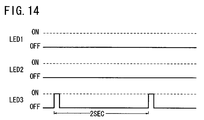
- FIG. 14 is a timing chart showing an indicator on/off pattern at the time of a drop in the power supply voltage
- FIGS. 15 and 16 are a flowchart of a timer routine
- FIG. 17 is a timing chart showing the relationship between a current supplied to the heater when the duty ratio is 40% and the count of a heater control period counter;
- FIG. 18 is a table showing the relationship between amount-of-current level parameter values, indicator turn-on states, and amounts of current supplied to the heater.
- FIG. 19 is a graph showing temperature increasing characteristics of the heater whose heater element is made of stainless steel foil.
- FIGS. 1 through 19 An apparatus for and a method of controlling the amount of current in a grip heater according to an embodiment of the present invention will be described below with reference to FIGS. 1 through 19 .
- the terms “left” and “right” or similar terms are referred to as directions as seen from the driver seated on a seat 32 (see FIG. 1 )
- the term “forward” or similar terms are referred to as a direction in which a motorcycle 12 (see FIG. 1 ) moves forwardly
- the term “rearward” or similar terms are referred to as a direction in which the motorcycle 12 moves rearwardly.
- a grip heater controlling apparatus 10 is mounted on a steering handle 14 of a motorcycle (vehicle) 12 near a left handlebar 16 a thereof.
- the grip heater controlling apparatus 10 serves to control the amount of current supplied to a grip heater 52 (see FIG. 3 ) which is mounted in each of a handle grip 18 a on the left handlebar 16 a and a handle grip 18 b on a right handlebar 16 b.
- the motorcycle 12 has a front fork 20 supporting a front wheel and angularly movably supported on a motorcycle frame, and a head lamp 22 and winker or direction indicator lamps 24 a , 24 b which are mounted on an upper portion of the front fork 20 .
- the winker lamps 24 a , 24 b are provided on both sides of the front fork 20 , respectively.
- the steering handle 14 with instruments 26 such as a speedometer, etc. mounted thereon is supported on the upper end of the front fork 20 .
- a clutch lever 28 is mounted on the left handlebar 16 a
- a brake lever 30 is mounted on the right handlebar 16 b .
- the motorcycle 12 also has a seat 32 for the driver to be seated thereon and a 12-V battery (power supply) 34 disposed below the seat 32 .
- the battery 34 is a lead battery.
- a terminal voltage of the battery 34 is set to be slightly higher than 12.0 V in view of wire resistance or the like.
- the grip heater controlling apparatus 10 is in the form of a single unit and comprises a box-shaped housing 40 of synthetic resin and a cable 42 extending from a side panel of the housing 40 .
- the housing 40 is mounted on the left handlebar 16 a by screws inserted through screw holes defined in a lower panel of the housing 40 .
- the housing 40 supports on its upper panel a momentary switch 44 positioned in a left region thereof and an indicator 45 positioned in a right region thereof and having three light-emitting diodes LED 1 , LED 2 , LED 3 .
- the switch 44 and the light-emitting diodes LED 1 , LED 2 , LED 3 are actually mounted on a board disposed in the housing 40 .
- the switch 44 has a water-resistant rubber sheet disposed as a switch operating member on the upper panel of the housing 40 , and the light-emitting diodes LED 1 , LED 2 , LED 3 have respective light guides disposed on the upper panel of the housing 40 .
- the switch 44 is illustrated as having the switch operating member which projects upwardly, the switch 44 may comprise any of various other switches such as a switch whose internal switch mechanism is operable through a planar sheet, or a membrane switch.
- the three light-emitting diodes LED 1 , LED 2 , LED 3 are arrayed in line on the upper panel of the housing 40 .
- the upper panel of the housing 40 is printed with letters “HI”, which stands for “HIGH”, adjacent to the light-emitting diode LED 1 , and letters “LO”, which stands for “LOW”, adjacent to the light-emitting diode LED 3 .
- the cable 42 has its distal end branched into three harness wires having a power supply terminal 46 a , a ground terminal 46 b , and a heater terminal 46 c , respectively.
- the grip heater controlling apparatus 10 is mounted on the left handlebar 16 a and the switch 44 is positioned in the left region of the upper panel of the housing 40 , the driver seated on the seat 32 can easily operate the switch 44 . Basically, the driver can operate the switch 44 with one finger simply by pressing the switch 44 , rather than holding or turning the switch 44 with two fingers for operating a potentiometer or the like.
- the left hand of the driver does not cover the light-emitting diodes LED 1 , LED 2 , LED 3 of the indicator 45 , and the driver can easily confirm the state of the light-emitting diodes LED 1 , LED 2 , LED 3 .
- the light-emitting diodes LED 1 , LED 2 , LED 3 are positioned in the right region of the upper panel of the housing 40 , they are close to the instruments 26 .
- the housing 40 is disposed closely to the right end of the left handle grip 18 a , and the cable 42 extends from the right side panel of the housing 40 .
- the cable 42 does not interfere with the left handle grip 18 a .
- the grip heater controlling apparatus 10 can easily be operated as it has not other manually manipulated elements than the switch 44 . Details of how the grip heater controlling apparatus 10 is operated will be described later on.
- the handle grip 18 a on the left handlebar 16 a has a cylindrical grip tube 50 , a grip heater 52 disposed in the grip tube 50 , an end cap 54 mounted on an end of the grip tube 50 , a cable cover 56 mounted on an upper portion of the other end of the grip tube 50 , and a cable 58 extending rearwardly from the cable cover 56 .
- the cable cover 56 is of such a shape that it projects progressively radially outwardly from a forward side toward an upper side of the other end of the grip tube 50 .
- the cable 58 extends from an end of the cable cover 56 .
- the end of the cable 58 which extends from the cable cover 56 is divided into two harness wires 59 a , 59 b having respective terminals 60 a , 60 b .
- the harness wires 59 a , 59 b have respective ends electrically connected to a heater element 62 of the grip heater 52 in the grip tube 50 .
- a core 64 is disposed in the grip tube 50 and has anchors 66 disposed on front sides of the opposite ends of the core 64 .
- the grip heater 52 has holes 67 defined in opposite ends thereof.
- the anchors 66 of the core 64 are fitted respectively in the holes 67 , thereby positioning the grip heater 52 with respect to the core 64 .
- the end cap 54 is mounted on an outer end of the core 64 , and two guides 68 a , 68 b of synthetic resin are mounted on the other inner end of the core 64 .
- the guides 68 a , 68 b serve as an inner base of the cable cover 56 (see FIG. 3 ), and also serve to protect and guide the cable 58 .
- a rubber grip layer on the handle grip 18 a is omitted from illustration.
- the grip heater 52 , the end cap 54 , the guides 68 a , 68 b , and the cable 58 are assembled on the grip tube 50 , a rubber grip layer is formed on the assembly, producing the handle grip 18 a.
- the grip heater 52 is in the form of a horizontally elongate film assembly comprising the heater element 62 sandwiched between two PET (PolyEthylene Terephthalate resin) films.
- the grip heater 52 is wound on and fixed to a front area of the core 64 .
- the grip heater 52 covers only the front area of the core 64 , it can heat fingertips of the left hand of the driver because the fingertips are placed on the front area of the handle grip 18 a when the driver grips the handle grip 18 a .
- the fingertips are sensitive to low temperatures and tend to be cooled by the wind when they are placed on the front area of the handle grip 18 a .
- the fingertips are heated by the grip heater 52 that is placed on the front area of the core 64 .
- the heater element 62 comprises a single slender stainless steel foil, and is disposed in a meandering pattern without crossings and overlaps on a substantially front area of the grip heater 52 .
- the heater element 62 has opposite ends disposed near the cable cover 56 and electrically connected to the ends of the harness wires 59 a , 59 b.
- the handle grip 18 b is of a structure basically identical to the handle grip 18 a , and has a grip heater 52 disposed in a front area thereof for heating fingertips of the right hand of the driver.
- the handle grips 18 a , 18 b have their orientations adjustable with respect to the left and right handlebars 16 a , 16 b.
- the cable cover 56 is disposed on the upper portion of the handle grip 18 a on the left handlebar 16 a .
- This layout is preferable because the handle grip 18 a is not rotated for accelerator control.
- an ignition switch (power supply switch) 70 of the motorcycle 12 has an input terminal connected through a main fuse 72 to the positive terminal of a battery 34 and also connected through a rectifying circuit 74 to an alternator (power supply) 76 .
- the alternator 76 is rotated by the unillustrated engine of the motorcycle 12 to generate AC power, which is rectified by the rectifying circuit 74 into DC power that is supplied to the ignition switch 70 and to the battery 34 , thus charging the battery 34 .
- the battery 34 has a negative terminal connected through a ground line G to the ground terminal 46 b .
- the motorcycle frame may serve as part of the ground line G.
- the ignition switch 70 has an output terminal connected through an auxiliary fuse 78 to the power supply terminal 46 a and also to the terminal 60 a of the harness wire 59 a on the left handlebar 16 a .
- the terminal 60 b of the harness wire 59 b on the left handlebar 16 a is connected to a terminal 60 c of a harness wire on the right handlebar 16 b , which is connected to one terminal of the grip heater 52 on the right handlebar 16 b . Therefore, the grip heater 52 on the left handlebar 16 a is connected in series to the grip heater 52 on the right handlebar 16 b .
- a terminal 60 d of a harness wire on the right handlebar 16 b which is connected to the other terminal of the grip heater 52 on the right handlebar 16 b , is connected to the heater terminal 46 c.
- the power supply terminal 46 a is connected to an output contact point for an ignition circuit, which is connected to a spark plug via, for example, a CDI (Capacitive Discharge Ignition) 79 (or an ignition coil or the like).
- CDI Capacitive Discharge Ignition
- the grip heater controlling apparatus 10 is supplied with electric power at a power supply voltage V 0 from the battery 34 .
- the grip heater controlling apparatus 10 is supplied with electric power at the power supply voltage V 0 from the battery 34 and the alternator 76 .
- the power supply voltage V 0 varies depending on the charged state of the battery 34 and the operating state of the alternator 76 .
- the housing 40 of the grip heater controlling apparatus 10 houses therein a CPU (Central Processing Unit, amount-of-current controller) 80 as a main controller, an oscillating circuit 82 having a quartz oscillator 82 a for supplying a control clock signal to the CPU 80 , a WDT (Watch Dog Timer) 84 for monitoring operation of the CPU 80 , an input interface 86 of the switch 44 , a power supply voltage monitoring circuit 88 for checking the power supply voltage V 0 , and a regulator 90 for generating IC power to be supplied to the integrated circuit of the CPU 80 .
- the CPU 80 may comprise a one-chip microcomputer.
- the housing 40 also houses therein an NPN-type field-effect transistor 92 serving as a current output component for supplying a current to the grip heaters 52 , and transistors 94 a , 94 b , 94 c for energizing the light-emitting diodes LED 1 , LED 2 , LED 3 .
- the WDT 84 monitors pulses that are periodically output from an output port P 5 of the CPU 80 . If the CPU 80 suffers a failure and is unable to generate pulses for a predetermined period of time, then the WDT 84 supplies a predetermined signal to a reset port P 10 of the CPU 80 , resetting the CPU 80 .
- the input interface 86 comprises a pull-up resistor 96 inserted between one terminal of the switch 44 and the regulator 90 , and a filter 98 for stabilizing a signal from the switch 44 .
- the input interface 86 is connected to an input port P 7 of the CPU 80 .
- the power supply voltage monitoring circuit 88 has a voltage-dividing resistor circuit 100 for dividing the power supply voltage V 0 , a protective diode 102 for preventing a voltage greater than the IC power from being applied, and a filter 104 for stabilizing a signal to be applied to the CPU 80 .
- the power supply voltage monitoring circuit 88 is connected to an analog input terminal P 6 of the CPU 80 .
- the regulator 90 converts the voltage that is supplied via the power supply terminal 46 a into the IC power of 5 V.
- the regulator 90 is protected by the protective diode 106 .
- the light-emitting diodes LED 1 , LED 2 , LED 3 have respective anodes connected through a protective diode 108 to the power supply terminal 46 a , and respective cathodes connected through respective current-limiting resistors 110 a , 110 b , 110 c to the collector terminals of respective transistors 94 a , 94 b , 94 c .
- the transistors 94 a , 94 b , 94 c have respective emitter terminals connected to ground, so that the transistors 94 a , 94 b , 94 c are emitter-grounded.
- the transistors 94 a , 94 b , 94 c have respective base terminals connected respectively to output ports P 1 , P 2 , P 3 of the CPU 80 . Therefore, the light-emitting diodes LED 1 , LED 2 , LED 3 can be energized and de-energized when the output ports P 1 , P 2 , P 3 are turned on and off. Furthermore, the luminance of light emitted from the light-emitting diodes LED 1 , LED 2 , LED 3 can be controlled when the periods of time for which the output ports P 1 , P 2 , P 3 are turned on and off are controlled in small time intervals.
- the field-effect transistor 92 has a drain terminal connected through the heater terminal 46 c to the grip heaters 52 , a source terminal connected to ground and also connected through a protective diode 112 to the drain terminal thereof, and a gate terminal connected to an output port P 4 of the CPU 80 . Therefore, the grip heaters 52 can be turned on and off when the output port P 4 is turned on and off. The amount of current supplied to the grip heaters 52 can continuously be controlled when the periods of time for which the output port P 4 is turned on and off are controlled in small time intervals.
- the CPU 80 has input/output ports P 8 , P 9 are connected to respective pins 114 , 116 on the board. If a certain communication unit is connected to the pins 114 , 116 , the communication unit can communicate with the CPU 80 . If the CPU 80 is set to a certain communication mode while it is being connected to the communication unit, a program can be loaded from the communication unit into a nonvolatile recording unit such as a flash memory or the like in the CPU 80 . The CPU 80 can then read and execute the program. It is also possible to write a program into the nonvolatile recording unit in the CPU 80 before it is mounted on the board.
- a nonvolatile recording unit such as a flash memory or the like
- a control process of controlling the amount of current supplied to the grip heaters 52 mounted on the handle grips 18 a , 18 b with the grip heater controlling apparatus 10 will be described below with reference to FIGS. 6 through 19 .
- FIGS. 6 , 7 , 8 , 9 , 10 , 11 , 15 , and 16 show processing sequences to be carried out by the CPU 80 based on the program stored in the nonvolatile recording unit. Unless otherwise noted, the processing sequences are executed in the order of step numbers.
- the grip heater controlling apparatus 10 When the driver inserts the key into the ignition switch 70 and turns the key, the grip heater controlling apparatus 10 is supplied with electric power from the battery 34 , and the CPU 80 starts operating.
- the CPU 80 reads the program from the nonvolatile recording unit and executes the program successively from a starting address, thereby executing a main routine shown in FIG. 6 and a timer routine shown in FIGS. 15 and 16 parallel to each other.
- the main routine is cyclically executed at a period of 10 msec. based on a main period monitoring flag Fmain that is set in the timer routine, and the timer routine is executed cyclically at a period of 100 ⁇ sec.
- FIGS. 7 through 11 show subroutines that are called from the main routine.
- the main routine and the subroutines that are called from the main routine will first be described below, and then the timer routine will be described later on.
- the subroutine of an initializing process (see FIG. 7 ) is executed in step S 1 shown in FIG. 6 .
- the main period monitoring flag Fmain is controlled by the timer routine such that it is set to “1” every 10 msec.
- step S 3 (voltage monitor), the subroutine of a power supply voltage detecting process (see FIG. 8 ) is executed.
- step S 4 the subroutine of a switch signal inputting process (see FIG. 9 ) is executed.
- step S 5 the subroutine of a grip heater current outputting process (see FIG. 10 ) is executed.
- step S 6 the subroutine of an indicator signal outputting process (see FIG. 11 ) is executed.
- step S 7 the main period monitoring flag Fmain is reset to 0 (Fmain ⁇ 0). Then, control goes back to step S 2 .
- step S 1 the initializing process in step S 1 is executed, and then the subroutines in steps S 3 through S 6 are executed every 10 msec. while referring to the value of the main period monitoring flag Fmain.
- step S 1 shown in FIG. 6 The subroutine of the initializing process in step S 1 shown in FIG. 6 will be described below with reference to FIG. 7 .
- various counters for measuring time are initialized in step S 101 .
- a main period counter Cmain for main routine control a time counter Con for indicating an on-state duration, a period counter Cpwm for heater control, a period counter CL for LED control, and a counter Cmsk for confirming a masking time, etc. are initialized.
- step S 102 eight buffers for storing sampled values of the power supply voltage are initialized to respective maximum values.
- step S 103 a storage area for storing the sum of data from the eight buffers is initialized to the sum of the maximum values stored in the respective buffers.
- the buffers for storing sampled values of the power supply voltage and the storage area for storing the sum of data from those buffers are initialized to the maximum values (FFH if they are 8-bit data).
- the ignition switch 70 is turned on, since the sampled values and the sum thereof are maximum, the power supply voltage V 0 is not judged as dropping at an initial stage in the subsequent power supply voltage detecting process (step S 3 in FIG. 6 ).
- step S 103 the subroutine of the initializing process is put to an end, and control goes back to the main routine.
- step S 3 The subroutine of the power supply voltage detecting process in step S 3 ( FIG. 6 ) will be described below with reference to FIG. 8 .
- the power supply voltage V 0 is divided and input in step S 201 . Specifically, a voltage divided from the power supply voltage V 0 by the voltage-dividing resistor circuit 100 is applied to the analog input port P 6 of the CPU 80 , which converts the divided voltage into a digital value and reads the digital voltage.
- step S 202 the read digital voltage is temporarily stored in a predetermined address of RAM (Random Access Memory).
- RAM Random Access Memory
- step S 203 a storage buffer which has stored the digital voltage converted eight cycles ago is specified by a ring buffer pointer Bp.
- step S 204 the value stored in the storage buffer specified in step S 203 , i.e., the digital voltage converted eight cycles ago, is saved to a saving address of RAM.
- step S 205 the digital voltage stored in the RAM in step S 202 is stored into the storage buffer specified in step S 203 .
- step S 206 the ring buffer pointer Bp is incremented to Bp ⁇ Bp+1.
- step S 207 it is determined whether or not the ring buffer pointer Bp is 8 or greater. If Bp ⁇ 8, then control goes to step S 208 . If Bp ⁇ 8, then control goes to step S 209 .
- step S 208 the ring buffer pointer Bp is reset to Bp 0. Therefore, the ring buffer pointer Bp takes a value in the range from 0 to 7 through the processing in steps S 206 through S 208 .
- the fourth and higher bits of the ring buffer pointer Bp may be masked, and the third and lower bits thereof may be used as valid bits to allow the ring buffer pointer Bp to take a value in the range from 0 to 7.
- step S 209 a moving average value Vave of the digital voltages is calculated. Specifically, the digital voltage saved to the saving RAM in step S 204 , i.e., the digital voltage converted eight cycles ago, is subtracted from the value stored in the storage area for storing the sum of data from the buffers, and the digital voltage stored in the storage buffer in step S 205 , i.e., the preset digital voltage, is added to the value stored in the storage area. In this manner, the moving average value Vave of the digital voltages can be determined highly accurately through a simple process free of divisions without bit canceling.
- the moving average value Vave is eight times greater than the voltage divided from the power supply voltage V 0 .
- the moving average value Vave can be used as a substantial average value to determine the value of the power supply voltage V 0 because it is of a smoothed value determined with respect to the power supply voltage V 0 .
- step S 210 it is determined whether or not the moving average value Vave is equal to or higher than a threshold Vth 1 (second threshold) which corresponds to 12.8 V. If Vave ⁇ Vth 1 , i.e., if V 0 ⁇ 12.8, then control goes to step S 211 . If Vave ⁇ Vth 1 , i.e., if V 0 ⁇ 12.8, then control goes to step S 212 .
- Vth 1 second threshold
- step S 211 a voltage judging flag Fbat is reset to Fbat ⁇ 0, indicating that the power supply voltage V 0 is normal. Then, the subroutine of the power supply voltage detecting process in the present cycle is put to an end.
- step S 212 it is determined whether or not the moving average value Vave is equal to or lower than a threshold Vth 2 (first threshold, Vth 2 ⁇ Vth 1 ) which corresponds to 12.0 V. If Vave ⁇ Vth 2 , i.e., if V 0 ⁇ 12.0, then control goes to step S 213 .
- step S 213 the voltage judging flag Fbat is set to Fbat ⁇ 1, indicating that the power supply voltage V 0 is lowered.
- step S 213 the subroutine of the power supply voltage detecting process in the present cycle is put to an end.
- step S 212 If Vave ⁇ Vth 1 , i.e., if V 0 >12.0, in step S 212 , then, the subroutine of the power supply voltage detecting process in the present cycle is put to an end.
- the voltage judging flag Fbat when the power supply voltage V 0 drops below 12.0 V, the voltage judging flag Fbat is set to Fbat ⁇ 1.
- the CPU 80 continuously turns on or off the indicator 45 to indicate the amount of current when the power supply voltage V 0 exceeds the threshold Vth 1 , and flickers at least a portion of the indicator 45 when the power supply voltage V 0 is equal to or less than the threshold Vth 2 .
- the CPU 80 actuates the indicator 45 to indicate a state based on the hysteretic characteristics when the power supply voltage V 0 exceeds the threshold Vth 2 and is equal to or less than the threshold Vth 1 .
- the driver can easily recognize when the grip heater 52 is de-energized due to a drop in the power supply voltage V 0 .
- the indicator 45 can be used to indicate both the amount of current and a drop in the power supply voltage V 0 . Further, due to the hysteretic performance, the voltage judging flag Fbat does not change too frequently, but operates stably.
- the moving average value Vave corresponds to the storage area for storing the sum of data in step S 103 , and is initialized to its maximum value in the initializing process. Consequently, the answer to step S 210 is affirmative when the subroutine of the power supply voltage detecting process is executed for the first time. If the power supply voltage V 0 is of a normal value, then the voltage judging flag Fbat is not set to Fbat ⁇ 1 in the initializing process.
- step S 4 The subroutine of the switch signal inputting process in step S 4 (see FIG. 6 ) will be described below with reference to FIG. 9 .
- a switch signal logic value is sampled in step S 301 . Specifically, the on or off state of the switch 44 is read through the input port P 7 .
- step S 302 a parameter indicative of the on or off state of the switch 44 which is read in step S 301 is stored into a sampling buffer.
- step S 303 the values of parameters stored in the sampling buffer are checked. If the values of all the latest four parameters represent the on state of the switch 44 , then control goes to step S 304 . If even one of the values of all the latest four parameters represents the off state of the switch 44 , then control goes to step S 305 .
- step S 304 a flag Fin_new indicative of the present state of the switch 44 is set to Fin_new ⁇ 1, indicating that the switch 44 is turned on. Thereafter, control goes to step S 307 .
- step S 304 the on-state of the switch 44 is confirmed by the flag Fin_new set to Fin_new ⁇ 1.
- step S 305 the values of parameters stored in the sampling buffer are checked. If the values of all the latest four parameters represent the off state of the switch 44 , then control goes to step S 306 . If even one of the values of all the latest four parameters represents the on state of the switch 44 , then control goes to step S 307 .
- steps S 303 , S 305 the flag Fin_new is set or reset only when the on or off state is confirmed in four successive cycles. Therefore, even if noise is applied to the input port P 7 , the grip heater controlling apparatus 10 is prevented from malfunctioning due to the noise.
- step S 306 the flag Fin_new is set to Fin_new ⁇ 0, indicating that the switch 44 is turned off.
- step S 306 the off-state of the switch 44 is confirmed by the flag Fin_new set to Fin_new ⁇ 0.
- step S 308 the time counter Con which is to be decremented is set to Con ⁇ 1000.
- step S 309 a switch failure judging flag Ffail is reset to Ffail ⁇ 0.
- step S 311 the switch failure judging flag Ffail is set to Ffail ⁇ 1, indicating that the switch 44 is suffering a failure. That is, because the on-time of the switch 44 in a single turn-on cycle is usually less than 10 sec., the switch 44 can be judged as failing if it is continuously turned on for 10 sec.
- step S 312 the timer counter Con is decremented by Con ⁇ Con ⁇ 1.
- step S 313 after steps S 309 , S 311 , S 312 , an on-edge detecting flag Fswon is reset to Fswon ⁇ 0.
- step S 315 a time at which the switch 44 is turned on successively four times or more after the switch 44 has been turned off successively four times or more is detected as a switch-on edge.
- the flag Fin_new that is set and reset in steps S 304 , S 306 and a flag Fin_old, which represents the value in a preceding cycle of the flag Fin_new, are exclusive-ORed, and the result of the exclusive-ORing process and the flag Fin_new are ANDed.
- the result of the ANDing process is put into a temporary flag Fa.
- step S 317 the on-edge detecting flag Fswon is set to Fswon ⁇ 1.
- step S 318 the present switch state data is saved. Specifically, the flag Fin_new is saved as Fin_old ⁇ Fin_new to Fin_old. After step S 318 , the subroutine of the switch signal inputting process is ended.
- step S 5 The subroutine of the grip heater current outputting process in step S 5 (see FIG. 6 ) will be described below with reference to FIG. 10 .
- step S 401 the counter Cmsk for confirming a masking time which is initialized in step S 101 is decremented (Cmsk ⁇ Cmsk ⁇ 1 ) if Cmsk>0.
- step S 402 it is determined whether a predetermined masking time has elapsed or not. Since the power supply voltage V 0 may not be stable immediately after the ignition switch 70 is turned on, a masking process is performed to keep the grip heaters 52 de-energized even if the switch 44 is operated. Specifically, if the value of the counter Cmsk is 0, then it is judged that the masking time (e.g., 100 msec.) has elapsed, and control goes to step S 404 . If Cmsk>0, then it is judged that the masking time has not yet elapsed, and control goes to step S 403 .
- the masking time e.g. 100 msec.
- step S 403 an amount-of-current level parameter Lv is reset to Lv ⁇ 0.
- the amount-of-current level parameter Lv represents the level of an amount of current supplied to the grip heaters 52 , and is cyclically set to six integers ranging from 0 to 5. Immediately after the ignition switch 70 is turned on, the amount-of-current level parameter Lv is set to 0. After step S 403 , control goes to step S 411 .
- step S 405 the grip heaters 52 are de-energized. Specifically, a heater duty ratio value D 1 for controlling the amount of current supplied to the grip heaters 52 is set to 0, turning off the grip heaters 52 . Thereafter, the subroutine of the grip heater current outputting process in the present cycle is put to an end.
- step S 405 the value of the amount-of-current level parameter Lv is maintained. Therefore, when the power supply voltage V 0 returns to 12.8 V or higher again, the energization of the grip heaters 52 is automatically resumed based on the amount-of-current level parameter Lv at the time the power supply voltage V 0 drops to 12.0 V or lower.
- control goes to step S 405 , turning off the grip heaters 52 .
- step S 408 the amount-of-current level parameter Lv is decremented to Lv ⁇ Lv ⁇ 1.
- step S 409 the value of the amount-of-current level parameter Lv is checked. If Lv ⁇ 0, then control goes to step S 410 . Otherwise, control goes to step S 411 .
- step S 410 the amount-of-current level parameter Lv is set to Lv ⁇ 5. Thereafter, control goes to step S 411 .
- the amount of current supplied to the grip heaters 52 is set a value depending on the six-stage value of the amount-of-current level parameter Lv. If the amount-of-current level parameter Lv is 4, 3, 2, and 1, the duty ratio of the grip heaters 52 is set to 80%, 60%, 40%, and 20%, respectively, and the heater duty ratio value D 1 is set 80, 60, 40, and 20, respectively. Therefore, the heater duty ratio value D 1 may be set to the same value as the duty ratio.
- step S 411 the subroutine of the grip heater current outputting process is ended.
- the amount-of-current level parameter Lv is cyclically set to 0 ⁇ 5 ⁇ 4 ⁇ 3 ⁇ 2 ⁇ 1 ⁇ 0 . . . .
- the amount-of-current level parameter Lv is set to 5, and the amount of current supplied to the grip heaters 52 is maximized. Accordingly, the handle grips 18 a , 18 b can quickly be heated by a simple action.
- the driver feels adequately warm or slightly too hot on the handle grips 18 a , 18 b , since the amount-of-current level parameter Lv is set to 4, 3, 2, 1, 0, successively, each time the driver operates the switch 44 , the amount of current supplied to the grip heaters 52 can be reduced as desired by the driver. If the driver wants to reheat the handle grips 18 a , 18 b , then the driver may operate the switch 44 to set the amount-of-current level parameter Lv to 5. As described later on, the driver can visually recognize the value of the amount-of-current level parameter Lv, i.e., the amount of current supplied to the grip heaters 52 , with the light-emitting diodes LED 1 , LED 2 , LED 3 .
- the driver can easily set the amount-of-current level parameter Lv by operating the single switch 44 . Since the amount-of-current level parameter Lv is cyclically set to six values including 0, the grip heaters 52 can be energized and de-energized, and the amount of current supplied thereto can be adjusted, all by the single switch 44 .
- step S 6 The subroutine of the indicator signal outputting process in step S 6 (see FIG. 6 ) will be described below with reference to FIG. 11 .
- step S 503 energization patterns of the light-emitting diodes LED 1 , LED 2 , LED 3 are set depending on the value of the amount-of-current level parameter Lv established in the subroutine of the grip heater current outputting process (see FIG. 10 ). Specifically, a duty ratio value D L1 representative of the energization pattern of the light-emitting diode LED 1 , a duty ratio value D L2 representative of the energization pattern of the light-emitting diode LED 2 , and a duty ratio value D L3 representative of the energization pattern of the light-emitting diode LED 3 are set based on a table shown in FIG. 12 .
- the duty ratio values D L1 , D L2 , D L3 are set to D L1 ⁇ 0, D L2 ⁇ 0, D L3 ⁇ 0.
- the duty ratio values D L1 , D L2 , D L3 are set to D L1 ⁇ 100, D L2 ⁇ 100, D L3 ⁇ 100.
- the duty ratio values D L1 , D L2 , D L3 are set to D L1 ⁇ 10, D L2 ⁇ 100, D L3 ⁇ 100.
- the duty ratio values D L1 , D L2 , D L3 are set to D L1 ⁇ 0, D L2 ⁇ 100, D L3 ⁇ 100.
- the duty ratio values D L1 , D L2 , D L3 are set to D L1 ⁇ 0, D L2 ⁇ 10, D L3 ⁇ 100.
- the duty ratio values D L1 , D L2 , D L3 are set to D L1 ⁇ 0, D L2 ⁇ 0, D L3 ⁇ 100.
- step S 504 the light-emitting diodes LED 1 , LED 2 , LED 3 are flickered in periods of 1 sec. in a pattern indicating that the switch 44 is suffering a failure.
- the duty ratio values D L1 , D L2 , D L3 are set to D L1 ⁇ 0, D L2 ⁇ 0, D L3 ⁇ 0 to turn off the light-emitting diodes LED 1 , LED 2 , LED 3
- the duty ratio values D L1 , D L2 , D L3 are set to D L1 ⁇ 100, D L2 ⁇ 100, D L3 ⁇ 100, turning on the light-emitting diodes LED 1 , LED 2 , LED 3 .
- This process is repeated to cause the light-emitting diodes LED 1 , LED 2 , LED 3 to be flickered repeatedly, i.e., turned on in 500 msec. of every 1 sec. and turned off in remaining 500 msec., as shown in FIG. 13 .
- step S 505 the light-emitting diode LED 3 is flickered in periods of 2 sec. in a pattern indicating that the power supply voltage V 0 is lowered, and the light-emitting diodes LED 1 , LED 2 are turned off.
- the duty ratio values D L1 , D L2 are set to D L1 ⁇ 0, D L2 ⁇ 0 to turn off the light-emitting diodes LED 1 , LED 2 .
- step S 505 the duty ratio value D L3 is set to D L3 ⁇ 0, turning off the light-emitting diode LED 3 , and in next successive 10 cycles, the duty ratio value D L3 is set to D L3 ⁇ 100, turning on the light-emitting diode LED 3 .
- This process is repeated to cause the light-emitting diode LED 3 to be flickered repeatedly, i.e., turned on in 100 msec. of every 2 sec. and turned off in remaining 1900 msec., as shown in FIG. 14 .
- steps S 504 , S 505 inasmuch as those to be turned on and off of the light-emitting diodes LED 1 , LED 2 , LED 3 and their energization patterns are clearly different from each other. Therefore, the driver can reliably distinguish a failure of the switch 44 and a reduction in the power supply voltage V from each other.
- the energization patterns of the light-emitting diodes LED 1 , LED 2 , LED 3 while the grip heaters 52 are energized normally normally are turned on and off continuously, and are clearly different from the energization patterns thereof upon a failure of the switch 44 and a reduction in the power supply voltage V. Consequently, the driver can easily recognize a failure of the switch 44 and a reduction in the power supply voltage V from the light-emitting diodes LED 1 , LED 2 , LED 3 .
- the timer routine which executed every 100 ⁇ sec. will be described below with reference to FIGS. 15 and 16 .
- step S 601 the main period counter Cmain for main routine control is decremented to Cmain ⁇ Cmain ⁇ 1.
- step S 603 the main period counter Cmain is initialized again to Cmain ⁇ 100.
- step S 604 the main period monitoring flag Fmain is set to Fmain ⁇ 1, allowing the main routine (see FIG. 6 ) to be executed. Steps S 6 through S 7 of the main routine are thus executed every 10 msec.
- step S 605 the period counter Cpwm for heater control is decremented to Cpwm ⁇ Cpwm ⁇ 1.
- step S 607 the period counter Cpwm is initialized again to Cpwm ⁇ 100.
- step S 608 the value of the period counter Cpwm is compared with the heater duty ratio value D 1 . If Cpwm ⁇ D 1 , then control goes to step S 610 . If Cpwm>D 1 , then control goes to step S 609 .
- step S 609 the grip heaters 52 are de-energized. Specifically, the output port P 4 outputs a signal to turn off the field-effect transistor 92 , de-energizing the grip heaters 52 .
- step S 610 the grip heaters 52 are energized. Specifically, the output port P 4 outputs a signal to turn on the field-effect transistor 92 , energizing the grip heaters 52 .
- the heater duty ratio value D 1 is 40, for example, then when 100 ⁇ Cpwm>40, as shown in FIG. 17 , the grip heaters 52 are de-energized, and when 40 ⁇ Cpwm, the grip heaters 52 are energized at a duty ratio of 40%. If the heater duty ratio value D 1 is 0, then the grip heaters 52 are de-energized. If the heater duty ratio value D 1 is 20, 40, 60, 80, and 100, the grip heaters 52 are energized by corresponding currents (see FIG. 18 ).
- step S 611 shown in FIG. 16 the period counter CL for LED control is decremented to CL ⁇ CL ⁇ 1.
- step S 613 the period counter CL is initialized again to CL ⁇ 100.
- step S 614 the value of the period counter CL is compared with the duty ratio value D L3 representative of the energization pattern of the light-emitting diode LED 3 . If CL ⁇ D L3 , then control goes to step S 616 . If CL>D L3 , then control goes to step S 615 .
- step S 615 the light-emitting diode LED 3 is turned off. Specifically, the output port P 3 outputs a signal to turn off the transistor 94 c , turning off the light-emitting diode LED 3 . Thereafter, control goes to step S 617 .
- step S 616 the light-emitting diode LED 3 is turned on. Specifically, the output port P 3 outputs a signal to turn on the transistor 94 c , turning on the light-emitting diode LED 3 . Thereafter, control goes to step S 617 .
- step S 617 the value of the period counter CL is compared with the duty ratio value D L2 representative of the energization pattern of the light-emitting diode LED 2 . If CL ⁇ D L2 , then control goes to step S 619 . If CL>D L2 , then control goes to step S 618 .
- step S 618 the light-emitting diode LED 2 is turned off. Specifically, the output port P 2 outputs a signal to turn off the transistor 94 b , turning off the light-emitting diode LED 2 . Thereafter, control goes to step S 620 .
- step S 619 the light-emitting diode LED 2 is turned on. Specifically, the output port P 2 outputs a signal to turn on the transistor 94 b , turning on the light-emitting diode LED 2 . Thereafter, control goes to step S 620 .
- step S 620 the value of the period counter CL is compared with the duty ratio value D L1 representative of the energization pattern of the light-emitting diode LED 1 . If CL ⁇ D L1 , then control goes to step S 622 . If CL>D L1 , then control goes to step S 621 .
- step S 621 the light-emitting diode LED 1 is turned off. Specifically, the output port P 1 outputs a signal to turn off the transistor 94 a , turning off the light-emitting diode LED 1 .
- step S 622 the light-emitting diode LED 1 is turned on. Specifically, the output port P 1 outputs a signal to turn on the transistor 94 a , turning on the light-emitting diode LED 1 .
- the execution of the main routine is permitted based on the main period counter Cmain, and the amounts of current supplied to the grip heaters 52 and the light-emitting diodes LED 1 , LED 2 , LED 3 are controlled based on the value of the period counter Cpwm for heater control and the value of the period counter CL for LED control.
- duty ratios thereof are determined based on the heater duty ratio value D 1 , the duty ratio value D L1 , the duty ratio value D L2 , and the duty ratio value D L3 . Then, currents depending on the amount-of-current level parameter Lv, as shown in FIG. 18 , are supplied to the light-emitting diodes LED 1 , LED 2 , LED 3 . In FIG. 18 , the period T is set to 10 msec., as described above.
- the duty ratio of the light-emitting diode LED 1 is set to 10% based on the duty ratio value D L1 , the light-emitting diode LED 1 is turned on at an intermediate luminance level, and the light-emitting diodes LED 2 , LED 3 are fully turned on.
- the light-emitting diode LED 1 is turned on at an intermediate luminance level based on the duty ratio of 10%, it can clearly be visually distinguished from the light-emitting diodes LED 2 , LED 3 that are fully turned on, and can still reliably be visually perceived as being turned on.
- the driver can easily recognize the light-emitting diode LED 1 as being turned on at an intermediate luminance level.
- the duty ratio for turning on a light-emitting diode may be set to a value in the range from 5 to 20%.
- the light-emitting diode LED 2 is similarly turned on when the amount-of-current level parameter Lv is 2.
- the light-emitting diode LED 1 When the amount-of-current level parameter Lv is 3, the light-emitting diode LED 1 is turned off, and the light-emitting diodes LED 2 , LED 3 are fully turned on.
- the light-emitting diode LED 1 When the amount-of-current level parameter Lv is 2, the light-emitting diode LED 1 is turned off, the light-emitting diode LED 2 is turned on at an intermediate luminance level because the duty ratio thereof is set to 10% based on the duty ratio value D L2 , and the light-emitting diode LED 3 is fully turned on.
- the light-emitting diodes LED 1 , LED 2 are turned off, and the light-emitting diode LED 3 is fully turned on.
- the indicator 45 By thus individually fully turning on, fully turning off, and turning on at an intermediate luminance level the light-emitting diodes LED 1 , LED 2 , LED 3 , the six levels of the amount-of-current level parameter Lv can be expressed by the three light-emitting diodes. Since the indicator 45 has the three light-emitting diodes LED 1 , LED 2 , LED 3 , it can present eight combinations. Even if no intermediate luminance level turn-ons are employed, the indicator 45 can display six levels distinguishably.
- the driver is unable to grasp the amount-of-current level intuitively.
- the driver when at least one of the light-emitting diodes LED 1 , LED 2 , LED 3 is turned on at an intermediate luminance level, the driver can recognize the amount-of-current level intuitively.
- the light-emitting diodes LED 1 , LED 2 , LED 3 are arrayed in line and are successively turned on at an intermediate luminance level or fully turned on from an end of the array depending on the amount-of-current level.
- the light-emitting diodes as they are turned on are visually recognized as an elongate array of bright dots which looks like a bar graph, and the number of successive light-emitting diodes that are turned on at an intermediate luminance level or fully turned on gives the driver an intuitive grasp of the amount-of-current level.
- an array of bright dots produced by light-emitting diodes that are turned on which includes a light-emitting diode that is fully turned on at an end of the array enables the driver to recognize a higher amount-of-current level than an array of as many bright dots produced by light-emitting diodes that are turned on which includes a light-emitting diode that is turned on at an intermediate luminance level at an end of the array.
- the amount-of-current level parameter Lv takes six values from 0 to 5. If the light-emitting diode LED 3 is also turned on at an intermediate luminance level, then the amount-of-current level parameter Lv can be set to seven values, which allow practically sufficient levels to be displayed for identification. With such intermediate luminance level turn-ons, only three light-emitting diodes LED 1 , LED 2 , LED 3 are sufficient, making the housing inexpensive to manufacture and small in size, and allowing the indicator 45 to consume reduced electric power.
- the number of values that amount-of-current level parameter Lv takes may be three including 0.
- the light-emitting diode LED 1 may be dispensed with, and the light-emitting diodes LED 2 , LED 3 may be turned off when the amount-of-current level parameter Lv is 0, the light-emitting diodes LED 2 , LED 3 may be fully turned on when the amount-of-current level parameter Lv is 2, and the light-emitting diode LED 2 may be turned off and the light-emitting diode LED 3 may be fully turned on when the amount-of-current level parameter Lv is 1.
- the heater duty ratio value D 1 may be set, for example, to 0%, 100%, and 50%, respectively.
- the number of values that amount-of-current level parameter Lv takes is two, then it switches between on and off states only, and it is unable to adjust the amount of current. If the number of values that amount-of-current level parameter Lv takes is too large, the switch 44 needs to be operated too often for adjusting the amount of current and de-energizing the grip heaters 52 , and hence the operation of the switch 44 becomes complicated and time-consuming. Therefore, the number of values that amount-of-current level parameter Lv takes should appropriately be in the range from three to seven.
- the amount-of-current level parameter Lv is cyclically changed to six levels including “O” which indicates the de-energization of the grip heaters 52 , depending on the number of times that the momentary switch 44 is operated, the amount of current supplied to the grip heaters 52 can easily be controlled.
- the handle grips 18 a , 18 b can quickly be heated by a simple action.
- the heater element 62 (see FIG. 4 ) of the grip heaters 52 is made of stainless steel foil, the temperature thereof can rapidly be increased to heat the handle grips 18 a , 18 b quickly.
- a temperature increase caused by the heater element 62 made of stainless steel foil is represented by the solid-line curve 200 .
- the temperature increase has a rise time T 1 , which is measured according to predetermined standards, that is about one-quarter of a rise time T 2 of a temperature increase (represented by the broken-line curve 202 ) caused by a heater element made of copper foil.
- the grip heater controlling apparatus 10 stops energizing the grip heaters 52 . Therefore, a current load on the battery 34 and the alternator 76 , i.e., the power supply, is reduced.
- the grip heater controlling apparatus 10 detects a reduction in the power supply voltage V 0 and turns off the grip heaters 52 . Consequently, the motorcycle 12 maintains its ability to be started at low temperatures.
- the grip heater controlling apparatus 10 is operated by the single momentary switch 44 , it can be operated highly simply.
- the grip heater controlling apparatus 10 can be operated even if it is covered with a handle cover or the like.
- the switch 44 is simpler, more reliable and durable, and more inexpensive than potentiometers or the like.
- the switch 44 may be made lower in profile than potentiometers or the like, making it possible to construct the grip heater controlling apparatus 10 as a compact unit.
- the indicator 45 may comprise liquid-crystal display elements rather than light-emitting diodes.
Abstract
Description
Vb=(V0−0.64)/5 (1)
where the numerical value 0.64 represents a voltage drop caused by the
Claims (15)
Applications Claiming Priority (5)
| Application Number | Priority Date | Filing Date | Title |
|---|---|---|---|
| JP2004-042088 | 2004-01-18 | ||
| JP2004-42088 | 2004-01-18 | ||
| JP2004042088 | 2004-01-18 | ||
| JP2004337141A JP4138733B2 (en) | 2004-01-18 | 2004-11-22 | Grip heater control device and control method |
| JP2004-337141 | 2004-11-22 |
Publications (2)
| Publication Number | Publication Date |
|---|---|
| US20050173406A1 US20050173406A1 (en) | 2005-08-11 |
| US9024236B2 true US9024236B2 (en) | 2015-05-05 |
Family
ID=34622264
Family Applications (1)
| Application Number | Title | Priority Date | Filing Date |
|---|---|---|---|
| US11/035,810 Active 2027-04-09 US9024236B2 (en) | 2004-01-18 | 2005-01-18 | Apparatus for and method of controlling grip heater |
Country Status (5)
| Country | Link |
|---|---|
| US (1) | US9024236B2 (en) |
| EP (1) | EP1555198B1 (en) |
| JP (1) | JP4138733B2 (en) |
| CN (1) | CN100381328C (en) |
| DE (1) | DE602005001510T2 (en) |
Cited By (5)
| Publication number | Priority date | Publication date | Assignee | Title |
|---|---|---|---|---|
| US20150353156A1 (en) * | 2012-11-12 | 2015-12-10 | Indian Motorcycle International, LLC | Two-wheeled vehicle |
| US10760730B2 (en) | 2013-11-11 | 2020-09-01 | Indian Motorcycle International, LLC | Two-wheeled vehicle |
| US11066120B2 (en) * | 2017-11-06 | 2021-07-20 | Harley-Davidson Motor Company Group, LLC | Heated handgrips for a motorcycle |
| US11292542B2 (en) * | 2017-11-06 | 2022-04-05 | Harley-Davidson Motor Company Group, LLC | Independently heated handgrips for a motorcycle |
| US11634192B2 (en) * | 2020-12-11 | 2023-04-25 | Foshan Nanhai Saneagle Bicycle Co., Ltd | Bicycle handlebar |
Families Citing this family (19)
| Publication number | Priority date | Publication date | Assignee | Title |
|---|---|---|---|---|
| DE10141049C1 (en) * | 2001-08-22 | 2003-02-20 | Bayerische Motoren Werke Ag | Electrically-heated motorcycle handgrip has heating element supplied via coiled lead element allowing rotation of handgrip |
| US6998970B2 (en) * | 2004-02-03 | 2006-02-14 | Honda Motor Company, Ltd. | Turn signal assembly |
| DE102005014682A1 (en) * | 2005-03-29 | 2006-10-19 | Thomas Brehmer | Handle with heating device |
| US7064292B1 (en) * | 2005-04-01 | 2006-06-20 | Honda Access Corp. | Grip heater control apparatus |
| KR100886001B1 (en) | 2007-05-17 | 2009-03-03 | 남정우 | Wireless Cold-Proof Equipment with Heating Element |
| US8447436B2 (en) | 2010-06-29 | 2013-05-21 | Harley-Davidson Motor Company Group, LLC | Handlebar control system |
| IT1402381B1 (en) * | 2010-09-09 | 2013-09-04 | Domino Spa | HEATED HANDLE FOR EASY ASSEMBLY AND ADAPTATION TO HANDLEBARS OF DIFFERENT VEHICLES |
| DE102012203401A1 (en) * | 2012-03-05 | 2013-09-05 | Volkswagen Aktiengesellschaft | Method for controlling a heating device for heating a component, control device and motor vehicle with such |
| TWM466066U (en) * | 2013-07-23 | 2013-11-21 | Tong Yah Ind Co Ltd | Heated grip sheath |
| CN105723081A (en) * | 2013-11-11 | 2016-06-29 | 北极星工业有限公司 | Two-wheeled vehicle |
| JP5701369B1 (en) * | 2013-12-03 | 2015-04-15 | 株式会社日本ロック | Grip heater device for motorcycles |
| JP6388496B2 (en) * | 2014-06-06 | 2018-09-12 | 株式会社東海理化電機製作所 | Steering wheel structure |
| CN105799822A (en) * | 2014-12-30 | 2016-07-27 | 天津博利自行车有限公司 | Waist-warming bicycle |
| US20160291662A1 (en) * | 2015-04-03 | 2016-10-06 | Daniel Gino Grassetti | Integrated vehicle power distribution and control system |
| CN108011565B (en) * | 2016-11-02 | 2022-02-01 | 德昌电机(深圳)有限公司 | Motor application apparatus and control method thereof |
| CA176951S (en) | 2017-03-28 | 2018-06-28 | Faltec Co Ltd | Grip heater for a motorcycle |
| JP6853756B2 (en) * | 2017-09-05 | 2021-03-31 | 川崎重工業株式会社 | Grip heater device |
| US20210188383A1 (en) * | 2019-12-20 | 2021-06-24 | Polaris Industries Inc. | Snowmobile control system |
| DE102022113772A1 (en) | 2022-05-31 | 2023-11-30 | Supernova Design GmbH | Handle |
Citations (39)
| Publication number | Priority date | Publication date | Assignee | Title |
|---|---|---|---|---|
| US1546413A (en) * | 1924-05-31 | 1925-07-21 | Solomon Samuel | Steering-wheel heater |
| US4506145A (en) * | 1978-07-10 | 1985-03-19 | Isuzu Motors Ltd. | Device for controlling engine preheating |
| US4511097A (en) * | 1981-12-14 | 1985-04-16 | Nippon Soken, Inc. | Automobile seat belt winding device |
| JPS61146671A (en) | 1984-12-18 | 1986-07-04 | Daihatsu Motor Co Ltd | Hand warmer device for interior decoration parts for car |
| JPS6264610A (en) | 1985-09-18 | 1987-03-23 | Nippon Denso Co Ltd | Actuating device for on-vehicle air conditioner |
| JPS63132290A (en) | 1986-11-22 | 1988-06-04 | 株式会社明電舎 | Lamp display control by momentary type push button |
| US4944056A (en) * | 1988-09-28 | 1990-07-31 | The Research Foundation Of State University Of Ny | Method and apparatus for transporting a disabled person |
| JPH03231247A (en) | 1990-02-06 | 1991-10-15 | Dainippon Screen Mfg Co Ltd | Method for producing image contour data |
| JPH03254798A (en) * | 1990-03-02 | 1991-11-13 | Sanyo Electric Co Ltd | Iron |
| US5072098A (en) * | 1990-06-11 | 1991-12-10 | Chrysler Corporation | Electrically heated windshield controller |
| US5128661A (en) * | 1982-10-12 | 1992-07-07 | Robertshaw Controls Company | Solid state rotary entry control system |
| US5225974A (en) * | 1990-10-30 | 1993-07-06 | Allen-Bradley Company, Inc. | Programmable controller processor with an intelligent functional module interface |
| JPH0626661A (en) | 1992-07-09 | 1994-02-04 | Matsushita Electric Ind Co Ltd | Floor heating device |
| GB2287230A (en) | 1991-11-27 | 1995-09-13 | Brian Page Controls Ltd | Vehicle control system with a single switch controlling several functions |
| US5708244A (en) * | 1995-10-19 | 1998-01-13 | Conti; William S. | Handgrip switch assembly |
| US5718120A (en) | 1995-11-30 | 1998-02-17 | Zexel Corporation | Vehicle air-conditioning system and control method |
| JPH1079284A (en) * | 1996-09-03 | 1998-03-24 | Koito Mfg Co Ltd | Car heater control device |
| JPH1081284A (en) * | 1996-09-11 | 1998-03-31 | Koito Mfg Co Ltd | Controller of grip built-in heater for vehicle |
| US5757165A (en) * | 1996-01-11 | 1998-05-26 | Minks; Floyd M. | Snowmobile handlebar heater control |
| US5861610A (en) * | 1997-03-21 | 1999-01-19 | Micro Weiss Electronics | Heater wire with integral sensor wire and improved controller for same |
| JPH1189725A (en) | 1997-09-18 | 1999-04-06 | Zojirushi Vacuum Bottle Co | Electric pot |
| JPH11124077A (en) | 1997-10-22 | 1999-05-11 | Honda Motor Co Ltd | Motor-assisted bicycle |
| US6114668A (en) * | 1996-08-29 | 2000-09-05 | Koita Manufacturing Co., Ltd. | Heater-containing grip for vehicles |
| US20020005861A1 (en) * | 2000-04-12 | 2002-01-17 | Roger Lewis | Method, apparatus and computer program product for controlling LED backlights and for improved pulse width modulation resolution |
| JP2002096785A (en) | 2000-09-25 | 2002-04-02 | Terumi Wada | Bicycle handlebar heater system with battery |
| US6392316B1 (en) * | 2000-03-20 | 2002-05-21 | Matsushita Electric Industrial Co., Ltd. | Emergency informing apparatus |
| US6400564B1 (en) * | 2000-09-14 | 2002-06-04 | Shimano Inc. | Switch guide for a bicycle control panel |
| US20020158583A1 (en) * | 1997-08-26 | 2002-10-31 | Lys Ihor A. | Automotive information systems |
| US20030019734A1 (en) * | 2001-07-25 | 2003-01-30 | Teac Corporation | Switch device |
| US20030121903A1 (en) * | 2001-11-05 | 2003-07-03 | Baker Robert W. | Protective circuit for electrical heating element |
| US20030226836A1 (en) * | 2002-06-10 | 2003-12-11 | Kabushiki Kaisha Honda Access | Apparatus for controlling grip heater |
| EP1371544A1 (en) | 2002-06-10 | 2003-12-17 | Kabushiki Kaisha Honda Access | Apparatus for controlling grip heater |
| US20030231630A1 (en) * | 2001-08-30 | 2003-12-18 | Messenger Brian Scott | High speed data classification system |
| US20040007567A1 (en) | 2002-07-12 | 2004-01-15 | Downey Philip L. | Heated cycle grip |
| JP2004009969A (en) | 2002-06-10 | 2004-01-15 | Honda Access Corp | Control device of grip heater |
| US20040021427A1 (en) * | 2000-06-13 | 2004-02-05 | Bruwer Frederick Johannes | Intelligent switch for connecting power to a load |
| JP2004067076A (en) | 2002-06-10 | 2004-03-04 | Honda Access Corp | Grip heater control device |
| US20040195916A1 (en) * | 2003-04-02 | 2004-10-07 | Katrak Kerfegar K. | Methods and apparatus for producing a three-state single wire control |
| US20040263094A1 (en) * | 2003-06-30 | 2004-12-30 | Stephen Lister | Incremental color blending illumination system using LEDs |
-
2004
- 2004-11-22 JP JP2004337141A patent/JP4138733B2/en active Active
-
2005
- 2005-01-18 US US11/035,810 patent/US9024236B2/en active Active
- 2005-01-18 CN CNB2005100047530A patent/CN100381328C/en not_active Expired - Fee Related
- 2005-01-18 DE DE602005001510T patent/DE602005001510T2/en active Active
- 2005-01-18 EP EP05000926A patent/EP1555198B1/en not_active Expired - Fee Related
Patent Citations (39)
| Publication number | Priority date | Publication date | Assignee | Title |
|---|---|---|---|---|
| US1546413A (en) * | 1924-05-31 | 1925-07-21 | Solomon Samuel | Steering-wheel heater |
| US4506145A (en) * | 1978-07-10 | 1985-03-19 | Isuzu Motors Ltd. | Device for controlling engine preheating |
| US4511097A (en) * | 1981-12-14 | 1985-04-16 | Nippon Soken, Inc. | Automobile seat belt winding device |
| US5128661A (en) * | 1982-10-12 | 1992-07-07 | Robertshaw Controls Company | Solid state rotary entry control system |
| JPS61146671A (en) | 1984-12-18 | 1986-07-04 | Daihatsu Motor Co Ltd | Hand warmer device for interior decoration parts for car |
| JPS6264610A (en) | 1985-09-18 | 1987-03-23 | Nippon Denso Co Ltd | Actuating device for on-vehicle air conditioner |
| JPS63132290A (en) | 1986-11-22 | 1988-06-04 | 株式会社明電舎 | Lamp display control by momentary type push button |
| US4944056A (en) * | 1988-09-28 | 1990-07-31 | The Research Foundation Of State University Of Ny | Method and apparatus for transporting a disabled person |
| JPH03231247A (en) | 1990-02-06 | 1991-10-15 | Dainippon Screen Mfg Co Ltd | Method for producing image contour data |
| JPH03254798A (en) * | 1990-03-02 | 1991-11-13 | Sanyo Electric Co Ltd | Iron |
| US5072098A (en) * | 1990-06-11 | 1991-12-10 | Chrysler Corporation | Electrically heated windshield controller |
| US5225974A (en) * | 1990-10-30 | 1993-07-06 | Allen-Bradley Company, Inc. | Programmable controller processor with an intelligent functional module interface |
| GB2287230A (en) | 1991-11-27 | 1995-09-13 | Brian Page Controls Ltd | Vehicle control system with a single switch controlling several functions |
| JPH0626661A (en) | 1992-07-09 | 1994-02-04 | Matsushita Electric Ind Co Ltd | Floor heating device |
| US5708244A (en) * | 1995-10-19 | 1998-01-13 | Conti; William S. | Handgrip switch assembly |
| US5718120A (en) | 1995-11-30 | 1998-02-17 | Zexel Corporation | Vehicle air-conditioning system and control method |
| US5757165A (en) * | 1996-01-11 | 1998-05-26 | Minks; Floyd M. | Snowmobile handlebar heater control |
| US6114668A (en) * | 1996-08-29 | 2000-09-05 | Koita Manufacturing Co., Ltd. | Heater-containing grip for vehicles |
| JPH1079284A (en) * | 1996-09-03 | 1998-03-24 | Koito Mfg Co Ltd | Car heater control device |
| JPH1081284A (en) * | 1996-09-11 | 1998-03-31 | Koito Mfg Co Ltd | Controller of grip built-in heater for vehicle |
| US5861610A (en) * | 1997-03-21 | 1999-01-19 | Micro Weiss Electronics | Heater wire with integral sensor wire and improved controller for same |
| US20020158583A1 (en) * | 1997-08-26 | 2002-10-31 | Lys Ihor A. | Automotive information systems |
| JPH1189725A (en) | 1997-09-18 | 1999-04-06 | Zojirushi Vacuum Bottle Co | Electric pot |
| JPH11124077A (en) | 1997-10-22 | 1999-05-11 | Honda Motor Co Ltd | Motor-assisted bicycle |
| US6392316B1 (en) * | 2000-03-20 | 2002-05-21 | Matsushita Electric Industrial Co., Ltd. | Emergency informing apparatus |
| US20020005861A1 (en) * | 2000-04-12 | 2002-01-17 | Roger Lewis | Method, apparatus and computer program product for controlling LED backlights and for improved pulse width modulation resolution |
| US20040021427A1 (en) * | 2000-06-13 | 2004-02-05 | Bruwer Frederick Johannes | Intelligent switch for connecting power to a load |
| US6400564B1 (en) * | 2000-09-14 | 2002-06-04 | Shimano Inc. | Switch guide for a bicycle control panel |
| JP2002096785A (en) | 2000-09-25 | 2002-04-02 | Terumi Wada | Bicycle handlebar heater system with battery |
| US20030019734A1 (en) * | 2001-07-25 | 2003-01-30 | Teac Corporation | Switch device |
| US20030231630A1 (en) * | 2001-08-30 | 2003-12-18 | Messenger Brian Scott | High speed data classification system |
| US20030121903A1 (en) * | 2001-11-05 | 2003-07-03 | Baker Robert W. | Protective circuit for electrical heating element |
| US20030226836A1 (en) * | 2002-06-10 | 2003-12-11 | Kabushiki Kaisha Honda Access | Apparatus for controlling grip heater |
| JP2004009969A (en) | 2002-06-10 | 2004-01-15 | Honda Access Corp | Control device of grip heater |
| EP1371544A1 (en) | 2002-06-10 | 2003-12-17 | Kabushiki Kaisha Honda Access | Apparatus for controlling grip heater |
| JP2004067076A (en) | 2002-06-10 | 2004-03-04 | Honda Access Corp | Grip heater control device |
| US20040007567A1 (en) | 2002-07-12 | 2004-01-15 | Downey Philip L. | Heated cycle grip |
| US20040195916A1 (en) * | 2003-04-02 | 2004-10-07 | Katrak Kerfegar K. | Methods and apparatus for producing a three-state single wire control |
| US20040263094A1 (en) * | 2003-06-30 | 2004-12-30 | Stephen Lister | Incremental color blending illumination system using LEDs |
Non-Patent Citations (1)
| Title |
|---|
| Japanese Office Action dated Mar. 4, 2008, issued in corresponding Japanese Patent Application No. 2004-337141. |
Cited By (8)
| Publication number | Priority date | Publication date | Assignee | Title |
|---|---|---|---|---|
| US20150353156A1 (en) * | 2012-11-12 | 2015-12-10 | Indian Motorcycle International, LLC | Two-wheeled vehicle |
| US9550541B2 (en) * | 2012-11-12 | 2017-01-24 | Indian Motorcycle International, LLC | Two-wheeled vehicle |
| US10183717B2 (en) | 2012-11-12 | 2019-01-22 | Indian Motorcycle International, LLC | Two-wheeled vehicle |
| US10760730B2 (en) | 2013-11-11 | 2020-09-01 | Indian Motorcycle International, LLC | Two-wheeled vehicle |
| US11427277B2 (en) | 2013-11-11 | 2022-08-30 | Indian Motorcycle International, LLC | Two-wheeled vehicle |
| US11066120B2 (en) * | 2017-11-06 | 2021-07-20 | Harley-Davidson Motor Company Group, LLC | Heated handgrips for a motorcycle |
| US11292542B2 (en) * | 2017-11-06 | 2022-04-05 | Harley-Davidson Motor Company Group, LLC | Independently heated handgrips for a motorcycle |
| US11634192B2 (en) * | 2020-12-11 | 2023-04-25 | Foshan Nanhai Saneagle Bicycle Co., Ltd | Bicycle handlebar |
Also Published As
| Publication number | Publication date |
|---|---|
| CN1640753A (en) | 2005-07-20 |
| DE602005001510T2 (en) | 2008-03-06 |
| EP1555198B1 (en) | 2007-07-04 |
| JP4138733B2 (en) | 2008-08-27 |
| JP2005225481A (en) | 2005-08-25 |
| US20050173406A1 (en) | 2005-08-11 |
| DE602005001510D1 (en) | 2007-08-16 |
| EP1555198A1 (en) | 2005-07-20 |
| CN100381328C (en) | 2008-04-16 |
Similar Documents
| Publication | Publication Date | Title |
|---|---|---|
| US9024236B2 (en) | Apparatus for and method of controlling grip heater | |
| US7291814B2 (en) | Grip heater control apparatus | |
| TWI239922B (en) | Bicycle information processing apparatus with memory protection | |
| US7064292B1 (en) | Grip heater control apparatus | |
| US6903312B2 (en) | Apparatus for temperature controlling grip heater | |
| EP1464569B1 (en) | Bicycle power supply with discharge function | |
| EP0857643B1 (en) | Heater-containing grip for vehicles, control device for same, and construction of electric connection for grip heater unit in vehicles | |
| JPH0858667A (en) | Motor-assisted bicycle | |
| JP2004159490A (en) | Power supply for bicycle | |
| CN107826205A (en) | Electrically assisted bicycle | |
| JP2019085103A (en) | Heated handgrips for motorcycle | |
| US7065434B2 (en) | Bicycle electronic control device with a reset function | |
| JP2005086968A (en) | Management device for charging and discharging of battery for vehicle | |
| JP4128185B2 (en) | Grip heater control device | |
| US20200114999A1 (en) | Temperature sensing and control system and method | |
| JP4128186B2 (en) | Grip heater control device | |
| JP2008143290A (en) | Heater and vehicle | |
| JP2007040902A (en) | Lighting system for measuring instrument | |
| JP7102975B2 (en) | Instrument | |
| JP6941836B2 (en) | Heating device | |
| JP5078136B2 (en) | Grip heating device | |
| JP4133535B2 (en) | Grip heater control device | |
| JP4133534B2 (en) | Grip heater control device | |
| JP3628314B2 (en) | Grip heater control device | |
| US20230271661A1 (en) | Snowmobile control system |
Legal Events
| Date | Code | Title | Description |
|---|---|---|---|
| AS | Assignment |
Owner name: KABUSHIKI KAISHA HONDA ACCESS, JAPAN Free format text: ASSIGNMENT OF ASSIGNORS INTEREST;ASSIGNORS:KURUMAGAWA, HIROSHI;MORIWAKI, HIDEYUKI;OKAI, RYUICHI;AND OTHERS;REEL/FRAME:016196/0811 Effective date: 20050111 Owner name: MITSUBISHI CABLE INDUSTRIES, LTD., JAPAN Free format text: ASSIGNMENT OF ASSIGNORS INTEREST;ASSIGNORS:KURUMAGAWA, HIROSHI;MORIWAKI, HIDEYUKI;OKAI, RYUICHI;AND OTHERS;REEL/FRAME:016196/0811 Effective date: 20050111 |
|
| AS | Assignment |
Owner name: HONDA MOTOR CO., LTD., JAPAN Free format text: ASSIGNMENT OF ASSIGNORS INTEREST;ASSIGNOR:KABUSHIKI KAISHA HONDA ACCESS;REEL/FRAME:026679/0521 Effective date: 20110711 |
|
| AS | Assignment |
Owner name: MITSUBISHI CABLE INDUSTRIES, LTD., JAPAN Free format text: CHANGE OF ADDRESS;ASSIGNOR:MITSUBISHI CABLE INDUSTRIES, LTD.;REEL/FRAME:026879/0060 Effective date: 20110629 |
|
| AS | Assignment |
Owner name: FALTEC COMPANY LIMITED, JAPAN Free format text: ASSIGNMENT OF ASSIGNORS INTEREST;ASSIGNOR:MITSUBISHI CABLE INDUSTRIES, LTD.;REEL/FRAME:033132/0064 Effective date: 20140606 |
|
| STCF | Information on status: patent grant |
Free format text: PATENTED CASE |
|
| MAFP | Maintenance fee payment |
Free format text: PAYMENT OF MAINTENANCE FEE, 4TH YEAR, LARGE ENTITY (ORIGINAL EVENT CODE: M1551); ENTITY STATUS OF PATENT OWNER: LARGE ENTITY Year of fee payment: 4 |
|
| MAFP | Maintenance fee payment |
Free format text: PAYMENT OF MAINTENANCE FEE, 8TH YEAR, LARGE ENTITY (ORIGINAL EVENT CODE: M1552); ENTITY STATUS OF PATENT OWNER: LARGE ENTITY Year of fee payment: 8 |