US9026263B2 - Automotive navigation system and method to utilize internal geometry of sensor position with respect to rear wheel axis - Google Patents
Automotive navigation system and method to utilize internal geometry of sensor position with respect to rear wheel axis Download PDFInfo
- Publication number
- US9026263B2 US9026263B2 US13/307,399 US201113307399A US9026263B2 US 9026263 B2 US9026263 B2 US 9026263B2 US 201113307399 A US201113307399 A US 201113307399A US 9026263 B2 US9026263 B2 US 9026263B2
- Authority
- US
- United States
- Prior art keywords
- vehicle
- navigation system
- gps
- ins
- rear wheel
- Prior art date
- Legal status (The legal status is an assumption and is not a legal conclusion. Google has not performed a legal analysis and makes no representation as to the accuracy of the status listed.)
- Active, expires
Links
Images


Classifications
-
- G—PHYSICS
- G01—MEASURING; TESTING
- G01C—MEASURING DISTANCES, LEVELS OR BEARINGS; SURVEYING; NAVIGATION; GYROSCOPIC INSTRUMENTS; PHOTOGRAMMETRY OR VIDEOGRAMMETRY
- G01C21/00—Navigation; Navigational instruments not provided for in groups G01C1/00 - G01C19/00
- G01C21/10—Navigation; Navigational instruments not provided for in groups G01C1/00 - G01C19/00 by using measurements of speed or acceleration
- G01C21/12—Navigation; Navigational instruments not provided for in groups G01C1/00 - G01C19/00 by using measurements of speed or acceleration executed aboard the object being navigated; Dead reckoning
- G01C21/16—Navigation; Navigational instruments not provided for in groups G01C1/00 - G01C19/00 by using measurements of speed or acceleration executed aboard the object being navigated; Dead reckoning by integrating acceleration or speed, i.e. inertial navigation
- G01C21/165—Navigation; Navigational instruments not provided for in groups G01C1/00 - G01C19/00 by using measurements of speed or acceleration executed aboard the object being navigated; Dead reckoning by integrating acceleration or speed, i.e. inertial navigation combined with non-inertial navigation instruments
-
- B—PERFORMING OPERATIONS; TRANSPORTING
- B60—VEHICLES IN GENERAL
- B60G—VEHICLE SUSPENSION ARRANGEMENTS
- B60G17/00—Resilient suspensions having means for adjusting the spring or vibration-damper characteristics, for regulating the distance between a supporting surface and a sprung part of vehicle or for locking suspension during use to meet varying vehicular or surface conditions, e.g. due to speed or load
- B60G17/015—Resilient suspensions having means for adjusting the spring or vibration-damper characteristics, for regulating the distance between a supporting surface and a sprung part of vehicle or for locking suspension during use to meet varying vehicular or surface conditions, e.g. due to speed or load the regulating means comprising electric or electronic elements
- B60G17/019—Resilient suspensions having means for adjusting the spring or vibration-damper characteristics, for regulating the distance between a supporting surface and a sprung part of vehicle or for locking suspension during use to meet varying vehicular or surface conditions, e.g. due to speed or load the regulating means comprising electric or electronic elements characterised by the type of sensor or the arrangement thereof
-
- G—PHYSICS
- G01—MEASURING; TESTING
- G01C—MEASURING DISTANCES, LEVELS OR BEARINGS; SURVEYING; NAVIGATION; GYROSCOPIC INSTRUMENTS; PHOTOGRAMMETRY OR VIDEOGRAMMETRY
- G01C21/00—Navigation; Navigational instruments not provided for in groups G01C1/00 - G01C19/00
- G01C21/10—Navigation; Navigational instruments not provided for in groups G01C1/00 - G01C19/00 by using measurements of speed or acceleration
- G01C21/12—Navigation; Navigational instruments not provided for in groups G01C1/00 - G01C19/00 by using measurements of speed or acceleration executed aboard the object being navigated; Dead reckoning
- G01C21/16—Navigation; Navigational instruments not provided for in groups G01C1/00 - G01C19/00 by using measurements of speed or acceleration executed aboard the object being navigated; Dead reckoning by integrating acceleration or speed, i.e. inertial navigation
- G01C21/165—Navigation; Navigational instruments not provided for in groups G01C1/00 - G01C19/00 by using measurements of speed or acceleration executed aboard the object being navigated; Dead reckoning by integrating acceleration or speed, i.e. inertial navigation combined with non-inertial navigation instruments
- G01C21/1652—Navigation; Navigational instruments not provided for in groups G01C1/00 - G01C19/00 by using measurements of speed or acceleration executed aboard the object being navigated; Dead reckoning by integrating acceleration or speed, i.e. inertial navigation combined with non-inertial navigation instruments with ranging devices, e.g. LIDAR or RADAR
-
- G—PHYSICS
- G01—MEASURING; TESTING
- G01C—MEASURING DISTANCES, LEVELS OR BEARINGS; SURVEYING; NAVIGATION; GYROSCOPIC INSTRUMENTS; PHOTOGRAMMETRY OR VIDEOGRAMMETRY
- G01C21/00—Navigation; Navigational instruments not provided for in groups G01C1/00 - G01C19/00
- G01C21/10—Navigation; Navigational instruments not provided for in groups G01C1/00 - G01C19/00 by using measurements of speed or acceleration
- G01C21/12—Navigation; Navigational instruments not provided for in groups G01C1/00 - G01C19/00 by using measurements of speed or acceleration executed aboard the object being navigated; Dead reckoning
- G01C21/16—Navigation; Navigational instruments not provided for in groups G01C1/00 - G01C19/00 by using measurements of speed or acceleration executed aboard the object being navigated; Dead reckoning by integrating acceleration or speed, i.e. inertial navigation
- G01C21/165—Navigation; Navigational instruments not provided for in groups G01C1/00 - G01C19/00 by using measurements of speed or acceleration executed aboard the object being navigated; Dead reckoning by integrating acceleration or speed, i.e. inertial navigation combined with non-inertial navigation instruments
- G01C21/1656—Navigation; Navigational instruments not provided for in groups G01C1/00 - G01C19/00 by using measurements of speed or acceleration executed aboard the object being navigated; Dead reckoning by integrating acceleration or speed, i.e. inertial navigation combined with non-inertial navigation instruments with passive imaging devices, e.g. cameras
-
- G—PHYSICS
- G01—MEASURING; TESTING
- G01C—MEASURING DISTANCES, LEVELS OR BEARINGS; SURVEYING; NAVIGATION; GYROSCOPIC INSTRUMENTS; PHOTOGRAMMETRY OR VIDEOGRAMMETRY
- G01C21/00—Navigation; Navigational instruments not provided for in groups G01C1/00 - G01C19/00
- G01C21/10—Navigation; Navigational instruments not provided for in groups G01C1/00 - G01C19/00 by using measurements of speed or acceleration
- G01C21/12—Navigation; Navigational instruments not provided for in groups G01C1/00 - G01C19/00 by using measurements of speed or acceleration executed aboard the object being navigated; Dead reckoning
- G01C21/16—Navigation; Navigational instruments not provided for in groups G01C1/00 - G01C19/00 by using measurements of speed or acceleration executed aboard the object being navigated; Dead reckoning by integrating acceleration or speed, i.e. inertial navigation
- G01C21/166—Mechanical, construction or arrangement details of inertial navigation systems
-
- G—PHYSICS
- G01—MEASURING; TESTING
- G01C—MEASURING DISTANCES, LEVELS OR BEARINGS; SURVEYING; NAVIGATION; GYROSCOPIC INSTRUMENTS; PHOTOGRAMMETRY OR VIDEOGRAMMETRY
- G01C21/00—Navigation; Navigational instruments not provided for in groups G01C1/00 - G01C19/00
- G01C21/10—Navigation; Navigational instruments not provided for in groups G01C1/00 - G01C19/00 by using measurements of speed or acceleration
- G01C21/12—Navigation; Navigational instruments not provided for in groups G01C1/00 - G01C19/00 by using measurements of speed or acceleration executed aboard the object being navigated; Dead reckoning
- G01C21/16—Navigation; Navigational instruments not provided for in groups G01C1/00 - G01C19/00 by using measurements of speed or acceleration executed aboard the object being navigated; Dead reckoning by integrating acceleration or speed, i.e. inertial navigation
- G01C21/183—Compensation of inertial measurements, e.g. for temperature effects
- G01C21/188—Compensation of inertial measurements, e.g. for temperature effects for accumulated errors, e.g. by coupling inertial systems with absolute positioning systems
-
- G—PHYSICS
- G01—MEASURING; TESTING
- G01C—MEASURING DISTANCES, LEVELS OR BEARINGS; SURVEYING; NAVIGATION; GYROSCOPIC INSTRUMENTS; PHOTOGRAMMETRY OR VIDEOGRAMMETRY
- G01C21/00—Navigation; Navigational instruments not provided for in groups G01C1/00 - G01C19/00
- G01C21/26—Navigation; Navigational instruments not provided for in groups G01C1/00 - G01C19/00 specially adapted for navigation in a road network
- G01C21/28—Navigation; Navigational instruments not provided for in groups G01C1/00 - G01C19/00 specially adapted for navigation in a road network with correlation of data from several navigational instruments
-
- G—PHYSICS
- G01—MEASURING; TESTING
- G01C—MEASURING DISTANCES, LEVELS OR BEARINGS; SURVEYING; NAVIGATION; GYROSCOPIC INSTRUMENTS; PHOTOGRAMMETRY OR VIDEOGRAMMETRY
- G01C21/00—Navigation; Navigational instruments not provided for in groups G01C1/00 - G01C19/00
- G01C21/005—Navigation; Navigational instruments not provided for in groups G01C1/00 - G01C19/00 with correlation of navigation data from several sources, e.g. map or contour matching
-
- G—PHYSICS
- G01—MEASURING; TESTING
- G01C—MEASURING DISTANCES, LEVELS OR BEARINGS; SURVEYING; NAVIGATION; GYROSCOPIC INSTRUMENTS; PHOTOGRAMMETRY OR VIDEOGRAMMETRY
- G01C21/00—Navigation; Navigational instruments not provided for in groups G01C1/00 - G01C19/00
- G01C21/10—Navigation; Navigational instruments not provided for in groups G01C1/00 - G01C19/00 by using measurements of speed or acceleration
- G01C21/12—Navigation; Navigational instruments not provided for in groups G01C1/00 - G01C19/00 by using measurements of speed or acceleration executed aboard the object being navigated; Dead reckoning
- G01C21/16—Navigation; Navigational instruments not provided for in groups G01C1/00 - G01C19/00 by using measurements of speed or acceleration executed aboard the object being navigated; Dead reckoning by integrating acceleration or speed, i.e. inertial navigation
-
- G—PHYSICS
- G01—MEASURING; TESTING
- G01C—MEASURING DISTANCES, LEVELS OR BEARINGS; SURVEYING; NAVIGATION; GYROSCOPIC INSTRUMENTS; PHOTOGRAMMETRY OR VIDEOGRAMMETRY
- G01C21/00—Navigation; Navigational instruments not provided for in groups G01C1/00 - G01C19/00
- G01C21/26—Navigation; Navigational instruments not provided for in groups G01C1/00 - G01C19/00 specially adapted for navigation in a road network
Definitions
- Embodiments disclosed here relate to a method involving a vehicle navigation system, and more particularly, to a navigation method and system utilizing the internal geometry of the sensor position with respect to the vehicle's rear-wheel axis for maintaining high positioning accuracy even when GPS signals are lost for a long period of time.
- the inertial navigation system is a widely used technology for guidance and navigation.
- the INS is composed of an inertial measurement unit (IMU) and a processor wherein an IMU contains accelerometers and gyroscopes which are inertial sensors detecting platform motion with respect to an inertial coordinate system.
- IMU inertial measurement unit
- An important advantage of the INS is independence from external support, such as positional signals from artificial satellites, however, it cannot maintain high accuracy for long distance by itself because of accumulating sensor errors over time.
- GPS global positioning system
- Inertial sensors for an IMU used to be expensive and large, thus only used in high precision applications, for example, aerospace and military navigation.
- MEMS micro-electro mechanical system
- MEMS sensors involve large bias and noise.
- Low cost MEMS sensors have been largely adopted by cost sensitive navigation products such as automotive and portable navigation systems. In integrated MEMS IMU/GPS navigation systems, however, errors quickly accumulate into a large amount as soon as GPS signals drop out due to buildings, tunnels, etc.
- an object of disclosure to provide an embodiment which is an integrated INS/GPS navigation system and method incorporating low-cost MEMS in an IMU (inertial measurement unit) to utilize the internal geometry of the sensor position with respect to the vehicle's rear-wheel axis for maintaining high positioning accuracy even when GPS signals are lost for a long period of time.
- IMU intial measurement unit
- the proposed navigation method uses an analytical condition derived from a vehicle's mechanical condition so-called Ackermann Steering Geometry (see Genta, G., “MOTOR VEHICLE DYNAMICS Modeling and Simulation”, World Scientific Publishing Co. Pte. Ltd., 1997, 5 Toh Tuck Link, Singapore, pp. 206-207) for enhancement in navigation accuracy.
- the analytical condition is a relationship between the vehicle's lateral directional velocity, the distance of the sensor position with respect to the rear wheel axis, and the angular rate with respect to the vehicle's z-axis.
- Another aspect of the embodiment is a Kalman filter based navigation method to utilize the aforementioned analytical condition by incorporating the distance of the sensor position with respect to the rear wheel axis into the Kalman filter's states as an auxiliary parameter so that the system can automatically estimate the distance between the sensor position and the rear wheel axis without need of manually measuring the distance upon installation of the navigation system.
- Another aspect of the embodiment is the Kalman filter based navigation method to continuously utilize the aforementioned analytical condition as an auxiliary measurement at a high frequency executed independently of GPS measurement.
- Another aspect of the embodiment is that the system with zero distance of the sensor position with respect to the rear-wheel axis will achieve the highest positioning accuracy, thus such sensor position is suggested as “the best sensor position” for automotive navigation. This is because the analytical condition reduces to “zero lateral velocity” without need of evaluating gyro outputs including bias estimates.
- the system with the best sensor position is practically achieved by placing a sensor IMU at the bottom-center of the rear trunk which is approximately above the center of the rear wheel axis for majority of vehicles.
- Another aspect of the embodiment is to show a vehicle contour image and the navigation system's position on a display with proper geometry between the vehicle contour and navigation system's position in which the distance between the navigation system and the rear wheel axis is automatically estimated.
- Another aspect of the embodiments is to align the navigation system's absolute position (latitude and longitude) with respect to objects surrounding the vehicle by placing the GPS antenna above the navigation system in which the distance between the navigation system and the rear wheel axis is automatically estimated.
- the distance of the sensor position with respect to the rear wheel axis will be automatically estimated without need of measuring the distance by hand, which will be utilized to enhance navigation accuracy; (2) high positioning accuracy is maintained even when GPS signals are lost for a long period of time using a low-cost MEMS IMU; (3) the best sensor position to achieve the highest navigation accuracy is the center of the rear-wheel axis which is practically available by placing a sensor IMU at the bottom-center of the trunk; (4) a driver's safety consciousness is enhanced by the visual aid from the display showing the vehicle contour with proper geometry with respect to the navigation system as well as to the surrounding objects.
- FIG. 1A is a block diagram showing an example of comprehensive system architecture of an embodiment of the new integrated INS/GPS navigation system with the input-output relationship
- FIG. 1B is a schematic diagram showing an example of an IMU (inertial measurement unit) with low-cost MEMS sensors
- FIG. 1C is a schematic diagram showing an example of an auxiliary measurement unit
- FIG. 1D is a schematic diagram showing an example of structure of a GPS measurement unit
- FIG. 1E is a block diagram showing an example of structure in a navigation operation unit.
- FIG. 2 is a flowchart showing an example of operational steps according to the preferred embodiment of the integrated INS/GPS navigation system and method described with reference to FIGS. 1A-1E .
- FIG. 3 is a schematic diagram that defines a sensor fixed coordinate system related to the preferred embodiment.
- FIG. 4 is a schematic diagram that defines a vehicle body fixed coordinate system related to the preferred embodiment.
- FIG. 5 is a schematic diagram that defines a North-East-Down (NED) coordinate system related to the preferred embodiment.
- NED North-East-Down
- FIG. 6 is a schematic diagram for explaining a basic concept of the embodiment that incorporates so-called Ackermann Steering Geometry.
- FIG. 7 is a schematic diagram similar to that of FIG. 6 showing the situation where the navigation system attached to the vehicle has the velocity “V” in the direction tangential to the line toward the center of cornering.
- FIG. 8 is a schematic diagram similar to that of FIG. 7 showing derivation of an analytical condition involving a location of the navigation system in the vehicle.
- FIG. 9 is a schematic diagram similar to that of FIG. 6 showing the special situation indicating that, only when the sensor IMU (inertial measurement unit) is placed on the rear wheel axis, the condition of zero lateral velocity is achieved.
- IMU intial measurement unit
- FIG. 10 is a schematic diagram showing the situation where placing the sensor IMU (inertial measurement unit) at the bottom of the trunk will yield the zero distance of the sensor position with respect to the rear wheel axis.
- IMU intial measurement unit
- FIGS. 11A and 11B are graphs showing the experimental results involving a three-dimensional parking garage where FIG. 11A is a top view and FIG. 11B is a bird view, respectively, of the trajectories of the vehicle carrying the embodiment of the integrated INS/GPS navigation system.
- FIGS. 12A and 12B are graphs showing the experimental results involving the three-dimensional parking garage which is the same as that of FIGS. 11A and 11B with respect to the conventional technology of “zero side velocity” where FIG. 12A is a top view and FIG. 12B is a bird view, respectively, of the trajectories of the vehicle.
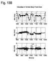
- FIGS. 13A-13C are time histories showing the experimental result data concerning velocities in vehicle body fixed axes
- FIG. 13A shows velocity components in the vehicle body fixed axes estimated by the embodiment of the integrated INS/GPS navigation system
- FIG. 13B shows velocity components in the vehicle body fixed axes estimated by the conventional technology
- FIG. 13C shows the difference between the data of FIG. 13A and the data of FIG. 13B .
- FIGS. 14A-14C are time histories showing the experimental result data concerning the vehicle pitch angle where FIG. 14A shows the vehicle pitch angle estimated by the embodiment of the integrated INS/GPS navigation system, FIG. 14B shows the vehicle pitch angle estimated by the conventional technology, and FIG. 14C shows the difference between the data of FIG. 14A and the data of FIG. 14B .
- FIG. 15A is a graph showing the experimental results involving the three-dimensional parking garage in accordance with the embodiment of the integrated INS/GPS navigation system and FIG. 15B is a graph showing the experimental results involving the three-dimensional parking garage in accordance with the conventional technology, where FIG. 15A shows a magnified view of FIG. 1B around the vehicle's backing motion in the top floor of the garage, and FIG. 15B shows a magnified view of FIG. 12B around the vehicle's backing motion in the top floor of the garage.
- FIG. 16 is a graph showing the theoretical positioning error in a straight drive due to pitch angle estimation errors.
- FIG. 17A is a graph showing the theoretical positioning error in cornering due to cyclic errors in velocity estimation
- FIG. 17B is a graph showing the simulated velocity error used for estimating the theoretical positioning error of FIG. 17A .
- FIGS. 18A and 18B are charts showing the time history of the parameters related to the embodiment of the integrated INS/GPS navigation system where FIG. 18A shows the time history of estimated sensor position with respect to the vehicle's rear wheel axis and FIG. 18B shows the time history of the sigma value of the estimate in FIG. 18A .
- FIG. 19 shows a display image with the vehicle contour and navigation system's position with proper geometry between the navigation system's position and the vehicle contour in which the distance between the navigation system and the rear wheel axis is automatically estimated by the navigation system.
- the navigation system's absolute position (latitude and longitude), the vehicle contour, and the map images of surrounding objects are aligned by placing the GPS antenna above the navigation system.
- FIG. 20 shows an example of message to a user or an installer indicating to place the GPS antenna above the navigation system.
- FIGS. 1A-1E show examples of structure related to the embodiments of the integrated INS/GPS navigation system and method.
- FIG. 1A is a block diagram showing an example of comprehensive system architecture of the embodiment of the integrated INS/GPS navigation system with the input-output relationship
- FIG. 1B is a schematic diagram showing an example of structure of an IMU (inertial measurement unit) with low-cost MEMS sensors
- FIG. 1C is a schematic diagram showing an example of structure of an auxiliary measurement unit
- FIG. 1D is a schematic diagram showing an example of structure of a GPS measurement unit
- FIG. 1E is a block diagram showing an example of structure of a navigation operation unit.
- the integrated INS/GPS navigation system includes an IMU (inertial measurement unit) 10 containing MEMS inertial sensors of a three-axis accelerometer and three-axis gyro, an inertial navigation system (INS) computational unit 20 , an iterated extended Kalman filter (IEKF) unit 30 , a calibration unit (Cal) 40 having an auxiliary measurement unit (Aux) 50 and a global positioning system (GPS) unit 60 , a navigation operation unit 70 , and a display 80 .
- IMU inertial measurement unit
- INS inertial navigation system
- IEEE extended Kalman filter
- the IMU 10 and the Cal 40 are configured to input various parameters
- the INS 20 , the IEKF 30 and the navigation operation unit 70 are configured to process the input parameters to produce state estimates of the vehicle including position estimates
- the display 80 is configured to output the resultant position estimates, etc.
- the IMU 10 measures vehicle's accelerations and angular rates.
- the IMU 10 includes a processor 12 , and the inertial sensors consisting of three (three-axis) accelerometers Acc x-z and three (three-axis) gyroscopes Gyro x-z.
- the accelerometers Acc x-z detect accelerations in the three (X,Y,Z) coordinates with respect to the sensor fixed coordinate system described in FIG. 3
- the gyroscopes Gyro x-z detect angular rates about the three (X,Y,Z) coordinates with respect to the sensor fixed coordinate system described in FIG. 3 .
- the inertial sensors are established by low-cost MEMS (micro-electro mechanical system) sensors.
- the processor 12 calculates the accelerations and angular rates of the vehicle based on the measured signals from the inertial sensors Acc x-z and Gyro x-z.
- the IMU 10 produces the measured data at a rate of, for example, 25 times per second (25 Hz), which is supplied to the INS 20 .
- the INS 20 is, for example, so called a Six Degrees of Freedom (6DOF) INS which executes the INS computation to update navigation state estimates (position, velocity, orientation, and sensor bias) and their covariances, i.e., uncertainties of estimates, upon the sensor measurement.
- the INS 20 updates the navigation state estimates at a rate of, for example, 25 times per second (25 Hz).
- the navigation state estimates are periodically calibrated by a Kalman filter, for example, Iterated Extended Kalman Filter (IEKF) 30 shown in FIG. 1A .
- KEF Iterated Extended Kalman Filter
- the Aux (auxiliary measurement unit) 50 is unique to the embodiments of the integrated INS/GPS navigation system and method.
- the Aux 50 is configured by a processor as shown in FIG. 1C to conduct an operation prescribed by a program. More specifically, the Aux 50 produces the auxiliary measurement data (reference data) involving a distance (d) between the navigation system (ex. inertial sensors of IMU) and a vehicle's rear wheel axis.
- the auxiliary measurement data (reference data) will be described in more detail later with respect to the vehicle side velocity in the description of analytical conditions.
- the Aux 50 sends the auxiliary measurement data to the Kalman filter 30 at a rate of, for example, 5 times per second (5 Hz).
- the GPS 60 is configured by a GPS antenna, a GPS receiver 60 , and a processor 62 .
- the GPS receiver 61 receives GPS signals from a plurality of artificial satellites
- the processor 62 calculates the estimated location of the vehicle by comparing clock signals and position data included in the GPS signals. More specifically, the GPS 60 measures the GPS antenna position and velocity based on range and range-rate information between the GPS antenna and multiple satellites in the field of view to send the measurements to the Kalman filter 30 .
- the GPS 60 produces the position and velocity data every one second (1 Hz).
- the state estimates from the INS 20 , the measurement data from the GPS 60 , and the auxiliary measurement data from the Aux 50 are combined by the Kalman filter 30 which optimally estimates, in real time, the states of the navigation system based on such noisy measurement data.
- the navigation state estimates from the INS 20 are periodically calibrated by the Kalman filter 30 by taking the differences between the INS state estimates and the calibration measurements (auxiliary measurement and GPS measurement) obtained from the Aux 50 and the GPS 60 , respectively.
- the auxiliary measurement from the Aux 50 involves the analytical condition which is the relationship between the vehicle's lateral directional (side) velocity, the distance of the sensor position with respect to the rear wheel axis, and the angular rate with respect to the vehicle's z-axis.
- the integrated INS/GPS navigation system of FIG. 1A estimates the following parameters: three position parameters (latitude, longitude, and altitude), three velocity parameters (velocities along the sensor fixed x, y, and z-axes), three orientation parameters (roll, pitch, and yaw angles of the sensor fixed coordinate system with respect to the North-East-Down coordinate system), six sensor biases (accelerometers and gyro biases along the sensor fixed x, y, and z-axes, respectively), two sensor attachment angles (pitch and yaw angles with respect to the vehicle body fixed coordinate system), and the position of the sensor IMU with respect to the vehicle's rear wheel axis.
- three position parameters latitude, longitude, and altitude
- three velocity parameters velocity along the sensor fixed x, y, and z-axes
- three orientation parameters roll, pitch, and yaw angles of the sensor fixed coordinate system with respect to the North-East-Down coordinate system
- six sensor biases accelerelerometers
- the position information including latitude, longitude, altitude, and the position of the sensor IMU with respect to the rear wheel axis will be used to display the vehicle contour and the navigation system with proper geometry between the navigation system's position and the vehicle contour on the display 80 in which the distance between the navigation system and the rear wheel axis is automatically estimated by the navigation system.
- the navigation system's absolute position (latitude, longitude, (and altitude if necessary)) and position information from a map database are aligned by placing the GPS antenna above the navigation system.
- the navigation operation unit 70 is provided to conduct an overall operation of the navigation system for specifying a destination, searching and calculating an optimum route to the destination, conducting the route guidance operation to the destination, displaying a vehicle contour image with respect to images of surrounding objects, etc.
- the navigation operation unit 70 includes an input device 71 for selecting a menu, specifying a destination, executing a command, etc., a processor 72 for controlling an overall operation of the navigation system, and a display controller 73 for controlling the operation of the display 80 .
- the input device 71 can be various hard keys, a touch screen formed on the display 80 , a remote controller, a voice interface, etc.
- the navigation operation unit 70 further includes a map database (data storage device) 74 such as a hard disc, CD-ROM, DVD, flash memory, etc., for storing the map data (position data of links, nodes, polygons, etc.), a ROM 75 for storing various programs for navigation operations, and a RAM 76 for storing operational data or a processing result such as a guidance route.
- the map data is used to calculate a route to the destination, to produce a map image on the navigation screen such as on the display 80 , and to provide various information on points of interest (POI), etc.
- An example of programs stored in ROM 75 includes a route search program to search and calculate possible routes to the destination, and a map matching program for matching the position estimates from the INS 20 with link, node and polygon data from the map database.
- the navigation operation unit 70 further includes a sensor unit 77 for detecting distances form other vehicles, pedestrians, structures, etc., a wireless communication device 78 for wireless communication with a remote server such as a traffic information server, a local event server, an internet server, a social network server, etc., and a contour database 79 for storing information on the vehicle contour.
- the sensor unit 77 may be configured by a plurality of radar sensors, cameras, etc. to measure shapes and distances from the outer objects.
- the vehicle contour data for the contour database 79 may be available from vehicle manufacturers or from data books in the industry. The vehicle contour data is used for showing images on the display 80 so that the user can easily comprehend the relationship among the vehicle contour, a location of the navigation system in the vehicle, and the objects surrounding the vehicle.
- FIG. 2 is a flowchart showing an example of process in the integrated INS/GPS navigation system and method involving the preferred embodiment of FIGS. 1A-1E .
- the IMU sensor measures vehicle three-axis accelerations and three-axis angular rates.
- This step is conducted by the IMU 10 having the accelerometers x-z and gyroscopes x-z shown in FIGS. 1A and 1B . As noted above, this step is conducted at a relatively high frequency, e.g., 25 Hz.
- the measured accelerations and angular rates are sent to the INS (inertial navigation system) in step 112 to update the navigation state estimates (position, velocity, orientation, and sensor bias) and their covariances.
- INS inertial navigation system
- An example of INS is a “Six Degrees of Freedom (6DOF) INS’ as indicated by the INS 20 in FIG. 1A .
- this step is conducted at relatively high frequency, for example, 25 Hz.
- the parameters from the INS are periodically calibrated at lower frequencies in step 114 according to the IEKF (iterated extended Kalman filter) technology by incorporating the auxiliary measurement data (reference data) from the Auxiliary measurement unit.
- this process is conducted by the Kalman filter 30 which receives the state estimates from the INS 20 and the auxiliary measurement data from the Aux 50 .
- the process incorporates the GPS measurements.
- the GPS (GPS Measurement Unit) 60 receives GPS signals from a plurality of artificial satellites and calculates the estimated position and velocity of the vehicle by comparing clock signals and position data included in the GPS signals. Typically, the GPS 60 produces the position and velocity data every one second (1 Hz), which is sent to the Kalman filter 30 as shown in FIG. 1A .
- step 116 the navigation state estimates (position, velocity, orientation, and sensor bias) from the INS 20 are calibrated by the Kalman filter 30 by taking the differences between the INS state estimates and the GPS measurements obtained from the GPS 60 .
- the process repeats the above steps 111 - 116 as an integrated INS/GPS navigation system to continuously optimize the navigation position estimates.
- the GPS signals may not be available for a long period of time if a vehicle is in a tunnel, building, or valley of high-rise buildings, thus in such a case, the calibration data based on the GPS measurement cannot be used by the Kalman filter 30 . Even in such a situation, the integrated INS/GPS navigation system and method disclosed here is able to maintain the high positioning accuracy since it utilizes the auxiliary measurement data from the Aux 50 to minimize the position error associated with the vehicle side velocity.
- step 118 the process combines the optimized position estimates obtained in the foregoing steps with the position information retrieved from the map database and the vehicle contour data. This process is conducted to match the optimized position estimates of the navigation system in the vehicle with the objects surrounding the vehicle and the vehicle contour. In the example of FIGS. 1A and 1E , this step is conducted by the navigation operation unit 70 which includes the map database 74 and the contour database 79 .
- the navigation system displays the vehicle contour and the position of the navigation system in the vehicle with proper geometry between the navigation system's position and the vehicle contour.
- the distance between the navigation system and the rear wheel axis is automatically estimated by the navigation system.
- the navigation system's absolute position (latitude, longitude, (and altitude if necessary)) and the surrounding objects produced from the map database are aligned by placing the GPS antenna above the navigation system.
- FIG. 3 defines the sensor fixed coordinate system in which each of x, y, and z-axis represents a sensor's sensitive direction.
- a parameter with respect to the sensor coordinate system is indicated by a subscript of “s”.
- FIG. 4 defines the vehicle body fixed coordinate system with a top view and a bird view in which the x-axis is defined toward the vehicle's forward direction, the y-axis is defined toward the vehicle's right-hand direction, and the z-axis is defined in the vehicle's downward direction from the ceiling to floor.
- a parameter with respect to the vehicle body fixed coordinate system is indicated by a subscript of “b”.
- the direction of the z b -axis in the top view is represented by “the forward rotation of a right screw”, which is a common notation in physics.
- the clockwise rotation represents that we see the rear view of an arrow; the counter-clockwise rotation represents that we see the front view of an arrow.
- FIG. 5 defines the North-East-Down (NED) coordinate system in which the x-axis is defined in the northerly direction, the y-axis is defined in the easterly direction, and the z-axis is defined in the vertically downward direction.
- NED North-East-Down
- the analytical condition incorporated in the embodiments of the integrated INS/GPS navigation system and method is described in detail.
- the analytical condition is derived from the internal geometry of the sensor position with respect to the rear wheel axis. This section corresponds to the function of the Aux (Auxiliary measurement unit) 50 in the block diagram of FIG. 1A and the step 113 in the flowchart of FIG. 2 .
- FIG. 6 shows so-called Ackermann Steering Geometry (see Genta, G., “MOTOR VEHICLE DYNAMICS Modeling and Simulation”, World Scientific Publishing Co. Pte. Ltd., 1997, 5 Toh Tuck Link, Singapore, pp. 206-207) in which a tangential line from the center of each front wheel passes a single center of cornering.
- FIG. 6 also shows that the rear wheels do not tilt in cornering for majority of vehicles.
- FIG. 7 illustrates that the navigation system attached to the vehicle has the velocity vector “V” in the direction tangential to the line toward the center of cornering which is not exactly aligned in the x b direction.
- the existence of the side velocity, or the y b component of V, or v by is largely noticeable for a driver of a van or pickup which has a long body from the front to end.
- ⁇ bz vehicle's directional angular rate with respect to the z b -axis
- V magnitude of V
- INS inertial navigation system
- a dot above a variable e.g., if ⁇ dot over (v) ⁇ s , represents the time-rate of the variable v s .
- ⁇ dot over (v) ⁇ s ⁇ s ⁇ v s +a s +g 5
- Velocity Rate Equation in which
- v s [ v sx v sy v sz ] ⁇ : ⁇ ⁇ velocity ⁇ ⁇ vector ⁇ ⁇ with ⁇ ⁇ respect ⁇ ⁇ to ⁇ ⁇ the ⁇ ⁇ sensor ⁇ - ⁇ fixed coorinated ⁇ ⁇ system
- ⁇ s [ ⁇ sx ⁇ sy ⁇ sz ] ⁇ : ⁇ ⁇ three ⁇ - ⁇ axis ⁇ ⁇ gyro ⁇ ⁇ output ⁇ ⁇ vector ⁇ ⁇ with ⁇ ⁇ respect ⁇ ⁇ to ⁇ ⁇ the sensor ⁇ - ⁇ fixed ⁇ ⁇ coordinate ⁇ ⁇ system
- Equation (2) is derived in the conventional INS (Inertial Navigation System) technology as shown below:
- the transformation matrix, T ns carries the information of angles between the sensor fixed coordinate system and the NED coordinate system.
- T ns The transformation matrix
- the transformation matrix, T hs carries the information of angles between the sensor fixed coordinate system and the vehicle body fixed coordinate system.
- T hs The transformation matrix
- Equation (5) To time-integrate Equation (5) on a processor, the following well-known Runge-Kutta 4th order equation is used (see Kreyszig, E., “Advanced Engineering Mathematics”, John Wiley & Sons, 1999, New York, N.Y., pp. 947-948):
- the Kalman filter technology is described which is used to calibrate the INS estimates based upon reference measurement. This section corresponds to the functions of the Kalman filter 30 in the block diagram of FIG. 1A and the step 114 in the flowchart of FIG. 2 .
- the first step of Kalman filter implementation is to linearize Equation (5) around a set of particular estimates of ⁇ circumflex over (x) ⁇ k to approximate the dynamics of the small error ⁇ x with respect to the currently known estimates, ⁇ circumflex over (x) ⁇ k .
- a parameter with a hat represents that it is an estimate of the parameter, e.g., ⁇ circumflex over (x) ⁇ k is the estimated amount of the parameter, x k . Since the linearized equation remains accurate only for small value of ⁇ x around ⁇ circumflex over (x) ⁇ k , it is called “small perturbation equation”.
- x k ⁇ circumflex over (x) ⁇ k + ⁇ x: relationship between the estimated value, ⁇ circumflex over (x) ⁇ k , and the exact value, x k
- w k [ w ⁇ ⁇ ⁇ x w ⁇ ⁇ ⁇ y w ⁇ ⁇ ⁇ z w ax w ay w az ] ⁇ : ⁇ ⁇ input ⁇ ⁇ noise ⁇ ⁇ vector ⁇ ⁇ regarding ⁇ ⁇ three ⁇ - ⁇ axis ⁇ ⁇ gyro output , ⁇ s , and ⁇ ⁇ three ⁇ - ⁇ axis ⁇ ⁇ accelerometer ⁇ ⁇ output , ⁇ ⁇ a s , ⁇ with ⁇ ⁇ white ⁇ ⁇ model ⁇ ⁇ in ⁇ ⁇ the ⁇ ⁇ discrete ⁇ ⁇ time ⁇ ⁇ space Standard deviation ( ⁇ ) of each white noise is defined as follows:
- ⁇ , ⁇ , ⁇ are small perturbations of “c 00 , c 10 , c 20 , c 21 ” where “ ⁇ , ⁇ , ⁇ ” and “ ⁇ c 00 , ⁇ c 10 , ⁇ c 20 , ⁇ C 21 ” have the following relationship:
- g n [ 0 0 9.8 ⁇ ⁇ m ⁇ / ⁇ s 2 ] ⁇ : ⁇ ⁇ gravity ⁇ ⁇ vector ⁇ ⁇ with ⁇ ⁇ respect ⁇ ⁇ to ⁇ ⁇ the ⁇ ⁇ NED coordinate ⁇ ⁇ system
- Equation (6) updates navigation states at a high frequency
- uncertainties of the navigation estimates accumulate over time.
- the uncertainties of the navigation states can be mathematically represented by a covariance matrix as follows:
- the second step of Kalman filter implementation is to find the relationship between available reference measurements and the Kalman filter states. Such a relationship is called measurement equation.
- a measurement equation is derived for each measurement in the following.
- the non-linear equation is linearized in terms of a set of particular estimates of ⁇ circumflex over (x) ⁇ k .
- This subsection corresponds to the functions of the GPS 60 in the block diagram of FIG. 1A and the step 115 in the flowchart of FIG. 2 .
- the size of each measurement error is described in the following: ⁇ nby ⁇ square root over ( ⁇ circumflex over (d) ⁇ 2 ⁇ circumflex over (p) ⁇ 20 2 N ⁇ x 2 + ⁇ circumflex over (d) ⁇ 2 ⁇ circumflex over (p) ⁇ 22 2 N ⁇ z 2 ) ⁇ : standard deviation for n by derived from Equation (13-2);
- a constant parameter of ⁇ nby 0.05 (m/s) is also a good candidate.
- R k [ ⁇ N 2 0 0 0 0 0 0 0 ⁇ E 2 0 0 0 0 0 ⁇ D 2 0 0 0 0 0 0 0 ⁇ vnx 2 0 0 0 0 0 0 0 ⁇ vny 2 0 0 0 0 0 ⁇ vnz 2 ] ⁇ : ⁇ ⁇ for ⁇ ⁇ GPS ⁇ ⁇ Measurement
- ⁇ s [ ⁇ sx ⁇ sy ⁇ sz ] ⁇ : ⁇ ⁇ three ⁇ - ⁇ axis ⁇ ⁇ gyro ⁇ ⁇ output ⁇ ⁇ vector ⁇ ⁇ with ⁇ ⁇ respect ⁇ ⁇ to ⁇ ⁇ the sensor ⁇ - ⁇ fixed ⁇ ⁇ coordinate ⁇ ⁇ system
- a s [ a sx a sy a sz ] ⁇ : ⁇ ⁇ three ⁇ - ⁇ axis ⁇ ⁇ accelerometer ⁇ ⁇ output ⁇ ⁇ vector ⁇ ⁇ with ⁇ ⁇ respect to ⁇ ⁇ the ⁇ ⁇ sensor ⁇ - ⁇ fixed ⁇ ⁇ coordinate Simulation Results
- FIG. 11A through FIG. 18B show simulation results of the embodiments of the INS/GPS navigation system and method described above using the sensor data collected along an actual on-road drive.
- a mid-sized van was used for this test drive, and the distance of the sensor position with respect to the rear wheel axis is known to be about 1.7 m. Therefore, the actual v by component (side velocity) is definitely non-zero.
- FIG. 11A shows the top view of the navigation solutions with the embodiments applied to the sensor data in which a vehicle drives through a spiral passage of a three-dimensional parking garage building in Yokohama, Japan.
- the drive inside the parking garage lasts about 4 minutes in which there is no GPS signal available.
- the spiral trajectory makes circles in FIG. 11A which are desirably located approximately in the same place.
- FIG. 11B shows the same navigation solutions in the bird view to visualize the vehicle's three-dimensional motion. Although FIG. 11B shows the almost successful result, there is a discrepancy between the entrance height and the exit height for about 10 m which represents navigation inaccuracy.
- FIG. 13A shows the estimated velocity components in the vehicle body fixed axes made by the embodiments of the new navigation system and method
- FIG. 13C shows the difference of v bx (vehicle's forward velocity) in FIG. 13B from the data in FIG. 13A which ensures the smaller velocity estimates in FIG. 13B than FIG. 13A .
- FIG. 14A shows the vehicle's pitch-angle estimate, i.e., E 2 (sensor pitch angle to the NED surface) ⁇ A 2 (sensor attachment pitch angle to vehicle) made by the embodiments of the new navigation system and method.
- FIG. 14C shows the difference of the data in FIG. 14B from the data in FIG. 14A . It is clear that the conventional technology makes larger estimates of pitch angle up to two degrees over the new navigation system and method.
- FIG. 15A shows a magnified view of the navigation trajectory made by the embodiments (the same as FIGS. 11A and 11B ) around the vehicle's proper backing motion in the top floor of the spiral parking garage.
- the excessive backing motion in FIG. 15B made by the conventional technology is the primary source of large positioning error.
- 2-degree error in pitch-angle estimation results in 17 m of transitional positioning error after 10 seconds in a forward or backward straight drive as calculated in the following:
- FIG. 16 shows the theoretical amount of the positioning error in a straight path due to pitch angle-estimation error of 2 degrees over time based on the equation above.
- FIG. 17A shows a plotting of the theoretical positioning error in cornering due to cyclic velocity-estimation error.
- the plotting with dots represents the exact path emulating the circular motion in FIG. 11A with the cornering radius (R) of 10 m and cornering angular rate ( ⁇ ) of 45 deg/sec.
- FIG. 17B shows the velocity profiles used to create FIG. 17A in which the plotting with dots (top line) represents the true velocity used to make the circular path and the plotting with “x” (two broken lines) represents the velocity with cyclic error used to create the moving oval trajectory. Aggregation of the errors of FIGS. 16 and 17A appears in FIGS. 12A and 12B .
- FIG. 18A shows the time history of the estimated distance between the position of the sensor IMU and the vehicle's rear-wheel axis made by the Kalman filter process.
- FIG. 18B shows the associated uncertainty (sigma value) obtained from the covariance matrix in the Kalman filtering process according to the following equation.
- ⁇ of d ⁇ square root over ( P [18,18]) ⁇ ( m ) in which P is the covariance matrix.
- the integrated INS/GPS navigation system and method provides a unique display method utilizing the internal geometry of the sensor position with respect to the vehicle's rear wheel axis.
- the embodiments of the integrated INS/GPS navigation system and method will produce the position estimates including the internal geometry of the sensor IMU position with respect to the vehicle's rear wheel axis with high accuracy.
- Such position estimates will be aligned with vehicle contour information and position information of links, nodes, polygons, etc., i.e., objects (map image) surrounding the vehicle, derived from the map database.
- This section corresponds to the functions of the navigation operation unit 70 and the display 80 in the block diagram of FIG. 1A and the steps 118 and 119 in the flowchart of FIG. 2 .
- such a matching process can be conducted by the navigation operation unit 70 with use of the information from the map database 74 and the contour database 79 .
- FIG. 19 shows a display image with the vehicle contour and navigation system's position with proper geometry between the vehicle contour and navigation system's position in which the distance between the navigation system and the rear wheel axis is automatically estimated by the method of present invention. Showing the vehicle contour with proper geometry with respect to the navigation system as well as to the objects surrounding the vehicle visually aids a driver's safety consciousness.
- the navigation system's absolute position (latitude and longitude) and map database are aligned by placing the GPS antenna above the navigation system.
- FIG. 20 shows an instruction to a user or an installer indicating to place the GPS antenna above the navigation system.
- the embodiments of the integrated INS/GPS navigation system and method achieve the following advantageous effects: (1) regardless of the sensor position, the distance of the sensor position with respect to the rear wheel axis will be automatically estimated without need of measuring the distance by hand, which will be utilized to enhance navigation accuracy; (2) high positioning accuracy is maintained even when GPS signals are lost for a long period of time using a low-cost MEMS IMU; (3) the best sensor position to achieve the highest navigation accuracy is the center of the rear-wheel axis which is practically available by placing the sensor IMU at the bottom-center of the trunk of the vehicle; (4) the driver's safety consciousness is enhanced by the visual aid from the display showing the vehicle contour with proper geometry with respect to the navigation system as well as to the surrounding objects.
Abstract
Description
| 1. incorporate the constant parameter “d” into the INS navigation states and the Kalman |
| filter's | METHOD | 1 |
| 2. use the following auxiliary measurement in the Kalman filter's calibration process in |
| addition to |
| 0 = vby − dωbz | METHOD 2 | |
These methods will be further described in the following sections.
0=v by (A)′
This special condition is within the scope of the analytical condition of Equation (A) which can be achieved by d=0.
INS Technology
{dot over (v)} s=ωs ×v s +a s +g 5 (1) Velocity Rate Equation
in which
gs: gravity vector transformed into the sensor-fixed coordinate system
{dot over (c)}00 =c 01ωsz −c 02ωsy
{dot over (c)}10 =c 11ωsz −c 12ωsy
{dot over (c)}20 =c 21ωsz −c 22ωsy
{dot over (c)}21 =−c 20ωsz +c 22ωsx (2) Orientation Rate Equation
in which
Equation (2) is derived in the conventional INS (Inertial Navigation System) technology as shown below:
in which
E3: yaw angle of the sensor coordinate system with respect to the NED coordinate system
E2: pitch angle of the sensor coordinate system with respect to the NED coordinate system
E1: roll angle of the sensor coordinate system with respect to the NED coordinate system
CE1, SE1 . . . : cos(E1), sin(E1), and so on
In the above steps, the following automotive platform conditions are assumed:
-
- −90 deg<E2<+90 deg −90 deg<E1<+90 deg
{dot over (N)}=vnx
{dot over (E)}=vny
{dot over (D)}=vnz (3) Position Rate Equation
in which
N; northerly displacement
E: easterly displacement
D: downward displacement
- −90 deg<E2<+90 deg −90 deg<E1<+90 deg
The following equations represent constant dynamics. Sensor biases are assumed constant as follows, although they drift slowly according to the temperature change in reality.
{dot over (b)}ωx=0
{dot over (b)}ωy=0
{dot over (b)}ωz=0 (4-1)
{dot over (b)}ax=0
{dot over (b)}ay=0
{dot over (b)}az=0 (4-2)
{dot over (p)}00=0
{dot over (p)}10=0
{dot over (p)}20=0 (4-3)
{dot over (d)}=0 (4-4)
in which
d: distance between the sensor IMU position and the rear wheel axis
in which
A3: yaw angle of the sensor coordinate system with respect to the vehicle body fixed coordinate system
A2: pitch angle of the sensor coordinate system with respect to the vehicle body fixed coordinate system
A1: roll angle of the sensor coordinate system with respect to the vehicle body fixed coordinate system
CA2, SA2, . . . : cos(A2), sin(A2), and so on
In the above steps, the following practical conditions are assumed:
A 1=0 −90 deg<A2<+90 deg −90 deg<A3<+90 deg
{dot over (x)}=f(x,ω s ,a s) (5)
in which the non-linear state vector is defined by
x=[v sx ,v sy ,v sz ,N,E,D,c 00 ,c 10 ,c 20 ,c 21 ,b ωx ,b ωy ,b ωz ,b ax ,b ay ,b ax ,p 00 ,p 10 ,p 20 ,d]
where incorporation of “d” into the navigation states is one of the unique methods of the navigation system as mentioned earlier as
in which
T: sampling time, e.g., 0.04 sec for 25 Hz
xk value of x at the k-th time epoch of t=tk=T×k
The INS technology described above is MEMS based simplified INS method based on conventional INS technology with simplification of small terms such as Earth rotation and Earth curvature (see U.S. Pat. No. 7,957,898 “Computational Scheme for MEMS Inertial Navigation Systems” issued to Hoshizaki, T.).
Kalman Filter Technology
δx k+1 =F({circumflex over (x)} k)δx kΓk({circumflex over (x)} k w k (7)
in which the Kalman filter's state vector (small perturbation vector) is given by
δx=[δv sx ,δv sy ,δv sz ,δN,δE,δD,δα,δβ,δγ,b ωx ,b ωy ,b ωz ,b ax b ay b az ,δb,δc,δd]
where incorporation of “d” into the Kalman filter states is one of the unique methods of this navigation system as mentioned earlier as
{circumflex over (x)}k: estimated value of Xk at t=tk
xk={circumflex over (x)}k+δx: relationship between the estimated value, {circumflex over (x)}k, and the exact value, xk
Standard deviation (σ) of each white noise is defined as follows:
Similarly, “δb, δc” are small perturbations of “p00, p10, p20,” where “δb, δc” and “δp00, δp10, δp20” have the following relationship:
Here, it is assumed that there is no roll angle of the sensor-fixed coordinate system with respect to the vehicle-fixed coordinate system (A1=0), so as its small perturbation δa=0).
T: sampling time, e.g., T=0.04 sec for 25 Hz
| (10) |
| F({circumflex over (x)}k) |
| δvsx | δvsy | δvsz | δN | δE | δD | δα | δβ | δγ | bωx | bωy | bωz | bax | bay | baz | δb | δc | δd |
| δvsx | I-Rot(ωs)T | −{circumflex over (T)}snRot(gn)T | Rot({circumflex over (v)}s)T | IT | ||||||
| δvsy | ||||||||||
| δvsz |
| δN | {circumflex over (T)}nsT | I | Rot({circumflex over (v)}n)T | |||||||||
| δE | ||||||||||||
| δD |
| δα | I | -{circumflex over (T)}nsT | ||||||||||||
| δβ | ||||||||||||||
| δγ |
| bωx | I | |||||||||||||||
| bωy | ||||||||||||||||
| bωz |
| bax | I | |||||||||||||||
| bay | ||||||||||||||||
| baz |
| δb | I | |||||||||||||||
| δc | ||||||||||||||||
| δd | ||||||||||||||||
| Γ({circumflex over (x)}k) |
| (11) |
| wωx, wωy, wωz | wax, way, waz | ||
| δvxb | Rot({circumflex over (v)}s) | I | ||
| δvyb | ||||
| δvzb | ||||
| δN | ||||
| δE | ||||
| δD | ||||
| δα | −{circumflex over (T)}ns | |||
| δβ | ||||
| δγ | ||||
| bωxb | ||||
| bωyb | ||||
| bωzb | ||||
| baxb | ||||
| bayb | ||||
| bazb | ||||
| δb | ||||
| δc | ||||
| δd | ||||
The covariance matrix must be also updated along with Equation (6) at a high frequency according to the following equation so that the Kalman filter method can calibrate the navigation state estimates:
P k+1 − F({circumflex over (x)} k)P k − F({circumflex over (x)} k)T+Γ({circumflex over (x)} k)Q kΓ({circumflex over (x)} k)T (12)
in which
superscript “T”: transpose of the matrix
superscript “−”: before the Kalmanf filter calibration at the time-epoch of tk
superscript “+”: after the Kalmanf filter calibration at the time-epoch of tk
covariance matrix of wk
Kalman Filter Measurement Equation:
V by dω bz
To incorporate this condition into the Kalman filter algorithm, an auxiliary measurement of z1 is incorporated as
z 1 =v by −dω bz whose reference value is always z 1=0 (13-1)
where incorporation of auxiliary measurement equation (13-1) into the Kalman filter measurement is one of the unique methods of this navigation system as mentioned earlier as
Similarly, since a vehicle is predominantly attached to the road surface, it is also true that:
v bz=0
To incorporate this condition into the Kalman filter algorithm, an auxiliary measurement of z2 is incorporated as
z2 =v bz whose reference value is always z 2=0 (14-1)
This is the 3rd row of the following vector equation in terms of the navigation states:
z=T bs v x
This is a non-linear measurement equation. To incorporate this into the Kalman filter algorithm, the non-linear equation is linearized in terms of a set of particular estimates of {circumflex over (x)}k. After a short derivation, the linear perturbation equation is found as the 3rd row of:
δz=Rot({circumflex over (v)} b)Δ+{circumflex over (T)}bs δv s
or,
δz 2 =[{circumflex over (p)} 200{circumflex over (p)} 22 ]δv s +[−{circumflex over (v)} by {circumflex over (v)} bx0]Δ (14-2)
z p =p n (15-1)
δz p =δp n (15-2)
in which
Therefore, the measurement equation will be
z v =v n =T ns v s (16-1)
This is a non-linear measurement equation. To incorporate this into the Kalman filter algorithm, the non-linear equation is linearlized in terms of a set of particular estimates of {circumflex over (x)}k to obtain the following equation.
δz v =Rot({circumflex over (v)} n)ε+{circumflex over (T)}ns δv x (16-2)
z k =h k(x k) (17)
in which
Summarizing Equations of (13-2), (14-2), (15-2), and (16-2) reduces to a vector representation of:
δz k =H({circumflex over (x)} k)δx k +n k (17-2)
in which
nk is a measurement error vector which is assumed to be white noise. The size of each measurement error is described in the following:
σnby√{square root over ({circumflex over (d)}2{circumflex over (p)}20 2Nωx 2+{circumflex over (d)}2{circumflex over (p)}22 2Nωz 2)}: standard deviation for nby derived from Equation (13-2);
- (i) H1 is always available no matter if GPS signals are available or not. IEKF calibration is always executed based on H1 at an intermediate frequency, e.g., 5 Hz.
- (ii) IEKF calibration based on GPS measurement is executed at 1 Hz using H2 only when GPS signals are available.
| (18) | |
| H({circumflex over (x)}k) | |
| δvxb | δvyb | δvzb | δN | δE | δD | δα | δβ | δγ | bωx | bωy | bωz | bax | bay | baz | δb | δc | δd | ||
| H1 | δzvby | {circumflex over (p)}10 | {circumflex over (p)}11 | {circumflex over (p)}11 | {circumflex over (d)}{circumflex over (p)}20 | 0 | {circumflex over (d)}{circumflex over (p)}22 | -{circumflex over (d)}{circumflex over (ω)}bx | -{circumflex over (V)}bx | _{circumflex over (ω)}bz | |||||||||
| δvvbz | {circumflex over (p)}20 | 0 | {circumflex over (p)}22 | {circumflex over (V)}bx | 0 | ||||||||||||||
| H2 | δzp | 1 | |||||||||||||||||
| 1 | |||||||||||||||||||
| 1 | |||||||||||||||||||
| δzv | ĉ00 | ĉ01 | ĉ02 | 0 | -{circumflex over (V)}nz | -{circumflex over (V)}ny | |||||||||||||
| ĉ10 | ĉ11 | ĉ12 | -{circumflex over (V)}nz | 0 | -{circumflex over (V)}nx | ||||||||||||||
| ĉ20 | ĉ21 | ĉ22 | -{circumflex over (V)}ny | -{circumflex over (V)}nx | 0 | ||||||||||||||
k k,i =P k − H k T({circumflex over (x)} k,i +)(H k({circumflex over (x)} k,i +)P k − H k T({circumflex over (x)} k,i +)+R k)−1 (19) Computation of Kalman Gain, K
{circumflex over (x)} k,i+1 + ={circumflex over (x)} k − +K k,i [z k −h k({circumflex over (x)} k,i +)−H k({circumflex over (x)} k,i +)({circumflex over (x)} k − −{circumflex over (x)} k,i +)] (20) Calibration of State Estimates, x
P k,i+1 +=(I−K k,i H k({circumflex over (x)} k,i +))P k − (21) Calibration of Covariance, P
in which
- {circumflex over (x)}k,0 +={circumflex over (x)}k − sign in the superscript represents that the parameter is calibrated, the “−” sign in the superscript represents that the parameter is not calibrated yet
- Rk: covariance matrix regarding measurements
Since the size of H({circumflex over (x)}k) dynamically changes, the associated Rk also changes according to the following:
ωsx +=ωsx − +b ωx
ωsy +=ωsy − +b ωy
ωsz +=ωsz − +b ωz
a sx + =a sx − +b ax
a sy + =a sy − +b ay
a sz + =a sz − +b az
in which
Simulation Results
σ of d=√{square root over (P[18,18])}(m)
in which P is the covariance matrix. These figures show that, the more cornering, the more calibrated the distance estimation. After undergoing the intensive cornering in a spiral parking garage, the estimation of the distance between the position of the sensor IMU and the vehicle's rear-wheel axis is well converged.
Display
Claims (16)
Priority Applications (1)
| Application Number | Priority Date | Filing Date | Title |
|---|---|---|---|
| US13/307,399 US9026263B2 (en) | 2011-11-30 | 2011-11-30 | Automotive navigation system and method to utilize internal geometry of sensor position with respect to rear wheel axis |
Applications Claiming Priority (1)
| Application Number | Priority Date | Filing Date | Title |
|---|---|---|---|
| US13/307,399 US9026263B2 (en) | 2011-11-30 | 2011-11-30 | Automotive navigation system and method to utilize internal geometry of sensor position with respect to rear wheel axis |
Publications (2)
| Publication Number | Publication Date |
|---|---|
| US20130138264A1 US20130138264A1 (en) | 2013-05-30 |
| US9026263B2 true US9026263B2 (en) | 2015-05-05 |
Family
ID=48467564
Family Applications (1)
| Application Number | Title | Priority Date | Filing Date |
|---|---|---|---|
| US13/307,399 Active 2032-04-20 US9026263B2 (en) | 2011-11-30 | 2011-11-30 | Automotive navigation system and method to utilize internal geometry of sensor position with respect to rear wheel axis |
Country Status (1)
| Country | Link |
|---|---|
| US (1) | US9026263B2 (en) |
Cited By (11)
| Publication number | Priority date | Publication date | Assignee | Title |
|---|---|---|---|---|
| US9638525B1 (en) * | 2016-01-04 | 2017-05-02 | Caterpillar Inc. | Systems and methods for monitoring positioning of a machine by utilizing a virtual IMU |
| WO2017214089A1 (en) | 2016-06-06 | 2017-12-14 | Regeneron Pharmaceuticals, Inc. | Non-human animals expressing antibodies with human lambda light chains |
| CN109443355A (en) * | 2018-12-25 | 2019-03-08 | 中北大学 | Vision based on adaptive Gauss PF-inertia close coupling Combinated navigation method |
| CN109443353A (en) * | 2018-12-25 | 2019-03-08 | 中北大学 | Vision based on fuzzy self-adaption ICKF-inertia close coupling Combinated navigation method |
| CN109724595A (en) * | 2017-10-31 | 2019-05-07 | 北京自动化控制设备研究所 | A kind of inertia visual position Combinated navigation method based on sequential detection |
| US10746551B2 (en) * | 2015-10-15 | 2020-08-18 | Mitsubishi Electric Corporation | Positioning apparatus and positioning method |
| US10907971B2 (en) | 2017-12-08 | 2021-02-02 | Regents Of The University Of Minnesota | Square root inverse Schmidt-Kalman filters for vision-aided inertial navigation and mapping |
| US11466990B2 (en) * | 2016-07-22 | 2022-10-11 | Regents Of The University Of Minnesota | Square-root multi-state constraint Kalman filter for vision-aided inertial navigation system |
| US11486707B2 (en) | 2008-03-28 | 2022-11-01 | Regents Of The University Of Minnesota | Vision-aided inertial navigation |
| US11719542B2 (en) | 2014-06-19 | 2023-08-08 | Regents Of The University Of Minnesota | Efficient vision-aided inertial navigation using a rolling-shutter camera |
| US11940277B2 (en) | 2018-05-29 | 2024-03-26 | Regents Of The University Of Minnesota | Vision-aided inertial navigation system for ground vehicle localization |
Families Citing this family (30)
| Publication number | Priority date | Publication date | Assignee | Title |
|---|---|---|---|---|
| EP2756331B1 (en) * | 2011-09-12 | 2023-04-05 | Continental Automotive Technologies GmbH | Time-corrected sensor system |
| US10260904B2 (en) * | 2013-03-19 | 2019-04-16 | Regents Of The University Of Minnesota | Position sensing system |
| CN103487820B (en) * | 2013-09-30 | 2016-03-16 | 东南大学 | A kind of vehicle-mounted strapdown/satellite tight integration seamless navigation method |
| CN103941274B (en) * | 2014-04-15 | 2017-01-18 | 北京北斗星通导航技术股份有限公司 | Navigation method and terminal |
| DE102014211176A1 (en) * | 2014-06-11 | 2015-12-17 | Continental Teves Ag & Co. Ohg | Method and system for correcting measurement data and / or navigation data of a sensor-based system |
| DE102014211175A1 (en) * | 2014-06-11 | 2015-12-17 | Continental Teves Ag & Co. Ohg | Method and system for initializing a sensor fusion system |
| CN104061899B (en) * | 2014-06-20 | 2016-03-30 | 东南大学 | A kind of vehicle side inclination angle based on Kalman filtering and angle of pitch method of estimation |
| CN104049269B (en) * | 2014-06-25 | 2016-08-24 | 哈尔滨工程大学 | A kind of target navigation mapping method based on laser ranging and MEMS/GPS integrated navigation system |
| CN104374389B (en) * | 2014-12-10 | 2017-04-05 | 济南大学 | A kind of IMU/WSN Combinated navigation methods towards indoor mobile robot |
| KR102623680B1 (en) * | 2015-02-10 | 2024-01-12 | 모빌아이 비젼 테크놀로지스 엘티디. | Sparse map for autonomous vehicle navigation |
| CN104748749B (en) * | 2015-03-11 | 2017-05-03 | 中国矿业大学 | Automatic inertial navigation deviation correction device and method of parallel type movable crushing system |
| US10564297B2 (en) * | 2015-08-20 | 2020-02-18 | Trimble Inc. | Cordless inertial vehicle navigation with elevation data input |
| EP3358302B1 (en) * | 2015-09-30 | 2021-03-31 | Nissan Motor Co., Ltd. | Travel control method and travel control device |
| CN105352528B (en) * | 2015-10-27 | 2018-05-18 | 湖北航天技术研究院总体设计所 | A kind of ins error online compensation method applied to ballistic missile |
| US10048686B2 (en) * | 2015-11-06 | 2018-08-14 | The Boeing Company | Methods and apparatus to autonomously navigate a vehicle by selecting sensors from which to obtain measurements for navigation |
| CN105300380A (en) * | 2015-11-21 | 2016-02-03 | 广西南宁至简至凡科技咨询有限公司 | Navigation system based on GPS/INS combination |
| CN105318877A (en) * | 2015-11-21 | 2016-02-10 | 广西南宁至简至凡科技咨询有限公司 | Embedded vehicle-mounted navigation system based on GPS or DR |
| CN105352517A (en) * | 2015-11-21 | 2016-02-24 | 广西南宁至简至凡科技咨询有限公司 | Embedded GPS and GIS vehicle navigation system based on QTE |
| CN105352516A (en) * | 2015-11-21 | 2016-02-24 | 广西南宁至简至凡科技咨询有限公司 | Low-cost vehicle navigation system based on GPS, GIS, and DR |
| CN105651280A (en) * | 2016-01-17 | 2016-06-08 | 济南大学 | Integrated positioning method for unmanned haulage motor in mine |
| CN105823463B (en) * | 2016-03-17 | 2018-09-25 | 广州展讯信息科技有限公司 | The measurement method and measuring device of motor vehicles posture |
| US10837802B2 (en) | 2016-07-22 | 2020-11-17 | Regents Of The University Of Minnesota | Position sensing system with an electromagnet |
| US10914566B2 (en) | 2016-07-22 | 2021-02-09 | Regents Of The University Of Minnesota | Position sensing system with an electromagnet |
| AU2017328256A1 (en) * | 2016-09-13 | 2019-05-09 | Ronen Gabbay | Method, system and software for navigation in global positioning system (GPS)-denied environments |
| FR3060114B1 (en) * | 2016-12-13 | 2019-05-17 | Commissariat A L'energie Atomique Et Aux Energies Alternatives | NAVIGATION ASSISTANCE METHOD, COMPUTER PROGRAM PRODUCT, AND INERTIAL NAVIGATION CENTER |
| GB201714979D0 (en) * | 2017-09-18 | 2017-11-01 | Trw Ltd | Dectecting misalignment |
| CN111623767B (en) * | 2020-04-10 | 2022-08-23 | 北京百度网讯科技有限公司 | IMU pseudo data generation method and device for positioning, electronic equipment and medium |
| CN113884102A (en) * | 2020-07-04 | 2022-01-04 | 华为技术有限公司 | Calibration method of sensor installation deviation angle, combined positioning system and vehicle |
| CN112033345B (en) * | 2020-11-04 | 2021-02-02 | 湖南联智科技股份有限公司 | Beidou-based deformation monitoring system and method |
| CN114152269B (en) * | 2021-11-09 | 2024-03-22 | 南京邮电大学 | On-site calibration method for installation parameters of wheel installation inertia measurement unit |
Citations (21)
| Publication number | Priority date | Publication date | Assignee | Title |
|---|---|---|---|---|
| US6634109B1 (en) * | 2001-11-26 | 2003-10-21 | Snap-On Technologies, Inc. | Method and system for determining symmetry and Ackermann geometry status of the steering system of a vehicle |
| US6789014B1 (en) * | 2003-05-09 | 2004-09-07 | Deere & Company | Direct modification of DGPS information with inertial measurement data |
| US6859727B2 (en) | 2003-01-08 | 2005-02-22 | Honeywell International, Inc. | Attitude change kalman filter measurement apparatus and method |
| US20060052926A1 (en) * | 2004-08-20 | 2006-03-09 | Honda Motor Co., Ltd. | Drive control apparatus for vehicle |
| US7010968B2 (en) * | 2002-04-18 | 2006-03-14 | Schrader Bridgeport International, Inc. | Determination of wheel sensor position using a wireless solution |
| US20060055521A1 (en) * | 2004-09-15 | 2006-03-16 | Mobile-Vision Inc. | Automatic activation of an in-car video recorder using a GPS speed signal |
| US20060271278A1 (en) * | 2005-05-26 | 2006-11-30 | Aisin Aw Co., Ltd. | Parking assist systems, methods, and programs |
| US20070057816A1 (en) * | 2005-09-12 | 2007-03-15 | Aisin Aw Co., Ltd. | Parking assist method and parking assist apparatus |
| US20080091351A1 (en) * | 2006-10-17 | 2008-04-17 | Takayuki Hoshizaki | GPS accuracy adjustment to mitigate multipath problems for MEMS based integrated INS/GPS navigation systems |
| US20080147280A1 (en) * | 1995-06-07 | 2008-06-19 | Automotive Technologies International, Inc. | Method and apparatus for sensing a rollover |
| US20080208501A1 (en) * | 2005-07-15 | 2008-08-28 | Jens Fiedler | Method For Determining and Correcting Incorrect Orientations and Offsets of the Sensors of an Inertial Measurement Unit in a Land Vehicle |
| US20080319670A1 (en) * | 2004-10-18 | 2008-12-25 | Ford Motor Company | Feature target selection for countermeasure performance within a vehicle |
| US20090271108A1 (en) * | 2006-07-12 | 2009-10-29 | Toyota Jidosha Kabushiki Kaisha | Navigation Apparatus |
| US20100019963A1 (en) * | 2006-06-15 | 2010-01-28 | Uti Limited Partnership | Vehicular navigation and positioning system |
| US20100049439A1 (en) * | 2006-11-07 | 2010-02-25 | Electronics And Telecommunications Research Institute | Apparatus for integrated navigation based on multi filter fusion and method for providing navigation information using the same |
| US20100292915A1 (en) * | 2007-01-18 | 2010-11-18 | Tadatomi Ishigami | Car navigation system |
| US20110015817A1 (en) * | 2009-07-17 | 2011-01-20 | Reeve David R | Optical tracking vehicle control system and method |
| US20110130926A1 (en) * | 2006-08-30 | 2011-06-02 | Ford Global Technologies | Integrated control system for stability control of yaw, roll and lateral motion of a driving vehicle using an integrated sensing system with pitch information |
| US7957898B2 (en) | 2007-12-28 | 2011-06-07 | Alpine Electronics, Inc | Computational scheme for MEMS inertial navigation system |
| US20110153156A1 (en) * | 2008-08-25 | 2011-06-23 | Kelsey-Hayes Company | Method for Correction of Dynamic Output Signals of Inertial Sensors Having Mounting Offsets |
| US20110160963A1 (en) * | 2009-12-28 | 2011-06-30 | Advics Co., Ltd. | Vehicle speed control device |
-
2011
- 2011-11-30 US US13/307,399 patent/US9026263B2/en active Active
Patent Citations (21)
| Publication number | Priority date | Publication date | Assignee | Title |
|---|---|---|---|---|
| US20080147280A1 (en) * | 1995-06-07 | 2008-06-19 | Automotive Technologies International, Inc. | Method and apparatus for sensing a rollover |
| US6634109B1 (en) * | 2001-11-26 | 2003-10-21 | Snap-On Technologies, Inc. | Method and system for determining symmetry and Ackermann geometry status of the steering system of a vehicle |
| US7010968B2 (en) * | 2002-04-18 | 2006-03-14 | Schrader Bridgeport International, Inc. | Determination of wheel sensor position using a wireless solution |
| US6859727B2 (en) | 2003-01-08 | 2005-02-22 | Honeywell International, Inc. | Attitude change kalman filter measurement apparatus and method |
| US6789014B1 (en) * | 2003-05-09 | 2004-09-07 | Deere & Company | Direct modification of DGPS information with inertial measurement data |
| US20060052926A1 (en) * | 2004-08-20 | 2006-03-09 | Honda Motor Co., Ltd. | Drive control apparatus for vehicle |
| US20060055521A1 (en) * | 2004-09-15 | 2006-03-16 | Mobile-Vision Inc. | Automatic activation of an in-car video recorder using a GPS speed signal |
| US20080319670A1 (en) * | 2004-10-18 | 2008-12-25 | Ford Motor Company | Feature target selection for countermeasure performance within a vehicle |
| US20060271278A1 (en) * | 2005-05-26 | 2006-11-30 | Aisin Aw Co., Ltd. | Parking assist systems, methods, and programs |
| US20080208501A1 (en) * | 2005-07-15 | 2008-08-28 | Jens Fiedler | Method For Determining and Correcting Incorrect Orientations and Offsets of the Sensors of an Inertial Measurement Unit in a Land Vehicle |
| US20070057816A1 (en) * | 2005-09-12 | 2007-03-15 | Aisin Aw Co., Ltd. | Parking assist method and parking assist apparatus |
| US20100019963A1 (en) * | 2006-06-15 | 2010-01-28 | Uti Limited Partnership | Vehicular navigation and positioning system |
| US20090271108A1 (en) * | 2006-07-12 | 2009-10-29 | Toyota Jidosha Kabushiki Kaisha | Navigation Apparatus |
| US20110130926A1 (en) * | 2006-08-30 | 2011-06-02 | Ford Global Technologies | Integrated control system for stability control of yaw, roll and lateral motion of a driving vehicle using an integrated sensing system with pitch information |
| US20080091351A1 (en) * | 2006-10-17 | 2008-04-17 | Takayuki Hoshizaki | GPS accuracy adjustment to mitigate multipath problems for MEMS based integrated INS/GPS navigation systems |
| US20100049439A1 (en) * | 2006-11-07 | 2010-02-25 | Electronics And Telecommunications Research Institute | Apparatus for integrated navigation based on multi filter fusion and method for providing navigation information using the same |
| US20100292915A1 (en) * | 2007-01-18 | 2010-11-18 | Tadatomi Ishigami | Car navigation system |
| US7957898B2 (en) | 2007-12-28 | 2011-06-07 | Alpine Electronics, Inc | Computational scheme for MEMS inertial navigation system |
| US20110153156A1 (en) * | 2008-08-25 | 2011-06-23 | Kelsey-Hayes Company | Method for Correction of Dynamic Output Signals of Inertial Sensors Having Mounting Offsets |
| US20110015817A1 (en) * | 2009-07-17 | 2011-01-20 | Reeve David R | Optical tracking vehicle control system and method |
| US20110160963A1 (en) * | 2009-12-28 | 2011-06-30 | Advics Co., Ltd. | Vehicle speed control device |
Non-Patent Citations (2)
| Title |
|---|
| Gelb, A., Applied Optimal Estimation, The M.I.T. Press, 1974, Cambridge, MA, pp. 190-191. |
| Genta, G., "Motor Vehicle Dynamics Modeling and Simulation" World Scientific Publishing Co., /Ltd. 1997, 5, Singapore, pp. 206-207. |
Cited By (14)
| Publication number | Priority date | Publication date | Assignee | Title |
|---|---|---|---|---|
| US11486707B2 (en) | 2008-03-28 | 2022-11-01 | Regents Of The University Of Minnesota | Vision-aided inertial navigation |
| US11519729B2 (en) | 2008-03-28 | 2022-12-06 | Regents Of The University Of Minnesota | Vision-aided inertial navigation |
| US11719542B2 (en) | 2014-06-19 | 2023-08-08 | Regents Of The University Of Minnesota | Efficient vision-aided inertial navigation using a rolling-shutter camera |
| US10746551B2 (en) * | 2015-10-15 | 2020-08-18 | Mitsubishi Electric Corporation | Positioning apparatus and positioning method |
| US9638525B1 (en) * | 2016-01-04 | 2017-05-02 | Caterpillar Inc. | Systems and methods for monitoring positioning of a machine by utilizing a virtual IMU |
| WO2017214089A1 (en) | 2016-06-06 | 2017-12-14 | Regeneron Pharmaceuticals, Inc. | Non-human animals expressing antibodies with human lambda light chains |
| US11466990B2 (en) * | 2016-07-22 | 2022-10-11 | Regents Of The University Of Minnesota | Square-root multi-state constraint Kalman filter for vision-aided inertial navigation system |
| CN109724595A (en) * | 2017-10-31 | 2019-05-07 | 北京自动化控制设备研究所 | A kind of inertia visual position Combinated navigation method based on sequential detection |
| US10907971B2 (en) | 2017-12-08 | 2021-02-02 | Regents Of The University Of Minnesota | Square root inverse Schmidt-Kalman filters for vision-aided inertial navigation and mapping |
| US11940277B2 (en) | 2018-05-29 | 2024-03-26 | Regents Of The University Of Minnesota | Vision-aided inertial navigation system for ground vehicle localization |
| CN109443353A (en) * | 2018-12-25 | 2019-03-08 | 中北大学 | Vision based on fuzzy self-adaption ICKF-inertia close coupling Combinated navigation method |
| CN109443353B (en) * | 2018-12-25 | 2020-11-06 | 中北大学 | Visual-inertial tight coupling combined navigation method based on fuzzy self-adaptive ICKF |
| CN109443355B (en) * | 2018-12-25 | 2020-10-27 | 中北大学 | Visual-inertial tight coupling combined navigation method based on self-adaptive Gaussian PF |
| CN109443355A (en) * | 2018-12-25 | 2019-03-08 | 中北大学 | Vision based on adaptive Gauss PF-inertia close coupling Combinated navigation method |
Also Published As
| Publication number | Publication date |
|---|---|
| US20130138264A1 (en) | 2013-05-30 |
Similar Documents
| Publication | Publication Date | Title |
|---|---|---|
| US9026263B2 (en) | Automotive navigation system and method to utilize internal geometry of sensor position with respect to rear wheel axis | |
| Dissanayake et al. | The aiding of a low-cost strapdown inertial measurement unit using vehicle model constraints for land vehicle applications | |
| US9541392B2 (en) | Surveying system and method | |
| CN110780326A (en) | Vehicle-mounted integrated navigation system and positioning method | |
| JP5602070B2 (en) | POSITIONING DEVICE, POSITIONING METHOD OF POSITIONING DEVICE, AND POSITIONING PROGRAM | |
| CN103674034B (en) | Multi-beam test the speed range finding revise robust navigation method | |
| CN101290229A (en) | Silicon micro-navigation attitude system inertia/geomagnetism assembled method | |
| CN201955092U (en) | Platform type inertial navigation device based on geomagnetic assistance | |
| KR20110043538A (en) | Method and systems for the building up of a roadmap and for the determination of the position of a vehicle | |
| KR20070032988A (en) | System and method for estimating the position, attitude and heading of a vehicle | |
| JP2001221652A (en) | Inertial guide apparatus and method for navigation system for car | |
| CN104697526A (en) | Strapdown inertial navitation system and control method for agricultural machines | |
| CN112432642B (en) | Gravity beacon and inertial navigation fusion positioning method and system | |
| WO2016203744A1 (en) | Positioning device | |
| CN103389092A (en) | Mooring airship attitude measurement device and method | |
| CN103712621A (en) | Method for determining attitude of polarized light and infrared sensor auxiliary inertial navigation system | |
| JP5219547B2 (en) | Car navigation system and navigation method | |
| EP1852681A1 (en) | Method for elaborating navigation parameters and vertical of a place | |
| US9933263B2 (en) | System and method for long baseline accelerometer/GNSS navigation | |
| CN112923934A (en) | Laser SLAM technology suitable for combining inertial navigation in unstructured scene | |
| CN108718533A (en) | Radio inertia automobile navigation with altitude data input | |
| CN106323226B (en) | A method of it measuring inertial navigation system using the Big Dipper and angle is installed with tachymeter | |
| CN104864868A (en) | Integrated navigation method based on short-distance landmark ranging | |
| Vigrahala et al. | Attitude, Position and Velocity determination using Low-cost Inertial Measurement Unit for Global Navigation Satellite System Outages | |
| Vavilova et al. | Development of a low-cost INS/GNSS/odometer integration algorithm for a road surface testing laboratory software |
Legal Events
| Date | Code | Title | Description |
|---|---|---|---|
| AS | Assignment |
Owner name: ALPINE ELECTRONICS, INC., JAPAN Free format text: ASSIGNMENT OF ASSIGNORS INTEREST;ASSIGNOR:HOSHIZAKI, TAKAYUKI;REEL/FRAME:027512/0508 Effective date: 20111207 |
|
| STCF | Information on status: patent grant |
Free format text: PATENTED CASE |
|
| MAFP | Maintenance fee payment |
Free format text: PAYMENT OF MAINTENANCE FEE, 4TH YEAR, LARGE ENTITY (ORIGINAL EVENT CODE: M1551); ENTITY STATUS OF PATENT OWNER: LARGE ENTITY Year of fee payment: 4 |
|
| MAFP | Maintenance fee payment |
Free format text: PAYMENT OF MAINTENANCE FEE, 8TH YEAR, LARGE ENTITY (ORIGINAL EVENT CODE: M1552); ENTITY STATUS OF PATENT OWNER: LARGE ENTITY Year of fee payment: 8 |