US9027563B2 - Fallopian tube occlusion devices and methods - Google Patents
Fallopian tube occlusion devices and methods Download PDFInfo
- Publication number
- US9027563B2 US9027563B2 US12/582,937 US58293709A US9027563B2 US 9027563 B2 US9027563 B2 US 9027563B2 US 58293709 A US58293709 A US 58293709A US 9027563 B2 US9027563 B2 US 9027563B2
- Authority
- US
- United States
- Prior art keywords
- occluder
- proximal
- fixation
- fixation element
- region
- Prior art date
- Legal status (The legal status is an assumption and is not a legal conclusion. Google has not performed a legal analysis and makes no representation as to the accuracy of the status listed.)
- Expired - Fee Related, expires
Links
Images


Classifications
-
- A—HUMAN NECESSITIES
- A61—MEDICAL OR VETERINARY SCIENCE; HYGIENE
- A61F—FILTERS IMPLANTABLE INTO BLOOD VESSELS; PROSTHESES; DEVICES PROVIDING PATENCY TO, OR PREVENTING COLLAPSING OF, TUBULAR STRUCTURES OF THE BODY, e.g. STENTS; ORTHOPAEDIC, NURSING OR CONTRACEPTIVE DEVICES; FOMENTATION; TREATMENT OR PROTECTION OF EYES OR EARS; BANDAGES, DRESSINGS OR ABSORBENT PADS; FIRST-AID KITS
- A61F6/00—Contraceptive devices; Pessaries; Applicators therefor
- A61F6/20—Vas deferens occluders; Fallopian occluders
- A61F6/22—Vas deferens occluders; Fallopian occluders implantable in tubes
- A61F6/225—Vas deferens occluders; Fallopian occluders implantable in tubes transcervical
Definitions
- the present invention relates generally to contraception, and more particularly, to intrafallopian contraceptive devices and non-surgical methods for their delivery.
- One embodiment disclosed herein comprises a cap and a body.
- the body is provided with expandable attachment means which collapse when the device is placed under axial stress. When the stress is removed, the compressed attachment means expand.
- the device can be used to occlude the fallopian tube without perforating it.
- Another embodiment comprises at least one looped wire adapted to be deployed within a fallopian tube.
- FIGS. 1 and 2 show the occluder without a delivery device with the body in the extended, stressed condition in FIG. 1 and in the unstressed shortened condition in FIG. 2 .
- FIGS. 3 and 4 show the occluder device in combination with the deployment device, with the attachment means collapsed in FIG. 3 and expanded in FIG. 4 .
- FIG. 5 shows the device after installation in the fallopian tube.
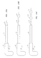
- FIG. 6 shows an alternate embodiment of the occlusion device of the present invention which comprises an occluder element and a fixation element in which the fixation element comprises a looped wire.
- FIG. 7 shows a variation of the embodiment of FIG. 6 in which the fixation element comprises two looped wires.
- FIG. 8 shows a fixation enhancing attachment which may be added to the fixation element.
- FIG. 9 is a schematic illustration of a portion of the deployment means used to deliver the occlusion device into the fallopian tube.
- FIGS. 10A-C are sequential illustrations which show the several stages of deployment of the occlusion device.
- FIG. 11 is a schematic illustration which shows the occlusion device of FIG. 6 after it has been deployed in a fallopian tube.
- the occluder 1 comprises a cap 2 , a body 3 , attachment device 4 and plug 5 .
- Cap 2 is provided with through hole 6 .
- the body is in an extended, stressed condition and expansion means 4 is in a collapsed condition.
- FIG. 2 shows occluder 1 with attachment means 4 in their expanded configuration after the lengthening stress on body 3 has been removed.
- the lengthening of body 3 is accomplished by exerting axial force on plug 5 .
- plug 5 assumes its unstressed shorter configuration as shown in FIG. 2 and plug 5 moves into through hole 6 such that there is no longer an opening in cap 2 .
- the body 3 may be made of nitinol metal while cap 2 and plug 5 may be made from a suitable polymer material.
- FIG. 3 shows the occluder in combination with a delivery means comprising grasper 7 and plunger 8 .
- plunger 8 pushes on plug 5 to cause the body 3 to assume its extended, stressed configuration and causes grasper 7 to engage cap 2 .
- FIG. 5 shows the occluder device after installation with attachment means 4 engaging the wall of fallopian tube 9 and cap 2 sealing the fallopian tube at uterus wall 10 . Once deployed, the device achieves virtually instant sterilization.
- the occluder device has a distal portion which is the occluder element and a proximal portion which is the fixation element.
- the occluder element comprises a tubular portion 11 which is preferably fabricated from a soft polymeric or elastomeric material which has a distal end region 12 with a relatively narrow diameter.
- Located proximally to the distal region 12 are a series of spaced ribs 13 - 16 which have progressively increasing diameters.
- the portion of the occluder element extending from the narrow diameter tip to the largest diameter rib 16 may be hollow or solid. The number of ribs shown in FIG.
- a fixation element 17 which has a distal portion 18 and a proximal portion 19 extends from a point proximal to the proximal end of the occlusion element 11 to a point in the region of the distal end of the occluding element, typically in the region of ridge 16 .
- the distal end 18 of the fixation element may comprise an enlarged loop as shown in FIG. 6 or may have any other suitable configuration.
- a proximal portion 19 of the fixation element 17 preferably bows outwardly as shown in FIG. 6 with a straight portion 20 proximal to the bowed portion 19 .
- the bowed portion 19 of the fixation element is fabricated from a resilient or elastic material which can be deformed such that it is in alignment with straight portions 20 when constrained by a sleeve (not shown) and which will revert to its bowed configuration when the constraint is removed as shown in FIG. 6 .
- a tissue-engaging element 21 can be attached to the bowed portions 19 .
- the fixation device may have the configuration of a flared cylinder as shown in FIG. 6 or it can have other configurations such as a barb, hook, or other projection including the type shown as element 4 in FIG. 2 hereof.
- FIG. 7 illustrates an occlusion device similar to that illustrated in FIG. 6 and the same reference numerals are used for the same elements. However, in FIG. 7 , the illustrated embodiment has a fixation element comprising two looped wires rather than one looped wire as shown in FIG. 6 .
- FIG. 8 is a cross-sectional view of fixation enhancing attachment 21 which has flared ends 22 .
- Deployment of the occlusion devices of FIGS. 6 and 7 is accomplished by using a delivery device comprising two sleeves, an inner sleeve or tube which abuts the proximal end of occlusion element 11 and which constrains the bowed portions 19 of fixation element 17 such that they are aligned with proximal portions 20 .
- a second outer sleeve or tube is positioned over occlusion element 11 and over the inner sleeve such that the distal end of the outer sleeve abuts the largest diameter rib 16 .
- the outer sleeve is attached to a handle and is flexible.
- the occlusion device is deployed in conjunction with the use of a hysteroscope which permits visualization of the target fallopian tube and which has a separate lumen adapted for delivery of the occlusion device.
- a hysteroscope which permits visualization of the target fallopian tube and which has a separate lumen adapted for delivery of the occlusion device.
- the occlusion device can be inserted into the fallopian tube such that, preferably, the insertion is deep enough for the proximal end 20 of the fixation device to be located within the fallopian tube.
- the outer and inner tubes are then removed such that the outer tube no longer contacts the occlusion device and such that the bowed portions 19 of the fixation element 17 are free to bow outwardly into contact with the tissue of the fallopian tube. If the optional fixation elements 21 are used, they will also be brought into contact with the tissue of the fallopian tube.
- the occlusion device of FIGS. 6 and 7 will immediately occlude the fallopian tube such that the waiting time associated with other fallopian tube occluders before they are effective in occluding a fallopian tube is not required.
- the fixation element 17 can be made out of any suitable resilient or elastic material which may be either metal or polymeric, e.g., metals such as nitinol, stainless steel, plastic, reinforced plastics or other suitable materials may be used.
- metals such as nitinol, stainless steel, plastic, reinforced plastics or other suitable materials
- polymeric materials which may be used are included polyimides, polyolefins, polycarbonates, polyesters, polyamides, polyurethanes, synthetic rubbers, etc.
- the occlusion element can be made from a wide variety of materials.
- this element is made from a relatively soft material which may be rubber, synthetic rubber, a foam material which may be fabricated from the polymers identified above or from other materials.
- the occlusion element may also be made from metal, but a non-metal material is preferred for most uses.
- a material may be added to the outside of the occlusion element which will promote scarring, typically by physical irritation of the fallopian tube tissue or by other scarring mechanisms which may include chemical compounds, to further insure the integrity of the occlusion of the fallopian tube.
- Shape-memory metals or polymers are preferred for fabricating the fixation element 17 .
- These shape-memory materials may be composites, e.g., polymers which contain particulate or other additives, such as carbon particles or fibers, and may be combinations of metal and polymer, such as a coated metal.
- the shape memory may be temperature dependent, i.e., actuated by heating or other energy input, or may be mechanical in nature. Such materials are well known to those skilled in the art.
- FIG. 9 is a schematic illustration of the delivery system of the present invention.
- inner tube 24 compresses the bowed portions 19 of the fixation element such that the bowed portions are aligned with the proximal portions 20 .
- Outer sleeve 25 functions as a pusher element and is connected to a handle (not shown).
- the outer sleeve 25 is dimensioned so that it will fit in the additional lumen in a hysteroscope and, when pushed distally by applying force to the handle to which it is attached, will advance the occluding element into the fallopian tube. Once the desired location is achieved, outer sleeve 25 is removed.
- inner sleeve 24 which abuts the proximal end 23 of the occlusion element is also removed by pulling it in a proximal direction.
- inner sleeve 24 is removed, bowed portion 19 of the fixation element will expand outwardly into the tissue of the fallopian tube to effectively hold the device in place.
- FIGS. 10A-C are sequential schematic drawings which further illustrate delivery of the occlusion device.
- element 26 is a handle which slidably receives outer sleeve 25 .
- trigger 27 When trigger 27 is pulled, it slides outer sleeve 25 proximally away from the occlusion device to deploy it in the fallopian tube.
- Inner sleeve 24 is then also moved proximally to release bowed portions 19 of the fixation element as shown in FIG. 10C .
- FIG. 11 is a schematic illustration of the occlusion element 11 deployed in fallopian tube 28 with the bowed portion 19 of the fixation element engaged with the tissue of fallopian tube 28 .
- the bowed portion 19 of the fixation element would penetrate the fallopian tube tissue and the occluder element would be large enough to cause the contour of the fallopian tube to be altered to be in a satisfactory degree of confirmation to the shape of the occluder device to assure effective occlusion.
Abstract
A device for occluding body lumens such as fallopian tubes which has an occluder element which has a lumen and a fixation element located in the lumen of the occluder element. The fixation element has at least one looped wire which has a proximal region which is biased radially outwardly and be constrained prior to deployment of the device.
Description
The application claims priority to U.S. provisional patent application Ser. No. 60/821,238 filed on Aug. 2, 2006 and is a divisional of U.S. application Ser. No. 11/833,182 filed on Aug. 2, 2007 now U.S. Pat. No. 7,647,930, which are fully incorporated herein by reference.
The present invention relates generally to contraception, and more particularly, to intrafallopian contraceptive devices and non-surgical methods for their delivery.
The art to which the present invention is directed is described in United States Published Patent Application No. 2005/0172972, the entirety of which is incorporated herein by reference.
One embodiment disclosed herein comprises a cap and a body. The body is provided with expandable attachment means which collapse when the device is placed under axial stress. When the stress is removed, the compressed attachment means expand. The device can be used to occlude the fallopian tube without perforating it. Another embodiment comprises at least one looped wire adapted to be deployed within a fallopian tube.
The device, and its deployment in this manner, achieve virtually instant sterilization.
As shown in FIG. 1 , the occluder 1 comprises a cap 2, a body 3, attachment device 4 and plug 5. Cap 2 is provided with through hole 6. As shown, the body is in an extended, stressed condition and expansion means 4 is in a collapsed condition.
As can be seen in a comparison of FIG. 2 with FIG. 1 , the lengthening of body 3 is accomplished by exerting axial force on plug 5. When that force is removed, plug 5 assumes its unstressed shorter configuration as shown in FIG. 2 and plug 5 moves into through hole 6 such that there is no longer an opening in cap 2. The body 3 may be made of nitinol metal while cap 2 and plug 5 may be made from a suitable polymer material.
As shown in FIG. 4 , when plunger 8 is retracted, body 3 shortens and attachment members 4 assume their expanded configuration. This shortening of body 3 moves plug 5 into the through hole 6 in cap 2.
An alternate embodiment of the occluder device of the present invention is shown in FIG. 6 . In this embodiment, the occluder device has a distal portion which is the occluder element and a proximal portion which is the fixation element. The occluder element comprises a tubular portion 11 which is preferably fabricated from a soft polymeric or elastomeric material which has a distal end region 12 with a relatively narrow diameter. Located proximally to the distal region 12 are a series of spaced ribs 13-16 which have progressively increasing diameters. The portion of the occluder element extending from the narrow diameter tip to the largest diameter rib 16 may be hollow or solid. The number of ribs shown in FIG. 6 is exemplary only and there may be a lesser or greater number of ribs. Each of the ribs plays a role in occluding a fallopian tube, but the largest diameter rib is the primary occluding element. A fixation element 17 which has a distal portion 18 and a proximal portion 19 extends from a point proximal to the proximal end of the occlusion element 11 to a point in the region of the distal end of the occluding element, typically in the region of ridge 16. The distal end 18 of the fixation element may comprise an enlarged loop as shown in FIG. 6 or may have any other suitable configuration. A proximal portion 19 of the fixation element 17 preferably bows outwardly as shown in FIG. 6 with a straight portion 20 proximal to the bowed portion 19. As will be described in more detail below, the bowed portion 19 of the fixation element is fabricated from a resilient or elastic material which can be deformed such that it is in alignment with straight portions 20 when constrained by a sleeve (not shown) and which will revert to its bowed configuration when the constraint is removed as shown in FIG. 6 . Optionally, a tissue-engaging element 21 can be attached to the bowed portions 19. For example, the fixation device may have the configuration of a flared cylinder as shown in FIG. 6 or it can have other configurations such as a barb, hook, or other projection including the type shown as element 4 in FIG. 2 hereof.
Deployment of the occlusion devices of FIGS. 6 and 7 is accomplished by using a delivery device comprising two sleeves, an inner sleeve or tube which abuts the proximal end of occlusion element 11 and which constrains the bowed portions 19 of fixation element 17 such that they are aligned with proximal portions 20. A second outer sleeve or tube is positioned over occlusion element 11 and over the inner sleeve such that the distal end of the outer sleeve abuts the largest diameter rib 16. The outer sleeve is attached to a handle and is flexible. Preferably, the occlusion device is deployed in conjunction with the use of a hysteroscope which permits visualization of the target fallopian tube and which has a separate lumen adapted for delivery of the occlusion device. Thus, by first visualizing the fallopian tube and then manipulating the handle attached to the outer tube of delivery device, the occlusion device can be inserted into the fallopian tube such that, preferably, the insertion is deep enough for the proximal end 20 of the fixation device to be located within the fallopian tube. The outer and inner tubes are then removed such that the outer tube no longer contacts the occlusion device and such that the bowed portions 19 of the fixation element 17 are free to bow outwardly into contact with the tissue of the fallopian tube. If the optional fixation elements 21 are used, they will also be brought into contact with the tissue of the fallopian tube.
As with the device shown in FIGS. 1-5 , the occlusion device of FIGS. 6 and 7 will immediately occlude the fallopian tube such that the waiting time associated with other fallopian tube occluders before they are effective in occluding a fallopian tube is not required.
The fixation element 17 can be made out of any suitable resilient or elastic material which may be either metal or polymeric, e.g., metals such as nitinol, stainless steel, plastic, reinforced plastics or other suitable materials may be used. Among the polymeric materials which may be used are included polyimides, polyolefins, polycarbonates, polyesters, polyamides, polyurethanes, synthetic rubbers, etc. Similarly, the occlusion element can be made from a wide variety of materials. Preferably, this element is made from a relatively soft material which may be rubber, synthetic rubber, a foam material which may be fabricated from the polymers identified above or from other materials. The occlusion element may also be made from metal, but a non-metal material is preferred for most uses.
Furthermore, a material may be added to the outside of the occlusion element which will promote scarring, typically by physical irritation of the fallopian tube tissue or by other scarring mechanisms which may include chemical compounds, to further insure the integrity of the occlusion of the fallopian tube.
Shape-memory metals or polymers are preferred for fabricating the fixation element 17. These shape-memory materials may be composites, e.g., polymers which contain particulate or other additives, such as carbon particles or fibers, and may be combinations of metal and polymer, such as a coated metal. The shape memory may be temperature dependent, i.e., actuated by heating or other energy input, or may be mechanical in nature. Such materials are well known to those skilled in the art.
The foregoing description of specific embodiments exemplifies the present invention and is but one embodiment thereof. Thus, it is to be understood that the scope of this invention is defined solely by the appended claims.
Claims (9)
1. A device for occluding a body lumen or passageway comprising an elongate member having a distal portion and a proximal portion,
the distal portion of said member comprising an occluder element having a lumen and the proximal portion comprising a fixation element comprising at least one looped wire at its distal end,
said at least one looped wire having two proximal wire portions in a proximal end region of the fixation element,
said occluder element comprising an elongate tube having a distal end region having a narrower diameter than the diameter of the proximal end region, said distal end region comprising a plurality of spaced circumpherential ribs,
the proximal region of said fixation element extending proximally of the proximal end of said occluding element and the at least one looped wire at the distal end of said fixation element extending distally within the lumen of said occluding element to a location in the region of at least one of said ribs, and said fixation element being configured such that the proximal regions thereof have a portion which is biased radially outwardly but which can be constrained to be generally aligned with portions of the wires extending distally within the occluder element, said proximal region of said fixation element being adapted to fixedly engage tissue when in the unconstrained condition and to seal the body lumen.
2. The device of claim 1 , wherein the occluder element is located in a delivery device which radially constrains the radially biased portion of the fixation element.
3. The device of claim 2 , wherein the delivery device is provided with a pusher to move the occluder element distally out of the delivery device.
4. The device of claim 1 , wherein said proximal region of said fixation element is provided with a fixation enhancement member.
5. The device of claim 1 , wherein the outer surface of the occluder element is provided with a scar-promoting material.
6. The device of claim 1 , wherein said fixation element comprises a plurality of looped wires.
7. The device of claim 1 , wherein said occluder element comprises a polymer.
8. The device of claim 1 , wherein the occluder element has a closed distal end.
9. The device of claim 1 , wherein the occluder element has an open proximal end.
Priority Applications (1)
| Application Number | Priority Date | Filing Date | Title |
|---|---|---|---|
| US12/582,937 US9027563B2 (en) | 2006-08-02 | 2009-10-21 | Fallopian tube occlusion devices and methods |
Applications Claiming Priority (3)
| Application Number | Priority Date | Filing Date | Title |
|---|---|---|---|
| US82123806P | 2006-08-02 | 2006-08-02 | |
| US11/833,182 US7647930B2 (en) | 2006-08-02 | 2007-08-02 | Fallopian tube occlusion devices and methods |
| US12/582,937 US9027563B2 (en) | 2006-08-02 | 2009-10-21 | Fallopian tube occlusion devices and methods |
Related Parent Applications (1)
| Application Number | Title | Priority Date | Filing Date |
|---|---|---|---|
| US11/833,182 Division US7647930B2 (en) | 2006-08-02 | 2007-08-02 | Fallopian tube occlusion devices and methods |
Publications (2)
| Publication Number | Publication Date |
|---|---|
| US20100037900A1 US20100037900A1 (en) | 2010-02-18 |
| US9027563B2 true US9027563B2 (en) | 2015-05-12 |
Family
ID=39187282
Family Applications (2)
| Application Number | Title | Priority Date | Filing Date |
|---|---|---|---|
| US11/833,182 Expired - Fee Related US7647930B2 (en) | 2006-08-02 | 2007-08-02 | Fallopian tube occlusion devices and methods |
| US12/582,937 Expired - Fee Related US9027563B2 (en) | 2006-08-02 | 2009-10-21 | Fallopian tube occlusion devices and methods |
Family Applications Before (1)
| Application Number | Title | Priority Date | Filing Date |
|---|---|---|---|
| US11/833,182 Expired - Fee Related US7647930B2 (en) | 2006-08-02 | 2007-08-02 | Fallopian tube occlusion devices and methods |
Country Status (1)
| Country | Link |
|---|---|
| US (2) | US7647930B2 (en) |
Families Citing this family (13)
| Publication number | Priority date | Publication date | Assignee | Title |
|---|---|---|---|---|
| US20100006105A1 (en) * | 2008-07-08 | 2010-01-14 | Carter Phillip J | Apparatus and methods for occluding a fallopian tube |
| US8201562B2 (en) * | 2008-12-02 | 2012-06-19 | Odrich Steven | Multi-piece punctal plug |
| WO2012002944A1 (en) | 2010-06-29 | 2012-01-05 | Artventive Medical Group, Inc. | Reducing flow through a tubular structure |
| US9247942B2 (en) | 2010-06-29 | 2016-02-02 | Artventive Medical Group, Inc. | Reversible tubal contraceptive device |
| US9149277B2 (en) | 2010-10-18 | 2015-10-06 | Artventive Medical Group, Inc. | Expandable device delivery |
| US8984733B2 (en) | 2013-02-05 | 2015-03-24 | Artventive Medical Group, Inc. | Bodily lumen occlusion |
| US9095344B2 (en) | 2013-02-05 | 2015-08-04 | Artventive Medical Group, Inc. | Methods and apparatuses for blood vessel occlusion |
| US9737306B2 (en) | 2013-06-14 | 2017-08-22 | Artventive Medical Group, Inc. | Implantable luminal devices |
| US9737308B2 (en) | 2013-06-14 | 2017-08-22 | Artventive Medical Group, Inc. | Catheter-assisted tumor treatment |
| US9636116B2 (en) | 2013-06-14 | 2017-05-02 | Artventive Medical Group, Inc. | Implantable luminal devices |
| US10149968B2 (en) | 2013-06-14 | 2018-12-11 | Artventive Medical Group, Inc. | Catheter-assisted tumor treatment |
| US10363043B2 (en) | 2014-05-01 | 2019-07-30 | Artventive Medical Group, Inc. | Treatment of incompetent vessels |
| US10813644B2 (en) | 2016-04-01 | 2020-10-27 | Artventive Medical Group, Inc. | Occlusive implant and delivery system |
Citations (8)
| Publication number | Priority date | Publication date | Assignee | Title |
|---|---|---|---|---|
| US5728134A (en) | 1996-09-17 | 1998-03-17 | Barak; Shlomo | Method and apparatus for hemostasis |
| US6695867B2 (en) * | 2002-02-21 | 2004-02-24 | Integrated Vascular Systems, Inc. | Plunger apparatus and methods for delivering a closure device |
| US6763833B1 (en) | 1999-08-23 | 2004-07-20 | Conceptus, Inc. | Insertion/deployment catheter system for intrafallopian contraception |
| US6871650B1 (en) | 1995-06-07 | 2005-03-29 | Conceptus, Inc. | Contraceptive transcervical fallopian tube occlusion devices and their delivery |
| US20050172972A1 (en) | 1995-06-07 | 2005-08-11 | Conceptus, Inc. | Contraceptive transcervical fallopian tube occlusion devices and methods |
| US7220259B2 (en) * | 1997-06-05 | 2007-05-22 | Adiana, Inc. | Method and apparatus for tubal occlusion |
| US20090143815A1 (en) | 2007-11-30 | 2009-06-04 | Boston Scientific Scimed, Inc. | Apparatus and Method for Sealing a Vessel Puncture Opening |
| US7771452B2 (en) * | 2005-07-12 | 2010-08-10 | Cook Incorporated | Embolic protection device with a filter bag that disengages from a basket |
Family Cites Families (6)
| Publication number | Priority date | Publication date | Assignee | Title |
|---|---|---|---|---|
| US3397699A (en) * | 1966-05-05 | 1968-08-20 | Gerald C. Kohl | Retaining catheter having resiliently biased wing flanges |
| US4677967A (en) * | 1984-11-01 | 1987-07-07 | New Mexico State University Foundation | Intravaginal anchor |
| US5935137A (en) * | 1997-07-18 | 1999-08-10 | Gynecare, Inc. | Tubular fallopian sterilization device |
| US6780197B2 (en) * | 2000-01-05 | 2004-08-24 | Integrated Vascular Systems, Inc. | Apparatus and methods for delivering a vascular closure device to a body lumen |
| US6763853B1 (en) * | 2002-03-01 | 2004-07-20 | Rsb Pipe Corporation, Inc. | Lightweight conduit |
| NL1026102C2 (en) * | 2004-05-03 | 2005-11-07 | Doorzand Guardian Angel B V | Blocking device for fallopian tubes and insertion device therefor. |
-
2007
- 2007-08-02 US US11/833,182 patent/US7647930B2/en not_active Expired - Fee Related
-
2009
- 2009-10-21 US US12/582,937 patent/US9027563B2/en not_active Expired - Fee Related
Patent Citations (8)
| Publication number | Priority date | Publication date | Assignee | Title |
|---|---|---|---|---|
| US6871650B1 (en) | 1995-06-07 | 2005-03-29 | Conceptus, Inc. | Contraceptive transcervical fallopian tube occlusion devices and their delivery |
| US20050172972A1 (en) | 1995-06-07 | 2005-08-11 | Conceptus, Inc. | Contraceptive transcervical fallopian tube occlusion devices and methods |
| US5728134A (en) | 1996-09-17 | 1998-03-17 | Barak; Shlomo | Method and apparatus for hemostasis |
| US7220259B2 (en) * | 1997-06-05 | 2007-05-22 | Adiana, Inc. | Method and apparatus for tubal occlusion |
| US6763833B1 (en) | 1999-08-23 | 2004-07-20 | Conceptus, Inc. | Insertion/deployment catheter system for intrafallopian contraception |
| US6695867B2 (en) * | 2002-02-21 | 2004-02-24 | Integrated Vascular Systems, Inc. | Plunger apparatus and methods for delivering a closure device |
| US7771452B2 (en) * | 2005-07-12 | 2010-08-10 | Cook Incorporated | Embolic protection device with a filter bag that disengages from a basket |
| US20090143815A1 (en) | 2007-11-30 | 2009-06-04 | Boston Scientific Scimed, Inc. | Apparatus and Method for Sealing a Vessel Puncture Opening |
Non-Patent Citations (1)
| Title |
|---|
| Office Action dated Nov. 10, 2014, from corresponding JP application No. 2012-555194. |
Also Published As
| Publication number | Publication date |
|---|---|
| US20100037900A1 (en) | 2010-02-18 |
| US20080066763A1 (en) | 2008-03-20 |
| US7647930B2 (en) | 2010-01-19 |
Similar Documents
| Publication | Publication Date | Title |
|---|---|---|
| US9027563B2 (en) | Fallopian tube occlusion devices and methods | |
| US20220125449A1 (en) | Retrieval device | |
| US11129617B2 (en) | Tissue anchor for securing tissue layers | |
| US8016838B2 (en) | Retrieval device | |
| US20080147100A1 (en) | Aneurysm neck obstruction device | |
| CN112656461B (en) | Plugging device | |
| BR102014005566A2 (en) | STENT APPLICATION SYSTEM AND METHOD | |
| US20160166427A1 (en) | Occlusion device with openable channel | |
| JP4709822B2 (en) | Biological tissue clip device | |
| US9724101B2 (en) | Lumen occluding device, delivery catheter and method | |
| US8875712B2 (en) | System and method for occluding a reproductive body lumen | |
| JP2013508010A (en) | Urethral anastomosis device | |
| US20150238194A1 (en) | Hemostasis devices and methods utilizing mechanical methods | |
| EP3119289B1 (en) | Devices for lumen occlusion | |
| JP7305800B2 (en) | Reloadable clip with flared capsule deformation | |
| US9592148B2 (en) | Acute and permanent occlusion device, delivery catheter and method | |
| US9597223B2 (en) | Reversible acute occlusion implant, delivery catheter and method |
Legal Events
| Date | Code | Title | Description |
|---|---|---|---|
| STCF | Information on status: patent grant |
Free format text: PATENTED CASE |
|
| FEPP | Fee payment procedure |
Free format text: MAINTENANCE FEE REMINDER MAILED (ORIGINAL EVENT CODE: REM.); ENTITY STATUS OF PATENT OWNER: SMALL ENTITY |
|
| LAPS | Lapse for failure to pay maintenance fees |
Free format text: PATENT EXPIRED FOR FAILURE TO PAY MAINTENANCE FEES (ORIGINAL EVENT CODE: EXP.); ENTITY STATUS OF PATENT OWNER: SMALL ENTITY |
|
| STCH | Information on status: patent discontinuation |
Free format text: PATENT EXPIRED DUE TO NONPAYMENT OF MAINTENANCE FEES UNDER 37 CFR 1.362 |
|
| FP | Expired due to failure to pay maintenance fee |
Effective date: 20190512 |