US9027668B2 - Control system for high power laser drilling workover and completion unit - Google Patents
Control system for high power laser drilling workover and completion unit Download PDFInfo
- Publication number
- US9027668B2 US9027668B2 US13/403,692 US201213403692A US9027668B2 US 9027668 B2 US9027668 B2 US 9027668B2 US 201213403692 A US201213403692 A US 201213403692A US 9027668 B2 US9027668 B2 US 9027668B2
- Authority
- US
- United States
- Prior art keywords
- laser
- high power
- control
- umbilical
- module
- Prior art date
- Legal status (The legal status is an assumption and is not a legal conclusion. Google has not performed a legal analysis and makes no representation as to the accuracy of the status listed.)
- Active, expires
Links
Images


Classifications
-
- E—FIXED CONSTRUCTIONS
- E21—EARTH DRILLING; MINING
- E21B—EARTH DRILLING, e.g. DEEP DRILLING; OBTAINING OIL, GAS, WATER, SOLUBLE OR MELTABLE MATERIALS OR A SLURRY OF MINERALS FROM WELLS
- E21B7/00—Special methods or apparatus for drilling
- E21B7/14—Drilling by use of heat, e.g. flame drilling
-
- E—FIXED CONSTRUCTIONS
- E21—EARTH DRILLING; MINING
- E21B—EARTH DRILLING, e.g. DEEP DRILLING; OBTAINING OIL, GAS, WATER, SOLUBLE OR MELTABLE MATERIALS OR A SLURRY OF MINERALS FROM WELLS
- E21B44/00—Automatic control systems specially adapted for drilling operations, i.e. self-operating systems which function to carry out or modify a drilling operation without intervention of a human operator, e.g. computer-controlled drilling systems; Systems specially adapted for monitoring a plurality of drilling variables or conditions
-
- E—FIXED CONSTRUCTIONS
- E21—EARTH DRILLING; MINING
- E21B—EARTH DRILLING, e.g. DEEP DRILLING; OBTAINING OIL, GAS, WATER, SOLUBLE OR MELTABLE MATERIALS OR A SLURRY OF MINERALS FROM WELLS
- E21B7/00—Special methods or apparatus for drilling
- E21B7/14—Drilling by use of heat, e.g. flame drilling
- E21B7/15—Drilling by use of heat, e.g. flame drilling of electrically generated heat
Definitions
- the present inventions relate to high power laser systems and units and high power laser-mechanical tools systems and units, such as for example drilling, workover and completion, perforating, decommissioning, cleaning, mining, and laser pigging units; and, in particular to control systems and monitoring systems for high power laser systems and units.
- high power laser energy means a laser beam having at least about 1 kW (kilowatt) of power.
- greater distances means at least about 500 m (meter).
- substantial loss of power means a loss of power of more than about 3.0 dB/km (decibel/kilometer) for a selected wavelength.
- substantially power transmission means at least about 50% transmittance.
- Pipeline should be given its broadest possible meaning, and includes any structure that contains a channel having a length that is many orders of magnitude greater than its cross-sectional area and which is for, or capable of, transporting a material along at least a portion of the length of the channel.
- Pipelines may be many miles long and may be many hundreds of miles long.
- Pipelines may be located below the earth, above the earth, under water, within a structure, or combinations of these and other locations.
- Pipelines may be made from metal, steel, plastics, ceramics, composite materials, or other materials and compositions know to the pipeline arts and may have external and internal coatings, known to the pipeline arts. In general, pipelines may have internal diameters that range from about 2 to about 60 inches although larger and smaller diameters may be utilized.
- Pipelines may be used to transmit numerous types of materials, in the form of a liquid, gas, fluidized solid, slurry or combinations thereof.
- pipelines may carry hydrocarbons; chemicals; oil; petroleum products; gasoline; ethanol; biofuels; water; drinking water; irrigation water; cooling water; water for hydroelectric power generation; water, or other fluids for geothermal power generation; natural gas; paints; slurries, such as mineral slurries, coal slurries, pulp slurries; and ore slurries; gases, such as nitrogen and hydrogen; cosmetics; pharmaceuticals; and food products, such as beer.
- slurries such as mineral slurries, coal slurries, pulp slurries; and ore slurries
- gases such as nitrogen and hydrogen
- cosmetics such as pharmaceuticals
- food products such as beer.
- Pipelines may be, in part, characterized as gathering pipelines, transportation pipelines and distribution pipelines, although these characterizations may be blurred and may not cover all potential types of pipelines. Gathering pipelines are a number of smaller interconnected pipelines that form a network of pipelines for bringing together a number of sources, such as for example bringing together hydrocarbons being produced from a number of wells.
- Transportation pipelines are what can be considered as a traditional pipeline for moving products over longer distances for example between two cities, two countries, and a production location and a shipping, storage or distribution location.
- the Alaskan oil pipeline is an example of a transportation pipeline.
- Distribution pipelines can be small pipelines that are made up of several interconnected pipelines and are used for the distribution to for example an end user, of the material that is being delivered by the pipeline, such as for example the feeder lines used to provide natural gas to individual homes.
- pipeline includes all of these and other characterizations of pipelines that are known to or used in the pipeline arts.
- pig is to be given its broadest possible meaning and includes all devices that are known as or referred to in the pipeline arts as a “pig” and would include any device that is inserted into and moved along at least a portion of the length of a pipeline to perform activities such as inspecting, cleaning, measuring, analyzing, maintaining, welding, assembling, or other activities known to the pipeline arts.
- pigs are devices that may be unitary devices, as simple as a foam or metal ball, or a complex multi-component device such as a magnetic flux leakage pig.
- pigs are devices that when inserted in the pipeline travel along its length and are moved through the pipeline by the flow of the material within the pipe.
- Pigs may generally be characterized as utility and in-line inspection pigs, although these characterizations may be blurred and may not cover all potential types of pigs.
- Utility pigs perform such functions as for example cleaning, separation of products and removal of water.
- In-line inspection pigs would include gauge pigs, as well as, more complex pigs, which may also be referred to by those of skill in the art as instrument pigs, intelligent pigs or smart pigs.
- Smart pigs perform such functions as for example supplying information on the condition of the pipeline, as well as on the extent and location of any problems with the pipeline. Pigs are used both during the construction and during the operational life of the pipelines. Pigs may also be used in the decommissioning of a pipeline and its removal.
- earth should be given its broadest possible meaning, and includes, the ground, all natural materials, such as rocks, and artificial materials, such as concrete, that are or may be found in the ground, including without limitation rock layer formations, such as, granite, basalt, sandstone, dolomite, sand, salt, limestone, rhyolite, quartzite and shale rock.
- rock layer formations such as, granite, basalt, sandstone, dolomite, sand, salt, limestone, rhyolite, quartzite and shale rock.
- borehole should be given it broadest possible meaning and includes any opening that is created in a material, a work piece, a surface, the earth, a structure (e.g., building, protected military installation, nuclear plant, offshore platform, or ship), or in a structure in the ground, (e.g., foundation, roadway, airstrip, cave or subterranean structure) that is substantially longer than it is wide, such as a well, a well bore, a well hole, a micro hole, slimhole, a perforation and other terms commonly used or known in the arts to define these types of narrow long passages.
- Wells would further include exploratory, production, abandoned, reentered, reworked, and injection wells.
- boreholes are generally oriented substantially vertically, they may also be oriented on an angle from vertical, to and including horizontal.
- a borehole can have orientations ranging from 0° i.e., vertical, to 90°,i.e., horizontal and greater than 90° e.g., such as a heel and toe and combinations of these such as for example “U” and “Y” shapes.
- Boreholes may further have segments or sections that have different orientations, they may have straight sections and arcuate sections and combinations thereof; and for example may be of the shapes commonly found when directional drilling is employed.
- the “bottom” of a borehole refers to the end of the borehole, i.e., that portion of the borehole furthest along the path of the borehole from the borehole's opening, the surface of the earth, or the borehole's beginning.
- the terms “side” and “wall” of a borehole should to be given their broadest possible meaning and include the longitudinal surfaces of the borehole, whether or not casing or a liner is present, as such, these terms would include the sides of an open borehole or the sides of the casing that has been positioned within a borehole.
- Boreholes may be made up of a single passage, multiple passages, connected passages and combinations thereof, in a situation where multiple boreholes are connected or interconnected each borehole would have a borehole bottom. Boreholes may be formed in the sea floor, under bodies of water, on land, in ice formations, or in other locations and settings.
- Boreholes are generally formed and advanced by using mechanical drilling equipment having a rotating drilling tool, e.g., a bit.
- a drilling bit is extending to and into the earth and rotated to create a hole in the earth.
- the bit In general, to perform the drilling operation the bit must be forced against the material to be removed with a sufficient force to exceed the shear strength, compressive strength or combinations thereof, of that material.
- the material that is cut from the earth is generally known as cuttings, e.g., waste, which may be chips of rock, dust, rock fibers and other types of materials and structures that may be created by the bit's interactions with the earth.
- cuttings are typically removed from the borehole by the use of fluids, which fluids can be liquids, foams or gases, or other materials know to the art.
- the term “advancing” a borehole should be given its broadest possible meaning and includes increasing the length of the borehole. Thus, by advancing a borehole, provided the orientation is not horizontal, e.g., less than 90° the depth of the borehole may also be increased.
- the true vertical depth (“TVD”) of a borehole is the distance from the top or surface of the borehole to the depth at which the bottom of the borehole is located, measured along a straight vertical line.
- the measured depth (“MD”) of a borehole is the distance as measured along the actual path of the borehole from the top or surface to the bottom.
- the term depth of a borehole will refer to MD.
- a point of reference may be used for the top of the borehole, such as the rotary table, drill floor, well head or initial opening or surface of the structure in which the borehole is placed.
- ream As used herein, unless specified otherwise, the terms “ream”, “reaming”, a borehole, or similar such terms, should be given their broadest possible meaning and includes any activity performed on the sides of a borehole, such as, e.g., smoothing, increasing the diameter of the borehole, removing materials from the sides of the borehole, such as e.g., waxes or filter cakes, and under-reaming.
- the terms “drill bit”, “bit”, “drilling bit” or similar such terms should be given their broadest possible meaning and include all tools designed or intended to create a borehole in an object, a material, a work piece, a surface, the earth or a structure including structures within the earth, and would include bits used in the oil, gas and geothermal arts, such as fixed cutter and roller cone bits, as well as, other types of bits, such as, rotary shoe, drag-type, fishtail, adamantine, single and multi-toothed, cone, reaming cone, reaming, self-cleaning, disc, three-cone, rolling cutter, crossroller, jet, core, impreg and hammer bits, and combinations and variations of the these.
- a fixed cutter bit In general, in a fixed cutter bit there are no moving parts. In these bits drilling occurs when the entire bit is rotated by, for example, a rotating drill string, a mud motor, or other means to turn the bit.
- Fixed cutter bits have cutters that are attached to the bit. These cutters mechanically remove material, advancing the borehole as the bit is turned.
- the cutters in fixed cutter bits can be made from materials such as polycrystalline diamond compact (“PDC”), grit hotpressed inserts (“GHI”), and other materials known to the art or later developed by the art.
- a roller cone bit has one, two, three or more generally conically shaped members, e.g., the roller cones, that are connected to the bit body and which can rotate with respect to the bit.
- the cones rotate and in effect roll around the bottom of the borehole.
- the cones have, for example, tungsten carbide inserts (“TCI”) or milled teeth (“MT”), which contact the bottom, or other surface, of the borehole to mechanically remove material and advance the borehole as the bit it turned.
- Mechanical bits cut rock by applying crushing (compressive) and/or shear stresses created by rotating a cutting surface against the rock and placing a large amount of WOB.
- this action is primarily by shear stresses and in the case of roller cone bits this action is primarily by crushing (compression) and shearing stresses.
- the WOB applied to an 83 ⁇ 4′′ PDC bit may be up to 15,000 lbs
- the WOB applied to an 83 ⁇ 4′′ roller cone bit may be up to 60,000 lbs.
- the effective drilling rate is based upon the total time necessary to complete the borehole and, for example, would include time spent tripping in and out of the borehole, as well as, the time for repairing or replacing damaged and worn bits.
- the term “drill pipe” should be given its broadest possible meaning and includes all forms of pipe used for drilling activities; and refers to a single section or piece of pipe, as well as, multiple pipes or sections.
- the terms “stand of drill pipe,” “drill pipe stand,” “stand of pipe,” “stand” and similar type terms should be given their broadest possible meaning and include two, three or four sections of drill pipe that have been connected, e.g., joined together, typically by joints having threaded connections.
- drill string As used herein, unless specified otherwise, the terms “drill string,” “string,” “string of drill pipe,” string of pipe” and similar type terms should be given their broadest definition and would include a stand or stands joined together for the purpose of being employed in a borehole. Thus, a drill string could include many stands and many hundreds of sections of drill pipe.
- tubular should be given its broadest possible meaning and includes drill pipe, casing, riser, coiled tube, composite tube, vacuum insulated tubing (“VIT”), production tubing and any similar structures having at least one channel therein that are, or could be used, in the drilling industry.
- VIT vacuum insulated tubing
- joint should be given its broadest possible meaning and includes all types of devices, systems, methods, structures and components used to connect tubulars together such as for example, threaded pipe joints and bolted flanges.
- the joint section typically has a thicker wall than the rest of the drill pipe.
- the thickness of the wall of tubular is the thickness of the material between the internal diameter of the tubular and the external diameter of the tubular.
- BOP blowout preventer
- BOP stack should be given their broadest possible meaning, and include: (i) devices positioned at or near the borehole surface, e.g., the surface of the earth including dry land or the seafloor, which are used to contain or manage pressures or flows associated with a borehole; (ii) devices for containing or managing pressures or flows in a borehole that are associated with a subsea riser or a connector; (iii) devices having any number and combination of gates, valves or elastomeric packers for controlling or managing borehole pressures or flows; (iv) a subsea BOP stack, which stack could contain, for example, ram shears, pipe rams, blind rams and annular preventers; and, (v) other such similar combinations and assemblies of flow and pressure management devices to control borehole pressures, flows or both and, in particular, to control or manage emergency flow or pressure situations.
- offshore and “offshore drilling activities” and similar such terms are used in their broadest sense and would include drilling activities on, or in, any body of water, whether fresh or salt water, whether manmade or naturally occurring, such as for example rivers, lakes, canals, inland seas, oceans, seas, bays and gulfs, such as the Gulf of Mexico.
- offshore drilling rig is to be given its broadest possible meaning and would include fixed towers, tenders, platforms, barges, jack-ups, floating platforms, drill ships, dynamically positioned drill ships, semi-submersibles and dynamically positioned semi-submersibles.
- the term “seafloor” is to be given its broadest possible meaning and would include any surface of the earth that lies under, or is at the bottom of, any body of water, whether fresh or salt water, whether manmade or naturally occurring.
- the terms “decommissioning,” “plugging” and “abandoning” and similar such terms should be given their broadest possible meanings and would include activities relating to the cutting and removal of casing and other tubulars from a well (above the surface of the earth, below the surface of the earth and both), modification or removal of structures, apparatus, and equipment from a site to return the site to a prescribed condition, the modification or removal of structures, apparatus, and equipment that would render such items in a prescribe inoperable condition, the modification or removal of structures, apparatus, and equipment to meet environmental, or regulatory considerations present at the end of such items useful, economical or intended life cycle.
- Such activities would include for example the removal of onshore, e.g., land based, structures above the earth, below the earth and combinations of these, such as e.g., the removal of tubulars from within a well in preparation for plugging.
- onshore e.g., land based
- structures above the earth below the earth and combinations of these, such as e.g., the removal of tubulars from within a well in preparation for plugging.
- workover should be given their broadest possible meanings and would include activities that place at or near the completion of drilling a well, activities that take place at or the near the commencement of production from the well, activities that take place on the well when the well is producing or operating well, activities that take place to reopen or reenter an abandoned or plugged well or branch of a well, and would also include for example, perforating, cementing, acidizing, fracturing, pressure testing, the removal of well debris, removal of plugs, insertion or replacement of production tubing, forming windows in casing to drill or complete lateral or branch wellbores, cutting and milling operations in general, insertion of screens, stimulating, cleaning, testing, analyzing and other such activities.
- These terms would further include applying heat, directed energy, preferably in the form of a high power laser beam to heat, melt, soften, activate, vaporize, disengage, desiccate and combinations and variations of these, materials in a well, or other structure, to remove, assist in their removal, cleanout, condition and combinations and variation of these, such materials.
- high power laser units and high power laser systems may be land based, sea based, land and sea based, mobile, containerized, truck based, barge based, vessel based, rig based, fixed and combinations and variations thereof.
- control system for use in activities involving the transmission of high power laser energy over great distance to high power laser tools to perform activities, such as for example, drilling, workover and completion activities in the oil, natural gas and geothermal industries, as well as, activities in other industries, such as the nuclear industry, the chemical industry, the subsea exploration, salvage and construction industry, the pipeline industry, and the military.
- control and monitoring systems are needed when the high power laser energy is transmitted over great distances to small and/or difficult to access locations, positions or environments for activities such as monitoring, cleaning, controlling, assembling, drilling, machining and cutting.
- the present inventions solve these and other needs by providing the articles of manufacture, devices and processes taught herein.
- a system for controlling, operating, or monitoring, a high power laser unit having a source of high power laser energy, a high power optical conveyance device, a high power laser tool, wherein the high power optical conveyance device provides optical communication for a laser beam from the high power laser energy source to be conveyed to the high power laser tool the system having: a control network having a first monitoring device, a second monitoring device; wherein the first monitoring devices is positioned with respect to a location on the unit to detect laser energy; wherein the second monitoring device is positioned with respect to a location on the unit to detect the status of a component of the unit; the first and second monitoring devices, in communication with a controller, wherein at least one of the monitoring devices can send a signal on the network; and, the controller is configured to act upon the signal from the monitoring device and performing a predetermined operation based upon the signal.
- systems and units may also include: where the component is a laser tool and the signal indicates the failure of the laser tool and the operation is sending a signal to shut down the high power laser source; where the signal is from the first or second monitoring device and the operation is to wait for a signal from the other monitoring device; wherein the first monitoring device comprises a photo diode and the second monitoring device comprises a load cell; wherein the component is a laser tool and the signal indicates the position of the tool; where the component is a laser bottom hole assembly having a bit and the signal indicates the RPM of the bit.
- a system for remotely deterring and monitoring the RPM of a down hole tool having: an accelerometer positioned in vibrational communication with a member near the top of a borehole; the member in vibrational communication with a down hole tool as the tool is rotated to advance the borehole; the accelerometer configured to send a signal based upon vibrations associated with the rotation of the down hole tool; and a processor configured to convert the vibration signal to the RPM of the down hole tool as it is rotated to advance the borehole.
- This system may also have the RPM value utilized by a controller in the system to control the RPM of the down hole tool and it may further have the down hole tool being a laser bottom hole assembly.
- a control system for a high power laser unit for performing a laser operation at a remote location having: a first module in communication with a source of high power laser energy, the laser source capable of providing a laser beam having at least 5 kW of power; a second module in communication with a tubing assembly, the tubing assembly having: a tubing having a distal end and a proximal end, and a high power optical fiber having a distal end and a proximal end, wherein the high power optical fiber is associated with the tubing and the high power optical fiber distal end is associated with the tubing distal end; a third module in communication with a high power laser tool, the laser tool in optical association with the distal end of the high power fiber and in mechanical association with the distal end of the tubing; a fourth module in communication with a motive means, the motive means to advancing the distal end of the tubing to a predetermined worksite location; the proximal end of the optical fiber in optical association with
- a control system for a high power laser unit for performing a laser operation at a remote location having: a first module in communication with a source of high power laser energy, the laser source capable of providing a laser beam having at least 5 kW of power; a second module in communication with a tubing assembly, the tubing assembly having: a tubing having a distal end and a proximal end, and a high power optical fiber having a distal end and a proximal end, wherein the high power optical fiber is associated with the tubing and the high power optical fiber distal end is associated with the tubing distal end; a third module in communication with a high power laser tool, the laser tool in optical association with the distal end of the high power fiber and in mechanical association with the distal end of the tubing; a fourth module in communication with a motive means, the motive means to advancing the distal end of the tubing to a predetermined worksite location; the proximal end of the optical fiber in optical association with the
- Such a unit may also include: the control module is associated with a programmable logic controller; the control module is associated with a personal computer; where the tubing is selected from the group including composite tubing, coiled tubing and wireline; wherein the optical fiber has a length selected from the group of length of about 0.5 km, about 1 km, about 2 km, about 3 km and from about 0.5 km to about 5 km; and wherein the laser tool is selected from the group including a laser cutting tool, a laser bottom hole assembly and an electric motor laser bottom hole assembly; where the first, third and control modules reside on a control network, the network and modules configured to send and receive data signals and control signals between the first, third and control modules; where the second, fourth and fifth modules reside on the control network and the network and modules configured to send and receive data signals and control signal between the second, fourth, fifth and control modules; or where a signal is received from the fifth module causing the control to send a signal to the third and fourth modules to stop operation of the tool, and retrieve the tool.
- the tubing is selected
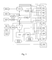
- FIG. 1 is a schematic of the embodiment of the control and monitoring system for the high power laser drilling system of FIG. 4 in accordance with the present invention.
- FIG. 1A is a schematic table for the control and monitoring system of FIG. 1 .
- FIG. 1B is a schematic of an embodiment of an advancement device associated with the control and monitoring system of FIG. 1 .
- FIGS. 1C to 1N are schematics of embodiments of components of the control and monitoring system of FIG. 1 .
- FIGS. 1O to 1R are drawings of embodiments of HMI displays in accordance with the present invention.
- FIG. 2 is schematic view of an embodiment of a mobile laser truck unit in accordance with the present invention.
- FIG. 2A is a schematic of an embodiment of a control and monitoring system for the unit of FIG. 2 , in accordance with the present invention.
- FIG. 2B is a schematic of the control and monitoring system of FIG. 2A .
- FIG. 3 is a schematic view of an embodiment of a control and monitoring system in accordance with the present invention.
- FIG. 4 is a schematic view of an embodiment of a high power laser system deployed in laser activities in the field in accordance with the present invention.
- FIG. 5 is schematic view of an embodiment of a mobile truck laser unit for an electric motor laser bottom hole assembly (“EM-LBHA”) in accordance with the present invention.
- EM-LBHA electric motor laser bottom hole assembly
- FIG. 5A is a schematic of a distributed control system for the laser unit of FIG. 5 .
- FIG. 6 is a schematic view of an embodiment of laser unit as deployed and utilizing an EM-LBHA in accordance with the present invention.
- the present inventions relate to systems for delivering and utilization of high power laser energy, for example at least about 5 kW, at least about 10 kW, at least about 20 kW, at least about 50 kW, and at least about 100 kW.
- the present inventions relate to control and monitoring systems for high power laser units for performing activities such as drilling, working over, completing, cleaning, milling, perforating, monitoring, analyzing, cutting, removing, welding and assembling. More specifically, and by way of example, the present inventions relate to control and monitoring systems for high power energy drilling workover and completion units.
- a control and monitoring system for a high power laser unit or system should preferably address primary functions, components and parameters, preferably key functions, components and parameters, and more preferably all critical functions, components and parameters of the laser unit, including such parameters, which are deemed critical when viewed from operations, productivity and combinations thereof perspective.
- the present inventions contemplate systems that address a single component, function or parameter, less than, or more than all critical components and parameters, only important components and parameters, more than or less than all important components and parameters, and combinations an variations of the foregoing.
- control and monitoring system be fully integrated systems, such that control activities, monitoring activities and data retrieval activities are capable of being performed by a single integrated network, which may have varied individual controls, sensors, monitors and other equipment.
- a fully integrated system a system having sub-systems, a system that is partially integrated, a system that is a distributed control network, a system that is a control network, and an independent system, and combinations and variations thereof, are also contemplated.
- equipment, parameters, and conditions that could be monitored and controlled may include, one or more of the following:
- Laser such as laser operations, laser power output, temperature, back reflections, laser chiller, laser chiller status, laser readiness and laser status. This would include the use of multiple lasers, or laser having multiple modules, as well as, a separate laser unit, such as a laser truck which is later integrated or optically associated with for example a laser tool;
- High power optical fiber such as fiber integrity, break detection, temperature, back reflections, splices, light leakage, and fiber integrity. This would include the use of multiple fibers in parallel, the use of fibers serially, e.g., connecting one component to the next, as for example, with the use of an optical slip ring (“OSR”);
- OSR optical slip ring
- Optical conveyance devices such as a beam switch, coupler, connector, OSR, temperature of these device, cooling and heat management systems for these devices, light leakage from these devices, OSR cooling system, other cooling systems, OSR alignment, beam switch alignment, other optical component alignment, other optical devices where alignment may be an issue, and a spool (or other device to handle the optical cable or conveyance device). This would include the use of multiple such devices both in serial and in parallel. It would also include the monitoring of other support or operating materials needed for the operation of such conveyance devices;
- Advancement devices would include the mechanical components that are used for raising and lower, extending and retracting, moving, and combinations thereof, the optical cable and a high power laser tool that is at the end of the cable, such as for example a spool and injector on a coil tubing unit, or a spool on a wire line unit.
- High power laser tools this would include all of the supporting material needed for a high power laser tool, such as for example fluid flow, e.g., a liquid, compressed air, or N 2 , as the motive fluid for a mud motor, fluid flow to keep the high power laser beam path clean of debris, e.g., a transmissive liquid or fluid, substantially transmissive liquid or fluid, compressed air, N 2 , electric power, RPM (revolutions per minute), TVD, MD, lubrication of tools, temperature of tools and related equipment, and other conditions, or information about the operations of the tool. Further, if the tool has monitoring, measuring or analyzing functions such as MWD, LWD the operation of those functions may be monitored and controlled; and,
- Interlocks such as for example the monitoring, sensing for conditions that are out of set operating parameter, or predictive of conditions becoming out of set operating parameters, and similar types of monitoring and control that will automatically stop or shut down the laser or the unit to prevent a dangerous situation or stop the occurrence of a dangerous situation either for personnel, equipment or both.
- FIGS. 1 and 1A to 1 P an example of an embodiment of a control and monitoring system for a high power laser unit is illustrated in FIGS. 1 and 1A to 1 P, which system could be deployed with a drilling system such as illustrated in FIG. 4 .
- FIG. 1 shows the top-level system configuration for this embodiment.
- FIG. 1A provides a table setting forth the interfaces in this system.
- FIG. 1N provides the overall software implementation and includes the principal systems and their functions for this embodiment.
- this embodiment of a control and monitoring system includes a LabVIEW CompactRIO (“cRIO”) embedded system to perform all critical functions with a PC (personal computer, i.e., a small unit having a processor, memory and an operating system, such as are available from IBM, Dell, and Apple) to provide user interface and data logging capabilities.
- a LabVIEW system is used, other systems of factory and equipment automation and control may also be employed, such as those available from Schneider Electric, Rockwell, Siemens and Opto 22.
- an emphasis should be placed on monitoring of various parameters.
- the system includes for example monitoring the laser back reflection and flow rates of cooling systems.
- the cRIO is interfaced with various instruments to provide monitoring, logging and in some cases control of the instrument to achieve proper operation for drilling or other high power laser activities.
- the CompactRIO contains both an FPGA (Field-Programable Gate Array) and a real-time processor.
- the FPGA handles all input from the sensors and outputs to the laser. If any of the measured values is out of the allowable range, the FPGA drops the power set point to 0 W and engages the laser interlock mechanism.
- the CompactRIO real-time (RT) processor handles all communication between the FPGA and PC, as well as for example, features such as features that cannot be performed on the FPGA directly.
- the RT software initializes the FPGA on start-up and responds to all commands from the PC. For example, when the laser power set point is changed on the PC, this command is sent to the RT software, which communicates the command to the FPGA. In addition to handling commands from the PC, it also communicates the current status to the PC. Finally, the RT software handles the rate of penetration (ROP) calculations and the control loop to control the air flow rate.
- ROIP rate of penetration
- the PC software serves primarily as a user interface to allow an operator to control the system. All relevant set points, limits and controls are accessible by the user via the PC software. Other than sending the set points to the CompactRIO when they are changed, the PC has no interaction with safety mechanisms.
- the PC software shows the current status of all monitored parameters, and stores this data to a user specified data file.
- E-Stops External Emergency Stops
- FIGS. 1 , 1 A, 1 D, and 1 N the overall system schematics, architecture, and functionality is illustrated. Like numbers in FIGS. 1 , and 1 A to 1 N refer to like items.
- FIG. 1 in this embodiment there are eight National Instruments (NI) modules: 9201 Voltage Analog inputs 1001 , 9263 Voltage Analog Outputs 1002 , 9203 Current Analog Inputs 1003 , 9265 Current Analog Outputs 1004 , 9421 10V Digital Inputs 1005 , 9481 Relay Digital Outputs 1006 , 9472 10V Digital Outputs 1007 , 9423 30V Digital Inputs 1008 , to interface, control, and monitor the signals from all the instruments.
- NI National Instruments
- a LabVIEW CompactRIO (cRIO) 1009 embedded system performs all critical functions with a PC 1010 to provide user interface and data logging capabilities.
- an NI PS-16 24-V (10A) power supply provides power to the modules.
- the accelerometers 1011 interface is not through the CompactRIO (due to lack of spare channels).
- the interface is established through an NI Hi-Speed USB carrier, which is interfaced with the PC 1010 via USB connection.
- the CompactRIO FPGA 1009 a handles all critical aspects of the rig laser control and interlocks, and is not dependent on the other components except to receive set points and send status.
- the CompactRIO RT 1009 b handles all communication between the FPGA and the PC user interface 1010 a . It also provides sequencing to certain laser operations, including initialization and provides scaling and other processing.
- the PC User Interface handles all display of information to the user and sends configuration information and commands to the CompactRIO system. It also stores the received data for later analysis.
- the FPGA handles all direct input and output with the system including laser monitoring and control, pressure monitoring, valve control, etc. In addition, it handles various mechanisms including laser shutdown in the case of any monitored values being out of range.
- the FPGA is not dependent on either the RT or PC to perform its safety functions. If the PC and RT are not operational, the FPGA will still shut down the laser and engage its interlocks if any monitored parameter is out of range.
- the RT Communications process handles all communication between the FPGA and CompactRIO RT processor. This includes receiving any set points from the RT system, handling any commands from the RT system, and transmitting the collected information to the RT system. As there is no high-speed communication required between the FPGA and RT processor, simple LabVIEW FPGA front-panel communication is used for ease of maintenance.
- the FPGA handles all direct input and output via the plug-in C-Series modules.
- the CompactRIO RT handles all communication between the CompactRIO FPGA and the User Interface. It provides the necessary startup information to the FPGA as well as any changing parameters over time. It handles the rate of penetration calculation, control of the air flow and all communications with the user interface. In addition, it provides simple timing and sequencing to initialize the laser.
- FPGA Communications The FPGA Communications process handles all communication of set points, configuration and commands to the FPGA. It also reads all status and control information from the FPGA.
- PC Communications The PC Communications process handles all communication between the RT system and the PC user interface. It receives and processes any commands from the PC, and sends all status information to the PC.
- PC User Interface The PC handles all user interaction and data storage. It provides no control features, but acts as a pathway to send commands to the RT system and provide information to the operator.
- the PC User Interface consists of two screens, the primary user interface and the secondary display. All control is done via the primary user interface while both screens show status and history information.
- the RT Communications process handles all communication between the PC and the RT system. It sends operator commands, set points and configuration information. It also receives all status information from the CompactRIO system.
- the Data Storage process stores the collected data to disk at the interval configured via the PC User Interface. This data can later be viewed and analyzed as needed.
- the advancement device is a steel coiled tubing 1 , installed on a mast style coiled tubing unit 2 with power pack 3 , coiled tubing reel 4 , injector head 5 , injector head gooseneck 6 , control console 7 , drilling floor 8 and mast 9 , all on a single carrier 10 .
- the loaded reel may have anywhere form a few feet, hundreds of feet up to approximately 5000 feet of coiled tubing, depending upon the intended use and the diameter of the tubing, such as for example, 80K yield strength, 2.875′′ outside diameter coiled tubing with a 0.188′′ wall thickness.
- the coiled tubing 1 is moved by a 100K lb. pull capability, hydraulically driven injector 5 fitted with a 120′′ gooseneck 6 .
- the coiled tubing unit 2 has a single section mast 9 capable of 100K lb. capacity with an approximate height under elevated injector head of 40 feet to ground level. The unit stores the coiled tubing 1 spooled on the coiled tubing reel 5 .
- the coiled tubing 1 is run across the injector gooseneck 6 and into the injector head 5 .
- the injector head has two hydraulically driven opposing chains with inserts that allow the coiled tubing pipe to pass through the center of the head.
- the two chains within the injector head 5 utilized hydraulic cylinders to force the chains together, clamping down on the coiled tubing, then roll in unison to either inject the pipe downward into the well, or upward, removing pipe from the well. As the amount of force required moving the pipe in either direction is increased, so is the amount of tension of the chains/inserts on the coiled tubing pipe.
- the rig system consists of a programmable logic controller (“PLC”) for data acquisition and control and may have sensor for example of two load cells on the injector, two depth encoders and one pressure transducer, located in the rig cabin.
- PLC programmable logic controller
- the information from these sensors and the PLC may be interfaced into the overall system, e.g., LabVIEW cRIO.
- a power pack 3 providing the necessary hydraulic power to function the unit components is located at the front of the trailer. Additionally, the power pack 3 provides a 12 volt electrical source, as well as a limited amount of air pressure from an on board compressor. The unit 2 is effectively self-sufficient until the addition of blow out preventers is required. Although not addressed in the example of this embodiment, the control and monitoring of the BOP, which could be integrated into the control system.
- the coiled tubing reel 4 has been fitted with two components, as illustrated in FIG. 1C , an optical slip ring 12 and a plural flow path pressure swivel 13 .
- the optical slip ring allows the passage of the laser being transferred through the fiber from the laser source static line to the spinning component on the reel.
- the fiber cable enters and exits the slip ring assembly encased in a IPG photo-optics hose, and is then transferred from the hose encasement to a 1 ⁇ 8′′ stainless steel tubing protective sheath inside the reel assembly.
- the stainless steel tubing is wrapped inside a containment box 14 with excess tubing/fiber, then exits the box and enters the 3 ⁇ 8′′ stainless steel tubing to the interior of the reel assembly with a sealed junction.
- the rotating pressure joint provides a stationary to rotating pressure seal for air 15 a , 15 b being used to transport solids and to power the downhole motor, as well as for oil 16 being pumped to lubricate the bearings on the downhole motor during drilling operations.
- air 15 a , 15 b being used to transport solids and to power the downhole motor, as well as for oil 16 being pumped to lubricate the bearings on the downhole motor during drilling operations.
- a laser housing 1012 is used to protect and contain the laser 1013 and related equipment.
- the laser housing is a 20-foot transportable container houses the laser 1013 , beam switch 1014 , “OSR cooling system”, chiller 1020 and the cRIO 1009 hardware.
- the rest of the monitoring devices are outside in the field, as illustrated in FIG. 1D .
- the OSR cooling system has a small portable compressor 1023 , a gas mass flow meter 1016 and a flow meter 1017 switch with display.
- the compressor provides compressed air as purge gas for the OSR and cool DI water and tap water are diverted from the chiller's main water lines.
- the wiring connection from outside sensors to the cRIO is made through a 64-pin Harting Han connector 1015 .
- the cooling hoses are fitted with quick-disconnect couplings and are easily detachable.
- the tables, provided in FIG. 1E shows the pin diagram for the 64-pin connector 1015 and corresponding wiring designations.
- controllers PLCs, soft PLCs, sensors, connectors, encoders, load cells, transducers, control valves, flow sensors, sensors, monitors, pressure sensors, accelerometers, photo diodes, etc.
- PLCs PLCs
- soft PLCs sensors
- encoders load cells
- transducers transducers
- control valves flow sensors
- sensors monitors
- pressure sensors pressure sensors
- accelerometers photo diodes
- Laser energy is provided by a 20-kW fiber laser 1013 through a multimode fiber incased in a tubing (FIMT), which passes through all other subsystems (BHA) to provide nominal 20 kW of laser energy at the rock surface.
- the laser is manufactured by IPG and is a Model YLS-20000.
- the interface to laser is through three interface connectors: (i) Analog Interface Connector, which is a 7-pin Harting Han, for all analog inputs and analog outputs; (ii) Interface Connector, which is 25-pin Harting Han 1018 , associated relays 1048 and which handles such features as Emission enable, e-stops and internal interlocks; and (iii) Hardwiring Interface Connector, which is a 64-pin Harting Han 1015 and all laser request/control and programs are handled through this interface. There is also provided back reflection monitoring system 1042 .
- the laser has an associated laserNET applications system 1043
- the rig 2 is controlled by a PLC 1019 , in this example a Siemens 6E57314-6CG03-0AB0 programmable logic controller (PLC) system for data acquisition from two load cells 1020 on the injector 5 , two depth encoders and one pressure transducer, located in the rig cabin.
- PLC programmable logic controller
- FIG. 1F A drawing of a photograph of the PLC 1019 and related I/O interfaces 1024 is provided in FIG. 1F , which also showns the current duplicator 1025 , the intrinsic barriers 1026 for the encoders and a 24V power supply 1027 .
- the rig further has compressors 1044 and a gas flow monitoring and control system 1045 associated with those compressors, as well as, pressure sensors 1046 .
- the rig 2 has load cells 1020 for monitoring WOB. It is contemplated that the signal from the load cell or similar type of sensor could be used, via a controller or control network or system, to control WOB.
- each load cell is a 75,000-lb LP model from Honeywell.
- the average of the weights from the two load cells are calculated and displayed on the HMI (human machine interface) 1028 and also on the console 1029 in the control cabin 7 of the rig 2 , as shown in FIG. 1G .
- the output signal from the PLC for interface to the control system is analog 4-20 mA (average of the 2 load cells) from pin 14 (the first analog output port).
- the output signal is duplicated by a DC multi-channel current duplicator (Action Industries, model Q404-4).
- One output signal is fed to the HMI (“Channel 1 Out”) 1030 and the other (“Channel 2 Out”) 1031 to the cRIO control system. (As seen in FIG. 1H .)
- the weight limits for each load cells should be set at ⁇ 75,000 lbs to 75,000 lbs on the HMI screen.
- the load cells or other WOB control equipment will be operable, and more accurate in these lower WOBs, typically, for laser-mechanical drilling these WOBs will be in ranges that are less than about 5,000 lbs, less than about 2,000 lbs, less than about 1,000 lbs and less than about 500 lbs.
- Endcoder 1020 are used to monitory the depth (MD) of the laser bottom hole assembly and to calculate a rate of penetration (“ROP”) of the laser-mechanical bit. It is contemplated that signals from the encoders, or similar monitoring devices could be used, via a controller, control network or system, to control MD and ROP. Two encoders 1020 are used in this embodiment.
- a “Gear Sensor” 1020 a that is positioned on top of the injector is a 16-cycle per turn encoder BEI Sensors; model H25D-SS-16-AB-C-S-M16-EX-S.
- the second encoder 1020 b in this embodiment is a “Friction Wheel” located at the bottom of the injector and has a higher resolution with 500 cycles per turn, which is also from BEI Sensors, model H20-EB-37-F28-SS-500-AB-S-M16.
- the 24V pulse trains (signals) are isolated from the hazardous area by BEI Intrinsic Barriers (model 924-60004-003) shown In FIG. 1I .
- the pulse trains A and B are 90 degrees out of phase and are routed to both the PLC and the control system for depth and ROP calculations.
- the HMI displays two depths and ROP readings from each encoder.
- the encoders are calibrated and for the current systems the K-factors are 465.067 and 39.73 for Friction Wheel and Gear Sensor, respectively. In this system the K-factors can be changed on the HMI touch-screen panel shown in FIG. 1G .
- nitrogen gas is used, compressed air or a transmissive, or substantially transmissive fluid may also be employed, as the motive fluid for the positive displacement motor (“PDM”) used in the Laser Bottom Hole Assembly (“LBHA”), as well as, to keep the beam path clear and remove cuttings from the borehole.
- PDM positive displacement motor
- LBHA Laser Bottom Hole Assembly
- This pressures transducer has a 24V DC excitation with 4-20 mA signal output for 0-5,000 psi. It measures the compressed gas pressure at input to the LBHA. Output signal from the PLC is an analog 4-20 mA (for 0 to 5,000 lbs).
- Compressed gas valve/flow meter assembly To monitor and control the flow of the motive fluid, in this embodiment nitrogen gas, a Nelles Rotaryglobe control valve (model ZXD02DATE060) with Quadra-power spring-diaphragm rotary actuator (model QPX2/K20) and Metso ND9000 Intelligent valve controller (model ND9103HNT-CE07) are used. This require a 4-20 mA analog signal from the controller to fully open the valve, which provides 4-20 mA signal indicating the vale position. There is also used a flow meter, which is a VorTek multiparameter Vortex shedding, model M22-VTP-16C600-L-DD-DCL-1AHL-ST-PS. This flow meter provides a 4-20 mA analog signal to indicate 0-2,000 cfm flow.
- Oil Injection Valve To lubricate the PDM in the LBHA a Model SV6001 from Omega with a DC coil Model SV12COIL-24DC pump is used.
- the oil from the pump is a metering type pump that injects the oil into a line that carries the oil into the LBHA, below the point where clean (for contact with optics) and oily (for providing motive force to the rotor-stator cavity) air paths are separated.
- the pump requires 24V DC to operate.
- the valve 1034 controls the flow of compressed air to the oil pump and thus provides only on-off control.
- a metering pump that is monitored and controlled via a controller, control network or system, could be employed to monitor and control the oil flow.
- Pressure transducer To monitor that oil flow is taking place, at the oil injection section of the spool a sensor used.
- a 500-psi pressure transducer (model PX309-500G5V) 1035 is inserted in the line between the oil tank and the rotary union, on the spool. See FIG. 1C . (rotating pressure joints, and oil feed line)
- This transducer requires a 24 V excitation voltage provided by the cRIO power supply and the output is 0-5 V for 0-500 psi pressure.
- Accelerometers 1011 are used as an indirect way to measure RPM of the motor, bit and LBHA. And, could also be used to measure other down hole and/or remote activities of a tools that have a predetermined vibration and/or movement pattern. This method eliminates the desirability, but not necessity of having a tachometer, or other device downhole to measure, and control based upon that measurement, motor RPM and thus bit RPM for the LBHA. It has been discovered that the RPMs of the motor can be determined based upon accelerometer data. Thus, an accelerometer(s) are placed on the coil tubing, a wire line, or other structure in mechanical-physical contact with the motor in the LBHA.
- the signal from the accelerometer is sampled at a particular rate, e.g., about 1,000 Hz, about 2,000 Hz, about 3,000 Hz and greater or lesser sample rates depending upon the particular configurations and anticipated RPMs.
- the accelerometer signal data is then processed to provide a power spectrum of a particular time interval.
- a power spectrum may be obtained by an FFT (Fast Fourier Transform).
- FFT Fast Fourier Transform
- a four second interval, for a PDM rotating in the range of about 100-400 RPM is preferred, although longer or shorter intervals may be used this and other type motors and operating conditions.
- the power spectrum interval is associated with frequency windows, which windows are known to correspond to a particular RPM for a given motor, bit, or LBHA.
- the frequency at the maximum value of the power spectrum for that window is then selected. This frequency is then provided in an HMI as the corresponding RPM.
- the correspondence of the power spectrum to RPM can be done by calculation based upon a known or determinable number of movements that measurable by a particular accelerometer, accelerations that will take place in a single revolution. For example knowing that a PDM has 8 nutations in a single revolution, this value could be used to calculate the correspondence of a frequency, to an RPM. Alternatively, the actual RPMs could be measured and the corresponding frequency observed, over various RPMs and thus a correspondence determined by observation.
- the accelerometers there are two accelerometers that are located on the bottom of the injector 5 , specifically on a device that is in direct contact with the coil tube as it exits the bottom of the injector. They are interfaced with the PC through an NI Hi-Speed USB carrier, due to lack of spare channels on the cRIO. This signal could be integrated into a controller, control system or network and which could then be used to control RPM. The signals from the accelerometers are plugged into the cabin PC via a high-speed USB connection.
- a 3-axis accelerometer by IMI-Sensors, part#629A31 are used in this embodiment.
- This will be mounted on or in physical-mechanical connection with the coil tubing to measure vibration on LBHA and the program calculates the power spectrum of the signals in 3 axes and determines the RPM of the LBHA.
- a 1-axis accelerometer by IMI-Sensors, part#622B01 will also be used in the embodiment. This unit will be mounted on the OSR to determine maximum g force experienced by the unit. The sample rates for the 3 axis accelerometer in this embodiment will be 3,200 Hz.
- the optical slip ring (OSR) 12 allows the transmission of laser light from a stationary fiber optic cable to a rotating fiber optic cable.
- the OSR requires tap water and DI water from the laser chiller. It also requires purge gas flow 1016 for additional cooling. There are a water flow meter 1017 and an air flow meter which will monitor the flows to the OSR and are interlocked to provide warning in case of flow disruption.
- OSR Water Flow Meter
- the OSR water flow meter consists of a sensor (part# PF2W504-NO3-2) and a display (part# PF2W301-A) manufactured by SMC corporation. The output is 4-20 mA for 0 to 4 L/min. A wiring configuration between this sensor, display and cRIO module NI9203 is shown in FIG. 1J .
- OSR Purge Gas Flow Meter—A loop-powered 0-15 sL/min gas mass flow meter (part# R-32468-19) from Cole-Parmer, is used to monitor the flow of purge gas to the OSR.
- OSR Photodiodes and Leak Sensor As integral parts of the OSR 12 design, there are two photodiodes 1036 and a “leak sensor” 1037 to monitor the stray light and any possible water leakage, respectively, inside the unit. The presence of stray light can signify that the components of the OSR have come out of alignment, or that other problems, or potential problems exist, or are beginning to develop with the optical system.
- FIG. 1K shows the side view of the OSR 12 where the detectors leads are located.
- a stand-alone power supply located next to the cRIO) provides 15V and ⁇ 15V to the sensors according the diagram. The location of the OSR photodiodes is shown in FIG. 1K .
- the output range is 0-10V.
- a maximum intensity limit is established above which the control software warns the operator about any possible misalignment causing increase in stray light inside the unit.
- the wire connections to the cRIO are described in further in the wiring table ( FIG. 1E ) through the “feed thru” connector.
- the OSR water leak sensor acts as a binary switch, with a “high” state indicating water at the bottom of the unit. In normal operation, there is no output voltage (0V) but in presence of water the detector produces 15V.
- the input voltage range of the cRIO module (NI 9201), which monitors the detector, is 0-10 volts.
- a voltage clamping circuit 1038 is used (as shown in FIG. 1L ) to reduce the input voltage to the module to below 10V in case of the detector's “high” state.
- the circuit consists of a simple 4.5V-Zener diode in series with a 1-k ohm resistor to determine the maximum voltage supplied to the cRIO module with reasonable current flow.
- the circuit is shown in FIG. 1L .
- splice monitor 1047 associated with the containment box 14 , is splice monitor 1047 , to detected and determine if a fiber splice in the box is failing or about to fail.
- FIG. 1M shows the wiring diagram 1040 between the two and cRIO.
- Flashing Hazard Lights There are two kinds of flashing hazard lights 1041 a , 1041 b installed. Both kinds are model number 5808T94 from McMaster Carr.
- the first type are amber flashing hazard lights. There are two amber flashing lights in series located at different locations and are activated when the laser is ready to emit but there is no emission yet.
- “Program Start” signal from the laser 64-pin Hardwiring Interface Connector, pin A2
- the second type of light are red flashing hazard lights. There are two red hazard lights of the same model in red color, as the yellow, the red lights are in series located at different locations in the yard. They are activated when there is laser emission.
- “Emission Status” signal from the laser 64-pin Hardwiring Interface Connector, pin B2) is used to control a DC relay, which would close the circuit and the lights are powered by the 24-V power supply.
- the system further may have the capability through an HMI and/or a GUI, to display data, display stored data, display real-time data and operating parameter, adjust real-time operating parameters, show historic trends of information such as data and/or operating conditions and other display functions that may be useful, helpful or beneficial to the operation of the unit.
- FIG. 1O illustrates a display showing real-time operating data and conditions of the unit and provides the ability to adjust those parameters.
- FIG. 1P illustrates a display showing real-time and historic operating data and conditions, e.g., as graphs having the current data and also including earlier data for a preselected moving time period.
- FIG. 1Q illustrates a display showing limits for back reflects at various points in the system and provides the operator the ability to set such limits.
- FIG. 1R provides an illustration of a data log, or summary that may be stored and displayed by the system.
- the control and monitoring systems for laser units may include and be based upon PLC based control system, soft PLC or computer based control system and would include distributed control networks, control networks, and other types of control systems general known to or used by those of skill in the factory automation and equipment automation arts.
- These monitoring and control system may include robotic systems, motion control and drive systems, (radio frequency Identification device) RFID systems, RF systems, and machine vision systems. They may be based upon or utilize the equipment and software of Allen-Bradley (Rockwell), Siemens, GE, Modicon (Schneider Electric) and Opto 22, by way of example. Further, these systems may be internet based, or accessible, and thus provide for the automatic and remote monitoring, upgrades, software maintenance of the overall system or components of that system.
- control and monitoring systems may be used for any high power laser unit, system or tool. These control and monitoring systems my be used with, for example, the laser units shown in FIG. 2 , 3 , 4 , 5 or 6 . By way of example control systems are illustrated for the units FIGS. 2 and 5 , in FIGS. 2A and 5A respectively.
- FIG. 2 there is provided an embodiment of a mobile high power laser beam delivery unit or system 2100 .
- a laser room 2100 houses a 40 kW fiber laser (other laser and laser configurations may be used, such as for example 2 20 kW fiber laser), a chiller 2102 , and a laser system controller, which is preferably capable of being integrated with a control system for a high power laser tool.
- a high power fiber 2104 leaves the laser control room 2101 and enters an optical slip ring 2103 , thus optically associating the high power laser with the optical slip ring.
- the optical cable 2106 is associated with cable handling device 2107 that has an optical cable block 2108 .
- the optical cable block provides a radius of curvature when the optical cable is run over it such that bending losses are minimized.
- the block or other optical cable handling devices care should be taken to avoid unnecessary bending losses to the fiber.
- the optical cable 2106 has a connector/coupler device 2109 that attaches (optically associates with) to the high power laser device such as a high power laser tool.
- the device 2109 may also mechanically connect to the tool, a separate mechanical connection device may be used, or a combination mechanical-optical connection device may be used.
- the optical cable 2106 has at least one high power optical fiber, and may have additional fibers, as well as, other conduits, cables etc. for providing and receiving material, data, instructions to and from the high power laser tool.
- this system is shown as truck mounted, it is recognized the system could be mounded on, or in, other mobile or moveable platforms, such as a skid, a shipping container, a boat, a barge, a rail car, a drilling rig, a work over rig, a work boat, a vessel, a work over truck, a drill ship, or it could be permanently installed at a location.
- FIG. 2A An example of a monitoring and control system 2200 for the unit 2100 is shown in FIG. 2A .
- a control network 2201 which for simplicity is illustrated as having three I/O units 2202 , 2203 , 2204 that are networked together and connected to a controller.
- the controller 2205 is connoted to a PC 2206 and HMI 2207 .
- a storage device 2208 may also be associated with the controller, as shown, or generally with network, system, or PC.
- Varies sensors and actuators, shown by the lines extending from the I/O are located in the unit 2100 . These sensors provide signals regarding operating status and conditions of the unit, etc. and the actuators implement control functions based, in part, upon those signals and the programming of the controller.
- the controller may be programmed or configured by way of the PC-HMI, further real-time data, trends and stored data may be displayed on the HMI. Security codes, passwords, etc. may be implemented to restrict features, functions and access to various levels of personnel.
- control network system provides the ability to control may complex functions of the unit, such as the operation of the laser tool, the operation of the laser, the operation of the OSR, as well as, having various interlocks and other procedures.
- the sensors may further monitor optical fiber continuity, (along various key points or the entirety of the system) back reflections (at key points or the entirety of the system), and power of laser beam being delivered from the tool, by way of example.
- the system may have preset or predetermined shut down and operations sequences or parameter to address particular situations, and in particular situations that are unique to the utilization of high power laser energy. For example, if a flow a air is required at all times to maintain the optics in the down hole laser tool free from debris, than the system can be configured to always provide a minimum flow of such gas, even when an emergency shut off of the laser has occurred.
- control networks of the present inventions may be, for example, Ethernet based networks, wireless networks, dedicated or specified automation and control based networks, e.g., employing protocols, such as, MODBUS, PROFiBUS, optical fiber networks, which may include the high power optical fiber, networks of the type and configuration of the embodiment in FIGS. 1 and 1A to 1 N, and combinations and variations of these and other types of automation and control networks now available or later developed.
- protocols such as, MODBUS, PROFiBUS
- optical fiber networks which may include the high power optical fiber
- networks of the type and configuration of the embodiment in FIGS. 1 and 1A to 1 N and combinations and variations of these and other types of automation and control networks now available or later developed.
- Module 2301 is in communication with device 2301 a , such as sensors, actuators, interfaces and other devices associated with the source of high power laser energy, including for example the fiber lasers, a back reflection monitor, a cooling water flow sensor, photo diode, thermal couple, a cooling water flow actuator, interlock, interlocks, laser room temperature sensor, laser room humidity sensor, laser room door sensor, a temperature sensor, or a communication interface to the laser system controller.
- the communication provides for data and control information to be sent and received between the module 2301 and the devices 2301 a.
- Module 2302 is in communication with device 2302 a , such as sensors, actuators, interfaces and other devices associated with the tubing assembly, including, for example an OSR leak detector, splice monitor, photo diode, thermal couple, sensor for spool position, optical fiber leak detector (located at the distal end, which is adjacent the tool, the proximal end which is adjacent the laser and/or along the length of the fiber), interlocks, humidity sensor, a communication interface to the handling device control system, regulator for working fluid flow, sensor for working fluid flow, back reflection detectors, spool rotation actuators, temperature sensors, or an interface to the spool control system.
- the communication provides for data and control information to be sent and received between the module 2302 and the devices 2302 a.
- Module 2303 is in communication with device 2303 a , such as sensors, actuators, interfaces and other devices associated with the high power laser tool, including, for example a leak detector, a connector monitor, an interface to a MWD or LWD module or system, temperature sensor; RPM sensor, laser cutting head position indicator, cut completion monitor, spectrometer, interlocks, a communication interface to the tool control system, regulator for working fluid flow, sensor for working fluid flow, back reflection detectors, video camera, photo diode, thermal couple, or an interface to a directional drilling module or system.
- the communication provides for data and control information to be sent and received between the module 2303 and the devices 2303 a.
- Module 2304 is in communication with device 2304 a , such as sensors, actuators, interfaces and other devices associated with the motive mean for the high power laser tool, for example a down hole tractor, an ROV, a laser PIG, an injector and would including, for example a load cell, a strain sensor, an interface to a tractor control system, an interface to an ROV control system, a reel actuator, a reel position sensor, an injector actuator, a means to determine depth and/or distance from the surface, interlocks, packer actuator.
- the communication provides for data and control information to be sent and received between the module 2304 and the devices 2304 a .
- the device 2304 a may be interchangeable with, a part of, integral with, or included among with the device 2303 a.
- Module 2305 is in communication with a human machine interface 2207 .
- the communication provides for data and control information to be sent and received between the module 2304 and the devices 2304 a.
- a control module 2300 is in communication with the modules 2301 , 2302 , 2303 , 2304 , 2305 and the controller 2203 , the PC 2206 , and the storage device 2208 .
- the control module is configured to provide for data and control information to be sent and received between the control module 2300 and the modules 2301 , 2302 , 2303 , 2304 , 2305 to monitor, and control the operation of the unit 2100 .
- sensors, actuators, interfaces, systems and other devices and the modules of the embodiment of FIG. 2B may also be, include and utilize the components modules and configurations of the systems in FIGS. 1 , and 1 A to 1 R.
- FIG. 3 there is provided a schematic drawing of an embodiment of a laser room 3200 and spool 3201 .
- the laser room 3200 contains a high power beam switch 3202 , a high power laser unit 3203 (which could be a number of lasers, a single laser, or laser modules, collectively having at least about 5 kW, 10 kW, 20 kW, 30 kW 40 kW, 70 kW or more power), a chiller or connection to a chiller assembly 3204 for the laser unit 3203 and a control counsel 3205 that preferably is in control communication with a control system and network 3210 .
- Multiple lasers may be used with a high power beam combiner to launch a about a 40 kW or greater, about a 60 kW or greater and about a 100 kW or greater laser beam down a single fiber.
- the high power laser unit 3203 is optically connected to the beam switch 3202 by high power optical fiber 3206 .
- the beam switch 3202 optically connects to spool 3201 by means of an optical slip ring 3208 , which in turn optically and rotationally connects to the optical cable 3209 .
- optical cable is then capable of being attached to a high power laser tool.
- a second optical cable 3211 which could also be just an optical fiber, leaves the beam switch 3202 .
- This cable 3211 could be used with a different spool for use with a different tool, or directly connect to a tool.
- Electrical power can be supplied from the location where the laser room is located, from the mobile unit that transported the laser room, from separate generators, separate mobile generators, or other sources of electricity at the work site or bought to the work site.
- Other optical configurations and transmitting components instead of, in combination with, or in addition to the optical slip rings and beam switches may be utilized.
- a controller is in communication, via a network, cables fiber or other type of factory, marine or industrial data and control signal communication medium with the laser tool and potentially other systems at a work site.
- the controller may also be in communication with a first spool of high power laser cable, a second spool of high power laser cable and a third spool of high power laser cable, etc.
- FIG. 4 there is provided an embodiment of a high power laser drilling workover and completion system as deployed in the field for conducting drilling operations, using a LBHA, that is powered by a PDM.
- a control system as described in detail above, as generally shown in FIGS. 2A , 5 A or as otherwise taught or disclosed herein may be used with this system.
- the control system may be expanded, or networked with other control systems, to provide an integrated control network for some, or all of the components disclosed in that deployment.
- the laser drilling system 4000 is shown as deployed in the field in relation to the surface of the earth 4030 and a borehole 4001 in the earth 4002 .
- There is also an electric power source 4003 e.g.
- a generator electric cables 4004 , 4005 , a laser 4006 , a chiller 4007 , a laser beam transmission means, e.g., an optical fiber, optical cable, or conveyance device 4008 , a spool or real 4009 for the conveyance device, a source of working fluid 4010 , a pipe 4011 to convey the working fluid, a down hole conveyance device 4012 , a rotating optical transition device 4013 , a high power laser tool 4014 , a support structure 4015 , e.g., a derrick, mast, crane, or tower, a handler 4016 for the tool and down hole conveyance device, e.g., an injector, a diverter 4017 , a BOP 4018 , a system to handle waste 4019 , a well head 4020 , a bottom 4021 of the borehole 4001 , a connector 4022 .
- a laser beam transmission means e.g., an optical fiber, optical cable, or conveyance device
- Further control systems and networks for individual drill sites, fields, work locations, or units may be linked together to provide realtime data and information to a centralized location. Further the centralized location may have control over ride, co-control, and/or authorization control capabilities. Thus, such a remote location may have to be pooled and approval received prior to a particular command or operation being initiated. For example, remote approval could be required before stored data is deleted or transferred; or before the laser was fired for the first time, to insure a level of approval prior to the first operation of the laser.
- gravity, pressure, fluids, differential pressure, buoyancy, a movable packer arrangement, and tractors, PIGs, ROVs, crawlers and other motive means may be used to advance the laser tool to its location of operation, such as for example to advance the laser tool to a predetermined location on an off shore platform to be decommissioned, a predetermined location in a borehole, for example, the bottom of the borehole so that it may be laser-mechanically drilled to drill and advance the borehole.
- FIG. 5 there is provided an embodiment of a mobile high power laser beam delivery system 5100 for use with an EM-LBHA (electric motor laser bottom hole assembly) for advancing boreholes.
- a laser room 5100 houses a 60 kW source of laser energy, which may be one, two, three or more fiber lasers, a chiller (or chiller interface, so that the larger heat exchanger and management section of the chiller unit can be located outside of the laser room either), a source of electrical power 5102 , and a laser system controller, which is preferably capable of being integrated with a control system for the EM-LBHA.
- One, two or several, high power fiber(s) 5104 leaves the laser room 5101 and enters an electrical slip ring/optical slip ring assembly 5103 , (for the purposes of illustration both the high power optical fiber(s) 5104 and the electrical power line 5110 are shown going into the same side of the spool; it is noted that the fiber and the electrical line could connect on different or opposites sides of the spool). There is also shown an electrical line to power the lasers 5109 . (It being under stood that a separate generator, no on the truck may be employed, and in some configurations may be preferable to reduce or eliminate vibration, noise, and to reduce the overall foot print or area of the laser unit 5100 .)
- the conveyance device 5106 e.g.
- a composite tube having electrical lines and optical fibers built into is wall is wound around spool 5105 .
- the laser beam is transmitted from a non-rotating optical fiber to the rotating optical fiber that is contained within the conveyance device 5106 that is wrapped around spool 5105 .
- the electrical from electric power line 5110 is transferred by the electrical slip ring to the electric power lines in conveyance device 5106 .
- the conveyance device 5106 is associated with injector 5111 for advancing and retrieving the conveyance device, which injector is associated with a handling device 5107 .
- injector 5111 Within the injector 5111 there is a path of travel 5112 that has a minim radius of curvature when the conveyance device 5106 is run through the injector 5111 .
- This minim radius should be such as to reduce or eliminate bending losses to the laser beam energy.
- the spool, or other conveyance device handling devices care should be taken to avoid unnecessary bending losses to the optical fiber associated with the conveyance device.
- the conveyance device should have at least one high power optical fiber, may have an electric power source for the electric motor and may have additional fibers, as well as, other conduits, cables etc. for providing and receiving material, data, instructions to and from the electric motor bottom hole assembly, optics and/or bit.
- this system is shown as truck mounted, it is recognized the system could be mounded on or in other mobile or moveable platforms, such as a skid, a shipping container, a boat, a barge, a rail car, a drilling rig, a work boat, a work over rig, a work over truck, a drill ship, or it could be permanently installed at a location.
- a laser room may contain a high power beam switch, a high power laser source (which could be a number of lasers, a single laser, or laser modules, collectively having at least about 5 kW, 10 kW, 20 kW, 30 kW 40 kW, 70 kW or more power), a chiller or a connection to a chiller assembly for the laser unit and a control counsel that preferably is in control communication with a control system and network.
- a control counsel that preferably is in control communication with a control system and network.
- the larger comments of the chiller such as the heat exchanger components, will be located outside of the laser room, both for space, noise and heat management purposes.
- higher power systems e.g., greater than 20 kW the use of multiple fibers and other multiple component type systems may be employed.
- the optical fiber in the conveyance device is then capable of being attached to a high power EM-LBHA, optics and/or bit.
- Electrical power can be supplied from the location where the laser room is located, from the mobile unit that transported the laser room, from separate generators, separate mobile generators, or other sources of electricity at the work site or bought to the work site. Separate or the same sources of electric for the laser and the EM-LBHA may be employed, depending upon, such factors as cost, availability power requirements, type of power needed etc.
- FIG. 5A there is shown an illustration of a distributed control network or system 5200 for the laser unit or system of the embodiment of FIG. 5 .
- a series of several controllers 5202 , 5203 , 5204 each having its own I/O 5202 a , 5203 a , 5204 a and associated sensor and actuators.
- the controllers are then configured on a control network 5235 .
- a separate controller can be focused on specific task or specific section of the laser unit, yet still be in control communication with the other controllers.
- a control may primarily focus on the laser, laser delivery system and fiber continuity, while another may focus on the operation, monitoring and control of the electric motor.
- the control network 5204 is connoted to a PC 5206 and HMI 5207 and a storage device 5208 .
- Varies sensors and actuators, shown by the lines extending from the I/O are located in the unit 5100 . These sensors provide signals regarding operating status and conditions of the unit, etc. and the actuators implement control functions based, in part, upon those signals and the programming of the controller.
- the controllers may be programmed or configured by way of the PC-HMI, further real-time data, trends and stored data may be displayed on the HMI. Security codes, passwords, etc. may be implemented to restrict features, functions and access to various levels of personnel.
- FIG. 6 there is shown an illustrated drawing of a laser drilling, workover and completion system as deployed and utilizing an electric motor in a LBHA (EM-LBHA) for drilling activities.
- a control system as described in detail above, as generally shown in FIGS. 2A , 5 A or as otherwise taught or disclosed herein may be used with this system.
- the control system may be expanded, or networked with other control system, to provide an integrated control network for some, or all of the components disclosed in that deployment.
- the laser drilling system 6000 is shown as deployed in the field in relation to the surface of the earth 6030 and a borehole 6001 in the earth 6002 .
- an electric power source 6003 e.g.
- a generator electric cables 6004 , 6005 , a laser 6006 , a chiller 6007 , a laser beam transmission means, e.g., an optical fiber, optical cable, or conveyance device 6008 , a spool or real 6009 for the conveyance device, a source of working fluid 6010 , a pipe 6011 to convey the working fluid, a down hole conveyance device 6012 , a rotating optical transition device 6013 , an EM-LBHA 6014 , a support structure 6015 , e.g., a derrick, mast, crane, or tower, a handler 6016 for the tool and down hole conveyance device, e.g., an injector, a diverter 6017 , a BOP 6018 , a system to handle waste 6019 , a well head 6020 , a bottom 6021 of the borehole 6001 , a connector 6022 .
- a laser beam transmission means e.g., an optical fiber, optical cable, or conveyance device
- One or more high power optical fibers, as well as, lower power optical fibers may be used or contained in a single cable that connects the tool to the laser system, this connecting cable could also be referred to herein as a tether, an umbilical, wire line, or a line structure.
- the optical fibers may be very thin on the order of hundreds of ⁇ m (microns), e.g., greater than about 100 ⁇ m.
- These high power optical fibers have the capability to transmit high power laser energy having many kW of power (e.g., 5 kW, 10 kW, 20 kW, 50 kW or more) over many thousands of feet.
- the high power optical fibers further provides the ability, in a single fiber, although multiple fibers may also be employed, to convey high power laser energy to the tool, convey control signals to the tool, and convey back from the tool control information and data (including video data).
- the high power optical fiber has the ability to perform, in a single very thin, less than for example 1000 ⁇ m diameter fiber, the functions of transmitting high power laser energy for activities to the tool, transmitting and receiving control information with the tool and transmitting from the tool data and other information (data could also be transmitted down the optical cable to the tool).
- control information is to be given its broadest meaning possible and would include all types of communication to and from the laser tool, system or equipment.
- the laser systems of the present invention may utilize a single high power laser, or they may have two or three high power lasers, or more.
- High power solid-state lasers, specifically semiconductor lasers and fiber lasers are preferred, because of their short start up time and essentially instant-on capabilities.
- the high power laser beam may have 10 kW, 20 kW, 40 kW, 80 kW or more power; and have a wavelength in the 800 nm to 1600 nm range.
- the high power lasers for example may be fiber lasers or semiconductor lasers having 10 kW, 20 kW, 50 kW or more power and, which emit laser beams with wavelengths from about 1083 to about 2100 nm, for example about the 1550 nm (nanometer) ranges, or about 1070 nm ranges, or about the 1083 nm ranges or about the 1900 nm ranges (wavelengths in the range of 1900 nm may be provided by Thulium lasers).
- Examples of preferred lasers, and in particular solid-state lasers, such as fibers lasers, are disclosed and taught in the following US Patent Application Publications 2010/0044106, 2010/0044105, 2010/0044103, 2010/0215326 and 2012/0020631, the entire disclosure of each of which are incorporated herein by reference.
- a 10 kW laser By way of example, and based upon the forgoing patent applications, there is contemplated the use of a 10 kW laser, the use of a 20 kW, the use of a 40 kW laser, as a laser source to provide a laser beam having a power of from about 5 kW to about 40 kW, greater than about 8 kW, greater than about 18 kW, and greater than about 38 kW at the work location, or location where the laser processing or laser activities, are to take place.
- a laser source there is also contemplated, for example, the use of more than one, and for example, 4, 5, or 6, 20 kW lasers as a laser source to provide a laser beam having greater than about 40 kW, greater than about 60 kW, greater than about 70 kW, greater than about 80 kW, greater than about 90 kW and greater than about 100 kW.
- One laser may also be envisioned to provide these higher laser powers.
- the laser cable may be: a single high power optical fiber; it may be a single high power optical fiber that has shielding; it may be a single high power optical fiber that has multiple layers of shielding; it may have two, three or more high power optical fibers that are surrounded by a single protective layer, and each fiber may additionally have its own protective layer; it may contain other conduits such as a conduit to carry materials to assist a laser cutter, for example oxygen; it may have other optical or metal fiber for the transmission of data and control information and signals; it may be any of the combinations set forth in the forgoing patents and combinations thereof.
- the optical cable e.g., structure for transmitting high power laser energy from the system to a location where high power laser activity is to be performed by a high power laser device or tool
- the optical cable, e.g., conveyance device can range from a single optical fiber to a complex arrangement of fibers, support cables, shielding on other structures, depending upon such factors as the environmental conditions of use, tool requirements, tool function(s), power requirements, information and data gathering and transmitting requirements, etc.
- the optical capable may be any type of line structure that has a high power optical fiber associated with it.
- line structure should be given its broadest construction, unless specifically stated otherwise, and would include without limitation, wireline, coiled tubing, logging cable, cable structures used for completion, workover, drilling, seismic, sensing logging and subsea completion and other subsea activities, scale removal, wax removal, pipe cleaning, casing cleaning, cleaning of other tubulars, cables used for ROV control power and data transmission, lines structures made from steel, wire and composite materials such as carbon fiber, wire and mesh, line structures used for monitoring and evaluating pipeline and boreholes, and would include without limitation such structures as Power & Data Composite Coiled Tubing (PDT-COIL) and structures such as Smart Pipe®.
- PDT-COIL Power & Data Composite Coiled Tubing
- Smart Pipe® Smart Pipe®.
- the optical fiber configurations can be used in conjunction with, in association with, or as part of a line structure.
- optical cables may be very light.
- an optical fiber with a Teflon shield may weigh about 2 ⁇ 3 lb per 1000 ft
- an optical fiber in a metal tube may weight about 2 lbs per 1000 ft
- other similar, yet more robust configurations may way as little as about 5 lbs or less, about 10 lbs or less, and about 100 lbs or less. Should weight not be a factor and for very harsh and/or demanding uses the optical cables could weight substantially more.
- the tools that are useful with high power laser systems many generally be laser cutters, laser cleaners, laser monitors, laser welders and laser delivery assemblies that may have been adapted for a special use or uses.
- Configurations of optical elements for culminating and focusing the laser beam can be employed with these tools to provide the desired beam properties for a particular application or tool configuration.
- a further consideration, however, is the management of the optical effects of fluids or debris that may be located within the beam path between laser tool and the work surface.
- control systems can monitor and control some, primary, preferably significant, and most preferably all major operations, parameters or conditions of such high power laser equipment, processes and activities.
- mechanical devices may be used to isolate the area where the laser operation is to be performed and the fluid removed from this area of isolation, by way of example, through the insertion of an inert gas, or an optically transmissive fluid, such as an oil, kerosene, or diesel fuel.
- an inert gas or an optically transmissive fluid, such as an oil, kerosene, or diesel fuel.
- an optically transmissive fluid such as an oil, kerosene, or diesel fuel.
- the fluid will be flowing. In this manner the overheating of the fluid, from the laser energy passing through it, may be avoided use of an optically fluid will be flowing.
- a mechanical snorkel like device, or tube which is filled with an optically transmissive fluid (gas or liquid) may be extended between or otherwise placed in the area between the laser tool and the work surface or area.
- a jet of high-pressure gas may be used with the laser beam.
- the high-pressure gas jet may be used to clear a path, or partial path for the laser beam.
- the gas may be inert, or it may be air, oxygen, or other type of gas that accelerates the laser cutting.
- the use of oxygen, air, or the use of very high power laser beams e.g., greater than about 1 kW, could create and maintain a plasma bubble, a vapor bubble, or a gas bubble in the laser illumination area, which could partially or completely displace the fluid in the path of the laser beam.
- control systems can monitor and control some, primary, preferably significant, and most preferably all major operations, parameters or conditions of such high power laser equipment, processes and activities.
- a high-pressure laser liquid jet having a single liquid stream, may be used with the laser beam.
- the liquid used for the jet should be transmissive, or at least substantially transmissive, to the laser beam.
- the laser beam may be coaxial with the jet.
- This configuration has the disadvantage and problem that the fluid jet does not act as a wave-guide.
- a further disadvantage and problem with this single jet configuration is that the jet must provide both the force to keep the drilling fluid away from the laser beam and be the medium for transmitting the beam.
- the control systems can monitor and control some, primary, preferably significant, and most preferably all major operations, parameters or conditions of such high power laser equipment, processes and activities.
- a compound fluid laser jet may be used as a laser tool.
- the compound fluid jet has an inner core jet that is surrounded by annular outer jets.
- the laser beam is directed by optics into the core jet and transmitted by the core jet, which functions as a waveguide.
- a single annular jet can surround the core, or a plurality of nested annular jets can be employed.
- the compound fluid jet has a core jet. This core jet is surrounded by a first annular jet.
- This first annular jet can also be surrounded by a second annular jet; and the second annular jet can be surrounded by a third annular jet, which can be surrounded by additional annular jets.
- the outer annular jets function to protect the inner core jet from the drill fluid present in the annulus between the laser cutter and the structure to be cut.
- the core jet and the first annular jet should be made from fluids that have different indices of refraction. Further details, descriptions, and examples of such compound fluid laser jets and laser cutting assemblies, systems and methods are disclosed and taught in U.S. patent application Ser. No. 13/222,931, the entire disclosure of which is incorporated herein by reference.
- the systems of the present inventions can monitor and control, for example, some, primary, preferably significant, and most preferably all major operations, parameters or conditions of such high power laser equipment, processes and activities.
- the angle at which the laser beam contacts a surface of a work piece may be determined by the optics within the laser tool or it may be determined the positioning of the laser cutter or tool.
- the laser tools have a discharge end from which the laser beam is propagated.
- the laser tools also have a beam path.
- the beam path is defined by the path that the laser beam is intended to take, and extends from the discharge end of the laser tool to the material or area to be illuminated by the laser.
- the systems of the present inventions can, for example monitor and adjust beam properties, tool position and other operating criteria to adjust for, or that affect, the conditions of the beam path.
- the conveyance device for the laser tools transmits or conveys the laser energy and other materials that are needed to perform the operations.
- multiple cables could be used.
- the conveyance device could include a high power optical fiber, a first line for the core jet fluid and a second line for the annular jet fluid. These lines could be combined into a single cable or they may be kept separate. Additionally, for example, if a laser cutter employing an oxygen jet is utilized, the cutter would need a high power optical fiber and an oxygen line. These lines could be combined into a single tether or they may be kept separate as multiple tethers.
- the lines and optical fibers should be covered in flexible protective coverings or outer sheaths to protect them from fluids, the work environment, and the movement of the laser tool to a specific work location, for example through a pipeline or down an oil, gas or geothermal well, while at the same time remaining flexible enough to accommodate turns, bends, or other structures and configurations that may be encountered during such travel.
- the systems of the present inventions can monitor and control some, primary, preferably significant, and most preferably all major operations, parameters or conditions of such high power laser equipment, processes and activities.
- the systems and methods of the present inventions are, in part, directed to the cleaning, resurfacing, removal, and clearing away of unwanted materials, e.g., build-ups, deposits, corrosion, or substances, in, on, or around structures, e.g. the work piece, or work surface area.
- unwanted materials would include by way of example rust, corrosion, corrosion by products, degraded or old paint, degraded or old coatings, paint, coatings, waxes, hydrates, microbes, residual materials, biofilms, tars, sludges, and slimes.
- the present inventions enable the ability to have laser energy of sufficient power and characteristics to be transported over great lengths and delivered to remote and difficult to access locations.
- control systems can monitor and control some, primary, preferably significant, and most preferably all major operations, parameters or conditions of such high power laser equipment, processes and activities.
- the high power laser systems can be used to transmit high power laser energy to a remote tool or location for conversion of this energy into electrical energy, for use in operating motors, sensors, cameras, or other devices associated with the tool.
- a single optical fiber, or one or more fibers, preferably shielded have the ability to provide all of the energy needed to operate the remote tool, both for activities to affect the work surface, e.g., cutting drilling etc. and for other activities, e.g., cameras, motors, etc.
- the optical fibers of the present invention are substantially lighter and smaller diameter than convention electrical power transmission cables; which provides a potential weight and size advantage to such high power laser tools and assemblies over conventional non-laser technologies.
- the systems can monitor and control some, primary, preferably significant, and most preferably all major operations, parameters or conditions of such high power laser equipment, processes and activities.
- Photo voltaic (PV) devices or mechanical devices may be used to convert the laser energy into electrical energy.
- PV Photo voltaic
- a photo-electric conversion device is used for this purpose and is located within, or associated with a tool or assembly.
- These photo-electric conversion devices can be any such device(s) that are known to the art, or may be later developed by the art, for the conversion of light energy, and in particular laser light energy, into electrical, mechanical and/or electro-mechanical energy.
- laser-driven magnetohydrodynamic (laser MHD) devices may be used, theromphotovolatic devices may be used, thermoelectic devices may be used, photovoltaic devices may be used, a micro array antenna assembly that employs the direct coupling of photos to a micro array antenna (the term micro array antenna is used in the broadest sense possible and would include for example nano-wires, semi conducting nano-wires, micro-antennas, photonic crystals, and dendritic patterned arrays) to create oscillatory motion to then drive a current may be used, a sterling engine with the laser energy providing the heat source could be used, a steam engine or a turbine engine with the laser energy providing the heat source could be used.
- laser MHD magnetohydrodynamic
- the implementation of the present inventions may also be utilized in laser systems for hole openers, reamers, whipstocks, and other types of boring tools.
Abstract
Description
-
- a. Control and monitor interlocks, and operation, including back reflection.
- b. The laser will shut down if the amount back-reflection exceeds a factory-set value to protect the laser.
- c. The system will also shut down the laser if the back reflection is reduced below a user-defined value at any output power set point.
-
- a. Load cells—monitor and record weight on bit (WOB)
- b. Pressure transducer—monitor and record pressure of compressed gas to the BHA.
- c. Encoders—monitor and record drilling depth and rate of penetration (ROP).
-
- a. Control, monitor and record flow of compressed gas to the BHA. There are both manual and automatic modes. In Auto mode, the user chooses a certain flow value and the system adjusts the valve opening to provide desired flow. In the manual mode, the user can choose the valve opening from 0 to 100%.
-
- a. Control, monitor and record status of the valve that controls oil injection into the laser bottom hole assembly (“LBHA”). There are both manual and automatic modes. In Auto mode, the valve automatically opens to allow oil injection based on a user-specified N2 flow. In the manual mode, the user can open and close the valve at any time.
-
- a. Monitor and record the compressed gas (N2) pressure at the oil injection point, to show the status of oil injection.
-
- a. There are interfaces to two accelerometers. One is a 3-axis accelerometer and the other a 1-axis. The 3-axis accelerometer is mounted on, or in physical contact with the coiled tubing and will measure vibration of the LBHA. The RPM of the motor is determined and recorded. The 1-axis accelerometer is mounted on the OSR and will measure the vibration and record maximum vibration during operation.
-
- a. Monitor and record interlocks of photodiodes monitoring stray light in OSR.
- b. Monitor and record interlocks status of leak photodiodes.
- c. Monitor and record necessary fluid flows (e.g., purge gas and cooling fluid) for OSR operation.
-
- a. Activates any number of external e-stops (e.g, one, two, three, four or more) on demand to stop the laser in case of emergency.
-
- a. There are two types of hazard lights to warn for impending laser emission (amber color flashing lights) and also when there is actual laser emission (red flashing lights).
Claims (14)
Priority Applications (1)
| Application Number | Priority Date | Filing Date | Title |
|---|---|---|---|
| US13/403,692 US9027668B2 (en) | 2008-08-20 | 2012-02-23 | Control system for high power laser drilling workover and completion unit |
Applications Claiming Priority (12)
| Application Number | Priority Date | Filing Date | Title |
|---|---|---|---|
| US9038408P | 2008-08-20 | 2008-08-20 | |
| US10273008P | 2008-10-03 | 2008-10-03 | |
| US10647208P | 2008-10-17 | 2008-10-17 | |
| US15327109P | 2009-02-17 | 2009-02-17 | |
| US12/544,136 US8511401B2 (en) | 2008-08-20 | 2009-08-19 | Method and apparatus for delivering high power laser energy over long distances |
| US12/543,986 US8826973B2 (en) | 2008-08-20 | 2009-08-19 | Method and system for advancement of a borehole using a high power laser |
| US201161446407P | 2011-02-24 | 2011-02-24 | |
| US201161446042P | 2011-02-24 | 2011-02-24 | |
| US201161446412P | 2011-02-24 | 2011-02-24 | |
| US201161446312P | 2011-02-24 | 2011-02-24 | |
| US13/210,581 US8662160B2 (en) | 2008-08-20 | 2011-08-16 | Systems and conveyance structures for high power long distance laser transmission |
| US13/403,692 US9027668B2 (en) | 2008-08-20 | 2012-02-23 | Control system for high power laser drilling workover and completion unit |
Related Parent Applications (4)
| Application Number | Title | Priority Date | Filing Date |
|---|---|---|---|
| US12/544,136 Continuation-In-Part US8511401B2 (en) | 2008-08-20 | 2009-08-19 | Method and apparatus for delivering high power laser energy over long distances |
| US12/543,986 Continuation-In-Part US8826973B2 (en) | 2008-08-20 | 2009-08-19 | Method and system for advancement of a borehole using a high power laser |
| US13/210,581 Continuation-In-Part US8662160B2 (en) | 2008-08-20 | 2011-08-16 | Systems and conveyance structures for high power long distance laser transmission |
| US13/403,692 Continuation-In-Part US9027668B2 (en) | 2008-08-20 | 2012-02-23 | Control system for high power laser drilling workover and completion unit |
Related Child Applications (2)
| Application Number | Title | Priority Date | Filing Date |
|---|---|---|---|
| US13/210,581 Continuation-In-Part US8662160B2 (en) | 2008-08-20 | 2011-08-16 | Systems and conveyance structures for high power long distance laser transmission |
| US13/403,692 Continuation-In-Part US9027668B2 (en) | 2008-08-20 | 2012-02-23 | Control system for high power laser drilling workover and completion unit |
Publications (2)
| Publication Number | Publication Date |
|---|---|
| US20120248078A1 US20120248078A1 (en) | 2012-10-04 |
| US9027668B2 true US9027668B2 (en) | 2015-05-12 |
Family
ID=46925868
Family Applications (1)
| Application Number | Title | Priority Date | Filing Date |
|---|---|---|---|
| US13/403,692 Active 2030-09-04 US9027668B2 (en) | 2008-08-20 | 2012-02-23 | Control system for high power laser drilling workover and completion unit |
Country Status (1)
| Country | Link |
|---|---|
| US (1) | US9027668B2 (en) |
Cited By (6)
| Publication number | Priority date | Publication date | Assignee | Title |
|---|---|---|---|---|
| US20170043431A1 (en) * | 2014-03-12 | 2017-02-16 | Mitsubishi Electric Corporation | Laser processing head apparatus with camera monitor |
| US20170120336A1 (en) * | 2015-10-30 | 2017-05-04 | Seurat Technologies, Inc. | Long And High Resolution Structures Formed By Additive Manufacturing Techniques |
| US20170191314A1 (en) * | 2008-08-20 | 2017-07-06 | Foro Energy, Inc. | Methods and Systems for the Application and Use of High Power Laser Energy |
| US20210286227A1 (en) * | 2020-03-11 | 2021-09-16 | Saudi Arabian Oil Company | Reconfigurable optics for beam transformation |
| US20220324360A1 (en) * | 2021-04-13 | 2022-10-13 | Hyundai Transys Incorporated | Car seat heater having improved energy efficiency |
| US11624242B2 (en) | 2020-11-05 | 2023-04-11 | Quaise, Inc. | Basement rock hybrid drilling |
Families Citing this family (61)
| Publication number | Priority date | Publication date | Assignee | Title |
|---|---|---|---|---|
| US9669492B2 (en) | 2008-08-20 | 2017-06-06 | Foro Energy, Inc. | High power laser offshore decommissioning tool, system and methods of use |
| US9360631B2 (en) | 2008-08-20 | 2016-06-07 | Foro Energy, Inc. | Optics assembly for high power laser tools |
| US10301912B2 (en) * | 2008-08-20 | 2019-05-28 | Foro Energy, Inc. | High power laser flow assurance systems, tools and methods |
| US8627901B1 (en) | 2009-10-01 | 2014-01-14 | Foro Energy, Inc. | Laser bottom hole assembly |
| US9027668B2 (en) | 2008-08-20 | 2015-05-12 | Foro Energy, Inc. | Control system for high power laser drilling workover and completion unit |
| US9244235B2 (en) | 2008-10-17 | 2016-01-26 | Foro Energy, Inc. | Systems and assemblies for transferring high power laser energy through a rotating junction |
| US9138786B2 (en) | 2008-10-17 | 2015-09-22 | Foro Energy, Inc. | High power laser pipeline tool and methods of use |
| US9347271B2 (en) | 2008-10-17 | 2016-05-24 | Foro Energy, Inc. | Optical fiber cable for transmission of high power laser energy over great distances |
| US9545692B2 (en) | 2008-08-20 | 2017-01-17 | Foro Energy, Inc. | Long stand off distance high power laser tools and methods of use |
| US9089928B2 (en) | 2008-08-20 | 2015-07-28 | Foro Energy, Inc. | Laser systems and methods for the removal of structures |
| US8571368B2 (en) | 2010-07-21 | 2013-10-29 | Foro Energy, Inc. | Optical fiber configurations for transmission of laser energy over great distances |
| US9080425B2 (en) | 2008-10-17 | 2015-07-14 | Foro Energy, Inc. | High power laser photo-conversion assemblies, apparatuses and methods of use |
| US9664012B2 (en) | 2008-08-20 | 2017-05-30 | Foro Energy, Inc. | High power laser decomissioning of multistring and damaged wells |
| CN102187046B (en) | 2008-08-20 | 2015-04-29 | 福罗能源股份有限公司 | Method, system and assembly for advancement of a borehole using a high power laser |
| US9242309B2 (en) | 2012-03-01 | 2016-01-26 | Foro Energy Inc. | Total internal reflection laser tools and methods |
| US9267330B2 (en) | 2008-08-20 | 2016-02-23 | Foro Energy, Inc. | Long distance high power optical laser fiber break detection and continuity monitoring systems and methods |
| US9074422B2 (en) * | 2011-02-24 | 2015-07-07 | Foro Energy, Inc. | Electric motor for laser-mechanical drilling |
| US9719302B2 (en) | 2008-08-20 | 2017-08-01 | Foro Energy, Inc. | High power laser perforating and laser fracturing tools and methods of use |
| US10195687B2 (en) | 2008-08-20 | 2019-02-05 | Foro Energy, Inc. | High power laser tunneling mining and construction equipment and methods of use |
| US8720584B2 (en) | 2011-02-24 | 2014-05-13 | Foro Energy, Inc. | Laser assisted system for controlling deep water drilling emergency situations |
| US8783360B2 (en) | 2011-02-24 | 2014-07-22 | Foro Energy, Inc. | Laser assisted riser disconnect and method of use |
| US8684088B2 (en) | 2011-02-24 | 2014-04-01 | Foro Energy, Inc. | Shear laser module and method of retrofitting and use |
| US9845652B2 (en) | 2011-02-24 | 2017-12-19 | Foro Energy, Inc. | Reduced mechanical energy well control systems and methods of use |
| US8783361B2 (en) | 2011-02-24 | 2014-07-22 | Foro Energy, Inc. | Laser assisted blowout preventer and methods of use |
| EP2606201A4 (en) * | 2010-08-17 | 2018-03-07 | Foro Energy Inc. | Systems and conveyance structures for high power long distance laster transmission |
| US9429742B1 (en) | 2011-01-04 | 2016-08-30 | Nlight, Inc. | High power laser imaging systems |
| US10095016B2 (en) | 2011-01-04 | 2018-10-09 | Nlight, Inc. | High power laser system |
| US9409255B1 (en) | 2011-01-04 | 2016-08-09 | Nlight, Inc. | High power laser imaging systems |
| BR112013021478A2 (en) | 2011-02-24 | 2016-10-11 | Foro Energy Inc | High power laser-mechanical drilling method |
| EP2715887A4 (en) | 2011-06-03 | 2016-11-23 | Foro Energy Inc | Rugged passively cooled high power laser fiber optic connectors and methods of use |
| US9399269B2 (en) | 2012-08-02 | 2016-07-26 | Foro Energy, Inc. | Systems, tools and methods for high power laser surface decommissioning and downhole welding |
| US9720244B1 (en) | 2011-09-30 | 2017-08-01 | Nlight, Inc. | Intensity distribution management system and method in pixel imaging |
| WO2014078663A2 (en) | 2012-11-15 | 2014-05-22 | Foro Energy, Inc. | High power laser hydraulic fructuring, stimulation, tools systems and methods |
| US10933486B2 (en) * | 2013-02-28 | 2021-03-02 | Illinois Tool Works Inc. | Remote master reset of machine |
| US9310248B2 (en) | 2013-03-14 | 2016-04-12 | Nlight, Inc. | Active monitoring of multi-laser systems |
| US9085050B1 (en) | 2013-03-15 | 2015-07-21 | Foro Energy, Inc. | High power laser fluid jets and beam paths using deuterium oxide |
| RU2528187C1 (en) * | 2013-07-25 | 2014-09-10 | Федеральное Государственное Бюджетное Учреждение Науки Институт Горного Дела Дальневосточного Отделения Российской Академии Наук (Игд Дво Ран) | Control method of laser treatment of rock material of variable rigidity and system for its implementation |
| US11493917B2 (en) * | 2013-10-15 | 2022-11-08 | Trumpf Werkzeugmaschinen Gmbh + Co. Kg | Remotely operating a machine using a communication device |
| WO2015088553A1 (en) | 2013-12-13 | 2015-06-18 | Foro Energy, Inc. | High power laser decommissioning of multistring and damaged wells |
| KR102099722B1 (en) | 2014-02-05 | 2020-05-18 | 엔라이트 인크. | Single-emitter line beam system |
| US10480249B2 (en) | 2014-11-26 | 2019-11-19 | Halliburton Energy Services, Inc. | Hybrid mechanical-laser drilling equipment |
| US9932803B2 (en) | 2014-12-04 | 2018-04-03 | Saudi Arabian Oil Company | High power laser-fluid guided beam for open hole oriented fracturing |
| WO2016141202A1 (en) * | 2015-03-03 | 2016-09-09 | ARCADIS Corporate Services, Inc. | System and method for measuring non-aqueous phase liquid accumulations in monitoring wells at contaminated sites |
| US10656041B2 (en) * | 2015-11-24 | 2020-05-19 | Schlumberger Technology Corporation | Detection of leaks from a pipeline using a distributed temperature sensor |
| US10221687B2 (en) | 2015-11-26 | 2019-03-05 | Merger Mines Corporation | Method of mining using a laser |
| GB2545223A (en) | 2015-12-09 | 2017-06-14 | Rtl Mat Ltd | Apparatus and methods for joining in a tube |
| US10323471B2 (en) * | 2016-03-11 | 2019-06-18 | Baker Hughes, A Ge Company, Llc | Intelligent injector control system, coiled tubing unit having the same, and method |
| US10871423B2 (en) * | 2016-03-30 | 2020-12-22 | Intel Corporation | Internet of things device for monitoring the motion of oscillating equipment |
| WO2017042688A1 (en) * | 2016-07-27 | 2017-03-16 | Universidad Tecnológica De Panamá | Laser cutting device |
| DE102017102885B4 (en) * | 2017-02-14 | 2019-05-02 | Harting Electric Gmbh & Co. Kg | Optical connector, connector module and method for detecting signal loss in an optical connector module |
| US10968704B2 (en) | 2018-02-22 | 2021-04-06 | Saudi Arabian Oil Company | In-situ laser generator cooling system for downhole application and stimulations |
| CN110362053B (en) * | 2019-07-25 | 2020-11-10 | 扬州市江隆矿业设备有限公司 | Fully-mechanized coal mining face remote monitoring system |
| US11199671B2 (en) * | 2020-04-21 | 2021-12-14 | Hewlett Packard Enterprise Development Lp | Glass-as-a-platform (GaaP)-based photonic assemblies comprising shaped glass plates |
| CN112506042B (en) * | 2020-11-30 | 2023-04-11 | 北京坤腾电气有限公司 | Oil-well rig control system based on B/S structure |
| CN112947314B (en) * | 2021-02-08 | 2022-09-09 | 中国铁建重工集团股份有限公司 | Anchor rod drill carriage and motion control system and motion control method thereof |
| CN113534687B (en) * | 2021-07-12 | 2022-10-25 | 湖南大科激光有限公司 | Centralized laser supply system |
| CN113485167B (en) * | 2021-07-12 | 2022-10-25 | 湖南大科激光有限公司 | Centralized laser supply control system |
| US20230083407A1 (en) * | 2021-09-13 | 2023-03-16 | Saudi Arabian Oil Company | System and method for frittering rock inside a cellar using high energy electromagnetic beams |
| WO2023086975A1 (en) * | 2021-11-12 | 2023-05-19 | Nanosieve Inc. | Disinfectant, gas accumulation and combustion control device |
| US20230173481A1 (en) * | 2021-12-03 | 2023-06-08 | Parasight System Inc. | Method of fecal sample preparation for automated image analysis |
| US11905795B1 (en) * | 2022-10-06 | 2024-02-20 | Saudi Arabian Oil Company | Coiled tubing snap arrestor |
Citations (477)
| Publication number | Priority date | Publication date | Assignee | Title |
|---|---|---|---|---|
| US914636A (en) | 1908-04-20 | 1909-03-09 | Case Tunnel & Engineering Company | Rotary tunneling-machine. |
| US2548463A (en) | 1947-12-13 | 1951-04-10 | Standard Oil Dev Co | Thermal shock drilling bit |
| US2742555A (en) | 1952-10-03 | 1956-04-17 | Robert W Murray | Flame boring apparatus |
| US3122212A (en) | 1960-06-07 | 1964-02-25 | Northern Natural Gas Co | Method and apparatus for the drilling of rock |
| US3383491A (en) | 1964-05-05 | 1968-05-14 | Hrand M. Muncheryan | Laser welding machine |
| US3461964A (en) | 1966-09-09 | 1969-08-19 | Dresser Ind | Well perforating apparatus and method |
| US3493060A (en) | 1968-04-16 | 1970-02-03 | Woods Res & Dev | In situ recovery of earth minerals and derivative compounds by laser |
| US3503804A (en) | 1967-04-25 | 1970-03-31 | Hellmut Schneider | Method and apparatus for the production of sonic or ultrasonic waves on a surface |
| US3539221A (en) | 1967-11-17 | 1970-11-10 | Robert A Gladstone | Treatment of solid materials |
| US3544165A (en) | 1967-04-18 | 1970-12-01 | Mason & Hanger Silas Mason Co | Tunneling by lasers |
| US3556600A (en) | 1968-08-30 | 1971-01-19 | Westinghouse Electric Corp | Distribution and cutting of rocks,glass and the like |
| US3574357A (en) | 1969-02-27 | 1971-04-13 | Grupul Ind Pentru Foray Si Ext | Thermal insulating tubing |
| US3586413A (en) | 1969-03-25 | 1971-06-22 | Dale A Adams | Apparatus for providing energy communication between a moving and a stationary terminal |
| US3652447A (en) | 1969-04-18 | 1972-03-28 | Samuel S Williams | Process for extracting oil from oil shale |
| US3693718A (en) | 1970-08-17 | 1972-09-26 | Washburn Paul C | Laser beam device and method for subterranean recovery of fluids |
| US3699649A (en) | 1969-11-05 | 1972-10-24 | Donald A Mcwilliams | Method of and apparatus for regulating the resistance of film resistors |
| US3802203A (en) | 1970-11-12 | 1974-04-09 | Yoshio Ichise | High pressure jet-grouting method |
| US3821510A (en) | 1973-02-22 | 1974-06-28 | H Muncheryan | Hand held laser instrumentation device |
| US3820605A (en) | 1971-02-16 | 1974-06-28 | Upjohn Co | Apparatus and method for thermally insulating an oil well |
| US3823788A (en) | 1973-04-02 | 1974-07-16 | Smith International | Reverse circulating sub for fluid flow systems |
| US3871485A (en) | 1973-11-02 | 1975-03-18 | Sun Oil Co Pennsylvania | Laser beam drill |
| US3882945A (en) | 1973-11-02 | 1975-05-13 | Sun Oil Co Pennsylvania | Combination laser beam and sonic drill |
| US3938599A (en) | 1974-03-27 | 1976-02-17 | Hycalog, Inc. | Rotary drill bit |
| US3960448A (en) | 1975-06-09 | 1976-06-01 | Trw Inc. | Holographic instrument for measuring stress in a borehole wall |
| US3977478A (en) | 1975-10-20 | 1976-08-31 | The Unites States Of America As Represented By The United States Energy Research And Development Administration | Method for laser drilling subterranean earth formations |
| US3992095A (en) | 1975-06-09 | 1976-11-16 | Trw Systems & Energy | Optics module for borehole stress measuring instrument |
| US3998281A (en) | 1974-11-10 | 1976-12-21 | Salisbury Winfield W | Earth boring method employing high powered laser and alternate fluid pulses |
| US4019331A (en) | 1974-12-30 | 1977-04-26 | Technion Research And Development Foundation Ltd. | Formation of load-bearing foundations by laser-beam irradiation of the soil |
| US4025091A (en) | 1975-04-30 | 1977-05-24 | Ric-Wil, Incorporated | Conduit system |
| US4026356A (en) | 1976-04-29 | 1977-05-31 | The United States Energy Research And Development Administration | Method for in situ gasification of a subterranean coal bed |
| US4047580A (en) | 1974-09-30 | 1977-09-13 | Chemical Grout Company, Ltd. | High-velocity jet digging method |
| US4057118A (en) | 1975-10-02 | 1977-11-08 | Walker-Neer Manufacturing Co., Inc. | Bit packer for dual tube drilling |
| US4061190A (en) | 1977-01-28 | 1977-12-06 | The United States Of America As Represented By The United States National Aeronautics And Space Administration | In-situ laser retorting of oil shale |
| US4066138A (en) | 1974-11-10 | 1978-01-03 | Salisbury Winfield W | Earth boring apparatus employing high powered laser |
| US4090572A (en) | 1976-09-03 | 1978-05-23 | Nygaard-Welch-Rushing Partnership | Method and apparatus for laser treatment of geological formations |
| US4113036A (en) | 1976-04-09 | 1978-09-12 | Stout Daniel W | Laser drilling method and system of fossil fuel recovery |
| US4125757A (en) | 1977-11-04 | 1978-11-14 | The Torrington Company | Apparatus and method for laser cutting |
| US4151393A (en) | 1978-02-13 | 1979-04-24 | The United States Of America As Represented By The Secretary Of The Navy | Laser pile cutter |
| US4162400A (en) | 1977-09-09 | 1979-07-24 | Texaco Inc. | Fiber optic well logging means and method |
| US4189705A (en) | 1978-02-17 | 1980-02-19 | Texaco Inc. | Well logging system |
| US4194536A (en) | 1976-12-09 | 1980-03-25 | Eaton Corporation | Composite tubing product |
| US4199034A (en) | 1978-04-10 | 1980-04-22 | Magnafrac | Method and apparatus for perforating oil and gas wells |
| US4227582A (en) | 1979-10-12 | 1980-10-14 | Price Ernest H | Well perforating apparatus and method |
| US4228856A (en) | 1979-02-26 | 1980-10-21 | Reale Lucio V | Process for recovering viscous, combustible material |
| US4243298A (en) | 1978-10-06 | 1981-01-06 | International Telephone And Telegraph Corporation | High-strength optical preforms and fibers with thin, high-compression outer layers |
| US4249925A (en) | 1978-05-12 | 1981-02-10 | Fujitsu Limited | Method of manufacturing an optical fiber |
| US4252015A (en) | 1979-06-20 | 1981-02-24 | Phillips Petroleum Company | Wellbore pressure testing method and apparatus |
| US4256146A (en) | 1978-02-21 | 1981-03-17 | Coflexip | Flexible composite tube |
| US4266609A (en) | 1978-11-30 | 1981-05-12 | Technion Research & Development Foundation Ltd. | Method of extracting liquid and gaseous fuel from oil shale and tar sand |
| US4280535A (en) | 1978-01-25 | 1981-07-28 | Walker-Neer Mfg. Co., Inc. | Inner tube assembly for dual conduit drill pipe |
| US4281891A (en) | 1978-03-27 | 1981-08-04 | Nippon Electric Co., Ltd. | Device for excellently coupling a laser beam to a transmission medium through a lens |
| US4282940A (en) | 1978-04-10 | 1981-08-11 | Magnafrac | Apparatus for perforating oil and gas wells |
| US4332401A (en) | 1979-12-20 | 1982-06-01 | General Electric Company | Insulated casing assembly |
| US4336415A (en) | 1980-05-16 | 1982-06-22 | Walling John B | Flexible production tubing |
| US4340245A (en) | 1980-07-24 | 1982-07-20 | Conoco Inc. | Insulated prestressed conduit string for heated fluids |
| US4367917A (en) | 1980-01-17 | 1983-01-11 | Gray Stanley J | Multiple sheath cable and method of manufacture |
| US4370886A (en) | 1981-03-20 | 1983-02-01 | Halliburton Company | In situ measurement of gas content in formation fluid |
| US4374530A (en) | 1982-02-01 | 1983-02-22 | Walling John B | Flexible production tubing |
| US4375164A (en) | 1981-04-22 | 1983-03-01 | Halliburton Company | Formation tester |
| US4389645A (en) | 1980-09-08 | 1983-06-21 | Schlumberger Technology Corporation | Well logging fiber optic communication system |
| US4415184A (en) | 1981-04-27 | 1983-11-15 | General Electric Company | High temperature insulated casing |
| US4417603A (en) | 1980-02-06 | 1983-11-29 | Technigaz | Flexible heat-insulated pipe-line for in particular cryogenic fluids |
| US4436177A (en) | 1982-03-19 | 1984-03-13 | Hydra-Rig, Inc. | Truck operator's cab with equipment control station |
| US4444420A (en) | 1981-06-10 | 1984-04-24 | Baker International Corporation | Insulating tubular conduit apparatus |
| US4453570A (en) | 1981-06-29 | 1984-06-12 | Chevron Research Company | Concentric tubing having bonded insulation within the annulus |
| US4459731A (en) | 1980-08-29 | 1984-07-17 | Chevron Research Company | Concentric insulated tubing string |
| US4477106A (en) | 1980-08-29 | 1984-10-16 | Chevron Research Company | Concentric insulated tubing string |
| US4504112A (en) | 1982-08-17 | 1985-03-12 | Chevron Research Company | Hermetically sealed optical fiber |
| US4504727A (en) * | 1982-12-30 | 1985-03-12 | International Business Machines Corporation | Laser drilling system utilizing photoacoustic feedback |
| US4522464A (en) | 1982-08-17 | 1985-06-11 | Chevron Research Company | Armored cable containing a hermetically sealed tube incorporating an optical fiber |
| US4531552A (en) | 1983-05-05 | 1985-07-30 | Baker Oil Tools, Inc. | Concentric insulating conduit |
| US4565351A (en) | 1984-06-28 | 1986-01-21 | Arnco Corporation | Method for installing cable using an inner duct |
| JPS6211804B2 (en) | 1979-10-13 | 1987-03-14 | Tokyo Shibaura Electric Co | |
| US4662437A (en) | 1985-11-14 | 1987-05-05 | Atlantic Richfield Company | Electrically stimulated well production system with flexible tubing conductor |
| US4694865A (en) | 1983-10-31 | 1987-09-22 | Otto Tauschmann | Conduit |
| US4715451A (en) * | 1986-09-17 | 1987-12-29 | Atlantic Richfield Company | Measuring drillstem loading and behavior |
| US4725116A (en) | 1985-08-14 | 1988-02-16 | Nova Scotia Research Foundation Corp. | Multiple pass optical rotary joint |
| US4741405A (en) | 1987-01-06 | 1988-05-03 | Tetra Corporation | Focused shock spark discharge drill using multiple electrodes |
| US4770493A (en) | 1985-03-07 | 1988-09-13 | Doroyokuro Kakunenryo Kaihatsu Jigyodan | Heat and radiation resistant optical fiber |
| US4774420A (en) | 1986-11-06 | 1988-09-27 | Texas Instruments Incorporated | SCR-MOS circuit for driving electroluminescent displays |
| EP0295045A2 (en) | 1987-06-09 | 1988-12-14 | Reed Tool Company | Rotary drag bit having scouring nozzles |
| US4793383A (en) | 1986-02-25 | 1988-12-27 | Koolajkutato Vallalat | Heat insulating tube |
| US4830113A (en) | 1987-11-20 | 1989-05-16 | Skinny Lift, Inc. | Well pumping method and apparatus |
| US4860654A (en) | 1985-05-22 | 1989-08-29 | Western Atlas International, Inc. | Implosion shaped charge perforator |
| US4860655A (en) | 1985-05-22 | 1989-08-29 | Western Atlas International, Inc. | Implosion shaped charge perforator |
| US4872520A (en) | 1987-01-16 | 1989-10-10 | Triton Engineering Services Company | Flat bottom drilling bit with polycrystalline cutters |
| US4924870A (en) | 1989-01-13 | 1990-05-15 | Fiberoptic Sensor Technologies, Inc. | Fiber optic sensors |
| US4952771A (en) | 1986-12-18 | 1990-08-28 | Aesculap Ag | Process for cutting a material by means of a laser beam |
| US4989236A (en) | 1988-01-18 | 1991-01-29 | Sostel Oy | Transmission system for telephone communications or data transfer |
| US4997250A (en) | 1989-11-17 | 1991-03-05 | General Electric Company | Fiber output coupler with beam shaping optics for laser materials processing system |
| US5003144A (en) | 1990-04-09 | 1991-03-26 | The United States Of America As Represented By The Secretary Of The Interior | Microwave assisted hard rock cutting |
| US5004166A (en) | 1989-09-08 | 1991-04-02 | Sellar John G | Apparatus for employing destructive resonance |
| US5033545A (en) | 1987-10-28 | 1991-07-23 | Sudol Tad A | Conduit of well cleaning and pumping device and method of use thereof |
| US5049738A (en) | 1988-11-21 | 1991-09-17 | Conoco Inc. | Laser-enhanced oil correlation system |
| US5084617A (en) | 1990-05-17 | 1992-01-28 | Conoco Inc. | Fluorescence sensing apparatus for determining presence of native hydrocarbons from drilling mud |
| US5086842A (en) | 1989-09-07 | 1992-02-11 | Institut Francais Du Petrole | Device and installation for the cleaning of drains, particularly in a petroleum production well |
| US5093880A (en) | 1989-08-30 | 1992-03-03 | Furukawa Electric Co., Ltd. | Optical fiber cable coated with conductive metal coating and process therefor |
| US5107936A (en) | 1987-01-22 | 1992-04-28 | Technologies Transfer Est. | Rock melting excavation process |
| US5121872A (en) | 1991-08-30 | 1992-06-16 | Hydrolex, Inc. | Method and apparatus for installing electrical logging cable inside coiled tubing |
| US5125063A (en) | 1990-11-08 | 1992-06-23 | At&T Bell Laboratories | Lightweight optical fiber cable |
| US5125061A (en) | 1990-07-19 | 1992-06-23 | Alcatel Cable | Undersea telecommunications cable having optical fibers in a tube |
| US5128882A (en) | 1990-08-22 | 1992-07-07 | The United States Of America As Represented By The Secretary Of The Army | Device for measuring reflectance and fluorescence of in-situ soil |
| US5136410A (en) * | 1990-01-09 | 1992-08-04 | Ibm Corporation | Optical fiber link control safety system |
| US5140664A (en) | 1990-07-02 | 1992-08-18 | Pirelli Cavi S.P.A. | Optical fiber cables and components thereof containing an homogeneous barrier mixture suitable to protect optical fibers from hydrogen, and relative homogeneous barrier mixture |
| US5163321A (en) | 1989-10-17 | 1992-11-17 | Baroid Technology, Inc. | Borehole pressure and temperature measurement system |
| EP0515983A1 (en) | 1991-05-28 | 1992-12-02 | Lasag Ag | Device for ablation of material, particularly used in dentistry |
| US5168940A (en) | 1987-01-22 | 1992-12-08 | Technologie Transfer Est. | Profile melting-drill process and device |
| US5172112A (en) | 1991-11-15 | 1992-12-15 | Abb Vetco Gray Inc. | Subsea well pressure monitor |
| US5182785A (en) | 1991-10-10 | 1993-01-26 | W. L. Gore & Associates, Inc. | High-flex optical fiber coil cable |
| JPH05118185A (en) | 1991-10-28 | 1993-05-14 | Mitsubishi Heavy Ind Ltd | Excavator |
| US5212755A (en) | 1992-06-10 | 1993-05-18 | The United States Of America As Represented By The Secretary Of The Navy | Armored fiber optic cables |
| JPH0533574B2 (en) | 1984-12-24 | 1993-05-19 | Matsushita Electric Ind Co Ltd | |
| US5226107A (en) | 1992-06-22 | 1993-07-06 | General Dynamics Corporation, Space Systems Division | Apparatus and method of using fiber-optic light guide for heating enclosed test articles |
| EP0565287A1 (en) | 1992-03-31 | 1993-10-13 | Philip Frederick Head | Undulated conduit anchored in coiled tubing |
| US5269377A (en) | 1992-11-25 | 1993-12-14 | Baker Hughes Incorporated | Coil tubing supported electrical submersible pump |
| US5285204A (en) | 1992-07-23 | 1994-02-08 | Conoco Inc. | Coil tubing string and downhole generator |
| US5348097A (en) | 1991-11-13 | 1994-09-20 | Institut Francais Du Petrole | Device for carrying out measuring and servicing operations in a well bore, comprising tubing having a rod centered therein, process for assembling the device and use of the device in an oil well |
| US5351533A (en) | 1993-06-29 | 1994-10-04 | Halliburton Company | Coiled tubing system used for the evaluation of stimulation candidate wells |
| US5353875A (en) | 1992-08-31 | 1994-10-11 | Halliburton Company | Methods of perforating and testing wells using coiled tubing |
| US5356081A (en) | 1993-02-24 | 1994-10-18 | Electric Power Research Institute, Inc. | Apparatus and process for employing synergistic destructive powers of a water stream and a laser beam |
| US5355967A (en) | 1992-10-30 | 1994-10-18 | Union Oil Company Of California | Underbalance jet pump drilling method |
| US5397372A (en) | 1993-11-30 | 1995-03-14 | At&T Corp. | MCVD method of making a low OH fiber preform with a hydrogen-free heat source |
| US5396805A (en) | 1993-09-30 | 1995-03-14 | Halliburton Company | Force sensor and sensing method using crystal rods and light signals |
| US5411081A (en) | 1993-11-01 | 1995-05-02 | Camco International Inc. | Spoolable flexible hydraulically set, straight pull release well packer |
| US5411105A (en) | 1994-06-14 | 1995-05-02 | Kidco Resources Ltd. | Drilling a well gas supply in the drilling liquid |
| US5413045A (en) | 1992-09-17 | 1995-05-09 | Miszewski; Antoni | Detonation system |
| US5419188A (en) | 1991-05-20 | 1995-05-30 | Otis Engineering Corporation | Reeled tubing support for downhole equipment module |
| US5435395A (en) | 1994-03-22 | 1995-07-25 | Halliburton Company | Method for running downhole tools and devices with coiled tubing |
| FR2716924A1 (en) | 1993-11-01 | 1995-09-08 | Camco Int | Retrievable spoolable coiled tubing completion system for oil or gas well |
| US5463711A (en) | 1994-07-29 | 1995-10-31 | At&T Ipm Corp. | Submarine cable having a centrally located tube containing optical fibers |
| US5469878A (en) | 1993-09-03 | 1995-11-28 | Camco International Inc. | Coiled tubing concentric gas lift valve assembly |
| WO1995032834A1 (en) | 1994-05-30 | 1995-12-07 | Bernold Richerzhagen | Device for machining material with a laser |
| US5479860A (en) | 1994-06-30 | 1996-01-02 | Western Atlas International, Inc. | Shaped-charge with simultaneous multi-point initiation of explosives |
| US5483988A (en) | 1994-05-11 | 1996-01-16 | Camco International Inc. | Spoolable coiled tubing mandrel and gas lift valves |
| US5500768A (en) | 1993-04-16 | 1996-03-19 | Bruce McCaul | Laser diode/lens assembly |
| US5503014A (en) | 1994-07-28 | 1996-04-02 | Schlumberger Technology Corporation | Method and apparatus for testing wells using dual coiled tubing |
| US5503370A (en) | 1994-07-08 | 1996-04-02 | Ctes, Inc. | Method and apparatus for the injection of cable into coiled tubing |
| US5505259A (en) | 1993-11-15 | 1996-04-09 | Institut Francais Du Petrole | Measuring device and method in a hydrocarbon production well |
| US5515926A (en) | 1994-09-19 | 1996-05-14 | Boychuk; Randy J. | Apparatus and method for installing coiled tubing in a well |
| US5526887A (en) | 1992-12-16 | 1996-06-18 | Rogalandsforskning | Device for drilling holes in the crust of the earth, especially for drilling oil wells |
| US5561516A (en) | 1994-07-29 | 1996-10-01 | Iowa State University Research Foundation, Inc. | Casingless down-hole for sealing an ablation volume and obtaining a sample for analysis |
| US5566764A (en) | 1995-06-16 | 1996-10-22 | Elliston; Tom | Improved coil tubing injector unit |
| US5574815A (en) | 1991-01-28 | 1996-11-12 | Kneeland; Foster C. | Combination cable capable of simultaneous transmission of electrical signals in the radio and microwave frequency range and optical communication signals |
| US5573225A (en) | 1994-05-06 | 1996-11-12 | Dowell, A Division Of Schlumberger Technology Corporation | Means for placing cable within coiled tubing |
| US5577560A (en) | 1991-06-14 | 1996-11-26 | Baker Hughes Incorporated | Fluid-actuated wellbore tool system |
| US5586609A (en) | 1994-12-15 | 1996-12-24 | Telejet Technologies, Inc. | Method and apparatus for drilling with high-pressure, reduced solid content liquid |
| US5599004A (en) | 1994-07-08 | 1997-02-04 | Coiled Tubing Engineering Services, Inc. | Apparatus for the injection of cable into coiled tubing |
| JPH0972738A (en) | 1995-09-05 | 1997-03-18 | Fujii Kiso Sekkei Jimusho:Kk | Method and equipment for inspecting properties of wall surface of bore hole |
| US5615052A (en) | 1993-04-16 | 1997-03-25 | Bruce W. McCaul | Laser diode/lens assembly |
| US5638904A (en) | 1995-07-25 | 1997-06-17 | Nowsco Well Service Ltd. | Safeguarded method and apparatus for fluid communiction using coiled tubing, with application to drill stem testing |
| US5655745A (en) | 1995-01-13 | 1997-08-12 | Hydril Company | Low profile and lightweight high pressure blowout preventer |
| JPH09242453A (en) | 1996-03-06 | 1997-09-16 | Tomoo Fujioka | Drilling method |
| US5694408A (en) | 1995-06-07 | 1997-12-02 | Mcdonnell Douglas Corporation | Fiber optic laser system and associated lasing method |
| WO1997049893A1 (en) | 1996-06-27 | 1997-12-31 | Alexandr Petrovich Linetsky | Method for increasing crude-oil and gas extraction and for drilling in and monitoring field beds |
| US5707939A (en) | 1995-09-21 | 1998-01-13 | M-I Drilling Fluids | Silicone oil-based drilling fluids |
| US5757484A (en) | 1995-03-09 | 1998-05-26 | The United States Of America As Represented By The Secretary Of The Army | Standoff laser induced-breakdown spectroscopy penetrometer system |
| US5759859A (en) | 1996-07-15 | 1998-06-02 | United States Of America As Represented By The Secretary Of The Army | Sensor and method for detecting trace underground energetic materials |
| US5771984A (en) | 1995-05-19 | 1998-06-30 | Massachusetts Institute Of Technology | Continuous drilling of vertical boreholes by thermal processes: including rock spallation and fusion |
| US5773791A (en) | 1996-09-03 | 1998-06-30 | Kuykendal; Robert | Water laser machine tool |
| US5794703A (en) | 1996-07-03 | 1998-08-18 | Ctes, L.C. | Wellbore tractor and method of moving an item through a wellbore |
| US5813465A (en) | 1996-07-15 | 1998-09-29 | Halliburton Energy Services, Inc. | Apparatus for completing a subterranean well and associated methods of using same |
| US5828003A (en) | 1996-01-29 | 1998-10-27 | Dowell -- A Division of Schlumberger Technology Corporation | Composite coiled tubing apparatus and methods |
| US5832006A (en) | 1997-02-13 | 1998-11-03 | Mcdonnell Douglas Corporation | Phased array Raman laser amplifier and operating method therefor |
| US5833003A (en) | 1996-07-15 | 1998-11-10 | Halliburton Energy Services, Inc. | Apparatus for completing a subterranean well and associated methods of using same |
| WO1998050673A1 (en) | 1997-05-09 | 1998-11-12 | Cidra Corporation | Packer having sensors for downhole inflation monitoring |
| US5847825A (en) | 1996-09-25 | 1998-12-08 | Board Of Regents University Of Nebraska Lincoln | Apparatus and method for detection and concentration measurement of trace metals using laser induced breakdown spectroscopy |
| WO1998056534A1 (en) | 1997-06-13 | 1998-12-17 | Lt Ultra-Precision-Technology Gmbh | Nozzle system for laser beam cutting |
| US5862273A (en) | 1996-02-23 | 1999-01-19 | Kaiser Optical Systems, Inc. | Fiber optic probe with integral optical filtering |
| US5862862A (en) | 1996-07-15 | 1999-01-26 | Halliburton Energy Services, Inc. | Apparatus for completing a subterranean well and associated methods of using same |
| US5896482A (en) | 1994-12-20 | 1999-04-20 | Lucent Technologies Inc. | Optical fiber cable for underwater use using terrestrial optical fiber cable |
| US5896938A (en) | 1995-12-01 | 1999-04-27 | Tetra Corporation | Portable electrohydraulic mining drill |
| US5909306A (en) | 1996-02-23 | 1999-06-01 | President And Fellows Of Harvard College | Solid-state spectrally-pure linearly-polarized pulsed fiber amplifier laser system useful for ultraviolet radiation generation |
| US5913337A (en) | 1990-03-15 | 1999-06-22 | Fiber Spar And Ture Corporation | Spoolable composite tubular member with energy conductors |
| US5924489A (en) | 1994-06-24 | 1999-07-20 | Hatcher; Wayne B. | Method of severing a downhole pipe in a well borehole |
| US5929986A (en) | 1996-08-26 | 1999-07-27 | Kaiser Optical Systems, Inc. | Synchronous spectral line imaging methods and apparatus |
| US5938954A (en) | 1995-11-24 | 1999-08-17 | Hitachi, Ltd. | Submerged laser beam irradiation equipment |
| US5973783A (en) | 1998-07-31 | 1999-10-26 | Litton Systems, Inc. | Fiber optic gyroscope coil lead dressing and method for forming the same |
| US5986756A (en) | 1998-02-27 | 1999-11-16 | Kaiser Optical Systems | Spectroscopic probe with leak detection |
| US6015015A (en) | 1995-06-20 | 2000-01-18 | Bj Services Company U.S.A. | Insulated and/or concentric coiled tubing |
| US6038363A (en) | 1996-08-30 | 2000-03-14 | Kaiser Optical Systems | Fiber-optic spectroscopic probe with reduced background luminescence |
| US6059037A (en) | 1996-07-15 | 2000-05-09 | Halliburton Energy Services, Inc. | Apparatus for completing a subterranean well and associated methods of using same |
| US6060662A (en) | 1998-01-23 | 2000-05-09 | Western Atlas International, Inc. | Fiber optic well logging cable |
| US6076602A (en) | 1996-07-15 | 2000-06-20 | Halliburton Energy Services, Inc. | Apparatus for completing a subterranean well and associated methods of using same |
| US6092601A (en) | 1996-07-15 | 2000-07-25 | Halliburton Energy Services, Inc. | Apparatus for completing a subterranean well and associated methods of using same |
| US6104022A (en) | 1996-07-09 | 2000-08-15 | Tetra Corporation | Linear aperture pseudospark switch |
| US6116344A (en) | 1996-07-15 | 2000-09-12 | Halliburton Energy Services, Inc. | Apparatus for completing a subterranean well and associated methods of using same |
| US6135206A (en) | 1996-07-15 | 2000-10-24 | Halliburton Energy Services, Inc. | Apparatus for completing a subterranean well and associated methods of using same |
| US6147754A (en) | 1995-03-09 | 2000-11-14 | The United States Of America As Represented By The Secretary Of The Navy | Laser induced breakdown spectroscopy soil contamination probe |
| JP2000334590A (en) | 1999-05-24 | 2000-12-05 | Amada Eng Center Co Ltd | Machining head for laser beam machine |
| US6157893A (en) | 1995-03-31 | 2000-12-05 | Baker Hughes Incorporated | Modified formation testing apparatus and method |
| US6166546A (en) | 1999-09-13 | 2000-12-26 | Atlantic Richfield Company | Method for determining the relative clay content of well core |
| US6215734B1 (en) | 1996-08-05 | 2001-04-10 | Tetra Corporation | Electrohydraulic pressure wave projectors |
| US6227300B1 (en) | 1997-10-07 | 2001-05-08 | Fmc Corporation | Slimbore subsea completion system and method |
| US6250391B1 (en) | 1999-01-29 | 2001-06-26 | Glenn C. Proudfoot | Producing hydrocarbons from well with underground reservoir |
| JP2001208924A (en) | 2000-01-24 | 2001-08-03 | Mitsubishi Electric Corp | Optical fiber |
| US6275645B1 (en) | 1998-06-15 | 2001-08-14 | Forschungszentrum Julich Gmbh | Method of and apparatus for subsurface exploration |
| US6273193B1 (en) | 1997-12-16 | 2001-08-14 | Transocean Sedco Forex, Inc. | Dynamically positioned, concentric riser, drilling method and apparatus |
| US6281489B1 (en) | 1997-05-02 | 2001-08-28 | Baker Hughes Incorporated | Monitoring of downhole parameters and tools utilizing fiber optics |
| US6288362B1 (en) * | 1998-04-24 | 2001-09-11 | James W. Thomas | Method and apparatus for treating surfaces and ablating surface material |
| US6301423B1 (en) | 2000-03-14 | 2001-10-09 | 3M Innovative Properties Company | Method for reducing strain on bragg gratings |
| US6309195B1 (en) | 1998-06-05 | 2001-10-30 | Halliburton Energy Services, Inc. | Internally profiled stator tube |
| US6321839B1 (en) | 1998-08-21 | 2001-11-27 | Forschungszentrum Julich Gmbh | Method of and probe for subsurface exploration |
| US20020007945A1 (en) | 2000-04-06 | 2002-01-24 | David Neuroth | Composite coiled tubing with embedded fiber optic sensors |
| US6352114B1 (en) | 1998-12-11 | 2002-03-05 | Ocean Drilling Technology, L.L.C. | Deep ocean riser positioning system and method of running casing |
| US20020028287A1 (en) | 2000-07-13 | 2002-03-07 | Nobuo Kawada | Manufacture of optical fiber and optical fiber tape |
| US6356683B1 (en) | 1999-06-14 | 2002-03-12 | Industrial Technology Research Institute | Optical fiber grating package |
| US6355928B1 (en) | 1999-03-31 | 2002-03-12 | Halliburton Energy Services, Inc. | Fiber optic tomographic imaging of borehole fluids |
| US20020039465A1 (en) | 2000-10-03 | 2002-04-04 | Skinner Neal G. | Multiplexed distribution of optical power |
| US6377591B1 (en) | 1998-12-09 | 2002-04-23 | Mcdonnell Douglas Corporation | Modularized fiber optic laser system and associated optical amplification modules |
| US6378627B1 (en) * | 1996-09-23 | 2002-04-30 | Intelligent Inspection Corporation | Autonomous downhole oilfield tool |
| US6384738B1 (en) | 1997-04-07 | 2002-05-07 | Halliburton Energy Services, Inc. | Pressure impulse telemetry apparatus and method |
| US6386300B1 (en) | 2000-09-19 | 2002-05-14 | Curlett Family Limited Partnership | Formation cutting method and system |
| US6401825B1 (en) | 1997-05-22 | 2002-06-11 | Petroleum Equipment Supply Engineering Company Limited | Marine riser |
| WO2002057805A2 (en) | 2000-06-29 | 2002-07-25 | Tubel Paulo S | Method and system for monitoring smart structures utilizing distributed optical sensors |
| US6437326B1 (en) | 2000-06-27 | 2002-08-20 | Schlumberger Technology Corporation | Permanent optical sensor downhole fluid analysis systems |
| EP0950170B1 (en) | 1996-12-31 | 2002-09-11 | Weatherford/Lamb, Inc. | Apparatus for enhancing strain in intrinsic fiber optic sensors and packaging same for harsh environments |
| US6450257B1 (en) | 2000-03-25 | 2002-09-17 | Abb Offshore Systems Limited | Monitoring fluid flow through a filter |
| US6463198B1 (en) | 2000-03-30 | 2002-10-08 | Corning Cable Systems Llc | Micro composite fiber optic/electrical cables |
| US6494259B2 (en) | 2001-03-30 | 2002-12-17 | Halliburton Energy Services, Inc. | Downhole flame spray welding tool system and method |
| US20020189806A1 (en) | 2001-06-15 | 2002-12-19 | Davidson Kenneth C. | System and technique for monitoring and managing the deployment of subsea equipment |
| US20030000741A1 (en) | 2001-04-24 | 2003-01-02 | Rosa Robert John | Dry geothermal drilling and recovery system |
| US20030053783A1 (en) | 2001-09-18 | 2003-03-20 | Masataka Shirasaki | Optical fiber having temperature independent optical characteristics |
| US20030056990A1 (en) | 2001-09-27 | 2003-03-27 | Oglesby Kenneth D. | Inverted motor for drilling rocks, soils and man-made materials and for re-entry and cleanout of existing wellbores and pipes |
| US6557249B1 (en) | 2000-04-22 | 2003-05-06 | Halliburton Energy Services, Inc. | Optical fiber deployment system and cable |
| US20030085040A1 (en) | 2001-05-04 | 2003-05-08 | Edward Hemphill | Mounts for blowout preventer bonnets |
| US6564046B1 (en) | 2000-06-30 | 2003-05-13 | Texas Instruments Incorporated | Method of maintaining mobile terminal synchronization during idle communication periods |
| US6561289B2 (en) | 1997-02-20 | 2003-05-13 | Bj Services Company | Bottomhole assembly and methods of use |
| US6591046B2 (en) | 2001-06-06 | 2003-07-08 | The United States Of America As Represented By The Secretary Of The Navy | Method for protecting optical fibers embedded in the armor of a tow cable |
| US20030132029A1 (en) | 2002-01-11 | 2003-07-17 | Parker Richard A. | Downhole lens assembly for use with high power lasers for earth boring |
| US20030145991A1 (en) | 2000-03-20 | 2003-08-07 | Olsen Geir Inge | Subsea production system |
| JP2003239673A (en) | 2002-02-12 | 2003-08-27 | Japan Marine Sci & Technol Center | Crustal core sampling method, and antibacterial polymeric gel and gel material for use therein |
| US20030159283A1 (en) | 2000-04-22 | 2003-08-28 | White Craig W. | Optical fiber cable |
| US20030160164A1 (en) | 2002-02-26 | 2003-08-28 | Christopher Jones | Method and apparatus for performing rapid isotopic analysis via laser spectroscopy |
| US6615922B2 (en) | 2000-06-23 | 2003-09-09 | Noble Drilling Corporation | Aluminum riser apparatus, system and method |
| US6644848B1 (en) | 1998-06-11 | 2003-11-11 | Abb Offshore Systems Limited | Pipeline monitoring systems |
| US6661815B1 (en) | 2002-12-31 | 2003-12-09 | Intel Corporation | Servo technique for concurrent wavelength locking and stimulated brillouin scattering suppression |
| US20030226826A1 (en) | 2002-06-10 | 2003-12-11 | Toshio Kobayashi | Laser boring method and system |
| US20040006429A1 (en) | 1999-07-09 | 2004-01-08 | Brown George Albert | Method and apparatus for determining flow rates |
| WO2004009958A1 (en) | 2002-07-22 | 2004-01-29 | Institute For Applied Optics Foundation | Apparatus and method for collecting underground hydrocarbon gas resources |
| US20040016295A1 (en) | 2002-07-23 | 2004-01-29 | Skinner Neal G. | Subterranean well pressure and temperature measurement |
| US20040020643A1 (en) | 2002-07-30 | 2004-02-05 | Thomeer Hubertus V. | Universal downhole tool control apparatus and methods |
| US20040026382A1 (en) | 2000-04-04 | 2004-02-12 | Bernold Richerzhagen | Method for cutting an object and or futher processing the cut material an carrier for holding the object and the cut material |
| US20040033017A1 (en) | 2000-09-12 | 2004-02-19 | Kringlebotn Jon Thomas | Apparatus for a coustic detection of particles in a flow using a fibre optic interferometer |
| US6712150B1 (en) | 1999-09-10 | 2004-03-30 | Bj Services Company | Partial coil-in-coil tubing |
| US20040074979A1 (en) | 2002-10-16 | 2004-04-22 | Mcguire Dennis | High impact waterjet nozzle |
| US20040093950A1 (en) | 2000-10-18 | 2004-05-20 | Klaus Bohnert | Anisotropic distributed feedback fiber laser sensor |
| US20040104046A1 (en) * | 2001-03-01 | 2004-06-03 | Vermeer Manufacturing Company | Macro assisted control system and method for a horizontal directional drilling machine |
| US6747743B2 (en) | 2000-11-10 | 2004-06-08 | Halliburton Energy Services, Inc. | Multi-parameter interferometric fiber optic sensor |
| US20040112642A1 (en) | 2001-09-20 | 2004-06-17 | Baker Hughes Incorporated | Downhole cutting mill |
| WO2004052078A2 (en) | 2002-12-10 | 2004-06-24 | Massachusetts Institute Of Technology | High power low-loss fiber waveguide |
| US20040119471A1 (en) | 2001-07-20 | 2004-06-24 | Baker Hughes Incorporated | Downhole high resolution NMR spectroscopy with polarization enhancement |
| US20040129418A1 (en) | 2002-08-15 | 2004-07-08 | Schlumberger Technology Corporation | Use of distributed temperature sensors during wellbore treatments |
| US20040190374A1 (en) * | 1999-09-24 | 2004-09-30 | Vermeer Manufacturing Company | Earth penetrating apparatus and method employing radar imaging and rate sensing |
| US20040195003A1 (en) | 2003-04-04 | 2004-10-07 | Samih Batarseh | Laser liner creation apparatus and method |
| US20040206505A1 (en) | 2003-04-16 | 2004-10-21 | Samih Batarseh | Laser wellbore completion apparatus and method |
| US20040207731A1 (en) | 2003-01-16 | 2004-10-21 | Greg Bearman | High throughput reconfigurable data analysis system |
| US6808023B2 (en) | 2002-10-28 | 2004-10-26 | Schlumberger Technology Corporation | Disconnect check valve mechanism for coiled tubing |
| US20040211894A1 (en) | 2003-01-22 | 2004-10-28 | Hother John Anthony | Imaging sensor optical system |
| US20040218176A1 (en) | 2003-05-02 | 2004-11-04 | Baker Hughes Incorporated | Method and apparatus for an advanced optical analyzer |
| US20040244970A1 (en) | 2003-06-09 | 2004-12-09 | Halliburton Energy Services, Inc. | Determination of thermal properties of a formation |
| US20040252748A1 (en) | 2003-06-13 | 2004-12-16 | Gleitman Daniel D. | Fiber optic sensing systems and methods |
| US6832654B2 (en) | 2001-06-29 | 2004-12-21 | Bj Services Company | Bottom hole assembly |
| US20040256103A1 (en) | 2003-06-23 | 2004-12-23 | Samih Batarseh | Fiber optics laser perforation tool |
| US20050007583A1 (en) | 2003-05-06 | 2005-01-13 | Baker Hughes Incorporated | Method and apparatus for a tunable diode laser spectrometer for analysis of hydrocarbon samples |
| US20050012244A1 (en) | 2003-07-14 | 2005-01-20 | Halliburton Energy Services, Inc. | Method for preparing and processing a sample for intensive analysis |
| US6847034B2 (en) | 2002-09-09 | 2005-01-25 | Halliburton Energy Services, Inc. | Downhole sensing with fiber in exterior annulus |
| US20050024716A1 (en) | 2003-07-15 | 2005-02-03 | Johan Nilsson | Optical device with immediate gain for brightness enhancement of optical pulses |
| US20050034857A1 (en) | 2002-08-30 | 2005-02-17 | Harmel Defretin | Optical fiber conveyance, telemetry, and/or actuation |
| US6867858B2 (en) | 2002-02-15 | 2005-03-15 | Kaiser Optical Systems | Raman spectroscopy crystallization analysis method |
| US6874361B1 (en) | 2004-01-08 | 2005-04-05 | Halliburton Energy Services, Inc. | Distributed flow properties wellbore measurement system |
| US20050094129A1 (en) | 2003-10-29 | 2005-05-05 | Macdougall Trevor | Combined Bragg grating wavelength interrogator and brillouin backscattering measuring instrument |
| US20050099618A1 (en) | 2003-11-10 | 2005-05-12 | Baker Hughes Incorporated | Method and apparatus for a downhole spectrometer based on electronically tunable optical filters |
| US6892812B2 (en) * | 2002-05-21 | 2005-05-17 | Noble Drilling Services Inc. | Automated method and system for determining the state of well operations and performing process evaluation |
| US20050115741A1 (en) | 1997-10-27 | 2005-06-02 | Halliburton Energy Services, Inc. | Well system |
| US20050121235A1 (en) | 2003-12-05 | 2005-06-09 | Smith International, Inc. | Dual property hydraulic configuration |
| US6912898B2 (en) | 2003-07-08 | 2005-07-05 | Halliburton Energy Services, Inc. | Use of cesium as a tracer in coring operations |
| US6944380B1 (en) | 2001-01-16 | 2005-09-13 | Japan Science And Technology Agency | Optical fiber for transmitting ultraviolet ray, optical fiber probe, and method of manufacturing the optical fiber probe |
| US20050201652A1 (en) | 2004-02-12 | 2005-09-15 | Panorama Flat Ltd | Apparatus, method, and computer program product for testing waveguided display system and components |
| US20050230107A1 (en) | 2004-04-14 | 2005-10-20 | Mcdaniel Billy W | Methods of well stimulation during drilling operations |
| US20050252286A1 (en) | 2004-05-12 | 2005-11-17 | Ibrahim Emad B | Method and system for reservoir characterization in connection with drilling operations |
| US20050263281A1 (en) | 2004-05-28 | 2005-12-01 | Lovell John R | System and methods using fiber optics in coiled tubing |
| US20050268704A1 (en) | 2004-06-07 | 2005-12-08 | Laurent Bissonnette | Launch monitor |
| US20050272514A1 (en) | 2004-06-07 | 2005-12-08 | Laurent Bissonnette | Launch monitor |
| US20050272513A1 (en) | 2004-06-07 | 2005-12-08 | Laurent Bissonnette | Launch monitor |
| US20050269132A1 (en) | 2004-05-11 | 2005-12-08 | Samih Batarseh | Laser spectroscopy/chromatography drill bit and methods |
| US20050272512A1 (en) | 2004-06-07 | 2005-12-08 | Laurent Bissonnette | Launch monitor |
| US20050282645A1 (en) | 2004-06-07 | 2005-12-22 | Laurent Bissonnette | Launch monitor |
| US6978832B2 (en) | 2002-09-09 | 2005-12-27 | Halliburton Energy Services, Inc. | Downhole sensing with fiber in the formation |
| US20060005579A1 (en) | 2004-07-08 | 2006-01-12 | Crystal Fibre A/S | Method of making a preform for an optical fiber, the preform and an optical fiber |
| WO2006008155A1 (en) | 2004-07-23 | 2006-01-26 | Scandinavian Highlands A/S | Analysis of rock formations by means of laser induced plasma spectroscopy |
| US6994162B2 (en) | 2003-01-21 | 2006-02-07 | Weatherford/Lamb, Inc. | Linear displacement measurement method and apparatus |
| JP2006039147A (en) | 2004-07-26 | 2006-02-09 | Sumitomo Electric Ind Ltd | Fiber component and optical device |
| US20060038997A1 (en) | 2004-08-19 | 2006-02-23 | Julian Jason P | Multi-channel, multi-spectrum imaging spectrometer |
| US20060049345A1 (en) | 2004-09-09 | 2006-03-09 | Halliburton Energy Services, Inc. | Radiation monitoring apparatus, systems, and methods |
| US20060065815A1 (en) | 2004-09-20 | 2006-03-30 | Jurca Marius C | Process and arrangement for superimposing ray bundles |
| US20060070770A1 (en) | 2004-10-05 | 2006-04-06 | Halliburton Energy Services, Inc. | Measuring the weight on a drill bit during drilling operations using coherent radiation |
| US7040746B2 (en) | 2003-10-30 | 2006-05-09 | Lexmark International, Inc. | Inkjet ink having yellow dye mixture |
| US20060102343A1 (en) | 2004-11-12 | 2006-05-18 | Skinner Neal G | Drilling, perforating and formation analysis |
| WO2006054079A1 (en) | 2004-11-17 | 2006-05-26 | Schlumberger Holdings Limited | System and method for drilling a borehole |
| US20060118303A1 (en) | 2004-12-06 | 2006-06-08 | Halliburton Energy Services, Inc. | Well perforating for increased production |
| US20060137875A1 (en) | 2003-05-16 | 2006-06-29 | Halliburton Energy Services, Inc. | Methods useful for controlling fluid loss in subterranean formations |
| US20060173148A1 (en) | 2002-09-05 | 2006-08-03 | Frankgen Biotechnologie Ag | Optical members, and processes, compositions and polymers for preparing them |
| US7088437B2 (en) | 2001-08-15 | 2006-08-08 | Optoskand Ab | Optical fibre means |
| US7087865B2 (en) | 2004-10-15 | 2006-08-08 | Lerner William S | Heat warning safety device using fiber optic cables |
| US7099533B1 (en) | 2005-11-08 | 2006-08-29 | Chenard Francois | Fiber optic infrared laser beam delivery system |
| US20060204188A1 (en) | 2003-02-07 | 2006-09-14 | Clarkson William A | Apparatus for providing optical radiation |
| US20060207799A1 (en) | 2003-08-29 | 2006-09-21 | Applied Geotech, Inc. | Drilling tool for drilling web of channels for hydrocarbon recovery |
| US20060217688A1 (en) * | 1991-11-06 | 2006-09-28 | Lai Shui T | Method and Apparatus for Laser Surgery of the Cornea |
| US20060231257A1 (en) | 2005-04-19 | 2006-10-19 | The University Of Chicago | Methods of using a laser to perforate composite structures of steel casing, cement and rocks |
| US20060237233A1 (en) | 2005-04-19 | 2006-10-26 | The University Of Chicago | Methods of using a laser to spall and drill holes in rocks |
| JP2006307481A (en) | 2005-04-27 | 2006-11-09 | Japan Drilling Co Ltd | Method and device for excavating stratum under liquid |
| US7134514B2 (en) | 2003-11-13 | 2006-11-14 | American Augers, Inc. | Dual wall drill string assembly |
| US7134488B2 (en) | 2004-04-22 | 2006-11-14 | Bj Services Company | Isolation assembly for coiled tubing |
| US20060257150A1 (en) | 2005-05-09 | 2006-11-16 | Ichiro Tsuchiya | Laser light source, method of laser oscillation, and method of laser processing |
| US20060260832A1 (en) | 2005-04-27 | 2006-11-23 | Mckay Robert F | Off-axis rotary joint |
| US20060266522A1 (en) | 2003-05-16 | 2006-11-30 | Halliburton Energy Services, Inc. | Methods useful for controlling fluid loss during sand control operations |
| US20060283592A1 (en) | 2003-05-16 | 2006-12-21 | Halliburton Energy Services, Inc. | Method useful for controlling fluid loss in subterranean formations |
| US7152700B2 (en) | 2003-11-13 | 2006-12-26 | American Augers, Inc. | Dual wall drill string assembly |
| US20060289724A1 (en) | 2005-06-20 | 2006-12-28 | Skinner Neal G | Fiber optic sensor capable of using optical power to sense a parameter |
| US7172026B2 (en) | 2004-04-01 | 2007-02-06 | Bj Services Company | Apparatus to allow a coiled tubing tractor to traverse a horizontal wellbore |
| US7174067B2 (en) | 2001-12-06 | 2007-02-06 | Florida Institute Of Technology | Method and apparatus for spatial domain multiplexing in optical fiber communications |
| US20070034409A1 (en) | 2003-03-10 | 2007-02-15 | Dale Bruce A | Method and apparatus for a downhole excavation in a wellbore |
| US7188687B2 (en) | 1998-12-22 | 2007-03-13 | Weatherford/Lamb, Inc. | Downhole filter |
| US7201222B2 (en) | 2004-05-27 | 2007-04-10 | Baker Hughes Incorporated | Method and apparatus for aligning rotor in stator of a rod driven well pump |
| US20070081157A1 (en) | 2003-05-06 | 2007-04-12 | Baker Hughes Incorporated | Apparatus and method for estimating filtrate contamination in a formation fluid |
| JP2007120048A (en) | 2005-10-26 | 2007-05-17 | Graduate School For The Creation Of New Photonics Industries | Rock excavating method |
| US20070125163A1 (en) | 2005-11-21 | 2007-06-07 | Dria Dennis E | Method for monitoring fluid properties |
| US7249633B2 (en) | 2001-06-29 | 2007-07-31 | Bj Services Company | Release tool for coiled tubing |
| US20070193990A1 (en) | 2004-05-19 | 2007-08-23 | Synova Sa | Laser machining of a workpiece |
| US7264057B2 (en) | 2000-08-14 | 2007-09-04 | Schlumberger Technology Corporation | Subsea intervention |
| US7270195B2 (en) | 2002-02-12 | 2007-09-18 | University Of Strathclyde | Plasma channel drilling process |
| US20070217736A1 (en) | 2006-03-17 | 2007-09-20 | Zhang Boying B | Two-channel, dual-mode, fiber optic rotary joint |
| US7273108B2 (en) | 2004-04-01 | 2007-09-25 | Bj Services Company | Apparatus to allow a coiled tubing tractor to traverse a horizontal wellbore |
| US20070227741A1 (en) | 2006-04-03 | 2007-10-04 | Lovell John R | Well servicing methods and systems |
| WO2007112387A2 (en) | 2006-03-27 | 2007-10-04 | Potter Drilling, Inc. | Method and system for forming a non-circular borehole |
| US20070242265A1 (en) | 2005-09-12 | 2007-10-18 | Schlumberger Technology Corporation | Borehole Imaging |
| US20070247701A1 (en) | 1998-07-23 | 2007-10-25 | The Furukawa Electric Co., Ltd. | Raman amplifier, optical repeater, and raman amplification method |
| US20070267220A1 (en) | 2006-05-16 | 2007-11-22 | Northrop Grumman Corporation | Methane extraction method and apparatus using high-energy diode lasers or diode-pumped solid state lasers |
| US20070278195A1 (en) | 2004-11-10 | 2007-12-06 | Synova Sa | Method and Device for Generating a Jet of Fluid for Material Processing and Fluid Nozzle for Use in Said Device |
| US20070280615A1 (en) | 2006-04-10 | 2007-12-06 | Draka Comteq B.V. | Single-mode Optical Fiber |
| US7310466B2 (en) | 2004-04-08 | 2007-12-18 | Omniguide, Inc. | Photonic crystal waveguides and systems using such waveguides |
| US20080023202A1 (en) | 2006-07-31 | 2008-01-31 | M-I Llc | Method for removing oilfield mineral scale from pipes and tubing |
| US20080073121A1 (en) * | 2006-09-27 | 2008-03-27 | Jason Austin Cartwright | Laser Control System and Apparatus for Drilling and Boring Operations |
| US20080073077A1 (en) | 2004-05-28 | 2008-03-27 | Gokturk Tunc | Coiled Tubing Tractor Assembly |
| US20080112760A1 (en) | 2006-09-01 | 2008-05-15 | Curlett Harry B | Method of storage of sequestered greenhouse gasses in deep underground reservoirs |
| US20080128123A1 (en) | 2006-12-01 | 2008-06-05 | Baker Hughes Incorporated | Downhole power source |
| US20080138022A1 (en) | 2004-05-12 | 2008-06-12 | Francesco Maria Tassone | Microstructured Optical Fiber |
| US20080165356A1 (en) | 2003-05-06 | 2008-07-10 | Baker Hughes Incorporated | Laser diode array downhole spectrometer |
| US20080166132A1 (en) | 2007-01-10 | 2008-07-10 | Baker Hughes Incorporated | Method and Apparatus for Performing Laser Operations Downhole |
| US20080180787A1 (en) | 2007-01-26 | 2008-07-31 | Digiovanni David John | High power optical apparatus employing large-mode-area, multimode, gain-producing optical fibers |
| US7416032B2 (en) | 2004-08-20 | 2008-08-26 | Tetra Corporation | Pulsed electric rock drilling apparatus |
| US7424190B2 (en) | 2003-04-24 | 2008-09-09 | Weatherford/Lamb, Inc. | Fiber optic cable for use in harsh environments |
| JP2008242012A (en) | 2007-03-27 | 2008-10-09 | Mitsubishi Cable Ind Ltd | Laser guide optical fiber and laser guide equipped with the same |
| US20080273852A1 (en) | 2005-12-06 | 2008-11-06 | Sensornet Limited | Sensing System Using Optical Fiber Suited to High Temperatures |
| US20090029842A1 (en) | 2007-07-27 | 2009-01-29 | Rostislav Radievich Khrapko | Fused silica having low OH, OD levels and method of making |
| US20090033176A1 (en) | 2007-07-30 | 2009-02-05 | Schlumberger Technology Corporation | System and method for long term power in well applications |
| US20090031870A1 (en) | 2007-08-02 | 2009-02-05 | Lj's Products, Llc | System and method for cutting a web to provide a covering |
| US20090049345A1 (en) | 2007-08-16 | 2009-02-19 | Mock Michael W | Tool for reporting the status and drill-down of a control application in an automated manufacturing environment |
| US20090050371A1 (en) | 2004-08-20 | 2009-02-26 | Tetra Corporation | Pulsed Electric Rock Drilling Apparatus with Non-Rotating Bit and Directional Control |
| US20090078467A1 (en) | 2007-09-25 | 2009-03-26 | Baker Hughes Incorporated | Apparatus and Methods For Continuous Coring |
| US7527108B2 (en) | 2004-08-20 | 2009-05-05 | Tetra Corporation | Portable electrocrushing drill |
| US20090133929A1 (en) | 2003-12-01 | 2009-05-28 | Arild Rodland | Method, Drilling Machine, Drill bit and Bottom Hole Assembly for Drilling by Electrical Discharge by Electrical Discharge Pulses |
| US7540337B2 (en) * | 2006-07-03 | 2009-06-02 | Mcloughlin Stephen John | Adaptive apparatus, system and method for communicating with a downhole device |
| US20090166042A1 (en) | 2007-12-28 | 2009-07-02 | Welldynamics, Inc. | Purging of fiber optic conduits in subterranean wells |
| US7559378B2 (en) | 2004-08-20 | 2009-07-14 | Tetra Corporation | Portable and directional electrocrushing drill |
| US20090190887A1 (en) | 2002-12-19 | 2009-07-30 | Freeland Riley S | Fiber Optic Cable Having a Dry Insert |
| US20090194292A1 (en) | 2008-02-02 | 2009-08-06 | Regency Technologies Llc | Inverted drainholes |
| US20090205675A1 (en) | 2008-02-18 | 2009-08-20 | Diptabhas Sarkar | Methods and Systems for Using a Laser to Clean Hydrocarbon Transfer Conduits |
| US20090226166A1 (en) * | 2001-02-05 | 2009-09-10 | Aronson Lewis B | Optoelectronic Transceiver with Digital Diagnostics |
| US7603011B2 (en) | 2006-11-20 | 2009-10-13 | Schlumberger Technology Corporation | High strength-to-weight-ratio slickline and multiline cables |
| US7600564B2 (en) | 2005-12-30 | 2009-10-13 | Schlumberger Technology Corporation | Coiled tubing swivel assembly |
| US20090260834A1 (en) | 2004-07-07 | 2009-10-22 | Sensornet Limited | Intervention Rod |
| WO2009131584A1 (en) | 2008-04-25 | 2009-10-29 | Halliburton Energy Services, Inc. | Multimodal geosteering systems and methods |
| US20090266562A1 (en) | 2008-04-23 | 2009-10-29 | Schlumberger Technology Corporation | System and method for deploying optical fiber |
| US20090266552A1 (en) | 2008-04-28 | 2009-10-29 | Barra Marc T | Apparatus and Method for Removing Subsea Structures |
| US20090272424A1 (en) | 2002-05-17 | 2009-11-05 | Ugur Ortabasi | Integrating sphere photovoltaic receiver (powersphere) for laser light to electric power conversion |
| US20090279835A1 (en) | 2008-05-06 | 2009-11-12 | Draka Comteq B.V. | Single-Mode Optical Fiber Having Reduced Bending Losses |
| US7624743B2 (en) | 2006-09-14 | 2009-12-01 | Halliburton Energy Services, Inc. | Methods and compositions for thermally treating a conduit used for hydrocarbon production or transmission to help remove paraffin wax buildup |
| US20090299693A1 (en) * | 2008-06-02 | 2009-12-03 | Robert William Kane | Laser System Calibration |
| US20090294050A1 (en) | 2008-05-30 | 2009-12-03 | Precision Photonics Corporation | Optical contacting enhanced by hydroxide ions in a non-aqueous solution |
| US20090308852A1 (en) | 2008-06-17 | 2009-12-17 | Electro Scientific Industries, Inc. | Reducing back-reflections in laser processing systems |
| US20090324183A1 (en) | 2005-07-29 | 2009-12-31 | Bringuier Anne G | Dry Fiber Optic Cables and Assemblies |
| US20100001179A1 (en) | 2007-01-26 | 2010-01-07 | Japan Drilling Co., Ltd. | Method of processing rock with laser and apparatus for the same |
| US20100000790A1 (en) | 2004-08-20 | 2010-01-07 | Tetra Corporation | Apparatus and Method for Electrocrushing Rock |
| US7646953B2 (en) | 2003-04-24 | 2010-01-12 | Weatherford/Lamb, Inc. | Fiber optic cable systems and methods to prevent hydrogen ingress |
| US20100008631A1 (en) | 2006-08-30 | 2010-01-14 | Afl Telecommunications, Llc | Downhole cables with both fiber and copper elements |
| US7647948B2 (en) | 1995-09-28 | 2010-01-19 | Fiberspar Corporation | Composite spoolable tube |
| US20100013663A1 (en) | 2008-07-16 | 2010-01-21 | Halliburton Energy Services, Inc. | Downhole Telemetry System Using an Optically Transmissive Fluid Media and Method for Use of Same |
| US20100025032A1 (en) | 2002-08-30 | 2010-02-04 | Schlumberger Technology Corporation | Methods and systems to activate downhole tools with light |
| US20100044102A1 (en) | 2008-08-20 | 2010-02-25 | Rinzler Charles C | Methods and apparatus for removal and control of material in laser drilling of a borehole |
| US20100071794A1 (en) | 2008-09-22 | 2010-03-25 | Homan Dean M | Electrically non-conductive sleeve for use in wellbore instrumentation |
| WO2010036318A1 (en) | 2008-09-29 | 2010-04-01 | Gas Technology Institute | Laser assisted drilling |
| US20100084132A1 (en) | 2004-05-28 | 2010-04-08 | Jose Vidal Noya | Optical Coiled Tubing Log Assembly |
| US20100089574A1 (en) | 2008-10-08 | 2010-04-15 | Potter Drilling, Inc. | Methods and Apparatus for Wellbore Enhancement |
| US20100089571A1 (en) | 2004-05-28 | 2010-04-15 | Guillaume Revellat | Coiled Tubing Gamma Ray Detector |
| US20100108384A1 (en) * | 2008-05-02 | 2010-05-06 | Baker Hughes Incorporated | Adaptive drilling control system |
| US20100114190A1 (en) | 2008-10-03 | 2010-05-06 | Lockheed Martin Corporation | Nerve stimulator and method using simultaneous electrical and optical signals |
| US7715664B1 (en) | 2007-10-29 | 2010-05-11 | Agiltron, Inc. | High power optical isolator |
| US7720323B2 (en) | 2004-12-20 | 2010-05-18 | Schlumberger Technology Corporation | High-temperature downhole devices |
| WO2010060177A1 (en) * | 2008-11-28 | 2010-06-03 | FACULDADES CATÓLICAS, SOCIEDADE CIVIL MANTENEDORA DA PUC Rio | Laser drilling method and system |
| US20100158457A1 (en) | 2008-12-19 | 2010-06-24 | Amphenol Corporation | Ruggedized, lightweight, and compact fiber optic cable |
| US20100155059A1 (en) | 2008-12-22 | 2010-06-24 | Kalim Ullah | Fiber Optic Slickline and Tools |
| US20100158459A1 (en) | 2008-12-24 | 2010-06-24 | Daniel Homa | Long Lifetime Optical Fiber and Method |
| US20100170680A1 (en) | 2005-09-16 | 2010-07-08 | Halliburton Energy Services, Inc., A Delaware Corporation | Modular Well Tool System |
| US20100170672A1 (en) | 2008-07-14 | 2010-07-08 | Schwoebel Jeffrey J | Method of and system for hydrocarbon recovery |
| US20100187010A1 (en) | 2009-01-28 | 2010-07-29 | Gas Technology Institute | Process and apparatus for subterranean drilling |
| US20100197116A1 (en) | 2008-03-21 | 2010-08-05 | Imra America, Inc. | Laser-based material processing methods and systems |
| US20100197119A1 (en) | 2006-12-28 | 2010-08-05 | Macronix International Co., Ltd. | Resistor Random Access Memory Cell Device |
| US20100215326A1 (en) | 2008-10-17 | 2010-08-26 | Zediker Mark S | Optical Fiber Cable for Transmission of High Power Laser Energy Over Great Distances |
| US20100226135A1 (en) | 2009-03-04 | 2010-09-09 | Hon Hai Precision Industry Co., Ltd. | Water jet guided laser device having light guide pipe |
| US20100224408A1 (en) | 2007-06-29 | 2010-09-09 | Ivan Kocis | Equipment for excavation of deep boreholes in geological formation and the manner of energy and material transport in the boreholes |
| US20100236785A1 (en) | 2007-12-04 | 2010-09-23 | Sarah Lai-Yue Collis | Method for removing hydrate plug from a flowline |
| US20100290781A1 (en) | 2007-11-09 | 2010-11-18 | Draka Comteq B.V. | Microbend-Resistant Optical Fiber |
| US7848368B2 (en) | 2007-10-09 | 2010-12-07 | Ipg Photonics Corporation | Fiber laser system |
| US20100314173A1 (en) * | 2007-11-15 | 2010-12-16 | Slim Hbaieb | Methods of drilling with a downhole drilling machine |
| US20100326659A1 (en) | 2009-06-29 | 2010-12-30 | Schultz Roger L | Wellbore laser operations |
| US20100326665A1 (en) | 2009-06-24 | 2010-12-30 | Redlinger Thomas M | Methods and apparatus for subsea well intervention and subsea wellhead retrieval |
| US20110031015A1 (en) * | 2009-08-05 | 2011-02-10 | Geoff Downton | System and method for managing and/or using data for tools in a wellbore |
| US20110035154A1 (en) | 2009-08-07 | 2011-02-10 | Treavor Kendall | Utilizing salts for carbon capture and storage |
| US20110048743A1 (en) | 2004-05-28 | 2011-03-03 | Schlumberger Technology Corporation | Dissolvable bridge plug |
| US7900699B2 (en) | 2002-08-30 | 2011-03-08 | Schlumberger Technology Corporation | Method and apparatus for logging a well using a fiber optic line and sensors |
| US20110061869A1 (en) | 2009-09-14 | 2011-03-17 | Halliburton Energy Services, Inc. | Formation of Fractures Within Horizontal Well |
| US20110079437A1 (en) | 2007-11-30 | 2011-04-07 | Chris Hopkins | System and method for drilling and completing lateral boreholes |
| US20110122644A1 (en) | 2005-03-31 | 2011-05-26 | Sumitomo Electric Industries, Ltd. | Light source apparatus |
| US20110127028A1 (en) | 2008-01-04 | 2011-06-02 | Intelligent Tools Ip, Llc | Downhole Tool Delivery System With Self Activating Perforation Gun |
| US20110139450A1 (en) | 2006-09-18 | 2011-06-16 | Ricardo Vasques | Adjustable testing tool and method of use |
| US20110147013A1 (en) | 2009-12-18 | 2011-06-23 | Marion Dewey Kilgore | Retrieval Method For Opposed Slip Type Packers |
| US20110162854A1 (en) | 2007-10-03 | 2011-07-07 | Schlumberger Technology Corporation | Open-hole wellbore lining |
| US20110170563A1 (en) | 2009-03-05 | 2011-07-14 | Heebner John E | Apparatus and method for enabling quantum-defect-limited conversion efficiency in cladding-pumped raman fiber lasers |
| US20110168443A1 (en) | 2010-01-13 | 2011-07-14 | Peter Paul Smolka | Bitless Drilling System |
| US20110186298A1 (en) | 2006-06-28 | 2011-08-04 | Schlumberger Technology Corporation | Method And System For Treating A Subterranean Formation Using Diversion |
| US20110198075A1 (en) | 2010-02-15 | 2011-08-18 | Kabushiki Kaisha Toshiba | In-pipe work device |
| US20110205652A1 (en) | 2010-02-24 | 2011-08-25 | Gas Technology Institute | Transmission of light through light absorbing medium |
| US20110220409A1 (en) | 2008-10-02 | 2011-09-15 | Werner Foppe | Method and device for fusion drilling |
| US20110266062A1 (en) | 2010-04-14 | 2011-11-03 | V Robert Hoch Shuman | Latching configuration for a microtunneling apparatus |
| US20110278070A1 (en) | 2007-11-30 | 2011-11-17 | Christopher Hopkins | System and method for drilling lateral boreholes |
| US20110290563A1 (en) | 2009-02-05 | 2011-12-01 | Igor Kocis | Device for performing deep drillings and method of performing deep drillings |
| US20110303460A1 (en) | 2008-12-23 | 2011-12-15 | Eth Zurich | Rock drilling in great depths by thermal fragmentation using highly exothermic reactions evolving in the environment of a water-based drilling fluid |
| WO2012003146A2 (en) | 2010-07-01 | 2012-01-05 | National Oilwell Varco, L.P. | Blowout preventer monitoring system and method of using same |
| US20120012393A1 (en) | 2010-07-19 | 2012-01-19 | Baker Hughes Incorporated | Small Core Generation and Analysis At-Bit as LWD Tool |
| US20120020631A1 (en) | 2010-07-21 | 2012-01-26 | Rinzler Charles C | Optical fiber configurations for transmission of laser energy over great distances |
| US20120048568A1 (en) | 2010-08-27 | 2012-03-01 | Baker Hughes Incorporated | Upgoing drainholes for reducing liquid-loading in gas wells |
| US20120061091A1 (en) | 2008-02-11 | 2012-03-15 | Vetco Gray Inc. | Riser Lifecycle Management System, Program Product, and Related Methods |
| US20120068523A1 (en) | 2010-09-22 | 2012-03-22 | Charles Ashenhurst Bowles | Guidance system for a mining machine |
| US20120067643A1 (en) | 2008-08-20 | 2012-03-22 | Dewitt Ron A | Two-phase isolation methods and systems for controlled drilling |
| US20120068086A1 (en) | 2008-08-20 | 2012-03-22 | Dewitt Ronald A | Systems and conveyance structures for high power long distance laser transmission |
| US20120074110A1 (en) | 2008-08-20 | 2012-03-29 | Zediker Mark S | Fluid laser jets, cutting heads, tools and methods of use |
| US8175433B2 (en) | 2007-07-31 | 2012-05-08 | Corning Cable Systems Llc | Fiber optic cables coupling and methods therefor |
| US20120111578A1 (en) | 2009-04-03 | 2012-05-10 | Statoil Asa | Equipment and method for reinforcing a borehole of a well while drilling |
| US20120118568A1 (en) | 2010-11-11 | 2012-05-17 | Halliburton Energy Services, Inc. | Method and apparatus for wellbore perforation |
| US20120217017A1 (en) | 2011-02-24 | 2012-08-30 | Foro Energy, Inc. | Laser assisted system for controlling deep water drilling emergency situations |
| US20120217019A1 (en) | 2011-02-24 | 2012-08-30 | Foro Energy, Inc. | Shear laser module and method of retrofitting and use |
| WO2012116189A2 (en) | 2011-02-24 | 2012-08-30 | Foro Energy, Inc. | Tools and methods for use with a high power laser transmission system |
| US20120217018A1 (en) | 2011-02-24 | 2012-08-30 | Foro Energy, Inc. | Laser assisted blowout preventer and methods of use |
| US20120217015A1 (en) | 2011-02-24 | 2012-08-30 | Foro Energy, Inc. | Laser assisted riser disconnect and method of use |
| US20120239013A1 (en) | 2005-11-18 | 2012-09-20 | Cheetah Omni, Llc | Broadband or mid-infrared fiber light sources |
| US20120248078A1 (en) | 2008-08-20 | 2012-10-04 | Zediker Mark S | Control system for high power laser drilling workover and completion unit |
| US20120255774A1 (en) | 2008-08-20 | 2012-10-11 | Grubb Daryl L | High power laser-mechanical drilling bit and methods of use |
| US20120255933A1 (en) | 2008-10-17 | 2012-10-11 | Mckay Ryan P | High power laser pipeline tool and methods of use |
| US20120266803A1 (en) | 2008-10-17 | 2012-10-25 | Zediker Mark S | High power laser photo-conversion assemblies, apparatuses and methods of use |
| US20120267168A1 (en) | 2011-02-24 | 2012-10-25 | Grubb Daryl L | Electric motor for laser-mechanical drilling |
| US20120275159A1 (en) | 2008-08-20 | 2012-11-01 | Fraze Jason D | Optics assembly for high power laser tools |
| US20120273269A1 (en) | 2008-08-20 | 2012-11-01 | Rinzler Charles C | Long distance high power optical laser fiber break detection and continuity monitoring systems and methods |
| US20120273470A1 (en) | 2011-02-24 | 2012-11-01 | Zediker Mark S | Method of protecting high power laser drilling, workover and completion systems from carbon gettering deposits |
| US20130011102A1 (en) | 2011-06-03 | 2013-01-10 | Rinzler Charles C | Rugged passively cooled high power laser fiber optic connectors and methods of use |
| US20130186687A1 (en) * | 2006-09-27 | 2013-07-25 | Halliburton Energy Services, Inc. | Monitor and control of directional drilling operations and simulations |
| US20130228372A1 (en) | 2008-08-20 | 2013-09-05 | Foro Energy Inc. | High power laser perforating and laser fracturing tools and methods of use |
| US20130228557A1 (en) | 2012-03-01 | 2013-09-05 | Foro Energy Inc. | Total internal reflection laser tools and methods |
| US20130266031A1 (en) | 2008-10-17 | 2013-10-10 | Foro Energy Inc | Systems and assemblies for transferring high power laser energy through a rotating junction |
| US20130319984A1 (en) | 2008-08-20 | 2013-12-05 | Foro Energy, Inc. | High power laser offshore decommissioning tool, system and methods of use |
| US20140000902A1 (en) | 2011-02-24 | 2014-01-02 | Chevron U.S.A. Inc. | Reduced mechanical energy well control systems and methods of use |
| US8627901B1 (en) * | 2009-10-01 | 2014-01-14 | Foro Energy, Inc. | Laser bottom hole assembly |
| US20140069896A1 (en) | 2012-09-09 | 2014-03-13 | Foro Energy, Inc. | Light weight high power laser presure control systems and methods of use |
| US20140090846A1 (en) | 2008-08-20 | 2014-04-03 | Ford Energy, Inc. | High power laser decommissioning of multistring and damaged wells |
| US20140190949A1 (en) | 2012-08-02 | 2014-07-10 | Foro Energy, Inc. | Systems, tools and methods for high power laser surface decommissioning and downhole welding |
| US20140231398A1 (en) | 2008-08-20 | 2014-08-21 | Foro Energy, Inc. | High power laser tunneling mining and construction equipment and methods of use |
| US20140231085A1 (en) | 2008-08-20 | 2014-08-21 | Mark S. Zediker | Laser systems and methods for the removal of structures |
-
2012
- 2012-02-23 US US13/403,692 patent/US9027668B2/en active Active
Patent Citations (633)
| Publication number | Priority date | Publication date | Assignee | Title |
|---|---|---|---|---|
| US914636A (en) | 1908-04-20 | 1909-03-09 | Case Tunnel & Engineering Company | Rotary tunneling-machine. |
| US2548463A (en) | 1947-12-13 | 1951-04-10 | Standard Oil Dev Co | Thermal shock drilling bit |
| US2742555A (en) | 1952-10-03 | 1956-04-17 | Robert W Murray | Flame boring apparatus |
| US3122212A (en) | 1960-06-07 | 1964-02-25 | Northern Natural Gas Co | Method and apparatus for the drilling of rock |
| US3383491A (en) | 1964-05-05 | 1968-05-14 | Hrand M. Muncheryan | Laser welding machine |
| US3461964A (en) | 1966-09-09 | 1969-08-19 | Dresser Ind | Well perforating apparatus and method |
| US3544165A (en) | 1967-04-18 | 1970-12-01 | Mason & Hanger Silas Mason Co | Tunneling by lasers |
| US3503804A (en) | 1967-04-25 | 1970-03-31 | Hellmut Schneider | Method and apparatus for the production of sonic or ultrasonic waves on a surface |
| US3539221A (en) | 1967-11-17 | 1970-11-10 | Robert A Gladstone | Treatment of solid materials |
| US3493060A (en) | 1968-04-16 | 1970-02-03 | Woods Res & Dev | In situ recovery of earth minerals and derivative compounds by laser |
| GB1284454A (en) | 1968-08-30 | 1972-08-09 | Westinghouse Electric Corp | Corpuscular beam in the atmosphere |
| US3556600A (en) | 1968-08-30 | 1971-01-19 | Westinghouse Electric Corp | Distribution and cutting of rocks,glass and the like |
| US3574357A (en) | 1969-02-27 | 1971-04-13 | Grupul Ind Pentru Foray Si Ext | Thermal insulating tubing |
| US3586413A (en) | 1969-03-25 | 1971-06-22 | Dale A Adams | Apparatus for providing energy communication between a moving and a stationary terminal |
| US3652447A (en) | 1969-04-18 | 1972-03-28 | Samuel S Williams | Process for extracting oil from oil shale |
| US3699649A (en) | 1969-11-05 | 1972-10-24 | Donald A Mcwilliams | Method of and apparatus for regulating the resistance of film resistors |
| US3693718A (en) | 1970-08-17 | 1972-09-26 | Washburn Paul C | Laser beam device and method for subterranean recovery of fluids |
| US3802203A (en) | 1970-11-12 | 1974-04-09 | Yoshio Ichise | High pressure jet-grouting method |
| US3820605A (en) | 1971-02-16 | 1974-06-28 | Upjohn Co | Apparatus and method for thermally insulating an oil well |
| US3821510A (en) | 1973-02-22 | 1974-06-28 | H Muncheryan | Hand held laser instrumentation device |
| US3823788A (en) | 1973-04-02 | 1974-07-16 | Smith International | Reverse circulating sub for fluid flow systems |
| US3871485A (en) | 1973-11-02 | 1975-03-18 | Sun Oil Co Pennsylvania | Laser beam drill |
| US3882945A (en) | 1973-11-02 | 1975-05-13 | Sun Oil Co Pennsylvania | Combination laser beam and sonic drill |
| US3938599A (en) | 1974-03-27 | 1976-02-17 | Hycalog, Inc. | Rotary drill bit |
| US4047580A (en) | 1974-09-30 | 1977-09-13 | Chemical Grout Company, Ltd. | High-velocity jet digging method |
| US3998281A (en) | 1974-11-10 | 1976-12-21 | Salisbury Winfield W | Earth boring method employing high powered laser and alternate fluid pulses |
| US4066138A (en) | 1974-11-10 | 1978-01-03 | Salisbury Winfield W | Earth boring apparatus employing high powered laser |
| US4019331A (en) | 1974-12-30 | 1977-04-26 | Technion Research And Development Foundation Ltd. | Formation of load-bearing foundations by laser-beam irradiation of the soil |
| US4025091A (en) | 1975-04-30 | 1977-05-24 | Ric-Wil, Incorporated | Conduit system |
| US3960448A (en) | 1975-06-09 | 1976-06-01 | Trw Inc. | Holographic instrument for measuring stress in a borehole wall |
| US3992095A (en) | 1975-06-09 | 1976-11-16 | Trw Systems & Energy | Optics module for borehole stress measuring instrument |
| US4057118A (en) | 1975-10-02 | 1977-11-08 | Walker-Neer Manufacturing Co., Inc. | Bit packer for dual tube drilling |
| US3977478A (en) | 1975-10-20 | 1976-08-31 | The Unites States Of America As Represented By The United States Energy Research And Development Administration | Method for laser drilling subterranean earth formations |
| US4113036A (en) | 1976-04-09 | 1978-09-12 | Stout Daniel W | Laser drilling method and system of fossil fuel recovery |
| US4026356A (en) | 1976-04-29 | 1977-05-31 | The United States Energy Research And Development Administration | Method for in situ gasification of a subterranean coal bed |
| US4090572A (en) | 1976-09-03 | 1978-05-23 | Nygaard-Welch-Rushing Partnership | Method and apparatus for laser treatment of geological formations |
| US4194536A (en) | 1976-12-09 | 1980-03-25 | Eaton Corporation | Composite tubing product |
| US4061190A (en) | 1977-01-28 | 1977-12-06 | The United States Of America As Represented By The United States National Aeronautics And Space Administration | In-situ laser retorting of oil shale |
| US4162400A (en) | 1977-09-09 | 1979-07-24 | Texaco Inc. | Fiber optic well logging means and method |
| US4125757A (en) | 1977-11-04 | 1978-11-14 | The Torrington Company | Apparatus and method for laser cutting |
| US4280535A (en) | 1978-01-25 | 1981-07-28 | Walker-Neer Mfg. Co., Inc. | Inner tube assembly for dual conduit drill pipe |
| US4151393A (en) | 1978-02-13 | 1979-04-24 | The United States Of America As Represented By The Secretary Of The Navy | Laser pile cutter |
| US4189705A (en) | 1978-02-17 | 1980-02-19 | Texaco Inc. | Well logging system |
| US4256146A (en) | 1978-02-21 | 1981-03-17 | Coflexip | Flexible composite tube |
| US4281891A (en) | 1978-03-27 | 1981-08-04 | Nippon Electric Co., Ltd. | Device for excellently coupling a laser beam to a transmission medium through a lens |
| US4199034A (en) | 1978-04-10 | 1980-04-22 | Magnafrac | Method and apparatus for perforating oil and gas wells |
| US4282940A (en) | 1978-04-10 | 1981-08-11 | Magnafrac | Apparatus for perforating oil and gas wells |
| US4249925A (en) | 1978-05-12 | 1981-02-10 | Fujitsu Limited | Method of manufacturing an optical fiber |
| US4243298A (en) | 1978-10-06 | 1981-01-06 | International Telephone And Telegraph Corporation | High-strength optical preforms and fibers with thin, high-compression outer layers |
| US4266609A (en) | 1978-11-30 | 1981-05-12 | Technion Research & Development Foundation Ltd. | Method of extracting liquid and gaseous fuel from oil shale and tar sand |
| US4228856A (en) | 1979-02-26 | 1980-10-21 | Reale Lucio V | Process for recovering viscous, combustible material |
| US4252015A (en) | 1979-06-20 | 1981-02-24 | Phillips Petroleum Company | Wellbore pressure testing method and apparatus |
| US4227582A (en) | 1979-10-12 | 1980-10-14 | Price Ernest H | Well perforating apparatus and method |
| JPS6211804B2 (en) | 1979-10-13 | 1987-03-14 | Tokyo Shibaura Electric Co | |
| US4332401A (en) | 1979-12-20 | 1982-06-01 | General Electric Company | Insulated casing assembly |
| US4367917A (en) | 1980-01-17 | 1983-01-11 | Gray Stanley J | Multiple sheath cable and method of manufacture |
| US4417603A (en) | 1980-02-06 | 1983-11-29 | Technigaz | Flexible heat-insulated pipe-line for in particular cryogenic fluids |
| US4336415A (en) | 1980-05-16 | 1982-06-22 | Walling John B | Flexible production tubing |
| US4340245A (en) | 1980-07-24 | 1982-07-20 | Conoco Inc. | Insulated prestressed conduit string for heated fluids |
| US4477106A (en) | 1980-08-29 | 1984-10-16 | Chevron Research Company | Concentric insulated tubing string |
| US4459731A (en) | 1980-08-29 | 1984-07-17 | Chevron Research Company | Concentric insulated tubing string |
| US4389645A (en) | 1980-09-08 | 1983-06-21 | Schlumberger Technology Corporation | Well logging fiber optic communication system |
| US4370886A (en) | 1981-03-20 | 1983-02-01 | Halliburton Company | In situ measurement of gas content in formation fluid |
| US4375164A (en) | 1981-04-22 | 1983-03-01 | Halliburton Company | Formation tester |
| US4415184A (en) | 1981-04-27 | 1983-11-15 | General Electric Company | High temperature insulated casing |
| US4444420A (en) | 1981-06-10 | 1984-04-24 | Baker International Corporation | Insulating tubular conduit apparatus |
| US4453570A (en) | 1981-06-29 | 1984-06-12 | Chevron Research Company | Concentric tubing having bonded insulation within the annulus |
| US4374530A (en) | 1982-02-01 | 1983-02-22 | Walling John B | Flexible production tubing |
| US4436177A (en) | 1982-03-19 | 1984-03-13 | Hydra-Rig, Inc. | Truck operator's cab with equipment control station |
| US4504112A (en) | 1982-08-17 | 1985-03-12 | Chevron Research Company | Hermetically sealed optical fiber |
| US4522464A (en) | 1982-08-17 | 1985-06-11 | Chevron Research Company | Armored cable containing a hermetically sealed tube incorporating an optical fiber |
| US4504727A (en) * | 1982-12-30 | 1985-03-12 | International Business Machines Corporation | Laser drilling system utilizing photoacoustic feedback |
| US4531552A (en) | 1983-05-05 | 1985-07-30 | Baker Oil Tools, Inc. | Concentric insulating conduit |
| US4694865A (en) | 1983-10-31 | 1987-09-22 | Otto Tauschmann | Conduit |
| US4565351A (en) | 1984-06-28 | 1986-01-21 | Arnco Corporation | Method for installing cable using an inner duct |
| US4565351B1 (en) | 1984-06-28 | 1992-12-01 | Arnco Corp | |
| JPH0533574B2 (en) | 1984-12-24 | 1993-05-19 | Matsushita Electric Ind Co Ltd | |
| US4770493A (en) | 1985-03-07 | 1988-09-13 | Doroyokuro Kakunenryo Kaihatsu Jigyodan | Heat and radiation resistant optical fiber |
| US4860654A (en) | 1985-05-22 | 1989-08-29 | Western Atlas International, Inc. | Implosion shaped charge perforator |
| US4860655A (en) | 1985-05-22 | 1989-08-29 | Western Atlas International, Inc. | Implosion shaped charge perforator |
| US4725116A (en) | 1985-08-14 | 1988-02-16 | Nova Scotia Research Foundation Corp. | Multiple pass optical rotary joint |
| US4662437A (en) | 1985-11-14 | 1987-05-05 | Atlantic Richfield Company | Electrically stimulated well production system with flexible tubing conductor |
| US4793383A (en) | 1986-02-25 | 1988-12-27 | Koolajkutato Vallalat | Heat insulating tube |
| US4715451A (en) * | 1986-09-17 | 1987-12-29 | Atlantic Richfield Company | Measuring drillstem loading and behavior |
| US4774420A (en) | 1986-11-06 | 1988-09-27 | Texas Instruments Incorporated | SCR-MOS circuit for driving electroluminescent displays |
| US4952771A (en) | 1986-12-18 | 1990-08-28 | Aesculap Ag | Process for cutting a material by means of a laser beam |
| US4741405A (en) | 1987-01-06 | 1988-05-03 | Tetra Corporation | Focused shock spark discharge drill using multiple electrodes |
| US4872520A (en) | 1987-01-16 | 1989-10-10 | Triton Engineering Services Company | Flat bottom drilling bit with polycrystalline cutters |
| US5168940A (en) | 1987-01-22 | 1992-12-08 | Technologie Transfer Est. | Profile melting-drill process and device |
| US5107936A (en) | 1987-01-22 | 1992-04-28 | Technologies Transfer Est. | Rock melting excavation process |
| EP0295045A2 (en) | 1987-06-09 | 1988-12-14 | Reed Tool Company | Rotary drag bit having scouring nozzles |
| US5033545A (en) | 1987-10-28 | 1991-07-23 | Sudol Tad A | Conduit of well cleaning and pumping device and method of use thereof |
| US4830113A (en) | 1987-11-20 | 1989-05-16 | Skinny Lift, Inc. | Well pumping method and apparatus |
| US4989236A (en) | 1988-01-18 | 1991-01-29 | Sostel Oy | Transmission system for telephone communications or data transfer |
| US5049738A (en) | 1988-11-21 | 1991-09-17 | Conoco Inc. | Laser-enhanced oil correlation system |
| US4924870A (en) | 1989-01-13 | 1990-05-15 | Fiberoptic Sensor Technologies, Inc. | Fiber optic sensors |
| US5093880A (en) | 1989-08-30 | 1992-03-03 | Furukawa Electric Co., Ltd. | Optical fiber cable coated with conductive metal coating and process therefor |
| US5086842A (en) | 1989-09-07 | 1992-02-11 | Institut Francais Du Petrole | Device and installation for the cleaning of drains, particularly in a petroleum production well |
| US5004166A (en) | 1989-09-08 | 1991-04-02 | Sellar John G | Apparatus for employing destructive resonance |
| US5163321A (en) | 1989-10-17 | 1992-11-17 | Baroid Technology, Inc. | Borehole pressure and temperature measurement system |
| US4997250A (en) | 1989-11-17 | 1991-03-05 | General Electric Company | Fiber output coupler with beam shaping optics for laser materials processing system |
| US5136410A (en) * | 1990-01-09 | 1992-08-04 | Ibm Corporation | Optical fiber link control safety system |
| US5913337A (en) | 1990-03-15 | 1999-06-22 | Fiber Spar And Ture Corporation | Spoolable composite tubular member with energy conductors |
| US5003144A (en) | 1990-04-09 | 1991-03-26 | The United States Of America As Represented By The Secretary Of The Interior | Microwave assisted hard rock cutting |
| US5084617A (en) | 1990-05-17 | 1992-01-28 | Conoco Inc. | Fluorescence sensing apparatus for determining presence of native hydrocarbons from drilling mud |
| US5140664A (en) | 1990-07-02 | 1992-08-18 | Pirelli Cavi S.P.A. | Optical fiber cables and components thereof containing an homogeneous barrier mixture suitable to protect optical fibers from hydrogen, and relative homogeneous barrier mixture |
| US5125061A (en) | 1990-07-19 | 1992-06-23 | Alcatel Cable | Undersea telecommunications cable having optical fibers in a tube |
| US5128882A (en) | 1990-08-22 | 1992-07-07 | The United States Of America As Represented By The Secretary Of The Army | Device for measuring reflectance and fluorescence of in-situ soil |
| US5125063A (en) | 1990-11-08 | 1992-06-23 | At&T Bell Laboratories | Lightweight optical fiber cable |
| US5574815A (en) | 1991-01-28 | 1996-11-12 | Kneeland; Foster C. | Combination cable capable of simultaneous transmission of electrical signals in the radio and microwave frequency range and optical communication signals |
| US5419188A (en) | 1991-05-20 | 1995-05-30 | Otis Engineering Corporation | Reeled tubing support for downhole equipment module |
| EP0515983A1 (en) | 1991-05-28 | 1992-12-02 | Lasag Ag | Device for ablation of material, particularly used in dentistry |
| US5577560A (en) | 1991-06-14 | 1996-11-26 | Baker Hughes Incorporated | Fluid-actuated wellbore tool system |
| US5121872A (en) | 1991-08-30 | 1992-06-16 | Hydrolex, Inc. | Method and apparatus for installing electrical logging cable inside coiled tubing |
| US5182785A (en) | 1991-10-10 | 1993-01-26 | W. L. Gore & Associates, Inc. | High-flex optical fiber coil cable |
| JPH05118185A (en) | 1991-10-28 | 1993-05-14 | Mitsubishi Heavy Ind Ltd | Excavator |
| US20060217688A1 (en) * | 1991-11-06 | 2006-09-28 | Lai Shui T | Method and Apparatus for Laser Surgery of the Cornea |
| US5348097A (en) | 1991-11-13 | 1994-09-20 | Institut Francais Du Petrole | Device for carrying out measuring and servicing operations in a well bore, comprising tubing having a rod centered therein, process for assembling the device and use of the device in an oil well |
| US5172112A (en) | 1991-11-15 | 1992-12-15 | Abb Vetco Gray Inc. | Subsea well pressure monitor |
| US5435351A (en) | 1992-03-31 | 1995-07-25 | Head; Philip F. | Anchored wavey conduit in coiled tubing |
| EP0565287A1 (en) | 1992-03-31 | 1993-10-13 | Philip Frederick Head | Undulated conduit anchored in coiled tubing |
| US5212755A (en) | 1992-06-10 | 1993-05-18 | The United States Of America As Represented By The Secretary Of The Navy | Armored fiber optic cables |
| US5226107A (en) | 1992-06-22 | 1993-07-06 | General Dynamics Corporation, Space Systems Division | Apparatus and method of using fiber-optic light guide for heating enclosed test articles |
| US5285204A (en) | 1992-07-23 | 1994-02-08 | Conoco Inc. | Coil tubing string and downhole generator |
| US5353875A (en) | 1992-08-31 | 1994-10-11 | Halliburton Company | Methods of perforating and testing wells using coiled tubing |
| US5413045A (en) | 1992-09-17 | 1995-05-09 | Miszewski; Antoni | Detonation system |
| US5355967A (en) | 1992-10-30 | 1994-10-18 | Union Oil Company Of California | Underbalance jet pump drilling method |
| US5269377A (en) | 1992-11-25 | 1993-12-14 | Baker Hughes Incorporated | Coil tubing supported electrical submersible pump |
| US5526887A (en) | 1992-12-16 | 1996-06-18 | Rogalandsforskning | Device for drilling holes in the crust of the earth, especially for drilling oil wells |
| US5356081A (en) | 1993-02-24 | 1994-10-18 | Electric Power Research Institute, Inc. | Apparatus and process for employing synergistic destructive powers of a water stream and a laser beam |
| US5615052A (en) | 1993-04-16 | 1997-03-25 | Bruce W. McCaul | Laser diode/lens assembly |
| US5500768A (en) | 1993-04-16 | 1996-03-19 | Bruce McCaul | Laser diode/lens assembly |
| US5351533A (en) | 1993-06-29 | 1994-10-04 | Halliburton Company | Coiled tubing system used for the evaluation of stimulation candidate wells |
| US5469878A (en) | 1993-09-03 | 1995-11-28 | Camco International Inc. | Coiled tubing concentric gas lift valve assembly |
| US5396805A (en) | 1993-09-30 | 1995-03-14 | Halliburton Company | Force sensor and sensing method using crystal rods and light signals |
| US5423383A (en) | 1993-11-01 | 1995-06-13 | Camco International Inc. | Spoolable flexible hydraulic controlled coiled tubing safety valve |
| US5425420A (en) | 1993-11-01 | 1995-06-20 | Camco International Inc. | Spoolable coiled tubing completion system |
| US5465793A (en) | 1993-11-01 | 1995-11-14 | Camco International Inc. | Spoolable flexible hydraulic controlled annular control valve |
| FR2716924A1 (en) | 1993-11-01 | 1995-09-08 | Camco Int | Retrievable spoolable coiled tubing completion system for oil or gas well |
| US5411081A (en) | 1993-11-01 | 1995-05-02 | Camco International Inc. | Spoolable flexible hydraulically set, straight pull release well packer |
| USRE36880E (en) | 1993-11-01 | 2000-09-26 | Camco International Inc. | Spoolable flexible hydraulic controlled coiled tubing safety valve |
| US5411085A (en) | 1993-11-01 | 1995-05-02 | Camco International Inc. | Spoolable coiled tubing completion system |
| US5488992A (en) | 1993-11-01 | 1996-02-06 | Camco International Inc. | Spoolable flexible sliding sleeve |
| USRE36723E (en) | 1993-11-01 | 2000-06-06 | Camco International Inc. | Spoolable coiled tubing completion system |
| US5413170A (en) | 1993-11-01 | 1995-05-09 | Camco International Inc. | Spoolable coiled tubing completion system |
| USRE36525E (en) | 1993-11-01 | 2000-01-25 | Camco International Inc. | Spoolable flexible hydraulically set, straight pull release well packer |
| US5505259A (en) | 1993-11-15 | 1996-04-09 | Institut Francais Du Petrole | Measuring device and method in a hydrocarbon production well |
| US5692087A (en) | 1993-11-30 | 1997-11-25 | Lucent Technologies Inc. | Optical fiber with low OH impurity and communication system using the optical fiber |
| US5397372A (en) | 1993-11-30 | 1995-03-14 | At&T Corp. | MCVD method of making a low OH fiber preform with a hydrogen-free heat source |
| US5435395A (en) | 1994-03-22 | 1995-07-25 | Halliburton Company | Method for running downhole tools and devices with coiled tubing |
| US5573225A (en) | 1994-05-06 | 1996-11-12 | Dowell, A Division Of Schlumberger Technology Corporation | Means for placing cable within coiled tubing |
| US5483988A (en) | 1994-05-11 | 1996-01-16 | Camco International Inc. | Spoolable coiled tubing mandrel and gas lift valves |
| WO1995032834A1 (en) | 1994-05-30 | 1995-12-07 | Bernold Richerzhagen | Device for machining material with a laser |
| US5902499A (en) | 1994-05-30 | 1999-05-11 | Richerzhagen; Bernold | Method and apparatus for machining material with a liquid-guided laser beam |
| US5411105A (en) | 1994-06-14 | 1995-05-02 | Kidco Resources Ltd. | Drilling a well gas supply in the drilling liquid |
| US5924489A (en) | 1994-06-24 | 1999-07-20 | Hatcher; Wayne B. | Method of severing a downhole pipe in a well borehole |
| US5479860A (en) | 1994-06-30 | 1996-01-02 | Western Atlas International, Inc. | Shaped-charge with simultaneous multi-point initiation of explosives |
| US5599004A (en) | 1994-07-08 | 1997-02-04 | Coiled Tubing Engineering Services, Inc. | Apparatus for the injection of cable into coiled tubing |
| US5503370A (en) | 1994-07-08 | 1996-04-02 | Ctes, Inc. | Method and apparatus for the injection of cable into coiled tubing |
| US5503014A (en) | 1994-07-28 | 1996-04-02 | Schlumberger Technology Corporation | Method and apparatus for testing wells using dual coiled tubing |
| US5561516A (en) | 1994-07-29 | 1996-10-01 | Iowa State University Research Foundation, Inc. | Casingless down-hole for sealing an ablation volume and obtaining a sample for analysis |
| US5463711A (en) | 1994-07-29 | 1995-10-31 | At&T Ipm Corp. | Submarine cable having a centrally located tube containing optical fibers |
| US5515926A (en) | 1994-09-19 | 1996-05-14 | Boychuk; Randy J. | Apparatus and method for installing coiled tubing in a well |
| US5586609A (en) | 1994-12-15 | 1996-12-24 | Telejet Technologies, Inc. | Method and apparatus for drilling with high-pressure, reduced solid content liquid |
| US5896482A (en) | 1994-12-20 | 1999-04-20 | Lucent Technologies Inc. | Optical fiber cable for underwater use using terrestrial optical fiber cable |
| US5655745A (en) | 1995-01-13 | 1997-08-12 | Hydril Company | Low profile and lightweight high pressure blowout preventer |
| US6147754A (en) | 1995-03-09 | 2000-11-14 | The United States Of America As Represented By The Secretary Of The Navy | Laser induced breakdown spectroscopy soil contamination probe |
| US5757484A (en) | 1995-03-09 | 1998-05-26 | The United States Of America As Represented By The Secretary Of The Army | Standoff laser induced-breakdown spectroscopy penetrometer system |
| US6157893A (en) | 1995-03-31 | 2000-12-05 | Baker Hughes Incorporated | Modified formation testing apparatus and method |
| US5771984A (en) | 1995-05-19 | 1998-06-30 | Massachusetts Institute Of Technology | Continuous drilling of vertical boreholes by thermal processes: including rock spallation and fusion |
| US5694408A (en) | 1995-06-07 | 1997-12-02 | Mcdonnell Douglas Corporation | Fiber optic laser system and associated lasing method |
| US5566764A (en) | 1995-06-16 | 1996-10-22 | Elliston; Tom | Improved coil tubing injector unit |
| US6015015A (en) | 1995-06-20 | 2000-01-18 | Bj Services Company U.S.A. | Insulated and/or concentric coiled tubing |
| US6497290B1 (en) | 1995-07-25 | 2002-12-24 | John G. Misselbrook | Method and apparatus using coiled-in-coiled tubing |
| US5638904A (en) | 1995-07-25 | 1997-06-17 | Nowsco Well Service Ltd. | Safeguarded method and apparatus for fluid communiction using coiled tubing, with application to drill stem testing |
| JPH0972738A (en) | 1995-09-05 | 1997-03-18 | Fujii Kiso Sekkei Jimusho:Kk | Method and equipment for inspecting properties of wall surface of bore hole |
| US5707939A (en) | 1995-09-21 | 1998-01-13 | M-I Drilling Fluids | Silicone oil-based drilling fluids |
| US7647948B2 (en) | 1995-09-28 | 2010-01-19 | Fiberspar Corporation | Composite spoolable tube |
| US5938954A (en) | 1995-11-24 | 1999-08-17 | Hitachi, Ltd. | Submerged laser beam irradiation equipment |
| US5896938A (en) | 1995-12-01 | 1999-04-27 | Tetra Corporation | Portable electrohydraulic mining drill |
| US5933945A (en) | 1996-01-29 | 1999-08-10 | Dowell Schlumberger | Composite coiled tubing apparatus and methods |
| US6065540A (en) | 1996-01-29 | 2000-05-23 | Schlumberger Technology Corporation | Composite coiled tubing apparatus and methods |
| US5828003A (en) | 1996-01-29 | 1998-10-27 | Dowell -- A Division of Schlumberger Technology Corporation | Composite coiled tubing apparatus and methods |
| US5862273A (en) | 1996-02-23 | 1999-01-19 | Kaiser Optical Systems, Inc. | Fiber optic probe with integral optical filtering |
| US5909306A (en) | 1996-02-23 | 1999-06-01 | President And Fellows Of Harvard College | Solid-state spectrally-pure linearly-polarized pulsed fiber amplifier laser system useful for ultraviolet radiation generation |
| JPH09242453A (en) | 1996-03-06 | 1997-09-16 | Tomoo Fujioka | Drilling method |
| WO1997049893A1 (en) | 1996-06-27 | 1997-12-31 | Alexandr Petrovich Linetsky | Method for increasing crude-oil and gas extraction and for drilling in and monitoring field beds |
| US5794703A (en) | 1996-07-03 | 1998-08-18 | Ctes, L.C. | Wellbore tractor and method of moving an item through a wellbore |
| US6104022A (en) | 1996-07-09 | 2000-08-15 | Tetra Corporation | Linear aperture pseudospark switch |
| US6092601A (en) | 1996-07-15 | 2000-07-25 | Halliburton Energy Services, Inc. | Apparatus for completing a subterranean well and associated methods of using same |
| US5813465A (en) | 1996-07-15 | 1998-09-29 | Halliburton Energy Services, Inc. | Apparatus for completing a subterranean well and associated methods of using same |
| US5759859A (en) | 1996-07-15 | 1998-06-02 | United States Of America As Represented By The Secretary Of The Army | Sensor and method for detecting trace underground energetic materials |
| US5833003A (en) | 1996-07-15 | 1998-11-10 | Halliburton Energy Services, Inc. | Apparatus for completing a subterranean well and associated methods of using same |
| US6059037A (en) | 1996-07-15 | 2000-05-09 | Halliburton Energy Services, Inc. | Apparatus for completing a subterranean well and associated methods of using same |
| US6135206A (en) | 1996-07-15 | 2000-10-24 | Halliburton Energy Services, Inc. | Apparatus for completing a subterranean well and associated methods of using same |
| US5862862A (en) | 1996-07-15 | 1999-01-26 | Halliburton Energy Services, Inc. | Apparatus for completing a subterranean well and associated methods of using same |
| US6116344A (en) | 1996-07-15 | 2000-09-12 | Halliburton Energy Services, Inc. | Apparatus for completing a subterranean well and associated methods of using same |
| US6076602A (en) | 1996-07-15 | 2000-06-20 | Halliburton Energy Services, Inc. | Apparatus for completing a subterranean well and associated methods of using same |
| US6215734B1 (en) | 1996-08-05 | 2001-04-10 | Tetra Corporation | Electrohydraulic pressure wave projectors |
| US5929986A (en) | 1996-08-26 | 1999-07-27 | Kaiser Optical Systems, Inc. | Synchronous spectral line imaging methods and apparatus |
| US6038363A (en) | 1996-08-30 | 2000-03-14 | Kaiser Optical Systems | Fiber-optic spectroscopic probe with reduced background luminescence |
| US5773791A (en) | 1996-09-03 | 1998-06-30 | Kuykendal; Robert | Water laser machine tool |
| US6378627B1 (en) * | 1996-09-23 | 2002-04-30 | Intelligent Inspection Corporation | Autonomous downhole oilfield tool |
| US5847825A (en) | 1996-09-25 | 1998-12-08 | Board Of Regents University Of Nebraska Lincoln | Apparatus and method for detection and concentration measurement of trace metals using laser induced breakdown spectroscopy |
| EP0950170B1 (en) | 1996-12-31 | 2002-09-11 | Weatherford/Lamb, Inc. | Apparatus for enhancing strain in intrinsic fiber optic sensors and packaging same for harsh environments |
| US5832006A (en) | 1997-02-13 | 1998-11-03 | Mcdonnell Douglas Corporation | Phased array Raman laser amplifier and operating method therefor |
| US6561289B2 (en) | 1997-02-20 | 2003-05-13 | Bj Services Company | Bottomhole assembly and methods of use |
| US6710720B2 (en) | 1997-04-07 | 2004-03-23 | Halliburton Energy Services, Inc. | Pressure impulse telemetry apparatus and method |
| US6384738B1 (en) | 1997-04-07 | 2002-05-07 | Halliburton Energy Services, Inc. | Pressure impulse telemetry apparatus and method |
| US6977367B2 (en) | 1997-05-02 | 2005-12-20 | Sensor Highway Limited | Providing a light cell in a wellbore |
| US6281489B1 (en) | 1997-05-02 | 2001-08-28 | Baker Hughes Incorporated | Monitoring of downhole parameters and tools utilizing fiber optics |
| WO1998050673A1 (en) | 1997-05-09 | 1998-11-12 | Cidra Corporation | Packer having sensors for downhole inflation monitoring |
| US6401825B1 (en) | 1997-05-22 | 2002-06-11 | Petroleum Equipment Supply Engineering Company Limited | Marine riser |
| WO1998056534A1 (en) | 1997-06-13 | 1998-12-17 | Lt Ultra-Precision-Technology Gmbh | Nozzle system for laser beam cutting |
| US6426479B1 (en) | 1997-06-13 | 2002-07-30 | Lt Ultra-Precision-Technology Gmbh | Nozzle system for laser beam cutting |
| US6227300B1 (en) | 1997-10-07 | 2001-05-08 | Fmc Corporation | Slimbore subsea completion system and method |
| US20050115741A1 (en) | 1997-10-27 | 2005-06-02 | Halliburton Energy Services, Inc. | Well system |
| US7172038B2 (en) | 1997-10-27 | 2007-02-06 | Halliburton Energy Services, Inc. | Well system |
| US6923273B2 (en) | 1997-10-27 | 2005-08-02 | Halliburton Energy Services, Inc. | Well system |
| US6273193B1 (en) | 1997-12-16 | 2001-08-14 | Transocean Sedco Forex, Inc. | Dynamically positioned, concentric riser, drilling method and apparatus |
| US6060662A (en) | 1998-01-23 | 2000-05-09 | Western Atlas International, Inc. | Fiber optic well logging cable |
| US5986756A (en) | 1998-02-27 | 1999-11-16 | Kaiser Optical Systems | Spectroscopic probe with leak detection |
| US6288362B1 (en) * | 1998-04-24 | 2001-09-11 | James W. Thomas | Method and apparatus for treating surfaces and ablating surface material |
| US6309195B1 (en) | 1998-06-05 | 2001-10-30 | Halliburton Energy Services, Inc. | Internally profiled stator tube |
| US6644848B1 (en) | 1998-06-11 | 2003-11-11 | Abb Offshore Systems Limited | Pipeline monitoring systems |
| US6275645B1 (en) | 1998-06-15 | 2001-08-14 | Forschungszentrum Julich Gmbh | Method of and apparatus for subsurface exploration |
| US20070247701A1 (en) | 1998-07-23 | 2007-10-25 | The Furukawa Electric Co., Ltd. | Raman amplifier, optical repeater, and raman amplification method |
| US5973783A (en) | 1998-07-31 | 1999-10-26 | Litton Systems, Inc. | Fiber optic gyroscope coil lead dressing and method for forming the same |
| US6321839B1 (en) | 1998-08-21 | 2001-11-27 | Forschungszentrum Julich Gmbh | Method of and probe for subsurface exploration |
| US6377591B1 (en) | 1998-12-09 | 2002-04-23 | Mcdonnell Douglas Corporation | Modularized fiber optic laser system and associated optical amplification modules |
| US6352114B1 (en) | 1998-12-11 | 2002-03-05 | Ocean Drilling Technology, L.L.C. | Deep ocean riser positioning system and method of running casing |
| US7188687B2 (en) | 1998-12-22 | 2007-03-13 | Weatherford/Lamb, Inc. | Downhole filter |
| US6250391B1 (en) | 1999-01-29 | 2001-06-26 | Glenn C. Proudfoot | Producing hydrocarbons from well with underground reservoir |
| US6355928B1 (en) | 1999-03-31 | 2002-03-12 | Halliburton Energy Services, Inc. | Fiber optic tomographic imaging of borehole fluids |
| JP2000334590A (en) | 1999-05-24 | 2000-12-05 | Amada Eng Center Co Ltd | Machining head for laser beam machine |
| US6356683B1 (en) | 1999-06-14 | 2002-03-12 | Industrial Technology Research Institute | Optical fiber grating package |
| US20040006429A1 (en) | 1999-07-09 | 2004-01-08 | Brown George Albert | Method and apparatus for determining flow rates |
| US6920395B2 (en) | 1999-07-09 | 2005-07-19 | Sensor Highway Limited | Method and apparatus for determining flow rates |
| US6712150B1 (en) | 1999-09-10 | 2004-03-30 | Bj Services Company | Partial coil-in-coil tubing |
| US6166546A (en) | 1999-09-13 | 2000-12-26 | Atlantic Richfield Company | Method for determining the relative clay content of well core |
| US20040190374A1 (en) * | 1999-09-24 | 2004-09-30 | Vermeer Manufacturing Company | Earth penetrating apparatus and method employing radar imaging and rate sensing |
| JP2001208924A (en) | 2000-01-24 | 2001-08-03 | Mitsubishi Electric Corp | Optical fiber |
| US6301423B1 (en) | 2000-03-14 | 2001-10-09 | 3M Innovative Properties Company | Method for reducing strain on bragg gratings |
| US20030145991A1 (en) | 2000-03-20 | 2003-08-07 | Olsen Geir Inge | Subsea production system |
| US6450257B1 (en) | 2000-03-25 | 2002-09-17 | Abb Offshore Systems Limited | Monitoring fluid flow through a filter |
| US6463198B1 (en) | 2000-03-30 | 2002-10-08 | Corning Cable Systems Llc | Micro composite fiber optic/electrical cables |
| US20040026382A1 (en) | 2000-04-04 | 2004-02-12 | Bernold Richerzhagen | Method for cutting an object and or futher processing the cut material an carrier for holding the object and the cut material |
| US7163875B2 (en) | 2000-04-04 | 2007-01-16 | Synova S.A. | Method of cutting an object and of further processing the cut material, and carrier for holding the object and the cut material |
| US20020007945A1 (en) | 2000-04-06 | 2002-01-24 | David Neuroth | Composite coiled tubing with embedded fiber optic sensors |
| US6557249B1 (en) | 2000-04-22 | 2003-05-06 | Halliburton Energy Services, Inc. | Optical fiber deployment system and cable |
| US20030159283A1 (en) | 2000-04-22 | 2003-08-28 | White Craig W. | Optical fiber cable |
| US6615922B2 (en) | 2000-06-23 | 2003-09-09 | Noble Drilling Corporation | Aluminum riser apparatus, system and method |
| US6437326B1 (en) | 2000-06-27 | 2002-08-20 | Schlumberger Technology Corporation | Permanent optical sensor downhole fluid analysis systems |
| WO2002057805A2 (en) | 2000-06-29 | 2002-07-25 | Tubel Paulo S | Method and system for monitoring smart structures utilizing distributed optical sensors |
| US20030094281A1 (en) | 2000-06-29 | 2003-05-22 | Tubel Paulo S. | Method and system for monitoring smart structures utilizing distributed optical sensors |
| US6913079B2 (en) | 2000-06-29 | 2005-07-05 | Paulo S. Tubel | Method and system for monitoring smart structures utilizing distributed optical sensors |
| US6564046B1 (en) | 2000-06-30 | 2003-05-13 | Texas Instruments Incorporated | Method of maintaining mobile terminal synchronization during idle communication periods |
| US20020028287A1 (en) | 2000-07-13 | 2002-03-07 | Nobuo Kawada | Manufacture of optical fiber and optical fiber tape |
| US7264057B2 (en) | 2000-08-14 | 2007-09-04 | Schlumberger Technology Corporation | Subsea intervention |
| US7072044B2 (en) | 2000-09-12 | 2006-07-04 | Optopian As | Apparatus for acoustic detection of particles in a flow using a fiber optic interferometer |
| US20040033017A1 (en) | 2000-09-12 | 2004-02-19 | Kringlebotn Jon Thomas | Apparatus for a coustic detection of particles in a flow using a fibre optic interferometer |
| US6386300B1 (en) | 2000-09-19 | 2002-05-14 | Curlett Family Limited Partnership | Formation cutting method and system |
| US7072588B2 (en) | 2000-10-03 | 2006-07-04 | Halliburton Energy Services, Inc. | Multiplexed distribution of optical power |
| US20020039465A1 (en) | 2000-10-03 | 2002-04-04 | Skinner Neal G. | Multiplexed distribution of optical power |
| US6885784B2 (en) | 2000-10-18 | 2005-04-26 | Vetco Gray Controls Limited | Anisotropic distributed feedback fiber laser sensor |
| US20040093950A1 (en) | 2000-10-18 | 2004-05-20 | Klaus Bohnert | Anisotropic distributed feedback fiber laser sensor |
| US6747743B2 (en) | 2000-11-10 | 2004-06-08 | Halliburton Energy Services, Inc. | Multi-parameter interferometric fiber optic sensor |
| US6944380B1 (en) | 2001-01-16 | 2005-09-13 | Japan Science And Technology Agency | Optical fiber for transmitting ultraviolet ray, optical fiber probe, and method of manufacturing the optical fiber probe |
| US8086100B2 (en) * | 2001-02-05 | 2011-12-27 | Finisar Corporation | Optoelectronic transceiver with digital diagnostics |
| US20090226166A1 (en) * | 2001-02-05 | 2009-09-10 | Aronson Lewis B | Optoelectronic Transceiver with Digital Diagnostics |
| US20130308936A1 (en) * | 2001-02-05 | 2013-11-21 | Finisar Corporation | Method of Monitoring an Optoelectronic Transceiver with Multiple Flag Values for a Respective Operating Condition |
| US20040104046A1 (en) * | 2001-03-01 | 2004-06-03 | Vermeer Manufacturing Company | Macro assisted control system and method for a horizontal directional drilling machine |
| US6494259B2 (en) | 2001-03-30 | 2002-12-17 | Halliburton Energy Services, Inc. | Downhole flame spray welding tool system and method |
| US6626249B2 (en) | 2001-04-24 | 2003-09-30 | Robert John Rosa | Dry geothermal drilling and recovery system |
| US20030000741A1 (en) | 2001-04-24 | 2003-01-02 | Rosa Robert John | Dry geothermal drilling and recovery system |
| US20030085040A1 (en) | 2001-05-04 | 2003-05-08 | Edward Hemphill | Mounts for blowout preventer bonnets |
| US6591046B2 (en) | 2001-06-06 | 2003-07-08 | The United States Of America As Represented By The Secretary Of The Navy | Method for protecting optical fibers embedded in the armor of a tow cable |
| US20020189806A1 (en) | 2001-06-15 | 2002-12-19 | Davidson Kenneth C. | System and technique for monitoring and managing the deployment of subsea equipment |
| US6725924B2 (en) | 2001-06-15 | 2004-04-27 | Schlumberger Technology Corporation | System and technique for monitoring and managing the deployment of subsea equipment |
| US6832654B2 (en) | 2001-06-29 | 2004-12-21 | Bj Services Company | Bottom hole assembly |
| US7249633B2 (en) | 2001-06-29 | 2007-07-31 | Bj Services Company | Release tool for coiled tubing |
| US7126332B2 (en) | 2001-07-20 | 2006-10-24 | Baker Hughes Incorporated | Downhole high resolution NMR spectroscopy with polarization enhancement |
| US20040119471A1 (en) | 2001-07-20 | 2004-06-24 | Baker Hughes Incorporated | Downhole high resolution NMR spectroscopy with polarization enhancement |
| US7088437B2 (en) | 2001-08-15 | 2006-08-08 | Optoskand Ab | Optical fibre means |
| US20030053783A1 (en) | 2001-09-18 | 2003-03-20 | Masataka Shirasaki | Optical fiber having temperature independent optical characteristics |
| US20040112642A1 (en) | 2001-09-20 | 2004-06-17 | Baker Hughes Incorporated | Downhole cutting mill |
| US6981561B2 (en) | 2001-09-20 | 2006-01-03 | Baker Hughes Incorporated | Downhole cutting mill |
| US6920946B2 (en) | 2001-09-27 | 2005-07-26 | Kenneth D. Oglesby | Inverted motor for drilling rocks, soils and man-made materials and for re-entry and cleanout of existing wellbores and pipes |
| US20030056990A1 (en) | 2001-09-27 | 2003-03-27 | Oglesby Kenneth D. | Inverted motor for drilling rocks, soils and man-made materials and for re-entry and cleanout of existing wellbores and pipes |
| WO2003027433A1 (en) | 2001-09-27 | 2003-04-03 | Oglesby Kenneth D | An inverted motor for drilling |
| US7055629B2 (en) | 2001-09-27 | 2006-06-06 | Oglesby Kenneth D | Inverted motor for drilling rocks, soils and man-made materials and for re-entry and cleanout of existing wellbores and pipes |
| US20050189146A1 (en) | 2001-09-27 | 2005-09-01 | Oglesby Kenneth D. | Inverted motor for drilling rocks, soils and man-made materials and for re-entry and cleanout of existing wellbores and pipes |
| US7174067B2 (en) | 2001-12-06 | 2007-02-06 | Florida Institute Of Technology | Method and apparatus for spatial domain multiplexing in optical fiber communications |
| WO2003060286A1 (en) | 2002-01-11 | 2003-07-24 | Gas Technology Institute | Downhole lens assembly for use with high power lasers for earth boring |
| US6755262B2 (en) | 2002-01-11 | 2004-06-29 | Gas Technology Institute | Downhole lens assembly for use with high power lasers for earth boring |
| US20030132029A1 (en) | 2002-01-11 | 2003-07-17 | Parker Richard A. | Downhole lens assembly for use with high power lasers for earth boring |
| JP2003239673A (en) | 2002-02-12 | 2003-08-27 | Japan Marine Sci & Technol Center | Crustal core sampling method, and antibacterial polymeric gel and gel material for use therein |
| US7013993B2 (en) | 2002-02-12 | 2006-03-21 | Independent Administrative Institution, Japan Agency For Marine-Earth Science And Technology | Method of coring crustal core sample, and antimicrobial polymeric gel and gel material used in the method |
| US7270195B2 (en) | 2002-02-12 | 2007-09-18 | University Of Strathclyde | Plasma channel drilling process |
| US20040026127A1 (en) | 2002-02-12 | 2004-02-12 | Japan Marine Science & Technology Center | Method of coring crustal core sample, and antimicrobial polymeric gel and gel material used in the method |
| US6867858B2 (en) | 2002-02-15 | 2005-03-15 | Kaiser Optical Systems | Raman spectroscopy crystallization analysis method |
| US20030160164A1 (en) | 2002-02-26 | 2003-08-28 | Christopher Jones | Method and apparatus for performing rapid isotopic analysis via laser spectroscopy |
| US6967322B2 (en) | 2002-02-26 | 2005-11-22 | Halliburton Energy Services, Inc. | Method and apparatus for performing rapid isotopic analysis via laser spectroscopy |
| US6888127B2 (en) | 2002-02-26 | 2005-05-03 | Halliburton Energy Services, Inc. | Method and apparatus for performing rapid isotopic analysis via laser spectroscopy |
| US20090272424A1 (en) | 2002-05-17 | 2009-11-05 | Ugur Ortabasi | Integrating sphere photovoltaic receiver (powersphere) for laser light to electric power conversion |
| US6892812B2 (en) * | 2002-05-21 | 2005-05-17 | Noble Drilling Services Inc. | Automated method and system for determining the state of well operations and performing process evaluation |
| US20030226826A1 (en) | 2002-06-10 | 2003-12-11 | Toshio Kobayashi | Laser boring method and system |
| US6870128B2 (en) | 2002-06-10 | 2005-03-22 | Japan Drilling Co., Ltd. | Laser boring method and system |
| JP2004108132A (en) | 2002-07-22 | 2004-04-08 | Oyo Kogaku Kenkyusho | Underground reserve hydrocarbon gas resource collection system and collection method |
| WO2004009958A1 (en) | 2002-07-22 | 2004-01-29 | Institute For Applied Optics Foundation | Apparatus and method for collecting underground hydrocarbon gas resources |
| US6957576B2 (en) | 2002-07-23 | 2005-10-25 | Halliburton Energy Services, Inc. | Subterranean well pressure and temperature measurement |
| US20040016295A1 (en) | 2002-07-23 | 2004-01-29 | Skinner Neal G. | Subterranean well pressure and temperature measurement |
| US20040020643A1 (en) | 2002-07-30 | 2004-02-05 | Thomeer Hubertus V. | Universal downhole tool control apparatus and methods |
| US7055604B2 (en) | 2002-08-15 | 2006-06-06 | Schlumberger Technology Corp. | Use of distributed temperature sensors during wellbore treatments |
| US20040129418A1 (en) | 2002-08-15 | 2004-07-08 | Schlumberger Technology Corporation | Use of distributed temperature sensors during wellbore treatments |
| US7900699B2 (en) | 2002-08-30 | 2011-03-08 | Schlumberger Technology Corporation | Method and apparatus for logging a well using a fiber optic line and sensors |
| US7140435B2 (en) | 2002-08-30 | 2006-11-28 | Schlumberger Technology Corporation | Optical fiber conveyance, telemetry, and/or actuation |
| US20100025032A1 (en) | 2002-08-30 | 2010-02-04 | Schlumberger Technology Corporation | Methods and systems to activate downhole tools with light |
| US20050034857A1 (en) | 2002-08-30 | 2005-02-17 | Harmel Defretin | Optical fiber conveyance, telemetry, and/or actuation |
| US20060173148A1 (en) | 2002-09-05 | 2006-08-03 | Frankgen Biotechnologie Ag | Optical members, and processes, compositions and polymers for preparing them |
| US6847034B2 (en) | 2002-09-09 | 2005-01-25 | Halliburton Energy Services, Inc. | Downhole sensing with fiber in exterior annulus |
| US6978832B2 (en) | 2002-09-09 | 2005-12-27 | Halliburton Energy Services, Inc. | Downhole sensing with fiber in the formation |
| US20040074979A1 (en) | 2002-10-16 | 2004-04-22 | Mcguire Dennis | High impact waterjet nozzle |
| US6808023B2 (en) | 2002-10-28 | 2004-10-26 | Schlumberger Technology Corporation | Disconnect check valve mechanism for coiled tubing |
| JP2006509253A (en) | 2002-12-10 | 2006-03-16 | マサチューセッツ インスティテュート オブ テクノロジー | High power low loss fiber waveguide |
| WO2004052078A2 (en) | 2002-12-10 | 2004-06-24 | Massachusetts Institute Of Technology | High power low-loss fiber waveguide |
| US20090190887A1 (en) | 2002-12-19 | 2009-07-30 | Freeland Riley S | Fiber Optic Cable Having a Dry Insert |
| US6661815B1 (en) | 2002-12-31 | 2003-12-09 | Intel Corporation | Servo technique for concurrent wavelength locking and stimulated brillouin scattering suppression |
| US20040207731A1 (en) | 2003-01-16 | 2004-10-21 | Greg Bearman | High throughput reconfigurable data analysis system |
| US7471831B2 (en) | 2003-01-16 | 2008-12-30 | California Institute Of Technology | High throughput reconfigurable data analysis system |
| US6994162B2 (en) | 2003-01-21 | 2006-02-07 | Weatherford/Lamb, Inc. | Linear displacement measurement method and apparatus |
| US7212283B2 (en) | 2003-01-22 | 2007-05-01 | Proneta Limited | Imaging sensor optical system |
| US20040211894A1 (en) | 2003-01-22 | 2004-10-28 | Hother John Anthony | Imaging sensor optical system |
| US20060204188A1 (en) | 2003-02-07 | 2006-09-14 | Clarkson William A | Apparatus for providing optical radiation |
| US20070034409A1 (en) | 2003-03-10 | 2007-02-15 | Dale Bruce A | Method and apparatus for a downhole excavation in a wellbore |
| US20090272547A1 (en) | 2003-03-10 | 2009-11-05 | Dale Bruce A | Method and apparatus for a downhole excavation in a wellbore |
| US20040195003A1 (en) | 2003-04-04 | 2004-10-07 | Samih Batarseh | Laser liner creation apparatus and method |
| US6851488B2 (en) | 2003-04-04 | 2005-02-08 | Gas Technology Institute | Laser liner creation apparatus and method |
| US20040206505A1 (en) | 2003-04-16 | 2004-10-21 | Samih Batarseh | Laser wellbore completion apparatus and method |
| WO2004094786A1 (en) | 2003-04-16 | 2004-11-04 | Gas Technology Institute | Laser wellbore completion apparatus and method |
| US6880646B2 (en) | 2003-04-16 | 2005-04-19 | Gas Technology Institute | Laser wellbore completion apparatus and method |
| US7424190B2 (en) | 2003-04-24 | 2008-09-09 | Weatherford/Lamb, Inc. | Fiber optic cable for use in harsh environments |
| US7646953B2 (en) | 2003-04-24 | 2010-01-12 | Weatherford/Lamb, Inc. | Fiber optic cable systems and methods to prevent hydrogen ingress |
| US7210343B2 (en) | 2003-05-02 | 2007-05-01 | Baker Hughes Incorporated | Method and apparatus for obtaining a micro sample downhole |
| US20040218176A1 (en) | 2003-05-02 | 2004-11-04 | Baker Hughes Incorporated | Method and apparatus for an advanced optical analyzer |
| US7671983B2 (en) | 2003-05-02 | 2010-03-02 | Baker Hughes Incorporated | Method and apparatus for an advanced optical analyzer |
| US20080165356A1 (en) | 2003-05-06 | 2008-07-10 | Baker Hughes Incorporated | Laser diode array downhole spectrometer |
| US20070081157A1 (en) | 2003-05-06 | 2007-04-12 | Baker Hughes Incorporated | Apparatus and method for estimating filtrate contamination in a formation fluid |
| US20050007583A1 (en) | 2003-05-06 | 2005-01-13 | Baker Hughes Incorporated | Method and apparatus for a tunable diode laser spectrometer for analysis of hydrocarbon samples |
| US7196786B2 (en) | 2003-05-06 | 2007-03-27 | Baker Hughes Incorporated | Method and apparatus for a tunable diode laser spectrometer for analysis of hydrocarbon samples |
| US20060283592A1 (en) | 2003-05-16 | 2006-12-21 | Halliburton Energy Services, Inc. | Method useful for controlling fluid loss in subterranean formations |
| US20060137875A1 (en) | 2003-05-16 | 2006-06-29 | Halliburton Energy Services, Inc. | Methods useful for controlling fluid loss in subterranean formations |
| US20060266522A1 (en) | 2003-05-16 | 2006-11-30 | Halliburton Energy Services, Inc. | Methods useful for controlling fluid loss during sand control operations |
| US8091638B2 (en) | 2003-05-16 | 2012-01-10 | Halliburton Energy Services, Inc. | Methods useful for controlling fluid loss in subterranean formations |
| US20120048550A1 (en) | 2003-05-16 | 2012-03-01 | Halliburton Energy Services, Inc. | Methods Useful for Controlling Fluid Loss in Subterranean Formations |
| US7516802B2 (en) | 2003-06-09 | 2009-04-14 | Halliburton Energy Services, Inc. | Assembly and method for determining thermal properties of a formation and forming a liner |
| US7086484B2 (en) | 2003-06-09 | 2006-08-08 | Halliburton Energy Services, Inc. | Determination of thermal properties of a formation |
| US20060185843A1 (en) | 2003-06-09 | 2006-08-24 | Halliburton Energy Services, Inc. | Assembly and method for determining thermal properties of a formation and forming a liner |
| US20060191684A1 (en) | 2003-06-09 | 2006-08-31 | Halliburton Energy Services, Inc. | Assembly for determining thermal properties of a formation while drilling or perforating |
| WO2005001232A2 (en) | 2003-06-09 | 2005-01-06 | Halliburton Energy Services, Inc. | Determination of thermal properties of a formation |
| US7334637B2 (en) | 2003-06-09 | 2008-02-26 | Halliburton Energy Services, Inc. | Assembly and method for determining thermal properties of a formation and forming a liner |
| US20080053702A1 (en) | 2003-06-09 | 2008-03-06 | Halliburton Energy Services, Inc. | Assembly and Method for Determining Thermal Properties of a Formation and Forming a Liner |
| US20040244970A1 (en) | 2003-06-09 | 2004-12-09 | Halliburton Energy Services, Inc. | Determination of thermal properties of a formation |
| US20040252748A1 (en) | 2003-06-13 | 2004-12-16 | Gleitman Daniel D. | Fiber optic sensing systems and methods |
| US6888097B2 (en) | 2003-06-23 | 2005-05-03 | Gas Technology Institute | Fiber optics laser perforation tool |
| WO2005001239A1 (en) | 2003-06-23 | 2005-01-06 | Gas Technology Institute | Fiber optics laser perforation tool |
| US20040256103A1 (en) | 2003-06-23 | 2004-12-23 | Samih Batarseh | Fiber optics laser perforation tool |
| US6912898B2 (en) | 2003-07-08 | 2005-07-05 | Halliburton Energy Services, Inc. | Use of cesium as a tracer in coring operations |
| US20050012244A1 (en) | 2003-07-14 | 2005-01-20 | Halliburton Energy Services, Inc. | Method for preparing and processing a sample for intensive analysis |
| US7195731B2 (en) | 2003-07-14 | 2007-03-27 | Halliburton Energy Services, Inc. | Method for preparing and processing a sample for intensive analysis |
| US20050024716A1 (en) | 2003-07-15 | 2005-02-03 | Johan Nilsson | Optical device with immediate gain for brightness enhancement of optical pulses |
| US20060207799A1 (en) | 2003-08-29 | 2006-09-21 | Applied Geotech, Inc. | Drilling tool for drilling web of channels for hydrocarbon recovery |
| US7199869B2 (en) | 2003-10-29 | 2007-04-03 | Weatherford/Lamb, Inc. | Combined Bragg grating wavelength interrogator and Brillouin backscattering measuring instrument |
| US20050094129A1 (en) | 2003-10-29 | 2005-05-05 | Macdougall Trevor | Combined Bragg grating wavelength interrogator and brillouin backscattering measuring instrument |
| US7040746B2 (en) | 2003-10-30 | 2006-05-09 | Lexmark International, Inc. | Inkjet ink having yellow dye mixture |
| US20050099618A1 (en) | 2003-11-10 | 2005-05-12 | Baker Hughes Incorporated | Method and apparatus for a downhole spectrometer based on electronically tunable optical filters |
| US7362422B2 (en) | 2003-11-10 | 2008-04-22 | Baker Hughes Incorporated | Method and apparatus for a downhole spectrometer based on electronically tunable optical filters |
| US7152700B2 (en) | 2003-11-13 | 2006-12-26 | American Augers, Inc. | Dual wall drill string assembly |
| US7134514B2 (en) | 2003-11-13 | 2006-11-14 | American Augers, Inc. | Dual wall drill string assembly |
| US20090133929A1 (en) | 2003-12-01 | 2009-05-28 | Arild Rodland | Method, Drilling Machine, Drill bit and Bottom Hole Assembly for Drilling by Electrical Discharge by Electrical Discharge Pulses |
| US20050121235A1 (en) | 2003-12-05 | 2005-06-09 | Smith International, Inc. | Dual property hydraulic configuration |
| US6874361B1 (en) | 2004-01-08 | 2005-04-05 | Halliburton Energy Services, Inc. | Distributed flow properties wellbore measurement system |
| US20050201652A1 (en) | 2004-02-12 | 2005-09-15 | Panorama Flat Ltd | Apparatus, method, and computer program product for testing waveguided display system and components |
| US7273108B2 (en) | 2004-04-01 | 2007-09-25 | Bj Services Company | Apparatus to allow a coiled tubing tractor to traverse a horizontal wellbore |
| US7172026B2 (en) | 2004-04-01 | 2007-02-06 | Bj Services Company | Apparatus to allow a coiled tubing tractor to traverse a horizontal wellbore |
| US7310466B2 (en) | 2004-04-08 | 2007-12-18 | Omniguide, Inc. | Photonic crystal waveguides and systems using such waveguides |
| US20050230107A1 (en) | 2004-04-14 | 2005-10-20 | Mcdaniel Billy W | Methods of well stimulation during drilling operations |
| US7503404B2 (en) | 2004-04-14 | 2009-03-17 | Halliburton Energy Services, Inc, | Methods of well stimulation during drilling operations |
| US7134488B2 (en) | 2004-04-22 | 2006-11-14 | Bj Services Company | Isolation assembly for coiled tubing |
| US20050269132A1 (en) | 2004-05-11 | 2005-12-08 | Samih Batarseh | Laser spectroscopy/chromatography drill bit and methods |
| US7147064B2 (en) | 2004-05-11 | 2006-12-12 | Gas Technology Institute | Laser spectroscopy/chromatography drill bit and methods |
| US20080138022A1 (en) | 2004-05-12 | 2008-06-12 | Francesco Maria Tassone | Microstructured Optical Fiber |
| US7337660B2 (en) | 2004-05-12 | 2008-03-04 | Halliburton Energy Services, Inc. | Method and system for reservoir characterization in connection with drilling operations |
| US20050252286A1 (en) | 2004-05-12 | 2005-11-17 | Ibrahim Emad B | Method and system for reservoir characterization in connection with drilling operations |
| US20070193990A1 (en) | 2004-05-19 | 2007-08-23 | Synova Sa | Laser machining of a workpiece |
| US7201222B2 (en) | 2004-05-27 | 2007-04-10 | Baker Hughes Incorporated | Method and apparatus for aligning rotor in stator of a rod driven well pump |
| US20100089571A1 (en) | 2004-05-28 | 2010-04-15 | Guillaume Revellat | Coiled Tubing Gamma Ray Detector |
| US20050263281A1 (en) | 2004-05-28 | 2005-12-01 | Lovell John R | System and methods using fiber optics in coiled tubing |
| US20110048743A1 (en) | 2004-05-28 | 2011-03-03 | Schlumberger Technology Corporation | Dissolvable bridge plug |
| US7617873B2 (en) | 2004-05-28 | 2009-11-17 | Schlumberger Technology Corporation | System and methods using fiber optics in coiled tubing |
| US20100018703A1 (en) | 2004-05-28 | 2010-01-28 | Lovell John R | System and Methods Using Fiber Optics in Coiled Tubing |
| US20100084132A1 (en) | 2004-05-28 | 2010-04-08 | Jose Vidal Noya | Optical Coiled Tubing Log Assembly |
| US20080073077A1 (en) | 2004-05-28 | 2008-03-27 | Gokturk Tunc | Coiled Tubing Tractor Assembly |
| US20050282645A1 (en) | 2004-06-07 | 2005-12-22 | Laurent Bissonnette | Launch monitor |
| US20050268704A1 (en) | 2004-06-07 | 2005-12-08 | Laurent Bissonnette | Launch monitor |
| US20050272514A1 (en) | 2004-06-07 | 2005-12-08 | Laurent Bissonnette | Launch monitor |
| US7395696B2 (en) | 2004-06-07 | 2008-07-08 | Acushnet Company | Launch monitor |
| US20050272512A1 (en) | 2004-06-07 | 2005-12-08 | Laurent Bissonnette | Launch monitor |
| US20050272513A1 (en) | 2004-06-07 | 2005-12-08 | Laurent Bissonnette | Launch monitor |
| US20090260834A1 (en) | 2004-07-07 | 2009-10-22 | Sensornet Limited | Intervention Rod |
| US7769260B2 (en) | 2004-07-07 | 2010-08-03 | Sensornet Limited | Intervention rod |
| US20060005579A1 (en) | 2004-07-08 | 2006-01-12 | Crystal Fibre A/S | Method of making a preform for an optical fiber, the preform and an optical fiber |
| WO2006008155A1 (en) | 2004-07-23 | 2006-01-26 | Scandinavian Highlands A/S | Analysis of rock formations by means of laser induced plasma spectroscopy |
| JP2006039147A (en) | 2004-07-26 | 2006-02-09 | Sumitomo Electric Ind Ltd | Fiber component and optical device |
| US7518722B2 (en) | 2004-08-19 | 2009-04-14 | Headwall Photonics, Inc. | Multi-channel, multi-spectrum imaging spectrometer |
| US20060038997A1 (en) | 2004-08-19 | 2006-02-23 | Julian Jason P | Multi-channel, multi-spectrum imaging spectrometer |
| US7527108B2 (en) | 2004-08-20 | 2009-05-05 | Tetra Corporation | Portable electrocrushing drill |
| US7530406B2 (en) | 2004-08-20 | 2009-05-12 | Tetra Corporation | Method of drilling using pulsed electric drilling |
| US7559378B2 (en) | 2004-08-20 | 2009-07-14 | Tetra Corporation | Portable and directional electrocrushing drill |
| US20090050371A1 (en) | 2004-08-20 | 2009-02-26 | Tetra Corporation | Pulsed Electric Rock Drilling Apparatus with Non-Rotating Bit and Directional Control |
| US20100000790A1 (en) | 2004-08-20 | 2010-01-07 | Tetra Corporation | Apparatus and Method for Electrocrushing Rock |
| US7416032B2 (en) | 2004-08-20 | 2008-08-26 | Tetra Corporation | Pulsed electric rock drilling apparatus |
| US20060049345A1 (en) | 2004-09-09 | 2006-03-09 | Halliburton Energy Services, Inc. | Radiation monitoring apparatus, systems, and methods |
| US20060065815A1 (en) | 2004-09-20 | 2006-03-30 | Jurca Marius C | Process and arrangement for superimposing ray bundles |
| US20090020333A1 (en) | 2004-10-05 | 2009-01-22 | Halliburton Energy Services, Inc. | Measuring the weight on a drill bit during drilling operations using coherent radiation |
| US7394064B2 (en) | 2004-10-05 | 2008-07-01 | Halliburton Energy Services, Inc. | Measuring the weight on a drill bit during drilling operations using coherent radiation |
| US20060070770A1 (en) | 2004-10-05 | 2006-04-06 | Halliburton Energy Services, Inc. | Measuring the weight on a drill bit during drilling operations using coherent radiation |
| WO2006041565A1 (en) | 2004-10-05 | 2006-04-20 | Halliburton Energy Services, Inc. | Measuring weight on bit using coherent radiation |
| US7628227B2 (en) | 2004-10-05 | 2009-12-08 | Halliburton Energy Services, Inc. | Measuring the weight on a drill bit during drilling operations using coherent radiation |
| US7087865B2 (en) | 2004-10-15 | 2006-08-08 | Lerner William S | Heat warning safety device using fiber optic cables |
| US20070278195A1 (en) | 2004-11-10 | 2007-12-06 | Synova Sa | Method and Device for Generating a Jet of Fluid for Material Processing and Fluid Nozzle for Use in Said Device |
| US7938175B2 (en) | 2004-11-12 | 2011-05-10 | Halliburton Energy Services Inc. | Drilling, perforating and formation analysis |
| US7490664B2 (en) | 2004-11-12 | 2009-02-17 | Halliburton Energy Services, Inc. | Drilling, perforating and formation analysis |
| US20090133871A1 (en) | 2004-11-12 | 2009-05-28 | Skinner Neal G | Drilling, perforating and formation analysis |
| US20060102343A1 (en) | 2004-11-12 | 2006-05-18 | Skinner Neal G | Drilling, perforating and formation analysis |
| US20080245568A1 (en) | 2004-11-17 | 2008-10-09 | Benjamin Peter Jeffryes | System and Method for Drilling a Borehole |
| US20120103693A1 (en) | 2004-11-17 | 2012-05-03 | Benjamin Peter Jeffryes | System and method for drilling a borehole |
| GB2420358B (en) | 2004-11-17 | 2008-09-03 | Schlumberger Holdings | System and method for drilling a borehole |
| US8109345B2 (en) | 2004-11-17 | 2012-02-07 | Schlumberger Technology Corporation | System and method for drilling a borehole |
| WO2006054079A1 (en) | 2004-11-17 | 2006-05-26 | Schlumberger Holdings Limited | System and method for drilling a borehole |
| US20060118303A1 (en) | 2004-12-06 | 2006-06-08 | Halliburton Energy Services, Inc. | Well perforating for increased production |
| US7720323B2 (en) | 2004-12-20 | 2010-05-18 | Schlumberger Technology Corporation | High-temperature downhole devices |
| US20110122644A1 (en) | 2005-03-31 | 2011-05-26 | Sumitomo Electric Industries, Ltd. | Light source apparatus |
| US20060231257A1 (en) | 2005-04-19 | 2006-10-19 | The University Of Chicago | Methods of using a laser to perforate composite structures of steel casing, cement and rocks |
| US7416258B2 (en) | 2005-04-19 | 2008-08-26 | Uchicago Argonne, Llc | Methods of using a laser to spall and drill holes in rocks |
| US20060237233A1 (en) | 2005-04-19 | 2006-10-26 | The University Of Chicago | Methods of using a laser to spall and drill holes in rocks |
| US7487834B2 (en) | 2005-04-19 | 2009-02-10 | Uchicago Argonne, Llc | Methods of using a laser to perforate composite structures of steel casing, cement and rocks |
| US7372230B2 (en) | 2005-04-27 | 2008-05-13 | Focal Technologies Corporation | Off-axis rotary joint |
| US7802384B2 (en) | 2005-04-27 | 2010-09-28 | Japan Drilling Co., Ltd. | Method and device for excavating submerged stratum |
| US20060260832A1 (en) | 2005-04-27 | 2006-11-23 | Mckay Robert F | Off-axis rotary joint |
| JP2006307481A (en) | 2005-04-27 | 2006-11-09 | Japan Drilling Co Ltd | Method and device for excavating stratum under liquid |
| US20090126235A1 (en) | 2005-04-27 | 2009-05-21 | Japan Drilling Co., Ltd. | Method and device for excavating submerged stratum |
| US20060257150A1 (en) | 2005-05-09 | 2006-11-16 | Ichiro Tsuchiya | Laser light source, method of laser oscillation, and method of laser processing |
| US7535628B2 (en) | 2005-05-09 | 2009-05-19 | Sumitomo Electric Industries, Ltd. | Laser light source, method of laser oscillation, and method of laser processing |
| WO2007002064A1 (en) | 2005-06-20 | 2007-01-04 | Halliburton Energy Services, Inc. | Fiber optic sensor capable of using optical power to sense a parameter |
| US20060289724A1 (en) | 2005-06-20 | 2006-12-28 | Skinner Neal G | Fiber optic sensor capable of using optical power to sense a parameter |
| US20090324183A1 (en) | 2005-07-29 | 2009-12-31 | Bringuier Anne G | Dry Fiber Optic Cables and Assemblies |
| US20070242265A1 (en) | 2005-09-12 | 2007-10-18 | Schlumberger Technology Corporation | Borehole Imaging |
| US20100170680A1 (en) | 2005-09-16 | 2010-07-08 | Halliburton Energy Services, Inc., A Delaware Corporation | Modular Well Tool System |
| JP2007120048A (en) | 2005-10-26 | 2007-05-17 | Graduate School For The Creation Of New Photonics Industries | Rock excavating method |
| US7099533B1 (en) | 2005-11-08 | 2006-08-29 | Chenard Francois | Fiber optic infrared laser beam delivery system |
| US20120239013A1 (en) | 2005-11-18 | 2012-09-20 | Cheetah Omni, Llc | Broadband or mid-infrared fiber light sources |
| US20070125163A1 (en) | 2005-11-21 | 2007-06-07 | Dria Dennis E | Method for monitoring fluid properties |
| US20080273852A1 (en) | 2005-12-06 | 2008-11-06 | Sensornet Limited | Sensing System Using Optical Fiber Suited to High Temperatures |
| US7600564B2 (en) | 2005-12-30 | 2009-10-13 | Schlumberger Technology Corporation | Coiled tubing swivel assembly |
| US7515782B2 (en) | 2006-03-17 | 2009-04-07 | Zhang Boying B | Two-channel, dual-mode, fiber optic rotary joint |
| US20070217736A1 (en) | 2006-03-17 | 2007-09-20 | Zhang Boying B | Two-channel, dual-mode, fiber optic rotary joint |
| US20080093125A1 (en) | 2006-03-27 | 2008-04-24 | Potter Drilling, Llc | Method and System for Forming a Non-Circular Borehole |
| US20110174537A1 (en) | 2006-03-27 | 2011-07-21 | Potter Drilling, Llc | Method and System for Forming a Non-Circular Borehole |
| WO2007112387A2 (en) | 2006-03-27 | 2007-10-04 | Potter Drilling, Inc. | Method and system for forming a non-circular borehole |
| US20100032207A1 (en) | 2006-03-27 | 2010-02-11 | Jared Michael Potter | Method and System for Forming a Non-Circular Borehole |
| US20070227741A1 (en) | 2006-04-03 | 2007-10-04 | Lovell John R | Well servicing methods and systems |
| US7587111B2 (en) | 2006-04-10 | 2009-09-08 | Draka Comteq B.V. | Single-mode optical fiber |
| US20070280615A1 (en) | 2006-04-10 | 2007-12-06 | Draka Comteq B.V. | Single-mode Optical Fiber |
| US20070267220A1 (en) | 2006-05-16 | 2007-11-22 | Northrop Grumman Corporation | Methane extraction method and apparatus using high-energy diode lasers or diode-pumped solid state lasers |
| WO2007136485A2 (en) | 2006-05-16 | 2007-11-29 | Northrop Grumman Corporation | Methane extraction method and apparatus using high-energy diode lasers or diode-pumped solid state lasers |
| US20110186298A1 (en) | 2006-06-28 | 2011-08-04 | Schlumberger Technology Corporation | Method And System For Treating A Subterranean Formation Using Diversion |
| US7540337B2 (en) * | 2006-07-03 | 2009-06-02 | Mcloughlin Stephen John | Adaptive apparatus, system and method for communicating with a downhole device |
| WO2008016852A1 (en) | 2006-07-31 | 2008-02-07 | M-I Production Chemicals Uk Limited | Method for removing oilfield mineral scale from pipes and tubing |
| US8074332B2 (en) | 2006-07-31 | 2011-12-13 | M-I Production Chemicals Uk Limited | Method for removing oilfield mineral scale from pipes and tubing |
| US20080023202A1 (en) | 2006-07-31 | 2008-01-31 | M-I Llc | Method for removing oilfield mineral scale from pipes and tubing |
| US20100008631A1 (en) | 2006-08-30 | 2010-01-14 | Afl Telecommunications, Llc | Downhole cables with both fiber and copper elements |
| US20080112760A1 (en) | 2006-09-01 | 2008-05-15 | Curlett Harry B | Method of storage of sequestered greenhouse gasses in deep underground reservoirs |
| US7624743B2 (en) | 2006-09-14 | 2009-12-01 | Halliburton Energy Services, Inc. | Methods and compositions for thermally treating a conduit used for hydrocarbon production or transmission to help remove paraffin wax buildup |
| US20110139450A1 (en) | 2006-09-18 | 2011-06-16 | Ricardo Vasques | Adjustable testing tool and method of use |
| US20080073121A1 (en) * | 2006-09-27 | 2008-03-27 | Jason Austin Cartwright | Laser Control System and Apparatus for Drilling and Boring Operations |
| US20130186687A1 (en) * | 2006-09-27 | 2013-07-25 | Halliburton Energy Services, Inc. | Monitor and control of directional drilling operations and simulations |
| US7603011B2 (en) | 2006-11-20 | 2009-10-13 | Schlumberger Technology Corporation | High strength-to-weight-ratio slickline and multiline cables |
| US7834777B2 (en) | 2006-12-01 | 2010-11-16 | Baker Hughes Incorporated | Downhole power source |
| WO2008070509A2 (en) | 2006-12-01 | 2008-06-12 | Baker Hughes Incorporated | Downhole power source |
| US20080128123A1 (en) | 2006-12-01 | 2008-06-05 | Baker Hughes Incorporated | Downhole power source |
| US20100197119A1 (en) | 2006-12-28 | 2010-08-05 | Macronix International Co., Ltd. | Resistor Random Access Memory Cell Device |
| US20080166132A1 (en) | 2007-01-10 | 2008-07-10 | Baker Hughes Incorporated | Method and Apparatus for Performing Laser Operations Downhole |
| WO2008085675A1 (en) | 2007-01-10 | 2008-07-17 | Baker Hughes Incorporated | Method and apparatus for performing laser operations downhole |
| US20100001179A1 (en) | 2007-01-26 | 2010-01-07 | Japan Drilling Co., Ltd. | Method of processing rock with laser and apparatus for the same |
| US20080180787A1 (en) | 2007-01-26 | 2008-07-31 | Digiovanni David John | High power optical apparatus employing large-mode-area, multimode, gain-producing optical fibers |
| JP2008242012A (en) | 2007-03-27 | 2008-10-09 | Mitsubishi Cable Ind Ltd | Laser guide optical fiber and laser guide equipped with the same |
| US20100111474A1 (en) | 2007-03-27 | 2010-05-06 | Takeshi Satake | Laser guide optical fiber and laser guide including the same |
| US8082996B2 (en) | 2007-06-29 | 2011-12-27 | Ivan Kocis | Equipment for excavation of deep boreholes in geological formation and the manner of energy and material transport in the boreholes |
| US20100224408A1 (en) | 2007-06-29 | 2010-09-09 | Ivan Kocis | Equipment for excavation of deep boreholes in geological formation and the manner of energy and material transport in the boreholes |
| US20090029842A1 (en) | 2007-07-27 | 2009-01-29 | Rostislav Radievich Khrapko | Fused silica having low OH, OD levels and method of making |
| US8062986B2 (en) | 2007-07-27 | 2011-11-22 | Corning Incorporated | Fused silica having low OH, OD levels and method of making |
| US20090033176A1 (en) | 2007-07-30 | 2009-02-05 | Schlumberger Technology Corporation | System and method for long term power in well applications |
| US8175433B2 (en) | 2007-07-31 | 2012-05-08 | Corning Cable Systems Llc | Fiber optic cables coupling and methods therefor |
| US20090031870A1 (en) | 2007-08-02 | 2009-02-05 | Lj's Products, Llc | System and method for cutting a web to provide a covering |
| US20090049345A1 (en) | 2007-08-16 | 2009-02-19 | Mock Michael W | Tool for reporting the status and drill-down of a control application in an automated manufacturing environment |
| WO2009042785A2 (en) | 2007-09-25 | 2009-04-02 | Baker Hughes Incorporated | Sensors for estimating properties of a core |
| WO2009042774A2 (en) | 2007-09-25 | 2009-04-02 | Baker Hughes Incorporated | Apparatus and methods for continuous coring |
| US20090105955A1 (en) | 2007-09-25 | 2009-04-23 | Baker Hughes Incorporated | Sensors For Estimating Properties Of A Core |
| WO2009042781A2 (en) | 2007-09-25 | 2009-04-02 | Baker Hughes Incorporated | Apparatus and methods for continuous tomography of cores |
| US8011454B2 (en) | 2007-09-25 | 2011-09-06 | Baker Hughes Incorporated | Apparatus and methods for continuous tomography of cores |
| US20090139768A1 (en) | 2007-09-25 | 2009-06-04 | Baker Hughes Incorporated | Apparatus and Methods for Continuous Tomography of Cores |
| US20090078467A1 (en) | 2007-09-25 | 2009-03-26 | Baker Hughes Incorporated | Apparatus and Methods For Continuous Coring |
| US20110162854A1 (en) | 2007-10-03 | 2011-07-07 | Schlumberger Technology Corporation | Open-hole wellbore lining |
| US7848368B2 (en) | 2007-10-09 | 2010-12-07 | Ipg Photonics Corporation | Fiber laser system |
| US7715664B1 (en) | 2007-10-29 | 2010-05-11 | Agiltron, Inc. | High power optical isolator |
| US20120189258A1 (en) | 2007-11-09 | 2012-07-26 | Draka Comteq B.V. | Microbend-Resistant Optical Fiber |
| US20100290781A1 (en) | 2007-11-09 | 2010-11-18 | Draka Comteq B.V. | Microbend-Resistant Optical Fiber |
| US8385705B2 (en) | 2007-11-09 | 2013-02-26 | Draka Comteq, B.V. | Microbend-resistant optical fiber |
| US20100314173A1 (en) * | 2007-11-15 | 2010-12-16 | Slim Hbaieb | Methods of drilling with a downhole drilling machine |
| US20110278070A1 (en) | 2007-11-30 | 2011-11-17 | Christopher Hopkins | System and method for drilling lateral boreholes |
| US20110079437A1 (en) | 2007-11-30 | 2011-04-07 | Chris Hopkins | System and method for drilling and completing lateral boreholes |
| US20100236785A1 (en) | 2007-12-04 | 2010-09-23 | Sarah Lai-Yue Collis | Method for removing hydrate plug from a flowline |
| US20120118578A1 (en) | 2007-12-28 | 2012-05-17 | Skinner Neal G | Purging of Fiber Optic Conduits in Subterranean Wells |
| US20090166042A1 (en) | 2007-12-28 | 2009-07-02 | Welldynamics, Inc. | Purging of fiber optic conduits in subterranean wells |
| US20110127028A1 (en) | 2008-01-04 | 2011-06-02 | Intelligent Tools Ip, Llc | Downhole Tool Delivery System With Self Activating Perforation Gun |
| US20090194292A1 (en) | 2008-02-02 | 2009-08-06 | Regency Technologies Llc | Inverted drainholes |
| US20120061091A1 (en) | 2008-02-11 | 2012-03-15 | Vetco Gray Inc. | Riser Lifecycle Management System, Program Product, and Related Methods |
| US20090205675A1 (en) | 2008-02-18 | 2009-08-20 | Diptabhas Sarkar | Methods and Systems for Using a Laser to Clean Hydrocarbon Transfer Conduits |
| US20100197116A1 (en) | 2008-03-21 | 2010-08-05 | Imra America, Inc. | Laser-based material processing methods and systems |
| US20090266562A1 (en) | 2008-04-23 | 2009-10-29 | Schlumberger Technology Corporation | System and method for deploying optical fiber |
| US20110240314A1 (en) | 2008-04-23 | 2011-10-06 | Schlumberger Technology Corporation | System and method for deploying optical fiber |
| WO2009131584A1 (en) | 2008-04-25 | 2009-10-29 | Halliburton Energy Services, Inc. | Multimodal geosteering systems and methods |
| US20090266552A1 (en) | 2008-04-28 | 2009-10-29 | Barra Marc T | Apparatus and Method for Removing Subsea Structures |
| US20130032402A1 (en) * | 2008-05-02 | 2013-02-07 | Baker Hughes Incorporated | Adaptive drilling control system |
| US20100108384A1 (en) * | 2008-05-02 | 2010-05-06 | Baker Hughes Incorporated | Adaptive drilling control system |
| US20090279835A1 (en) | 2008-05-06 | 2009-11-12 | Draka Comteq B.V. | Single-Mode Optical Fiber Having Reduced Bending Losses |
| US20090294050A1 (en) | 2008-05-30 | 2009-12-03 | Precision Photonics Corporation | Optical contacting enhanced by hydroxide ions in a non-aqueous solution |
| US20090299693A1 (en) * | 2008-06-02 | 2009-12-03 | Robert William Kane | Laser System Calibration |
| US20090308852A1 (en) | 2008-06-17 | 2009-12-17 | Electro Scientific Industries, Inc. | Reducing back-reflections in laser processing systems |
| US20100170672A1 (en) | 2008-07-14 | 2010-07-08 | Schwoebel Jeffrey J | Method of and system for hydrocarbon recovery |
| US20100013663A1 (en) | 2008-07-16 | 2010-01-21 | Halliburton Energy Services, Inc. | Downhole Telemetry System Using an Optically Transmissive Fluid Media and Method for Use of Same |
| US20140231398A1 (en) | 2008-08-20 | 2014-08-21 | Foro Energy, Inc. | High power laser tunneling mining and construction equipment and methods of use |
| US20140231085A1 (en) | 2008-08-20 | 2014-08-21 | Mark S. Zediker | Laser systems and methods for the removal of structures |
| US20120255774A1 (en) | 2008-08-20 | 2012-10-11 | Grubb Daryl L | High power laser-mechanical drilling bit and methods of use |
| US20120261188A1 (en) | 2008-08-20 | 2012-10-18 | Zediker Mark S | Method of high power laser-mechanical drilling |
| US20120275159A1 (en) | 2008-08-20 | 2012-11-01 | Fraze Jason D | Optics assembly for high power laser tools |
| US20120273269A1 (en) | 2008-08-20 | 2012-11-01 | Rinzler Charles C | Long distance high power optical laser fiber break detection and continuity monitoring systems and methods |
| US20130175090A1 (en) | 2008-08-20 | 2013-07-11 | Foro Energy Inc. | Method and apparatus for delivering high power laser energy over long distances |
| US20130192894A1 (en) | 2008-08-20 | 2013-08-01 | Foro Energy Inc. | Methods for enhancing the efficiency of creating a borehole using high power laser systems |
| US20130192893A1 (en) | 2008-08-20 | 2013-08-01 | Foro Energy Inc. | High power laser perforating tools and systems energy over long distances |
| US20130228372A1 (en) | 2008-08-20 | 2013-09-05 | Foro Energy Inc. | High power laser perforating and laser fracturing tools and methods of use |
| US20130319984A1 (en) | 2008-08-20 | 2013-12-05 | Foro Energy, Inc. | High power laser offshore decommissioning tool, system and methods of use |
| US20140060802A1 (en) | 2008-08-20 | 2014-03-06 | Foro Energy Inc. | Method and apparatus for delivering high power laser energy over long distances |
| US20140060930A1 (en) | 2008-08-20 | 2014-03-06 | Foro Energy Inc. | High power laser downhole cutting tools and systems |
| US20100044102A1 (en) | 2008-08-20 | 2010-02-25 | Rinzler Charles C | Methods and apparatus for removal and control of material in laser drilling of a borehole |
| US20120074110A1 (en) | 2008-08-20 | 2012-03-29 | Zediker Mark S | Fluid laser jets, cutting heads, tools and methods of use |
| US20120068086A1 (en) | 2008-08-20 | 2012-03-22 | Dewitt Ronald A | Systems and conveyance structures for high power long distance laser transmission |
| US20120067643A1 (en) | 2008-08-20 | 2012-03-22 | Dewitt Ron A | Two-phase isolation methods and systems for controlled drilling |
| US20140090846A1 (en) | 2008-08-20 | 2014-04-03 | Ford Energy, Inc. | High power laser decommissioning of multistring and damaged wells |
| US20100044104A1 (en) | 2008-08-20 | 2010-02-25 | Zediker Mark S | Apparatus for Advancing a Wellbore Using High Power Laser Energy |
| US20120248078A1 (en) | 2008-08-20 | 2012-10-04 | Zediker Mark S | Control system for high power laser drilling workover and completion unit |
| US20100044103A1 (en) | 2008-08-20 | 2010-02-25 | Moxley Joel F | Method and system for advancement of a borehole using a high power laser |
| US20100044106A1 (en) | 2008-08-20 | 2010-02-25 | Zediker Mark S | Method and apparatus for delivering high power laser energy over long distances |
| US20100044105A1 (en) | 2008-08-20 | 2010-02-25 | Faircloth Brian O | Methods and apparatus for delivering high power laser energy to a surface |
| US20100071794A1 (en) | 2008-09-22 | 2010-03-25 | Homan Dean M | Electrically non-conductive sleeve for use in wellbore instrumentation |
| WO2010036318A1 (en) | 2008-09-29 | 2010-04-01 | Gas Technology Institute | Laser assisted drilling |
| US20100078414A1 (en) | 2008-09-29 | 2010-04-01 | Gas Technology Institute | Laser assisted drilling |
| US20110220409A1 (en) | 2008-10-02 | 2011-09-15 | Werner Foppe | Method and device for fusion drilling |
| US20100114190A1 (en) | 2008-10-03 | 2010-05-06 | Lockheed Martin Corporation | Nerve stimulator and method using simultaneous electrical and optical signals |
| US20100218993A1 (en) | 2008-10-08 | 2010-09-02 | Wideman Thomas W | Methods and Apparatus for Mechanical and Thermal Drilling |
| US20100089574A1 (en) | 2008-10-08 | 2010-04-15 | Potter Drilling, Inc. | Methods and Apparatus for Wellbore Enhancement |
| US20100089577A1 (en) | 2008-10-08 | 2010-04-15 | Potter Drilling, Inc. | Methods and Apparatus for Thermal Drilling |
| US20100089576A1 (en) | 2008-10-08 | 2010-04-15 | Potter Drilling, Inc. | Methods and Apparatus for Thermal Drilling |
| US20130266031A1 (en) | 2008-10-17 | 2013-10-10 | Foro Energy Inc | Systems and assemblies for transferring high power laser energy through a rotating junction |
| US20120255933A1 (en) | 2008-10-17 | 2012-10-11 | Mckay Ryan P | High power laser pipeline tool and methods of use |
| US20100215326A1 (en) | 2008-10-17 | 2010-08-26 | Zediker Mark S | Optical Fiber Cable for Transmission of High Power Laser Energy Over Great Distances |
| US20120266803A1 (en) | 2008-10-17 | 2012-10-25 | Zediker Mark S | High power laser photo-conversion assemblies, apparatuses and methods of use |
| WO2010060177A1 (en) * | 2008-11-28 | 2010-06-03 | FACULDADES CATÓLICAS, SOCIEDADE CIVIL MANTENEDORA DA PUC Rio | Laser drilling method and system |
| US20110278270A1 (en) * | 2008-11-28 | 2011-11-17 | Faculdades Catolicas, Sociedade Civil Mantenedora Da PUC Rio | Laser drilling method and system |
| US20100158457A1 (en) | 2008-12-19 | 2010-06-24 | Amphenol Corporation | Ruggedized, lightweight, and compact fiber optic cable |
| US20100155059A1 (en) | 2008-12-22 | 2010-06-24 | Kalim Ullah | Fiber Optic Slickline and Tools |
| US20110303460A1 (en) | 2008-12-23 | 2011-12-15 | Eth Zurich | Rock drilling in great depths by thermal fragmentation using highly exothermic reactions evolving in the environment of a water-based drilling fluid |
| US20100158459A1 (en) | 2008-12-24 | 2010-06-24 | Daniel Homa | Long Lifetime Optical Fiber and Method |
| US20100187010A1 (en) | 2009-01-28 | 2010-07-29 | Gas Technology Institute | Process and apparatus for subterranean drilling |
| WO2010087944A1 (en) | 2009-01-28 | 2010-08-05 | Gas Technology Institute | Process and apparatus for subterranean drilling |
| US20110290563A1 (en) | 2009-02-05 | 2011-12-01 | Igor Kocis | Device for performing deep drillings and method of performing deep drillings |
| US20100226135A1 (en) | 2009-03-04 | 2010-09-09 | Hon Hai Precision Industry Co., Ltd. | Water jet guided laser device having light guide pipe |
| US20110170563A1 (en) | 2009-03-05 | 2011-07-14 | Heebner John E | Apparatus and method for enabling quantum-defect-limited conversion efficiency in cladding-pumped raman fiber lasers |
| US20120111578A1 (en) | 2009-04-03 | 2012-05-10 | Statoil Asa | Equipment and method for reinforcing a borehole of a well while drilling |
| US20100326665A1 (en) | 2009-06-24 | 2010-12-30 | Redlinger Thomas M | Methods and apparatus for subsea well intervention and subsea wellhead retrieval |
| US20100326659A1 (en) | 2009-06-29 | 2010-12-30 | Schultz Roger L | Wellbore laser operations |
| WO2011008544A2 (en) | 2009-06-29 | 2011-01-20 | Halliburton Energy Services, Inc. | Wellbore laser operations |
| US20110031015A1 (en) * | 2009-08-05 | 2011-02-10 | Geoff Downton | System and method for managing and/or using data for tools in a wellbore |
| US20110035154A1 (en) | 2009-08-07 | 2011-02-10 | Treavor Kendall | Utilizing salts for carbon capture and storage |
| US20110030957A1 (en) | 2009-08-07 | 2011-02-10 | Brent Constantz | Carbon capture and storage |
| WO2011032083A1 (en) | 2009-09-14 | 2011-03-17 | Halliburton Energy Services, Inc. | Formation of fractures within horizontal well |
| US20110061869A1 (en) | 2009-09-14 | 2011-03-17 | Halliburton Energy Services, Inc. | Formation of Fractures Within Horizontal Well |
| WO2011041390A2 (en) | 2009-09-29 | 2011-04-07 | Schlumberger Canada Limited | Optical coiled tubing log assembly |
| US8627901B1 (en) * | 2009-10-01 | 2014-01-14 | Foro Energy, Inc. | Laser bottom hole assembly |
| US20110147013A1 (en) | 2009-12-18 | 2011-06-23 | Marion Dewey Kilgore | Retrieval Method For Opposed Slip Type Packers |
| WO2011075247A2 (en) | 2009-12-18 | 2011-06-23 | Halliburton Energy Services, Inc. | Retrieval method for opposed slip type packers |
| US20110168443A1 (en) | 2010-01-13 | 2011-07-14 | Peter Paul Smolka | Bitless Drilling System |
| US20110198075A1 (en) | 2010-02-15 | 2011-08-18 | Kabushiki Kaisha Toshiba | In-pipe work device |
| WO2011106078A2 (en) | 2010-02-24 | 2011-09-01 | Gas Technology Institute | Transmission of light through light absorbing medium |
| US20110205652A1 (en) | 2010-02-24 | 2011-08-25 | Gas Technology Institute | Transmission of light through light absorbing medium |
| US20110266062A1 (en) | 2010-04-14 | 2011-11-03 | V Robert Hoch Shuman | Latching configuration for a microtunneling apparatus |
| US20120000646A1 (en) | 2010-07-01 | 2012-01-05 | National Oilwell Varco, L.P. | Blowout preventer monitoring system and method of using same |
| WO2012003146A2 (en) | 2010-07-01 | 2012-01-05 | National Oilwell Varco, L.P. | Blowout preventer monitoring system and method of using same |
| US20120012393A1 (en) | 2010-07-19 | 2012-01-19 | Baker Hughes Incorporated | Small Core Generation and Analysis At-Bit as LWD Tool |
| US20120012392A1 (en) | 2010-07-19 | 2012-01-19 | Baker Hughes Incorporated | Small Core Generation and Analysis At-Bit as LWD Tool |
| WO2012012006A1 (en) | 2010-07-19 | 2012-01-26 | Baker Hughes Incorporated | Small core generation and analysis at-bit as lwd tool |
| US20140248025A1 (en) | 2010-07-21 | 2014-09-04 | Foro Energy, Inc. | Optical fiber configurations for transmission of laser energy over great distances |
| US20120020631A1 (en) | 2010-07-21 | 2012-01-26 | Rinzler Charles C | Optical fiber configurations for transmission of laser energy over great distances |
| US20120048568A1 (en) | 2010-08-27 | 2012-03-01 | Baker Hughes Incorporated | Upgoing drainholes for reducing liquid-loading in gas wells |
| WO2012027699A1 (en) | 2010-08-27 | 2012-03-01 | Baker Hughes Incorporated | Upgoing drainholes for reducing liquid-loading in gas wells |
| US20120068523A1 (en) | 2010-09-22 | 2012-03-22 | Charles Ashenhurst Bowles | Guidance system for a mining machine |
| WO2012064356A1 (en) | 2010-11-11 | 2012-05-18 | Gas Technology Institute | Method and apparatus for wellbore perforation |
| US20120118568A1 (en) | 2010-11-11 | 2012-05-17 | Halliburton Energy Services, Inc. | Method and apparatus for wellbore perforation |
| WO2012116189A2 (en) | 2011-02-24 | 2012-08-30 | Foro Energy, Inc. | Tools and methods for use with a high power laser transmission system |
| US20120273470A1 (en) | 2011-02-24 | 2012-11-01 | Zediker Mark S | Method of protecting high power laser drilling, workover and completion systems from carbon gettering deposits |
| US20130220626A1 (en) | 2011-02-24 | 2013-08-29 | Foro Energy Inc. | Shear laser module and method of retrofitting and use |
| US20140000902A1 (en) | 2011-02-24 | 2014-01-02 | Chevron U.S.A. Inc. | Reduced mechanical energy well control systems and methods of use |
| US20120217015A1 (en) | 2011-02-24 | 2012-08-30 | Foro Energy, Inc. | Laser assisted riser disconnect and method of use |
| US20120217018A1 (en) | 2011-02-24 | 2012-08-30 | Foro Energy, Inc. | Laser assisted blowout preventer and methods of use |
| US20120267168A1 (en) | 2011-02-24 | 2012-10-25 | Grubb Daryl L | Electric motor for laser-mechanical drilling |
| US20140345872A1 (en) | 2011-02-24 | 2014-11-27 | Chevron U.S.A. Inc. | Laser assisted system for controlling deep water drilling emergency situations |
| US20120217019A1 (en) | 2011-02-24 | 2012-08-30 | Foro Energy, Inc. | Shear laser module and method of retrofitting and use |
| US20120217017A1 (en) | 2011-02-24 | 2012-08-30 | Foro Energy, Inc. | Laser assisted system for controlling deep water drilling emergency situations |
| US20130011102A1 (en) | 2011-06-03 | 2013-01-10 | Rinzler Charles C | Rugged passively cooled high power laser fiber optic connectors and methods of use |
| US20130228557A1 (en) | 2012-03-01 | 2013-09-05 | Foro Energy Inc. | Total internal reflection laser tools and methods |
| US20140190949A1 (en) | 2012-08-02 | 2014-07-10 | Foro Energy, Inc. | Systems, tools and methods for high power laser surface decommissioning and downhole welding |
| US20140069896A1 (en) | 2012-09-09 | 2014-03-13 | Foro Energy, Inc. | Light weight high power laser presure control systems and methods of use |
Non-Patent Citations (547)
| Title |
|---|
| "Chapter 7: Energy Conversion Systems—Options and Issues", publisher unknown, while the date of the publication is unknown, it is believed to be prior to Aug. 19, 2009, pp. 7-1 to 7-32 and table of contents page. |
| "Chapter I—Laser-Assisted Rock-Cutting Tests", publisher unknown, while the date of the publication is unknown, it is believed to be prior to Aug. 19, 2009, 64 pages. |
| "Cross Process Innovations", Obtained from the Internet at: http://www.mrl.columbia.edu/ntm/CrossProcess/CrossProcessSect5.htm, on Feb. 2, 2010, 11 pages. |
| "Fourier Series, Generalized Functions, Laplace Transform", publisher unknown, while the date of the publication is unknown, it is believed to be prior to Aug. 19, 2009, 6 pages. |
| "Introduction to Optical Liquids", published by Cargille-Sacher Laboratories Inc., Obtained from the Internet at: http://www.cargille.com/opticalintro.shtml, on Dec. 23, 2008, 5 pages. |
| "Laser Drilling", Oil & Natural Gas Projects (Exploration & Production Technologies) Technical Paper, Dept. of Energy, Jul. 2007, 3 pages. |
| "Leaders in Industry Luncheon", IPAA & TIPRO, Jul. 8, 2009, 19 pages. |
| "Measurement and Control of Abrasive Water-Jet Velocity", publisher unknown, while the date of the publication is unknown, it is believed to be prior to Aug. 19, 2009, 8 pages. |
| "NonhomogeneoPDE—Heat Equation with a Forcing Term", a lecture, 2010, 6 pages. |
| "Performance Indicators for Geothermal Power Plants", prepared by International Geothermal Association for World Energy Council Working Group on Performance of Renewable Energy Plants, author unknown, Mar. 2011, 7 pages. |
| "Rock Mechanics and Rock Engineering", publisher unknown, while the date of the publication is unknown, it is believed to be prior to Aug. 19, 2009, 69 pages. |
| "Shock Tube", Cosmol MultiPhysics 3.5a, 2008, 5 pages. |
| "Silicone Fluids: Stable, Inert Media", Gelest, Inc., while the date of the publication is unknown, it is believed to be prior to Aug. 19, 2009, 27 pages. |
| "Stimulated Brillouin Scattering (SBS) in Optical Fibers", Centro de Pesquisa em Optica e Fotonica, Obtained from the Internet at: http://cepof.ifi.unicamp.br/index.php . . . ), on Jun. 25, 2012, 2 pages. |
| "Underwater Laser Cutting", TWI Ltd, May/Jun. 2011, 2 pages. |
| A Built-for-Purpose Coiled Tubing Rig, by Schulumberger Wells, No. DE-PS26-03NT15474, 2006, 1 pg. |
| Abdulagatova, Z. et al., "Effect of Temperature and Pressure on the Thermal Conductivity of Sandstone", International Journal of Rock Mechanics & Mining Sciences, vol. 46, 2009, pp. 1055-1071. |
| Abousleiman, Y. et al., "Poroelastic Solution of an Inclined Borehole in a Transversely Isotropic Medium", Rock Mechanics, Daemen & Schultz (eds), 1995, pp. 313-318. |
| Ackay, H. et al., Paper titled "Orthonormal Basis Functions for Continuous-Time Systems and Lp Convergence", date unknown but prior to Aug. 19, 2009, pp. 1-12. |
| Acosta, A. et al., paper from X Brazilian MRS meeting titled "Drilling Granite With Laser Light", X Encontro da SBPMat Granado-RS, Sep. 2011, 4 pages including pp. 56 and 59. |
| Agrawal Dinesh et al., "Microstructural by TEM of WC/Co composites Prepared by Conventional and Microwave Processes", Materials Research Lab, The Pennsylvania State University, 15th International Plansee Seminar, vol. 2, , 2001, pp. 677-684. |
| Agrawal Dinesh et al., Report on "Development of Advanced Drill Components for BHA Using Mircowave Technology Incorporating Carbide Diamond Composites and Functionally Graded Materials", Microwave Processing and Engineering Center, Material Research Institute, The Pennsylvania State University, 2003, 10 pgs. |
| Agrawal Dinesh et al., Report on "Graded Steele-Tungsten Cardide/Cobalt-Diamond Systems Using Microwave Heating", Material Research Institute, Penn State University, Proceedings of the 2002 International Conference on Functionally Graded Materials, 2002, pp. 50-58. |
| Agrawal, Govind P., "Nonlinear Fiber Optics", Chap. 9, Fourth Edition, Academic Press copyright 2007, pp. 334-337. |
| Ahmadi, M. et al., "The Effect of Interaction Time and Saturation of Rock on Specific Energy in ND:YAG Laser Perforating", Optics and Laser Technology, vol. 43, 2011, pp. 226-231. |
| Ai, H.A. et al., "Simulation of dynamic response of granite: A numerical approach of shock-induced damage beneath impact craters", International Journal of Impact Engineering, vol. 33, 2006, pp. 1-10. |
| Akhatov, I. et al., "Collapse and Rebound of a Laser-Induced Cavitation Bubble", Physics of Fluids, vol. 13, No. 10, Oct. 2001, pp. 2805-2819. |
| Albertson, M. L. et al., "Diffusion of Submerged Jets", a paper for the American Society of Civil Engineers, Nov. 5, 1852, pp. 1571-1596. |
| Al-Harthi, A. A. et al., "The Porosity and Engineering Properties of Vesicular Basalt in Saudi Arabia", Engineering Geology, vol. 54, 1999, pp. 313-320. |
| Anand, U. et al., "Prevention of Nozzle Wear in Abrasive Water Suspension Jets (AWSJ) Using PoroLubricated Nozzles", Transactions of the ASME, vol. 125, Jan. 2003, pp. 168-181. |
| Andersson, J. C. et al., "The Aspo Pillar Stability Experiment: Part II-Rock Mass Response to Coupled Excavation-Induced and Thermal-Induced Stresses", International Journal of Rock Mechanics & Mining Sciences, vol. 46, 2009, pp. 879-895. |
| Andersson, J. C. et al., "The Aspo Pillar Stability Experiment: Part II—Rock Mass Response to Coupled Excavation-Induced and Thermal-Induced Stresses", International Journal of Rock Mechanics & Mining Sciences, vol. 46, 2009, pp. 879-895. |
| Anovitz, L. M. et al., "A New Approach to Quantification of Metamorphism Using Ultra-Small and Small Angle Neutron Scattering", Geochimica et Cosmochimica Acta, vol. 73, 2009, pp. 7303-7324. |
| Anton, Richard J. et al., "Dynamic Vickers indentation of brittle materials", Wear, vol. 239, 2000, pp. 27-35. |
| Antonucci, V. et al., "Numerical and Experimental Study of a Concentrated Indentation Force on Polymer Matrix Composites", an excerpt from the Proceedings of the COMSOL Conference, 2009, 4 pages. |
| Aptukov, V. N., "Two Stages of Spallation", publisher unknown, while the date of the publication is unknown, it is believed to be prior to Aug. 19, 2009, 6 pages. |
| Ashby, M. F. et al., "The Failure of Brittle Solids Containing Small Cracks Under Compressive Stress States", Acta Metall., vol. 34, No. 3,1986, pp. 497-510. |
| ASTM International, "Standard Test Method for Thermal Conductivity of Solids by Means of the Guarded-Comparative-Longitudinal Heat Flow Technique", Standard under the fixed Designation E1225-09, 2009, pp. 1-9. |
| Atkinson, B. K., "Introduction to Fracture Mechanics and Its Geophysical Applications", Fracture Mechanics of Rock, 1987, pp. 1-26. |
| Aubertin, M. et al., "A Multiaxial Stress Criterion for Short- and Long-Term Strength of Isotropic Rock Media", International Journal of Rock Mechanics & Mining Sciences, vol. 37, 2000, pp. 1169-1193. |
| Author unknown, by RIO Technical Services, "Sub-Task 1: Current Capabilities of Hydraulic Motors, Air/Nitrogen Motors, and Electric Downhole Motors", a final report for Department of Energy National Petroleum Technology Office for the Contract Task 03NT30429, Jan. 30, 2004, 26 pages. |
| Aver, B. B. et al., "Porosity Dependence of the Elastic Modulof Lithophysae-rich Tuff: Numerical and Experimental Investigations", International Journal of Rock Mechanics & Mining Sciences, vol. 40, 2003, pp. 919-928. |
| Aydin, A. et al., "The Schmidt hammer in rock material characterization", Engineering Geology, vol. 81, 2005, pp. 1-14. |
| Backers, T. et al., "Tensile Fracture Propagation and Acoustic Emission Activity in Sandstone: The Effect of Loading Rate", International Journal of Rock Mechanics & Mining Sciences, vol. 42, 2005, pp. 1094-1101. |
| Baek, S. Y. et al., "Simulation of the Coupled Thermal/Optical Effects for Liquid Immersion Micro-/Nanolithography", source unknown, believed to be publically available prior to 2012,13 pages. |
| Baflon, Jean-Paul et al., "On the Relationship Between the Parameters of Paris' Law for Fatigue Crack Growth in Aluminium Alloys", Scripta Metallurgica, vol. 11, No. 12, 1977, pp. 1101-1106. |
| Bagatur, T. et al., "Air-entrainment Characteristics in a Plunging Water Jet System Using Rectangular Nozzles with Rounded Ends", Water SA, vol. 29, No. 1, Jan. 2003, pp. 35-38. |
| Bailo, El Tahir et al., "Spectral signatures and optic coefficients of surface and reservoir shales and limestones at COIL, CO2 and Nd:YAG laser wavelengths", Petroleum Engineering Department, Colorado School of Mines, 2004, 13 pgs. |
| Baird, J. A. "GEODYN: A Geological Formation/Drillstring Dynamics Computer Program", Society of Petroleum Engineers of AIME, 1964, 9 pgs. |
| Baird, J. A. et al., "Analyzing the Dynamic Behavior of Downhole Equipment During Drilling", government Sandia Report, SAND-84-0758C, DE84 008840, 7 pages, Jul. 2010. |
| Baird, Jerold et al., Phase 1 Theoretical Description, A Geological Formation Drill String Dynamic Interaction Finite Element Program (GEODYN), Sandia National Laboratories, Report No. Sand-84/7101, 1984, 196 pgs. |
| Batarseh, S. et al. "Well Perforation Using High-Power Lasers", Society of Petroleum Engineers, SPE 84418, 2003, pp. 1-10. |
| Batarseh, S. et al., "Well Perforation Using High-Power Lasers", a paper prepared for presentation at the SPE (Society of Petroleum Engineers) Annual Technical Conference and Exhibition, SPE No. 84418, Oct. 2003, 10 pages. |
| Batarseh, S. I. et al, "Innovation in Wellbore Perforation Using High-Power Laser", International Petroleum Technology Conference, IPTC No. 10981, Nov. 2005, 7 pages. |
| Baykasoglu, A. et al., "Prediction of Compressive and Tensile Strength of Limestone via Genetic Programming", Expert Systems with Applications, vol. 35, 2008, pp. 111-123. |
| BDM Corporation, Geothermal Completion Technology Life-Cycle Cost Model (GEOCOM), Sandia National Laboratories, for the U.S. Dept. of Energy, vols. 1 and 2, 1982, 222 pgs. |
| Bechtel SAIC Company LLC, "Heat Capacity Analysis", a report prepared for Department of Energy, Nov. 2004, 100 pages. |
| Belushi, F. et al., "Demonstration of the Power of Inter-Disciplinary Integration to Beat Field Development Challenges in Complex Brown Field-South Oman", Society of Petroleum Engineers, a paper prepared for presentation at the Abu Dhabi International Petroleum Exhibition & Conference, SPE No. 137154, Nov. 2010, 18 pages. |
| Belyaev, V. V., "Spall Damage Modelling and Dynamic Fracture Specificities of Ceramics", Journal of Materials Processing Technology, vol. 32, 1992, pp. 135-144. |
| Benavente, D. et al., "The Combined Influence of Mineralogical, Hygric and Thermal Properties on the Durability of PoroBuilding Stones", Eur. J. Mineral, vol. 20, Aug. 2008, pp. 673-685. |
| Beste, U. et al., "Micro-scratch evaluation of rock types-a means to comprehend rock drill wear", Tribology International, vol. 37, 2004, pp. 203-210. |
| Beste, U. et al., "Micro-scratch evaluation of rock types—a means to comprehend rock drill wear", Tribology International, vol. 37, 2004, pp. 203-210. |
| Bieniawski, Z. T., "Mechanism of Brittle Fracture of Rock: Part I-Theory of the Fracture Process", Int. J. Rock Mech. Min. Sci., vol. 4, 1967, pp. 395-406. |
| Bieniawski, Z. T., "Mechanism of Brittle Fracture of Rock: Part I—Theory of the Fracture Process", Int. J. Rock Mech. Min. Sci., vol. 4, 1967, pp. 395-406. |
| Bilotsky, Y. et al., "Modelling Multilayers Systems with Time-Depended Heaviside and New Transition Functions", excerpt from the Proceedings of the 2006 Nordic COMSOL Conference, 2006, 4 pages. |
| Birkholzer, J. T. et al., "The Impact of Fracture-Matrix Interaction on Thermal-Hydrological Conditions in Heated Fractured Rock", an origial research paper published online http://vzy.scijournals.org/cgi/content/full/5/2/657, May 26, 2006, 27 pages. |
| Birkholzer, J. T. et al., "The Impact of Fracture—Matrix Interaction on Thermal—Hydrological Conditions in Heated Fractured Rock", an origial research paper published online http://vzy.scijournals.org/cgi/content/full/5/2/657, May 26, 2006, 27 pages. |
| Blackwell, B. F., "Temperature Profile in Semi-infinite Body With Exponential Source and Convective Boundary Condition", Journal of Heat Transfer, Transactions of the ASME, vol. 112, 1990, pp. 567-571. |
| Blackwell, D. D. et al., "Geothermal Resources in Sedimentary Basins", a presentation for the Geothermal Energy Generation in Oil and Gas Settings, Mar. 13, 2006, 28 pages. |
| Blair, S. C. et al., "Analysis of Compressive Fracture in Rock Using Statistical Techniques: Part I. A Non-linear Rule-based Model", Int. J. Rock Mech. Min. Sci., vol. 35 No. 7, 1998, pp. 837-848. |
| Blomqvist, M. et al., "All-in-Quartz Optics for Low Focal Shifts", SPIE Photonics West Conference in San Francisco, Jan. 2011, 12 pages. |
| Boechat, A. A. P. et al., "Bend Loss in Large Core Multimode Optical Fiber Beam Delivery Systems", Applied Optics., vol. 30 No. 3, Jan. 20, 1991, pp. 321-327. |
| Bolme, C. A., "Ultrafast Dynamic Ellipsometry of Laser Driven Shock Waves", a dissertation for the degree of Doctor of Philosophy in Physical Chemistry at Massachusetts Institute of Technology, Sep. 2008, pp. 1-229. |
| Britz, Dieter, "Digital Simulation in Electrochemistry", Lect. Notes Phys., vol. 666, 2005, pp. 103-117. |
| Brown, G., "Development, Testing and Track Record of Fiber-Optic, Wet-Mate, Connectors", IEEE, 2003, pp. 83-88. |
| Browning, J. A. et al., "Recent Advances in Flame Jet Working of Minerals", 7th Symposium on Rock Mechanics, Pennsylvania State Univ., 1965, pp. 281-313. |
| Brujan, E. A. et al., "Dynamics of Laser-Induced Cavitation Bubbles Near an Elastic Boundar", J. Fluid Mech., vol. 433, 2001, pp. 251-281. |
| Burdine, N. T., "Rock Failure Under Dynamic Loading Conditions", Society of Petroleum Engineers Journal, Mar. 1963, pp. 1-8. |
| Bybee, K., "Modeling Laser-Spallation Rock Drilling", JPT, an SPE available at www.spe.org/jpt, Feb. 2006, 2 pages 62-63. |
| Bybee, Karen, highlight of "Drilling a Hole in Granite Submerged in Water by Use of CO2 Laser", an SPE available at www.spe.org/jpt, JPT, Feb. 2010, pp. 48, 50 and 51. |
| Cai, W. et al., "Strength of Glass from Hertzian Line Contact", Optomechanics 2011: Innovations and Solutions, 2011, 5 pages. |
| Capetta, I. S. et al., "Fatigue Damage Evaluation on Mechanical Components Under Multiaxial Loadings", European Comsol Conference, University of Ferrara, Oct. 16, 2009, 25 pages. |
| Cardenas, R., "Protected Polycrystalline Diamond Compact Bits for Hard Rock Drilling", Report No. DOE-99049-1381, U.S. Department of Energy, 2000, pp. 1-79. |
| Carstens, J. P. et al., "Rock Cutting by Laser", a paper of Society of Petroleum Engineers of AIME, 1971, 11 pages. |
| Carstens, Jeffrey et al., "Heat-Assisted Tunnel Boring Machines", Federal Railroad Administration and Urban Mass Transportation Administration, U.S. Dept. of Transportation, Report No. FRA-RT-71-63, 1970, 340 pgs. |
| Caruso, C. et al., "Dynamic Crack Propagation in Fiber Reinforced Composites", Excerpt from the Proceedings of the COMSOL Conference, 2009, 5 pages. |
| Chastain, T. et al., "Deepwater Drilling Riser System", SPE Drilling Engineering, Aug. 1986, pp. 325-328. |
| Chen, H. Y. et al., "Characterization of the Austin Chalk Producing Trend", SPE, a paper prepared for presentation at the 61st Annual Technical Conference and Exhibition of the Society of Petroleum Engineers, SPE No. 15533, Oct. 1986, pp. 1-12. |
| Chen, K., paper titled "Analysis of Oil Film Interferometry Implementation in Non-Ideal Conditions", source unknown, Jan. 7, 2010, pp. 1-18. |
| Chraplyvy, A. R., "Limitations on Lightwave Communications Imposed by Optical-Fiber Nonlinearities", Journal of Lightwave Technology, vol. 8 No. 10, Oct. 1990, pp. 1548-1557. |
| Churcher, P. L. et al., "Rock Properties of Berea Sandstone, Baker Dolomite, and Indiana Limestone", a paper prepared for presentation at the SPE International Symposium on Oilfield Chemistry), SPE, SPE No. 21044, Feb. 1991, pp. 431-446 and 3 additional pages. |
| Cimetiere, A. et al., "A Damage Model for Concrete Beams in Compression", Mechanics Research Communications, vol. 34, 2007, pp. 91-96. |
| Clegg, John et al., "Improved Optimisation of Bit Selection Using Mathematically Modelled Bit-Performance Indices", IADC/SPE International 102287, 2006, pp. 1-10. |
| Close, F. et al., "Successful Drilling of Basalt in a West of Shetland Deepwater Discovery", a paper prepared for presentation at Offshore Europe 2005 by SPE (Society of Petroleum Engineers) Program Committee, SPE No. 96575, Sep. 2005, pp. 1-10. |
| Close, F. et al., "Successful Drilling of Basalt in a West of Shetland Deepwater Discovery", SPE International 96575, Society of Petroleum Engineers, 2006, pp. 1-10. |
| Cobern, Martin E., "Downhole Vibration Monitoring & Control System Quarterly Technical Report #1", APS Technology, Inc., Quarterly Technical Report #1, DVMCS, 2003, pp. 1-15. |
| Cogotsi, G. A. et al., "Use of Nondestructive Testing Methods in Evaluation of Thermal Damage for Ceramics Under Conditions of Nonstationary Thermal Effects", Institute of Strength Problems, Academy of Sciences of the Ukrainian SSR, 1985, pp. 52-56. |
| Cohen, J. H., "High-Power Slim-Hole Drilling System", a paper presented at the conference entitled Natural Gas RD&D Contractors Review Meeting, Office of Scientific and Technical Information, Apr. 1995, 10 pages. |
| Cone, C., "Case History of the University Block 9 (Wolfcamp) Field—Gas-Water Injection Secondary Recovery Project", Journal of Petroleum Technology, Dec. 1970, pp. 1485-1491. |
| Contreras, E. et al., "Effects of Temperature and Stress on the Compressibilities, Thermal Expansivities, and Porosities of Cerro Prieto and Berea Sandstones to 9000 PSI and 208 degrees Celsius", Proceedings Eighth Workshop Geothermal Reservoir Engineering, Leland Stanford Junior University, Dec. 1982, pp. 197-203. |
| Cook, Troy, "Chapter 23, Calculation of Estimated Ultimate Recovery (EUR) for Wells in Continuous-Type Oil and Gas Accumulations", U.S. Geological Survey Digital Data Series DDS-69-D, Denver, Colorado: Version 1, 2005, pp. 1-9. |
| Cooper, R., "Coiled Tubing Deployed ESPs Utilizing Internally Installed Power Cable—A Project Update", a paper prepared by SPE (Society of Petroleum Engineers) Program Committee for presentation at the 2nd North American Coiled Tubing Roundtable, SPE 38406, Apr. 1997, pp. 1-6. |
| Coray, P. S. et al., "Measurements on 5:1 Scale Abrasive Water Jet Cutting Head Models", source unknown, available prior to 2012, 15 pages. |
| Cruden, D. M., "The Static Fatigue of Brittle Rock Under Uniaxial Compression", Int. J. Rock Mech. Min. Sci. & Geomech. Abstr., vol. 11, 1974, pp. 67-73. |
| da Silva, B. M. G., "Modeling of Crack Initiation, Propagation and Coalescence in Rocks", a thesis for the degree of Master of Science in Civil and Environmental Engineering at the Massachusetts Institute of Technology, Sep. 2009, pp. 1-356. |
| Dahl, F. et al., "Development of a New Direct Test Method for Estimating Cutter Life, Based on the Sievers' J Miniature Drill Test", Tunnelling and Underground Space Technology, vol. 22, 2007, pp. 106-116. |
| Dahl, Filip et al., "Development of a new direct test method for estimating cutter life, based on the Sievers J miniature drill test", Tunnelling and Underground Space Technology, vol. 22, 2007, pp. 106-116. |
| Damzen, M. J. et al., "Stimulated Brillion Scattering", Chapter 8—SBS in Optical Fibres, OP Publishing Ltd, Published by Institute of Physics, London, England, 2003, pp. 137-153. |
| Das, A. C. et al., "Acousto-ultrasonic study of thermal shock damage in castable refractory", Journal of Materials Science Letters, vol. 10, 1991, pp. 173-175. |
| de Castro Lima, J. J. et al., "Linear Thermal Expansion of Granitic Rocks: Influence of Apparent Porosity, Grain Size and Quartz Content", Bull Eng Geol Env., 2004, vol. 63, pp. 215-220. |
| De Guire, Mark R., "Thermal Expansion Coefficient (start)", EMSE 201—Introduction to Materials Science & Engineering, 2003, pp. 15.1-15.15. |
| Degallaix, J. et al., "Simulation of Bulk-Absorption Thermal Lensing in Transmissive Optics of Gravitational Waves Detector", Appl. Phys., B77, 2003, pp. 409-414. |
| Dey, T. N. et al., "Some Mechanisms of Microcrack Growth and Interaction in Compressive Rock Failure", Int. J. Rock Mech. Min. Sci. & Geomech. Abstr., vol. 18, 1981, pp. 199-209. |
| Diamond-Cutter Drill Bits, by Geothermal Energy Program, Office of Geothermal and Wind Technologies, 2000, 2 pgs. |
| Dimotakis, P. E. et al., "Flow Structure and Optical Beam Propagation in High-Reynolds-Number Gas-Phase Shear Layers and Jets", J. Fluid Mech., vol. 433, 2001, pp. 105-134. |
| Dinçer, Ismail et al., "Correlation between Schmidt hardness, uniaxial compressive strength and Young's modulfor andesites, basalts and tuffs", Bull Eng Geol Env, vol. 63, 2004, pp. 141-148. |
| Dole, L. et al., "Cost-Effective CementitioMaterial Compatible with Yucca Mountain Repository Geochemistry", a paper prepared by Oak Ridge National Laboratory for the Department of Energy, No. ORNL/TM-2004/296, Dec. 2004, 128 pages. |
| Dumans, C. F. F. et al., "PDC Bit Selection Method Through the Analysis of Past Bit Performances", a paper prepared for presentation at the SPE (Society of Petroleum Engineers—Latin American Petroleum Engineering Conference), Oct. 1990, pp. 1-6. |
| Dunn, James C., "Geothermal Technology Development at Sandia", Geothermal Research Division, Sandia National Laboratories, 1987, pp. 1-6. |
| Dutton, S. P. et al., "Evolution of Porosity and Permeability in the Lower CretaceoTravis Peak Formation, East Texas", The American Association of Petroleum Geologists Bulletin, vol. 76, No. 2, Feb. 1992, pp. 252-269. |
| Dyskin, A. V. et al., "Asymptotic Analysis of Crack Interaction with Free Boundary", International Journal of Solids and Structure, vol. 37, 2000, pp. 857-886. |
| Eckel, J. R. et al., "Nozzle Design and its Effect on Drilling Rate and Pump Operation", a paper presented at the spring meeting of the Southwestern District, Division of Production, Beaumont, Texas, Mar. 1951, pp. 28-46. |
| Ehrenberg, S. N. et al., "Porosity-Permeability Relationship in Interlayered Limestone-Dolostone Reservoir", The American Association of Petroleum Geologists Bulletin, vol. 90, No. 1, Jan. 2006, pp. 91-114. |
| Eichler, H.J. et al., "Stimulated Brillouin Scattering in Multimode Fibers for Optical Phase Conjugation", Optics Communications, vol. 208, 2002, pp. 427-431. |
| Eighmy, T. T. et al., "Microfracture Surface Charaterizations: Implications for In Situ Remedial Methods in Fractured Rock", Bedrock Bioremediation Center, Final Report, National Risk Management Research Laboratory, Office of Research and Development, U.S. Environmental Protection Agency, EPA/600/R-05/121, 2006, pp. 1-99. |
| Elsayed, M.A. et al., "Measurement and analysis of Chatter in a Compliant Model of a Drillstring Equipped With a PDC Bit", Mechanical Engineering Dept., University of Southwestern Louisiana and Sandia National Laboratories, 2000, pp. 1-10. |
| Ersoy, A., "Wear Characteristics of PDC Pin and Hybrid Core Bits in Rock Drilling", Wear, vol. 188, 1995, pp. 150-165. |
| Extreme Coil Drilling, by Extreme Drilling Corporation, 2009, 10 pgs. |
| Falcao, J. L. et al., "PDC Bit Selection Through Cost Prediction Estimates Using Crossplots and Sonic Log Data", SPE, a paper prepared for presentation at the 1993 SPE/IADC Drilling Conference, Feb. 1993, pp. 525-535. |
| Falconer, I. G. et al., "Separating Bit and Lithology Effects from Drilling Mechanics Data", SPE, a paper prepared for presentation at the 1988 IADC/SPE Drilling Conference, Feb./Mar. 1988, pp. 123-136. |
| Farra, G., "Experimental Observations of Rock Failure Due to Laser Radiation", a thesis for the degree of Master of Science at Massachusetts Institute of Technology, Jan. 1969, 128 pages. |
| Farrow, R. L. et al., "Peak-Power Limits on Fiber Amplifiers Imposed by Self-Focusing", Optics Letters, vol. 31, No. 23, Dec. 1, 2006, pp. 3423-3425. |
| Ferro, D. et al., "Vickers and Knoop hardness of electron beam deposited ZrC and HfC thin films on titanium", Surface & Coatings Technology, vol. 200, 2006, pp. 4701-4707. |
| Fertl, W. H. et al., "Spectral Gamma-Ray Logging in the Texas Austin Chalk Trend", SPE of AIME, a paper for Journal of Petroleum Technology, Mar. 1980, pp. 481-488. |
| Field, F. A., "A Simple Crack-Extension Criterion for Time-Dependent Spallation", J. Mech. Phys. Solids, vol. 19, 1971, pp. 61-70. |
| Figueroa, H. et al., "Rock removal using high power lasers for petroleum exploitation purposes", Gas Technology Institute, Colorado School of Mines, Halliburton Energy Services, Argonne National Laboratory, 2002, pp. 1-13. |
| Finger, J. T. et al., "PDC Bit Research at Sandia National Laboratories", Sandia Report No. SAND89-0079-UC-253, a report prepared for Department of Energy, Jun. 1989, 88 pages. |
| Finger, John T. et al., "PDC Bit Research at Sandia National Laboratories", Sandia Report, Geothermal Research Division 6252, Sandia National Laboratories, SAND89-0079—UC-253, 1989, pp. 1-88. |
| Freeman, T. T. et al., "THM Modeling for Reservoir Geomechanical Applications", presented at the COMSOL Conference, Oct. 2008, 22 pages. |
| Friant, J. E. et al., "Disc Cutter Technology Applied to Drill Bits", a paper prepared by Exacavation Engineering Associates, Inc. for the Department of Energy's Natural Gas Conference, Mar. 1997, pp. 1-16. |
| Fuerschbach, P. W. et al., "Understanding Metal Vaporization from Laser Welding", Sandia Report No. SAND-2003-3490, a report prepared for DOE, Sep. 2003, pp. 1-70. |
| Gahan, B. C. et al., "Analysis of Efficient High-Power Fiber Lasers for Well Perforation", SPE, No. 90661, a paper prepared for presentation at the SPE Annual Technical Conference and Exhibition, Sep. 2004, 9 pages. |
| Gahan, B. C. et al., "Effect of Downhole Pressure Conditions on High-Power Laser Perforation", SPE, No. 97093, a paper prepared for the 2005 SPE (Society of Petroleum Engineers) Annual Technical Conference and Exhibition, Oct. 12, 2005, 7 pages. |
| Gahan, B. C. et al., "Laser Drilling: Determination of Energy Required to Remove Rock", Society of Petroleum Engineers International, SPE 71466, 2001, pp. 1-11. |
| Gahan, B. C. et al., "Laser Drilling: Drilling with the Power of Light, Phase 1: Feasibility Study", a Topical Report by the Gas Technology Institute, for the Government under Cooperative Agreement No. DE-FC26-00NT40917, Sep. 30, 2001, 107 pages. |
| Gahan, B. C., et al., "Laser Drilling—Drilling with the Power of Light: High Energy Laser Perforation and Completion Techniques", Annual Technical Progress Report by the Gas Technology Institute, to the Department of Energy, Nov. 2006, 94 pages. |
| Gahan, Brian C. et al. "Analysis of Efficient High-Power Fiber Lasers for Well Perforation", Society of Petroleum Engineers, SPE 90661, 2004, pp. 1-9. |
| Gahan, Brian C. et al. "Efficient of Downhole Pressure Conditions on High-Power Laser Perforation", Society of Petroleum Engineers, SPE 97093, 2005, pp. 1-7. |
| Gahan, Brian C. et al., "Laser Drilling: Drilling with the Power of Light, Phase 1: Feasibility Study", Topical Report, Cooperative Agreement No. DE-FC26-00NT40917, 2000-2001, pp. 1-148. |
| Gale, J. F. W. et al., "Natural Fractures in the Barnett Shale and Their Importance for Hydraulic Fracture Treatments", The American Assoction of Petroleum Geologists, AAPG Bulletin, vol. 91, No. 4, Apr. 2007, pp. 603-622. |
| Gardner, R. D. et al., "Flourescent Dye Penetrants Applied to Rock Fractures", Int. J. Rock Mech. Min. Sci., vol. 5, 1968, pp. 155-158 with 2 additional pages. |
| Gelman, A., "Multi-level (hierarchical) modeling: what it can and can't do", source unknown, Jun. 1, 2005, pp. 1-6. |
| Gerbaud, L. et al., "PDC Bits: All Comes From the Cutter/Rock Interaction", SPE, No. IADC/SPE 98988, a paper presented at the IADC/SPE Drilling Conference, Feb. 2006, pp. 1-9. |
| Glowka, David A. et al., "Program Plan for the Development of Advanced Synthetic-Diamond Drill Bits for Hard-Rock Drilling", Sandia National Laboratories, SAND 93/1953, 1993, pp. 1-50. |
| Glowka, David A. et al., "Progress in the Advanced Synthetic-Diamond Drill Bit Program", Sandia National Laboratories, SAND95-2617C, 1994, pp. 1-9. |
| Glowka, David A., "Design Considerations for a Hard-Rock PDC Drill Bit", Geothermal Technology Development Division 6241, Sandia National Laboratories, SAND-85-0666C, DE85 008313, 1985, pp. 1-23. |
| Glowka, David A., "Development of a Method for Predicting the Performance and Wear of PDC Drill Bits", Sandia National Laboratories, SAND86-1745-UC-66c, 1987, pp. 1-206. |
| Glowka, David A., "The Use of Single-Cutter Data in the Analysis of PDC Bit Designs", 61st Annual Technical Conference and Exhibition of Society of Petroleum Engineers, 1986, pp. 1-37. |
| Gonthier, F. "High-power All-Fiber® components: The missing link for high power fiber fasers", source unknown, 11 pages, Jul. 2010. |
| Graves, R. M. et al., "Comparison of Specific Energy Between Drilling With High Power Lasers and Other Drilling Methods", SPE, No. SPE 77627, a paper presented at the SPE (Society of Petroleum Engineers) Annual Technical Conference and Exhibiton, Sep. 2002, pp. 1-8. |
| Graves, R. M. et al., "Spectral signatures and optic coeffecients of surface and reservoir rocks at COIL, CO2 and Nd:YAG laser wavelenghts", source unknown, 13 pages, Jul. 2010. |
| Graves, R. M. et al., "StarWars Laser Technology Applied to Drilling and Completing Gas Wells", SPE , No. 49259, a paper prepared for presentation at the 1998 SPE Annual Technical Conference and Exhibition, 1998, pp. 761-770. |
| Graves, Ramona M. et al., "Application of High Power Laser Technology to Laser/Rock Destruction: Where Have We Been? Where Are We Now?", SW AAPG Convention, 2002, pp. 213-224. |
| Graves, Ramona M. et al., "Laser Parameters That Effect Laser-Rock Interaction: Determining the Benefits of Applying Star Wars Laser Technology for Drilling and Completing Oil and Natural Gas Wells", Topical Report, Petroleum Engineering Department, Colorado School of Mines, 2001, pp. 1-157. |
| Green, D. J. et al., "Crack Arrest and Multiple Crackling in Glass Through the Use of Designed Residual Stress Profiles", Science, vol. 283, No. 1295, 1999, pp. 1295-1297. |
| Grigoryan, V., "InhomogeneoBoundary Value Problems", a lecture for Math 124B, Jan. 26, 2010, pp. 1-5. |
| Grigoryan, V., "Separathion of variables: Neumann Condition", a lecture for Math 124A, Dec. 1, 2009, pp. 1-3. |
| Gunn, D. A. et al., "Laboratory Measurement and Correction of Thermal Properties for Application to the Rock Mass", Geotechnical and Geological Engineering, vol. 23, 2005, pp. 773-791. |
| Guo, B. et al., "Chebyshev Rational Spectral and Pseudospectral Methods on a Semi-infinite Interval", Int. J. Numer. Meth. Engng, vol. 53, 2002, pp. 65-84. |
| Gurarie, V. N., "Stress Resistance Parameters of Brittle Solids Under Laser/Plasma Pulse Heating", Materials Science and Engineering, vol. A288, 2000, pp. 168-172. |
| Habib, P. et al., "The Influence of Residual Stresses on Rock Hardness", Rock Mechanics, vol. 6, 1974, pp. 15-24. |
| Hagan, P. C., "The Cuttability of Rock Using a High Pressure Water Jet", University of New South Wales, Sydney, Australia, obtained form the Internet on Sep. 7, 2010, at: http://www.mining.unsw.edu.au/Publications/publications—staff/Paper—Hagan—WASM.htm, 16 pages. |
| Hall, K. et al., "Rock Albedo and Monitoring of Thermal Conditions in Respect of Weathering: Some Expected and Some Unexpected Results", Earth Surface Processes and Landforms, vol. 30, 2005, pp. 801-811. |
| Hall, Kevin, "The role of thermal stress fatigue in the breakdown of rock in cold regions", Geomorphology, vol. 31, 1999, pp. 47-63. |
| Hammer, D. X. et al., "Shielding Properties of Laser-Induced Breakdown in Water for Pulse Durations from 5 ns to 125 fs", Applied Optics, vol. 36, No. 22, Aug. 1, 1997, pp. 5630-5640. |
| Han, Wei, "Computational and experimental investigations of laser drilling and welding for microelectronic packaging", Dorchester Polytechnic Institute, A Dissertation submitted in May 2004, 242 pgs. |
| Hancock, M. J., "The 1-D Heat Equation: 18.303 Linear Partial Differential Equations", source unknown, 2004, pp. 1-41. |
| Hareland, G. et al., "Cutting Efficiency of a Single PDC Cutter on Hard Rock", Journal of Canadian Petroleum Technology, vol. 48, No. 6, 2009, pp. 1-6. |
| Hareland, G. et al., "Drag—Bit Model Including Wear", SPE, No. 26957, a paper prepared for presentation at the Latin American/Caribbean Petroleum Engineering Conference, Apr. 1994, pp. 657-667. |
| Hareland, G., et al., "A Drilling Rate Model for Roller Cone Bits and Its Application", SPE, No. 129592, a paper prepared for presentation at the CPS/SPE International Oil and Gas Conference and Exhibition, Jun. 2010, pp. 1-7. |
| Harrison, C. W. III et al., "Reservoir Characterization of the Frontier Tight Gas Sand, Green River Basin, Wyoming", SPE, No. 21879, a paper prepared for presentation at the Rocky Mountain Regional Meeting and Low-Permeability Reservoirs Symposium, Apr. 1991, pp. 717-725. |
| Hashida, T. et al., "Numerical Simulation with Experimental Verification of the Fracture Behavior in Granite Under Confining Pressures based on the Tension-Softening Model", International Journal of Fracture, vol. 59, 1993, pp. 227-244. |
| Head, P. et al., "Electric Coiled Tubing Drilling (E-CTD) Project Update", SPE, No. 68441, a paper prepared for presentation at the SPE/CoTA Coiled Tubing Roundtable, Mar. 2001, pp. 1-9. |
| Healy, Thomas E., "Fatigue Crack Growth in Lithium Hydride", Lawrence Livermore National Laboratory, 1993, pp. 1-32. |
| Hettema, M. H. H. et al., "The Influence of Steam Pressure on Thermal Spelling of Sedimentary Rock: Theory and Experiments", Int. J. Rock Mech. Min. Sci., vol. 35, No. 1, 1998, pp. 3-15. |
| Hibbs, Louis E. et al., "Wear Machanisms for Polycrystalline-Diamond Compacts as Utilized fro Drilling in Geothermal Environments", Sandia National Laboratories, for The United States Government, Report No. SAND-82-7213, 1983, 287 pgs. |
| Hoek, E., "Fracture of Anisotropic Rock", Journal of the South African Institute of Mining and Metallurgy, vol. 64, No. 10, 1964, pp. 501-523. |
| Hood, M., "Waterjet-Assisted Rock Cutting Systems—The Present State of the Art", International Journal of Mining Engineering, vol. 3, 1985, pp. 91-111. |
| Hoover, Ed R. et al., "Failure Mechanisms of Polycrystalline-Diamond Compact Drill Bits in Geothermal Environments", Sandia Report, Sandia National Laboratories, SAND81-1404, 1981, pp. 1-35. |
| Howard, A. D. et al., "VOLAN Interpretation and Application in the Bone Spring Formation (Leonard Series) in Southeastern New Mexico", SPE, No. 13397, a paper presented at the 1984 SPE Production Technology Symposium, Nov. 1984, 10 pages. |
| Howells, G., "Super-Water [R] Jetting Applications from 1974 to 1999", paper presented st the Proceedings of the 10th American Waterjet Confeence in Houston, Texas, 1999, 25 pages. |
| Hu, H. et al., "SimultaneoVelocity and Concentration Measurements of a Turbulent Jet Mixing Flow", Ann. N.Y. Acad. Sci., vol. 972, 2002, pp. 254-259. |
| Huang, C. et al., "A Dynamic Damage Growth Model for Uniaxial Compressive Response of Rock Aggregates", Mechanics of Materials, vol. 34, 2002, pp. 267-277. |
| Huang, H. et al., "Intrinsic Length Scales in Tool-Rock Interaction", International Journal of Geomechanics, Jan./Feb. 2008, pp. 39-44. |
| Huenges, E. et al., "The Stimulation of a Sedimentary Geothermal Reservoir in the North German Basin: Case Study Grob Schonebeck", Proceedings, Twenty-Ninth Workshop on Geothermal Reservoir Engineering, Stanford University, Stanford, California, Jan. 26-28, 2004, 4 pages. |
| Huff, C. F. et al., "Recent Developments in Polycrystalline Diamond-Drill-Bit Design", Drilling Technology Division—4741, Sandia National Laboratories, 1980, pp. 1-29. |
| Hutchinson, J. W., "Mixed Mode Cracking in Layered Materials", Advances in Applied Mechanics, vol. 29, 1992, pp. 63-191. |
| IADC Dull Grading System for Fixed Cutter Bits, by Hughes Christensen, 1996, 14 pgs. |
| Imbt, W. C. et al., "Porosity in Limestone and Dolomite Petroleum Reservoirs", paper presented at the Mid Continent District, Division of Production, Oklahoma City, Oklahoma, Jun. 1946, pp. 364-372. |
| International Search Report and Written Opinion for PCT App. No. PCT/US10/24368, dated Nov. 2, 2010, 16 pgs. |
| International Search Report for PCT Application No. PCT/US09/54295, dated Apr. 26, 2010, 16 pgs. |
| International Search Report for PCT Application No. PCT/US2011/044548, dated Jan. 24, 2012, 17 pgs. |
| International Search Report for PCT Application No. PCT/US2011/047902, dated Jan. 17, 2012, 9 pgs. |
| International Search Report for PCT Application No. PCT/US2011/050044 dated Feb. 1, 2012, 26 pgs. |
| International Search Report for PCT Application No. PCT/US2012/020789, dated Jun. 29, 2012, 9 pgs. |
| International Search Report for PCT Application No. PCT/US2012/026265, dated May 30, 2012, 14 pgs. |
| International Search Report for PCT Application No. PCT/US2012/026277, dated May 30, 2012, 11 pgs. |
| International Search Report for PCT Application No. PCT/US2012/026280, dated May 30, 2012, 12 pgs. |
| International Search Report for PCT Application No. PCT/US2012/026337, dated Jun. 7, 2012, 21 pgs. |
| International Search Report for PCT Application No. PCT/US2012/026471, dated May 30, 2012, 13 pgs. |
| International Search Report for PCT Application No. PCT/US2012/026494, dated May 31, 2012, 12 pgs. |
| International Search Report for PCT Application No. PCT/US2012/026525, dated May 31, 2012, 8 pgs. |
| International Search Report for PCT Application No. PCT/US2012/026526, dated May 31, 2012, 10 pgs. |
| International Search Report for PCT Application No. PCT/US2012/040490, dated Oct. 22, 2012, 14 pgs. |
| International Search Report for PCT Application No. PCT/US2012/049338, dated Jan. 22, 2013, 14 pgs. |
| Jackson, M. K. et al., "Nozzle Design for Coherent Water Jet Production", source unknown, believed to be published prior to 2012, pp. 53-89. |
| Jadoun, R. S., "Study on Rock-Drilling Using PDC Bits for the Prediction of Torque and Rate of Penetration", Int. J. Manufacturing Technology and Management, vol. 17, No. 4, 2009, pp. 408-418. |
| Jain, R. K. et al., "Development of Underwater Laser Cutting Technique for Steel and Zircaloy for Nuclear Applications", Journal of Physics for Indian Academy of Sciences, vol. 75 No. 6, Dec. 2010, pp. 1253-1258. |
| Jen, C. K. et al., "Leaky Modes in Weakly Guiding Fiber Acoustic Waveguides", IEEE Transactions on Ultrasonic Ferroelectrics and Frequency Control, vol. UFFC-33 No. 6, Nov. 1986, pp. 634-643. |
| Jimeno, Carlos Lopez et al., Drilling and Blasting of Rocks, a. a. Balkema Publishers, 1995, 30 pgs. |
| Judzis, A. et al., "Investigation of Smaller Footprint Drilling System; Ultra-High Rotary Speed Diamond Drilling Has Potential for Reduced Energy Requirements", IADC/SPE No. 99020, 33 pages, Jul. 2010. |
| Jurewicz, B. R., "Rock Excavation with Laser Assistance", Int. J. Rock Mech. Min. Sci. & Geomech. Abstr., vol. 13, 1976, pp. 207-219. |
| Kahraman, S. et al., "Dominant rock properties affecting the penetration rate of percussive drills", International Journal of Rock Mechanics and Mining Sciences, 2003, vol. 40, pp. 711-723. |
| Karakas, M., "Semianalytical Productivity Models for Perforated Completions", SPE, No. 18247, a paper for SPE (Society of Petroleum Engineers) Production Engineering, Feb. 1991, pp. 73-82. |
| Karasawa, H. et al., "Development of PDC Bits for Downhole Motors", Proceedings 17th NZ Geothermal Workshop, 1995, pp. 145-150. |
| Kelsey, James R., "Drilling Technology/GDO", Sandia National Laboratories, SAND-85-1866c, DE85 017231, 1985, pp. 1-7. |
| Kemeny, J. M., "A Model for Non-linear Rock Deformation Under Compression Due to Sub-critical Crack Growth", Int. J. Rock Mech. Min. Sci. & Geomech. Abstr., vol. 28 No. 6, 1991, pp. 459-467. |
| Kerr, Callin Joe, "PDC Drill Bit Design and Field Application Evolution", Journal of Petroleum Technology, 1988, pp. 327-332. |
| Ketata, C. et al., "Knowledge Selection for Laser Drilling in the Oil and Gas Industry", Computer Society, 2005, pp. 1-6. |
| Khan, Ovais U. et al., "Laser heating of sheet metal and thermal stress development", Journal of Materials Processing Technology, vol. 155-156, 2004, pp. 2045-2050. |
| Khandelwal, M., "Prediction of Thermal Conductivity of Rocks by Soft Computing", Int. J. Earth Sci. (Geol. Rundsch), May 11, 2010, 7 pages. |
| Kim, C. B. et al., "Measurement of the Refractive Index of Liquids at 1.3 and 1.5 Micron Using a Fibre Optic Fresnel Ratio Meter", Meas. Sci. Technol.,vol. 5, 2004, pp. 1683-1686. |
| Kim, K. R. et al., "CO2 laser-plume interaction in materials processing", Journal of Applied Physics, vol. 89, No. 1, 2001, pp. 681-688. |
| Kiwata, T. et al., "Flow Visualization and Characteristics of a Coaxial Jet with a Tabbed Annular Nozzle", JSME International Journal Series B, vol. 49, No. 4, 2006, pp. 906-913. |
| Klotz, K. et al., "Coatings with intrinsic stress profile: Refined creep analysis of (Ti,A1)N and cracking due to cyclic laser heating", Thin Solid Films, vol. 496, 2006, pp. 469-474. |
| Kobayashi, T. et al., "Drilling a 2-inch in Diameter Hole in Granites Submerged in Water by CO2 Lasers", SPE, No. 119914, a paper prepared for presentation at the SPE/IADC Drilling Conference and Exhibition, Mar. 2009, 6 pages. |
| Kobayashi, Toshio et al., "Drilling a 2-inch in Diameter Hole in Granites Submerged in Water by CO2 Lasers", SPE International, IADC 119914 Drilling Conference and Exhibition, 2009, pp. 1-11. |
| Kobyakov, A. et al., "Design Concept for Optical Fibers with Enhanced SBS Threshold", Optics Express, vol. 13, No. 14, Jul. 11, 2005, pp. 5338-5346. |
| Kolari, K., "Damage Mechanics Model for Brittle Failure of Transversely Isotropic Solids (Finite Element Implementation)", VTT Publications 628, 2007, 210 pages. |
| Kollé, J. J., "A Comparison of Water Jet, Abrasive Jet and Rotary Diamond Drilling in Hard Rock", Tempress Technologies Inc., 1999, pp. 1-8. |
| Kolle, J. J., "HydroPulse Drilling", a Final Report for Department of Energy under Cooperative Development Agreement No. DE-FC26-FT34367, Apr. 2004, 28 pages. |
| Kovalev, V. I. et al., "Observation of Hole Burning in Spectrum in SBS in Optical Fibres Under CW Monochromatic Laser Excitation", IEEE, Jun. 3, 2010, pp. 56-57. |
| Koyamada, Y. et al., "Simulating and Designing Brillouin Gain Spectrum in Single-Mode Fibers", Journal of Lightwave Technology, vol. 22, No. 2, Feb. 2004, pp. 631-639. |
| Krajcinovic, D. et al., "A Micromechanical Damage Model for Concrete", Engineering Fracture Mechanics, vol. 25, No. 5/6, 1986, pp. 585-596. |
| Kranz, R. L., "Microcracks in Rocks: A Review", Tectonophysics, vol. 100, 1983, pp. 449-480. |
| Kubacki, Emily et al., "Optics for Fiber Laser Applications", CVI Laser, LLC, Technical Reference Document #20050415, 2005, 5 pgs. |
| Kujawski, Daniel, "A fatigue crack driving force parameter with load ratio effects", International Journal of Fatigue, vol. 23, 2001, pp. S239-S246. |
| Labuz, J. F. et al., "Experiments with Rock: Remarks on Strength and Stability Issues", International Journal of Rock Mechanics & Mining Science, vol. 44, 2007, pp. 525-537. |
| Labuz, J. F. et al., "Microrack-dependent fracture of damaged rock", International Journal of Fracture, vol. 51, 1991, pp. 231-240. |
| Labuz, J. F. et al., "Size Effects in Fracture of Rock", Rock Mechanics for Industry, Amadei, Kranz, Scott & Smeallie (eds), 1999, pp. 1137-1143. |
| Lacy, Lewis L., "Dynamic Rock Mechanics Testing for Optimized Fracture Designs", Society of Petroleum Engineers International, Annual Technical Conference and Exhibition, 1997, pp. 23-36. |
| Lally, Evan M., "A Narrow-Linewidth Laser at 1550 nm Using the Pound-Drever-Hall Stabilization Technique", Thesis, submitted to Virginia Polytechnic Institute and State University, Blacksburg, Virginia, 2006, 92 pgs. |
| Langeveld, C. J., "PDC Bit Dynamics", a paper prepared for presentation at the 1992 IADC/SPE Drilling Conference, Feb. 1992, pp. 227-241. |
| Lau, John H., "Thermal Fatigue Life Prediction of Flip Chip Solder Joints by Fracture Mechanics Method", Engineering Fracture Mechanics, vol. 45, No. 5, 1993, pp. 643-654. |
| Lee, S. H. et al., "Themo-Poroelastic Analysis of Injection-Induced Rock Deformation and Damage Evolution", Proceedings Thirty-Fifth Workshop on Geothermal Reservoir Engineering, Feb. 2010, 9 pages. |
| Lee, Y. W. et al., "High-Power Yb3+ Doped Phosphate Fiber Amplifier", IEEE Journal of Selected Topics in Quantum Electronics, vol. 15, No. 1, Jan./Feb. 2009, pp. 93-102. |
| Legarth, B. et al., "Hydraulic Fracturing in a Sedimentary Geothermal Reservoir: Results and Implications", International Journal of Rock Mechanics & Mining Sciences, vol. 42 , 2005, pp. 1028-1041. |
| Lehnhoff, T. F. et al., "The Influence of Temperature Dependent Properties on Thermal Rock Fragmentation", Int. J. Rock Mech. Min. Sci. & Geomech. Abstr., vol. 12, 1975, pp. 255-260. |
| Leong, K. H. et al., "Lasers and Beam Delivery for Rock Drilling", Argonne National Laboratory, ANL/TD/TM03-01, 2003, pp. 1-35. |
| Leong, K. H., "Modeling Laser Beam-Rock Interaction", a report prepared for Department of Energy (http://www.doe.gov/bridge), 8 pages, Jul. 21, 2010. |
| Leung, M. et al., "Theoretical study of heat transfer with moving phase-change interface in thawing of frozen food", Journal of Physics D: Applied Physics, vol. 38, 2005, pp. 477-482. |
| Li, Q. et al., "Experimental Research on Crack Propagation and Failure in Rock-type Materials under Compression", EJGE, vol. 13, Bund. D, 2008, p. 1-13. |
| Li, X. B. et al., "Experimental Investigation in the Breakage of Hard Rock by the PDC Cutters with Combined Action Modes", Tunnelling and Underground Space Technology, vol. 16., 2001, pp. 107-114. |
| Liddle, D. et al., "Cross Sector Decommissioning Workshop", presentation, Mar. 23, 2011, 14 pages. |
| Lima, R. S. et al., "Elastic ModulMeasurements via Laser-Ultrasonic and Knoop Indentation Techniques in Thermally Sprayed Coatings", Journal of Thermal Spray Technology, vol. 14(1), 2005, pp. 52-60. |
| Lin, Y. T., "The Impact of Bit Performance on Geothermal-Well Cost", Sandia National Laboratories, SAND-81-1470C, 1981, pp. 1-6. |
| Lindholm, U. S. et al., "The Dynamic Strength and Fracture Properties of Dresser Basalt", Int. J. Rock Mech. Min. Sci. & Geomech. Abstr., vol. 11, 1974, pp. 181-191. |
| Loland, K. E., "ContinuoDamage Model for Load-Response Estimation of Concrete", Cement and Concrete Research, vol. 10, 1980, pp. 395-402. |
| Lomov, I. N. et al., "Explosion in the Granite Field: Hardening and Softening Behavior in Rocks", U.S. Department of Energy, Lawrence Livermore National Laboratory, 2001, pp. 1-7. |
| Long, S. G. et al., "Thermal fatigue of particle reinforced metal-matrix composite induced by laser heating and mechanical load", Composites Science and Technology, vol. 65, 2005, pp. 1391-1400. |
| Lorenzana, H. E. et al., "Metastability of Molecular Phases of Nitrogen: Implications to the Phase Diagram", a manuscript submitted to the European Hight Pressure Research Group 39 Conference, Advances on High Pressure, Sep. 21, 2001, 18 pages. |
| Lubarda, V. A. et al., "Damage Model for Brittle Elastic Solids with Unequal Tensile and Compressive Strengths", Engineering Fracture Mechanics, vol. 29, No. 5, 1994, pp. 681-692. |
| Lucia, F. J. et al., "Characterization of Diagenetically Altered Carbonate Reservoirs, South Cowden Grayburg Reservoir, West Texas", a paper prepared for presentation at the 1996 SPE Annual Technical Conference and Exhibition, Oct. 1996, pp. 883-893. |
| Luffel, D. L. et al., "Travis Peak Core Permeability and Porosity Relationships at Reservoir Stress", SPE Formation Evaluation, Sep. 1991, pp. 310-318. |
| Luft, H. B. et al., "Development and Operation of a New Insulated Concentric Coiled Tubing String for ContinuoSteam Injection in Heavy Oil Production", Conference Paper published by Society of Petroleum Engineers on the Internet at: (http://www.onepetro.org/mslib/servlet/onepetropreview?id=00030322), on Aug. 8, 2012, 1 page. |
| Lund, M. et al., "Specific Ion Binding to Macromolecules: Effect of Hydrophobicity and Ion Pairing", Langmuir, 2008 vol. 24, 2008, pp. 3387-3391. |
| Lyons, K. David et al., "NETL Extreme Drilling Laboratory Studies High Pressure High Temperature Drilling Phenomena", U.S. Department of Energy, National Energy Technology Laboratory, 2007, pp. 1-6. |
| Manrique, E. J. et al., "EOR Field Experiences in Carbonate Reservoirs in the United States", SPE Reservoir Evaluation & Engineering, Dec. 2007, pp. 667-686. |
| Maqsood, A. et al., "Thermophysical Properties of PoroSandstones: Measurement and Comparative Study of Some Representative Thermal Conductivity Models", International Journal of Thermophysics, vol. 26, No. 5, Sep. 2005, pp. 1617-1632. |
| Marcuse, D., "Curvature Loss Formula for Optical Fibers", J. Opt. Soc. Am., vol. 66, No. 3, 1976, pp. 216-220. |
| Marshall, David B. et al., "Indentation of Brittle Materials", Microindentation Techniques in Materials Science and Engineering, ASTM STP 889; American Society for Testing and Materials, 1986, pp. 26-46. |
| Martin, C. D., "Seventeenth Canadian Geotechnical Colloquium: The Effect of Cohesion Loss and Stress Path on Brittle Rock Strength", Canadian Geotechnical Journal, vol. 34, 1997, pp. 698-725. |
| Martins, A. et al., "Modeling of Bend Losses in Single-Mode Optical Fibers", Institutu de Telecomunicacoes, Portugal, 3 pages, Aug. 19, 2009. |
| Maurer, W. C. et al., "Laboratory Testing of High-Pressure, High-Speed PDC Bits", a paper prepared for presentation at the 61st Annual Technical Conference and Exhibition of the Society of Petroleum Engineers, Oct. 1986, pp. 1-8. |
| Maurer, William C., "Advanced Drilling Techniques", published by Petroleum Publishing Co., copyright 1980, 26 pgs. |
| Maurer, William C., "Novel Drilling Techniques", published by Pergamon Press, UK, copyright 1968, pp. 1-64. |
| Mazerov, Katie, "Bigger coil sizes, hybrid rigs, rotary steerable advances push coiled tubing drilling to next level", Drilling Contractor, 2008, pp. 54-60. |
| McElhenny, John E. et al., "Unique Characteristic Features of Stimulated Brillouin Scattering in Small-Core Photonic Crystal Fibers", J. Opt. Soc. Am. B, vol. 25, No. 4, 2008, pp. 582-593. |
| McKenna, T. E. et al., "Thermal Conductivity of Wilcox and Frio Sandstones in South Texas (Gulf of Mexico Basin)", AAPG Bulletin, vol. 80, No. 8, Aug. 1996, pp. 1203-1215. |
| Medvedev, I. F. et al., "Optimum Force Characteristics of Rotary-Percussive Machines for Drilling Blast Holes", Moscow, Translated from Fiziko-Tekhnicheskie Problemy Razrabotki Poleznykh Iskopaemykh, No. 1, 1967, pp. 77-80. |
| Meister, S. et al., "Glass Fibers for Stimulated Brillouin Scattering and Phase Conjugation", Laser and Particle Beams, vol. 25, 2007, pp. 15-21. |
| Mejia-Rodriguez, G. et al., "Multi-Scale Material Modeling of Fracture and Crack Propagation", Final Project Report in Multi-Scale Methods in Applied Mathematics, while the date of the publication is unknown, it is believed to be prior to Aug. 19, 2009, pp. 1-9. |
| Mensa-Wilmot, G. et al., "New PDC Bit Technology, Improved Drillability Analysis, and Operational Practices Improve Drilling Performance in Hard and Highly HeterogeneoApplications", a paper prepared for the 2004 SPE (Society of Petroleum Engineers) Eastern Regional Meeting, Sep. 2004, pp. 1-14. |
| Mensa-Wilmot, Graham et al., "Advanced Cutting Structure Improves PDC Bit Performance in Hard and Abrasive Drilling Environments", Society of Petroleum Engineers International, 2003, pp. 1-13. |
| Messaoud, Louafi, "Influence of Fluids on the Essential Parameters of Rotary Percussive Drilling", Laboratoire d'Environnement (Tébessa), vol. 14, 2009, pp. 1-8. |
| Messica, A. et al., "Theory of Fiber-Optic Evanescent-Wave Spectroscopy and Sensor", Applied Optics, vol. 35, No. 13, May 1, 1996, pp. 2274-2284. |
| Mills, W. R. et al., "Pulsed Neutron Porosity Logging", SPWLA Twenty-Ninth Annual Logging Symposium, Jun. 1988, pp. 1-21. |
| Mirkovich, V. V., "Experimental Study Relating Thermal Conductivity to Thermal Piercing of Rocks", Int. J. Rock Mech. Min. Sci., vol. 5, 1968, pp. 205-218. |
| Mittelstaedt, E. et al., "A Noninvasive Method for Measuring the Velocity of Diffuse Hydrothermal Flow by Tracking Moving Refractive Index Anomalies", Geochemistry Geophysics Geosystems, vol. 11, No. 10, Oct. 8, 2010, pp. 1-18. |
| Moavenzadeh, F. et al., "Thin Disk Technique for Analyzing Fock Fractures Induced by Laser Irradiation", a report prepared for the Department of Transportation under Contract C-85-65, May 1968, 91 pages. |
| Mocofanescu, A. et al., "SBS threshold for single mode and multimode GRIN fibers in an all fiber configuration", Optics Express, vol. 13, No. 6, 2005, pp. 2019-2024. |
| Montross, C. S. et al., "Laser-Induced Shock Wave Generation and Shock Wave Enhancement in Basalt", International Journal of Rock Mechanics and Mining Sciences, 1999, pp. 849-855. |
| Moradian, Z. A. et al., "Predicting the Uniaxial Compressive Strength and Static Young's Modulof Intact Sedimentary Rocks Using the Ultrasonic Test", International Journal of Geomechanics, vol. 9, No. 1, 2009, pp. 14-19. |
| Morozumi, Y. et al., "Growth and Structures of Surface Disturbances of a Round Liquid Jet in a Coaxial Airflow", Fluid Dynamics Research, vol. 34, 2004, pp. 217-231. |
| Morse, J. W. et al., "Experimental and Analytic Studies to Model Reaction Kinetics and Mass Transport of Carbon Dioxide Sequestration in Depleted Carbonate Reservoirs", a Final Scientific/Technical Report for DOE, while the date of the publication is unknown, it is believed to be prior to Aug. 19, 2009, 158 pages. |
| Moshier, S. O., "Microporosity in Micritic Limestones: A Review", Sedimentary Geology, vol. 63, 1989, pp. 191-213. |
| Mostafa, M. S. et al., "Investigation of Thermal Properties of Some Basalt Samples in Egypt", Journal of Thermal Analysis and Calorimetry, vol. 75, 2004, pp. 178-188. |
| Mukhin, I. B. et al., "Experimental Study of Kilowatt-Average-Power Faraday Isolators", OSA/ASSP, 2007, 3 pages. |
| Multari, R. A. et al., "Effect of Sampling Geometry on Elemental Emissions in Laser-Induced Breakdown Spectroscopy", Applied Spectroscopy, vol. 50, No. 12, 1996, pp. 1483-1499. |
| Munro, R. G., "Effective Medium Theory of the Porosity Dependence of Bulk Moduli", Communications of American Ceramic Society, vol. 84, No. 5, 2001, pp. 1190-1192. |
| Murphy, H. D., "Thermal Stress Cracking and Enhancement of Heat Extraction from Fractured Geothermal Reservoirs", a paper submitted to the Geothermal Resource Council for its 1978 Annual Meeting, Jul. 1978, 7 pages. |
| Murrell, S. A. F. et al., "The Effect of Temperature on the Strength at High Confining Pressure of Granodiorite Containing Free and Chemically-Bound Water", Mineralogy and Petrology, vol. 55, 1976, pp. 317-330. |
| Muto, Shigeki et al., "Laser cutting for thick concrete by multi-pass technique", Chinese Optics Letters, vol. 5 Supplement, 2007, pp. S39-S41. |
| Myung, I. J., "Tutorial on Maximum Likelihood Estimation", Journal of Mathematical Psychology, vol. 47, 2003, pp. 90-100. |
| Nakano, A. et al., "Visualization for Heat and Mass Transport Phenomena in Supercritical Artificial Air", Cryogenics, vol. 45, 2005, pp. 557-565. |
| Naqavi, I. Z. et al., "Laser heating of multilayer assembly and stress levels: elasto-plastic consideration", Heat and Mass Transfer, vol. 40, 2003, pp. 25-32. |
| Nara, Y. et al., "Study of Subcritical Crack Growth in Andesite Using the Double Torsion Test", International Journal of Rock Mechanics & Mining Sciences, vol. 42, 2005, pp. 521-530. |
| Nara, Y. et al., "Sub-critical crack growth in anisotropic rock", International Journal of Rock Mechanics and Mining Sciences, vol. 43, 2006, pp. 437-453. |
| Nemat-Nasser, S. et al., "Compression-Induced Nonplanar Crack Extension With Application to Splitting, Exfoliation, and Rockburst", Journal of Geophysical Research, vol. 87, No. B8, 1982, pp. 6805-6821. |
| Nesting, M. A. et al., "Evaluation of the Environmental Impacts of Induced Seismicity at the Naknek Geothermal Energy Project, Naknek, Alaska", a final report prepared for ASRC Energy Services Alaska Inc., May 2010, pp. 1-33. |
| Nicklaus, K. et al., "Optical Isolator for Unpolarized Laser Radiation at Multi-Kilowatt Average Power", Optical Society of America, 2005, 3 pages. |
| Nikles, M. et al., "Brillouin Gain Spectrum Characterization in Single-Mode Optical Fibers", Journal of Lightwave Technology, vol. 15, No. 10, Oct. 1997, pp. 1842-1851. |
| Nilsen, B. et al., "Recent Developments in Site Investigation and Testing for Hard Rock TBM Projects", 1999 RETC Proceedings, 1999, pp. 715-731. |
| Nimick, F. B., "Empirical Relationships Between Porosity and the Mechanical Properties of Tuff", Key Questions in Rock Mechanics, Cundall et al. (eds), 1988, pp. 741-742. |
| Nolen-Hoeksema, R., "Fracture Development and Mechnical Stratigraphy of Austin Chalk, Texas: Discussion", a discussion for the American Association of Petroleum Geologists Bulletin, vol. 73, No. 6, Jun. 1989, pp. 792-793. |
| Office Action from JP Application No. 2011-523959 dated Aug. 27, 2013. |
| Office Action from JP Application No. 2011-551172 dated Sep. 17, 2013. |
| Office Action regarding corresponding Chinese Patent Application 200980141304.7 dated Mar. 5, 2013, 6 pages with English-language translation, 11 pages. |
| Oglesby, K. et al., "Advanced Ultra High Speed Motor for Drilling", a project update by Impact Technologies LLC for the Department of Energy, Sep. 12, 2005, 36 pages. |
| O'Hare, Jim et al., "Design Index: A Systematic Method of PDC Drill-Bit Selection", Society of Petroleum Engineers International, IADC/SPE Drilling Conference, 2000, pp. 1-15. |
| Okon, P. et al., "Laser Welding of Aluminium Alloy 5083", 21st International Congress on Applications of Lasers and Electro-Optics, 2002, pp. 1-9. |
| Olsen, F. O., "Fundamental Mechanisms of Cutting Front Formation in Laser Cutting", SPIE, vol. 2207, pp. 402-413, Jul. 21, 2010. |
| Ortega, Alfonso et al., "Frictional Heating and Convective Cooling of Polycrystalline Diamond Drag Tools During Rock Cutting", Report No. SAND 82-0675c, Sandia National Laboratories, 1982, 23 pgs. |
| Ortega, Alfonso et al., "Studies of the Frictional Heating of Polycrystalline Diamond Compact Drag Tools During Rock Cutting", Sandia National Laboratories, SAND-80-2677, 1982, pp. 1-151. |
| Ortiz, Blas et al., Improved Bit Stability Reduces Downhole Harmonics (Vibrations), International Association of Drilling Contractors/Society of Petroleum Engineers Inc., 1996, pp. 379-389. |
| Ouyang, L. B. et al., "General Single Phase Wellbore Flow Model", a report prepared for the COE/PETC, May 2, 1997, 51 pages. |
| Palashchenko, Yuri A., "Pure Rolling of Bit Cones Doubles Performance", I & Gas Journal, vol. 106, 2008, 8 pgs. |
| Palchaev, D. K. et al., "Thermal Expansion of Silicon Carbide Materials", Journal of Engineering Physics and Thermophysics, vol. 66, No. 6, 1994, 3 pages. |
| Pardoen, T. et al., "An extended model for void growth and Coalescence", Journal of the Mechanics and Physics of Solids, vol. 48, 2000, pp. 2467-2512. |
| Park, Un-Chul et al., "Thermal Analysis of Laser Drilling Processes", IEEE Journal of Quantum Electronics, 1972, vol. QK-8, No. 2, 1972, pp. 112-119. |
| Parker, R. et al., "Drilling Large Diameter Holes in Rocks Using Multiple Laser Beams (504)", while the date of the publication is unknown, it is believed to be prior to Aug. 19, 2009, 6 pages. |
| Parker, Richard A. et al., "Laser Drilling Effects of Beam Application Methods on Improving Rock Removal", Society of Petroleum Engineers, SPE 84353, 2003, pp. 1-7. |
| Patricio, M. et al., "Crack Propagation Analysis", while the date of the publication is unknown, it is believed to be prior to Aug. 19, 2009, 24 pages. |
| Pavlina, E. J. et al., "Correlation of Yield Strength and Tensile Strength with Hardness for Steels", Journals of Materials Engineering and Performance, vol. 17, No. 6, 2008, pp. 888-893. |
| Peebler, R. P. et al., "Formation Evaluation with Logs in the Deep Anadarko Basin", SPE of AIME, 1972, 15 pages. |
| Pepper, D. W. et al., "Benchmarking COMSOL Multiphysics 3.5a—CFD Problems", a presentation, Oct. 10, 2009, 54 pages. |
| Percussion Drilling Manual, by Smith Tools, 2002, 67 pgs. |
| Pettitt, R. et al., "Evolution of a Hybrid Roller Cone/PDC Core Bit", a paper prepared for Geothermal Resources Council 1980 Annual Meeting, Sep. 1980, 7 pages. |
| Phani, K. K. et al., "Pororsity Dependence of Ultrasonic Velocity and Elastic Modulin Sintered Uranium Dioxide—a discussion", Journal of Materials Science Letters, vol. 5, 1986, pp. 427-430. |
| Ping, Cao et al., "Testing study of subcritical crack growth rate and fracture toughness in different rocks", Transactions of NonferroMetals Society of China, vol. 16, 2006, pp. 709-714. |
| Plinninger, Dr. Ralf J. et al., "Wear Prediction in Hardrock Excavation Using the CERCHAR Abrasiveness Index (CAI)", EUROCK 2004 & 53rd Geomechanics Colloquium. Schubert (ed.), VGE, 2004, pp. 1-6. |
| Plinninger, R. J. et al., "Wear Prediction in Hardrock Excavation Using the CERCHAR Abrasiveness Index (CAI)", EUROCK 2004 & 53rd Geomechanics Colloquium, 2004, 6 pages. |
| Plinninger, Ralf J. et al., "Predicting Tool Wear in Drill and Blast", Tunnels & Tunneling International Magazine, 2002, pp. 1-5. |
| Plumb, R. A. et al., "Influence of Composition and Texture on Compressive Strength Variations in the Travis Peak Formation", a paper prepared for presentation at the 67th Annual Technical Conference and Exhibition of the Society of Petroleum Engineers, Oct. 1992, pp. 985-998. |
| Polsky, Yarom et al., "Enhanced Geothermal Systems (EGS) Well Construction Technology Evaluation Report", Sandia National Laboratories, Sandia Report, SAND2008-7866, 2008, pp. 1-108. |
| Pooniwala, S. et al., "Lasers: The Next Bit", a paper prepared for the presentation at the 2006 SPE (Society of Petroleum Engineers) Eastern Regional Meeting, Oct. 2006, pp. 1-10. |
| Pooniwala, Shahvir, "Lasers: The Next Bit", Society of Petroleum Engineers, No. SPE 104223, 2006, 10 pgs. |
| Porter, J. A. et al., "Cutting Thin Sheet Metal with a Water Jet Guided Laser Using VarioCutting Distances, Feed Speeds and Angles of Incidence", Int. J. Adv. Manuf. Technol., vol. 33, 2007, pp. 961-967. |
| Potyondy, D. O. et al., "A Bonded-particle model for rock", International Journal of Rock Mechanics and Mining Sciences, vol. 41, 2004, pp. 1329-1364. |
| Potyondy, D. O., "Simulating Stress Corrosion with a Bonded-Particle Model for Rock", International Journal of Rock Mechanics & Mining Sciences, vol. 44, 2007, pp. 677-691. |
| Potyondy, D., "Internal Technical Memorandum—Molecular Dynamics with PFC", a Technical Memorandum to PFC Development Files and Itasca Website, Molecular Dynamics with PFC, Jan. 6, 2010, 35 pages. |
| Powell, M. et al., "Optimization of UHP Waterjet Cutting Head, The Orifice", Flow International, while the date of the publication is unknown, it is believed to be prior to Aug. 19, 2009, 19 pages. |
| Price, R. H. et al., "Analysis of the Elastic and Strength Properties of Yuccs Mountain tuff, Nevada", 26th Symposium on Rock Mechanics, Jun. 1985, pp. 89-96. |
| Qixian, Luo et al., "Using compression wave ultrasonic transducers to measure the velocity of surface waves and hence determine dynamic modulof elasticity for concrete", Construction and Building Materials, vol. 10, No. 4, 1996, pp. 237-242. |
| Quinn, R. D. et al., "A Method for Calculating Transient Surface Temperatures and Surface Heating Rates for High-Speed Aircraft", NASA, Dec. 2000, 35 pages. |
| Radkte, Robert, "New High Strength and faster Drilling TSP Diamond Cutters", Report by Technology International, Inc., DOE Award No. DE-FC26-97FT34368, 2006, 97 pgs. |
| Ramadan, K. et al., "On the Analysis of Short-Pulse Laser Heating of Metals Using the Dual Phase Lag Heat Conduction Model", Journal of Heat Transfer, vol. 131, Nov. 2009, pp. 111301-1 to 111301-7. |
| Rao, M. V. M. S. et al., "A Study of Progressive Failure of Rock Under Cyclic Loading by Ultrasonic and AE Monitoring Techniques", Rock Mechanics and Rock Engineering, vol. 25, No. 4, 1992, pp. 237-251. |
| Rauenzahn, R. M. et al., "Rock Failure Mechanisms of Flame-Jet Thermal Spallation Drilling—Theory and Experimental Testing", Int. J. Rock Merch. Min. Sci. & Geomech. Abstr., vol. 26, No. 5, 1989, pp. 381-399. |
| Rauenzahn, R. M. et al., "Rock Failure Mechanisms of Flame-Jet Thermal Spallation Drilling—Theory and Experimental Testing",Int. J. Rock Mech. Min. Sci. & Geomech. Abstr., vol. 26, No. 5, 1989, pp. 381-399. |
| Rauenzahn, R. M., "Analysis of Rock Mechanics and Gas Dynamics of Flame-Jet Thermal Spallation Drilling", a dissertation for the degree of Doctor of Philosophy at Massachusettes Institute of Technology, Sep. 1986, pp. 1-524. |
| Rauenzahn, R. M., "Analysis of Rock Mechanics and Gas Dynamics of Flame-Jet Thermal Spallation Drilling", Massachusetts Institute of Technology, submitted in partial fulfillment of doctorate degree, 1986 583 pgs. |
| Ravishankar, M. K., "Some Results on Search Complexity vs Accuracy", DARPA Spoken Systems Technology Workshop, Feb. 1997, 4 pages. |
| Raymond, David W., "PDC Bit Testing at Sandia Reveals Influence of Chatter in Hard-Rock Drilling", Geothermal Resources Council Monthly Bulletin, SAND99-2655J, 1999, 7 pgs. |
| Ream, S. et al., "Zinc Sulfide Optics for High Power Laser Applications", Paper 1609, while the date of the publication is unknown, it is believed to be prior to Aug. 19, 2009, 7 pages. |
| Rice, J. R., "On the Stability of Dilatant Hardening for Saturated Rock Masses", Journal of Geophysical Research, vol. 80, No. 11, Apr. 10, 1975, pp. 1531-1536. |
| Richter, D. et al., "Thermal Expansion Behavior of IgneoRocks", Int. J. Rock Mech. Min. Sci. & Geomech. Abstr., vol. 11, 1974, pp. 403-411. |
| Rietman, N. D. et al., "Comparative Economics of Deep Drilling in Anadarka Basin", a paper presented at the 1979 Society of Petroleum Engineers of AIME Deep Drilling and Production Symposium, Apr. 1979, 5 pages. |
| Rijken, P. et al., "Predicting Fracture Attributes in the Travis Peak Formation Using Quantitative Mechanical Modeling and Stractural Diagenesis", Gulf Coast Association of Geological Societies Transactions vol. 52, 2002, pp. 837-847. |
| Rijken, P. et al., "Role of Shale Thickness on Vertical Connectivity of Fractures: Application of Crack-Bridging Theory to the Austin Chalk, Texas", Tectonophysics, vol. 337 ,2001, pp. 117-133. |
| Rosler, M., "Generalized Hermite Polynomials and the Heat Equation for Dunkl Operators", a paper, while the date of the publication is unknown, it is believed to be prior to Aug. 19, 2009, pp. 1-24. |
| Rossmanith, H. P. et al., "Fracture Mechanics Applications to Drilling and Blasting", Fatigue & Fracture Engineering Materials & Structures, vol. 20, No. 11, 1997, pp. 1617-1636. |
| Rossmanith, H. P. et al., "Wave Propagation, Damage Evolution, and Dynamic Fracture Extension. Part I. Percussion Drilling", Materials Science, vol. 32, No. 3, 1996, pp. 350-358. |
| Rubin, A. M. et al., "Dynamic Tensile-Failure-Induced Velocity Deficits in Rock", Geophysical Research Letters, vol. 18, No. 2, Feb. 1991, pp. 219-222. |
| Sachpazis, C. I, M. Sc., Ph. D., "Correlating Schmidt Hardness With Compressive Strength and Young's ModulOf Carbonate Rocks", International Association of Engineering Geology, Bulletin, No. 42, 1990, pp. 75-83. |
| Salehi, I. A. et al., "Laser Drilling—Drilling with the Power Light", a final report a contract with DOE with award No. DE-FC26-00NT40917, May 2007, in parts 1-4 totaling 318 pages. |
| Sandler, I. S. et al., "An Algorithm and a Modular Subroutine for the Cap Model", International Journal for Numerical and Analytical Methods in Geomechanics, vol. 3, 1979, pp. 173-186. |
| Sano, Osam et al., "Acoustic Emission During Slow Crack Growth", Department Mining and Mineral Engineering, NII-Electronic Library Service, 1980, pp. 381-388. |
| Santarelli, F. J. et al., "Formation Evaluation From Logging on Cuttings", SPE Reservoir Evaluation & Engineering, Jun. 1998, pp. 238-244. |
| Sattler, A. R., "Core Analysis in a Low Permeability Sandstone Reservoir: Results from the Multiwell Experiment", a report by Sandia National Laboratories for The Department of Energy, Apr. 1989, 69 pages. |
| Scaggs, M. et al., "Thermal Lensing Compensation Objective for High Power Lasers", published by Haas Lasers Technologies, Inc., while the date of the publication is unknown, it is believed to be prior to Aug. 19, 2009, 7 pages. |
| Schaff, D. P. et al., "Waveform Cross-Correlation-Based Differential Travel-Time Measurements at the Northern California Seismic Network", Bulletin of the Seismological Society of America, vol. 95, No. 6, Dec. 2005, pp. 2446-2461. |
| Schaffer, C. B. et al., "Dynamics of Femtosecond Laser-Induced Breakdown in Water from Femtoseconds to Microseconds", Optics Express, vol. 10, No. 3, Feb. 11, 2002, pp. 196-203. |
| Scholz, C. H., "Microfracturing of Rock in Compression", a dissertation for the degree of Doctor of Philosophy at Massachusettes Instutute of Trechnology, Sep. 1967, 177 pages. |
| Schormair, Nik et al., "The influence of anisotropy on hard rock drilling and cutting", The Geological Society of London, IAEG, Paper No. 491, 2006, pp. 1-11. |
| Schroeder, R. J. et al., "High Pressure and Temperature Sensing for the Oil Industry Using Fiber Bragg Gratings Written onto Side Hole Single Mode Fiber", publisher unknown, while the date of the publication is unknown, it is believed to be prior to Aug. 19, 2009, 4 pages. |
| Shannon, G. J. et al., "High power laser welding in hyperbaric gas and water environments", Journal of Laser Applications, vol. 9, 1997, pp. 129-136. |
| Shiraki, K. et al., "SBS Threshold of a Fiber with a Brillouin Frequency Shift Distribution", Journal of Lightwave Technology, vol. 14, No. 1, Jan. 1996, pp. 50-57. |
| Shuja, S. Z. et al., "Laser heating of semi-infinite solid with consecutive pulses: Influence of materaial properties on temperature field", Optics & Laser Technology, vol. 40, 2008, pp. 472-480. |
| Simple Drilling Methods, WEDC Loughborough University, United Kingdom, 1995, 4 pgs. |
| Singh, T. N. et al., "Prediction of Thermal Conductivity of Rock Through Physico-Mechanical Properties", Building and Environment, vol. 42, 2007, pp. 146-155. |
| Sinha, D., "Cantilever Drilling—Ushering a New Genre of Drilling", a paper prepared for presentation at the SPE/IADC Middle East Drilling Technology Conference and Exhibition, Oct. 2003, 6 pages. |
| Sinor, a. et al., "Drag Bit Wear Model", SPE Drilling Engineering, Jun. 1989, pp. 128-136. |
| Smith, D., "Using Coupling Variables to Solve Compressible Flow, Multiphase Flow and Plasma Processing Problems", COMSOL Users Conference 2006, 38 pages. |
| Smith, E., "Crack Propagation at a Constant Crack Tip Stress Intensity Factor", Int. Journal of Fracture, vol. 16, 1980, pp. R215-R218. |
| Sneider, RM et al., "Rock Types, Depositional History, and Diangenetic Effects, Ivishak reservoir Prudhoe Bay Field", SPE Reservoir Engineering, Feb. 1997, pp. 23-30. |
| Soeder, D. J. et al., "Pore Geometry in High- and Low-Permeability Sandstones, Travis Peak Formation, East Texas", SPE Formation Evaluation, Dec. 1990, pp. 421-430. |
| Solomon, A. D. et al., "Moving Boundary Problems in Phase Change Models Current Research Questions", Engineering Physics and Mathematics Division, ACM Signum Newsletter, vol. 20, Issue 2, 1985, pp. 8-12. |
| Somerton, W. H. et al., "Thermal Expansion of Fluid Saturated Rocks Under Stress", SPWLA Twenty-Second Annual Logging Symposium, Jun. 1981, pp. 1-8. |
| Sousa, L. M. O. et al., "Influence of Microfractures and Porosity on the Physico-Mechanical Properties and Weathering of Ornamental Granites", Engineering Geology, vol. 77, 2005, pp. 153-168. |
| Sousa, Luis M. O. et al., "Influence of microfractures and porosity on the physico-mechanical properties and weathering of ornamental granites", Engineering Geology, vol. 77, 2005, pp. 153-168. |
| Stone, Charles M. et al., "Qualification of a Computer Program for Drill String Dynamics", Sandia National Laboratories, SAND-85-0633C, 1985, pp. 1-20. |
| Stowell, J. F. W., "Characterization of Opening-Mode Fracture Systems in the Austin Chalk", Gulf Coast Association of Geological Societies Transactions, vol. L1, 2001, pp. 313-320. |
| Straka, W. A. et al., "Cavitation Inception in Quiescent and Co-Flow Nozzle Jets", 9th International Conference on Hydrodynamics, Oct. 2010, pp. 813-819. |
| Suarez, M. C. et al., "COMSOL in a New Tensorial Formulation of Non-Isothermal Poroelasticity", publisher unknown, while the date of the publication is unknown, it is believed to be prior to Aug. 19, 2009,2 pages. |
| Summers, D. A., "Water Jet Cutting Related to Jet & Rock Properties", publisher unknown, while the date of the publication is unknown, it is believed to be prior to Aug. 19, 2009, 13 pages. |
| Suwarno, et al., "Dielectric Properties of Mixtures Between Mineral Oil and Natural Ester from Palm Oil", WSEAS Transactions on Power Systems, vol. 3, Issue 2, Feb. 2008, pp. 37-46. |
| Takarli, Mokhfi et al., "Damage in granite under heating/cooling cycles and water freeze-thaw condition", International Journal of Rock Mechanics and Mining Sciences, vol. 45, 2008, pp. 1164-1175. |
| Tanaka, K. et al., "The Generalized Relationship Between the Parameters C and m of Paris' Law for Fatigue Crack Growth", Scripta Metallurgica, vol. 15, No. 3, 1981, pp. 259-264. |
| Tang, C. A. et al., "Coupled analysis of flow, stress and damage (FSD) in rock failure", International Journal of Rock Mechanics and Mining Sciences, vol. 39, 2002, pp. 477-489. |
| Tang, C. A. et al., "Numerical Studies of the Influence of Microstructure on Rock Failure in Uniaxial Compression—Park I: Effect of Heterogeneity", International Journal of Rock Mechanics and Mining Sciences, vol. 37, 2000, pp. 555-569. |
| Tao, Q. et al., "A Chemo-Poro-Thermoelastic Model for Stress/Pore Pressure Analysis around a Wellbore in Shale", a paper prepared for presentation at the Symposium on Rock Mechanics (USRMS): Rock Mechanics for Energy, Mineral and Infrastracture Development in the Northern Regions, Jun. 2005, 7 pages. |
| Terra, O. et al., "Brillouin Amplification in Phase Coherent Transfer of Optical Frequencies over 480 km Fiber", publisher unknown, while the date of the publication is unknown, it is believed to be prior to Aug. 19, 2009, 9 pages. |
| Terzopoulos, D. et al., "Modeling Inelastic Deformation: Viscoelasticity, Plasticity, Fracture", SIGGRAPH '88, Aug. 1988, pp. 269-278. |
| Thomas, R. P., "Heat Flow Mapping at the Geysers Geothermal Field", published by the California Department of Conservation Division of Oil and Gas, 1986, 56 pages. |
| Thompson, G. D., "Effects of Formation Compressive Strength on Perforator Performance", a paper presented of the Southern District API Division of Production, Mar. 1962, pp. 191-197. |
| Thorsteinsson, Hildigunnur et al., "The Impacts of Drilling and Reservoir Technology Advances on EGS Exploitation", Proceedings, Thirty-Third Workshop on Geothermal Reservoir Engineering, Institute for Sustainable Energy, Environment, and Economy (ISEEE), 2008, pp. 1-14. |
| Tovo, R. et al., "Fatigue Damage Evaluation on Mechanical Components Under Multiaxial Loadings", excerpt from the Proceedings of the COMSOL Conference, 2009, 8 pages. |
| Tuler, F. R. et al., "A Criterion for the Time Dependence of Dynamic Fracture", The International Jopurnal of Fracture Mechanics, vol. 4, No. 4, Dec. 1968, pp. 431-437. |
| Turner, D. et al., "New DC Motor for Downhole Drilling and Pumping Applications", a paper prepared for presentation at the SPE/ICoTA Coiled Tubing Roundtable, Mar. 2001, pp. 1-7. |
| Turner, D. R. et al., "The All Electric BHA: Recent Developments Toward an Intelligent Coiled-Tubing Drilling System", a paper prepared for presentation at the 1999 SPE/ICoTA Coiled Tubing Roundtable, May 1999, pp. 1-10. |
| Tutuncu, A. N. et al., "An Experimental Investigation of Factors Influencing Compressional- and Shear-Wave Velocities and Attenuations in Tight Gas Sandstones", Geophysics, vol. 59, No. 1, Jan. 1994, pp. 77-86. |
| U.S. Appl. No. 12/543,968, filed Aug. 19, 2009, Rinzler et al. |
| U.S. Appl. No. 12/543,986, filed Aug. 19, 2013, Moxley et al. |
| U.S. Appl. No. 12/544,038, filed Aug. 19, 2009, Zediker et al. |
| U.S. Appl. No. 12/544,094, filed Aug. 19, 2009, Faircloth et al. |
| U.S. Appl. No. 12/544,136, filed Aug. 19, 2009, Zediker et al. |
| U.S. Appl. No. 12/706,576, filed Feb. 16, 2010, Zediker et al. |
| U.S. Appl. No. 12/840,978, filed Jul. 21, 2009, 61 pgs. |
| U.S. Appl. No. 12/840,978, filed Jul. 21, 2010, Rinzler et al. |
| U.S. Appl. No. 12/896,021, filed Oct. 1, 2010, Underwood et al. |
| U.S. Appl. No. 13/034,017, filed Feb. 24, 2011, Zediker et al. |
| U.S. Appl. No. 13/034,037, filed Feb. 24, 2011, Zediker et al. |
| U.S. Appl. No. 13/034,175, filed Feb. 24, 2011, Zediker et al. |
| U.S. Appl. No. 13/034,183, filed Feb. 24, 2011, Zediker et al. |
| U.S. Appl. No. 13/210,581, filed Aug. 16, 2011, DeWitt et al. |
| U.S. Appl. No. 13/211,729, filed Aug. 17, 2011, DeWitt et al. |
| U.S. Appl. No. 13/222,931, filed Aug. 31, 2011, Zediker et al. |
| U.S. Appl. No. 13/347,445, filed Jan. 10, 2012, Zediker et al. |
| U.S. Appl. No. 13/366,882, filed Feb. 6, 2012, McKay et al. |
| U.S. Appl. No. 13/403,132, filed Feb. 2, 2012, Zediker et al. |
| U.S. Appl. No. 13/403,287, filed Feb. 23, 2012, Grubb et al. |
| U.S. Appl. No. 13/403,509, filed Feb. 23, 2012, Fraze et al. |
| U.S. Appl. No. 13/403,615, filed Feb. 23, 2012, Grubb et al. |
| U.S. Appl. No. 13/403,723, filed Feb. 23, 2012, Rinzler et al. |
| U.S. Appl. No. 13/403,741, filed Feb. 23, 2012, Zediker et al. |
| U.S. Appl. No. 13/486,795, filed Feb. 23, 2012, Rinzler et al. |
| U.S. Appl. No. 13/565,345, filed Feb. 23, 2012, Zediker et al. |
| U.S. Appl. No. 13/768,149, filed Feb. 15, 2013, Zediker et al. |
| U.S. Appl. No. 13/777,650, filed Feb. 26, 2013, Zediker et al. |
| U.S. Appl. No. 13/782,869, filed Mar. 1, 2013, Schroit et al. |
| U.S. Appl. No. 13/782,942, filed Mar. 1, 2013, Norton et al. |
| U.S. Appl. No. 13/800,559, filed Mar. 13, 2013, Zediker et al. |
| U.S. Appl. No. 13/800,820, filed Mar. 13, 2013, Zediker et al. |
| U.S. Appl. No. 13/800,879, filed Mar. 13, 2013, Zediker et al. |
| U.S. Appl. No. 13/800,933, filed Mar. 13, 2013, Zediker et al. |
| U.S. Appl. No. 13/849,831, filed Mar. 25, 2013, Zediker et al. |
| U.S. Dept of Energy, "Chapter 6—Drilling Technology and Costs", from Report for the Future of Geothermal Energy, 2005, 53 pgs. |
| Udd, E. et al., "Fiber Optic Distributed Sensing Systems for Harsh Aerospace Environments", publisher unknown, while the date of the publication is unknown, it is believed to be prior to Aug. 19, 2009, 12 pages. |
| Utility U.S. Appl. No. 13/768,149, filed Feb. 15, 2013, 27 pages. |
| Utility U.S. Appl. No. 13/777,650, filed Feb. 26, 2013, 73 pages. |
| Utility U.S. Appl. No. 13/782,869, filed Mar. 1, 2013, 80 pages. |
| Utility U.S. Appl. No. 13/782,942, filed Mar. 1, 2013, 81 pages. |
| Utility U.S. Appl. No. 13/800,559, filed Mar. 13, 2013, 73 pages. |
| Utility U.S. Appl. No. 13/800,820, filed Mar. 13, 2013, 73 pages. |
| Utility U.S. Appl. No. 13/800,879, filed Mar. 13, 2013, 73 pages. |
| Utility U.S. Appl. No. 13/800,933, filed Mar. 13, 2013, 73 pages. |
| Utility U.S. Appl. No. 13/849,831, filed Mar. 25, 2013, 83 pages. |
| Valsangkar, A. J. et al., Stress-Strain Relationship for Empirical Equations of Creep in Rocks, Engineering Geology, Mar. 29, 1971, 5 pages. |
| Varnado, S. G. et al., "The Design and Use of Polycrystalline Diamond Compact Drag Bits in the Geothermal Environment", Society of Petroleum Engineers of AIME, SPE 8378, 1979, pp. 1-11. |
| Wagh, A. S. et al., "Dependence of Ceramic Fracture Properties on Porosity", Journal of Material Sience, vol. 28, 1993, pp. 3589-3593. |
| Wagner, F. et al., "The Laser Microjet Technology—10 Years of Development (M401)", publisher unknown, while the date of the publication is unknown, it is believed to be prior to Aug. 19, 2009, 9 pages. |
| Waldron, K. et al., "The Microstructures of Perthitic Alkali Feldspars Revealed by Hydroflouric Acid Etching", Contributions to Mineralogy and Petrology, vol. 116, 1994, pp. 360-364. |
| Walker, B. H. et al., "Roller-Bit Penetration Rate Response as a Function of Rock Properties and Well Depth", a paper prepared for presentation at the 61st Annual Technical Conference and Exhibition of the Society of Petroleum Engineers, Oct. 1986, 12 pages. |
| Wandera, C. et al., "Characterization of the Melt Removal Rate in Laser Cutting of Thick-Section Stainless Steel", Journal of Laser Applications, vol. 22, No. 2, May 2010, pp. 62-70. |
| Wandera, C. et al., "Inert Gas Cutting of Thick-Section Stainless Steel and Medium Section Aluminun Using a High Power Fiber Laser", Journal of Chemical Physics, vol. 116, No. 4, Jan. 22, 2002, pp. 154-161. |
| Wandera, C. et al., "Laser Power Requirement for Cutting of Thick-Section Steel and Effects of Processing Parameters on Mild Steel Cut Quality", a paper accepted for publication in the Proceedings IMechE Part B, Journal of Engineering Manufacture, vol. 225, 2011, 23 pages. |
| Wandera, C. et al., "Optimization of Parameters for Fiber Laser Cutting of 10mm Stainless Steel Plate", a paper for publication in the Proceeding IMechE Part B, Journal of Engineering Manufacture, vol. 225, 2011, 22 pages. |
| Wandera, C., "Performance of High Power Fibre Laser Cutting of Thick-Section Steel and Medium-Section Aluminium", a thesis for the degree of Doctor of Science (Technology) at , Lappeenranta University of Technology, Oct. 2010, 74 pages. |
| Wang, C. H., "Introduction to Fractures Mechanics", published by DSTO Aeronautical and Maritime Research Laboratory, Jul. 1996, 82 pages. |
| Wang, G. et al., "Particle Modeling Simulation of Thermal Effects on Ore Breakage", Computational Materials Science, vol. 43, 2008, pp. 892-901. |
| Waples, D. W. et al., "A Review and Evaluation of Specific Heat Capacities of Rocks, Minerals, and Subsurface Fluids. Part 1: Minerals and NonporoRocks", Natural Resources Research, vol. 13, No. 2, Jun. 2004, pp. 97-122. |
| Waples, D. W. et al., "A Review and Evaluation of Specific Heat Capacities of Rocks, Minerals, and Subsurface Fluids. Part 2: Fluids and PoroRocks", Natural Resources Research, vol. 13 No. 2, Jun. 2004, pp. 123-130. |
| Warren, T. M. et al., "Laboratory Drilling Performance of PDC Bits", SPE Drilling Engineering, Jun. 1988, pp. 125-135. |
| Wen-gui, Cao et al., "Damage constituitive model for strain-softening rock based on normal distribution and its parameter determination", J. Cent. South Univ. Technol., vol. 14, No. 5, 2007, pp. 719-724. |
| White, E. J. et al., "Reservoir Rock Characteristics of the Madison Limestone in the Williston Basin", The Log Analyst, Sep.-Oct. 1970, pp. 17-25. |
| White, E. J. et al., "Rock Matrix Properties of the Ratcliffe Interval (Madison Limestone) Flat Lake Field, Montana", SPE of AIME, Jun. 1968, 16 pages. |
| Wiercigroch, M., "Dynamics of ultrasonic percussive drilling of hard rocks", Journal of Sound and Vibration, vol. 280, 2005, pp. 739-757. |
| Wilkinson, M. A. et al., "Experimental Measurement of Surface Temperatures During Flame-Jet Induced Thermal Spallation", Rock Mechanics and Rock Engineering, 1993, pp. 29-62. |
| Williams, R. E. et al., "Experiments in Thermal Spallation of VarioRocks", Transactions of the ASME, vol. 118, 1996, pp. 2-8. |
| Willis, David A. et al., "Heat transfer and phase change during picosecond laser ablation of nickel", International Journal of Heat and Mass Transfer, vol. 45, 2002, pp. 3911-3918. |
| Winters, W. J. et al., "Roller Bit Model with Rock Ductility and Cone Offset", a paper prepared for presentation at 62nd Annual Technical Conference and Exhibition of the Society of Petroleum Engineers, Sep. 1987, 12 pages. |
| Wippich, M. et al., "Tunable Lasers and Fiber-Bragg-Grating Sensors", Obatined from the at: from the Internet website of The Industrial Physicist at: http://www.aip.org/tip/INPHFA/vol-9/iss-3/p24.html, on May 18, 2010, pp. 1-5. |
| Wong, Teng-fong et al., "Microcrack statistics, Weibull distribution and micromechanical modeling of compressive failure in rock", Mechanics of Materials, vol. 38, 2006, pp. 664-681. |
| Wood, Tom, "Dual Purpose COTD™ Rigs Establish New Operational Records", Treme Coil Drilling Corp., Drilling Technology Without Borders, 2009, pp. 1-18. |
| Wu, X. Y. et al., "The Effects of Thermal Softening and Heat Conductin on the Dynamic Growth of Voids", International Journal of Solids and Structures, vol. 40, 2003, pp. 4461-4478. |
| Xia, K. et al., "Effects of microstructures on dynamic compression of Barre granite", International Journal of Rock Mechanics and Mining Sciences, vol. 45, 2008. pp. 879-887, available at: www.sciencedirect.com. |
| Xiao, J. Q. et al., "Inverted S-Shaped Model for Nonlinear Fatigue Damage of Rock", International Journal of Rock Mechanics & Mining Sciences, vol. 46, 2009, pp. 643-648. |
| Xu, Z et al. "Modeling of Laser Spallation Drilling of Rocks fro gas- and Oilwell Drilling", Society of Petroleum Engineers, SPE 95746, 2005, pp. 1-6. |
| Xu, Z. et al., "Application of High Powered Lasers to Perforated Completions", International Congress on Applications of Laser & Electro-Optics, Oct. 2003, 6 pages. |
| Xu, Z. et al., "Laser Rock Drilling by a Super-Pulsed CO2 Laser Beam", a manuscript created for the Department of Energy, while the date of the publication is unknown, it is believed to be prior to Aug. 19, 2009, 9 pages. |
| Xu, Z. et al., "Laser Spallation of Rocks for Oil Well Drilling", Proceedings of the 23rd International Congress on Applications of Lasers and Electro-Optics, 2004, pp. 1-6. |
| Xu, Z. et al., "Modeling of Laser Spallation Drilling of Rocks for Gas-and Oilwell Drilling", a paper prepared for the presentation at the 2005 SPE (Society of Petroleum Engineers) Annual Technical Conference and Exhibition, Oct. 2005, 6 pages. |
| Xu, Z. et al., "Rock Perforation by Pulsed Nd: YAG Laser", Proceedings of the 23rd International Congress on Applications of Lasers and Electro-Optics 2004, 2004, 5 pages. |
| Xu, Z. et al., "Specific Energy for Laser Removal of Rocks", Proceedings of the 20th International Congress on Applications of Lasers & Electro-Optics, 2001, pp. 1-8. |
| Xu, Z. et al., "Specific energy for pulsed laser rock drilling", Journal of Laser Applications, vol. 15, No. 1, 2003, pp. 25-30. |
| Xu, Z. et al., "Specific Energy of Pulsed Laser Rock Drilling", Journal of Laser Applications, vol. 15, No. 1, Feb. 2003, pp. 25-30. |
| Xu, Zhiyue et al., "Laser Spallation of Rocks for Oil Well Drilling", Proceedings of the 23rd International Congress on Applications of Lasers and Electro-Optics, 2004, pp. 1-6. |
| Yabe, T. et al., "The Constrained Interpolation Profile Method for Multiphase Analysis", Journal of Computational Physics, vol. 169, 2001, pp. 556-593. |
| Yamamoto, K. Y. et al., "Detection of Metals in the Environment Using a Portable Laser-Induced Breakdown Spectroscopy Instrument", Applied Spectroscopy, vol. 50, No. 2, 1996, pp. 222-233. |
| Yamashita, Y. et al., "Underwater Laser Welding by 4kW CW YAG Laser", Journal of Nuclear Science and Technology, vol. 38, No. 10, Oct. 2001, pp. 891-895. |
| Yamshchikov, V. S. et al., "An Evaluation of the Microcrack Density of Rocks by Ultrasonic Velocimetric Method", Moscow Mining Institute. (Translated from Fiziko-Tekhnicheskie Problemy Razrabotki Poleznykh Iskopaemykh), 1985, pp. 363-366. |
| Yasar, E. et al., "Determination of the Thermal Conductivity from Physico-Mechanical Properties", Bull Eng. Geol. Environ., vol. 67, 2008, pp. 219-225. |
| Yilbas, B. S. et al., "Laser short pulse heating: Influence of pulse intensity on temperature and stress fields", Applied Surface Science, vol. 252, 2006, pp. 8428-8437. |
| Yilbas, B. S. et al., "Laser treatment of aluminum surface: Analysis of thermal stress field in the irradiated región", Journal of Materials Processing Technology, vol. 209, 2009, pp. 77-88. |
| Yilbas, B. S. et al., "Nano-second laser pulse heating and assisting gas jet considerations", International Journal of Machine Tools & Manufacture, vol. 40, 2000, pp. 1023-1038. |
| Yilbas, B. S. et al., "Repetitive laser pulse heating with a convective boundary condition at the surface", Journal of Physics D: Applied Physics, vol. 34, 2001, pp. 222-231. |
| York, J. L. et al., "The Influence of Flashing and Cavitation on Spray Formation", a progress report for UMRI Project 2815 with Delavan Manufacturing Company, Oct. 1959, 27 pages. |
| Yun, Yingwei et al., "Thermal Stress Distribution in Thick Wall Cylinder Under Thermal Shock", Journal of Pressure Vessel Technology, Transactions of the ASME, 2009, vol. 131, pp. 1-6. |
| Zamora, M. et al., "An Empirical Relationship Between Thermal Conductivity and Elastic Wave Velocities in Sandstone", Geophysical Research Letters, vol. 20, No. 16, Aug. 20, 1993, pp. 1679-1682. |
| Zehnder, A. T., "Lecture Notes on Fracture Mechanics", 2007, 227 pages. |
| Zeng, Z. W. et al., "Experimental Determination of Geomechanical and Petrophysical Properties of Jackfork Sandstone—A Tight Gas Formation", a paper prepared for the presentation at the 6th North American Rock Mechanics Symposium (NARMS): Rock Mechanics Across Borders and Disciplines, Jun. 2004, 9 pages. |
| Zeuch, D. H. et al., "Rock Breakage Mechanisms With a PDC Cutter", a paper prepared for presentation at the 60th Annual Technical Conference and Exhibition of the Society of Petroleum Engineers, Sep. 1985, 12 pages. |
| Zeuch, D.H. et al., "Rock Breakage Mechanism Wirt A PDC Cutter", Society of Petroleum Engineers, 60th Annual Technical Conference, Las Vegas, Sep. 22-25, 1985, 11 pgs. |
| Zhai, Yue et al., "Dynamic failure analysis on granite under uniaxial impact compressive load", Front. Archit. Civ. Eng. China, vol. 2, No. 3, 2008, pp. 253-260. |
| Zhang, L. et al., "Energy from Abandoned Oil and Gas Reservoirs", a paper prepared for presentation at the 2008 SPE (Society of Petroleum Engineers) Asia Pacific Oil & Gas Conference and Exhibition, 2008, pp. 1-10. |
| Zheleznov, D. S. et al., "Faraday Rotators With Short Magneto-Optical Elements for 50-kW Laser Power", IEEE Journal of Quantum Electronics, vol. 43, No. 6, Jun. 2007, pp. 451-457. |
| Zhou, T. et al., "Analysis of Stimulated Brillouin Scattering in Multi-Mode Fiber by Numerical Solution", Journal of Zhejiang University of Science, vol. 4 No. 3, May-Jun. 2003, pp. 254-257. |
| Zhou, X.P., "Microcrack Interaction Brittle Rock Subjected to Uniaxial Tensile Loads", Theoretical and Applied Fracture Mechanics, vol. 47, 2007, pp. 68-76. |
| Zhou, Zehua et al., "A New Thermal-Shock-Resistance Model for Ceramics: Establishment and validation", Materials Science and Engineering, A 405, 2005, pp. 272-276. |
| Zhu, Dongming et al., "Influence of High Cycle Thermal Loads on Thermal Fatigue Behavior of Thick Thermal Barrier Coatings", National Aeronautics and Space Administration, Army Research Laboratory, Technical Report ARL-TR-1341, NASA TP-3676, 1997, pp. 1-50. |
| Zhu, Dongming et al., "Investigation of thermal fatigue behavior of thermal barrier coating systems", Surface and Coatings Technology, vol. 94-95, 1997, pp. 94-101. |
| Zhu, Dongming et al., "Investigation of Thermal High Cycle and Low Cycle Fatigue Mechanisms of Thick Thermal Barrier Coatings", National Aeronautics and Space Administration, Lewis Research Center, NASA/TM-1998-206633, 1998, pp. 1-31. |
| Zhu, Dongming et al., "Thermophysical and Thermomechanical Properties of Thermal Barrier Coating Systems", National Aeronautics and Space Administration, Glenn Research Center, NASA/TM-2000-210237, 2000, pp. 1-22. |
| Zhu, X. et al., "High-Power ZBLAM Glass Fiber Lasers: Review and Prospect", Advances in OptoElectronics, vol. 2010, pp. 1-23. |
| Zietz, J. et al., "Determinants of House Prices: A Quantile Regression Approach", Department of Economics and Finance Working Paper Series, May 2007, 27 pages. |
| Zuckerman, N. et al., "Jet Impingement Heat Transfer: Physics, Correlations, and Numerical Modeling", Advances in Heat Transfer, vol. 39, 2006, pp. 565-631. |
Cited By (14)
| Publication number | Priority date | Publication date | Assignee | Title |
|---|---|---|---|---|
| US20170191314A1 (en) * | 2008-08-20 | 2017-07-06 | Foro Energy, Inc. | Methods and Systems for the Application and Use of High Power Laser Energy |
| US10166631B2 (en) * | 2014-03-12 | 2019-01-01 | Mitsubishi Electronic Corporation | Laser processing head apparatus with camera monitor |
| US20170043431A1 (en) * | 2014-03-12 | 2017-02-16 | Mitsubishi Electric Corporation | Laser processing head apparatus with camera monitor |
| US20230079006A1 (en) * | 2015-10-30 | 2023-03-16 | Seurat Technologies, Inc. | Long And High Resolution Structures Formed By Additive Manufacturing Techniques |
| US10870150B2 (en) * | 2015-10-30 | 2020-12-22 | Seurat Technologies, Inc. | Long and high resolution structures formed by additive manufacturing techniques |
| US20210008623A1 (en) * | 2015-10-30 | 2021-01-14 | Seurat Technologies, Inc. | Long and high resolution structures formed by additive manufacturing techniques |
| US11548101B2 (en) * | 2015-10-30 | 2023-01-10 | Seurat Technologies, Inc. | Long and high resolution structures formed by additive manufacturing techniques |
| US20170120336A1 (en) * | 2015-10-30 | 2017-05-04 | Seurat Technologies, Inc. | Long And High Resolution Structures Formed By Additive Manufacturing Techniques |
| US20210286227A1 (en) * | 2020-03-11 | 2021-09-16 | Saudi Arabian Oil Company | Reconfigurable optics for beam transformation |
| US11624242B2 (en) | 2020-11-05 | 2023-04-11 | Quaise, Inc. | Basement rock hybrid drilling |
| US11624241B2 (en) * | 2020-11-05 | 2023-04-11 | Quaise, Inc. | Basement rock hybrid drilling |
| US11624243B2 (en) * | 2020-11-05 | 2023-04-11 | Quaise, Inc. | Basement rock hybrid drilling |
| US20220324360A1 (en) * | 2021-04-13 | 2022-10-13 | Hyundai Transys Incorporated | Car seat heater having improved energy efficiency |
| US11752908B2 (en) * | 2021-04-13 | 2023-09-12 | Hyundai Transys Incorporated | Car seat heater having improved energy efficiency |
Also Published As
| Publication number | Publication date |
|---|---|
| US20120248078A1 (en) | 2012-10-04 |
Similar Documents
| Publication | Publication Date | Title |
|---|---|---|
| US9027668B2 (en) | Control system for high power laser drilling workover and completion unit | |
| US10711580B2 (en) | High power laser decommissioning of multistring and damaged wells | |
| US9784037B2 (en) | Electric motor for laser-mechanical drilling | |
| US20180328150A1 (en) | Oilfield laser operations using high power long distance laser transmission systems | |
| US20120273470A1 (en) | Method of protecting high power laser drilling, workover and completion systems from carbon gettering deposits | |
| US20170266760A1 (en) | High Power Laser Offshore Decommissioning Tool, System and Methods of Use | |
| US9492885B2 (en) | Laser systems and apparatus for the removal of structures | |
| WO2012116189A2 (en) | Tools and methods for use with a high power laser transmission system | |
| CN103502564A (en) | Laser assisted riser disconnect and method of use | |
| CN103492667A (en) | Laser assisted system for controlling deep water drilling emergency situations | |
| CN103492668A (en) | Laser assisted blowout preventer and methods of use | |
| US20140069896A1 (en) | Light weight high power laser presure control systems and methods of use | |
| US10953491B2 (en) | High power laser offshore decommissioning tool, system and methods of use | |
| US20180355674A1 (en) | Subsea Hydrocarbon Extraction System | |
| EP3080384A1 (en) | High power laser decommissioning of multistring and damaged wells | |
| EP2739429A2 (en) | Laser systems and methods for the removal of structures | |
| US9957766B2 (en) | High power laser iris cutters | |
| US20220105592A1 (en) | High power laser offshore decommissioning tool, system and methods of use | |
| WO2014144591A2 (en) | Systems, tools and methods for high power laser surface decommissioning and downhole welding | |
| Mody et al. | Oilfield Automation |
Legal Events
| Date | Code | Title | Description |
|---|---|---|---|
| AS | Assignment |
Owner name: FORO ENERGY INC., COLORADO Free format text: ASSIGNMENT OF ASSIGNORS INTEREST;ASSIGNORS:ZEDIKER, MARK S.;MAKKI, SIAMAK;FAIRCLOTH, BRIAN O.;AND OTHERS;SIGNING DATES FROM 20120517 TO 20120614;REEL/FRAME:028419/0715 |
|
| STCF | Information on status: patent grant |
Free format text: PATENTED CASE |
|
| MAFP | Maintenance fee payment |
Free format text: PAYMENT OF MAINTENANCE FEE, 4TH YR, SMALL ENTITY (ORIGINAL EVENT CODE: M2551); ENTITY STATUS OF PATENT OWNER: SMALL ENTITY Year of fee payment: 4 |
|
| MAFP | Maintenance fee payment |
Free format text: PAYMENT OF MAINTENANCE FEE, 8TH YR, SMALL ENTITY (ORIGINAL EVENT CODE: M2552); ENTITY STATUS OF PATENT OWNER: SMALL ENTITY Year of fee payment: 8 |