US9030655B2 - Closed loop atomic inertial sensor - Google Patents
Closed loop atomic inertial sensor Download PDFInfo
- Publication number
- US9030655B2 US9030655B2 US13/758,370 US201313758370A US9030655B2 US 9030655 B2 US9030655 B2 US 9030655B2 US 201313758370 A US201313758370 A US 201313758370A US 9030655 B2 US9030655 B2 US 9030655B2
- Authority
- US
- United States
- Prior art keywords
- frequency
- atomic
- inertial sensor
- mems
- laser
- Prior art date
- Legal status (The legal status is an assumption and is not a legal conclusion. Google has not performed a legal analysis and makes no representation as to the accuracy of the status listed.)
- Active
Links
Images


Classifications
-
- G—PHYSICS
- G01—MEASURING; TESTING
- G01C—MEASURING DISTANCES, LEVELS OR BEARINGS; SURVEYING; NAVIGATION; GYROSCOPIC INSTRUMENTS; PHOTOGRAMMETRY OR VIDEOGRAMMETRY
- G01C19/00—Gyroscopes; Turn-sensitive devices using vibrating masses; Turn-sensitive devices without moving masses; Measuring angular rate using gyroscopic effects
- G01C19/58—Turn-sensitive devices without moving masses
-
- G—PHYSICS
- G01—MEASURING; TESTING
- G01P—MEASURING LINEAR OR ANGULAR SPEED, ACCELERATION, DECELERATION, OR SHOCK; INDICATING PRESENCE, ABSENCE, OR DIRECTION, OF MOVEMENT
- G01P21/00—Testing or calibrating of apparatus or devices covered by the preceding groups
-
- G—PHYSICS
- G01—MEASURING; TESTING
- G01C—MEASURING DISTANCES, LEVELS OR BEARINGS; SURVEYING; NAVIGATION; GYROSCOPIC INSTRUMENTS; PHOTOGRAMMETRY OR VIDEOGRAMMETRY
- G01C21/00—Navigation; Navigational instruments not provided for in groups G01C1/00 - G01C19/00
- G01C21/10—Navigation; Navigational instruments not provided for in groups G01C1/00 - G01C19/00 by using measurements of speed or acceleration
- G01C21/12—Navigation; Navigational instruments not provided for in groups G01C1/00 - G01C19/00 by using measurements of speed or acceleration executed aboard the object being navigated; Dead reckoning
- G01C21/16—Navigation; Navigational instruments not provided for in groups G01C1/00 - G01C19/00 by using measurements of speed or acceleration executed aboard the object being navigated; Dead reckoning by integrating acceleration or speed, i.e. inertial navigation
- G01C21/166—Mechanical, construction or arrangement details of inertial navigation systems
-
- G—PHYSICS
- G01—MEASURING; TESTING
- G01C—MEASURING DISTANCES, LEVELS OR BEARINGS; SURVEYING; NAVIGATION; GYROSCOPIC INSTRUMENTS; PHOTOGRAMMETRY OR VIDEOGRAMMETRY
- G01C21/00—Navigation; Navigational instruments not provided for in groups G01C1/00 - G01C19/00
- G01C21/10—Navigation; Navigational instruments not provided for in groups G01C1/00 - G01C19/00 by using measurements of speed or acceleration
- G01C21/12—Navigation; Navigational instruments not provided for in groups G01C1/00 - G01C19/00 by using measurements of speed or acceleration executed aboard the object being navigated; Dead reckoning
- G01C21/16—Navigation; Navigational instruments not provided for in groups G01C1/00 - G01C19/00 by using measurements of speed or acceleration executed aboard the object being navigated; Dead reckoning by integrating acceleration or speed, i.e. inertial navigation
- G01C21/183—Compensation of inertial measurements, e.g. for temperature effects
-
- G—PHYSICS
- G01—MEASURING; TESTING
- G01P—MEASURING LINEAR OR ANGULAR SPEED, ACCELERATION, DECELERATION, OR SHOCK; INDICATING PRESENCE, ABSENCE, OR DIRECTION, OF MOVEMENT
- G01P15/00—Measuring acceleration; Measuring deceleration; Measuring shock, i.e. sudden change of acceleration
- G01P15/02—Measuring acceleration; Measuring deceleration; Measuring shock, i.e. sudden change of acceleration by making use of inertia forces using solid seismic masses
- G01P15/08—Measuring acceleration; Measuring deceleration; Measuring shock, i.e. sudden change of acceleration by making use of inertia forces using solid seismic masses with conversion into electric or magnetic values
- G01P15/093—Measuring acceleration; Measuring deceleration; Measuring shock, i.e. sudden change of acceleration by making use of inertia forces using solid seismic masses with conversion into electric or magnetic values by photoelectric pick-up
Definitions
- a class of inertial sensors based on atom interferometry use pulses of light to split, and later, recombine the quantum wavefunctions or wavefunction from a sample of cold thermal or quantum degenerate atoms (Bose-Einstein condensate). While split, the phases of the separate parts evolve independently, allowing the accumulation of a phase difference due to the presence of acceleration and/or rotation. When recombined, this phase difference is manifested by changes in the final quantum momentum state or internal state of each atom, or in the quantum degenerate atom cloud as a whole.
- one sensor scheme results in changes to the relative populations of two internal states of the atoms. These populations can be detected by, for example, shining resonant light on the atoms and detecting the scattered fluorescence.
- the relative populations of the two internal states vary sinusoidally as a function of the phase difference induced by inertial forces.
- the derivative of the relative population with respect to phase difference is approximated by acquiring population measurements at two different phases. At a peak in the relative population sinusoid, the derivative curve crosses zero. Near the zero crossing of the derivative, a small change in phase will induce a large change in the derivative signal. Near a peak of the derivative, however, a small change in phase will induce only a very small change in derivative signal. It is therefore desirable to operate the atomic inertial sensor near a zero crossing or null point of the derivative signal, where sensitivity is maximized.
- a common technique to maintain operation near a null point is to provide closed loop feedback.
- the sensor output is compared to zero, or some other desired operating point.
- the difference between an open loop output and a setpoint is the error signal.
- the error signal is fed back to a mechanism on the sensor that forces the sensor to shift its output closer to the setpoint.
- the apparatus comprises at least one atomic inertial sensor, and one or more micro-electrical-mechanical systems (MEMS) inertial sensors operatively coupled to the atomic inertial sensor.
- MEMS micro-electrical-mechanical systems
- the atomic inertial sensor and the MEMS inertial sensors operatively communicate with each other in a closed feedback loop.
- FIG. 1 is a schematic diagram illustrating the ground states and excited states of atoms in a closed loop atomic inertial sensor according to one embodiment
- FIG. 2 is a block diagram of an apparatus for inertial sensing that provides closed loop control of an atomic inertial sensor according to one embodiment
- FIG. 3 is a schematic diagram showing interferometer trajectory in a closed loop atomic inertial sensor according to another embodiment.
- a closed loop atomic inertial sensor is provided.
- a feedback technique is applied to the atomic inertial sensor to enhance sensor sensitivity.
- phase shifting is employed in a closed loop feedback control to improve the sensitivity of the atomic inertial sensor.
- the relative phase of the final recombination and readout optical pulse is shifted by using a locking circuit that locks to a master laser.
- the master laser provides a stable reference frequency. Other frequencies are shifted by some variable offset relative to the master laser.
- the optical frequencies of the slave lasers are shifted until all of the atoms are found in the ground state. This produces a null signal if the detector is tuned to detect the derivative with respect to phase of the excited state population.
- the amount by which the optical frequency must be tuned in order to maintain the null is used as the output signal, which can be related to a measure of delta rotation or delta velocity.
- direct inputs from MEMS vibratory sensors are used to null the phase readout of an atomic interferometer, enabling closed loop operation.
- an external field can be applied to one arm of the interferometer, resulting in a control over the relative phase of the two interferometer arms.
- a field gradient can be applied that provides a field differential between the two arms of the interferometer.
- shifting of the phase of one or more of the optical pulses that are used to recombine and read out the phase of the atomic wavefunctions or wavefunction is employed.
- FIG. 1 is a schematic diagram illustrating the ground states and excited states of atoms in a closed loop atomic inertial sensor 100 according to one embodiment, which uses three laser beam pulses. The following equation describes the operation of atomic inertial sensor 100 :
- the pairs of parallel lines in FIG. 1 labeled A and B represent two possible quantum mechanical states of an atom.
- the atom begins in state 1 .
- the first optical pulse depicted by the double ended arrow ( ⁇ 1 )
- the atom is in a superposition of states 1 and 2 .
- State 2 has additional momentum relative to state 1 , so half of the quantum wavefunction of the atom begins to move upward relative to the half of the wavefunction that remains in state 1 .
- the parallelogram shows the trajectory of the two halves of the wavefunction as they move apart.
- the second optical pulse ⁇ 2
- the states of the upper and lower halves of the wavefunction are reversed. Now the lower half is in state 2 , and begins to move upward along the second half of the parallelogram until it eventually rejoins the first half.
- the final pulse ( ⁇ 3 ) maps the accumulated phase difference onto the atomic state, so that the atom has a probability of ending in either state 1 or state 2 , where that probability is proportional to the accumulated phase difference
- a fusion of MEMS inertial sensors with one or more atomic inertial sensors is provided for closed loop control of the atomic inertial sensors in an integrated MEMS/atomic inertial sensing system.
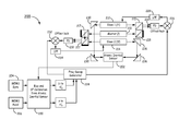
- FIG. 2 is a block diagram of an apparatus 200 for inertial sensing that provides closed loop control of an atomic inertial sensor according to one embodiment.
- the apparatus 200 generally includes at least one atomic inertial sensor 202 , and a plurality of micro electrical-mechanical systems (MEMS) inertial sensors, such as a MEMS gyroscope 204 and a MEMS accelerometer 206 .
- MEMS micro electrical-mechanical systems
- the atomic inertial sensor 202 and the MEMS inertial sensors operatively communicate with each other in a closed feedback loop.
- the apparatus 200 also includes a plurality of laser devices, including a master laser 210 , a first slave laser 212 , and a second slave laser 214 , which are in optical communication with atomic inertial sensor 202 .
- the master laser 210 is locked to a saturated absorption frequency (f) or an etalon (not shown).
- the first slave laser 212 has a first shifted frequency (f 1 )
- the second slave laser 214 has a second shifted frequency (f 2 ).
- the laser devices can be distributed Bragg reflector (DBR) laser diodes.
- the laser devices include a vertical-cavity surface-emitting laser (VCSEL).
- a beam from master laser 210 and a beam from slave laser 212 are directed by one or more optical components 215 such that the beams interfere with one another and generate a radio frequency (RF) signal at a first photodetector 216 such as a photodiode (PD).
- a first photodetector 216 such as a photodiode (PD).
- the beam from master laser 210 and a beam from slave laser 214 are directed by one or more optical components 217 such that the beams interfere with one another and generate an RF signal at a second photodetector 218 .
- the atomic inertial sensor 202 which exploits fundamental atomic physics to minimize drift, sequentially measures motion with respect to all three coordinate axes by selecting laser beam pairs that are oriented orthogonal (rotation) and parallel (acceleration) to those axes. Further details of an exemplary embodiment of the atomic inertial sensor can be found in U.S. application Ser. No. 13/661,809, entitled MULTI-AXIS ATOMIC INERTIAL SENSOR SYSTEM, the disclosure of which is incorporated by reference.
- the MEMS gyroscope 204 and MEMS accelerometer 206 are operatively coupled to a calibration unit 220 , which corrects MEMS bias and scale factor (SF) errors based on comparison of atomic data from atomic inertial sensor 202 .
- the calibration unit 220 converts the rotation rate signal ( ⁇ ) received from gyroscope 204 into a first frequency offset ( ⁇ f ⁇ ), and converts the acceleration signal ( ⁇ ) received from accelerometer 206 into a second frequency offset ( ⁇ f ⁇ ).
- the first and second frequency offsets are sent to a frequency sweep generator 224 , which sends a frequency sweep signal to a first mixer 226 .
- the mixer 226 also receives the RF signal from photodetector 216 .
- the mixer 226 compares the frequency sweep signal to the RF signal and provides a frequency offset lock signal that is sent to a low pass filter (LPF) 228 .
- LPF low pass filter
- the filtered signal from LPF 228 is sent to slave laser 212 to adjust its frequency.
- the slave laser 212 emits a beam at the adjusted frequency that is directed to an input of atomic inertial sensor 202 by a pair of reflectors 230 .
- the sweep generator 224 also sends the frequency sweep signal to a second mixer 232 , which also receives the RF signal from photodetector 218 .
- the mixer 232 compares the frequency sweep signal to the RF signal from photodetector 218 and provides a frequency offset lock signal that is sent to an LPF 234 .
- the filtered signal from LPF 234 is sent to slave laser 214 to adjust its frequency.
- the slave laser 214 emits a beam at the adjusted frequency that is directed to an input of atomic inertial sensor 202 by a pair of reflectors 236 .
- the frequency offsets applied to the slave lasers 212 and 214 are used to null the atomic sensor.
- the high update rate of the MEMS sensors enables the feedback to the atomic sensor, despite the low update rate of the atomic sensor.
- FIG. 3 shows the interferometer trajectory in a closed loop atomic inertial sensor 300 according to another embodiment.
- the interferometer in atomic inertial sensor 300 is created by two counter-propagating laser beam pairs that intersect atoms and form a moving two-dimensional (2D) optical lattice that continuously sweeps to provide detuning. Relative detuning depends on location of the atoms.
- Two pairs of counter-propagating beams 310 a , 310 b and 320 a , 320 b intersect atoms in the atomic sensor, with relative laser frequency ( ⁇ f) dependent on atom location x, where x is zero (0) at the center of the trajectory.
- the atom cloud is split by a Bragg grating, sending the two clouds on diverging paths, moving left to right in the diagram of FIG. 3 and accumulating phase. The atom clouds are then recombined.
- the relative laser frequency ( ⁇ f) is the difference between the frequencies of the counter-propagating beams that perform interferometry in the atomic sensor. Detuning changes the sign. Detuning ( ⁇ f) depends on the x coordinate of the atom cloud and is defined by the following equation:
- Example 1 includes an apparatus for inertial sensing, the apparatus comprising at least one atomic inertial sensor, and one or more micro-electrical-mechanical systems (MEMS) inertial sensors operatively coupled to the atomic inertial sensor.
- MEMS micro-electrical-mechanical systems
- the atomic inertial sensor and the MEMS inertial sensors operatively communicate with each other in a closed feedback loop.
- Example 2 includes the apparatus of Example 1, wherein the atomic inertial sensor comprises an atomic interferometer.
- Example 3 includes the apparatus of any of Examples 1-2, wherein the MEMS inertial sensors comprise at least one MEMS gyroscope and at least one MEMS accelerometer.
- Example 4 includes the apparatus of any of Examples 1-3, further comprising a plurality of laser devices in optical communication with the atomic inertial sensor.
- Example 5 includes the apparatus of Example 4, wherein the laser devices comprise distributed Bragg reflector laser diodes or vertical-cavity surface-emitting lasers.
- Example 6 includes the apparatus of any of Examples 4-5, wherein the laser devices comprise a master laser that emits a first beam and a second beam, a first slave laser that emits a first beam and a second beam, and a second slave laser that emits a first beam and a second beam.
- the laser devices comprise a master laser that emits a first beam and a second beam, a first slave laser that emits a first beam and a second beam, and a second slave laser that emits a first beam and a second beam.
- Example 7 includes the apparatus of Example 6, further comprising one or more optical components that direct the first beam from the master laser and the first beam from the first slave laser to interfere with one another and generate a first radio frequency signal at a first photodetector.
- Example 8 includes the apparatus of any of Examples 6-7, further comprising one or more optical components that direct the second beam from the master laser and the first beam from the second slave laser to interfere with one another and generate a second radio frequency signal at a second photodetector.
- Example 9 includes the apparatus of any of Examples 3-8, wherein the MEMS gyroscope and the MEMS accelerometer are each operatively coupled to a calibration unit that corrects for MEMS bias and scale factor errors based on a comparison of atomic data from the atomic inertial sensor.
- Example 10 includes the apparatus of Example 9, wherein the calibration unit converts a rotation rate signal received from the MEMS gyroscope into a first frequency offset, and converts an acceleration signal received from the MEMS accelerometer into a second frequency offset.
- Example 11 includes the apparatus of Example 10, further comprising a frequency sweep generator that receives the first and second frequency offsets from the calibration unit.
- Example 12 includes the apparatus of Example 11, further comprising a first mixer that receives a first frequency sweep signal from the frequency sweep generator and receives the first radio frequency signal from the first photodetector, wherein the first mixer compares the first frequency sweep signal to the first radio frequency signal and generates a frequency offset lock signal that is sent to a first low pass filter.
- Example 13 includes the apparatus of Example 12, wherein the first low pass filter sends a filtered signal to the first slave laser to adjust its frequency such that the second beam emitted by the first slave laser is at an adjusted frequency and is directed to a first input of the atomic inertial sensor.
- Example 14 includes the apparatus of any of Examples 11-13, further comprising a second mixer that receives a second frequency sweep signal from the frequency sweep generator and receives the second radio frequency signal from the second photodetector, wherein the second mixer compares the second frequency sweep signal to the second radio frequency signal and generates a frequency offset lock signal that is sent to a second low pass filter.
- Example 15 includes the apparatus of Example 14, wherein the second low pass filter sends a filtered signal to the second slave laser to adjust its frequency such that the second beam emitted by the second slave laser is at an adjusted frequency and is directed to a second input of the atomic inertial sensor.
- Example 16 includes a method for inertial sensing that comprises providing an inertial sensing apparatus comprising at least one atomic inertial sensor, and a plurality of MEMS inertial sensors in operative communication with the atomic inertial sensor, the MEMS inertial sensors comprising at least one MEMS gyroscope and at least one MEMS accelerometer, wherein the atomic inertial sensor and the MEMS inertial sensors operatively communicate with each other in a closed feedback loop.
- the method further comprises directing a first beam from a master laser and a first beam from a first slave laser to interfere with one another and generate a first radio frequency signal; directing a second beam from the master laser and a first beam from a second slave laser to interfere with one another and generate a second radio frequency signal; converting a rotation rate signal received from the MEMS gyroscope into a first frequency offset; converting an acceleration signal received from the MEMS accelerometer into a second frequency offset; generating a frequency sweep signal from the first and second frequency offsets; comparing the frequency sweep signal to the first radio frequency signal to generate a first frequency offset lock signal; comparing the frequency sweep signal to the second radio frequency signal to generate a second frequency offset lock signal; sending the first frequency offset lock signal to the first slave laser to adjust its frequency such that the first slave laser emits a second beam at an adjusted frequency that is directed to the atomic inertial sensor; and sending the second frequency offset lock signal to the second slave laser to adjust its frequency such that the second slave laser emits a second beam at an
- Example 17 includes the method of Example 16, wherein the atomic inertial sensor comprises an atomic interferometer.
- Example 18 includes the method of any of Examples 16-17, further comprising correcting outputs of the MEMS gyroscope and MEMS accelerometer for MEMS bias and scale factor errors based on a comparison of atomic data from the atomic inertial sensor.
- Example 19 includes an inertial sensing apparatus that comprises at least one atomic inertial sensor comprising an atomic interferometer, a plurality of MEMS inertial sensors in operative communication with the atomic inertial sensor, the MEMS inertial sensors comprising at least one MEMS gyroscope and at least one MEMS accelerometer, and a plurality of laser devices in optical communication with the atomic inertial sensor.
- the atomic inertial sensor and the MEMS inertial sensors operatively communicate with each other in a closed feedback loop.
- Example 20 includes the apparatus of Example 19, further comprising a calibration unit operatively coupled to the MEMS gyroscope and the MEMS accelerometer, the calibration unit configured to correct for MEMS bias and scale factor errors based on a comparison of atomic data from the atomic inertial sensor.
Abstract
Description
where:
- |ce|2 is the probability of finding the atom in the excited state after recombination;
- δ is the effective detuning of the laser light relative to the atomic transition;
- τ is the duration of an optical π pulse; and
Δφ=φ1−2φ2+φ3
where the φi are the phases of the laser relative to the atoms for each pulse. (See Young et al., Precision Atom Interferometry with Light Pulses, Atom Interferometry, P. Berman ed., Academic Press, San Diego, 1997).
where:
- Ω is rotation rate measured by the MEMS gyroscope;
- ν is velocity measured by the MEMS accelerometer;
- c is velocity of light;
- f is average frequency=(f1+f2)/2=c/λeff; and
- λeff is average wavelength of light.
Example Embodiments
Claims (19)
Priority Applications (4)
| Application Number | Priority Date | Filing Date | Title |
|---|---|---|---|
| US13/758,370 US9030655B2 (en) | 2012-06-27 | 2013-02-04 | Closed loop atomic inertial sensor |
| EP13171764.7A EP2679953B1 (en) | 2012-06-27 | 2013-06-12 | Closed loop atomic inertial sensor |
| JP2013126602A JP2014029325A (en) | 2012-06-27 | 2013-06-17 | Closed loop atomic inertial sensor |
| CN201310258666.2A CN103512568A (en) | 2012-06-27 | 2013-06-26 | Closed loop atomic inertial sensor |
Applications Claiming Priority (2)
| Application Number | Priority Date | Filing Date | Title |
|---|---|---|---|
| US201261665061P | 2012-06-27 | 2012-06-27 | |
| US13/758,370 US9030655B2 (en) | 2012-06-27 | 2013-02-04 | Closed loop atomic inertial sensor |
Publications (2)
| Publication Number | Publication Date |
|---|---|
| US20140022534A1 US20140022534A1 (en) | 2014-01-23 |
| US9030655B2 true US9030655B2 (en) | 2015-05-12 |
Family
ID=48651888
Family Applications (1)
| Application Number | Title | Priority Date | Filing Date |
|---|---|---|---|
| US13/758,370 Active US9030655B2 (en) | 2012-06-27 | 2013-02-04 | Closed loop atomic inertial sensor |
Country Status (4)
| Country | Link |
|---|---|
| US (1) | US9030655B2 (en) |
| EP (1) | EP2679953B1 (en) |
| JP (1) | JP2014029325A (en) |
| CN (1) | CN103512568A (en) |
Cited By (8)
| Publication number | Priority date | Publication date | Assignee | Title |
|---|---|---|---|---|
| US20130218504A1 (en) * | 2012-02-17 | 2013-08-22 | Honeywell International Inc. | Estimation of conventional inertial sensor errors with atomic inertial sensor |
| US20160334441A1 (en) * | 2015-05-15 | 2016-11-17 | Honeywell International Inc. | In-situ bias correction for mems accelerometers |
| US20170370840A1 (en) * | 2016-06-22 | 2017-12-28 | The Charles Stark Draper Laboratory, Inc. | Separated Parallel Beam Generation for Atom Interferometry |
| US9983225B2 (en) | 2015-06-29 | 2018-05-29 | Honeywell International Inc. | Optical-mechanical vibrating beam accelerometer |
| US10330697B2 (en) | 2015-05-15 | 2019-06-25 | Honeywell International Inc. | Active, in-situ, calibration of MEMS accelerometers using optical forces |
| US10352702B2 (en) | 2016-09-02 | 2019-07-16 | Honeywell International Inc. | Fully reciprocal atomic interferometric gyroscope |
| WO2019241544A1 (en) * | 2018-06-15 | 2019-12-19 | Sri International | Atom chip for ultracold atom preparation and loading into an integrated optical waveguide evanescent field trap |
| WO2020142140A1 (en) | 2019-01-02 | 2020-07-09 | Kutztown University Of Pennsylvania | Rotation sensing and magnetometry using localization on a ring shaped lattice |
Families Citing this family (18)
| Publication number | Priority date | Publication date | Assignee | Title |
|---|---|---|---|---|
| US8941053B1 (en) * | 2011-09-28 | 2015-01-27 | Sandia Corporation | High data-rate atom interferometers through high recapture efficiency |
| US8860933B2 (en) * | 2012-07-12 | 2014-10-14 | Honeywell International Inc. | Multi-axis atomic inertial sensor system |
| US9291508B1 (en) * | 2013-03-13 | 2016-03-22 | Sandia Corporation | Light-pulse atom interferometric device |
| WO2014145233A1 (en) * | 2013-03-15 | 2014-09-18 | Johnson David M S | Ring architecture for sequential operation of an atomic gyroscope |
| US9618362B2 (en) * | 2014-06-03 | 2017-04-11 | Northrop Grumman Systems Corporation | Self-calibrating nuclear magnetic resonance (NMR) gyroscope system |
| US9175960B1 (en) | 2014-09-10 | 2015-11-03 | Honeywell International Inc. | Optically dithered atomic gyro-compass |
| FR3031187B1 (en) * | 2014-12-30 | 2017-10-20 | Thales Sa | COLD ATOMIC HYBRID INERTIA SENSOR AND MEMS AND ASSOCIATED INERTIAL PLANT |
| FR3044398B1 (en) * | 2015-11-27 | 2019-07-19 | Thales | LASER SOURCE FOR COLD ATOMIC INERTIAL SENSOR |
| US9887019B2 (en) * | 2016-02-04 | 2018-02-06 | Honeywell International Inc. | Systems and methods for eliminating multi-path errors from atomic inertial sensors |
| US10157692B2 (en) | 2016-06-22 | 2018-12-18 | The Charles Stark Draper Laboratory, Inc. | Cold atom interferometry |
| WO2018017898A1 (en) * | 2016-07-20 | 2018-01-25 | Urban626, Llc | Convertible scooter |
| CN106525019B (en) * | 2016-11-24 | 2023-07-25 | 华中科技大学 | Dual internal state Bragg atom interference inertial sensor |
| US11150093B1 (en) | 2017-01-25 | 2021-10-19 | AOSense, Inc. | Inertial navigation system design for precision mobile reference platforms |
| US10816569B2 (en) | 2018-09-07 | 2020-10-27 | Analog Devices, Inc. | Z axis accelerometer using variable vertical gaps |
| US11255873B2 (en) | 2018-09-12 | 2022-02-22 | Analog Devices, Inc. | Increased sensitivity z-axis accelerometer |
| US11133117B2 (en) * | 2019-05-08 | 2021-09-28 | Northrop Grumman Systems Corporation | Atomic interferometer system |
| EP3983829A1 (en) * | 2019-06-13 | 2022-04-20 | The University of Nottingham | Quantum gravimeters and gradiometers |
| FR3123980B1 (en) * | 2021-06-10 | 2023-06-30 | Thales Sa | ATOMIC CHIP WITH TWO CONDUCTIVE STRIPS FOR INERTIAL SENSOR WITH ULTRAFID ATOM AND ASSOCIATED SENSOR |
Citations (25)
| Publication number | Priority date | Publication date | Assignee | Title |
|---|---|---|---|---|
| US3761721A (en) | 1972-07-06 | 1973-09-25 | Trw Inc | Matter wave interferometric apparatus |
| US4545242A (en) * | 1982-10-27 | 1985-10-08 | Schlumberger Technology Corporation | Method and apparatus for measuring the depth of a tool in a borehole |
| US4992656A (en) | 1987-10-26 | 1991-02-12 | Clauser John F | Rotation, acceleration, and gravity sensors using quantum-mechanical matter-wave interferometry with neutral atoms and molecules |
| US5052808A (en) | 1990-02-15 | 1991-10-01 | Litton Systems, Inc. | Method and apparatus for interferometric rotation sensor phase modulation, intensity demodulation, and control |
| EP0511119A1 (en) | 1991-04-26 | 1992-10-28 | Alcatel | Fibre optic vibration sensor and accelerometer using the same |
| US5274231A (en) | 1992-04-14 | 1993-12-28 | Board Of Trustees, Leland Stanford Jr. University | Method and apparatus for manipulating atoms, ions or molecules and for measuring physical quantities using stimulated Raman transitions |
| US6456939B1 (en) * | 2000-01-04 | 2002-09-24 | Mccall Hiram | Micro inertial measurement unit |
| US6606908B2 (en) | 2000-06-28 | 2003-08-19 | Astrium Gmbh | Inertial sensor for the mounting and checking of an inertial reference in a satellite |
| US6647352B1 (en) | 1998-06-05 | 2003-11-11 | Crossbow Technology | Dynamic attitude measurement method and apparatus |
| US6697736B2 (en) | 2002-02-06 | 2004-02-24 | American Gnc Corporation | Positioning and navigation method and system thereof |
| US20050125141A1 (en) | 2003-12-05 | 2005-06-09 | Honeywell International Inc. | System and method for using multiple aiding sensors in a deeply integrated navigation system |
| US20060249666A1 (en) | 2005-02-01 | 2006-11-09 | Kasevich Mark A | Kinematic sensors employing atom interferometer phases |
| US7142983B2 (en) | 2003-07-03 | 2006-11-28 | Northrop Grumman Corporation | Method for the processing of non-continuous atom interferometer intertial instrument measurements and continuous wide bandwidth instrument measurements with a gravity database |
| WO2007002327A1 (en) | 2005-06-22 | 2007-01-04 | Litton Systems, Inc. | Method for combining continuous and discontinuous inertial instrument measurements and inertial navigation system using the same |
| US20090242743A1 (en) | 2008-03-19 | 2009-10-01 | Ixsea | Guided coherent atom source and atomic interferometer |
| US20100064767A1 (en) | 2008-09-15 | 2010-03-18 | Lockheed Martin Corporation | Atom-Interferometric, Stepped Gravity Gradient Measuring System |
| US7728587B2 (en) | 2007-07-31 | 2010-06-01 | Northrop Grumman Guidance And Electronics Company, Inc. | Self-calibrating nuclear magnetic resonance gyro |
| US20100149541A1 (en) | 2008-12-17 | 2010-06-17 | Lockheed Martin Corporation | Performance of an Atom Interferometric Device through Complementary Filtering |
| US20100149025A1 (en) | 2007-10-09 | 2010-06-17 | Honeywell International Inc. | Gps receiver raim with slaved precision clock |
| US7995630B2 (en) * | 2008-04-01 | 2011-08-09 | Rakuljic George A | High performance tunable lasers utilizing optical phase-locked loops |
| US8459093B2 (en) | 2009-12-21 | 2013-06-11 | Stmicroelectronics S.R.L. | Microelectromechanical gyroscope with continuous self-test function |
| EP2629303A1 (en) | 2012-02-17 | 2013-08-21 | Honeywell International Inc. | Atom interferometer with adaptive launch direction and/or position |
| US20130270434A1 (en) * | 2012-04-11 | 2013-10-17 | Honeywell International Inc. | Measuring the populations in each hyperfine ground state of alkali atoms in a vapor cell while limiting the contribution of the background vapor |
| US8583371B1 (en) | 2010-12-23 | 2013-11-12 | Lockheed Martin Corporation | Autonomous gyro temperature calibration |
| US20140016118A1 (en) | 2012-07-12 | 2014-01-16 | Honeywell International Inc. | Multi-axis atomic inertial sensor system |
Family Cites Families (1)
| Publication number | Priority date | Publication date | Assignee | Title |
|---|---|---|---|---|
| FR2928725B1 (en) * | 2008-03-12 | 2010-04-09 | Centre Nat Rech Scient | COLD ATOMIC INTERFEROMETRIC SENSOR |
-
2013
- 2013-02-04 US US13/758,370 patent/US9030655B2/en active Active
- 2013-06-12 EP EP13171764.7A patent/EP2679953B1/en active Active
- 2013-06-17 JP JP2013126602A patent/JP2014029325A/en not_active Ceased
- 2013-06-26 CN CN201310258666.2A patent/CN103512568A/en active Pending
Patent Citations (28)
| Publication number | Priority date | Publication date | Assignee | Title |
|---|---|---|---|---|
| US3761721A (en) | 1972-07-06 | 1973-09-25 | Trw Inc | Matter wave interferometric apparatus |
| US4545242A (en) * | 1982-10-27 | 1985-10-08 | Schlumberger Technology Corporation | Method and apparatus for measuring the depth of a tool in a borehole |
| US4992656A (en) | 1987-10-26 | 1991-02-12 | Clauser John F | Rotation, acceleration, and gravity sensors using quantum-mechanical matter-wave interferometry with neutral atoms and molecules |
| US5052808A (en) | 1990-02-15 | 1991-10-01 | Litton Systems, Inc. | Method and apparatus for interferometric rotation sensor phase modulation, intensity demodulation, and control |
| EP0511119A1 (en) | 1991-04-26 | 1992-10-28 | Alcatel | Fibre optic vibration sensor and accelerometer using the same |
| US5274231A (en) | 1992-04-14 | 1993-12-28 | Board Of Trustees, Leland Stanford Jr. University | Method and apparatus for manipulating atoms, ions or molecules and for measuring physical quantities using stimulated Raman transitions |
| US6647352B1 (en) | 1998-06-05 | 2003-11-11 | Crossbow Technology | Dynamic attitude measurement method and apparatus |
| US6456939B1 (en) * | 2000-01-04 | 2002-09-24 | Mccall Hiram | Micro inertial measurement unit |
| US6606908B2 (en) | 2000-06-28 | 2003-08-19 | Astrium Gmbh | Inertial sensor for the mounting and checking of an inertial reference in a satellite |
| US6697736B2 (en) | 2002-02-06 | 2004-02-24 | American Gnc Corporation | Positioning and navigation method and system thereof |
| US7142983B2 (en) | 2003-07-03 | 2006-11-28 | Northrop Grumman Corporation | Method for the processing of non-continuous atom interferometer intertial instrument measurements and continuous wide bandwidth instrument measurements with a gravity database |
| US20050125141A1 (en) | 2003-12-05 | 2005-06-09 | Honeywell International Inc. | System and method for using multiple aiding sensors in a deeply integrated navigation system |
| US20060249666A1 (en) | 2005-02-01 | 2006-11-09 | Kasevich Mark A | Kinematic sensors employing atom interferometer phases |
| WO2007002327A1 (en) | 2005-06-22 | 2007-01-04 | Litton Systems, Inc. | Method for combining continuous and discontinuous inertial instrument measurements and inertial navigation system using the same |
| US7728587B2 (en) | 2007-07-31 | 2010-06-01 | Northrop Grumman Guidance And Electronics Company, Inc. | Self-calibrating nuclear magnetic resonance gyro |
| US20100149025A1 (en) | 2007-10-09 | 2010-06-17 | Honeywell International Inc. | Gps receiver raim with slaved precision clock |
| US20090242743A1 (en) | 2008-03-19 | 2009-10-01 | Ixsea | Guided coherent atom source and atomic interferometer |
| US7995630B2 (en) * | 2008-04-01 | 2011-08-09 | Rakuljic George A | High performance tunable lasers utilizing optical phase-locked loops |
| US20100064767A1 (en) | 2008-09-15 | 2010-03-18 | Lockheed Martin Corporation | Atom-Interferometric, Stepped Gravity Gradient Measuring System |
| US20100149541A1 (en) | 2008-12-17 | 2010-06-17 | Lockheed Martin Corporation | Performance of an Atom Interferometric Device through Complementary Filtering |
| US7847924B2 (en) | 2008-12-17 | 2010-12-07 | Lockheed Martin Corporation | Performance of an atom interferometric device through complementary filtering |
| US8459093B2 (en) | 2009-12-21 | 2013-06-11 | Stmicroelectronics S.R.L. | Microelectromechanical gyroscope with continuous self-test function |
| US8583371B1 (en) | 2010-12-23 | 2013-11-12 | Lockheed Martin Corporation | Autonomous gyro temperature calibration |
| EP2629303A1 (en) | 2012-02-17 | 2013-08-21 | Honeywell International Inc. | Atom interferometer with adaptive launch direction and/or position |
| US20130213135A1 (en) | 2012-02-17 | 2013-08-22 | Honeywell International Inc. | Atom interferometer with adaptive launch direction and/or position |
| US20130270434A1 (en) * | 2012-04-11 | 2013-10-17 | Honeywell International Inc. | Measuring the populations in each hyperfine ground state of alkali atoms in a vapor cell while limiting the contribution of the background vapor |
| US20140016118A1 (en) | 2012-07-12 | 2014-01-16 | Honeywell International Inc. | Multi-axis atomic inertial sensor system |
| US8860933B2 (en) | 2012-07-12 | 2014-10-14 | Honeywell International Inc. | Multi-axis atomic inertial sensor system |
Non-Patent Citations (14)
| Title |
|---|
| "Ground State Laser cooling of trapped atoms using electromagnetically induced transparency" to J. Eschner et al., Laser Spectroscopy XV, World Scientific, Proceedings of the XV International Conference Snowbird, Utah, USA, Jun. 10-15, 2001-(pp. 325-328); retrievable from http://heart-c704.uibk.ac.at/publications/papers/icols01-eit-eschner.pdf. * |
| "Ground State Laser cooling of trapped atoms using electromagnetically induced transparency" to J. Eschner et al., Laser Spectroscopy XV, World Scientific, Proceedings of the XV International Conference Snowbird, Utah, USA, Jun. 10-15, 2001—(pp. 325-328); retrievable from http://heart-c704.uibk.ac.at/publications/papers/icols01—eit—eschner.pdf. * |
| , "Multi-Axis Atomic Inertial Sensor System", "U.S. Appl. No. 13/661,809 filed on Oct. 26, 2012", , pp. 1-20. |
| European Patent Office, "European Search Report", "from Foreign Counterpart of U.S. Appl. No. 13/758,309", May 31, 2013, pp. 1-5, Published in: EP. |
| European Patent Office, "European Search Report", "from Foreign Counterpart of U.S. Appl. No. 13/758,370", Nov. 8, 2013, pp. 1-3, Published in: EP. |
| European Patent Office, "Office Action from EP Application No. 13171764.7 mailed Dec. 17, 2013", "from Foreign Counterpart of U.S. Appl. No. 13/758,370", Dec. 17, 2013, pp. 1-7, Published in: EP. |
| European Patent Office, "Office Action", "from Foreign Counterpart of U.S. Appl. No. 13/758,309", Jul. 9, 2013, pp. 1-5, Published in: EP. |
| Geiger et al., "Detecting inertial effects with airborne matter-wave interferometry", "Nature Communications", Sep. 20, 2011, pp. 1-7. |
| https://jila.colorado.edu/research/atomic-molecular-physics/ultracold-atoms (Jul. 7, 2014). * |
| Peters et al., "High-Precision Gravity Measurements Using Atom interferometry", "Metrologia", Jun. 2001, pp. 25-61, vol. 38. |
| Schmidt et al., "A Mobile High-Presicion Absolute Gravimeter Based on Atom Interferometry", "Gyroscopy and Navigation", Apr. 21, 2011, vol. 2, No. 3. |
| U.S. Patent and Trademark Office, "Notice of Allowance and Fee(s) Due", U.S. Appl. No. 13/661,809, Aug. 18, 2014, pp. 1-19. |
| Wu, "Gravity Gradient Survey with a Mobile Atom Interferometer", Mar. 2009, pp. 1-160, Publisher: Xinan Wu. |
| Young et al., "Precision Atom Interferometry with Ligth Pulses", "at least as early as Dec. 1997", 1997, pp. 1-5, Publisher: Academic Press. |
Cited By (13)
| Publication number | Priority date | Publication date | Assignee | Title |
|---|---|---|---|---|
| US9423272B2 (en) * | 2012-02-17 | 2016-08-23 | Honeywell International Inc. | Estimation of conventional inertial sensor errors with atomic inertial sensor |
| US20130218504A1 (en) * | 2012-02-17 | 2013-08-22 | Honeywell International Inc. | Estimation of conventional inertial sensor errors with atomic inertial sensor |
| US20160334441A1 (en) * | 2015-05-15 | 2016-11-17 | Honeywell International Inc. | In-situ bias correction for mems accelerometers |
| US9874581B2 (en) * | 2015-05-15 | 2018-01-23 | Honeywell International Inc. | In-situ bias correction for MEMS accelerometers |
| US10330697B2 (en) | 2015-05-15 | 2019-06-25 | Honeywell International Inc. | Active, in-situ, calibration of MEMS accelerometers using optical forces |
| US9983225B2 (en) | 2015-06-29 | 2018-05-29 | Honeywell International Inc. | Optical-mechanical vibrating beam accelerometer |
| US20170370840A1 (en) * | 2016-06-22 | 2017-12-28 | The Charles Stark Draper Laboratory, Inc. | Separated Parallel Beam Generation for Atom Interferometry |
| US9952154B2 (en) * | 2016-06-22 | 2018-04-24 | The Charles Stark Draper Laboratory, Inc. | Separated parallel beam generation for atom interferometry |
| US10352702B2 (en) | 2016-09-02 | 2019-07-16 | Honeywell International Inc. | Fully reciprocal atomic interferometric gyroscope |
| WO2019241544A1 (en) * | 2018-06-15 | 2019-12-19 | Sri International | Atom chip for ultracold atom preparation and loading into an integrated optical waveguide evanescent field trap |
| US11549811B2 (en) | 2018-06-15 | 2023-01-10 | Sri International | Atom chip for ultracold atom preparation and loading into an integrated optical waveguide evanescent field trip |
| WO2020142140A1 (en) | 2019-01-02 | 2020-07-09 | Kutztown University Of Pennsylvania | Rotation sensing and magnetometry using localization on a ring shaped lattice |
| US11243079B2 (en) | 2019-01-02 | 2022-02-08 | Kutztown University Of Pennsylvania | Rotation sensing and magnetometry using localization on a ring shaped lattice |
Also Published As
| Publication number | Publication date |
|---|---|
| JP2014029325A (en) | 2014-02-13 |
| EP2679953B1 (en) | 2020-03-04 |
| CN103512568A (en) | 2014-01-15 |
| EP2679953A1 (en) | 2014-01-01 |
| US20140022534A1 (en) | 2014-01-23 |
Similar Documents
| Publication | Publication Date | Title |
|---|---|---|
| US9030655B2 (en) | Closed loop atomic inertial sensor | |
| US11175139B2 (en) | Hybrid inertial measurement system and method using a light pulse cold atom interferometer | |
| EP3333543B1 (en) | Multi-axis atomic inertial sensor system | |
| JP5798639B2 (en) | Atomic beam gyroscope | |
| US9291508B1 (en) | Light-pulse atom interferometric device | |
| US9952154B2 (en) | Separated parallel beam generation for atom interferometry | |
| US10079467B2 (en) | Optomechanical laser for dynamic measurement | |
| US20160320173A1 (en) | Method of measuring a change in an optical path length using differential laser self-mixing interferometry and a differential laser self-mixing interferometry measuring system | |
| EP3752792B1 (en) | Velocity selective thermal atomic beam inertial sensor | |
| US20140368832A1 (en) | Interferometric determination of distance change with laser diode, high bandwidth detection and fast signal processing | |
| EP3034463B1 (en) | Coherent spectroscopic methods with extended interrogation times and systems implementing such | |
| Canuel et al. | The matter-wave laser interferometer gravitation antenna (MIGA): New perspectives for fundamental physics and geosciences | |
| US9897448B2 (en) | Systems and methods for multiple species atom interferometry | |
| EP2282243B1 (en) | Atomic clock system and frequency tuning method for such a system | |
| US11940276B2 (en) | Inertial point-source matter-wave atom interferometer gyroscope and extracting inertial parameters | |
| CN106525019B (en) | Dual internal state Bragg atom interference inertial sensor | |
| Bernard et al. | Progress towards the development of a cold-atom inertial measurement unit for onboard applications | |
| Ortolan et al. | GINGER: An array of ring lasers for testing fundamental physics | |
| US10386187B1 (en) | Rotation and acceleration sensor based on nondegenerate ring lasers | |
| WO2023055566A1 (en) | Phase-space filtering in thermal beam inertial sensors | |
| Annovazzi-Lodi et al. | Optical detection of multiple modes on resonant micromachined structures | |
| Hamilton et al. | Concept of a miniature atomic sensor |
Legal Events
| Date | Code | Title | Description |
|---|---|---|---|
| AS | Assignment |
Owner name: HONEYWELL INTERNATIONAL INC., NEW JERSEY Free format text: ASSIGNMENT OF ASSIGNORS INTEREST;ASSIGNORS:STRABLEY, JENNIFER S.;SALIT, KENNETH;SALIT, MARY K.;AND OTHERS;SIGNING DATES FROM 20130124 TO 20130204;REEL/FRAME:029748/0824 |
|
| STCF | Information on status: patent grant |
Free format text: PATENTED CASE |
|
| MAFP | Maintenance fee payment |
Free format text: PAYMENT OF MAINTENANCE FEE, 4TH YEAR, LARGE ENTITY (ORIGINAL EVENT CODE: M1551); ENTITY STATUS OF PATENT OWNER: LARGE ENTITY Year of fee payment: 4 |
|
| MAFP | Maintenance fee payment |
Free format text: PAYMENT OF MAINTENANCE FEE, 8TH YEAR, LARGE ENTITY (ORIGINAL EVENT CODE: M1552); ENTITY STATUS OF PATENT OWNER: LARGE ENTITY Year of fee payment: 8 |