US9034063B2 - Method of manufacturing grooved chemical mechanical polishing layers - Google Patents
Method of manufacturing grooved chemical mechanical polishing layers Download PDFInfo
- Publication number
- US9034063B2 US9034063B2 US13/628,364 US201213628364A US9034063B2 US 9034063 B2 US9034063 B2 US 9034063B2 US 201213628364 A US201213628364 A US 201213628364A US 9034063 B2 US9034063 B2 US 9034063B2
- Authority
- US
- United States
- Prior art keywords
- mold cavity
- axis
- polishing
- doughnut
- nozzle opening
- Prior art date
- Legal status (The legal status is an assumption and is not a legal conclusion. Google has not performed a legal analysis and makes no representation as to the accuracy of the status listed.)
- Active, expires
Links
Images


Classifications
-
- B—PERFORMING OPERATIONS; TRANSPORTING
- B24—GRINDING; POLISHING
- B24B—MACHINES, DEVICES, OR PROCESSES FOR GRINDING OR POLISHING; DRESSING OR CONDITIONING OF ABRADING SURFACES; FEEDING OF GRINDING, POLISHING, OR LAPPING AGENTS
- B24B37/00—Lapping machines or devices; Accessories
- B24B37/11—Lapping tools
- B24B37/20—Lapping pads for working plane surfaces
- B24B37/26—Lapping pads for working plane surfaces characterised by the shape of the lapping pad surface, e.g. grooved
-
- B—PERFORMING OPERATIONS; TRANSPORTING
- B24—GRINDING; POLISHING
- B24D—TOOLS FOR GRINDING, BUFFING OR SHARPENING
- B24D18/00—Manufacture of grinding tools or other grinding devices, e.g. wheels, not otherwise provided for
-
- B—PERFORMING OPERATIONS; TRANSPORTING
- B24—GRINDING; POLISHING
- B24D—TOOLS FOR GRINDING, BUFFING OR SHARPENING
- B24D18/00—Manufacture of grinding tools or other grinding devices, e.g. wheels, not otherwise provided for
- B24D18/0009—Manufacture of grinding tools or other grinding devices, e.g. wheels, not otherwise provided for using moulds or presses
-
- B—PERFORMING OPERATIONS; TRANSPORTING
- B24—GRINDING; POLISHING
- B24D—TOOLS FOR GRINDING, BUFFING OR SHARPENING
- B24D7/00—Bonded abrasive wheels, or wheels with inserted abrasive blocks, designed for acting otherwise than only by their periphery, e.g. by the front face; Bushings or mountings therefor
-
- H—ELECTRICITY
- H01—ELECTRIC ELEMENTS
- H01L—SEMICONDUCTOR DEVICES NOT COVERED BY CLASS H10
- H01L21/00—Processes or apparatus adapted for the manufacture or treatment of semiconductor or solid state devices or of parts thereof
- H01L21/02—Manufacture or treatment of semiconductor devices or of parts thereof
- H01L21/04—Manufacture or treatment of semiconductor devices or of parts thereof the devices having at least one potential-jump barrier or surface barrier, e.g. PN junction, depletion layer or carrier concentration layer
- H01L21/18—Manufacture or treatment of semiconductor devices or of parts thereof the devices having at least one potential-jump barrier or surface barrier, e.g. PN junction, depletion layer or carrier concentration layer the devices having semiconductor bodies comprising elements of Group IV of the Periodic System or AIIIBV compounds with or without impurities, e.g. doping materials
- H01L21/30—Treatment of semiconductor bodies using processes or apparatus not provided for in groups H01L21/20 - H01L21/26
- H01L21/302—Treatment of semiconductor bodies using processes or apparatus not provided for in groups H01L21/20 - H01L21/26 to change their surface-physical characteristics or shape, e.g. etching, polishing, cutting
- H01L21/304—Mechanical treatment, e.g. grinding, polishing, cutting
Definitions
- the present invention relates generally to the field of manufacture of polishing layers.
- the present invention is directed to a method of manufacturing grooved polishing layers for use in chemical mechanical polishing pads.
- PVD physical vapor deposition
- CVD chemical vapor deposition
- PECVD plasma-enhanced chemical vapor deposition
- ECP electrochemical plating
- Planarization is useful in removing undesired surface topography and surface defects, such as rough surfaces, agglomerated materials, crystal lattice damage, scratches, and contaminated layers or materials.
- Chemical mechanical planarization or chemical mechanical polishing (CMP) is a common technique used to planarize substrates, such as semiconductor wafers.
- CMP chemical mechanical planarization
- a wafer is mounted on a carrier assembly and positioned in contact with a polishing pad in a CMP apparatus.
- the carrier assembly provides a controllable pressure to the wafer, pressing it against the polishing pad.
- the pad is moved (e.g., rotated) relative to the wafer by an external driving force.
- a chemical composition (“slurry”) or other polishing solution is provided between the wafer and the polishing pad.
- slurry chemical composition
- the wafer surface is polished and made planar by the chemical and mechanical action of the pad surface and slurry.
- Polishing layers used in chemical mechanical polishing pads typically have a polishing surface with one or more grooves. There are several reasons for incorporating grooves in the polishing surface of a chemical mechanical polishing pad, including: (A) to provide the necessary hydrodynamic state of the contact between the substrate being polished and the polishing pad—(if the polishing pad is either ungrooved or unperforated, a continuous layer of polishing medium can exist between the substrate and the polishing pad causing hydroplaning, which prevents uniform intimate contact between the polishing pad and the substrate and significantly reduces the substrate material removal rate); (B) to ensure that the polishing medium is uniformly distributed across the polishing surface of the polishing pad and that sufficient polishing medium reaches the center of the substrate—(this is especially important when polishing reactive metals such as copper, in which the chemical component of the polishing is as critical as the mechanical component; uniform polishing medium distribution across the substrate is required to achieve the same polishing rate at the center and edge of the substrate; however, the thickness of the polishing medium layer should not be so great as to prevent
- One particularly common groove pattern that is used for many polishing applications combines curved grooves with a plurality of linear grooves forming an XY pattern (e.g., a plurality of concentric, circular grooves with a plurality of linear grooves forming an XY pattern).
- Conventional techniques for preparing polishing pads with such groove combinations ; however, often result in the generation of stringer defects (see FIG. 9 ).
- stringer defects see FIG. 9
- polishing pads made from increasingly lower modulus polymers to provide for improved polishing defectivity performance.
- Reinhardt et al. U.S. Pat. No. 5,578,362 discloses an exemplary polishing layer known in the art.
- the polishing layer of Reinhardt comprises a polymeric matrix having microspheres dispersed throughout. Generally, the microspheres are blended and mixed with a liquid polymeric material and transferred to a mold for curing. Conventional wisdom in the art is to minimize perturbations imparted to the contents of the mold cavity during the transferring process. To accomplish this result, the location of the nozzle opening through which the curable material is added to the mold cavity is conventionally maintained centrally relative to the cross section of the mold cavity and as stationary as possible relative to the top surface of the curable material as it collects in the mold cavity.
- the location of the nozzle opening conventionally moves only in one dimension to maintain a set elevation above the top surface of the curable material in the mold cavity throughout the transferring process.
- the molded article is then sliced to form polishing layers using a skiver blade, periodically dressed with an abrasive stone.
- polishing layers formed in this manner may exhibit unwanted defects (e.g., density defects and uneven, scored surfaces).
- Density defects are manifested as variations in the bulk density of the polishing layer material. In other words, areas having a lower filler concentration (e.g., microspheres in the Reinhardt polishing layers). Density defects are undesirable because it is believed that they may cause unpredictable, and perhaps detrimental, polishing performance variations from one polishing layer to the next and within a single polishing layer over its useful lifetime.
- polishing layers that exhibit ultra flat polishing surfaces is becoming increasingly desirable.
- the present invention provides a method of manufacturing a polishing layer with a grooved polishing surface for use in a chemical mechanical polishing pad; wherein the method comprises: providing a polishing layer with an ungrooved polishing surface; first machining at least one curved groove into the ungrooved polishing surface; and, then machining a plurality of linear grooves in an XY grid pattern into the polishing surface to produce the polishing layer with a grooved polishing surface; wherein the plurality of linear grooves are machined by a step down process, wherein a groove cutting tool makes multiple successive cutting passes to form each linear groove, and, wherein each successive cutting pass increases the depth of the linear groove being formed.
- the present invention provides a method of manufacturing a polishing layer with a grooved polishing surface for use in a chemical mechanical polishing pad; wherein the method comprises: providing a polishing layer with an ungrooved polishing surface by: providing a mold, having a mold base and a surrounding wall attached to the mold base; providing a liner with a top surface, a bottom surface and an average thickness of 2 to 10 cm; providing an adhesive; providing a curable material comprising a liquid prepolymer; providing a nozzle, having a nozzle opening; providing a skiver blade with a cutting edge; providing a strop; providing a stropping compound; bonding the bottom surface of the liner to the mold base using the adhesive, wherein the top surface of the liner and the surrounding wall define a mold cavity; charging the curable material through the nozzle opening to the mold cavity during a charging period, CP; allowing the curable material in the mold cavity to cure into a cake; separating the surrounding wall from the mold base and the cake; applying the
- the present invention provides a method of manufacturing a polishing layer with a grooved polishing surface for use in a chemical mechanical polishing pad; wherein the method comprises: providing a polishing layer with an ungrooved polishing surface by: providing a mold, having a mold base and a surrounding wall attached to the mold base; providing a liner with a top surface, a bottom surface and an average thickness of 2 to 10 cm; providing an adhesive; providing a curable material comprising a liquid prepolymer and a plurality of microelements; providing a nozzle, having a nozzle opening; providing a skiver blade with a cutting edge; providing a strop; providing a stropping compound; bonding the bottom surface of the liner to the mold base using the adhesive, wherein the top surface of the liner and the surrounding wall define a mold cavity; wherein the top surface of the liner defines a horizontal internal boundary of the mold cavity, wherein the internal horizontal boundary of the mold is oriented along an x-y plane, wherein the mold cavity
- FIG. 1 is a depiction of a side elevation view of a mold.
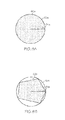
- FIG. 2 is a depiction of a perspective top/side view of a mold having a mold cavity with a substantially circular cross section.
- FIG. 3 is a depiction of a perspective top/side view of a mold having a mold cavity with a substantially circular cross section depicting a doughnut hole region and a doughnut region within the mold cavity.
- FIG. 4 is a depiction of a top plan view of the doughnut hole and doughnut region depicted in FIG. 3 .
- FIG. 5A is a depiction of a perspective top/side view of a mold cavity having a substantially circular cross section with a nozzle disposed within the mold cavity, wherein the mold cavity is partially filled with a curable material.
- FIG. 5B is a depiction of a side elevation view of the mold cavity depicted in FIG. 5A .
- FIG. 6A is a depiction of a perspective top/side view of a mold cavity having a substantially circular cross section with a doughnut hole region and a doughnut region and depicting multiple exemplary initial phase and transition phase paths.
- FIG. 6B is a depiction of a side elevation view of the mold cavity depicted in FIG. 6A .
- FIG. 6C is a depiction of a top plan view of the mold cavity depicted in FIG. 6A showing the projections onto the x-y plane of the initial phase and transition phase paths depicted in FIG. 6A .
- FIG. 7A is a depiction of a perspective top/side view of a mold cavity having a substantially circular cross section with a doughnut hole region and a doughnut region and depicting an exemplary remainder phase path.
- FIG. 7B is a depiction of a side elevation view of the mold cavity depicted in FIG. 7A .
- FIG. 7C is a depiction of a top plan view of the mold cavity depicted in FIG. 7A showing the projection onto the x-y plane of the remainder phase path depicted in FIG. 7A .
- FIG. 8A is a depiction of a plan view of a nozzle opening, wherein the nozzle opening is circular.
- FIG. 8B is a depiction of a plan view of a nozzle opening, wherein the nozzle opening is non-circular.
- FIG. 9 is a depiction of a top down view of a portion of a polishing surface of a polishing layer, 225 , with a stringer defect, 250 .
- polishing layer has a polishing surface with at least one curved groove and a plurality of linear grooves forming an XY pattern; that machining linear grooves into a polishing surface with at least one previously machined curved groove using a step down process (wherein a groove cutting tool makes multiple successive cutting passes to form each linear groove, wherein each successive cutting pass increases the depth of the linear groove being formed) results in a reduction in the formation of stringer defects when compared to polishing layers produced using the same process except that the plurality of linear grooves are machined using a single pass, full depth cutting technique.
- the preferred method of providing the polishing layers with an ungrooved polishing surface of the present invention involving movement of the location of the nozzle opening through which a curable material is charged into a mold cavity in three dimensions both along and about a central axis, C axis , of the mold cavity while charging the curable material into the mold cavity, significantly reduces the occurrence of density defects in the polishing layers produced relative to those produced by an identical process, wherein the location of the nozzle opening moves in only one dimension along the mold cavity's central axis, C axis .
- this preferred method of providing polishing layers with an ungrooved polishing surface of the method of the present invention results in an ungrooved polishing surface with a decreased surface roughness compared to polishing layers produced using the same process except that throughout the charging period, CP, the location of the nozzle opening moves in only one dimension along the mold cavity's central axis, C axis (i.e., to maintain the location of the nozzle opening at a set elevation above the top surface of the curable material as it collects in the mold cavity) and the skiver blade is stone sharpened rather than stropped before cake skiving.
- the cutting edge of the skiver blade becomes almost imperceptibly distorted and wavy after skiving a cake into a plurality of ungrooved polishing layers. It is believed that the prior art approach to sharpening the cutting edge with a stone results in the removal of material from the wavy portions of the cutting edge to provide a flat honed surface, but at the cost of varying tensile properties of the cutting edge across the length of the skiver blade; resulting in a non-uniformity in its cutting properties and an increased surface roughness in the ungrooved polishing layers produced therewith.
- surface roughness refers to the roughness of the polishing surface of an ungrooved polishing layer as determined using a profilometer, for example, a Zeiss Surfcom profilometer using the following parameter settings: measurement type—Gaussian; tilt—straight; tilt correction—least square; measurement length—0.6 inch (15.24 mm); cutoff wavelength—0.1 inch (2.54 mm); measurement speed—0.24 inch/s (6.1 mm/s); and, cutoff filter ratio—300.
- charging period or CP refers to the period of time (in seconds) over which curable material is charged into the mold cavity starting at the moment when the first of the curable material is introduced into the mold cavity until the moment when the last of the curable material is introduced into the mold cavity.
- charging rate or CR refers to the mass flow rate (in kg/sec) at which the curable material is charged to the mold cavity during the charging period, CP, (in seconds).
- initial phase starting point or SP IP refers to the location of the nozzle opening at the start of the initial phase of the charging period, which coincides with the start of the charging period.
- initial phase ending point or EP IP refers to the location of the nozzle opening at the end of the initial phase of the charging period, which immediately precedes the start of the transition phase of the charging period.
- initial phase path refers to the path of movement (if any) of the location of the nozzle opening during the initial phase of the charge period from the initial phase starting point, SP IP , to the initial phase ending point, EP IP .
- transition phase starting point or SP TP refers to the location of the nozzle opening at the start of the transition phase of the charging period.
- the transition phase starting point, SP TP , and the initial phase ending point, EP IP are at the same location.
- transition phase transition point(s) or TP TP refers to the location(s) of the nozzle opening during the transition phase of the charging period at which the direction of movement of the location of the nozzle opening relative to the mold cavity's central axis, C axis , changes (i.e., the direction of movement in the x and y dimensions).
- transition phase ending point or EP TP refers to the first location of the nozzle opening within the doughnut region of a mold cavity at which the direction of movement of the location of the nozzle opening relative to the mold cavity's central axis, C axis , changes.
- the transition phase ending point, EP TP is also the location of the nozzle opening at the end of the transition phase of the charging period, which immediately precedes the remainder phase of the charging period.
- transition phase path refers to the path taken by the location of the nozzle opening during the transition phase of the charging period from the transition phase starting point, SP TP , to the transition phase ending point, EP TP .
- remainder phase starting point or SP RP refers to the location of the nozzle opening at the start of the remainder phase of the charging period.
- SP RP transition phase ending point
- EP TP transition phase ending point
- TP RP residual phase transition points
- replenisher phase path refers to the path taken by the location of the nozzle opening during the remainder phase of the charging period from the remainder phase starting point, SP RP , to the remainder phase ending point, EP RP .
- poly(urethane) encompasses products derived from the reaction of difunctional or polyfunctional isocyanates (including isocyanate-terminated prepolymers) with compounds containing active—hydrogen groups, including but not limited to polyols, diols, amines, water or combinations thereof.
- reaction products include but are not limited to polyurethanes, polyureas, polyurethaneureas, poyetherurethanes, polyesterurethanes, polyetherureas, polyesterureas, polyisocyanurates, copolymers thereof and mixtures thereof.
- substantially non-porous as used herein and in the appended claims in reference to the liner, means that the liner contains ⁇ 5% porosity by volume.
- CR max ⁇ (1.1*CR avg ) CR min ⁇ (0.9*CR avg )
- CR max is the maximum mass flow rate (in kg/sec) at which the curable material is charged to the mold cavity during the charging period
- CR min is the minimum mass flow rate (in kg/sec) at which the curable material is charged to the mold cavity during the charging period
- CR avg the total mass (in kg) of curable material charged to the mold cavity over the charging period divided by the length of the charging period (in seconds).
- gel time as used herein and in the appended claims in reference to a curable material means the total cure time for that mixture as determined using a standard test method according to ASTM D3795-00a (Reapproved 2006)( Standard Test Method for Thermal Flow, Cure, and Behavior Properties of Pourable Thermosetting Materials by Torque Rheometer ).
- substantially circular as used herein and in the appended claims in reference to a groove means that the longest diameter of the groove is ⁇ 20% longer than the shortest diameter of the groove.
- substantially circular cross section as used herein and in the appended claims in reference to a mold cavity ( 20 ) means that the longest radius, r C , of the mold cavity ( 20 ) projected onto the x-y plane ( 30 ) from the mold cavity's central axis, C axis , ( 22 ) to a vertical internal boundary ( 18 ) of a surrounding wall ( 15 ) is ⁇ 20% longer than the shortest radius, r C , of the mold cavity ( 20 ) projected onto the x-y plane ( 30 ) from the mold cavity's central axis, C axis , ( 22 ) to the vertical internal boundary ( 18 ). (See FIG. 2 ).
- mold cavity refers to the volume defined by a horizontal internal boundary ( 14 ) corresponding to a top surface ( 6 , 12 ) of a liner ( 4 ) and a vertical internal boundary ( 18 ) of a surrounding wall ( 15 ). (See FIGS. 1-3 ).
- substantially coincides as used herein and in the appended claims in reference to an axis of symmetry of a curved groove in relation to an axis of symmetry of a polishing layer in the plane of the polishing surface, means that the axis of symmetry of the curved groove falls within a circular area in the plane of the polishing surface having the axis of symmetry of the polishing layer at the center and having a radius equal to 10% of the longest radius of the polishing layer in the plane of the polishing surface.
- first feature e.g., a horizontal internal boundary; a vertical internal boundary
- second feature e.g., an axis, an x-y plane
- first feature e.g., a horizontal internal boundary; a vertical internal boundary
- second feature e.g., an axis, an x-y plane
- Density defect refers to a region in a polishing layer having a significantly reduced filler concentration relative to the rest of the polishing layer. Density defects are visually detectable with the unaided human eye upon placing the polishing layer on a light table, wherein the density defects appear as regions having a markedly higher transparency compared with the rest of the polishing layer.
- FIG. 8A is a depiction of a plan view of a nozzle opening ( 62 a ) completely occluded by a smallest circle, SC, ( 63 a ) having a radius, r SC , ( 64 a ); wherein the nozzle opening is circular.
- FIG. 8A is a depiction of a plan view of a nozzle opening ( 62 a ) completely occluded by a smallest circle, SC, ( 63 a ) having a radius, r SC , ( 64 a ); wherein the nozzle opening is circular.
- 8B is a depiction of a plan view of a nozzle opening ( 62 b ) completely occluded by a smallest circle, SC, ( 63 b ) having a radius, r SC , ( 64 b ); wherein the nozzle opening is non-circular.
- r NO is 5 to 13 mm. More preferably r NO is 8 to 10 mm.
- the polishing layer with an ungrooved polishing surface used in the method of the present invention is preferably provided from a cake prepared using a mold ( 1 ) having a mold base ( 2 ) and a surrounding wall ( 8 ) attached to the mold base ( 2 ); wherein a liner ( 4 ) with a top surface ( 6 ), a bottom surface ( 3 ) and an average thickness ( 5 ), t L , is bonded to the mold base ( 2 ) using an adhesive ( 7 ) interposed between the bottom surface ( 3 ) of the liner ( 4 ) and the mold base ( 2 ). (See FIG. 1 ).
- the liner ( 4 ) facilitates the mating of a curable material as it reacts to form a solidified cake, wherein the curable material bonds to the liner ( 4 ) with sufficient strength so that the cured cake does not delaminate from the liner during skiving.
- the liner ( 4 ) used is periodically removed from the mold base ( 2 ) and replaced.
- the liner ( 4 ) used can be any material to which the curable material will bond upon curing.
- the liner ( 4 ) used is a polyurethane polymeric material.
- the liner ( 4 ) used is formed from a prepolymer reaction product of toluene diisocyanate and polytetramethylene ether glycol with an aromatic diamine curative.
- aromatic diamine curative is selected from 4,4′-methylene-bis-o-chloroaniline and 4,4′-methylene-bis-(3-chloro-2,6-diethylaniline).
- the prepolymer reaction product has a 6.5 to 15.0 weight percent unreacted NCO concentration.
- prepolymers having an unreacted NCO concentration of 6.5 to 15.0 wt % include, for example: Airthane® prepolymers PET-70D, PHP-70D, PET-75D, PHP-75D, PPT-75D, and PHP-80D manufactured by Air Products and Chemicals, Inc.; and, Adiprene® prepolymers, LFG740D, LF700D, LF750D, LF751D, LF753D, and L325 manufactured by Chemtura.
- the curative and the prepolymer reaction product are combined at a stoichiometric ratio of 85 to 125% (more preferably, 90 to 115 percent; most preferably, 95 to 105%) of NH 2 (or OH) in the curative to unreacted NCO in the prepolymer.
- This stoichiometry can be achieved either directly, by providing the stoichiometric levels of the raw materials, or indirectly by reacting some of the NCO with water either purposely or by exposure to adventitious moisture.
- the liner ( 4 ) used can be porous or non-porous. Preferably, the liner ( 4 ) used is substantially non-porous.
- the liner ( 4 ) used preferable exhibits an average thickness ( 5 ), t L , of 2 to 10 cm (more preferably 2 to 5 cm) measured using a granite base comparator (e.g., a Chicago Dial Indicator Cat #6066-10) at a plurality of randomly selected points (i.e., ⁇ 10 points) across the liner ( 4 ). (See FIG. 1 ).
- a granite base comparator e.g., a Chicago Dial Indicator Cat #6066-10
- the adhesive ( 7 ) used can be any adhesive suitable for bonding the liner ( 4 ) to the mold base ( 2 ).
- the adhesive ( 7 ) used can be selected from pressure sensitive adhesives, hot melt adhesives, contact adhesives and combinations thereof.
- the adhesive ( 7 ) used will both (a) bond the liner ( 4 ) to the mold base ( 2 ) with sufficient strength to prevent delamination of the liner ( 4 ) from the mold base ( 2 ) during the cake skiving operation; and, (b) be removable from the mold base ( 2 ) without physical damage to the mold base ( 2 ) or leaving a deleterious residue (i.e., a residue that impairs the obtainment of a functional bond between the mold base ( 2 ) and a replacement liner).
- the adhesive ( 7 ) is a pressure sensitive adhesive.
- the mold base ( 2 ) used can be any suitably rigid material that will support the weight of the curable material to be charged into the mold cavity; will facilitate the transfer of the filled mold between the equipment used for charging, curing (e.g., large ovens) and skiving the cured cake; and, can withstand the temperature swings associated with the process without warping.
- the mold base ( 2 ) used is made of stainless steel (more preferably 316 stainless steel).
- the top surface ( 12 ) of the liner used defines a horizontal internal boundary ( 14 ) of the mold cavity ( 20 ).
- the horizontal internal boundary ( 14 ) of the mold cavity ( 20 ) is flat. More preferably, the horizontal internal boundary ( 14 ) of the mold cavity ( 20 ) is flat and is substantially perpendicular to the mold cavity's central axis, C axis . Most preferably, the horizontal internal boundary ( 14 ) of the mold cavity ( 20 ) is flat and is essentially perpendicular to the mold cavity's central axis, C axis .
- the surrounding wall ( 15 ) of the mold ( 10 ) used defines a vertical internal boundary ( 18 ) of the mold cavity ( 20 ). (See, e.g., FIGS. 2-3 ).
- the surrounding wall defines a vertical internal boundary ( 18 ) of the mold cavity ( 20 ) that is substantially perpendicular to the x-y plane ( 30 ). More preferably, the surrounding wall defines an vertical internal boundary ( 18 ) of the mold cavity ( 20 ) that is essentially perpendicular to the x-y plane ( 30 ).
- the mold cavity ( 20 ) has a central axis, C axis , ( 22 ) that coincides with the z-axis and that intersects the horizontal internal boundary ( 14 ) of the mold cavity ( 20 ) at a center point ( 21 ).
- the center point ( 21 ) is located at the geometric center of the cross section, C x-sect , ( 24 ) of the mold cavity ( 20 ) projected onto the x-y plane ( 30 ). (See, e.g., FIGS. 2-4 ).
- the mold cavity's cross section, C x-sect , projected onto the x-y plan can be any regular or irregular two dimensional shape.
- the mold cavity's cross section, C x-sect is selected from a polygon and an ellipse. More preferably, the mold cavity's cross section, C x-sect , is a substantially circular cross section having an average radius, r C (preferably, wherein r C is 20 to 100 cm; more preferably, wherein r C is 25 to 65 cm; most preferably, wherein r C is 40 to 60 cm).
- the mold cavity ( 20 ) has a doughnut hole region ( 40 ) and a doughnut region ( 50 ). (See, e.g., FIGS. 3-4 ).
- the doughnut hole region ( 40 ) of the mold cavity ( 20 ) is a right cylindrically shaped region within the mold cavity ( 20 ) that projects a circular cross section, DH x-sect ( 44 ) onto the x-y plane ( 30 ) and that has a doughnut hole region axis of symmetry, DH axis , ( 42 ); wherein the DH axis coincides with the mold cavity's central axis, C axis , and the z-axis. (See, e.g., FIGS. 3-4 ).
- r DH is the radius ( 46 ) of the doughnut hole region's circular cross section, DH x-sect , ( 44 ).
- r DH ⁇ r NO (more preferably, wherein r DH is 5 to 25 mm; most preferably, wherein r DH 8 to 15 mm).
- the doughnut region ( 50 ) of the mold cavity ( 20 ) is a toroid shaped region within the mold cavity ( 20 ) that projects an annular cross section, D x-sect , ( 54 ) onto the x-y plane ( 30 ) and that has a doughnut region axis of symmetry, D axis , ( 52 ); wherein the D axis coincides with the mold cavity's central axis, C axis , and the z-axis. (See, e.g., FIGS. 3-4 ).
- r D ⁇ r DH and wherein r D is 5 to 25 mm.
- r D ⁇ r DH and wherein r D is 8 to 15 mm.
- r D ⁇ r DH Preferably, wherein r D ⁇ r DH ; wherein R D >r D ; and wherein R D ⁇ (K*r C ), wherein K is 0.01 to 0.2 (more preferably, wherein K is 0.014 to 0.1; most preferably, wherein K is 0.04 to 0.086). More preferably, wherein r D ⁇ r DH ; wherein R D >r D ; and wherein R D is 20 to 100 mm (more preferably, wherein R D is 20 to 80 mm; most preferably, wherein R D is 25 to 50 mm).
- the length of the charging period, CP in seconds can vary significantly.
- the length of the charging period, CP will depend on the size of the mold cavity, the average charging rate, CR avg , and the properties of the curable material (e.g., gel time).
- the charging period, CP is 60 to 900 seconds (more preferably 60 to 600 seconds, most preferably 120 to 360 seconds).
- the charging period, CP will be constrained by the gel time exhibited by the curable material.
- the charging period, CP will be less than or equal to the gel time exhibited by the curable material being charged to the mold cavity. More preferably, the charging period, CP, will be less than the gel time exhibited by the curable material.
- the charging rate, CR (in kg/sec) can vary over the course of the charging period, CP.
- the charging rate, CR can be intermittent. That is, the charging rate, CR, can momentarily drop to zero at one or more times over the course of the charging period.
- the curable material is charged to the mold cavity at an essentially constant rate over the charging period. More preferably, the curable material is charged to the mold cavity at an essentially constant rate over the charging period, CP, with an average charging rate, CR avg , of 0.015 to 2 kg/sec (more preferably 0.015 to 1 kg/sec; most preferably 0.08 to 0.4 kg/sec).
- the charging period, CP is broken down into three separate phases identified as an initial phase, a transition phase and a remainder phase.
- the start of the initial phase corresponds with the start of the charging period, CP.
- the end of the initial phase immediately precedes the start of the transition phase.
- the end of the transition phase immediately precedes the start of the remainder phase.
- the end of the remainder phase corresponds with the end of the charging period, CP.
- the nozzle moves or transforms (e.g., telescopes) during the charging period, CP, such that the location of the nozzle opening moves in all three dimensions.
- the nozzle ( 60 ) moves or transforms (e.g., telescopes) during the charging period, CP, such that the location of the nozzle opening ( 62 ) moves relative to the horizontal internal boundary ( 112 ) of the mold cavity ( 120 ) along the mold cavity's central axis, C axis , ( 122 ) during the charging period, CP, to maintain the location of the nozzle opening ( 62 ) above the top surface ( 72 ) of the curable material ( 70 ) as the curable material ( 70 ) collects in the mold cavity ( 120 ). (See FIGS. 5A-5B ).
- the location of the nozzle opening ( 62 ) moves relative to the horizontal internal boundary ( 112 ) of the mold cavity ( 120 ) along the mold cavity's central axis, C axis , ( 122 ) during the charging period, CP, to maintain the location of the nozzle opening ( 62 ) at an elevation ( 65 ) above the top surface ( 72 ) of the curable material ( 70 ) as the curable material ( 70 ) collects in the mold cavity ( 120 ); wherein the elevation is >0 to 30 mm (more preferably, >0 to 20 mm; most preferably, 5 to 10 mm). (See FIG. 5B ).
- the location of the nozzle opening can momentarily pause in its motion along the mold cavity's central axis, C axis , (i.e., its motion in the z dimension) during the charging period.
- the location of the nozzle opening momentarily pauses in its motion relative to the mold cavity's central axis, C axis , at each transition phase transition point, TP TP , (if any) and at each remainder phase transition point, TP RP (i.e., the location of the nozzle opening momentarily stops moving in the z dimension).
- the location of the nozzle opening resides within the doughnut hole region of the mold cavity throughout the initial phase of the charging period (i.e., for the duration of the initial phase).
- the initial phase is >0 to 90 seconds long (more preferably >0 to 60 seconds long; most preferably 5 to 30 seconds long).
- the location of the nozzle opening remains stationary from the start of the initial phase of the charging period until the top surface of curable material in the mold cavity begins to rise at which moment the transition phase begins; wherein the initial phase starting point, SP IP , ( 80 ) and the initial phase ending point, EP IP , ( 81 a ) (which point coincides with a transition phase starting point, SP TP , ( 82 a )) are the same location within the doughnut hole region ( 140 ) of the mold cavity ( 220 ) along the mold cavity's central axis, C axis , ( 222 ).
- the doughnut hole region ( 140 ) is a right circular cylinder; and wherein the doughnut hole's axis of symmetry, DH axis , ( 142 ) coincides with the mold cavity's central axis, C axis , ( 222 ) and the z-axis. (See FIGS. 6A-6C ).
- the location of the nozzle opening can move during the initial phase, wherein the initial phase starting point, SP IP , is different from the initial phase ending point, EP IP (i.e., SP IP ⁇ EP IP ).
- the initial phase is >0 to (CP-10.02) seconds long; wherein CP is the charge period in seconds.
- the location of the nozzle opening preferably moves within the doughnut hole region ( 140 ) of the mold cavity ( 220 ) along the mold cavity's central axis, C axis , ( 222 ) from an initial phase starting point, SP IP , ( 80 ) to an initial phase ending point, EP IP , ( 81 b ) (which point coincides with a transition phase starting point, SP TP , ( 82 b )) to maintain the location of the nozzle opening at an elevation above the top surface of the curable material as it collects in the mold cavity ( 220 ) throughout the initial phase of the charging period. (See FIGS. 6A-6C ).
- the location of the nozzle opening moves from a point within the doughnut hole region of the mold cavity to a point within the doughnut region during the transition phase of the charging period.
- the transition phase is 0.02 to 30 seconds long (more preferably, 0.2 to 5 seconds long; most preferably, 0.6 to 2 seconds long).
- the location of the nozzle opening moves relative to the mold cavity's central axis, C axis , during the transition phase at an average speed of 10 to 70 mm/sec (more preferably 15 to 35 mm/sec, most preferably 20 to 30 mm/sec).
- the location of the nozzle opening momentarily pauses in its motion relative to the mold cavity's central axis, C axis , (i.e., momentarily stops moving in the x and y dimensions) at each transition phase transition point, TP TP , (if any) and at the transition phase ending point, EP TP .
- the location of the nozzle opening moves at a constant speed relative to the mold cavity's central axis, C axis , during the transition phase from the transition phase starting point, SP TP , through any transition phase transition points, TP TP , to the transition phase ending point, EP TP .
- the location of the nozzle opening moves from the transition phase starting point, SP TP , through a plurality of transition phase transition points, TP TP , to the transition phase ending point, EP TP ; wherein the transition phase path projected onto the x-y plane approximates a curve (more preferably wherein the transition phase path approximates a spiral easement).
- the location of the nozzle opening moves directly from the transition phase starting point, SP TP , to the transition phase ending point, EP TP ; wherein the transition phase path projected onto the x-y plane is a straight line.
- FIGS. 6A-6C depict three different transition phase paths in a mold cavity ( 220 ) having a central axis, C axis , ( 222 ); a right cylindrically shaped doughnut hole region ( 140 ) with an axis of symmetry, DH axis , ( 142 ); and a toroid shaped doughnut region ( 150 ) with an axis of symmetry, D axis , ( 152 ); wherein the mold cavity's central axis, C axis , ( 222 ), the doughnut hole's axis of symmetry, DH axis , ( 142 ) and the doughnut's axis of symmetry, D axis , ( 152 ) each coincide with the z axis.
- a first transition phase path depicted in FIGS. 6A-6C begins at a transition phase starting point, SP TP , ( 82 a ) within a doughnut hole region ( 140 ) of a mold cavity ( 220 ) and proceeds directly to a transition phase ending point, EP TP , ( 89 ) within a doughnut region ( 150 ) of the mold cavity ( 220 ); wherein the transition phase path 83 a projects as a single straight line ( 84 ) onto the x-y plane ( 130 ).
- 6A-6C begins at a transition phase starting point, SP TP , ( 82 b ) within a doughnut hole region ( 140 ) of a mold cavity ( 220 ) and proceeds directly to a transition phase ending point, EP TP , ( 89 ) within a doughnut region ( 150 ) of the mold cavity ( 220 ), wherein the transition phase path 83 b projects as a single straight line ( 84 ) onto the x-y plane ( 130 ).
- the location of the nozzle opening resides within the doughnut region during the remainder phase of the charging period (i.e., the location of the nozzle opening may pass through or reside in the doughnut hole region for some fraction of the remainder phase of the charging period).
- the location of the nozzle opening resides within the doughnut region throughout the remainder phase of the charging period (i.e., for the duration of the remainder phase).
- the remainder phase is ⁇ 10 seconds long. More preferably, the remainder phase is 10 to ⁇ (CP-0.2) seconds long; wherein CP is the charge period in seconds. Still more preferably, the remainder phase is 30 to ⁇ (CP-0.2) seconds long; wherein CP is the charge period in seconds.
- the remainder phase is 0.66*CP to ⁇ (CP-0.2) seconds long; wherein CP is the charge period in seconds.
- the location of the nozzle opening moves relative to the mold cavity's central axis, C axis , during the remainder phase at an average speed of 10 to 70 mm/sec (more preferably 15 to 35 mm/sec, most preferably 20 to 30 mm/sec).
- the location of the nozzle opening can momentarily pause in its motion relative to the mold cavity's central axis, C axis , at each remainder phase transition point, TP RP (i.e., the location of the nozzle opening can momentarily stop moving in the x and y dimensions).
- the location of the nozzle opening moves at a constant speed relative to the mold cavity's central axis, C axis , during the remainder phase from the remainder phase starting point, SP RP , through each of the remainder phase transition points, TP RP .
- the location of the nozzle opening moves from the remainder phase starting point, SP RP , through a plurality of remainder phase transition points, TP RP ; wherein the remainder phase path projects a series of connected lines onto the x-y plane.
- the remainder phase transition points, TP RP are all located within the doughnut region of the mold cavity.
- the series of connected lines projected onto the x-y plane by the remainder phase path approximates either a circle or a two dimensional spiral with a varying distance from the mold cavity's central axis, C axis .
- the series of connected lines projected onto the x-y plane by the remainder phase path approximates a two dimensional spiral, wherein successive remainder phase transition points, TP RP , project onto the x-y plane at either an increasing or a decreasing distance from the mold cavity's central axis, C axis .
- the series of connected lines projected onto the x-y plane by the remainder phase path approximates a circle, wherein successive remainder phase transition points, TP RP , project onto the x-y plane at an equal distance from the mold cavity's central axis, C axis , and wherein the series of connected lines projected onto the x-y plane by the remainder phase path is a regular polygon (i.e., equilateral and equiangular).
- the regular polygon has ⁇ 5 sides (more preferably ⁇ 8 sides; most preferably ⁇ 10 sides; preferably ⁇ 100 sides; more preferably ⁇ 50 sides; most preferably ⁇ 20 sides).
- the remainder phase path approximates a helix.
- the location of the nozzle opening continues moving along the mold cavity's central axis, C axis , to maintain the desired elevation above the top surface of the curable material collecting in the mold cavity while the location of the nozzle opening simultaneously traces a path that projects a regular polygon onto the x-y plane (preferably, wherein the regular polygon has 5 to 100 sides; more preferably, 5 to 50 sides; still more preferably, 8 to 25 sides; most preferably, 8 to 15 sides).
- FIGS. 7A-7C depict a portion of a preferred remainder phase path ( 95 ) that approximates a helix within the mold cavity ( 220 ) having a central axis, C axis , ( 222 ); a right cylindrically shaped doughnut hole region ( 140 ) with an axis of symmetry, DH axis , ( 142 ); and a toroid shaped doughnut region ( 150 ) with an axis of symmetry, D axis , ( 152 ); wherein the mold cavity's central axis, C axis , ( 222 ), the doughnut hole's axis of symmetry, DH axis , ( 142 ) and the doughnut's axis of symmetry, D axis , ( 152 ) each coincide with the z axis.
- the remainder phase path ( 95 ) begins at a remainder phase starting point, SP RP , ( 90 ) within the doughnut region ( 150 ) of the mold cavity ( 220 ) and proceeds through a plurality of remainder phase transition points, TP RP , ( 92 ) within a doughnut region ( 150 ) of the mold cavity ( 220 ); wherein all the remainder phase transition points, TP RP , are at an equal distance from the mold cavity's central axis, C axis , ( 222 ); and, wherein the remainder phase path 95 projects onto the x-y plane ( 130 ) as ten equal length lines ( 97 ) forming a regular decahedron ( 100 ).
- the remainder transition starting point, SP RP , ( 90 ) corresponds with the transition phase ending point, EP TP , ( 89 )(i.e., they are at the same location).
- the curable material preferably comprises a liquid prepolymer. More preferably, the curable material comprises a liquid prepolymer and a plurality of microelements, wherein the plurality of microelements are uniformly dispersed in the liquid prepolymer.
- the liquid prepolymer preferably polymerizes (i.e., cures) to form a material comprising a poly(urethane). More preferably, the liquid prepolymer polymerizes to form a material comprising a polyurethane. Most preferably, the liquid prepolymer polymerizes (cures) to form a polyurethane.
- the liquid prepolymer is a melt processable thermoplastic material.
- the melt processable thermoplastic material is selected from the group consisting of thermoplastic poly(urethane)(TPU), polysulfone, polyether sulfone, nylon, polyether, polyester, polystyrene, acrylic polymer, polyurea, polyamide, polyvinyl chloride, polyvinyl fluoride, polyethylene, polypropylene, polybutadiene, polyethylene imine, polyacrylonitrile, polyethylene oxide, polyolefin, poly(alkyl)acrylate, poly(alkyl)methacrylate, polyamide, polyether imide, polyketone, epoxy, silicone, polymer formed from ethylene propylene diene monomer, protein, polysaccharide, polyacetate and a combination of at least two of the foregoing.
- TPU thermoplastic poly(urethane)(TPU)
- TPU thermoplastic poly(urethane)(TPU)
- polysulfone polyether sulfone
- nylon polyether
- polyester polystyrene
- the liquid prepolymer comprises a polyisocyanate-containing material. More preferably, the liquid prepolymer comprises the reaction product of a polyisocyanate (e.g., diisocyanate) and a hydroxyl-containing material.
- a polyisocyanate e.g., diisocyanate
- the polyisocyanate is selected from methylene bis 4,4′-cyclohexyl-isocyanate; cyclohexyl diisocyanate; isophorone diisocyanate; hexamethylene diisocyanate; propylene-1,2-dissocyanate; tetramethylene-1,4-diisocyanate; 1,6-hexamethylene-diisocyanate; dodecane-1,12-diisocyanate; cyclobutane-1,3-diisocyanate; cyclohexane-1,3-diisocyanate; cyclohexane-1,4-diisocyanate; 1-isocyanato-3,3,5-trimethyl-5-isocyanatomethylcyclohexane; methyl cyclohexylene diisocyanate; triisocyanate of hexamethylene diisocyanate; triisocyanate of 2,4,4-trimethyl-1,6
- the hydroxyl-containing material used with the present invention is a polyol.
- exemplary polyols include, for example, polyether polyols, hydroxy-terminated polybutadiene (including partially and fully hydrogenated derivatives), polyester polyols, polycaprolactone polyols, polycarbonate polyols, and mixtures thereof.
- Preferred polyols include polyether polyols.
- polyether polyols include polytetramethylene ether glycol (“PTMEG”), polyethylene propylene glycol, polyoxypropylene glycol, and mixtures thereof.
- the hydrocarbon chain can have saturated or unsaturated bonds and substituted or unsubstituted aromatic and cyclic groups.
- the polyol of the present invention includes PTMEG.
- Suitable polyester polyols include, but are not limited to, polyethylene adipate glycol; polybutylene adipate glycol; polyethylene propylene adipate glycol; o-phthalate-1,6-hexanediol; poly(hexamethylene adipate) glycol; and mixtures thereof.
- the hydrocarbon chain can have saturated or unsaturated bonds, or substituted or unsubstituted aromatic and cyclic groups.
- Suitable polycaprolactone polyols include, but are not limited to, 1,6-hexanediol-initiated polycaprolactone; diethylene glycol initiated polycaprolactone; trimethylol propane initiated polycaprolactone; neopentyl glycol initiated polycaprolactone; 1,4-butanediol-initiated polycaprolactone; PTMEG-initiated polycaprolactone; and mixtures thereof.
- the hydrocarbon chain can have saturated or unsaturated bonds, or substituted or unsubstituted aromatic and cyclic groups.
- Suitable polycarbonates include, but are not limited to, polyphthalate carbonate and poly(hexamethylene carbonate) glycol.
- the plurality of microelements are selected from entrapped gas bubbles, hollow core polymeric materials (i.e., microspheres), liquid filled hollow core polymeric materials, water soluble materials (e.g., cyclodextrin) and an insoluble phase material (e.g., mineral oil).
- hollow core polymeric materials i.e., microspheres
- liquid filled hollow core polymeric materials i.e., water soluble materials (e.g., cyclodextrin) and an insoluble phase material (e.g., mineral oil).
- water soluble materials e.g., cyclodextrin
- an insoluble phase material e.g., mineral oil
- the plurality of microelements are microspheres, such as, polyvinyl alcohols, pectin, polyvinyl pyrrolidone, polyacrylonitrile, poly(vinylidene dichloride), hydroxyethylcellulose, methylcellulose, hydropropylmethylcellulose, carboxymethylcellulose, hydroxypropylcellulose, polyacrylic acids, polyacrylamides, polyethylene glycols, polyhydroxyetheracrylites, starches, maleic acid copolymers, polyethylene oxide, polyurethanes, cyclodextrin and combinations thereof (e.g., ExpancelTM from Akzo Nobel of Sundsvall, Sweden).
- microspheres such as, polyvinyl alcohols, pectin, polyvinyl pyrrolidone, polyacrylonitrile, poly(vinylidene dichloride), hydroxyethylcellulose, methylcellulose, hydropropylmethylcellulose, carboxymethylcellulose, hydroxypropylcellulose, polyacrylic acids, polyacrylamides,
- the microspheres can be chemically modified to change the solubility, swelling and other properties by branching, blocking, and crosslinking, for example.
- the microspheres have a mean diameter that is less than 150 ⁇ m, and more preferably a mean diameter of less than 50 ⁇ m.
- the microspheres 48 have a mean diameter that is less than 15 ⁇ m. Note, the mean diameter of the microspheres can be varied and different sizes or mixtures of different microspheres 48 can be used.
- a most preferred material for the microspheres is a copolymer of acrylonitrile and vinylidene dichloride (e.g., Expancel® available from Akzo Nobel).
- the liquid prepolymer optionally further comprises a curing agent.
- Preferred curing agents include diamines.
- Suitable polydiamines include both primary and secondary amines.
- Preferred polydiamines include, but are not limited to, diethyl toluene diamine (“DETDA”); 3,5-dimethylthio-2,4-toluenediamine and isomers thereof; 3,5-diethyltoluene-2,4-diamine and isomers thereof (e.g., 3,5-diethyltoluene-2,6-diamine); 4,4′-bis-(sec-butylamino)-diphenylmethane; 1,4-bis-(sec-butylamino)-benzene; 4,4′-methylene-bis-(2-chloroaniline); 4,4′-methylene-bis-(3-chloro-2,6-diethylaniline) (“MCDEA”); polytetramethyleneoxide-di-
- Curing agents can also include diols, triols, tetraols and hydroxy-terminated curatives.
- Suitable diols, triols, and tetraol groups include ethylene glycol; diethylene glycol; polyethylene glycol; propylene glycol; polypropylene glycol; lower molecular weight polytetramethylene ether glycol; 1,3-bis(2-hydroxyethoxy) benzene; 1,3-bis-[2-(2-hydroxyethoxy)ethoxy]benzene; 1,3-bis- ⁇ 2-[2-(2-hydroxyethoxy)ethoxy]ethoxy ⁇ benzene; 1,4-butanediol; 1,5-pentanediol; 1,6-hexanediol; resorcinol-di-(beta-hydroxyethyl) ether; hydroquinone-di-(beta-hydroxyethyl)ether; and mixtures thereof.
- Preferred hydroxy-terminated curatives include 1,3-bis(2-hydroxyethoxy)benzene; 1,3-bis-[2-(2-hydroxyethoxy)ethoxy]benzene; 1,3-bis- ⁇ 2-[2-(2-hydroxyethoxy)ethoxy]ethoxy ⁇ benzene; 1,4-butanediol; and mixtures thereof.
- the hydroxy-terminated and diamine curatives can include one or more saturated, unsaturated, aromatic, and cyclic groups. Additionally, the hydroxy-terminated and diamine curatives can include one or more halogen groups.
- the polishing layer provided in the method of the present invention exhibits a Young's modulus of ⁇ 350 Mpa (preferably, 10 to 200 MPa) as measured by the test method set forth in ASTM D412 (version D412-02).
- polishing layers having an ungrooved polishing surface are derived from the cured cakes by skiving the cured cakes into at least one polishing layer having an ungrooved polishing surface using a skiver blade having a cutting edge.
- a stropping compound is applied to the cutting edge of the skiver blade, and a strop is used to hone the cutting edge before skiving the cake to provide at least one polishing layer having an ungrooved polishing surface.
- Stropping compound used in the method of the present invention preferably comprises an aluminum oxide abrasive dispersed in a fatty acid.
- the stropping compound used in the method of the present invention comprises 70 to 82 wt % aluminum oxide abrasive dispersed in 18 to 35 wt % fatty acid.
- the strop used in the method of the present invention is preferably a leather strop.
- the strop used in the method of the present invention is a leather strop designed for use with a rotary tool (e.g., Dremel® rotary tool).
- the cured cake is heated to facilitate the skiving operation.
- the cured cake is heated using infrared heating lamps during the skiving operation in which the cured cake is skived to provide a polishing layer with an ungrooved polishing surface.
- the at least one curved groove machined into the ungrooved polishing surface is selected from the group consisting of a plurality of concentric circular grooves and at least one spiral groove. More preferably, the at least one curved groove machined into the ungrooved polishing surface is a plurality of concentric, substantially circular grooves. Most preferably, the polishing layer has a substantially circular cross section and the at least one curved groove machined into the ungrooved polishing surface is a plurality of concentric, substantially circular grooves, wherein each groove has an axis of symmetry that substantially coincides with the axis of symmetry of the polishing layer in the plane of the polishing surface.
- the at least one curved groove has a groove depth of ⁇ 350 ⁇ m. More preferably, the at least one curved groove has a groove depth of ⁇ 500 ⁇ m. Still more preferably, the at least one curved groove has a groove depth of 500 to 2,500 ⁇ m. Yet still more preferably, the at least one curved groove has a groove depth of 500 to 1,500 ⁇ m. Most preferably, the at least one curved groove has a groove depth of 500 to 1,250 mils.
- the plurality of linear grooves in an XY grid pattern are machined into the polishing surface following the machining of the at least one curved groove.
- the plurality of linear grooves are machined by a step down process, wherein a groove cutting tool makes multiple successive cutting passes to form each linear groove, and, wherein each successive cutting pass increases the depth of the linear groove being formed.
- the step down process involves at least two successive passes with the cutting tool. More preferably, the step down process involves four to ten successive passes with the cutting tool. Most preferably, the step down process involves four to six successive passes with the cutting tool.
- the maximum preferred cutting depth per pass is dependent on the modulus of the material being grooved; such that, the lower the modulus of the material being grooved, the lower will be the maximum preferred cutting depth per pass.
- the groove cutting tool has a feed rate of 1 to 60 cm/sec (more preferably, 5 to 60 cm/sec; most preferably, 5 to 20 cm/sec).
- the polishing layer (including the polishing surface) is at room temperature during the machining operation to form the XY grid pattern. More preferably, the polishing layer (including the polishing surface) is at a temperature of 18 to 25° C. during the machining operation to form the XY grid pattern.
- the plurality of linear grooves forming the XY grid exhibit a groove depth of ⁇ 350 ⁇ m. More preferably, the plurality of linear grooves forming the XY grid exhibit a groove depth of ⁇ 500 ⁇ m. Still more preferably, the plurality of linear grooves forming the XY grid exhibit a groove depth of 500 to 2,500 ⁇ m. Yet still more preferably, the plurality of linear grooves forming the XY grid exhibit a groove depth of 500 to 1,500 ⁇ m. Most preferably, the plurality of linear grooves forming the XY grid exhibit a groove depth of 500 to 1,250 ⁇ m.
- cakes produced by the preferred method of the present invention contain fewer density defects compared to cakes produced using the same process except that throughout the charging period, CP, the location of the nozzle opening moves in only one dimension along the mold cavity's central axis, C axis (i.e., to maintain the location of the nozzle opening at a set elevation above the top surface of the curable material as it collects in the mold cavity). More preferably, wherein cakes produced in the preferred method of the present invention provide at least 50% more (more preferably at least 75% more; most preferably at least 100% more) density defect free polishing layers per cake.
- the mold cavity has a substantially circular cross section having an average radius, r C ; wherein r C is 40 to 60 cm; and wherein the cake produced using the method of the present invention provides a 2 fold increase (more preferably a 3 fold increase) in the number of density defect free polishing layers compared to the number of density defect free polishing layers provided by a cake produced using the same process except that throughout the charging period, CP, the location of the nozzle opening moves in only one dimension along the mold cavity's central axis, C axis .
- polishing layers with an ungrooved polishing surface provided using the preferred method of the present invention exhibit a polishing surface with decreased surface roughness compared to ungrooved polishing layers provided using the same process except that throughout the charging period, CP, the location of the nozzle opening moves in only one dimension along the mold cavity's central axis, C axis (i.e., to maintain the location of the nozzle opening at a set elevation above the top surface of the curable material as it collects in the mold cavity) and the skiver blade is stone sharpened rather than stropped before cake skiving. More preferably, wherein polishing layers with an ungrooved polishing surface provided using the preferred method of the present invention exhibit a polishing surface with at least a 10% (more preferably at least 20%; most preferably at least 25%) reduction in surface roughness.
- polishing layers having a grooved polishing surface with a combination of at least one curved groove and a plurality of linear grooves in an XY grid pattern produced using the method of the present invention contain fewer stringer defects compared to polishing layers produced using the same process except that the plurality of linear grooves are machined using the conventional approach of machining flexible foams (i.e., machined using a single pass, full depth cutting technique).
- Polishing layers having an ungrooved polishing surface, an average thickness of 2.0 mm and a Young's Modulus measured according to ASTM D412-02 as reported in TABLE 1 were prepared using the cast and skive process described above.
- Each of the ungrooved polishing layers were then first machined on a lathe to form a circular groove pattern in the polishing surface having nominal dimensions of 762 micron depth, 508 micron width and 3.0 mm pitch.
- Each of the polishing layers were then subjected to a second machining operation on a milling machine to create a plurality of linear grooves in an XY grid pattern having nominal dimensions of 787 micron depth, 2.0 mm width and 40.0 mm pitch, which XY grid pattern was superimposed on the circular groove pattern.
- the XY grid pattern was machined on two sets of polishing layers. In the first set, the XY grid pattern was formed using a single, full depth, cutting pass. In the second set, the XY grid pattern was formed using a step down process, wherein six successive, non-full depth, cutting passes were used to form the grooves.
Abstract
Description
Cx-area=πrC 2,
wherein rC is the average radius of the mold cavity's cross sectional area, Cx-area, projected onto the x-y plane; wherein the doughnut hole region is a right cylindrically shaped region within the mold cavity that projects a circular cross section, DHx-sect, onto the x-y plane and has an axis of symmetry, DHaxis; wherein the doughnut hole has a cross sectional area, DHx-area, defined as follows:
DHx-area=πrDH 2,
wherein rDH is a radius of the doughnut hole region's circular cross section, DHx-sect; wherein the doughnut region is a toroid shaped region within the mold cavity that projects an annular cross section, Dx-sect, onto the x-y plane and that has a doughnut region axis of symmetry, Daxis; wherein the annular cross section, Dx-sect, has a cross sectional area, Dx-area, defined as follows:
D x-area =πR D 2 −πr D 2
wherein RD is a larger radius of the doughnut region's annular cross section, Dx-sect; wherein rD is a smaller radius of the doughnut region's annular cross section, Dx-sect; wherein rD≧rDH; wherein RD>rD; wherein RD<rC; wherein each of the Cx-sym, the DHaxis and the Daxis are perpendicular to the x-y plane; allowing the curable material in the mold cavity to cure into a cake; separating the surrounding wall from the mold base and the cake; applying the stropping compound to the cutting edge; stropping the skiver blade with the strop; and, slicing the cake to provide the polishing layer with an ungrooved polishing surface using the skiver blade; first machining at least one curved groove into the ungrooved polishing surface; and, then machining a plurality of linear grooves in an XY grid pattern into the polishing surface to produce the polishing layer with a grooved polishing surface; wherein the plurality of linear grooves are machined by a step down process, wherein a groove cutting tool makes multiple successive cutting passes to form each linear groove, and, wherein each successive cutting pass increases the depth of the linear groove being formed.
CRmax≦(1.1*CRavg)
CRmin≧(0.9*CRavg)
wherein CRmax is the maximum mass flow rate (in kg/sec) at which the curable material is charged to the mold cavity during the charging period; wherein CRmin is the minimum mass flow rate (in kg/sec) at which the curable material is charged to the mold cavity during the charging period; and wherein CRavg the total mass (in kg) of curable material charged to the mold cavity over the charging period divided by the length of the charging period (in seconds).
Cx-area=πrC 2,
wherein rC is the average radius of the mold cavity's cross sectional area, Cx-area, projected onto the x-y plane; and wherein rC is 20 to 100 cm (more preferably 25 to 65 cm; most preferably 40 to 60 cm).
DHx-area=πrDH 2,
wherein rDH is the radius (46) of the doughnut hole region's circular cross section, DHx-sect, (44). Preferably, wherein rDH≧rNO (more preferably, wherein rDH is 5 to 25 mm; most preferably, wherein
Dx-area=πrDH 2,
wherein RDH is the larger radius (56) of the doughnut region's annular cross section, Dx-sect; wherein rD is the smaller radius (58) of the doughnut region's annular cross section, Dx-sect; wherein rD≧rDH; wherein RD>rD; and wherein RD<rC. Preferably, wherein rD≧rDH and wherein rD is 5 to 25 mm. More preferably, wherein rD≧rDH and wherein rD is 8 to 15 mm. Preferably, wherein rD≧rDH; wherein RD>rD; and wherein RD≦(K*rC), wherein K is 0.01 to 0.2 (more preferably, wherein K is 0.014 to 0.1; most preferably, wherein K is 0.04 to 0.086). More preferably, wherein rD≧rDH; wherein RD>rD; and wherein RD is 20 to 100 mm (more preferably, wherein RD is 20 to 80 mm; most preferably, wherein RD is 25 to 50 mm).
| TABLE 1 | |||
| Young's Modulus | Number of stringer defects | ||
| Ex. | (MPa) | Full depth cutting | Step down | Δ | |
| 1 | 303 | 17 | 12 | 5 |
| 2 | 260 | 9 | 0 | 9 |
| 3 | 195 | 23 | 2 | 21 |
| 4 | 185 | 13 | 1 | 12 |
| 5 | 95 | 20 | 0 | 20 |
| 6 | 65 | 29 | 1 | 28 |
Claims (1)
C x-area =πr C 2,
DHx-area =πr DH 2,
D x-area =πR D 2 −πr D 2
Priority Applications (5)
| Application Number | Priority Date | Filing Date | Title |
|---|---|---|---|
| US13/628,364 US9034063B2 (en) | 2012-09-27 | 2012-09-27 | Method of manufacturing grooved chemical mechanical polishing layers |
| TW102133452A TWI594840B (en) | 2012-09-27 | 2013-09-16 | Method of manufacturing grooved chemical mechanical polishing layers |
| JP2013199324A JP6238664B2 (en) | 2012-09-27 | 2013-09-26 | Method for producing grooved chemical mechanical polishing layer |
| KR1020130114229A KR102085640B1 (en) | 2012-09-27 | 2013-09-26 | Method of manufacturing grooved chemical mechanical polishing layers |
| CN201310451608.1A CN103692370B (en) | 2012-09-27 | 2013-09-27 | The method preparing reeded chemical mechanical polishing layer |
Applications Claiming Priority (1)
| Application Number | Priority Date | Filing Date | Title |
|---|---|---|---|
| US13/628,364 US9034063B2 (en) | 2012-09-27 | 2012-09-27 | Method of manufacturing grooved chemical mechanical polishing layers |
Publications (2)
| Publication Number | Publication Date |
|---|---|
| US20140083018A1 US20140083018A1 (en) | 2014-03-27 |
| US9034063B2 true US9034063B2 (en) | 2015-05-19 |
Family
ID=50337486
Family Applications (1)
| Application Number | Title | Priority Date | Filing Date |
|---|---|---|---|
| US13/628,364 Active 2033-07-15 US9034063B2 (en) | 2012-09-27 | 2012-09-27 | Method of manufacturing grooved chemical mechanical polishing layers |
Country Status (5)
| Country | Link |
|---|---|
| US (1) | US9034063B2 (en) |
| JP (1) | JP6238664B2 (en) |
| KR (1) | KR102085640B1 (en) |
| CN (1) | CN103692370B (en) |
| TW (1) | TWI594840B (en) |
Families Citing this family (2)
| Publication number | Priority date | Publication date | Assignee | Title |
|---|---|---|---|---|
| US10722999B2 (en) * | 2016-06-17 | 2020-07-28 | Rohm And Haas Electronic Materials Cmp Holdings, Inc. | High removal rate chemical mechanical polishing pads and methods of making |
| CN111318956A (en) * | 2018-12-13 | 2020-06-23 | 夏泰鑫半导体(青岛)有限公司 | Polyurethane polishing pad, method for producing same, and chemical mechanical polishing apparatus |
Citations (13)
| Publication number | Priority date | Publication date | Assignee | Title |
|---|---|---|---|---|
| US5578362A (en) * | 1992-08-19 | 1996-11-26 | Rodel, Inc. | Polymeric polishing pad containing hollow polymeric microelements |
| EP1211023A1 (en) * | 1999-03-30 | 2002-06-05 | Nikon Corporation | Polishing body, polisher, polishing method, and method for producing semiconductor device |
| US20060084367A1 (en) * | 2004-10-19 | 2006-04-20 | Cabot Microelectronics Corporation | Method of sharpening cutting edges |
| US7073244B2 (en) | 2002-09-20 | 2006-07-11 | Lear Corporation | Process for machining a flexible foam |
| US20060276109A1 (en) * | 2003-03-24 | 2006-12-07 | Roy Pradip K | Customized polishing pads for CMP and methods of fabrication and use thereof |
| US7234224B1 (en) * | 2006-11-03 | 2007-06-26 | Rohm And Haas Electronic Materials Cmp Holdings, Inc. | Curved grooving of polishing pads |
| US20090053976A1 (en) | 2005-02-18 | 2009-02-26 | Roy Pradip K | Customized Polishing Pads for CMP and Methods of Fabrication and Use Thereof |
| US20090075568A1 (en) | 2005-05-18 | 2009-03-19 | Toyo Tire & Rubber Co., Ltd. | Polishing pad, method of producing the same and method of producing semiconductor device by using the same |
| US7651761B2 (en) | 2001-11-13 | 2010-01-26 | Toyo Tire & Rubber Co., Ltd. | Grinding pad and method of producing the same |
| US20100068322A1 (en) | 2000-04-06 | 2010-03-18 | Conopco, Inc., D/B/A Unilever | Process and apparatus for the production of a detergent bar |
| US8444727B2 (en) * | 2011-08-16 | 2013-05-21 | Rohm And Haas Electronic Materials Cmp Holdings, Inc. | Method of manufacturing chemical mechanical polishing layers |
| US20130247477A1 (en) * | 2012-03-22 | 2013-09-26 | Rohm And Haas Electronic Materials Cmp Holdings, Inc. | Method Of Manufacturing Chemical Mechanical Polishing Layers Having a Window |
| US8709114B2 (en) * | 2012-03-22 | 2014-04-29 | Rohm And Haas Electronic Materials Cmp Holdings, Inc. | Method of manufacturing chemical mechanical polishing layers |
Family Cites Families (13)
| Publication number | Priority date | Publication date | Assignee | Title |
|---|---|---|---|---|
| JP2981322B2 (en) * | 1991-10-28 | 1999-11-22 | 松下電工株式会社 | Ceiling storage device |
| US6641471B1 (en) * | 2000-09-19 | 2003-11-04 | Rodel Holdings, Inc | Polishing pad having an advantageous micro-texture and methods relating thereto |
| TW592894B (en) * | 2002-11-19 | 2004-06-21 | Iv Technologies Co Ltd | Method of fabricating a polishing pad |
| EP1466699A1 (en) * | 2003-04-09 | 2004-10-13 | JSR Corporation | Abrasive pad, method and metal mold for manufacturing the same, and semiconductor wafer polishing method |
| KR20060046093A (en) * | 2004-05-20 | 2006-05-17 | 제이에스알 가부시끼가이샤 | Chemical mechanical polishing pad and chemical mechanical polishing method |
| JP2007081322A (en) * | 2005-09-16 | 2007-03-29 | Jsr Corp | Method for manufacturing chemical-mechanical polishing pad |
| US7275928B2 (en) * | 2004-11-23 | 2007-10-02 | Rohm And Haas Electronic Materials Cmp Holdings, Inc. | Apparatus for forming a striation reduced chemical mechanical polishing pad |
| US7357703B2 (en) * | 2005-12-28 | 2008-04-15 | Jsr Corporation | Chemical mechanical polishing pad and chemical mechanical polishing method |
| CN101134303A (en) * | 2006-08-30 | 2008-03-05 | 力晶半导体股份有限公司 | Polishing pad and method of producing the same |
| US7300340B1 (en) * | 2006-08-30 | 2007-11-27 | Rohm and Haas Electronics Materials CMP Holdings, Inc. | CMP pad having overlaid constant area spiral grooves |
| JP5166172B2 (en) * | 2008-09-02 | 2013-03-21 | 富士紡ホールディングス株式会社 | Polishing pad manufacturing method |
| US8585790B2 (en) * | 2009-04-23 | 2013-11-19 | Applied Materials, Inc. | Treatment of polishing pad window |
| TWI426981B (en) * | 2010-11-23 | 2014-02-21 | Univ Nat Pingtung Sci & Tech | Wafer grinding plate and manufacture method thereof |
-
2012
- 2012-09-27 US US13/628,364 patent/US9034063B2/en active Active
-
2013
- 2013-09-16 TW TW102133452A patent/TWI594840B/en active
- 2013-09-26 KR KR1020130114229A patent/KR102085640B1/en active IP Right Grant
- 2013-09-26 JP JP2013199324A patent/JP6238664B2/en active Active
- 2013-09-27 CN CN201310451608.1A patent/CN103692370B/en active Active
Patent Citations (13)
| Publication number | Priority date | Publication date | Assignee | Title |
|---|---|---|---|---|
| US5578362A (en) * | 1992-08-19 | 1996-11-26 | Rodel, Inc. | Polymeric polishing pad containing hollow polymeric microelements |
| EP1211023A1 (en) * | 1999-03-30 | 2002-06-05 | Nikon Corporation | Polishing body, polisher, polishing method, and method for producing semiconductor device |
| US20100068322A1 (en) | 2000-04-06 | 2010-03-18 | Conopco, Inc., D/B/A Unilever | Process and apparatus for the production of a detergent bar |
| US7651761B2 (en) | 2001-11-13 | 2010-01-26 | Toyo Tire & Rubber Co., Ltd. | Grinding pad and method of producing the same |
| US7073244B2 (en) | 2002-09-20 | 2006-07-11 | Lear Corporation | Process for machining a flexible foam |
| US20060276109A1 (en) * | 2003-03-24 | 2006-12-07 | Roy Pradip K | Customized polishing pads for CMP and methods of fabrication and use thereof |
| US20060084367A1 (en) * | 2004-10-19 | 2006-04-20 | Cabot Microelectronics Corporation | Method of sharpening cutting edges |
| US20090053976A1 (en) | 2005-02-18 | 2009-02-26 | Roy Pradip K | Customized Polishing Pads for CMP and Methods of Fabrication and Use Thereof |
| US20090075568A1 (en) | 2005-05-18 | 2009-03-19 | Toyo Tire & Rubber Co., Ltd. | Polishing pad, method of producing the same and method of producing semiconductor device by using the same |
| US7234224B1 (en) * | 2006-11-03 | 2007-06-26 | Rohm And Haas Electronic Materials Cmp Holdings, Inc. | Curved grooving of polishing pads |
| US8444727B2 (en) * | 2011-08-16 | 2013-05-21 | Rohm And Haas Electronic Materials Cmp Holdings, Inc. | Method of manufacturing chemical mechanical polishing layers |
| US20130247477A1 (en) * | 2012-03-22 | 2013-09-26 | Rohm And Haas Electronic Materials Cmp Holdings, Inc. | Method Of Manufacturing Chemical Mechanical Polishing Layers Having a Window |
| US8709114B2 (en) * | 2012-03-22 | 2014-04-29 | Rohm And Haas Electronic Materials Cmp Holdings, Inc. | Method of manufacturing chemical mechanical polishing layers |
Also Published As
| Publication number | Publication date |
|---|---|
| KR20140041360A (en) | 2014-04-04 |
| TW201433411A (en) | 2014-09-01 |
| JP6238664B2 (en) | 2017-11-29 |
| TWI594840B (en) | 2017-08-11 |
| JP2014072527A (en) | 2014-04-21 |
| CN103692370B (en) | 2016-08-17 |
| US20140083018A1 (en) | 2014-03-27 |
| CN103692370A (en) | 2014-04-02 |
| KR102085640B1 (en) | 2020-03-06 |
Similar Documents
| Publication | Publication Date | Title |
|---|---|---|
| US8709114B2 (en) | Method of manufacturing chemical mechanical polishing layers | |
| US8986585B2 (en) | Method of manufacturing chemical mechanical polishing layers having a window | |
| KR102195526B1 (en) | Soft and conditionable chemical mechanical window polishing pad | |
| JP5078000B2 (en) | Polishing pad | |
| KR102208278B1 (en) | Multilayer chemical mechanical polishing pad stack with soft and conditionable polishing layer | |
| JP5088865B2 (en) | Polishing pad | |
| US8444727B2 (en) | Method of manufacturing chemical mechanical polishing layers | |
| US9233451B2 (en) | Soft and conditionable chemical mechanical polishing pad stack | |
| JP2017013224A (en) | Method of making polishing layer for chemical mechanical polishing pad | |
| JP7201338B2 (en) | Chemical mechanical polishing pad with offset circumferential grooves for improved removal rate and polishing uniformity | |
| US9034063B2 (en) | Method of manufacturing grooved chemical mechanical polishing layers | |
| JP4237800B2 (en) | Polishing pad | |
| CN115401603A (en) | Polishing pad adhesive film, polishing pad laminate comprising same, and method for polishing wafer | |
| KR20210149837A (en) | Polishing pad, manufacturing method and polishing method of polishing pad | |
| JP2010131737A (en) | Polishing pad and method for manufacturing the same | |
| JP2008248121A (en) | Production method of polishing pad |
Legal Events
| Date | Code | Title | Description |
|---|---|---|---|
| AS | Assignment |
Owner name: ROHM AND HAAS ELECTRONIC MATERIALS CMP HOLDINGS, I Free format text: ASSIGNMENT OF ASSIGNORS INTEREST;ASSIGNORS:HENDRON, JEFFREY JAMES;VAVALA, KENNETH;MILLER, JEFFRY BORCHERDT;AND OTHERS;SIGNING DATES FROM 20121217 TO 20130123;REEL/FRAME:035283/0273 |
|
| STCF | Information on status: patent grant |
Free format text: PATENTED CASE |
|
| MAFP | Maintenance fee payment |
Free format text: PAYMENT OF MAINTENANCE FEE, 4TH YEAR, LARGE ENTITY (ORIGINAL EVENT CODE: M1551); ENTITY STATUS OF PATENT OWNER: LARGE ENTITY Year of fee payment: 4 |
|
| MAFP | Maintenance fee payment |
Free format text: PAYMENT OF MAINTENANCE FEE, 8TH YEAR, LARGE ENTITY (ORIGINAL EVENT CODE: M1552); ENTITY STATUS OF PATENT OWNER: LARGE ENTITY Year of fee payment: 8 |