US9036026B2 - Scalable integrated electronic control unit for vehicle - Google Patents

Scalable integrated electronic control unit for vehicle Download PDF

Info

Publication number
US9036026B2
US9036026B2 US13/377,673 US201013377673A US9036026B2 US 9036026 B2 US9036026 B2 US 9036026B2 US 201013377673 A US201013377673 A US 201013377673A US 9036026 B2 US9036026 B2 US 9036026B2
Authority
US
United States
Prior art keywords
vehicle
integrated control
scalable integrated
control system
vehicular scalable
Prior art date
Legal status (The legal status is an assumption and is not a legal conclusion. Google has not performed a legal analysis and makes no representation as to the accuracy of the status listed.)
Active, expires
Application number
US13/377,673
Other versions
US20120218412A1 (en
Inventor
Nikolaus Dellantoni
Bernhard Schinkowitsch
André Schoenekaes
Axel Nix
Niall R. Lynam
Current Assignee (The listed assignees may be inaccurate. Google has not performed a legal analysis and makes no representation or warranty as to the accuracy of the list.)
Magna Electronics Inc
Original Assignee
Magna Electronics Inc
Priority date (The priority date is an assumption and is not a legal conclusion. Google has not performed a legal analysis and makes no representation as to the accuracy of the date listed.)
Filing date
Publication date
Application filed by Magna Electronics Inc filed Critical Magna Electronics Inc
Priority to US13/377,673 priority Critical patent/US9036026B2/en
Assigned to MAGNA ELECTRONICS INC. reassignment MAGNA ELECTRONICS INC. ASSIGNMENT OF ASSIGNORS INTEREST (SEE DOCUMENT FOR DETAILS). Assignors: NIX, AXEL, SCHOENEKAES, ANDRE, DELLANTONI, NIKOLAUS, SCHINKOWITSCH, BERNHARD, LYNAM, NIALL R.
Assigned to MAGNA ELECTRONICS INC. reassignment MAGNA ELECTRONICS INC. CORRECTIVE ASSIGNMENT TO CORRECT THE INCORRECT STATE OF INCORPORATION OF THE ASSIGNEE PREVIOUSLY RECORDED ON REEL 028514 FRAME 0947. ASSIGNOR(S) HEREBY CONFIRMS THE THE ASSIGNMENT OF THE ENTIRE RIGHT, TITLE AND INTEREST IN AND TO SAID INVENTION. Assignors: NIX, AXEL, SCHOENEKAES, ANDRE, DELLANTONI, NIKOLAUS, SCHINKOWITSCH, BERNHARD, LYNAM, NIALL R.
Publication of US20120218412A1 publication Critical patent/US20120218412A1/en
Application granted granted Critical
Publication of US9036026B2 publication Critical patent/US9036026B2/en
Active legal-status Critical Current
Adjusted expiration legal-status Critical

Links

Images

Classifications

    • HELECTRICITY
    • H04ELECTRIC COMMUNICATION TECHNIQUE
    • H04NPICTORIAL COMMUNICATION, e.g. TELEVISION
    • H04N7/00Television systems
    • H04N7/18Closed-circuit television [CCTV] systems, i.e. systems in which the video signal is not broadcast
    • H04N7/181Closed-circuit television [CCTV] systems, i.e. systems in which the video signal is not broadcast for receiving images from a plurality of remote sources
    • BPERFORMING OPERATIONS; TRANSPORTING
    • B60VEHICLES IN GENERAL
    • B60RVEHICLES, VEHICLE FITTINGS, OR VEHICLE PARTS, NOT OTHERWISE PROVIDED FOR
    • B60R1/00Optical viewing arrangements; Real-time viewing arrangements for drivers or passengers using optical image capturing systems, e.g. cameras or video systems specially adapted for use in or on vehicles
    • B60R1/20Real-time viewing arrangements for drivers or passengers using optical image capturing systems, e.g. cameras or video systems specially adapted for use in or on vehicles
    • B60R1/22Real-time viewing arrangements for drivers or passengers using optical image capturing systems, e.g. cameras or video systems specially adapted for use in or on vehicles for viewing an area outside the vehicle, e.g. the exterior of the vehicle
    • B60R1/23Real-time viewing arrangements for drivers or passengers using optical image capturing systems, e.g. cameras or video systems specially adapted for use in or on vehicles for viewing an area outside the vehicle, e.g. the exterior of the vehicle with a predetermined field of view
    • B60R1/27Real-time viewing arrangements for drivers or passengers using optical image capturing systems, e.g. cameras or video systems specially adapted for use in or on vehicles for viewing an area outside the vehicle, e.g. the exterior of the vehicle with a predetermined field of view providing all-round vision, e.g. using omnidirectional cameras
    • GPHYSICS
    • G01MEASURING; TESTING
    • G01CMEASURING DISTANCES, LEVELS OR BEARINGS; SURVEYING; NAVIGATION; GYROSCOPIC INSTRUMENTS; PHOTOGRAMMETRY OR VIDEOGRAMMETRY
    • G01C21/00Navigation; Navigational instruments not provided for in groups G01C1/00 - G01C19/00
    • G01C21/26Navigation; Navigational instruments not provided for in groups G01C1/00 - G01C19/00 specially adapted for navigation in a road network
    • G01C21/34Route searching; Route guidance
    • G01C21/36Input/output arrangements for on-board computers
    • G01C21/3602Input other than that of destination using image analysis, e.g. detection of road signs, lanes, buildings, real preceding vehicles using a camera
    • GPHYSICS
    • G01MEASURING; TESTING
    • G01CMEASURING DISTANCES, LEVELS OR BEARINGS; SURVEYING; NAVIGATION; GYROSCOPIC INSTRUMENTS; PHOTOGRAMMETRY OR VIDEOGRAMMETRY
    • G01C21/00Navigation; Navigational instruments not provided for in groups G01C1/00 - G01C19/00
    • G01C21/26Navigation; Navigational instruments not provided for in groups G01C1/00 - G01C19/00 specially adapted for navigation in a road network
    • G01C21/34Route searching; Route guidance
    • G01C21/36Input/output arrangements for on-board computers
    • G01C21/3679Retrieval, searching and output of POI information, e.g. hotels, restaurants, shops, filling stations, parking facilities
    • BPERFORMING OPERATIONS; TRANSPORTING
    • B60VEHICLES IN GENERAL
    • B60RVEHICLES, VEHICLE FITTINGS, OR VEHICLE PARTS, NOT OTHERWISE PROVIDED FOR
    • B60R2300/00Details of viewing arrangements using cameras and displays, specially adapted for use in a vehicle
    • B60R2300/10Details of viewing arrangements using cameras and displays, specially adapted for use in a vehicle characterised by the type of camera system used
    • B60R2300/105Details of viewing arrangements using cameras and displays, specially adapted for use in a vehicle characterised by the type of camera system used using multiple cameras
    • BPERFORMING OPERATIONS; TRANSPORTING
    • B60VEHICLES IN GENERAL
    • B60RVEHICLES, VEHICLE FITTINGS, OR VEHICLE PARTS, NOT OTHERWISE PROVIDED FOR
    • B60R2300/00Details of viewing arrangements using cameras and displays, specially adapted for use in a vehicle
    • B60R2300/20Details of viewing arrangements using cameras and displays, specially adapted for use in a vehicle characterised by the type of display used

Definitions

  • the present invention relates to processing systems for vehicles and, more particularly, to processing systems that process inputs from various sensors and control various vehicular systems and accessories in response to such inputs.
  • a data/computing processor such as an electronic control unit or ECU
  • receives multiple inputs from and/or provides multiple outputs to multiple sensors, controls and/or accessories in an automotive vehicle Examples of such processing systems are described in U.S. Pat. Nos. 6,629,033; 6,778,073; 7,146,260; and 7,178,049, which are hereby incorporated herein by reference in their entireties.
  • vehicle system that receives multiple inputs and may provide or generate different outputs in response to processing of the inputs, such as the systems described in U.S. Pat. Nos. 7,697,027; 7,355,524 and 7,205,904, which are hereby incorporated herein by reference in their entireties.
  • the present invention provides a vehicular scalable integrated electronic control unit or module or system that is responsive to multiple inputs from and/or is capable to provide multiple outputs to multiple sensors or accessories or sub-systems, such as receiving and processing video data from multiple vehicular video cameras and/or such as receiving and processing data from various vehicular sensors and transducers such as exterior-mounted/sensing sensors and/or interior-mounted/sensing sensors.
  • the vehicular scalable integrated electronic control unit or module or system can receive input from and/or provide output to a variety of vehicular systems/sensor, such as vehicle status sensors or indicators, radar sensors or systems, chassis sensors or systems, speed/propulsion sensors or systems, wireless-receiving sensors or systems such as antennae and transceivers, or the like.
  • the vehicular scalable integrated control unit can control singular or multiple functions or systems of the vehicle, such as chassis control, propulsion control, safety system control, infotainment control, communications control and the like, and does so in a manner that is dynamic, is scalable and is flexible.
  • the vehicular scalable electronic control unit receives multiple inputs and provides an appropriate function or processing responsive to a determined driving condition or situation.
  • the vehicular scalable electronic control unit thus provides a means for enhancing computing and processing inputs from multiple sources to provide multiple functions.
  • the present invention provides a scalable and flexible and reliable control unit or system for a vehicle that also provides reduced costs and reduced packaging concerns over the multiple electronic control units or ECUs in use in vehicles today.
  • the vehicular scalable integrated control unit or module or system of the present invention preferably incorporates inputs from driver assistance system components (such as cameras, radar sensors, ultrasonic sensors and/or infrared sensors or the like), or systems or subsystems, and does so in a manner that is scalable and flexible in terms of data processing, software compatibility and overall computing economy/efficiency, and in particular the present invention facilitates dynamic situational processing where computing resources adapt to particular driving or vehicle conditions or situations.
  • driver assistance system components such as cameras, radar sensors, ultrasonic sensors and/or infrared sensors or the like
  • the architecture and composition of the scalable integrated electronic control unit facilitates and enables dynamic/scalable and flexible integration/combination into a centralized scalable/flexible control/command/communication system or module of algorithmic processing and computing of driver assistance system (DAS) functions and applications with the likes of navigational functions or systems or subsystems and with infotainment functions or systems or subsystems (such as, for example, radio/entertainment functions and accessories, including satellite radio, MP3 players, PDAs, telematics systems (such as including Car2Car, Car2X, ONSTAR® and/or SYNCTM), and/or wireless connectivity and the like.
  • DAS driver assistance system
  • infotainment functions or systems or subsystems such as, for example, radio/entertainment functions and accessories, including satellite radio, MP3 players, PDAs, telematics systems (such as including Car2Car, Car2X, ONSTAR® and/or SYNCTM), and/or wireless connectivity and the like.
  • the architecture and composition of the scalable integrated electronic control unit facilitates and enables integration of and combination of features and functions currently associated with a Head Unit (as such are commonly known in the automotive art) with DAS functions such as surround vision or reverse camera vision in isolation of or in combination with machine vision of road signs, lane markings, objects, pedestrians, headlights/taillights and/or the like.
  • a Head Unit as such are commonly known in the automotive art
  • DAS functions such as surround vision or reverse camera vision in isolation of or in combination with machine vision of road signs, lane markings, objects, pedestrians, headlights/taillights and/or the like.
  • the architecture and composition of the scalable integrated electronic control unit facilitates and enables providing or including centralized video image processing and/or image processing of the video outputs of multiple video cameras of the vehicle, and may include combination/integration/co-processing of such data with the likes of map/navigational data and the likes of radar data for displaying graphic overlay-enhanced video images to the driver of the vehicle and/or provision of machine vision-processed image data to vehicular accessories and controls (such as an ACC control) via image-processed detection of objects or the like in captured image data from various vehicular video cameras, such as rear backup cameras, forward facing imagers and night vision cameras.
  • the architecture of the scalable integrated electronic control unit enables recovery/rerouting/redundancy should a fault or failure develop in software and/or hardware of the scalable integrated electronic control unit or system, and the architecture of the scalable integrated electronic control unit further enables robust, reliable and secure data processing in a central electronic control unit or ECU.
  • the vehicular scalable integrated control unit may receive and/or process data with a hierarchy of criticality to efficient/safe vehicle operation and function, and the architecture preferably further accommodates and facilitates provision of less critical but consumer attractive and consumer importable features and functions, and provides a robust and reliable firewall assuring that consumer imported or downloaded features do not interfere with or degrade vehicular functions or controls existing in the vehicle and provided thereto by the automaker.
  • the architecture and construction of the vehicular scalable integrated control unit of the present invention accommodates a plurality of software or applications utilizing a plurality of operating systems, and enables an automaker to centralize in a scalable and flexible control unit some, much or all of software and/or hardware currently dispersed in vehicles in a multitude of application-dedicated ECUs and accessories, thereby facilitating use of lower cost/limited functionality and reduced-data processing, lower power, less-intelligent sensors (such as lower cost cameras) and also facilitating provision of software from software specialists that may be distinct and different from the suppliers to the automakers of the ECU or associated computing or data processing hardware that runs the software.
  • the architecture/construction/composition of the vehicular scalable integrated control unit allows an automaker to flexibly and economically centralize the computer/algorithmic processing of features and applications that conventionally are processed in isolation via multiple generally non-connected dedicated ECUs, and further allows and enables selection by the automaker of a preferred or specialized or more affordable software supplier that may optionally be independent of either the supplier of the vehicular scalable integrated control unit and/or of the various sensors/controls/subsystems/systems/accessories that provide and/or receive data or I/O control thereto or therefrom.
  • the vehicular scalable integrated control unit comprises a scalable Driver Assistance System (DAS) situational analysis vehicle integrated control unit that also provides dynamic and situational-dependent control of and/or I/O control of functions currently associated with a Head Unit, and that has capabilities or domain to accommodate and run consumer-attractive applications.
  • DAS Driver Assistance System
  • Such applications may be customized for or be appropriate for a particular type or brand or level of vehicle, or a particular type or level of driver and/or profile identity of the driver and/or occupants of the vehicle, or a particular driving situation and/or geographic location and/or traffic condition.
  • the vehicular scalable integrated control unit comprises a scalable DAS situational analysis vehicle integrated control unit system that includes a safety domain controller in the vehicle that, as the vehicle begins to travel or while it is traveling in various traffic conditions and under various environmental conditions or when parking or reversing, calculates the probability of an accident —and uses this information to initiate responses that can prevent or mitigate an accident at least in part and preferably completely. If this is not possible, the system of the present invention tries to minimize the consequences of an accident such as by, for example, pre-filling/pre-conditioning of brakes, tightening of seatbelts, positioning of head rests, closing windows and a sunroof and pre-warning/arming airbags ahead of time so that deployment can be controlled optimally.
  • a safety domain controller in the vehicle that, as the vehicle begins to travel or while it is traveling in various traffic conditions and under various environmental conditions or when parking or reversing, calculates the probability of an accident —and uses this information to initiate responses that can prevent or mitigate an accident at least in part and
  • a threat recognizer/evaluator and a risk assessor is preferably included in the system to enable such decision-making in a scalable and flexible manner, and as the imminence of a potential collision increases, a DAS Situational Analyzer of the vehicular scalable integrated control unit deploys available processing power and memory/I/O resources to collision avoidance/mitigation.
  • FIG. 1 is a schematic of a vehicular multi-view camera system, having a reverse aid control unit;
  • FIG. 2 is a schematic of a vehicular system in accordance with the present invention.
  • FIG. 3 is a schematic of a vehicular multi-view camera system of the present invention.
  • FIG. 4 is a schematic of a vehicular multi-view camera system and easy park system in accordance with the present invention.
  • FIGS. 5 and 6 are schematics of a vehicular scalable control system in accordance with the present invention.
  • FIG. 7 is a perspective view and schematic of a vehicle incorporating an integrated vehicle control system of the present invention.
  • FIGS. 8 and 9 are schematics of a system architecture for a vehicle control system of the present invention.
  • FIGS. 10-14 are schematics of examples of the control functions of the vehicle control system of the present invention.
  • FIG. 15 is a schematic of various accessories and systems that may be incorporated into an integrated vehicle control system of the present invention.
  • FIG. 16 is a schematic of vehicle driving segments or hierarchy for use by the integrated vehicle control system of the present invention.
  • FIG. 17 is a top plan view of a vehicle and a schematic of an integrated vehicle control system of the present invention, incorporated into the vehicle;
  • FIG. 18 is another schematic of a vehicle control system of the present invention, showing various inputs to the control;
  • FIG. 19 is another schematic of a vehicle control system of the present invention suitable for use in a fully autonomous vehicle
  • FIGS. 20-22 are schematics of the software architecture for the vehicle control system of the present invention.
  • FIG. 23 is a block diagram of another vehicle control system of the present invention.
  • the present invention provides a vehicular scalable integrated control unit or module or system that is responsive to inputs from multiple accessories and/or systems or subsystems and is operable to control or adjust or activate/deactivate various accessories or vehicle controls.
  • the vehicular scalable electronic control unit provides a single or common or central control or processor that may provide various functions depending on detected or determined driving conditions or situations and/or vehicle conditions and/or weather conditions and/or geographical location of the vehicle and/or the like.
  • the vehicular scalable electronic control unit provides dynamic situational processing and provides control functions accordingly, thereby providing appropriate controls for particular situations while limiting or reducing processing of other inputs or parameters that are not as relevant to the detected or determined vehicle/driving situation.
  • the scalable integrated electronic control unit is configurable for different applications and may selectively include different software and/or applications and may be selectively connected to different accessories or inputs, in order to provide the desired or appropriate functions for the vehicle equipped with the system.
  • the scalable integrated electronic control unit or system of the present invention thus provides a flexible (may be configured for various applications and operating systems and the like) and scalable (may have a few functions or lots of functions available and/or running at any time) system that reduces the need for multiple isolated processors and control units of the vehicle and thus provides a lower cost control system with enhanced functional capabilities, as discussed below.
  • a 360 degree view system on a vehicle may provide the driver with a view encompassing the area around the entire vehicle ( FIG. 1 ).
  • This type of automotive driving aid provides visual information to the driver about the vehicle surroundings and aids in the maneuvering of the vehicle.
  • Such a system may utilize aspects of the alert systems described in PCT Application No. PCT/US2010/025545, filed Feb. 26, 2010; and/or U.S. provisional applications, Ser. No. 61/180,257, filed May 21, 2009; Ser. No. 61/156,184, filed Feb. 27, 2009; and Ser. No. 61/174,596, filed May 1, 2009, which are all hereby incorporated herein by reference in their entireties.
  • the system level architecture of such systems encompasses an electronic control unit (ECU) to receive live video input from a plurality of vehicular cameras, such as, for example, four separate NTSC CMOS video cameras mounted at the front, sides and rear of the vehicle (and with fields of view external of the vehicle).
  • ECU electronice control unit
  • the vehicular scalable electronic control unit processes the individual received video feeds (or compressed data therefrom) from the individual video sources, and may perform machine vision image processing to determine objects of interest/hazard, may add indicia or icons or visual alerts or graphic overlays, may merge separate captured images into the likes of a surround-view presentation, may combine/co-process the received video images with other received data, such as from the likes of ultrasonic or radar or IR sensors or from other vehicle equipment/accessories/sensors, and may present/feed (such via a vehicular network or via a direct wired connection) that information to a video display viewable by the driver (such as a console-mounted video screen or a video mirror) and/or may generate vehicle equipment control signals/outputs that control the likes of braking or speed or hazard alerts or the like.
  • the presentation of this video information on a video screen viewable by the driver while driving preferably has driver-selectable viewing configurations including: a 360 degree view with a perspective reference above the vehicle (birds-eye view) for the purpose of identifying obstacles about the vehicle, and the system provided selection of any single camera in full screen mode to provide more information about the region of interest, and a rearward looking view of the vehicle to aid in maneuvering the vehicle while moving in reverse.
  • FIG. 2 shows the system level block diagram of the 360 degree view system.
  • FIG. 2 illustrates the inclusion of the NTSC Decoder, video processor, and NTSC encoder.
  • a stand alone microcontroller may support MSCAN communication, power supply management, system state control, system configuration, and act as a co-processor for generating algorithm dependent overlays.
  • FIG. 3 shows a block diagram of a vehicular scalable electronic control unit or module or system in accordance with the present invention.
  • the advantages of the system shown in FIG. 3 include, for example, that the scalable integrated electronic control unit can be used for other functions when the 360 view camera system is not needed/used; the scalable integrated electronic control unit has the capability to run other functions in addition to the 360 view system; and the system has the ability to use cameras for other applications when not used by the 360 view application.
  • the control system of the present invention thus provides a flexible, scalable, adaptable system that can be configured to receive inputs from multiple cameras and/or other sensors (such as ultrasonic or radar sensors such as shown in FIG. 4 ) and to provide a desirable or appropriate output or display responsive to the cameras and to a detected or selected driving condition or situation, and to provide other control functions for other accessories or systems in response to a detected or selected driving condition or situation, as discussed below.
  • the present invention provides a vehicle control system or driver assistance system (DAS) that is responsive to inputs from multiple sensors or accessories and operable to control various accessories, such as a video display or information display or other control systems or subsystems of the vehicle.
  • DAS driver assistance system
  • the vehicular scalable electronic control unit or module or system thus may provide a single control unit or module that may provide multiple functions, and may automatically provide appropriate functions or processing responsive to a driving condition of the vehicle.
  • the system may automatically provide a video display of the images captured by a rearward facing camera of the vehicle, and may stop or inhibit or limit processing of images captured by other cameras or sensors, such as forward facing cameras and/or the like of the vehicle.
  • the control system provides enhanced features and functions and avoids the need for multiple isolated processors since the system manager of the control unit of the present invention dynamically, and in accordance with a particular driving, vehicle, driver, geographic, weather, traffic, and/or road condition, selectively provides a desired or appropriate degree of processing for the appropriate inputs depending on the particular driving condition or situation of the vehicle.
  • the sensors need not include their own processors and the like, and may be readily linked to or “plugged into” the control unit or system, whereby the control unit may receive and process signals from the sensors accordingly, and depending on the particular driving condition or situation of the vehicle.
  • the vehicular scalable electronic control unit of the present invention is a scalable and integrated vehicle control unit that has the ability to host multiple core functions cost-effectively and has the ability to fuse these functions together to offer unique features that are not easily created with independent control modules.
  • the control unit is scalable in that a common hardware architecture can be used to control multiple complex or simple functions. Customization may be provided for incorporation of functions from each system, but the common architecture will apply to each product in the control unit family.
  • the scalable integrated electronic control unit is flexible in that functions from various vehicle subsystems can be hosted by control module, and the architecture may support any OEM and vehicle model.
  • the scalable integrated electronic control unit is flexible in that different levels/powers/types of processors may be integrated in or added to or associated with the vehicular scalable electronic control unit of the present invention, all under common system management.
  • the scalable integrated electronic control unit is stable in that it is capable of running safety-critical functions, and its parallel processing capabilities enables redundancy for critical functions.
  • the scalable integrated electronic control unit of the present invention provides a low cost control system as compared to a vehicle equipped with equivalent functioned multiple independent processors and/or ECUs or controller (such as a Body ECU or controller, a Chassis ECU or controller, an Infotainment ECU or controller, a Head Unit ECU or controller and/or the like).
  • the vehicular scalable integrated control unit or module or system of the present invention thus provides a scalable generic vehicle control unit platform that supports consolidation of DAS, infotainment and chassis/body worlds/systems and that is open to host applications of different suppliers.
  • the scalable integrated electronic control unit provides a single hardware and software architecture with plug-in capability for different software applications (such as, for example, easy adaptation of different navigation software packages), and may be operable to run safety critical vehicle functions.
  • the scalable integrated electronic control unit or system thus allows for fewer ECUs in a vehicle equipped with the scalable integrated electronic control unit or system of the present invention, and thus provides an enhanced function to cost ratio.
  • the openness of the platform supports integration of applications from different suppliers, and new or different applications and/or functions may be added without additional costs, based on the consolidation of DAS, infotainment, and chassis/body functions.
  • the scalable integrated electronic control unit or system of the present invention thus provides an operating system and software for determining which applications or programs or systems are to be controlled or processed, such as depending on a detected driving condition of the vehicle or the like.
  • the system may function to run only a few functions or may run many functions, depending on the particular driving condition or the like.
  • the system may manage itself and continue running as the conditions change.
  • the scalable integrated electronic control unit or system of the present invention thus provides a system with fewer ECUs (and thus reduced weight, reduced packaging concerns, fewer cables, and reduced costs to the vehicle), a reduced integration effort (and thus reduced development time, quicker product launch, enhanced stability and reduced integration risk), enhanced function to cost ratio (only one control unit or module versus multiple independent processors or control modules or units), and enhanced new features and applications (such as new features based on combined functions, enhanced aftermarket features or capabilities, a single integrated diagnosis unit and/or the like).
  • the control system includes a system manager, such as a Tetrahedron Control Element Topology (TCET) expander (“TeX”), that provides system management and acts as a switch board for directing signals to the appropriate component and/or subsystem and/or control.
  • TCET Tetrahedron Control Element Topology
  • Examples of such TCET expanders and/or protocol and/or architecture are described in U.S. Pat. Nos. 6,292,718; 6,654,910; 6,628,441; 7,140,026; 5,752,065; 6,952,782; 6,571,136; 7,349,844; and/or 6,950,312, and/or U.S. Pat. Publication No. US2008/115013, published May 15, 2008, and/or European Pat. Nos.
  • the system manager or TCET system architecture facilitates enhanced system scalability and variability to allow for component reduction or minimization.
  • the system manager allows for scalability of the system.
  • the system includes a Communication Access Point (CAP) that is the communication gateway for all system components including physical Firewalls and integration of external communications into a single component (such as, for example, CAN Class B/C, Most, LIN, UART, SID, LVDS, Camera Link, HMI Output—“TCET eXpander”).
  • CAP provides a true car gateway function using the bundled inputs and outputs.
  • the system also includes a logical and physical separation of realtime (ComPro) and non-realtime (CoreCPU) processing.
  • the hardware scales independent of clustered functionality using hardware/software abstraction layers where the system may have scale in the number of processors, scale in the processor type and variety (such as logical/physical CPU, ATOM, SH4, and/or the like) and/or scale in computing power (such as changes in processing speed and/or memory of the processors).
  • SysMon independent system monitor
  • the implementation of an independent system monitor (SysMon) allows the system to monitor the complete system functionality via a TCET interlink, and allows the system to control the load balance of the associated CPUs, and allows the system to swap the functionality between logical/physical CPUs for high system availability.
  • the interlinking of all of the relevant system components thus provides enhanced processing and control with a single control module.
  • the system may include a single low processor (such as a TI MSP430 with a SysMon and CAP on the processor) and may route the interfaces through the system manager or TCET expander to the SysMon and CAP.
  • a single low processor such as a TI MSP430 with a SysMon and CAP on the processor
  • the system may include a single high end processor (such as an Intel ATOM 1.6 GHz processor with a CorePU, a CAP and a SysMon on the processor and with a ComPro/CorePU logical partition), and the system may route the interfaces to the core CPU through the system manager or TCET expander.
  • a single high end processor such as an Intel ATOM 1.6 GHz processor with a CorePU, a CAP and a SysMon on the processor and with a ComPro/CorePU logical partition
  • the ComPro may comprise an upgraded ComPro (such as an SH7785 600 MHz ComPro) and the CorePU may comprise an upgraded or separate CorePU (such as an Intel ATOM 1.3 GHz CorePU) to provide the enhanced processing capabilities.
  • an upgraded ComPro such as an SH7785 600 MHz ComPro
  • the CorePU may comprise an upgraded or separate CorePU (such as an Intel ATOM 1.3 GHz CorePU) to provide the enhanced processing capabilities.
  • the ComPro may comprise an upgraded ComPro (such as an Intel ATOM 1.3 GHz ComPro) and the CorePU may comprise an upgraded or separate CorePU (such as an Intel ATOM 1.6 GHz CorePU), and the processor may include CorePU and ComPro physical partitions, with the system providing dynamic routing of interfaces to the CorePU and ComPro through the system manager or TCET expander to provide the enhanced processing capabilities and dynamic processor utilization (and the system may have multiple operating system capabilities).
  • an upgraded ComPro such as an Intel ATOM 1.3 GHz ComPro
  • the CorePU may comprise an upgraded or separate CorePU (such as an Intel ATOM 1.6 GHz CorePU)
  • the processor may include CorePU and ComPro physical partitions, with the system providing dynamic routing of interfaces to the CorePU and ComPro through the system manager or TCET expander to provide the enhanced processing capabilities and dynamic processor utilization (and the system may have multiple operating system capabilities).
  • the scalable integrated electronic control unit or module or system thus allows for the vehicle manufacturer or an aftermarket supplier to provide different applications for performing different functions, without requiring a new or additional processor.
  • a desired application or applications may be downloaded (such as from the INTERNET by a consumer or by a technician at a car dealership/car service center or via a telematics system of the vehicle by the driver/car owner himself or herself) to the scalable integrated electronic control unit or module or system as desired.
  • the scalable integrated electronic control unit may operate to access or run the downloaded application or applications at an appropriate time or in response to a detected driving condition or the like.
  • the system thus may have programs from different sources, and the programs may be fed to the TCET expander, whereby information that is important for the selected or appropriate processing may be extracted from the programs and routed to the appropriate processor or accessory or the like.
  • various systems and/or subsystems and/or accessories may be integrated into the control system of the present invention, with the scalable integrated electronic control unit providing an integrated control unit or vehicle control unit or module.
  • the vehicular scalable electronic control unit or system or situational awareness unit or module or system can be particularly used in an overall driver assistance and safety system as illustrated in FIGS. 17 and 18 .
  • the vehicular scalable integrated control unit of the present invention may be suitable for controlling functions of an autonomous vehicle, such as illustrated in FIG. 19 .
  • Various software and software architecture may be implemented in or associated with the vehicular scalable integrated control unit, such as illustrated in FIGS. 20-22 .
  • control system may include an automatic headlamp control function, a traffic sign recognition function, a back up assist function and/or the like, responsive to various image sensors (such as a forward facing sensor and rearward facing sensor) and non-imaging sensors or the like.
  • image sensors such as a forward facing sensor and rearward facing sensor
  • the system may analyze various inputs or vehicle status conditions to determine the type of driving that the vehicle is undergoing, and may adjust the processing in response to such a determination. For example, if the system determines that the vehicle is undergoing a reversing maneuver, the system may limit or inhibit processing of the captured images from the forward facing camera, since they are not as relevant for a reversing maneuver.
  • the system determines via inputs from sensors/equipment in the vehicle that the vehicle is traveling in a forward direction, the system recognizes that there is no need to have the processor process images from the rearward facing camera and that there is no need to even have the rearward facing camera operating to be available for processing when the vehicle is in a forward gear.
  • the system may detect the vehicle driving situation (such as driving forward, driving in reverse, driving up a hill or mountain, driving down a hill or mountain, driving around a curve in the road, daytime driving, nighttime driving, driving at a particular geographical location, and/or the like), and may adjust its processing accordingly.
  • a single scalable integrated electronic control unit or module may function to provide a plurality of independent functions without requiring costly high end or high powered processing capabilities and the like.
  • a navigation application may be downloaded (such as via a telematics system of the vehicle when selected by a driver of the vehicle, such as for a particular driving situation and/or geographical location of the vehicle) for a particular region or locale that the vehicle is to be traveling in or through. Then, when a GPS system of the vehicle detects that the vehicle is at a particular geographical location, the scalable integrated electronic control unit may download the appropriate maps or information associated with that location, or may provide (such as via an audible system or video display or the like) information to the driver of the vehicle about the geographical location at which the vehicle is located.
  • a vehicular scalable integrated control system for a vehicle may include a plurality of cameras having respective fields of view exterior of the vehicle (such as a forward facing camera, a rearward facing camera and one or more sideward and/or rearward facing cameras), and a vehicular scalable integrated control unit.
  • the vehicular scalable integrated control unit includes an image processor, and visual image data captured by the cameras is processed by the image processor of the vehicular scalable integrated control unit to detect objects in the fields of view of the cameras.
  • a display screen for displaying video information to a driver of the vehicle is operable to display information responsive to the vehicular scalable integrated control unit.
  • the vehicular scalable integrated control unit is responsive to a global positioning system of the vehicle to determine a current geographical location of the vehicle.
  • the vehicular scalable integrated control unit accommodates downloading of applications, which may include a tour guide application (for example, if a driver is planning to visit a tourist attraction area, such as, for example, Washington, D.C., the driver may download a Washington, D.C. tour guide application to provide him or her with maps and points of interest at the tour area).
  • the tour guide application provides information associated with various geographical locations of a selected tour area.
  • the vehicular scalable integrated control unit responsive to a determination by a GPS system of the equipped vehicle that the current geographical location of the vehicle is at a location identified in the tour guide application for the selected tour area, controls the display screen to display information associated with the identified location of the tour guide application and the current geographical location of the vehicle and/or audibly narrates points of historical, entertainment or commercial interest associated with the building or site or landmark or the like being approached/passed.
  • a video image of a historical building being capture by a forward facing camera can be highlighted/annotated to draw the driver's/occupant's attention to what is being approached/passed.
  • the vehicular scalable integrated control unit may be operable to access and/or process the tour guide application responsive to a determination that the current geographical location of the vehicle is approaching the selected tour area.
  • the display screen displays information responsive to the vehicular scalable integrated control unit and the GPS, with the displayed information being associated with the selected tour location of the tour guide application and the current geographical location of the vehicle.
  • the control unit may automatically access and process or run the tour guide application for that area and may display pertinent information on the display screen as the vehicle is driven through the tour area.
  • the control unit may (responsive to a detection of that current geographical location of the vehicle) automatically display information about the White House such as a video of the White House being captured by a forward-facing camera of the equipped vehicle (along with audible information as well) so the driver and occupants of the vehicle can readily identify the White House and see or hear additional information about the White House as the vehicle approaches or is driven past the White House, or a video downloaded from the INTERNET from the likes of Google Street View (http://maps.google.com/help/maps/streetview/) can be displayed as the equipped vehicle approaches the actual building/site, with the display of the video synchronized to the actual geographic position and approach of the equipped vehicle.
  • information about the White House such as a video of the White House being captured by a forward-facing camera of the equipped vehicle (along with audible information as well) so the driver and occupants of the vehicle can readily identify the White House and see or hear additional information about the White House as the vehicle approaches or is driven past the White House, or a video downloaded
  • the vehicular scalable integrated control unit thus provides flexible customization of the control unit to provide a consumer-attractive tour guide feature or function, whereby the driver may purchase and download the desired tour guide application (including maps and information) such as from the INTERNET using his/her PDA or cell phone or the like or via a vehicular telematics system such as SYNCTM or ONSTAR®, and may select (and authorize/pay for) the type of information or type of tour (e.g., a points of interest type of tour or a historical information type of tour or a scenic type of tour or the like), and the control unit or system automatically accesses and runs the application when it is determined that the vehicle is at or approaching the selected tour guide area (or in response to a user input or the like). The driver and occupants of the vehicle can then take a self driven tour of the selected tour area while automatically receiving information on the various points of interest that they pass during the tour and receiving such information at the time that the vehicle is actually present at or approaching or driving past that particular point of interest.
  • the vehicular scalable integrated control unit thus performs situational processing to determine the driving conditions (such as forward/reverse/uphill/downhill and/or weather conditions and/or fuel capacity or driving range or the like) and/or the current geographical location of the vehicle and/or the like, and may access and run or control the appropriate application and/or accessory responsive to such a determination.
  • a fuel conserving program or application may be downloaded to the processor or system, whereby when the system detects that the vehicle is low on fuel (such as low on gasoline or low on battery power for an electric vehicle), the system may provide hierarchical situational analysis and decision making to provide enhanced fuel economy while the fuel or energy level is low.
  • the system may, in response to a low fuel/energy/power detection, function to control the HVAC system of the vehicle, such as to shut down the air conditioning to conserve energy.
  • the system may inhibit or limit such controlling or shutting down of the HVAC system if the system also determines that there is fog on the interior surface of the windshield (such as responsive to a rain sensor or imaging sensor or the like at or near the windshield of the vehicle).
  • the system dynamically analyzes the inputs and conditions and makes the decision based on the hierarchical analysis.
  • the system may shut down any accessory or system that may be a drain on the vehicle power, but if that accessory is at that time needed (such as an AC function to defog the windshield for safer driving), then the system may limit or inhibit shutting down that system and may look to shutting down other accessories or systems or controlling the engine performance or the like to enhance the fuel economy of the vehicle until it is refueled or recharged.
  • any accessory or system that may be a drain on the vehicle power, but if that accessory is at that time needed (such as an AC function to defog the windshield for safer driving), then the system may limit or inhibit shutting down that system and may look to shutting down other accessories or systems or controlling the engine performance or the like to enhance the fuel economy of the vehicle until it is refueled or recharged.
  • the vehicular scalable integrated control unit may allow an automaker to flexibly and freely centralize the computer/algorithmic processing of features and applications that conventionally are processed in isolation, and further allows and enables selection by the automaker of a preferred or specialized or more affordable software supplier that may be independent of the supplier of the vehicular scalable integrated control unit and/or the various sensors/controls/subsystems/systems/accessories that provide and/or receive data or I/O control thereto or therefrom.
  • the vehicular scalable integrated control unit comprises a scalable DAS situational analysis vehicle integrated control unit that also provides control of functions or systems or accessories of the vehicle, and that can accommodate and run consumer-attractive applications.
  • Such applications may be customized for or be appropriate for a particular type or brand or level of vehicle, or a particular type or level of driver and/or profile identity of the driver and/or occupants of the vehicle, or a particular driving situation and/or geographic location and/or traffic condition.
  • the vehicular scalable integrated control unit may run or accommodate such applications and may be responsive to the geographic location of the vehicle or a detected identity of the driver or occupants of the vehicle, such as by utilizing aspects of the systems described in U.S. Pat. Nos. 7,412,328 and/or 7,474,963, which are hereby incorporated herein by reference in their entireties.
  • the system thus provides dynamic situational processing to provide the appropriate function depending on one or more conditions of the vehicle and/or driver and/or vehicle location and/or weather conditions and/or the like.
  • the system may also function to mitigate problems that may arise in case of a malfunction of one or more accessories or subsystems. For example, if the system detects a problem or malfunction or error in a software application or hardware component, the system may dynamically shut down the malfunctioning application or component (such as a processor) and may use another application or component (such as another processor) to perform the desired or appropriate task or may share circuitry and/or components with other systems or subsystems or software to perform the desired or appropriate task.
  • a malfunctioning application or component such as a processor
  • another application or component such as another processor
  • the vehicular scalable integrated control unit or module may be located in variety of locations at or in the vehicle.
  • the scalable integrated electronic control unit may be located at or incorporated in or associated with an infotainment element or system (such as part of a radio or navigation screen or a video display module or part of a video mirror assembly or the like).
  • the scalable integrated electronic control unit may be incorporated in or may be part of a windshield electronics module and/or an accessory module located at or near the interior rearview mirror assembly of the vehicle, or may be located at or in the interior rearview mirror assembly of the vehicle, while remaining within the spirit and scope of the present invention.
  • the vehicular scalable integrated control unit receives inputs from various exterior cameras and/or sensors, and outputs from the scalable integrated electronic control unit may be used for displaying captured video information on a video display screen.
  • the scalable integrated electronic control unit may be associated with or may cohabitate with other units or systems or accessories associated with a video screen or imaging system of the vehicle. Because many other items or accessories or systems may generate information or outputs that appear on such a video screen, it is ripe to cohabitate or coassociate the vehicular scalable electronic control unit with such other accessories or system or component items that currently are associated with or use video screens of a vehicle (like navigation systems and the like).
  • the vehicular scalable electronic control unit of the present invention and these other systems or subsystems or accessories may be brought into or associated with or located at the “Head Unit” of the vehicle using scalable integrated electronic control unit (or optionally elsewhere at or in the vehicle).
  • the cameras may communicate the captured image data to the scalable integrated electronic control unit via any suitable means.
  • the cameras may wirelessly communicate the captured image data to the image processor or may communicate via a wired connection or communication link or Ethernet cable or link.
  • video image transmission via an Ethernet cable can be desirable, particularly when the individual video feeds from multiple video cameras disposed around the vehicle are being fed to a common image processor and/or electronic control unit and/or video display module or system.
  • connection or link between the image processor and the camera or cameras may be provided via vehicle electronic or communication systems and the like, and may be connected via various protocols or nodes, such as BLUETOOTH®, SCP, UBP, J1850, CAN J2284, Fire Wire 1394, MOST, LIN, FLEXRAY®, Byte Flight, LVDS and/or the like, or other vehicle-based or in-vehicle communication links or systems (such as WIFI and/or IRDA) and/or the like, depending on the particular application of the mirror/accessory system and the vehicle, and may be compatible with standard vehicle protocols/conventions such as are provided by the likes of AUTOSAR.
  • protocols or nodes such as BLUETOOTH®, SCP, UBP, J1850, CAN J2284, Fire Wire 1394, MOST, LIN, FLEXRAY®, Byte Flight, LVDS and/or the like
  • vehicle-based or in-vehicle communication links or systems such as WIFI and
  • connections or links may be provided via wireless connectivity or links, such as via a wireless communication network or system, such as described in U.S. Pat. No. 7,004,593, which is hereby incorporated herein by reference in its entirety, without affecting the scope of the present invention.
  • Data processing is flexible to be compatible with various real-time operating systems such as QNX or Linux or Microsoft CE or Microsoft Auto® or the like. Abstraction action of particular hardware and/or running of particular software is managed via a respective hardware abstraction layer and a software abstraction layer of the scalable integrated electronic control unit or module or system.
  • the system manager scalable integrated electronic control unit or module or system functions as an overall system sentinel that manages the firewalls provided for data/processing and of I/O, that manages the flexibility and scalability of I/O, of multiple data-processors used, of memory and other data storage resources, of sub-system redundancy/fault recovery, of communications and of dynamic, and of situational awareness and/or the like.
  • the forward facing camera may be operating to capture images for a lane departure warning system (LDW) or the like, with the captured image data being processed accordingly (such as by utilizing aspects of the systems described in U.S. Pat. Nos. 7,355,524; 7,205,904; 7,038,577; 5,929,786 and/or 5,786,772, and/or U.S. patent applications, Ser. No. 11/239,980, filed Sep. 30, 2005; and/or Ser. No. 11/315,675, filed Dec. 22, 2005, now U.S. Pat. No. 7,720,580, which are hereby incorporated herein by reference in their entireties).
  • LDW lane departure warning system
  • the system may determine that the vehicle is stopped at a cross-traffic situation, such as via image processing to detect a stop sign or the like (such as by utilizing aspects of the systems described in U.S. Pat. Nos. 5,550,677; 5,670,935; 5,796,094; 5,877,897; 6,313,454; 6,353,392 6,396,397; 6,498,620; 7,004,606; 7,038,577; and/or 7,526,103, which are hereby incorporated herein by reference in their entireties) or by determining that the vehicle had been driving in a forward direction and then stopped moving.
  • a cross-traffic situation such as via image processing to detect a stop sign or the like (such as by utilizing aspects of the systems described in U.S. Pat. Nos. 5,550,677; 5,670,935; 5,796,094; 5,877,897; 6,313,454; 6,353,392 6,396,397; 6,498,620; 7,004,606; 7,03
  • the video display may display the sideward directed views to assist the driver in driving forward into the intersection or out of a parking space in a parking lot or the like, such as described in PCT Application No. PCT/US2010/025545, filed Feb. 26, 2010; and/or U.S. provisional applications, Ser. No. 61/180,257, filed May 21, 2009; Ser. No. 61/156,184, filed Feb. 27, 2009; and Ser. No. 61/174,596, filed May 1, 2009, which are all hereby incorporated herein by reference in their entireties.
  • the vision system may process the captured image data and/or may be associated with a navigation system to determine the location of the vehicle, such as to determine if the vehicle is in an urban environment or rural environment or the like.
  • the navigation system may comprise any type of navigation system, and may utilize aspects of the systems described in U.S. Pat. Nos. 6,477,464; 5,924,212; 4,862,594; 4,937,945; 5,131,154; 5,255,442; 5,632,092; 7,004,593; 6,678,614; 7,167,796; and/or 6,946,978, which are all hereby incorporated herein by reference in their entireties.
  • the vehicle speed may be determined via processing of the images captured by the imaging sensors or cameras, such as by utilizing aspects of the systems described in U.S. Pat. No. 7,038,577, which is hereby incorporated herein by reference in its entirety.
  • the system thus may take into account the driving conditions or geographic location of the vehicle in making the decision of whether or not to display the sideward views when it is determined that the vehicle has stopped at a potential cross-traffic driving situation.
  • the system may determine that the vehicle is in or at another driving condition, such as, for example, a parallel parking situation.
  • a condition may be determined by processing the captured image data and detecting the equipped vehicle being driven alongside a vacant parking space and being shifted into reverse to back into the vacant parking space.
  • the video display may provide an overview of the vehicle (such as an iconistic representation of the vehicle showing the distances to vehicles or objects forward and rearward of the equipped vehicle, such as in a known manner).
  • the system of the present invention may be part of an overall active safety and sensing system, which may comprise the combination of machine vision activity or monitoring (such as for a lane departure warning system and/or the like) and vehicle control (such as via body/chassis sensors and sensing).
  • the active safety and sensing system may include fusion/combination of outputs from various sensing devices to provide environmental awareness at and surrounding the vehicle and may provide partial or complete control of the vehicle as it is driven along a road and/or may provide alert warnings to the driver of the vehicle of what may be present environmentally exterior of the vehicle and/or what may be hazardous thereat.
  • Machine vision forward facing cameras may be used to provide lane departure warning (LDW), traffic sign recognition (TSR), forward collision warning (FCW), pedestrian detection, vehicle detection, hazard detection and/or the like, and these systems may communicate with or cooperate with other systems, such as intelligent headlamp control or automatic headlamp control (AHC), intelligent light ranging (ILR) (a combination of AHC and ILR may be used for a glide path automatic headlamp control, for example, where the headlamps are actively or dynamically adjusted so that the beam pattern forward of the equipped vehicle can be configured to illuminate the road just ahead of an approaching vehicle), lane keep assist (LKA) (where the steering wheel may variably provide resistance to turning to further alert the driver of a detected potentially hazardous condition and/or may actively turn or control the steering system of the vehicle so as to mitigate or avoid an imminent potential collision) and/or the like.
  • LKA lane keep assist
  • an LDW system or function may be extended to an LKA system or function by tracking the lane along which the vehicle is driven and controlling the steering torque to aid the driver in maintaining the vehicle in the lane.
  • the system may include a map input or geographical location input (such as from an onboard or an, external GPS-based navigational system), whereby the vehicle safety system may be geographically/locally customized to operate differently or may process the image data differently or the like, in response to the map input or geographical location input indicative of the particular geographical location of the equipped vehicle at that moment in time.
  • the map data/GPS derived information relating to, for example, the curvature and/or bank angle of a highway exit or entrance ramp may tie into the automatic headlamp control and/or the direction control of the headlamp beam.
  • map data (such as longitude/latitude/altitude coordinates) may be provided in connection with or fused with a TSR system and/or an AHC/ILR system and/or an automatic cruise control (ACC) system to enhance performance of the TSR system and/or the AHC/ILR system and/or the ACC system.
  • the system may receive inputs from a Car2Car telematics communication system or a Car2X telematics communication system or the like.
  • camera data or information may be fused with radar data or information (or with other non-vision based data, such as from ultrasonic sensors or infrared sensors or the like) to derive object information and emergency braking may be initiated in response to such object detection.
  • an LKA system and emergency braking system may cooperate to provide semi-autonomous driving.
  • the system may utilize aspects of the systems described in U.S. Pat. No. 7,697,027, which is hereby incorporated herein by reference in its entirety.
  • the image processor of the system may comprise an advanced image processing platform, such as, for example, an EyeQX image processing chip, such as an EyeQ2 or an EyeQ1 image processing chip available from Mobileye Vision Technologies Ltd. of Jerusalem, Israel, such as described in PCT Application No. PCT/US2010/025545, filed Feb. 26, 2010, which published on Sep. 2, 2010 as International Publication No. WO2010099416; and/or U.S. provisional applications, Ser. No. 61/180,257, filed May 21, 2009; Ser. No. 61/156,184, filed Feb. 27, 2009; and Ser. No. 61/174,596, filed May 1, 2009, which are all hereby incorporated herein by reference in their entireties.
  • an EyeQX image processing chip such as an EyeQ2 or an EyeQ1 image processing chip available from Mobileye Vision Technologies Ltd. of Jerusalem, Israel, such as described in PCT Application No. PCT/US2010/025545, filed Feb. 26, 2010, which published on Sep. 2, 2010 as International Publication No. WO
  • the video display screen device or module may comprise any suitable type of video screen and is operable to display images in response to an input or signal from a control or imaging system.
  • the video display screen may comprise a multi-pixel liquid crystal module (LCM) or liquid crystal display (LCD), preferably a thin film transistor (TFT) multi-pixel liquid crystal display (such as discussed below), or the screen may comprise a multi-pixel organic electroluminescent display or a multi-pixel light emitting diode (LED), such as an organic light emitting diode (OLED) or inorganic light emitting diode display or the like, or a passive reflective and/or backlit pixelated display, or an electroluminescent (EL) display, or a vacuum fluorescent (VF) display or the like.
  • LCD liquid crystal module
  • TFT thin film transistor
  • the screen may comprise a multi-pixel organic electroluminescent display or a multi-pixel light emitting diode (LED), such as an organic light emitting diode (OLED) or inorganic light emitting di
  • the video display screen may comprise a video screen of the types disclosed in U.S. Pat. Nos. 7,446,650; 7,370,983; 7,338,177; 7,274,501; 7,255,451; 7,195,381; 7,184,190; 6,902,284; 6,690,268; 6,428,172; 6,420,975; 5,668,663; 5,724,187, and/or U.S. patent applications, Ser. No. 12/414,190, filed Mar. 30, 2009, now U.S. Pat. No. 8,154,418; Ser. No. 10/538,724, filed Jun. 13, 2005, which published on Mar. 9, 2006 as U.S. Patent Publication No. 2006/0050018; Ser. No.
  • video displays may be disposed at the rearview mirror assemblies and may be operable to display video images of the rearward scene, such as by utilizing aspects of the displays described in U.S. patent application Ser. No. 11/933,697, filed Nov. 1, 2007, now U.S. Pat. No. 7,777,611, which is hereby incorporated herein by reference in its entirety.
  • Each mirror thus may provide a video display (such as including a video display screen disposed behind and viewable through a transflector or transflective mirror reflector of a reflective element) and the display may be larger if provided as a display-on-demand type of display behind a transflective mirror reflector of the reflective element and viewable through the transflective mirror reflector of the reflective element.
  • the video display module may provide a graphic overlay to enhance the driver's cognitive awareness of the distances to objects to the rear of the vehicle (such as by utilizing aspects of, he systems described in U.S. Pat. Nos. 5,670,935; 5,949,331; 6,222,447; and 6,611,202; and/or PCT Application No, PCT/US08/76022, filed Sep. 11, 2008, which published on Mar. 19, 2009 as International Publication No. WO 2009/036176, which are hereby incorporated herein by reference in their entireties.
  • Such graphic overlays may be generated at or by the camera circuitry or the mirror or display circuitry.
  • the display module may comprise a high luminance 3.5 inch video display or a 4.3 inch video display, preferably having a display intensity of at least about 400 candelas per square meter (cd/m 2 ) as viewed through the reflective element (preferably as viewed through a transflective mirror reflector of the transflective reflective element) by a person viewing the mirror reflective element, more preferably at least about 1000 cd/m 2 as viewed through the reflective element (preferably as viewed through a transflective mirror reflector of the transflective reflective element) by a person viewing the mirror reflective element, and more preferably at least about 1500 cd/m 2 as viewed through the reflective element (preferably as viewed through a transflective mirror reflector of the transflective reflective element) by a person viewing the mirror reflective element.
  • cd/m 2 candelas per square meter
  • the imaging device and control and image processor may comprise any suitable components, and may utilize aspects of the cameras and vision systems described in U.S. Pat. Nos. 5,550,677; 5,877,897; 6,498,620; 5,670,935; 5,796,094; 6,396,397; 6,806,452; 6,690,268; 7,005,974; 7,123,168; 7,004,606; 6,946,978; 7,038,577; 6,353,392; 6,320,176; 6,313,454; and 6,824,281, which are all hereby incorporated herein by reference in their entireties.
  • the circuit board or chip may include circuitry for the imaging array sensor and or other electronic accessories or features, such as by utilizing compass-on-a-chip or EC driver-on-a-chip technology and aspects such as described in U.S. Pat. Nos. 7,255,451 and/or 7,480,149, and/or U.S. patent application Ser. No. 11/226,628, filed Sep. 14, 2005, which published on Mar. 23, 2006 as U.S. Patent Publication No. US 2006/0061008, which are hereby incorporated herein by reference in their entireties.
  • the camera or camera module may comprise any suitable camera or imaging sensor, and may utilize aspects of the cameras or sensors described in U.S. Pat. No. 7,480,149 and/or U.S. patent applications, Ser.
  • the imaging array sensor may comprise any suitable sensor, and may utilize various imaging sensors or imaging array sensors or cameras or the like, such as a CMOS imaging array sensor, a CCD sensor or other sensors or the like, such as the types described in U.S. Pat. Nos.
  • PCT/US2003/036177 filed Nov. 14, 2003, and published Jun. 3, 2004 as PCT Publication No. WO 2004/047421, and/or PCT Application No. PCT/US2008/076022, filed Sep. 11, 2008, and/or PCT Application No. PCT/US2008/078700, filed Oct. 3, 2008, which are all hereby incorporated herein by reference in their entireties.
  • the control module of the present invention may be implemented and operated in connection with various vehicular vision-based systems, and/or may be operable utilizing the principles of such other vehicular systems, such as a vehicle headlamp control system, such as the type disclosed in U.S. Pat. Nos. 5,796,094; 6,097,023; 6,320,176; 6,559,435; 6,831,261; 7,004,606; and 7,339,149, and U.S. patent application Ser. No. 11/105,757, filed Apr. 14, 2005, now U.S. Pat. No. 7,526,103, which are all hereby incorporated herein by reference in their entireties, a rain sensor, such as the types disclosed in commonly assigned U.S. Pat. Nos.
  • a trailer hitching aid or tow check system such as the type disclosed in U.S. Pat. No. 7,005,974, which is hereby incorporated herein by reference in its entirety, a reverse or sideward imaging system, such as for a lane change assistance system or lane departure warning system or for a blind spot or object detection system, such as imaging or detection systems of the types disclosed in U.S. Pat. Nos. 7,355,524; 7,205,904; 7,038,577; 5,929,786 and/or 5,786,772, and/or U.S. patent applications, Ser. No. 11/239,980, filed Sep. 30, 2005, now U.S. Pat. No.
  • a traffic sign recognition system a system for determining a distance to a leading or trailing vehicle or object, such as a system utilizing the principles disclosed in U.S. Pat. Nos. 6,396,397 and/or 7,123,168, which are hereby incorporated herein by reference in their entireties, and/or the like.
  • the system may selectively control or operate alert devices or indicators, such as for the exterior rearview mirror assemblies, may utilize aspects of blind spot indicators or the like, such as indicators or light modules of the types described in U.S. Pat. Nos. 7,492,281; 6,227,689; 6,582,109; 5,371,659; 5,497,306; 5,669,699; 5,823,654; 6,176,602; 6,276,821; 6,198,409; 5,929,786; and 5,786,772, and/or U.S. patent applications, Ser. No. 11/226,628, filed Sep. 14, 2005 by Kamer et al., which published on Mar. 23, 2006 as U.S. Patent Publication No. US 2006/0061008; Ser.
  • the interior and/or exterior mirror assemblies may comprise an electro-optic or electrochromic mirror assembly and may include an electro-optic or electrochromic reflective element.
  • the electrochromic mirror element of the electrochromic mirror assembly may utilize the principles disclosed in commonly assigned U.S. Pat. Nos.
  • the electrochromic circuitry and/or a glare sensor (such as a rearward facing glare sensor that receives light from rearward of the mirror assembly and vehicle through a port or opening along the casing and/or bezel portion and/or reflective element of the mirror assembly) and circuitry and/or an ambient light sensor and circuitry may be provided on one or more circuit boards of the mirror assembly.
  • the mirror assembly may include one or more other displays, such as the types disclosed in U.S. Pat. Nos. 5,530,240 and/or 6,329,925, which are hereby incorporated herein by reference in their entireties, and/or display-on-demand transflective type displays, such as the types disclosed in U.S. Pat. Nos.
  • the thicknesses and materials of the coatings on the substrates, such as on the third surface of the reflective element assembly, may be selected to provide a desired color or tint to the mirror reflective element, such as a blue colored reflector, such as is known in the art and such as described in U.S. Pat. Nos. 5,910,854; 6,420,036; and/or 7,274,501, and in PCT Application No. PCT/US03/29776, filed Sep. 9, 2003 by Donnelly Corp. et al. for MIRROR REFLECTIVE ELEMENT ASSEMBLY, and published Apr. 1, 2004 as International Publication No. WO 2004/026633, which are all hereby incorporated herein by reference in their entireties.
  • the interior rearview mirror assembly may comprise a prismatic mirror assembly or a non-electro-optic mirror assembly or an electro-optic or electrochroinic mirror assembly.
  • the interior rearview mirror assembly may comprise a prismatic mirror assembly, such as the types described in U.S. Pat. Nos. 7,249,860; 6,318,870; 6,598,980; 5,327,288; 4,948,242; 4,826,289; 4,436,371; and 4,435,042; and PCT Application No. PCT/US2004/015424, filed May 18, 2004 by Donnelly Corporation et al. for MIRROR ASSEMBLY FOR VEHICLE, and published on Dec. 2, 2004, as International Publication No.
  • the prismatic reflective element may comprise a conventional prismatic reflective element or prism or may comprise a prismatic reflective element of the types described in U.S. Pat. Nos. 7,420,756; 7,274,501; 7,249,860; 7,338,177; and/or 7,255,451, and/or U.S. patent application Ser. No. 12/558,892, filed Sep. 14, 2009, which published Apr. 8, 2010 as U.S. Patent Publication No. 2010/0085653, and/or PCT Application No. PCT/US03/29776, filed Sep. 19, 2003 by Donnelly Corp. et al.
  • the mirror assembly and/or display may utilize aspects of the mirror assemblies described in U.S. provisional application Ser. No.
  • the mirror assembly and/or reflective element may include one or more displays, such as for the accessories or circuitry described herein.
  • the displays may be similar to those described above, or may be of types disclosed in U.S. Pat. Nos. 5,530,240 and/or 6,329,925, which are hereby incorporated herein by reference in their entireties, and/or may be display-on-demand or transflective type displays, such as the types disclosed in U.S. Pat. Nos. 7,195,381; 6,690,298; 5,668,663 and/or 5,724,187, and/or in U.S. patent applications, Ser. No. 11/226,628, filed Sep. 14, 2005 by Kamer et al., which published on Mar. 23, 2006 as U.S.
  • a prismatic reflective element may comprise a display on demand or transflective prismatic element (such as described in PCT Application No. PCT/US03/29776, filed Sep. 19, 2003 by Donnelly Corp. et al. for MIRROR REFLECTIVE ELEMENT ASSEMBLY, and published Apr. 1, 2004 as International Publication No. WO 2004/026633; and/or U.S. patent application, Ser. No. 10/993,302, filed Nov. 19, 2004, now U.S. Pat. No. 7,338,177; and/or U.S. provisional application, Ser. No. 60/525,952, filed Nov.
  • the display and any associated user inputs may be associated with various accessories or systems, such as, for example, a tire pressure monitoring system or a passenger air bag status or a garage door opening system or a telematics system or any other accessory or system of the mirror assembly or of the vehicle or of an accessory module or console of the vehicle, such as an accessory module or console of the types described in U.S. Pat. Nos. 6,877,888; 6,824,281; 6,690,268; 6,672,744; 6,386,742; and 6,124,886, and/or, and/or PCT Application No. PCT/US03/03012, filed Jan. 31, 2003 by Donnelly Corporation for VEHICLE ACCESSORY MODULE, and published Aug.
  • accessories or systems such as, for example, a tire pressure monitoring system or a passenger air bag status or a garage door opening system or a telematics system or any other accessory or system of the mirror assembly or of the vehicle or of an accessory module or console of the vehicle, such as an accessory module or console

Abstract

A vehicular scalable integrated control system includes a plurality of cameras, a vehicular scalable integrated control unit, and a display screen for displaying video information to a driver of the vehicle. Visual image data captured by the cameras is processed by an image processor to detect objects in the fields of view of the cameras. The control unit determines a current geographical location of the vehicle and accommodates downloading of applications, which may include a tour guide application, with the tour guide application providing information associated with various geographical locations of a selected tour area. The control unit, responsive to a determination that the current geographical location of the vehicle is at a location identified in the tour guide application for the selected tour area, controls the display screen to display information associated with the identified location of the tour guide application and the current geographical location of the vehicle.

Description

CROSS REFERENCE TO RELATED APPLICATION
The present application is a 371 national phase application of PCT Application No. PCT/US2010/038477, filed Jun. 14, 2010, which claims the benefit of U.S. provisional application Ser. No. 61/186,573, filed Jun. 12, 2009, which is hereby incorporated herein by reference in its entirety.
FIELD OF THE INVENTION
The present invention relates to processing systems for vehicles and, more particularly, to processing systems that process inputs from various sensors and control various vehicular systems and accessories in response to such inputs.
BACKGROUND TO THE INVENTION
It is known to provide a data/computing processor (such as an electronic control unit or ECU) that receives multiple inputs from and/or provides multiple outputs to multiple sensors, controls and/or accessories in an automotive vehicle. Examples of such processing systems are described in U.S. Pat. Nos. 6,629,033; 6,778,073; 7,146,260; and 7,178,049, which are hereby incorporated herein by reference in their entireties. It is also known to provide a vehicle system that receives multiple inputs and may provide or generate different outputs in response to processing of the inputs, such as the systems described in U.S. Pat. Nos. 7,697,027; 7,355,524 and 7,205,904, which are hereby incorporated herein by reference in their entireties.
SUMMARY OF THE INVENTION
The present invention provides a vehicular scalable integrated electronic control unit or module or system that is responsive to multiple inputs from and/or is capable to provide multiple outputs to multiple sensors or accessories or sub-systems, such as receiving and processing video data from multiple vehicular video cameras and/or such as receiving and processing data from various vehicular sensors and transducers such as exterior-mounted/sensing sensors and/or interior-mounted/sensing sensors. The vehicular scalable integrated electronic control unit or module or system can receive input from and/or provide output to a variety of vehicular systems/sensor, such as vehicle status sensors or indicators, radar sensors or systems, chassis sensors or systems, speed/propulsion sensors or systems, wireless-receiving sensors or systems such as antennae and transceivers, or the like. The vehicular scalable integrated control unit can control singular or multiple functions or systems of the vehicle, such as chassis control, propulsion control, safety system control, infotainment control, communications control and the like, and does so in a manner that is dynamic, is scalable and is flexible. The vehicular scalable electronic control unit receives multiple inputs and provides an appropriate function or processing responsive to a determined driving condition or situation. The vehicular scalable electronic control unit thus provides a means for enhancing computing and processing inputs from multiple sources to provide multiple functions. The present invention provides a scalable and flexible and reliable control unit or system for a vehicle that also provides reduced costs and reduced packaging concerns over the multiple electronic control units or ECUs in use in vehicles today.
The vehicular scalable integrated control unit or module or system of the present invention preferably incorporates inputs from driver assistance system components (such as cameras, radar sensors, ultrasonic sensors and/or infrared sensors or the like), or systems or subsystems, and does so in a manner that is scalable and flexible in terms of data processing, software compatibility and overall computing economy/efficiency, and in particular the present invention facilitates dynamic situational processing where computing resources adapt to particular driving or vehicle conditions or situations. The architecture and composition of the scalable integrated electronic control unit facilitates and enables dynamic/scalable and flexible integration/combination into a centralized scalable/flexible control/command/communication system or module of algorithmic processing and computing of driver assistance system (DAS) functions and applications with the likes of navigational functions or systems or subsystems and with infotainment functions or systems or subsystems (such as, for example, radio/entertainment functions and accessories, including satellite radio, MP3 players, PDAs, telematics systems (such as including Car2Car, Car2X, ONSTAR® and/or SYNC™), and/or wireless connectivity and the like. The architecture and composition of the scalable integrated electronic control unit facilitates and enables integration of and combination of features and functions currently associated with a Head Unit (as such are commonly known in the automotive art) with DAS functions such as surround vision or reverse camera vision in isolation of or in combination with machine vision of road signs, lane markings, objects, pedestrians, headlights/taillights and/or the like. The architecture and composition of the scalable integrated electronic control unit facilitates and enables providing or including centralized video image processing and/or image processing of the video outputs of multiple video cameras of the vehicle, and may include combination/integration/co-processing of such data with the likes of map/navigational data and the likes of radar data for displaying graphic overlay-enhanced video images to the driver of the vehicle and/or provision of machine vision-processed image data to vehicular accessories and controls (such as an ACC control) via image-processed detection of objects or the like in captured image data from various vehicular video cameras, such as rear backup cameras, forward facing imagers and night vision cameras. The architecture of the scalable integrated electronic control unit enables recovery/rerouting/redundancy should a fault or failure develop in software and/or hardware of the scalable integrated electronic control unit or system, and the architecture of the scalable integrated electronic control unit further enables robust, reliable and secure data processing in a central electronic control unit or ECU.
The vehicular scalable integrated control unit may receive and/or process data with a hierarchy of criticality to efficient/safe vehicle operation and function, and the architecture preferably further accommodates and facilitates provision of less critical but consumer attractive and consumer importable features and functions, and provides a robust and reliable firewall assuring that consumer imported or downloaded features do not interfere with or degrade vehicular functions or controls existing in the vehicle and provided thereto by the automaker. The architecture and construction of the vehicular scalable integrated control unit of the present invention accommodates a plurality of software or applications utilizing a plurality of operating systems, and enables an automaker to centralize in a scalable and flexible control unit some, much or all of software and/or hardware currently dispersed in vehicles in a multitude of application-dedicated ECUs and accessories, thereby facilitating use of lower cost/limited functionality and reduced-data processing, lower power, less-intelligent sensors (such as lower cost cameras) and also facilitating provision of software from software specialists that may be distinct and different from the suppliers to the automakers of the ECU or associated computing or data processing hardware that runs the software.
Thus, the architecture/construction/composition of the vehicular scalable integrated control unit allows an automaker to flexibly and economically centralize the computer/algorithmic processing of features and applications that conventionally are processed in isolation via multiple generally non-connected dedicated ECUs, and further allows and enables selection by the automaker of a preferred or specialized or more affordable software supplier that may optionally be independent of either the supplier of the vehicular scalable integrated control unit and/or of the various sensors/controls/subsystems/systems/accessories that provide and/or receive data or I/O control thereto or therefrom. Preferably, the vehicular scalable integrated control unit comprises a scalable Driver Assistance System (DAS) situational analysis vehicle integrated control unit that also provides dynamic and situational-dependent control of and/or I/O control of functions currently associated with a Head Unit, and that has capabilities or domain to accommodate and run consumer-attractive applications. Such applications may be customized for or be appropriate for a particular type or brand or level of vehicle, or a particular type or level of driver and/or profile identity of the driver and/or occupants of the vehicle, or a particular driving situation and/or geographic location and/or traffic condition.
Preferably, the vehicular scalable integrated control unit comprises a scalable DAS situational analysis vehicle integrated control unit system that includes a safety domain controller in the vehicle that, as the vehicle begins to travel or while it is traveling in various traffic conditions and under various environmental conditions or when parking or reversing, calculates the probability of an accident —and uses this information to initiate responses that can prevent or mitigate an accident at least in part and preferably completely. If this is not possible, the system of the present invention tries to minimize the consequences of an accident such as by, for example, pre-filling/pre-conditioning of brakes, tightening of seatbelts, positioning of head rests, closing windows and a sunroof and pre-warning/arming airbags ahead of time so that deployment can be controlled optimally. A threat recognizer/evaluator and a risk assessor is preferably included in the system to enable such decision-making in a scalable and flexible manner, and as the imminence of a potential collision increases, a DAS Situational Analyzer of the vehicular scalable integrated control unit deploys available processing power and memory/I/O resources to collision avoidance/mitigation.
These and other objects, advantages, purposes and features of the present invention will become apparent upon review of the following specification in conjunction with the drawings.
BRIEF DESCRIPTION OF THE DRAWINGS
FIG. 1 is a schematic of a vehicular multi-view camera system, having a reverse aid control unit;
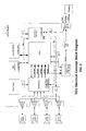
FIG. 2 is a schematic of a vehicular system in accordance with the present invention;
FIG. 3 is a schematic of a vehicular multi-view camera system of the present invention;
FIG. 4 is a schematic of a vehicular multi-view camera system and easy park system in accordance with the present invention;
FIGS. 5 and 6 are schematics of a vehicular scalable control system in accordance with the present invention;
FIG. 7 is a perspective view and schematic of a vehicle incorporating an integrated vehicle control system of the present invention;
FIGS. 8 and 9 are schematics of a system architecture for a vehicle control system of the present invention;
FIGS. 10-14 are schematics of examples of the control functions of the vehicle control system of the present invention;
FIG. 15 is a schematic of various accessories and systems that may be incorporated into an integrated vehicle control system of the present invention;
FIG. 16 is a schematic of vehicle driving segments or hierarchy for use by the integrated vehicle control system of the present invention;
FIG. 17 is a top plan view of a vehicle and a schematic of an integrated vehicle control system of the present invention, incorporated into the vehicle;
FIG. 18 is another schematic of a vehicle control system of the present invention, showing various inputs to the control;
FIG. 19 is another schematic of a vehicle control system of the present invention suitable for use in a fully autonomous vehicle;
FIGS. 20-22 are schematics of the software architecture for the vehicle control system of the present invention; and
FIG. 23 is a block diagram of another vehicle control system of the present invention.
DESCRIPTION OF THE PREFERRED EMBODIMENTS
The present invention provides a vehicular scalable integrated control unit or module or system that is responsive to inputs from multiple accessories and/or systems or subsystems and is operable to control or adjust or activate/deactivate various accessories or vehicle controls. The vehicular scalable electronic control unit provides a single or common or central control or processor that may provide various functions depending on detected or determined driving conditions or situations and/or vehicle conditions and/or weather conditions and/or geographical location of the vehicle and/or the like. The vehicular scalable electronic control unit provides dynamic situational processing and provides control functions accordingly, thereby providing appropriate controls for particular situations while limiting or reducing processing of other inputs or parameters that are not as relevant to the detected or determined vehicle/driving situation. The scalable integrated electronic control unit is configurable for different applications and may selectively include different software and/or applications and may be selectively connected to different accessories or inputs, in order to provide the desired or appropriate functions for the vehicle equipped with the system. The scalable integrated electronic control unit or system of the present invention thus provides a flexible (may be configured for various applications and operating systems and the like) and scalable (may have a few functions or lots of functions available and/or running at any time) system that reduces the need for multiple isolated processors and control units of the vehicle and thus provides a lower cost control system with enhanced functional capabilities, as discussed below.
Referring now to the drawings and the illustrative embodiments depicted therein, a 360 degree view system on a vehicle may provide the driver with a view encompassing the area around the entire vehicle (FIG. 1). This type of automotive driving aid provides visual information to the driver about the vehicle surroundings and aids in the maneuvering of the vehicle. Such a system may utilize aspects of the alert systems described in PCT Application No. PCT/US2010/025545, filed Feb. 26, 2010; and/or U.S. provisional applications, Ser. No. 61/180,257, filed May 21, 2009; Ser. No. 61/156,184, filed Feb. 27, 2009; and Ser. No. 61/174,596, filed May 1, 2009, which are all hereby incorporated herein by reference in their entireties.
The system level architecture of such systems encompasses an electronic control unit (ECU) to receive live video input from a plurality of vehicular cameras, such as, for example, four separate NTSC CMOS video cameras mounted at the front, sides and rear of the vehicle (and with fields of view external of the vehicle). The vehicular scalable electronic control unit processes the individual received video feeds (or compressed data therefrom) from the individual video sources, and may perform machine vision image processing to determine objects of interest/hazard, may add indicia or icons or visual alerts or graphic overlays, may merge separate captured images into the likes of a surround-view presentation, may combine/co-process the received video images with other received data, such as from the likes of ultrasonic or radar or IR sensors or from other vehicle equipment/accessories/sensors, and may present/feed (such via a vehicular network or via a direct wired connection) that information to a video display viewable by the driver (such as a console-mounted video screen or a video mirror) and/or may generate vehicle equipment control signals/outputs that control the likes of braking or speed or hazard alerts or the like. The presentation of this video information on a video screen viewable by the driver while driving preferably has driver-selectable viewing configurations including: a 360 degree view with a perspective reference above the vehicle (birds-eye view) for the purpose of identifying obstacles about the vehicle, and the system provided selection of any single camera in full screen mode to provide more information about the region of interest, and a rearward looking view of the vehicle to aid in maneuvering the vehicle while moving in reverse. FIG. 2 shows the system level block diagram of the 360 degree view system.
Such a system can have an architecture such as shown in FIG. 2. FIG. 2 illustrates the inclusion of the NTSC Decoder, video processor, and NTSC encoder. In addition, a stand alone microcontroller may support MSCAN communication, power supply management, system state control, system configuration, and act as a co-processor for generating algorithm dependent overlays.
FIG. 3 shows a block diagram of a vehicular scalable electronic control unit or module or system in accordance with the present invention. The advantages of the system shown in FIG. 3 include, for example, that the scalable integrated electronic control unit can be used for other functions when the 360 view camera system is not needed/used; the scalable integrated electronic control unit has the capability to run other functions in addition to the 360 view system; and the system has the ability to use cameras for other applications when not used by the 360 view application. The control system of the present invention thus provides a flexible, scalable, adaptable system that can be configured to receive inputs from multiple cameras and/or other sensors (such as ultrasonic or radar sensors such as shown in FIG. 4) and to provide a desirable or appropriate output or display responsive to the cameras and to a detected or selected driving condition or situation, and to provide other control functions for other accessories or systems in response to a detected or selected driving condition or situation, as discussed below.
The present invention provides a vehicle control system or driver assistance system (DAS) that is responsive to inputs from multiple sensors or accessories and operable to control various accessories, such as a video display or information display or other control systems or subsystems of the vehicle. The vehicular scalable electronic control unit or module or system thus may provide a single control unit or module that may provide multiple functions, and may automatically provide appropriate functions or processing responsive to a driving condition of the vehicle.
For example, when the system detects that the vehicle is in a reverse gear or making a reversing maneuver, the system may automatically provide a video display of the images captured by a rearward facing camera of the vehicle, and may stop or inhibit or limit processing of images captured by other cameras or sensors, such as forward facing cameras and/or the like of the vehicle. Thus, the control system provides enhanced features and functions and avoids the need for multiple isolated processors since the system manager of the control unit of the present invention dynamically, and in accordance with a particular driving, vehicle, driver, geographic, weather, traffic, and/or road condition, selectively provides a desired or appropriate degree of processing for the appropriate inputs depending on the particular driving condition or situation of the vehicle. The sensors need not include their own processors and the like, and may be readily linked to or “plugged into” the control unit or system, whereby the control unit may receive and process signals from the sensors accordingly, and depending on the particular driving condition or situation of the vehicle.
With reference to FIGS. 5-7, the vehicular scalable electronic control unit of the present invention is a scalable and integrated vehicle control unit that has the ability to host multiple core functions cost-effectively and has the ability to fuse these functions together to offer unique features that are not easily created with independent control modules. The control unit is scalable in that a common hardware architecture can be used to control multiple complex or simple functions. Customization may be provided for incorporation of functions from each system, but the common architecture will apply to each product in the control unit family. The scalable integrated electronic control unit is flexible in that functions from various vehicle subsystems can be hosted by control module, and the architecture may support any OEM and vehicle model. Also, the scalable integrated electronic control unit is flexible in that different levels/powers/types of processors may be integrated in or added to or associated with the vehicular scalable electronic control unit of the present invention, all under common system management. The scalable integrated electronic control unit is stable in that it is capable of running safety-critical functions, and its parallel processing capabilities enables redundancy for critical functions. Also, the scalable integrated electronic control unit of the present invention provides a low cost control system as compared to a vehicle equipped with equivalent functioned multiple independent processors and/or ECUs or controller (such as a Body ECU or controller, a Chassis ECU or controller, an Infotainment ECU or controller, a Head Unit ECU or controller and/or the like).
The vehicular scalable integrated control unit or module or system of the present invention thus provides a scalable generic vehicle control unit platform that supports consolidation of DAS, infotainment and chassis/body worlds/systems and that is open to host applications of different suppliers. The scalable integrated electronic control unit provides a single hardware and software architecture with plug-in capability for different software applications (such as, for example, easy adaptation of different navigation software packages), and may be operable to run safety critical vehicle functions. The scalable integrated electronic control unit or system thus allows for fewer ECUs in a vehicle equipped with the scalable integrated electronic control unit or system of the present invention, and thus provides an enhanced function to cost ratio. Because the system is a modular design, there is reduced development time and cost and a reduced piece price (because the system has the same basic components for all product lines). The openness of the platform supports integration of applications from different suppliers, and new or different applications and/or functions may be added without additional costs, based on the consolidation of DAS, infotainment, and chassis/body functions.
The scalable integrated electronic control unit or system of the present invention thus provides an operating system and software for determining which applications or programs or systems are to be controlled or processed, such as depending on a detected driving condition of the vehicle or the like. For example, the system may function to run only a few functions or may run many functions, depending on the particular driving condition or the like. The system may manage itself and continue running as the conditions change. The scalable integrated electronic control unit or system of the present invention thus provides a system with fewer ECUs (and thus reduced weight, reduced packaging concerns, fewer cables, and reduced costs to the vehicle), a reduced integration effort (and thus reduced development time, quicker product launch, enhanced stability and reduced integration risk), enhanced function to cost ratio (only one control unit or module versus multiple independent processors or control modules or units), and enhanced new features and applications (such as new features based on combined functions, enhanced aftermarket features or capabilities, a single integrated diagnosis unit and/or the like).
With reference to FIGS. 8 and 9, the control system includes a system manager, such as a Tetrahedron Control Element Topology (TCET) expander (“TeX”), that provides system management and acts as a switch board for directing signals to the appropriate component and/or subsystem and/or control. Examples of such TCET expanders and/or protocol and/or architecture are described in U.S. Pat. Nos. 6,292,718; 6,654,910; 6,628,441; 7,140,026; 5,752,065; 6,952,782; 6,571,136; 7,349,844; and/or 6,950,312, and/or U.S. Pat. Publication No. US2008/115013, published May 15, 2008, and/or European Pat. Nos. EP 1 579 279 and EP 2 954 034; and/or PCT Publication No. WO 02/095581, published Nov. 28, 2002, which are all hereby incorporated herein by reference in their entireties. The system manager or TCET system architecture facilitates enhanced system scalability and variability to allow for component reduction or minimization.
The system manager allows for scalability of the system. The system includes a Communication Access Point (CAP) that is the communication gateway for all system components including physical Firewalls and integration of external communications into a single component (such as, for example, CAN Class B/C, Most, LIN, UART, SID, LVDS, Camera Link, HMI Output—“TCET eXpander”). The CAP provides a true car gateway function using the bundled inputs and outputs. The system also includes a logical and physical separation of realtime (ComPro) and non-realtime (CoreCPU) processing. The hardware scales independent of clustered functionality using hardware/software abstraction layers, where the system may have scale in the number of processors, scale in the processor type and variety (such as logical/physical CPU, ATOM, SH4, and/or the like) and/or scale in computing power (such as changes in processing speed and/or memory of the processors). The implementation of an independent system monitor (SysMon) allows the system to monitor the complete system functionality via a TCET interlink, and allows the system to control the load balance of the associated CPUs, and allows the system to swap the functionality between logical/physical CPUs for high system availability. The interlinking of all of the relevant system components thus provides enhanced processing and control with a single control module.
For example, and with reference to FIG. 9, for a vehicle with basic functions, such as radio, keyless entry and climate control, the system may include a single low processor (such as a TI MSP430 with a SysMon and CAP on the processor) and may route the interfaces through the system manager or TCET expander to the SysMon and CAP. If additional functions are added to the vehicle or system, such as, for example, a low end navigation function or system, a multimedia function or system, an automatic headlamp control function or system and/or a lane departure warning function or system, then the system may include a single high end processor (such as an Intel ATOM 1.6 GHz processor with a CorePU, a CAP and a SysMon on the processor and with a ComPro/CorePU logical partition), and the system may route the interfaces to the core CPU through the system manager or TCET expander. If further additional functions are added to the vehicle or system, such as, for example, a mid-end navigation function or system, a traffic sign recognition function or system, a forward collision warning function or system, an adaptive cruise control function or system, a body side detection function or system, a speech recognition function or system, and/or the like, the ComPro may comprise an upgraded ComPro (such as an SH7785 600 MHz ComPro) and the CorePU may comprise an upgraded or separate CorePU (such as an Intel ATOM 1.3 GHz CorePU) to provide the enhanced processing capabilities. Optionally, if further additional functions are added to the vehicle or system, such as, for example, a 3D navigation system, a natural speech recognition function or system, a heads up display, a Stop&Go function or system, and/or the like, the ComPro may comprise an upgraded ComPro (such as an Intel ATOM 1.3 GHz ComPro) and the CorePU may comprise an upgraded or separate CorePU (such as an Intel ATOM 1.6 GHz CorePU), and the processor may include CorePU and ComPro physical partitions, with the system providing dynamic routing of interfaces to the CorePU and ComPro through the system manager or TCET expander to provide the enhanced processing capabilities and dynamic processor utilization (and the system may have multiple operating system capabilities).
The scalable integrated electronic control unit or module or system thus allows for the vehicle manufacturer or an aftermarket supplier to provide different applications for performing different functions, without requiring a new or additional processor. For example, a desired application or applications may be downloaded (such as from the INTERNET by a consumer or by a technician at a car dealership/car service center or via a telematics system of the vehicle by the driver/car owner himself or herself) to the scalable integrated electronic control unit or module or system as desired. Optionally, and such as via a telematics system of the vehicle, and when selected by a driver of the vehicle while driving or when automatically triggered such as for a particular driving situation and/or geographical location of the vehicle (that automatically is determined by a GPS system of the equipped vehicle), the scalable integrated electronic control unit may operate to access or run the downloaded application or applications at an appropriate time or in response to a detected driving condition or the like. The system thus may have programs from different sources, and the programs may be fed to the TCET expander, whereby information that is important for the selected or appropriate processing may be extracted from the programs and routed to the appropriate processor or accessory or the like. As shown in FIGS. 10-21, various systems and/or subsystems and/or accessories may be integrated into the control system of the present invention, with the scalable integrated electronic control unit providing an integrated control unit or vehicle control unit or module.
For example, the vehicular scalable electronic control unit or system or situational awareness unit or module or system can be particularly used in an overall driver assistance and safety system as illustrated in FIGS. 17 and 18. As further applications and systems and subsystems are developed and integrated into the vehicular scalable electronic control unit, it is envisioned that the vehicular scalable integrated control unit of the present invention may be suitable for controlling functions of an autonomous vehicle, such as illustrated in FIG. 19. Various software and software architecture may be implemented in or associated with the vehicular scalable integrated control unit, such as illustrated in FIGS. 20-22.
Optionally, for example, the control system may include an automatic headlamp control function, a traffic sign recognition function, a back up assist function and/or the like, responsive to various image sensors (such as a forward facing sensor and rearward facing sensor) and non-imaging sensors or the like. The system may analyze various inputs or vehicle status conditions to determine the type of driving that the vehicle is undergoing, and may adjust the processing in response to such a determination. For example, if the system determines that the vehicle is undergoing a reversing maneuver, the system may limit or inhibit processing of the captured images from the forward facing camera, since they are not as relevant for a reversing maneuver. Likewise, if the system determines via inputs from sensors/equipment in the vehicle that the vehicle is traveling in a forward direction, the system recognizes that there is no need to have the processor process images from the rearward facing camera and that there is no need to even have the rearward facing camera operating to be available for processing when the vehicle is in a forward gear. Thus, the system may detect the vehicle driving situation (such as driving forward, driving in reverse, driving up a hill or mountain, driving down a hill or mountain, driving around a curve in the road, daytime driving, nighttime driving, driving at a particular geographical location, and/or the like), and may adjust its processing accordingly. Thus, a single scalable integrated electronic control unit or module may function to provide a plurality of independent functions without requiring costly high end or high powered processing capabilities and the like.
Optionally, for example, a navigation application may be downloaded (such as via a telematics system of the vehicle when selected by a driver of the vehicle, such as for a particular driving situation and/or geographical location of the vehicle) for a particular region or locale that the vehicle is to be traveling in or through. Then, when a GPS system of the vehicle detects that the vehicle is at a particular geographical location, the scalable integrated electronic control unit may download the appropriate maps or information associated with that location, or may provide (such as via an audible system or video display or the like) information to the driver of the vehicle about the geographical location at which the vehicle is located.
For example, and with reference to FIG. 23, a vehicular scalable integrated control system for a vehicle may include a plurality of cameras having respective fields of view exterior of the vehicle (such as a forward facing camera, a rearward facing camera and one or more sideward and/or rearward facing cameras), and a vehicular scalable integrated control unit. The vehicular scalable integrated control unit includes an image processor, and visual image data captured by the cameras is processed by the image processor of the vehicular scalable integrated control unit to detect objects in the fields of view of the cameras. A display screen for displaying video information to a driver of the vehicle is operable to display information responsive to the vehicular scalable integrated control unit. The vehicular scalable integrated control unit is responsive to a global positioning system of the vehicle to determine a current geographical location of the vehicle. The vehicular scalable integrated control unit accommodates downloading of applications, which may include a tour guide application (for example, if a driver is planning to visit a tourist attraction area, such as, for example, Washington, D.C., the driver may download a Washington, D.C. tour guide application to provide him or her with maps and points of interest at the tour area). The tour guide application provides information associated with various geographical locations of a selected tour area. The vehicular scalable integrated control unit, responsive to a determination by a GPS system of the equipped vehicle that the current geographical location of the vehicle is at a location identified in the tour guide application for the selected tour area, controls the display screen to display information associated with the identified location of the tour guide application and the current geographical location of the vehicle and/or audibly narrates points of historical, entertainment or commercial interest associated with the building or site or landmark or the like being approached/passed. A video image of a historical building being capture by a forward facing camera can be highlighted/annotated to draw the driver's/occupant's attention to what is being approached/passed. Optionally, the vehicular scalable integrated control unit may be operable to access and/or process the tour guide application responsive to a determination that the current geographical location of the vehicle is approaching the selected tour area.
Thus, when the vehicle is driven at or through the tour area associated with the downloaded tour guide application, the display screen displays information responsive to the vehicular scalable integrated control unit and the GPS, with the displayed information being associated with the selected tour location of the tour guide application and the current geographical location of the vehicle. For example, as the vehicle approaches or is at the tour area (such as Washington, D.C.), the control unit may automatically access and process or run the tour guide application for that area and may display pertinent information on the display screen as the vehicle is driven through the tour area. For example, as the vehicle is driven past the White House, the control unit may (responsive to a detection of that current geographical location of the vehicle) automatically display information about the White House such as a video of the White House being captured by a forward-facing camera of the equipped vehicle (along with audible information as well) so the driver and occupants of the vehicle can readily identify the White House and see or hear additional information about the White House as the vehicle approaches or is driven past the White House, or a video downloaded from the INTERNET from the likes of Google Street View (http://maps.google.com/help/maps/streetview/) can be displayed as the equipped vehicle approaches the actual building/site, with the display of the video synchronized to the actual geographic position and approach of the equipped vehicle.
The vehicular scalable integrated control unit thus provides flexible customization of the control unit to provide a consumer-attractive tour guide feature or function, whereby the driver may purchase and download the desired tour guide application (including maps and information) such as from the INTERNET using his/her PDA or cell phone or the like or via a vehicular telematics system such as SYNC™ or ONSTAR®, and may select (and authorize/pay for) the type of information or type of tour (e.g., a points of interest type of tour or a historical information type of tour or a scenic type of tour or the like), and the control unit or system automatically accesses and runs the application when it is determined that the vehicle is at or approaching the selected tour guide area (or in response to a user input or the like). The driver and occupants of the vehicle can then take a self driven tour of the selected tour area while automatically receiving information on the various points of interest that they pass during the tour and receiving such information at the time that the vehicle is actually present at or approaching or driving past that particular point of interest.
The vehicular scalable integrated control unit thus performs situational processing to determine the driving conditions (such as forward/reverse/uphill/downhill and/or weather conditions and/or fuel capacity or driving range or the like) and/or the current geographical location of the vehicle and/or the like, and may access and run or control the appropriate application and/or accessory responsive to such a determination. Optionally, for example, a fuel conserving program or application may be downloaded to the processor or system, whereby when the system detects that the vehicle is low on fuel (such as low on gasoline or low on battery power for an electric vehicle), the system may provide hierarchical situational analysis and decision making to provide enhanced fuel economy while the fuel or energy level is low. For example, the system may, in response to a low fuel/energy/power detection, function to control the HVAC system of the vehicle, such as to shut down the air conditioning to conserve energy. Optionally, for example, the system may inhibit or limit such controlling or shutting down of the HVAC system if the system also determines that there is fog on the interior surface of the windshield (such as responsive to a rain sensor or imaging sensor or the like at or near the windshield of the vehicle). The system dynamically analyzes the inputs and conditions and makes the decision based on the hierarchical analysis. For example, at first, the importance is on getting to a gas station or charging station or the like without running out of fuel, so the system may shut down any accessory or system that may be a drain on the vehicle power, but if that accessory is at that time needed (such as an AC function to defog the windshield for safer driving), then the system may limit or inhibit shutting down that system and may look to shutting down other accessories or systems or controlling the engine performance or the like to enhance the fuel economy of the vehicle until it is refueled or recharged.
The vehicular scalable integrated control unit may allow an automaker to flexibly and freely centralize the computer/algorithmic processing of features and applications that conventionally are processed in isolation, and further allows and enables selection by the automaker of a preferred or specialized or more affordable software supplier that may be independent of the supplier of the vehicular scalable integrated control unit and/or the various sensors/controls/subsystems/systems/accessories that provide and/or receive data or I/O control thereto or therefrom. Optionally, the vehicular scalable integrated control unit comprises a scalable DAS situational analysis vehicle integrated control unit that also provides control of functions or systems or accessories of the vehicle, and that can accommodate and run consumer-attractive applications. Such applications may be customized for or be appropriate for a particular type or brand or level of vehicle, or a particular type or level of driver and/or profile identity of the driver and/or occupants of the vehicle, or a particular driving situation and/or geographic location and/or traffic condition. For example, the vehicular scalable integrated control unit may run or accommodate such applications and may be responsive to the geographic location of the vehicle or a detected identity of the driver or occupants of the vehicle, such as by utilizing aspects of the systems described in U.S. Pat. Nos. 7,412,328 and/or 7,474,963, which are hereby incorporated herein by reference in their entireties.
The system thus provides dynamic situational processing to provide the appropriate function depending on one or more conditions of the vehicle and/or driver and/or vehicle location and/or weather conditions and/or the like. Optionally, the system may also function to mitigate problems that may arise in case of a malfunction of one or more accessories or subsystems. For example, if the system detects a problem or malfunction or error in a software application or hardware component, the system may dynamically shut down the malfunctioning application or component (such as a processor) and may use another application or component (such as another processor) to perform the desired or appropriate task or may share circuitry and/or components with other systems or subsystems or software to perform the desired or appropriate task.
Optionally, the vehicular scalable integrated control unit or module may be located in variety of locations at or in the vehicle. For example, the scalable integrated electronic control unit may be located at or incorporated in or associated with an infotainment element or system (such as part of a radio or navigation screen or a video display module or part of a video mirror assembly or the like). Optionally, the scalable integrated electronic control unit may be incorporated in or may be part of a windshield electronics module and/or an accessory module located at or near the interior rearview mirror assembly of the vehicle, or may be located at or in the interior rearview mirror assembly of the vehicle, while remaining within the spirit and scope of the present invention.
As discussed above, the vehicular scalable integrated control unit receives inputs from various exterior cameras and/or sensors, and outputs from the scalable integrated electronic control unit may be used for displaying captured video information on a video display screen. Thus, the scalable integrated electronic control unit may be associated with or may cohabitate with other units or systems or accessories associated with a video screen or imaging system of the vehicle. Because many other items or accessories or systems may generate information or outputs that appear on such a video screen, it is ripe to cohabitate or coassociate the vehicular scalable electronic control unit with such other accessories or system or component items that currently are associated with or use video screens of a vehicle (like navigation systems and the like). Thus, it is envisioned that the vehicular scalable electronic control unit of the present invention and these other systems or subsystems or accessories (such as an image processor, such as an EyeQ™ image processor or the like) may be brought into or associated with or located at the “Head Unit” of the vehicle using scalable integrated electronic control unit (or optionally elsewhere at or in the vehicle).
The cameras may communicate the captured image data to the scalable integrated electronic control unit via any suitable means. For example, the cameras may wirelessly communicate the captured image data to the image processor or may communicate via a wired connection or communication link or Ethernet cable or link. For economy, video image transmission via an Ethernet cable can be desirable, particularly when the individual video feeds from multiple video cameras disposed around the vehicle are being fed to a common image processor and/or electronic control unit and/or video display module or system. Optionally, for example, the connection or link between the image processor and the camera or cameras may be provided via vehicle electronic or communication systems and the like, and may be connected via various protocols or nodes, such as BLUETOOTH®, SCP, UBP, J1850, CAN J2284, Fire Wire 1394, MOST, LIN, FLEXRAY®, Byte Flight, LVDS and/or the like, or other vehicle-based or in-vehicle communication links or systems (such as WIFI and/or IRDA) and/or the like, depending on the particular application of the mirror/accessory system and the vehicle, and may be compatible with standard vehicle protocols/conventions such as are provided by the likes of AUTOSAR. Optionally, the connections or links may be provided via wireless connectivity or links, such as via a wireless communication network or system, such as described in U.S. Pat. No. 7,004,593, which is hereby incorporated herein by reference in its entirety, without affecting the scope of the present invention. Data processing is flexible to be compatible with various real-time operating systems such as QNX or Linux or Microsoft CE or Microsoft Auto® or the like. Abstraction action of particular hardware and/or running of particular software is managed via a respective hardware abstraction layer and a software abstraction layer of the scalable integrated electronic control unit or module or system. The system manager scalable integrated electronic control unit or module or system (preferably comprising a TCET expander) functions as an overall system sentinel that manages the firewalls provided for data/processing and of I/O, that manages the flexibility and scalability of I/O, of multiple data-processors used, of memory and other data storage resources, of sub-system redundancy/fault recovery, of communications and of dynamic, and of situational awareness and/or the like.
Optionally, for example, if the vehicle is being driven in a forward direction, the forward facing camera may be operating to capture images for a lane departure warning system (LDW) or the like, with the captured image data being processed accordingly (such as by utilizing aspects of the systems described in U.S. Pat. Nos. 7,355,524; 7,205,904; 7,038,577; 5,929,786 and/or 5,786,772, and/or U.S. patent applications, Ser. No. 11/239,980, filed Sep. 30, 2005; and/or Ser. No. 11/315,675, filed Dec. 22, 2005, now U.S. Pat. No. 7,720,580, which are hereby incorporated herein by reference in their entireties). If the vehicle is then stopped, the system, responsive to the changed driving condition, may determine that the vehicle is stopped at a cross-traffic situation, such as via image processing to detect a stop sign or the like (such as by utilizing aspects of the systems described in U.S. Pat. Nos. 5,550,677; 5,670,935; 5,796,094; 5,877,897; 6,313,454; 6,353,392 6,396,397; 6,498,620; 7,004,606; 7,038,577; and/or 7,526,103, which are hereby incorporated herein by reference in their entireties) or by determining that the vehicle had been driving in a forward direction and then stopped moving. In response to such a determination that the vehicle is stopped at a cross-traffic situation, the video display, responsive to the image processor, may display the sideward directed views to assist the driver in driving forward into the intersection or out of a parking space in a parking lot or the like, such as described in PCT Application No. PCT/US2010/025545, filed Feb. 26, 2010; and/or U.S. provisional applications, Ser. No. 61/180,257, filed May 21, 2009; Ser. No. 61/156,184, filed Feb. 27, 2009; and Ser. No. 61/174,596, filed May 1, 2009, which are all hereby incorporated herein by reference in their entireties.
Optionally, the vision system may process the captured image data and/or may be associated with a navigation system to determine the location of the vehicle, such as to determine if the vehicle is in an urban environment or rural environment or the like. The navigation system may comprise any type of navigation system, and may utilize aspects of the systems described in U.S. Pat. Nos. 6,477,464; 5,924,212; 4,862,594; 4,937,945; 5,131,154; 5,255,442; 5,632,092; 7,004,593; 6,678,614; 7,167,796; and/or 6,946,978, which are all hereby incorporated herein by reference in their entireties. Optionally, the vehicle speed may be determined via processing of the images captured by the imaging sensors or cameras, such as by utilizing aspects of the systems described in U.S. Pat. No. 7,038,577, which is hereby incorporated herein by reference in its entirety. The system thus may take into account the driving conditions or geographic location of the vehicle in making the decision of whether or not to display the sideward views when it is determined that the vehicle has stopped at a potential cross-traffic driving situation.
Optionally, the system may determine that the vehicle is in or at another driving condition, such as, for example, a parallel parking situation. Such a condition may be determined by processing the captured image data and detecting the equipped vehicle being driven alongside a vacant parking space and being shifted into reverse to back into the vacant parking space. In such a situation, the video display may provide an overview of the vehicle (such as an iconistic representation of the vehicle showing the distances to vehicles or objects forward and rearward of the equipped vehicle, such as in a known manner).
The system of the present invention may be part of an overall active safety and sensing system, which may comprise the combination of machine vision activity or monitoring (such as for a lane departure warning system and/or the like) and vehicle control (such as via body/chassis sensors and sensing). The active safety and sensing system may include fusion/combination of outputs from various sensing devices to provide environmental awareness at and surrounding the vehicle and may provide partial or complete control of the vehicle as it is driven along a road and/or may provide alert warnings to the driver of the vehicle of what may be present environmentally exterior of the vehicle and/or what may be hazardous thereat. Machine vision forward facing cameras may be used to provide lane departure warning (LDW), traffic sign recognition (TSR), forward collision warning (FCW), pedestrian detection, vehicle detection, hazard detection and/or the like, and these systems may communicate with or cooperate with other systems, such as intelligent headlamp control or automatic headlamp control (AHC), intelligent light ranging (ILR) (a combination of AHC and ILR may be used for a glide path automatic headlamp control, for example, where the headlamps are actively or dynamically adjusted so that the beam pattern forward of the equipped vehicle can be configured to illuminate the road just ahead of an approaching vehicle), lane keep assist (LKA) (where the steering wheel may variably provide resistance to turning to further alert the driver of a detected potentially hazardous condition and/or may actively turn or control the steering system of the vehicle so as to mitigate or avoid an imminent potential collision) and/or the like.
Optionally, an LDW system or function may be extended to an LKA system or function by tracking the lane along which the vehicle is driven and controlling the steering torque to aid the driver in maintaining the vehicle in the lane. Optionally, the system may include a map input or geographical location input (such as from an onboard or an, external GPS-based navigational system), whereby the vehicle safety system may be geographically/locally customized to operate differently or may process the image data differently or the like, in response to the map input or geographical location input indicative of the particular geographical location of the equipped vehicle at that moment in time. Optionally, and preferably, the map data/GPS derived information relating to, for example, the curvature and/or bank angle of a highway exit or entrance ramp may tie into the automatic headlamp control and/or the direction control of the headlamp beam. Optionally, for example, map data (such as longitude/latitude/altitude coordinates) may be provided in connection with or fused with a TSR system and/or an AHC/ILR system and/or an automatic cruise control (ACC) system to enhance performance of the TSR system and/or the AHC/ILR system and/or the ACC system. Optionally, the system may receive inputs from a Car2Car telematics communication system or a Car2X telematics communication system or the like.
Optionally, camera data or information may be fused with radar data or information (or with other non-vision based data, such as from ultrasonic sensors or infrared sensors or the like) to derive object information and emergency braking may be initiated in response to such object detection. Optionally, an LKA system and emergency braking system may cooperate to provide semi-autonomous driving. The system may utilize aspects of the systems described in U.S. Pat. No. 7,697,027, which is hereby incorporated herein by reference in its entirety.
Optionally, the image processor of the system may comprise an advanced image processing platform, such as, for example, an EyeQX image processing chip, such as an EyeQ2 or an EyeQ1 image processing chip available from Mobileye Vision Technologies Ltd. of Jerusalem, Israel, such as described in PCT Application No. PCT/US2010/025545, filed Feb. 26, 2010, which published on Sep. 2, 2010 as International Publication No. WO2010099416; and/or U.S. provisional applications, Ser. No. 61/180,257, filed May 21, 2009; Ser. No. 61/156,184, filed Feb. 27, 2009; and Ser. No. 61/174,596, filed May 1, 2009, which are all hereby incorporated herein by reference in their entireties.
The video display screen device or module may comprise any suitable type of video screen and is operable to display images in response to an input or signal from a control or imaging system. For example, the video display screen may comprise a multi-pixel liquid crystal module (LCM) or liquid crystal display (LCD), preferably a thin film transistor (TFT) multi-pixel liquid crystal display (such as discussed below), or the screen may comprise a multi-pixel organic electroluminescent display or a multi-pixel light emitting diode (LED), such as an organic light emitting diode (OLED) or inorganic light emitting diode display or the like, or a passive reflective and/or backlit pixelated display, or an electroluminescent (EL) display, or a vacuum fluorescent (VF) display or the like. For example, the video display screen may comprise a video screen of the types disclosed in U.S. Pat. Nos. 7,446,650; 7,370,983; 7,338,177; 7,274,501; 7,255,451; 7,195,381; 7,184,190; 6,902,284; 6,690,268; 6,428,172; 6,420,975; 5,668,663; 5,724,187, and/or U.S. patent applications, Ser. No. 12/414,190, filed Mar. 30, 2009, now U.S. Pat. No. 8,154,418; Ser. No. 10/538,724, filed Jun. 13, 2005, which published on Mar. 9, 2006 as U.S. Patent Publication No. 2006/0050018; Ser. No. 11/226,628, filed Sep. 14, 2005, which published on Mar. 23, 2006 as U.S. Patent Publication No. 2006/0061008; Ser. No. 12/091,525, filed Apr. 25, 2008, now U.S. Pat. No. 7,855,755; Ser. No. 09/585,379, filed Jun. 1, 2000, now abandoned; Ser. No. 10/207,291, filed Jul. 29, 2002, which published on Jan. 9, 2003 as U.S. Patent Publication No. US 2003/0007261; and/or Ser. No. 12/578,732, filed Oct. 14, 2009, which published on Apr. 22, 2010 as U.S. Patent Publication No. 2010/0097469, which are hereby incorporated herein by reference in their entireties. Optionally, video displays may be disposed at the rearview mirror assemblies and may be operable to display video images of the rearward scene, such as by utilizing aspects of the displays described in U.S. patent application Ser. No. 11/933,697, filed Nov. 1, 2007, now U.S. Pat. No. 7,777,611, which is hereby incorporated herein by reference in its entirety. Each mirror thus may provide a video display (such as including a video display screen disposed behind and viewable through a transflector or transflective mirror reflector of a reflective element) and the display may be larger if provided as a display-on-demand type of display behind a transflective mirror reflector of the reflective element and viewable through the transflective mirror reflector of the reflective element.
Optionally, the video display module may provide a graphic overlay to enhance the driver's cognitive awareness of the distances to objects to the rear of the vehicle (such as by utilizing aspects of, he systems described in U.S. Pat. Nos. 5,670,935; 5,949,331; 6,222,447; and 6,611,202; and/or PCT Application No, PCT/US08/76022, filed Sep. 11, 2008, which published on Mar. 19, 2009 as International Publication No. WO 2009/036176, which are hereby incorporated herein by reference in their entireties. Such graphic overlays may be generated at or by the camera circuitry or the mirror or display circuitry. Optionally, the display module may comprise a high luminance 3.5 inch video display or a 4.3 inch video display, preferably having a display intensity of at least about 400 candelas per square meter (cd/m2) as viewed through the reflective element (preferably as viewed through a transflective mirror reflector of the transflective reflective element) by a person viewing the mirror reflective element, more preferably at least about 1000 cd/m2 as viewed through the reflective element (preferably as viewed through a transflective mirror reflector of the transflective reflective element) by a person viewing the mirror reflective element, and more preferably at least about 1500 cd/m2 as viewed through the reflective element (preferably as viewed through a transflective mirror reflector of the transflective reflective element) by a person viewing the mirror reflective element.
The imaging device and control and image processor may comprise any suitable components, and may utilize aspects of the cameras and vision systems described in U.S. Pat. Nos. 5,550,677; 5,877,897; 6,498,620; 5,670,935; 5,796,094; 6,396,397; 6,806,452; 6,690,268; 7,005,974; 7,123,168; 7,004,606; 6,946,978; 7,038,577; 6,353,392; 6,320,176; 6,313,454; and 6,824,281, which are all hereby incorporated herein by reference in their entireties. Optionally, the circuit board or chip may include circuitry for the imaging array sensor and or other electronic accessories or features, such as by utilizing compass-on-a-chip or EC driver-on-a-chip technology and aspects such as described in U.S. Pat. Nos. 7,255,451 and/or 7,480,149, and/or U.S. patent application Ser. No. 11/226,628, filed Sep. 14, 2005, which published on Mar. 23, 2006 as U.S. Patent Publication No. US 2006/0061008, which are hereby incorporated herein by reference in their entireties. The camera or camera module may comprise any suitable camera or imaging sensor, and may utilize aspects of the cameras or sensors described in U.S. Pat. No. 7,480,149 and/or U.S. patent applications, Ser. No. 12/091,359, filed Apr. 24, 2008, which published on Oct. 1, 2009 as U.S. Patent Publication. No. US 2009/02443361; and/or Ser. No. 10/534,632, filed. May 11, 2005, now U.S. Pat. No. 7,965,336; and/or U.S. provisional application Ser. No. 61/303,054, filed Feb, 10, 2010, which are all hereby incorporated herein by reference in their entireties. The imaging array sensor may comprise any suitable sensor, and may utilize various imaging sensors or imaging array sensors or cameras or the like, such as a CMOS imaging array sensor, a CCD sensor or other sensors or the like, such as the types described in U.S. Pat. Nos. 5,550,677; 5,670,935; 5,760,962; 5,715,093; 5,877,897; 6,922,292; 6,757,109; 6,717,610; 6,590,719; 6,201,642; 6,498,620; 5,796,094; 6,097,023; 6,320,176; 6,559,435; 6,831,261; 6,806,452; 6,396,397; 6,822,563; 6,946,978; 7,339,149; 7,038,577; and 7,004,606; and/or U.S. patent applications Ser. No 11/315,675, filed Dec. 22, 2005, now U.S. Pat. No. 7,720,580; and/or PCT Application No. PCT/US2003/036177 filed Nov. 14, 2003, and published Jun. 3, 2004 as PCT Publication No. WO 2004/047421, and/or PCT Application No. PCT/US2008/076022, filed Sep. 11, 2008, and/or PCT Application No. PCT/US2008/078700, filed Oct. 3, 2008, which are all hereby incorporated herein by reference in their entireties.
The control module of the present invention may be implemented and operated in connection with various vehicular vision-based systems, and/or may be operable utilizing the principles of such other vehicular systems, such as a vehicle headlamp control system, such as the type disclosed in U.S. Pat. Nos. 5,796,094; 6,097,023; 6,320,176; 6,559,435; 6,831,261; 7,004,606; and 7,339,149, and U.S. patent application Ser. No. 11/105,757, filed Apr. 14, 2005, now U.S. Pat. No. 7,526,103, which are all hereby incorporated herein by reference in their entireties, a rain sensor, such as the types disclosed in commonly assigned U.S. Pat. Nos. 6,353,392; 6,313,454, and/or 6,320,176, and/or U.S. patent application, Ser. No. 11/201,661, filed Aug. 11, 2005, now U.S. Pat. No. 7,480,149, which are hereby incorporated herein by reference in their entireties, a vehicle vision system, such as a forwardly, sidewardly or rearwardly directed vehicle vision system utilizing principles disclosed in U.S. Pat. Nos. 5,550,677; 5,670,935; 5,760,962; 5,877,897; 5,949,331; 6,222,447; 6,302,545; 6,396,397; 6,498,620; 6,523,964; 6,611,202; 6,201,642; 6,690,268; 6,717,610; 6,757,109; 6,802,617; 6,806,452; 6,822,563; 6,891,563; 6,946,978; 7,205,904; and 7,355,524, and/or in U.S. patent application Ser. No. 10/643,602, filed Aug. 19, 2003, now U.S. Pat. No. 7,859,565, which are all hereby incorporated herein by reference in their entireties, a trailer hitching aid or tow check system, such as the type disclosed in U.S. Pat. No. 7,005,974, which is hereby incorporated herein by reference in its entirety, a reverse or sideward imaging system, such as for a lane change assistance system or lane departure warning system or for a blind spot or object detection system, such as imaging or detection systems of the types disclosed in U.S. Pat. Nos. 7,355,524; 7,205,904; 7,038,577; 5,929,786 and/or 5,786,772, and/or U.S. patent applications, Ser. No. 11/239,980, filed Sep. 30, 2005, now U.S. Pat. No. 7,881,496; and/or Ser. No. 11/315,675, filed Dec. 22, 2005, now U.S. Pat. No. 7,720,580, and/or U.S. provisional applications, Ser. No. 60/628,709, filed Nov. 17, 2004; Ser. No. 60/614,644, filed Sep. 30, 2004; Ser. No. 60/618,686, filed Oct. 14, 2004; Ser. No. 60/638,687, filed Dec. 23, 2004, which are hereby incorporated herein by reference in their entireties, a video device for internal cabin surveillance and/or video telephone function, such as disclosed in U.S. Pat. Nos. 5,760,962; 5,877,897; 6,690,268; and/or 7,370,983, and/or PCT Application No. PCT/US03/40611, filed Dec. 19, 2003 by Donnelly Corp. et al. for ACCESSORY SYSTEM FOR VEHICLE, and published Jul. 15, 2004 as PCT Publication No. WO 2004/058540, and/or U.S. patent application Ser. No. 10/538,724, filed Jun, 13, 2005 and published Mar. 9, 2006 as U.S. Publication No. US-2006-0050018-A1, and/or U.S. provisional applications, Ser. No. 60/630,061, filed Nov. 22, 2004; and Ser. No. 60/667,048, filed Mar. 31, 2005, which are hereby incorporated herein by reference in their entireties, a traffic sign recognition system, a system for determining a distance to a leading or trailing vehicle or object, such as a system utilizing the principles disclosed in U.S. Pat. Nos. 6,396,397 and/or 7,123,168, which are hereby incorporated herein by reference in their entireties, and/or the like.
Optionally, the system may selectively control or operate alert devices or indicators, such as for the exterior rearview mirror assemblies, may utilize aspects of blind spot indicators or the like, such as indicators or light modules of the types described in U.S. Pat. Nos. 7,492,281; 6,227,689; 6,582,109; 5,371,659; 5,497,306; 5,669,699; 5,823,654; 6,176,602; 6,276,821; 6,198,409; 5,929,786; and 5,786,772, and/or U.S. patent applications, Ser. No. 11/226,628, filed Sep. 14, 2005 by Kamer et al., which published on Mar. 23, 2006 as U.S. Patent Publication No. US 2006/0061008; Ser. No. 11/520,193, filed Sep. 13, 2006, now U.S. Pat. No. 7,581,859; and/or Ser. No. 11/912,576, filed Oct. 25, 2007, now U.S. Pat. No. 7,626,749, and/or PCT Application No. PCT/US2006/026148, filed Jul. 5, 2006, which published Jan. 11, 2007 as International Publication No. WO 2007/005942, and/or PCT Application No. PCT/US07/82099, filed Oct. 22, 2007, which published May 2, 2008 as International Publication No. WO 2008/051910, and/or PCT Application No. PCT/US2006/018567, filed May 16, 2006 and published Nov. 23, 2006 as International Publication No. WO 2006/124682, and/or U.S. provisional applications, Ser. No. 61/351,513, filed Jun. 4, 2010; and/or Ser. No. 61/238,862, filed Sep. 1, 2009, which are hereby incorporated herein by reference in their entireties.
Optionally, the interior and/or exterior mirror assemblies may comprise an electro-optic or electrochromic mirror assembly and may include an electro-optic or electrochromic reflective element. The electrochromic mirror element of the electrochromic mirror assembly may utilize the principles disclosed in commonly assigned U.S. Pat. Nos. 6,690,268; 5,140,455; 5,151,816; 6,178,034; 6,154,306; 6,002,544; 5,567,360; 5,525,264; 5,610,756; 5,406,414; 5,253,109; 5,076,673; 5,073,012; 5,117,346; 5,724,187; 5,668,663; 5,910,854; 5,142,407 and/or 4,712,879, which are hereby incorporated herein by reference in their entireties, and/or as disclosed in the following publications: N. R. Lynam, “Electrochromic Automotive Day/Night Minors”, SAE Technical Paper Series 870636 (1987); N. R. Lynam, “Smart Windows for Automobiles”, SAE Technical Paper Series 900419 (1990); N. R. Lynam and A. Agrawal, “Automotive Applications of Chromogenic Materials”, Large Area Chromogenics: Materials and Devices for Transmittance Control, C.M. Lampert and C.G. Granquist, EDS., Optical Engineering Press, Wash. (1990), which are hereby incorporated by reference herein in their entireties; and/or as described in U.S. Pat. No. 7,195,381, which is hereby incorporated herein by reference in its entirety. Optionally, the electrochromic circuitry and/or a glare sensor (such as a rearward facing glare sensor that receives light from rearward of the mirror assembly and vehicle through a port or opening along the casing and/or bezel portion and/or reflective element of the mirror assembly) and circuitry and/or an ambient light sensor and circuitry may be provided on one or more circuit boards of the mirror assembly. The mirror assembly may include one or more other displays, such as the types disclosed in U.S. Pat. Nos. 5,530,240 and/or 6,329,925, which are hereby incorporated herein by reference in their entireties, and/or display-on-demand transflective type displays, such as the types disclosed in U.S. Pat. Nos. 7,274,501; 7,255,451; 7,195,381; 7,184,190; 5,668,663; 5,724,187 and/or 6,690,268, and/or in U.S. patent applications, Ser. No. 11/226,628, which published on Mar. 23, 2006 as U.S. Patent Publication No. 2006/0061008, filed Sep. 14, 2005; Ser. No. 10/538,724, filed Jun. 13, 2005, which published on Mar. 9, 2006 as U.S. Patent Publication No. 2006/0050018; and/or Ser. No. 11/912,576, filed Oct. 25, 2007, now U.S. Pat. No. 7,626,749, and/or PCT Application No. PCT/US03/29776, filed Sep. 9, 2003 by Donnelly Corp. et al. for MIRROR REFLECTIVE ELEMENT ASSEMBLY, and published Apr. 1, 2004 as International Publication No. WO 2004/026633, and/or PCT Application No. PCT/US10/29173, filed Mar. 30, 2010, which published on Aug. 7, 2010 as International Publication No. WO 2010/114825, and/or PCT Application No. PCT/US10/32017, filed Apr. 22, 2010, which published on Oct. 28, 2010 as International Publication No. WO 2010/124064, which are all hereby incorporated herein by reference in their entireties. The thicknesses and materials of the coatings on the substrates, such as on the third surface of the reflective element assembly, may be selected to provide a desired color or tint to the mirror reflective element, such as a blue colored reflector, such as is known in the art and such as described in U.S. Pat. Nos. 5,910,854; 6,420,036; and/or 7,274,501, and in PCT Application No. PCT/US03/29776, filed Sep. 9, 2003 by Donnelly Corp. et al. for MIRROR REFLECTIVE ELEMENT ASSEMBLY, and published Apr. 1, 2004 as International Publication No. WO 2004/026633, which are all hereby incorporated herein by reference in their entireties.
Optionally, the interior rearview mirror assembly may comprise a prismatic mirror assembly or a non-electro-optic mirror assembly or an electro-optic or electrochroinic mirror assembly. For example, the interior rearview mirror assembly may comprise a prismatic mirror assembly, such as the types described in U.S. Pat. Nos. 7,249,860; 6,318,870; 6,598,980; 5,327,288; 4,948,242; 4,826,289; 4,436,371; and 4,435,042; and PCT Application No. PCT/US2004/015424, filed May 18, 2004 by Donnelly Corporation et al. for MIRROR ASSEMBLY FOR VEHICLE, and published on Dec. 2, 2004, as International Publication No. WO 2004/103772, which are hereby incorporated herein by reference in their entireties. Optionally, the prismatic reflective element may comprise a conventional prismatic reflective element or prism or may comprise a prismatic reflective element of the types described in U.S. Pat. Nos. 7,420,756; 7,274,501; 7,249,860; 7,338,177; and/or 7,255,451, and/or U.S. patent application Ser. No. 12/558,892, filed Sep. 14, 2009, which published Apr. 8, 2010 as U.S. Patent Publication No. 2010/0085653, and/or PCT Application No. PCT/US03/29776, filed Sep. 19, 2003 by Donnelly Corp. et al. for MIRROR REFLECTIVE ELEMENT ASSEMBLY, and published Apr. 1, 2004 as International Publication No. WO 2004/026633; and/or PCT Application No. PCT/US2004/015424, filed May 18, 2004 by Donnelly Corporation et al. for MIRROR ASSEMBLY FOR VEHICLE, and published on Dec. 2, 2004, as International Publication No. WO 2004/103772; and U.S. provisional application, Ser. No. 60/525,952, filed Nov. 26, 2003, which are all hereby incorporated herein by reference in their entireties, without affecting the scope of the present invention. Optionally, the mirror assembly and/or display may utilize aspects of the mirror assemblies described in U.S. provisional application Ser. No. 61/332,375, filed May 7, 2010, which is hereby incorporated herein by reference in its entirety. A variety of mirror accessories and constructions are known in the art, such as those disclosed in U.S. Pat. Nos. 5,555,136; 5,582,383; 5,680,263; 5,984,482; 6,227,675; 6,229,319; and 6,315,421 (the entire disclosures of which are hereby incorporated by reference herein), that can benefit from the present invention.
Optionally, the mirror assembly and/or reflective element may include one or more displays, such as for the accessories or circuitry described herein. The displays may be similar to those described above, or may be of types disclosed in U.S. Pat. Nos. 5,530,240 and/or 6,329,925, which are hereby incorporated herein by reference in their entireties, and/or may be display-on-demand or transflective type displays, such as the types disclosed in U.S. Pat. Nos. 7,195,381; 6,690,298; 5,668,663 and/or 5,724,187, and/or in U.S. patent applications, Ser. No. 11/226,628, filed Sep. 14, 2005 by Kamer et al., which published on Mar. 23, 2006 as U.S. Patent Publication No. US 2006/0061008; and/or Ser. No. 10/993,302, filed Nov. 19, 2004, now U.S. Pat. No. 7,338,177; and/or in U.S. provisional applications, Ser. No. 60/525,952, filed Nov. 26, 2003; Ser. No. 60/717,093, filed Sep. 14, 2005; and/or Ser. No. 60/732,245, filed Nov. 1, 2005, and/or in PCT Application No. PCT/US03/29776, filed Sep. 19, 2003 by Donnelly Corp. et al. for MIRROR REFLECTIVE ELEMENT ASSEMBLY, and published Apr. 1, 2004 as International Publication No. WO 2004/026633, which are all hereby incorporated herein by reference in their entireties. Optionally, a prismatic reflective element may comprise a display on demand or transflective prismatic element (such as described in PCT Application No. PCT/US03/29776, filed Sep. 19, 2003 by Donnelly Corp. et al. for MIRROR REFLECTIVE ELEMENT ASSEMBLY, and published Apr. 1, 2004 as International Publication No. WO 2004/026633; and/or U.S. patent application, Ser. No. 10/993,302, filed Nov. 19, 2004, now U.S. Pat. No. 7,338,177; and/or U.S. provisional application, Ser. No. 60/525,952, filed Nov. 26, 2003, which are all hereby incorporated herein by reference in their entireties) so that the displays are viewable through the reflective element, while the display area still functions to substantially reflect light, in order to provide a generally uniform prismatic reflective element even in the areas that have display elements positioned behind the reflective element.
Optionally, the display and any associated user inputs may be associated with various accessories or systems, such as, for example, a tire pressure monitoring system or a passenger air bag status or a garage door opening system or a telematics system or any other accessory or system of the mirror assembly or of the vehicle or of an accessory module or console of the vehicle, such as an accessory module or console of the types described in U.S. Pat. Nos. 6,877,888; 6,824,281; 6,690,268; 6,672,744; 6,386,742; and 6,124,886, and/or, and/or PCT Application No. PCT/US03/03012, filed Jan. 31, 2003 by Donnelly Corporation for VEHICLE ACCESSORY MODULE, and published Aug. 7, 2003 as International Publication No. WO 03/065084, and/or PCT Application No. PCT/US03/40611, filed Dec. 19, 2003 by Donnelly Corporation for ACCESSORY SYSTEM FOR VEHICLE, and published Jul. 15, 2004 as International Publication No, WO 2004/058540, and/or PCT Application No. PCT/US04/15424, filed May 18, 2004 by Donnelly Corporation et al. for MIRROR ASSEMBLY FOR VEHICLE, and published on Dec. 2, 2004, as International Publication No. WO 2004/103772, which are hereby incorporated herein by reference in their entireties. The user inputs may utilize aspects of the assemblies and systems described in U.S. Pat. Nos. 6,471,362; 7,360,932; 7,255,451; 7,249,860; 7,224,324; 6,001,486; 6,310,611; 6,320,282; 6,627,918; 7,446,924; 7,253,723; 6,504,531; 6,501,465; 6,492,980; 6,452,479; 6,437,258; and/or 6,369,804, and/or U.S. patent application Ser. No. 12/576,550, filed Oct. 9, 2009, which published on Apr. 15, 2010 as U.S. Patent Publication No. US 2010/0091394, and/or PCT Application No. PCT/US03/40611, filed Dec. 19, 2003 by Donnelly Corporation for ACCESSORY SYSTEM FOR VEHICLE, and published Jul. 15, 2004 as International Publication No. WO 2004/058540; which are all hereby incorporated herein by reference in their entireties.
Changes and modifications to the specifically described embodiments may be carried out without departing from the principles of the present invention, which is intended to be limited only by the scope of the appended claims as interpreted according to the principles of patent law.

Claims (26)

The invention claimed is:
1. A vehicular scalable integrated control system for a vehicle, said vehicular scalable integrated control system comprising:
a plurality of cameras having respective fields of view exterior of the vehicle;
a vehicular scalable integrated control unit, wherein said vehicular scalable integrated control unit comprises an image processor, and wherein visual image data captured by said cameras is processed by said image processor of said vehicular scalable integrated control unit to detect objects in the fields of view of said cameras;
a display screen for displaying video information to a driver of the vehicle, and wherein said display screen displays information responsive to said vehicular scalable integrated control unit;
wherein said vehicular scalable integrated control unit is responsive to a global positioning system of the vehicle to determine a current geographical location of the vehicle;
wherein said vehicular scalable integrated control unit accommodates downloading of applications and wherein said applications include a tour guide application, said tour guide application providing information associated with various geographical locations of a selected tour area;
wherein said vehicular scalable integrated control unit, responsive to a determination that the current geographical location of the vehicle is at a location identified in said tour guide application for the selected tour area, controls said display screen to display information associated with the identified location of said tour guide application and the current geographical location of the vehicle; and
wherein said vehicular scalable integrated control unit, responsive to a determination that the current geographical location of the vehicle is at a location identified in said tour guide application for the selected tour area, controls said display screen to display video images captured by one of said plurality of cameras and wherein the displayed video images are associated with the identified location of said tour guide application.
2. The vehicular scalable integrated control system of claim 1, wherein said vehicular scalable integrated control unit is operable to process said tour guide application responsive to a determination that the current geographical location of the vehicle is approaching the selected tour area.
3. The vehicular scalable integrated control system of claim 1, wherein said vehicular scalable integrated control system comprises a driver assistant system situation analysis vehicle control unit.
4. The vehicular scalable integrated control system of claim 1, wherein said plurality of cameras comprises a plurality of forward facing cameras having respective forward fields of view in a forward direction of travel of the vehicle.
5. The vehicular scalable integrated control system of claim 4, wherein said plurality of forward facing cameras is operable to capture images for a lane departure warning system.
6. The vehicular scalable integrated control system of claim 1, wherein said plurality of cameras comprises at least one forward facing camera having a forward field of view in a forward direction of travel of the vehicle.
7. The vehicular scalable integrated control system of claim 6, wherein said vehicular scalable integrated control system is operable to determine that the vehicle is stopped at a cross traffic situation via image processing of images captured by said at least one forward facing camera.
8. The vehicular scalable integrated control system of claim 7, wherein said vehicular scalable integrated control system is operable to detect a stop sign via image processing of images captured by said at least one forward facing camera.
9. The vehicular scalable integrated control system of claim 7, wherein said vehicular scalable integrated control system is operable to determine that the vehicle had been driving in a forward direction and is stopped at a cross traffic situation at least in part via image processing of images captured by said at least one forward facing camera.
10. The vehicular scalable integrated control system of claim 6, wherein said vehicular scalable integrated control system is operable to determine a driving condition of the vehicle via image processing of images captured by said at least one forward facing camera.
11. The vehicular scalable integrated control system of claim 1, wherein, responsive at least in part to said image processing of images captured by at least one camera of said plurality of cameras, said vehicular scalable integrated control system is operable to determine that the vehicle is at a situation.
12. The vehicular scalable integrated control system of claim 1, wherein, responsive at least in part to said image processing of images captured by at least one camera of said plurality of cameras, said vehicular scalable integrated control system is operable to determine that the vehicle is at a parallel parking situation.
13. The vehicular scalable integrated control system of claim 12, wherein said vehicular scalable integrated control system is operable to determine that the vehicle is at a parallel parking situation by determining that the vehicle is driven alongside a vacant parking space and shifted into reverse to back into the vacant parking space.
14. The vehicular scalable integrated control system of claim 13, wherein, responsive to a determination that the vehicle is at a parallel parking situation, said vehicular scalable integrated control system is operable to display images at a display screen viewable by the driver of the vehicle to assist the driver in parking the vehicle in the vacant parking space.
15. The vehicular scalable integrated control system of claim 1, wherein said vehicular scalable integrated control system is part of an overall active safety sensing system of the vehicle.
16. The vehicular scalable integrated control system of claim 15, wherein said overall active safety sensing system includes fusion of outputs from a plurality of sensing devices to provide environmental awareness at and surrounding the vehicle.
17. The vehicular scalable integrated control system of claim 16, wherein said overall active safety sensing system is operable to at least one of (i) at least partially control the vehicle as the vehicle is driven along a road and (ii) provide alert warnings to the driver of the vehicle.
18. The vehicular scalable integrated control system of claim 1, wherein said plurality of cameras captures images for use by at least one other system of the vehicle.
19. The vehicular scalable integrated control system of claim 18, wherein said at least one other system of the vehicle comprises at least one of (i) a lane departure warning system of the vehicle, (ii) a traffic sign recognition system of the vehicle, (iii) a forward collision warning system of the vehicle, (iv) a pedestrian detection system of the vehicle, (v) a vehicle detection system of the vehicle and (vi) a hazard detection system of the vehicle.
20. The vehicular scalable integrated control system of claim 19, wherein said at least one other system of the vehicle is operable to communicate with at least one of (i) an intelligent headlamp control of the vehicle, (ii) an automatic headlamp control of the vehicle, (iii) an intelligent light ranging system of the vehicle and (iv) a lane keep assist system of the vehicle.
21. The vehicular scalable integrated control system of claim 1, wherein said vehicular scalable integrated control system is at least in part responsive to a communication from another vehicle via a car to car communication system.
22. The vehicular scalable integrated control system of claim 1, wherein said vehicular scalable integrated control system is operable to fuse image data captured by at least one camera of said plurality of cameras with data captured by at least one of (i) a radar device, (ii) an ultrasonic sensor and (iii) an infrared sensor.
23. The vehicular scalable integrated control system of claim 22, wherein, responsive to processing of said fused image data, said vehicular scalable integrated control system is operable to detect an object and to at least in part control braking of the vehicle in response to detection of an object.
24. The vehicular scalable integrated control system of claim 1, wherein display of video images is synchronized with said tour guide application and the current geographical location of the vehicle.
25. The vehicular scalable integrated control system of claim 1, wherein said vehicular scalable integrated control system, responsive to a determination that the current geographical location of the vehicle is at a location identified in said tour guide application for the selected tour area, controls said display screen to highlight an object displayed in the display video images captured by one of said plurality of cameras and wherein the highlighted object is associated with the identified location of said tour guide application.
26. The vehicular scalable integrated control system of claim 25, wherein highlighting of an object is synchronized with said tour guide application and the current geographical location of the vehicle.
US13/377,673 2009-06-12 2010-06-14 Scalable integrated electronic control unit for vehicle Active 2032-04-23 US9036026B2 (en)

Priority Applications (1)

Application Number Priority Date Filing Date Title
US13/377,673 US9036026B2 (en) 2009-06-12 2010-06-14 Scalable integrated electronic control unit for vehicle

Applications Claiming Priority (4)

Application Number Priority Date Filing Date Title
US18657309P 2009-06-12 2009-06-12
US61186573 2009-06-12
US13/377,673 US9036026B2 (en) 2009-06-12 2010-06-14 Scalable integrated electronic control unit for vehicle
PCT/US2010/038477 WO2010144900A1 (en) 2009-06-12 2010-06-14 Scalable integrated electronic control unit for vehicle

Related Parent Applications (1)

Application Number Title Priority Date Filing Date
PCT/US2010/038477 A-371-Of-International WO2010144900A1 (en) 2009-06-12 2010-06-14 Scalable integrated electronic control unit for vehicle

Related Child Applications (1)

Application Number Title Priority Date Filing Date
US14/714,761 Continuation US10091465B2 (en) 2009-06-12 2015-05-18 Scalable integrated electronic control unit for vehicle

Publications (2)

Publication Number Publication Date
US20120218412A1 US20120218412A1 (en) 2012-08-30
US9036026B2 true US9036026B2 (en) 2015-05-19

Family

ID=43309256

Family Applications (5)

Application Number Title Priority Date Filing Date
US13/377,673 Active 2032-04-23 US9036026B2 (en) 2009-06-12 2010-06-14 Scalable integrated electronic control unit for vehicle
US14/714,761 Active 2031-04-28 US10091465B2 (en) 2009-06-12 2015-05-18 Scalable integrated electronic control unit for vehicle
US16/117,252 Active US10425619B2 (en) 2009-06-12 2018-08-30 Vehicular control system with central electronic control unit
US16/578,682 Active US11212490B2 (en) 2009-06-12 2019-09-23 Vehicular control system with central electronic control unit
US17/646,004 Pending US20220124289A1 (en) 2009-06-12 2021-12-27 Vehicular scalable integrated control system with scalable integrated control unit

Family Applications After (4)

Application Number Title Priority Date Filing Date
US14/714,761 Active 2031-04-28 US10091465B2 (en) 2009-06-12 2015-05-18 Scalable integrated electronic control unit for vehicle
US16/117,252 Active US10425619B2 (en) 2009-06-12 2018-08-30 Vehicular control system with central electronic control unit
US16/578,682 Active US11212490B2 (en) 2009-06-12 2019-09-23 Vehicular control system with central electronic control unit
US17/646,004 Pending US20220124289A1 (en) 2009-06-12 2021-12-27 Vehicular scalable integrated control system with scalable integrated control unit

Country Status (2)

Country Link
US (5) US9036026B2 (en)
WO (1) WO2010144900A1 (en)

Cited By (63)

* Cited by examiner, † Cited by third party
Publication number Priority date Publication date Assignee Title
US9784839B2 (en) 2014-11-26 2017-10-10 Magna Electronics Solutions Gmbh Automotive lighting device and a vehicle having the same
US9852554B2 (en) 2016-03-31 2017-12-26 Harman International Industries, Incorporated Systems and methods for vehicle-to-vehicle communication
US10040481B2 (en) 2016-05-17 2018-08-07 Magna Electronics Inc. Vehicle trailer angle detection system using ultrasonic sensors
US10091465B2 (en) 2009-06-12 2018-10-02 Magna Electronics Inc. Scalable integrated electronic control unit for vehicle
US10234548B2 (en) 2014-05-14 2019-03-19 Magna Electronics Solutions Gmbh Ultrasonic detection device to determine interference source by an additional reception mode
US10239446B2 (en) 2016-07-13 2019-03-26 Magna Electronics Inc. Vehicle sensing system using daisy chain of sensors
US10406981B2 (en) 2014-03-20 2019-09-10 Magna Electronics Inc. Vehicle vision system with curvature estimation
US10419723B2 (en) 2015-06-25 2019-09-17 Magna Electronics Inc. Vehicle communication system with forward viewing camera and integrated antenna
US10427655B2 (en) 2015-10-23 2019-10-01 Harman International Industries, Incorporated Systems and methods for detecting surprising events in vehicles
US10515553B2 (en) * 2015-02-26 2019-12-24 Volvo Truck Corporation Method of controlling inter-vehicle gap(s)
US10641867B2 (en) 2016-08-15 2020-05-05 Magna Electronics Inc. Vehicle radar system with shaped radar antennas
US10641614B2 (en) 2017-06-27 2020-05-05 Toyota Motor Engineering & Manufacturing North America, Inc. Electronically provided guided tours
US10677894B2 (en) 2016-09-06 2020-06-09 Magna Electronics Inc. Vehicle sensing system for classification of vehicle model
US10703341B2 (en) 2017-02-03 2020-07-07 Magna Electronics Inc. Vehicle sensor housing with theft protection
US10708227B2 (en) 2016-07-19 2020-07-07 Magna Electronics Inc. Scalable secure gateway for vehicle
US10703383B1 (en) 2019-04-05 2020-07-07 State Farm Mutual Automobile Insurance Company Systems and methods for detecting software interactions for individual autonomous vehicles
US10768298B2 (en) 2016-06-14 2020-09-08 Magna Electronics Inc. Vehicle sensing system with 360 degree near range sensing
US10782388B2 (en) 2017-02-16 2020-09-22 Magna Electronics Inc. Vehicle radar system with copper PCB
US10816666B2 (en) 2017-11-21 2020-10-27 Magna Electronics Inc. Vehicle sensing system with calibration/fusion of point cloud partitions
US10836376B2 (en) 2016-09-06 2020-11-17 Magna Electronics Inc. Vehicle sensing system with enhanced detection of vehicle angle
US10852418B2 (en) 2016-08-24 2020-12-01 Magna Electronics Inc. Vehicle sensor with integrated radar and image sensors
US10861338B2 (en) 2016-05-05 2020-12-08 Harman International Industries, Incorporated Systems and methods for driver assistance
US10863335B2 (en) 2016-03-04 2020-12-08 Magna Electronics Inc. Vehicle trailer angle detection system using short range communication devices
US10870426B2 (en) 2017-06-22 2020-12-22 Magna Electronics Inc. Driving assistance system with rear collision mitigation
US10877148B2 (en) 2017-09-07 2020-12-29 Magna Electronics Inc. Vehicle radar sensing system with enhanced angle resolution using synthesized aperture
US10931862B2 (en) 2017-06-30 2021-02-23 Magna Electronics Inc. Vehicle system for communication with trailer sensor
US10933798B2 (en) 2017-09-22 2021-03-02 Magna Electronics Inc. Vehicle lighting control system with fog detection
US10962638B2 (en) 2017-09-07 2021-03-30 Magna Electronics Inc. Vehicle radar sensing system with surface modeling
US10962641B2 (en) 2017-09-07 2021-03-30 Magna Electronics Inc. Vehicle radar sensing system with enhanced accuracy using interferometry techniques
US11047977B2 (en) 2018-02-20 2021-06-29 Magna Electronics Inc. Vehicle radar system with solution for ADC saturation
US11096301B2 (en) 2019-01-03 2021-08-17 Magna Electronics Inc. Vehicular radar sensor with mechanical coupling of sensor housing
US11112498B2 (en) 2018-02-12 2021-09-07 Magna Electronics Inc. Advanced driver-assistance and autonomous vehicle radar and marking system
US11135883B2 (en) 2019-05-13 2021-10-05 Magna Electronics Inc. Vehicular sensing system with ultrasonic sensor at trailer hitch
US11142200B2 (en) 2017-02-23 2021-10-12 Magna Electronics Inc. Vehicular adaptive cruise control with enhanced vehicle control
US11150342B2 (en) 2017-09-07 2021-10-19 Magna Electronics Inc. Vehicle radar sensing system with surface segmentation using interferometric statistical analysis
US11167771B2 (en) 2018-01-05 2021-11-09 Magna Mirrors Of America, Inc. Vehicular gesture monitoring system
US11199611B2 (en) 2018-02-20 2021-12-14 Magna Electronics Inc. Vehicle radar system with T-shaped slot antennas
US11294028B2 (en) 2019-01-29 2022-04-05 Magna Electronics Inc. Sensing system with enhanced electrical contact at PCB-waveguide interface
US11321972B1 (en) 2019-04-05 2022-05-03 State Farm Mutual Automobile Insurance Company Systems and methods for detecting software interactions for autonomous vehicles within changing environmental conditions
US11333739B2 (en) 2019-02-26 2022-05-17 Magna Electronics Inc. Vehicular radar system with automatic sensor alignment
US11332124B2 (en) 2019-01-10 2022-05-17 Magna Electronics Inc. Vehicular control system
US11391826B2 (en) 2017-09-27 2022-07-19 Magna Electronics Inc. Vehicle LIDAR sensor calibration system
US11390291B2 (en) 2015-11-17 2022-07-19 Volkswagen Ag Method and device for the assisted, partially automated, highly automated, fully automated or driverless driving of a motor vehicle
US11454720B2 (en) 2018-11-28 2022-09-27 Magna Electronics Inc. Vehicle radar system with enhanced wave guide antenna system
US11454719B2 (en) 2016-07-08 2022-09-27 Magna Electronics Inc. 2D MIMO radar system for vehicle
US11453393B2 (en) 2017-10-09 2022-09-27 Magna Electronics Inc. Autonomous vehicle with path planning system
US11486968B2 (en) 2017-11-15 2022-11-01 Magna Electronics Inc. Vehicle Lidar sensing system with sensor module
US11508156B2 (en) 2019-12-27 2022-11-22 Magna Electronics Inc. Vehicular vision system with enhanced range for pedestrian detection
US11536829B2 (en) 2017-02-16 2022-12-27 Magna Electronics Inc. Vehicle radar system with radar embedded into radome
US11609304B2 (en) 2019-02-07 2023-03-21 Magna Electronics Inc. Vehicular front camera testing system
US11638362B2 (en) 2018-10-29 2023-04-25 Magna Electronics Inc. Vehicular radar sensor with enhanced housing and PCB construction
US11662732B1 (en) 2019-04-05 2023-05-30 State Farm Mutual Automobile Insurance Company Systems and methods for evaluating autonomous vehicle software interactions for proposed trips
US11683911B2 (en) 2018-10-26 2023-06-20 Magna Electronics Inc. Vehicular sensing device with cooling feature
US11750905B2 (en) 2020-08-14 2023-09-05 Magna Electronics Inc. Vehicular camera with inductive lens heater
US11749105B2 (en) 2020-10-01 2023-09-05 Magna Electronics Inc. Vehicular communication system with turn signal identification
US11745749B2 (en) 2019-12-30 2023-09-05 Magna Electronics Inc. Vehicular system for testing performance of object detection algorithms
US11787342B2 (en) 2021-01-13 2023-10-17 Magna Electronics Inc. Vehicular cabin monitoring camera system with dual function
US11801795B2 (en) 2020-09-18 2023-10-31 Magna Electronics Inc. Vehicular camera with lens heater with connectors
US11808876B2 (en) 2018-10-25 2023-11-07 Magna Electronics Inc. Vehicular radar system with vehicle to infrastructure communication
US11823395B2 (en) 2020-07-02 2023-11-21 Magna Electronics Inc. Vehicular vision system with road contour detection feature
US11866063B2 (en) 2020-01-10 2024-01-09 Magna Electronics Inc. Communication system and method
US11958424B2 (en) 2020-05-06 2024-04-16 Magna Electronics Inc. Vehicular collision detection system with safety feature control functions responsive to estimation of collision severity
US11971475B2 (en) 2022-09-26 2024-04-30 Magna Electronics Inc. 2D MIMO vehicular radar sensing system

Families Citing this family (139)

* Cited by examiner, † Cited by third party
Publication number Priority date Publication date Assignee Title
US20120095675A1 (en) * 2010-10-15 2012-04-19 General Motors Llc Method for creating and taking a driving tour
WO2012145313A2 (en) 2011-04-18 2012-10-26 Magna Electronics Inc. Vehicular camera with variable focus capability
US9854209B2 (en) * 2011-04-19 2017-12-26 Ford Global Technologies, Llc Display system utilizing vehicle and trailer dynamics
WO2012145819A1 (en) 2011-04-25 2012-11-01 Magna International Inc. Image processing method for detecting objects using relative motion
US20140218535A1 (en) 2011-09-21 2014-08-07 Magna Electronics Inc. Vehicle vision system using image data transmission and power supply via a coaxial cable
US9681062B2 (en) 2011-09-26 2017-06-13 Magna Electronics Inc. Vehicle camera image quality improvement in poor visibility conditions by contrast amplification
CN103781669B (en) * 2011-10-21 2015-12-09 爱信精机株式会社 Vehicular drive assisting system
US9091762B2 (en) * 2011-10-27 2015-07-28 Gulfstream Aerospace Corporation Methods and systems for avoiding a collision between an aircraft on a ground surface and an obstacle
KR20130052330A (en) * 2011-11-11 2013-05-22 한국전자통신연구원 Apparatus and method for setting gateway of vehicle network on autosar
US10071687B2 (en) 2011-11-28 2018-09-11 Magna Electronics Inc. Vision system for vehicle
US9160620B2 (en) 2011-11-30 2015-10-13 GM Global Technology Operations LLC Integrated fault diagnosis and prognosis for in-vehicle communications
US20150022664A1 (en) * 2012-01-20 2015-01-22 Magna Electronics Inc. Vehicle vision system with positionable virtual viewpoint
US10609335B2 (en) 2012-03-23 2020-03-31 Magna Electronics Inc. Vehicle vision system with accelerated object confirmation
WO2013158592A2 (en) 2012-04-16 2013-10-24 Magna Electronics, Inc. Vehicle vision system with reduced image color data processing by use of dithering
US9176500B1 (en) 2012-05-14 2015-11-03 Google Inc. Consideration of risks in active sensing for an autonomous vehicle
US10089537B2 (en) 2012-05-18 2018-10-02 Magna Electronics Inc. Vehicle vision system with front and rear camera integration
DE102012210389A1 (en) * 2012-06-20 2013-12-24 Robert Bosch Gmbh Method and device for operating a drive system with an accessory
US9365162B2 (en) 2012-08-20 2016-06-14 Magna Electronics Inc. Method of obtaining data relating to a driver assistance system of a vehicle
DE102013217430A1 (en) 2012-09-04 2014-03-06 Magna Electronics, Inc. Driver assistance system for a motor vehicle
US20140125802A1 (en) * 2012-11-08 2014-05-08 Microsoft Corporation Fault tolerant display
US9090234B2 (en) 2012-11-19 2015-07-28 Magna Electronics Inc. Braking control system for vehicle
US9743002B2 (en) 2012-11-19 2017-08-22 Magna Electronics Inc. Vehicle vision system with enhanced display functions
US10025994B2 (en) 2012-12-04 2018-07-17 Magna Electronics Inc. Vehicle vision system utilizing corner detection
US9481301B2 (en) 2012-12-05 2016-11-01 Magna Electronics Inc. Vehicle vision system utilizing camera synchronization
JP6178580B2 (en) * 2013-01-28 2017-08-09 富士通テン株式会社 Object detection apparatus, object detection system, and object detection method
US20140218529A1 (en) 2013-02-04 2014-08-07 Magna Electronics Inc. Vehicle data recording system
US9092986B2 (en) 2013-02-04 2015-07-28 Magna Electronics Inc. Vehicular vision system
JP5838983B2 (en) * 2013-02-25 2016-01-06 トヨタ自動車株式会社 Information processing apparatus and information processing method
US11039108B2 (en) * 2013-03-15 2021-06-15 James Carey Video identification and analytical recognition system
US11743431B2 (en) * 2013-03-15 2023-08-29 James Carey Video identification and analytical recognition system
US10027930B2 (en) 2013-03-29 2018-07-17 Magna Electronics Inc. Spectral filtering for vehicular driver assistance systems
US9327693B2 (en) 2013-04-10 2016-05-03 Magna Electronics Inc. Rear collision avoidance system for vehicle
US9600768B1 (en) * 2013-04-16 2017-03-21 Google Inc. Using behavior of objects to infer changes in a driving environment
US10232797B2 (en) 2013-04-29 2019-03-19 Magna Electronics Inc. Rear vision system for vehicle with dual purpose signal lines
US10567705B2 (en) 2013-06-10 2020-02-18 Magna Electronics Inc. Coaxial cable with bidirectional data transmission
US9260095B2 (en) 2013-06-19 2016-02-16 Magna Electronics Inc. Vehicle vision system with collision mitigation
US20140375476A1 (en) 2013-06-24 2014-12-25 Magna Electronics Inc. Vehicle alert system
US10326969B2 (en) 2013-08-12 2019-06-18 Magna Electronics Inc. Vehicle vision system with reduction of temporal noise in images
US9619716B2 (en) 2013-08-12 2017-04-11 Magna Electronics Inc. Vehicle vision system with image classification
US9409549B2 (en) 2013-09-25 2016-08-09 Ford Global Technologies, Llc Autonomous vehicle window clearing
WO2015056105A1 (en) 2013-10-14 2015-04-23 Mobileye Vision Technologies Ltd. Forward-facing multi-imaging system for navigating a vehicle
US9881220B2 (en) 2013-10-25 2018-01-30 Magna Electronics Inc. Vehicle vision system utilizing communication system
US9499139B2 (en) 2013-12-05 2016-11-22 Magna Electronics Inc. Vehicle monitoring system
CN105814619B (en) * 2013-12-10 2018-04-03 三菱电机株式会社 Travel controlling system
US9988047B2 (en) 2013-12-12 2018-06-05 Magna Electronics Inc. Vehicle control system with traffic driving control
US9473745B2 (en) 2014-01-30 2016-10-18 Google Inc. System and method for providing live imagery associated with map locations
DE102015202846B4 (en) 2014-02-19 2020-06-25 Magna Electronics, Inc. Vehicle vision system with display
US9688199B2 (en) 2014-03-04 2017-06-27 Magna Electronics Inc. Vehicle alert system utilizing communication system
US9623878B2 (en) 2014-04-02 2017-04-18 Magna Electronics Inc. Personalized driver assistance system for vehicle
US10112609B2 (en) * 2014-06-10 2018-10-30 Denso Corporation Collision avoidance apparatus
JP6183298B2 (en) * 2014-06-10 2017-08-23 株式会社デンソー Collision avoidance device
KR20160014418A (en) 2014-07-29 2016-02-11 삼성전자주식회사 User interface apparatus and user interface method
US9729636B2 (en) 2014-08-01 2017-08-08 Magna Electronics Inc. Smart road system for vehicles
JP6307383B2 (en) * 2014-08-07 2018-04-04 日立オートモティブシステムズ株式会社 Action planning device
US9925980B2 (en) 2014-09-17 2018-03-27 Magna Electronics Inc. Vehicle collision avoidance system with enhanced pedestrian avoidance
JP6554280B2 (en) * 2014-11-28 2019-07-31 株式会社デンソーテン Data processing apparatus, image processing method, and program
DE102014224810B4 (en) * 2014-12-03 2019-05-23 Elektrobit Automotive Gmbh navigation system
US10043091B2 (en) 2014-12-05 2018-08-07 Magna Electronics Inc. Vehicle vision system with retroreflector pattern recognition
US9305463B1 (en) * 2015-01-02 2016-04-05 Atieva, Inc. Automatically activated in-cabin vehicle camera system
US9428185B2 (en) 2015-01-02 2016-08-30 Atieva, Inc. Automatically activated cross traffic camera system
US9428119B2 (en) * 2015-01-02 2016-08-30 Atieva, Inc. Location based activation of a vehicle camera system
US9740945B2 (en) 2015-01-14 2017-08-22 Magna Electronics Inc. Driver assistance system for vehicle
US10032369B2 (en) 2015-01-15 2018-07-24 Magna Electronics Inc. Vehicle vision system with traffic monitoring and alert
KR102285422B1 (en) 2015-02-16 2021-08-04 주식회사 만도 Advanced emergency brake system and method for controlling brake of the same
US10484587B2 (en) 2015-03-09 2019-11-19 Magna Electronics Inc. Vehicle camera with connector system for high speed transmission
US10286855B2 (en) 2015-03-23 2019-05-14 Magna Electronics Inc. Vehicle vision system with video compression
CN105005283A (en) * 2015-03-31 2015-10-28 北京航天发射技术研究所 Master control unit dual-redundancy hot backup launching vehicle control method
US9555736B2 (en) 2015-04-03 2017-01-31 Magna Electronics Inc. Vehicle headlamp control using sensing and communication systems
KR102261312B1 (en) * 2015-04-21 2021-06-08 주식회사 만도 Multi Camera Driver Assistance System
EP3292024A4 (en) 2015-05-06 2018-06-20 Magna Mirrors of America, Inc. Vehicle vision system with blind zone display and alert system
US10819943B2 (en) 2015-05-07 2020-10-27 Magna Electronics Inc. Vehicle vision system with incident recording function
US20160341555A1 (en) * 2015-05-20 2016-11-24 Delphi Technologies, Inc. System for auto-updating route-data used by a plurality of automated vehicles
US10115314B2 (en) 2015-07-08 2018-10-30 Magna Electronics Inc. Lane change system for platoon of vehicles
JP2017024520A (en) * 2015-07-21 2017-02-02 株式会社デンソー Steering control device
US10713501B2 (en) * 2015-08-13 2020-07-14 Ford Global Technologies, Llc Focus system to enhance vehicle vision performance
US10086870B2 (en) * 2015-08-18 2018-10-02 Magna Electronics Inc. Trailer parking assist system for vehicle
US10331956B2 (en) 2015-09-23 2019-06-25 Magna Electronics Inc. Vehicle vision system with detection enhancement using light control
US10137904B2 (en) 2015-10-14 2018-11-27 Magna Electronics Inc. Driver assistance system with sensor offset correction
TWI588658B (en) * 2015-10-20 2017-06-21 旺宏電子股份有限公司 I/o bus shared memory system
US9881501B2 (en) 2015-11-02 2018-01-30 Magna Electronics Inc. Driver assistance system with traffic light alert
US11488397B2 (en) 2015-11-02 2022-11-01 Magna Electronics Inc. Vehicle customization system
US10144419B2 (en) 2015-11-23 2018-12-04 Magna Electronics Inc. Vehicle dynamic control system for emergency handling
US11027654B2 (en) 2015-12-04 2021-06-08 Magna Electronics Inc. Vehicle vision system with compressed video transfer via DSRC link
US10430674B2 (en) 2015-12-14 2019-10-01 Magna Electronics Inc. Vehicle vision system using reflective vehicle tags
JP6459954B2 (en) * 2015-12-24 2019-01-30 株式会社デンソー Video transmission device mounted on vehicle, video reception device mounted on vehicle, and video communication system mounted on vehicle
JP6468204B2 (en) * 2016-01-15 2019-02-13 スズキ株式会社 Preventive safety device when changing course of small vehicle
US10906463B2 (en) * 2016-02-01 2021-02-02 Magna Electronics Inc. Vehicle adaptive lighting system
US10132971B2 (en) 2016-03-04 2018-11-20 Magna Electronics Inc. Vehicle camera with multiple spectral filters
US10703204B2 (en) 2016-03-23 2020-07-07 Magna Electronics Inc. Vehicle driver monitoring system
DK201670186A1 (en) * 2016-03-31 2017-10-16 A P Møller - Mærsk As A method and system for operating one or more tugboats
DK201670185A1 (en) * 2016-03-31 2017-10-16 A P Møller - Mærsk As A method and system for operating one or more tugboats
US9829884B1 (en) 2016-05-10 2017-11-28 Dura Operating, Llc Scalable driver assistance system
US10574305B2 (en) 2016-05-11 2020-02-25 Magna Electronics Inc. Vehicle secured communication system
US10650304B2 (en) 2016-05-11 2020-05-12 Magna Electronics Inc. Vehicle driving assist system with enhanced data processing
US10291878B2 (en) * 2016-05-27 2019-05-14 Selex Galileo Inc. System and method for optical and laser-based counter intelligence, surveillance, and reconnaissance
US10190560B2 (en) 2016-06-03 2019-01-29 Magna Electronics Inc. Camera based vehicle start-stop feature
US10147246B2 (en) 2016-06-09 2018-12-04 Magna Electronics Inc. Wheel bolt torque monitoring system for vehicle
US10154185B2 (en) 2016-06-17 2018-12-11 Magna Electronics Inc. Vehicle camera with SMD pad for coaxial cable connection
CN106020205B (en) * 2016-07-22 2018-11-02 百度在线网络技术(北京)有限公司 A kind of unmanned vehicle energy saving of system control method and device
US10486742B2 (en) 2016-08-01 2019-11-26 Magna Electronics Inc. Parking assist system using light projections
JP2018036937A (en) * 2016-09-01 2018-03-08 住友電気工業株式会社 Image processing device, image processing system, image processing program and label
EP3462733B1 (en) * 2016-09-20 2021-03-10 JVC Kenwood Corporation Overhead view video image generation device, overhead view video image generation system, overhead view video image generation method, and program
US11068918B2 (en) 2016-09-22 2021-07-20 Magna Electronics Inc. Vehicle communication system
US10496090B2 (en) 2016-09-29 2019-12-03 Magna Electronics Inc. Handover procedure for driver of autonomous vehicle
US9858817B1 (en) * 2016-10-04 2018-01-02 International Busines Machines Corporation Method and system to allow drivers or driverless vehicles to see what is on the other side of an obstruction that they are driving near, using direct vehicle-to-vehicle sharing of environment data
DE102016222421A1 (en) * 2016-11-15 2018-05-17 Robert Bosch Gmbh Method and device for interacting with a local control system in a motor vehicle
US10562624B2 (en) 2016-11-18 2020-02-18 Magna Mirrors Of America, Inc. Vehicle vision system using aerial camera
JP6730606B2 (en) * 2016-11-25 2020-07-29 株式会社Jvcケンウッド Overhead video generation device, overhead video generation system, overhead video generation method and program
US10347129B2 (en) 2016-12-07 2019-07-09 Magna Electronics Inc. Vehicle system with truck turn alert
US10462354B2 (en) 2016-12-09 2019-10-29 Magna Electronics Inc. Vehicle control system utilizing multi-camera module
US11244564B2 (en) 2017-01-26 2022-02-08 Magna Electronics Inc. Vehicle acoustic-based emergency vehicle detection
US10157158B2 (en) * 2017-01-27 2018-12-18 Ford Global Technologies, Llc Method and apparatus for distributed computing using controller area network protocols
US10607094B2 (en) 2017-02-06 2020-03-31 Magna Electronics Inc. Vehicle vision system with traffic sign recognition
JP6680254B2 (en) * 2017-03-22 2020-04-15 トヨタ自動車株式会社 Vehicle display control device
US10883846B2 (en) 2017-08-23 2021-01-05 Magna Electronics Inc. Vehicle communication system with area classifier
KR102394153B1 (en) * 2017-09-11 2022-05-09 주식회사 만도 Integrated Electronic Control Unit
JP2019083450A (en) * 2017-10-31 2019-05-30 株式会社デンソー Communication system and gateway
US10926714B2 (en) 2017-11-10 2021-02-23 Magna Electronics Inc. Vehicle camera with EMI shielding
US10678243B2 (en) * 2018-02-13 2020-06-09 Chongqing Jinkang New Energy Vehicle Co., Ltd. Systems and methods for scalable electrical engineering (EE) architecture in vehicular environments
US11417107B2 (en) 2018-02-19 2022-08-16 Magna Electronics Inc. Stationary vision system at vehicle roadway
JP7151234B2 (en) 2018-07-19 2022-10-12 株式会社デンソー Camera system and event recording system
CN208956166U (en) * 2018-11-01 2019-06-07 华为技术有限公司 A kind of picture pick-up device
US20200148110A1 (en) * 2018-11-09 2020-05-14 Continental Automotive Systems, Inc. Driver assistance system having rear-view camera and cross-traffic sensor system with simultaneous view
US20200153926A1 (en) * 2018-11-09 2020-05-14 Toyota Motor North America, Inc. Scalable vehicle data compression systems and methods
US11032370B2 (en) * 2018-11-14 2021-06-08 Toyota Jidosha Kabushiki Kaisha Wireless communications in a vehicular macro cloud
US11488399B2 (en) 2018-12-19 2022-11-01 Magna Electronics Inc. Vehicle driver monitoring system for determining driver workload
US11064165B2 (en) 2019-02-05 2021-07-13 Magna Electronics Inc. Wireless trailer camera system with tracking feature
US10710536B1 (en) * 2019-03-25 2020-07-14 Himax Technologies Limited Function safety system for vehicle malfunction display
CN114900463A (en) * 2019-05-13 2022-08-12 华为技术有限公司 In-vehicle communication system, in-vehicle communication method and device
US11267393B2 (en) 2019-05-16 2022-03-08 Magna Electronics Inc. Vehicular alert system for alerting drivers of other vehicles responsive to a change in driving conditions
US20210110217A1 (en) * 2019-10-11 2021-04-15 Zf Active Safety And Electronics Us Llc Automotive sensor fusion
WO2021076403A1 (en) 2019-10-15 2021-04-22 Sage Electrochromics, Inc. Class 2 controller for non-light-emitting variable transmission devices and a method of using the same
US11320830B2 (en) 2019-10-28 2022-05-03 Deere & Company Probabilistic decision support for obstacle detection and classification in a working area
US11066014B1 (en) * 2020-01-13 2021-07-20 Ford Global Technologies, Llc 360 degree trailer camera view system
US11208054B2 (en) * 2020-03-18 2021-12-28 Toyota Motor Engineering & Manufacturing North America, Inc. Quick release rear view camera system
US11560143B2 (en) 2020-05-26 2023-01-24 Magna Electronics Inc. Vehicular autonomous parking system using short range communication protocols
US20210398236A1 (en) 2020-06-19 2021-12-23 Abhijit R. Nesarikar Remote Monitoring with Artificial Intelligence and Awareness Machines
US11968639B2 (en) 2020-11-11 2024-04-23 Magna Electronics Inc. Vehicular control system with synchronized communication between control units
US20240048843A1 (en) * 2022-08-04 2024-02-08 Ford Global Technologies, Llc Local compute camera calibration

Citations (49)

* Cited by examiner, † Cited by third party
Publication number Priority date Publication date Assignee Title
US4862594A (en) 1987-11-04 1989-09-05 Donnelly Corporation Magnetic compass system for a vehicle
US4937945A (en) 1987-11-04 1990-07-03 Donnelly Corporation Magnetic compass with optical encoder
US5131154A (en) 1990-10-15 1992-07-21 Donnelly Corporation Method and apparatus for compensating a magnetic compass
US5255442A (en) 1991-12-20 1993-10-26 Donnelly Corporation Vehicle compass with electronic sensor
US5550677A (en) 1993-02-26 1996-08-27 Donnelly Corporation Automatic rearview mirror system using a photosensor array
US5632092A (en) 1991-12-20 1997-05-27 Donnelly Corporation Compensation system for electronic compass
US5670935A (en) 1993-02-26 1997-09-23 Donnelly Corporation Rearview vision system for vehicle including panoramic view
US5752065A (en) 1994-11-29 1998-05-12 International Business Machines Corporation One cycle processor for real time processing
US5796094A (en) 1993-02-26 1998-08-18 Donnelly Corporation Vehicle headlight control using imaging sensor
US5877897A (en) 1993-02-26 1999-03-02 Donnelly Corporation Automatic rearview mirror, vehicle lighting control and vehicle interior monitoring system using a photosensor array
US5924212A (en) 1996-10-09 1999-07-20 Donnelly Corporation Electronic compass
US6292718B2 (en) 1999-01-28 2001-09-18 International Business Machines Corp. Electronic control system
US6313454B1 (en) 1999-07-02 2001-11-06 Donnelly Corporation Rain sensor
US6353392B1 (en) 1997-10-30 2002-03-05 Donnelly Corporation Rain sensor with fog discrimination
US6396397B1 (en) 1993-02-26 2002-05-28 Donnelly Corporation Vehicle imaging system with stereo imaging
US6477464B2 (en) 2000-03-09 2002-11-05 Donnelly Corporation Complete mirror-based global-positioning system (GPS) navigation solution
WO2002095581A2 (en) 2001-05-19 2002-11-28 International Business Machines Corporation Electronic system and method for booting of an electronic system
US6498620B2 (en) 1993-02-26 2002-12-24 Donnelly Corporation Vision system for a vehicle including an image capture device and a display system having a long focal length
US6571136B1 (en) 1999-06-19 2003-05-27 International Business Machines Corporation Virtual network adapter
US6629033B2 (en) 2001-04-24 2003-09-30 Medius, Inc. Open communication system for real-time multiprocessor applications
US6628441B1 (en) 1997-03-06 2003-09-30 International Business Machines Corporation Optical bus system and method
US6654910B1 (en) 1999-08-14 2003-11-25 International Business Machines Corporation Intelligent fault management
US6690268B2 (en) 2000-03-02 2004-02-10 Donnelly Corporation Video mirror systems incorporating an accessory module
US6778073B2 (en) 2001-06-26 2004-08-17 Medius, Inc. Method and apparatus for managing audio devices
US6824281B2 (en) 2002-01-31 2004-11-30 Donnelly Corporation Vehicle accessory module
US20050154475A1 (en) 2001-12-04 2005-07-14 Thomas Forchert Control device
US6946978B2 (en) 2002-04-25 2005-09-20 Donnelly Corporation Imaging system for vehicle
US6950312B2 (en) 2001-10-02 2005-09-27 International Business Machines Corporation Electronic units and method for packaging and assembly of said electronic units
US6952782B2 (en) 2000-09-06 2005-10-04 International Business Machines System and method for converging current system performance and power levels to levels stored in a table using a successive approximation algorithm
US7004593B2 (en) 2002-06-06 2006-02-28 Donnelly Corporation Interior rearview mirror system with compass
US7005974B2 (en) 2002-04-19 2006-02-28 Donnelly Corporation Vehicle imaging system
US7004606B2 (en) 2002-04-23 2006-02-28 Donnelly Corporation Automatic headlamp control
US7038577B2 (en) 2002-05-03 2006-05-02 Donnelly Corporation Object detection system for vehicle
JP2006270586A (en) * 2005-03-24 2006-10-05 Aisin Aw Co Ltd Vehicle periphery recognizing apparatus
US7123168B2 (en) 2002-04-25 2006-10-17 Donnelly Corporation Driving separation distance indicator
US7140026B2 (en) 2000-12-09 2006-11-21 International Business Machines Corporation Message preprocessing method and device for computer network communications
US7146260B2 (en) 2001-04-24 2006-12-05 Medius, Inc. Method and apparatus for dynamic configuration of multiprocessor system
US7167796B2 (en) 2000-03-09 2007-01-23 Donnelly Corporation Vehicle navigation system for use with a telematics system
US7178049B2 (en) 2002-04-24 2007-02-13 Medius, Inc. Method for multi-tasking multiple Java virtual machines in a secure environment
US7205904B2 (en) 2001-07-31 2007-04-17 Donnelly Corp. Automotive lane change aid
US20070118280A1 (en) * 1999-04-29 2007-05-24 Donnelly Corporation Navigation system for a vehicle
US20080007618A1 (en) * 2006-07-05 2008-01-10 Mizuki Yuasa Vehicle-periphery image generating apparatus and method of switching images
US7349844B2 (en) 2001-03-14 2008-03-25 International Business Machines Corporation Minimizing resource consumption for speech recognition processing with dual access buffering
US20080106389A1 (en) * 2006-11-06 2008-05-08 Donnelly Corporation Display device for exterior rearview mirror
US20080192984A1 (en) * 2007-02-13 2008-08-14 Hitachi, Ltd. In-Vehicle Apparatus For Recognizing Running Environment Of Vehicle
US7697027B2 (en) 2001-07-31 2010-04-13 Donnelly Corporation Vehicular video system
US8086771B2 (en) 2002-12-19 2011-12-27 International Business Machines Corporation TCET expander
US20120062743A1 (en) 2009-02-27 2012-03-15 Magna Electronics Inc. Alert system for vehicle
US8625778B2 (en) 2006-11-10 2014-01-07 Samsung Electronics Co., Ltd. Method of authentication, and image display apparatus incorporating the method

Family Cites Families (6)

* Cited by examiner, † Cited by third party
Publication number Priority date Publication date Assignee Title
US7630806B2 (en) * 1994-05-23 2009-12-08 Automotive Technologies International, Inc. System and method for detecting and protecting pedestrians
DE10231362A1 (en) * 2002-07-11 2004-01-22 Robert Bosch Gmbh Device for monitoring the environment in a vehicle
DE10317499A1 (en) * 2003-04-16 2004-11-04 Atmel Germany Gmbh Device for data exchange between devices in a motor vehicle and an input / output terminal
US7940673B2 (en) * 2007-06-06 2011-05-10 Veedims, Llc System for integrating a plurality of modules using a power/data backbone network
US8482486B2 (en) * 2009-04-02 2013-07-09 GM Global Technology Operations LLC Rear view mirror on full-windshield head-up display
WO2010144900A1 (en) 2009-06-12 2010-12-16 Magna Electronics Inc. Scalable integrated electronic control unit for vehicle

Patent Citations (57)

* Cited by examiner, † Cited by third party
Publication number Priority date Publication date Assignee Title
US4937945A (en) 1987-11-04 1990-07-03 Donnelly Corporation Magnetic compass with optical encoder
US4862594A (en) 1987-11-04 1989-09-05 Donnelly Corporation Magnetic compass system for a vehicle
US5131154A (en) 1990-10-15 1992-07-21 Donnelly Corporation Method and apparatus for compensating a magnetic compass
US5632092A (en) 1991-12-20 1997-05-27 Donnelly Corporation Compensation system for electronic compass
US5255442A (en) 1991-12-20 1993-10-26 Donnelly Corporation Vehicle compass with electronic sensor
US6498620B2 (en) 1993-02-26 2002-12-24 Donnelly Corporation Vision system for a vehicle including an image capture device and a display system having a long focal length
US6396397B1 (en) 1993-02-26 2002-05-28 Donnelly Corporation Vehicle imaging system with stereo imaging
US5796094A (en) 1993-02-26 1998-08-18 Donnelly Corporation Vehicle headlight control using imaging sensor
US5877897A (en) 1993-02-26 1999-03-02 Donnelly Corporation Automatic rearview mirror, vehicle lighting control and vehicle interior monitoring system using a photosensor array
US5670935A (en) 1993-02-26 1997-09-23 Donnelly Corporation Rearview vision system for vehicle including panoramic view
US6320176B1 (en) 1993-02-26 2001-11-20 Donnelly Corporation Vehicle rain sensor using imaging sensor
US5550677A (en) 1993-02-26 1996-08-27 Donnelly Corporation Automatic rearview mirror system using a photosensor array
US5752065A (en) 1994-11-29 1998-05-12 International Business Machines Corporation One cycle processor for real time processing
US5924212A (en) 1996-10-09 1999-07-20 Donnelly Corporation Electronic compass
US6628441B1 (en) 1997-03-06 2003-09-30 International Business Machines Corporation Optical bus system and method
US6806452B2 (en) 1997-09-22 2004-10-19 Donnelly Corporation Interior rearview mirror system including a forward facing video device
US6353392B1 (en) 1997-10-30 2002-03-05 Donnelly Corporation Rain sensor with fog discrimination
US6292718B2 (en) 1999-01-28 2001-09-18 International Business Machines Corp. Electronic control system
US20070118280A1 (en) * 1999-04-29 2007-05-24 Donnelly Corporation Navigation system for a vehicle
US7412328B2 (en) 1999-04-29 2008-08-12 Donnelly Corporation Navigation system for a vehicle
US6571136B1 (en) 1999-06-19 2003-05-27 International Business Machines Corporation Virtual network adapter
US6313454B1 (en) 1999-07-02 2001-11-06 Donnelly Corporation Rain sensor
US6654910B1 (en) 1999-08-14 2003-11-25 International Business Machines Corporation Intelligent fault management
US6678614B2 (en) 1999-11-24 2004-01-13 Donnelly Corporation Navigation system for a vehicle
US6690268B2 (en) 2000-03-02 2004-02-10 Donnelly Corporation Video mirror systems incorporating an accessory module
US7474963B2 (en) 2000-03-02 2009-01-06 Donnelly Corporation Navigational mirror system for a vehicle
US6477464B2 (en) 2000-03-09 2002-11-05 Donnelly Corporation Complete mirror-based global-positioning system (GPS) navigation solution
US7167796B2 (en) 2000-03-09 2007-01-23 Donnelly Corporation Vehicle navigation system for use with a telematics system
US6952782B2 (en) 2000-09-06 2005-10-04 International Business Machines System and method for converging current system performance and power levels to levels stored in a table using a successive approximation algorithm
US7140026B2 (en) 2000-12-09 2006-11-21 International Business Machines Corporation Message preprocessing method and device for computer network communications
US7349844B2 (en) 2001-03-14 2008-03-25 International Business Machines Corporation Minimizing resource consumption for speech recognition processing with dual access buffering
US6629033B2 (en) 2001-04-24 2003-09-30 Medius, Inc. Open communication system for real-time multiprocessor applications
US7146260B2 (en) 2001-04-24 2006-12-05 Medius, Inc. Method and apparatus for dynamic configuration of multiprocessor system
WO2002095581A2 (en) 2001-05-19 2002-11-28 International Business Machines Corporation Electronic system and method for booting of an electronic system
US6778073B2 (en) 2001-06-26 2004-08-17 Medius, Inc. Method and apparatus for managing audio devices
US7205904B2 (en) 2001-07-31 2007-04-17 Donnelly Corp. Automotive lane change aid
US7697027B2 (en) 2001-07-31 2010-04-13 Donnelly Corporation Vehicular video system
US20080174453A1 (en) * 2001-07-31 2008-07-24 Donnelly Corporation Automotive lane change aid
US7355524B2 (en) 2001-07-31 2008-04-08 Donnelly Corporation Automotive lane change aid
US6950312B2 (en) 2001-10-02 2005-09-27 International Business Machines Corporation Electronic units and method for packaging and assembly of said electronic units
US20050154475A1 (en) 2001-12-04 2005-07-14 Thomas Forchert Control device
US6824281B2 (en) 2002-01-31 2004-11-30 Donnelly Corporation Vehicle accessory module
US7005974B2 (en) 2002-04-19 2006-02-28 Donnelly Corporation Vehicle imaging system
US7004606B2 (en) 2002-04-23 2006-02-28 Donnelly Corporation Automatic headlamp control
US7178049B2 (en) 2002-04-24 2007-02-13 Medius, Inc. Method for multi-tasking multiple Java virtual machines in a secure environment
US6946978B2 (en) 2002-04-25 2005-09-20 Donnelly Corporation Imaging system for vehicle
US7123168B2 (en) 2002-04-25 2006-10-17 Donnelly Corporation Driving separation distance indicator
US7038577B2 (en) 2002-05-03 2006-05-02 Donnelly Corporation Object detection system for vehicle
US7004593B2 (en) 2002-06-06 2006-02-28 Donnelly Corporation Interior rearview mirror system with compass
US8086771B2 (en) 2002-12-19 2011-12-27 International Business Machines Corporation TCET expander
JP2006270586A (en) * 2005-03-24 2006-10-05 Aisin Aw Co Ltd Vehicle periphery recognizing apparatus
US20080007618A1 (en) * 2006-07-05 2008-01-10 Mizuki Yuasa Vehicle-periphery image generating apparatus and method of switching images
US20080106389A1 (en) * 2006-11-06 2008-05-08 Donnelly Corporation Display device for exterior rearview mirror
US7777611B2 (en) 2006-11-06 2010-08-17 Donnelly Corporation Display device for exterior rearview mirror
US8625778B2 (en) 2006-11-10 2014-01-07 Samsung Electronics Co., Ltd. Method of authentication, and image display apparatus incorporating the method
US20080192984A1 (en) * 2007-02-13 2008-08-14 Hitachi, Ltd. In-Vehicle Apparatus For Recognizing Running Environment Of Vehicle
US20120062743A1 (en) 2009-02-27 2012-03-15 Magna Electronics Inc. Alert system for vehicle

Non-Patent Citations (1)

* Cited by examiner, † Cited by third party
Title
International Search Report and Written Opinion dated Sep. 2, 2010 for corresponding PCT Application No. PCT/US2010/038477.

Cited By (97)

* Cited by examiner, † Cited by third party
Publication number Priority date Publication date Assignee Title
US10425619B2 (en) 2009-06-12 2019-09-24 Magna Electronics Inc. Vehicular control system with central electronic control unit
US11212490B2 (en) 2009-06-12 2021-12-28 Magna Electronics Inc. Vehicular control system with central electronic control unit
US10091465B2 (en) 2009-06-12 2018-10-02 Magna Electronics Inc. Scalable integrated electronic control unit for vehicle
US11247608B2 (en) 2014-03-20 2022-02-15 Magna Electronics Inc. Vehicular system and method for controlling vehicle
US10406981B2 (en) 2014-03-20 2019-09-10 Magna Electronics Inc. Vehicle vision system with curvature estimation
US11745659B2 (en) 2014-03-20 2023-09-05 Magna Electronics Inc. Vehicular system for controlling vehicle
US10234548B2 (en) 2014-05-14 2019-03-19 Magna Electronics Solutions Gmbh Ultrasonic detection device to determine interference source by an additional reception mode
US10481271B2 (en) 2014-11-26 2019-11-19 Magna Electronics Solutions Gmbh Automotive lighting system for a vehicle
US9784839B2 (en) 2014-11-26 2017-10-10 Magna Electronics Solutions Gmbh Automotive lighting device and a vehicle having the same
US10515553B2 (en) * 2015-02-26 2019-12-24 Volvo Truck Corporation Method of controlling inter-vehicle gap(s)
US10419723B2 (en) 2015-06-25 2019-09-17 Magna Electronics Inc. Vehicle communication system with forward viewing camera and integrated antenna
US11805228B2 (en) 2015-06-25 2023-10-31 Magna Electronics Inc. Vehicular control system with forward viewing camera and forward sensing sensor
US10855953B2 (en) 2015-06-25 2020-12-01 Magna Electronics Inc. Vehicular control system with forward viewing camera and beam emitting antenna array
US11134220B2 (en) 2015-06-25 2021-09-28 Magna Electronics Inc. Vehicular control system with forward viewing camera and forward and rearward sensing sensors
US11533454B2 (en) 2015-06-25 2022-12-20 Magna Electronics Inc. Vehicular control system with forward viewing camera and forward sensing sensor
US10427655B2 (en) 2015-10-23 2019-10-01 Harman International Industries, Incorporated Systems and methods for detecting surprising events in vehicles
US11390291B2 (en) 2015-11-17 2022-07-19 Volkswagen Ag Method and device for the assisted, partially automated, highly automated, fully automated or driverless driving of a motor vehicle
US10863335B2 (en) 2016-03-04 2020-12-08 Magna Electronics Inc. Vehicle trailer angle detection system using short range communication devices
US9852554B2 (en) 2016-03-31 2017-12-26 Harman International Industries, Incorporated Systems and methods for vehicle-to-vehicle communication
US10332322B2 (en) 2016-03-31 2019-06-25 Harman International Industries, Incorporated Systems and methods for vehicle-to-vehicle communication
US10861338B2 (en) 2016-05-05 2020-12-08 Harman International Industries, Incorporated Systems and methods for driver assistance
US10040481B2 (en) 2016-05-17 2018-08-07 Magna Electronics Inc. Vehicle trailer angle detection system using ultrasonic sensors
US11275175B2 (en) 2016-06-14 2022-03-15 Magna Electronics Inc. Method for detecting objects via a vehicular sensing system
US10768298B2 (en) 2016-06-14 2020-09-08 Magna Electronics Inc. Vehicle sensing system with 360 degree near range sensing
US11454719B2 (en) 2016-07-08 2022-09-27 Magna Electronics Inc. 2D MIMO radar system for vehicle
US10518699B2 (en) 2016-07-13 2019-12-31 Magna Electronics Inc. Vehicle sensing system using chain of sensors
US10239446B2 (en) 2016-07-13 2019-03-26 Magna Electronics Inc. Vehicle sensing system using daisy chain of sensors
US11463408B2 (en) 2016-07-19 2022-10-04 Magna Electronics Inc. Vehicular secure gateway system
US10708227B2 (en) 2016-07-19 2020-07-07 Magna Electronics Inc. Scalable secure gateway for vehicle
US10845462B2 (en) 2016-08-15 2020-11-24 Magna Electronics Inc. Vehicle radar system with shaped antennas
US11714165B2 (en) 2016-08-15 2023-08-01 Magna Electronics Inc. Method for determining presence of an object via a vehicular radar system with shaped antennas
US10641867B2 (en) 2016-08-15 2020-05-05 Magna Electronics Inc. Vehicle radar system with shaped radar antennas
US10852418B2 (en) 2016-08-24 2020-12-01 Magna Electronics Inc. Vehicle sensor with integrated radar and image sensors
US11719808B2 (en) 2016-08-24 2023-08-08 Magna Electronics Inc. Vehicle sensor with integrated radar and image sensors
US10866310B2 (en) 2016-09-06 2020-12-15 Magna Electronics Inc. Vehicle sensing system for classification of vehicle model
US11597378B2 (en) 2016-09-06 2023-03-07 Magna Electronics Inc. Vehicular sensing system for anticipating cut-in by other vehicle
US11604253B2 (en) 2016-09-06 2023-03-14 Magna Electronics Inc. Vehicular sensing system for classification of detected objects
US10677894B2 (en) 2016-09-06 2020-06-09 Magna Electronics Inc. Vehicle sensing system for classification of vehicle model
US11884261B2 (en) 2016-09-06 2024-01-30 Magna Electronics Inc. Vehicular trailer sway management system
US10836376B2 (en) 2016-09-06 2020-11-17 Magna Electronics Inc. Vehicle sensing system with enhanced detection of vehicle angle
US10703341B2 (en) 2017-02-03 2020-07-07 Magna Electronics Inc. Vehicle sensor housing with theft protection
US11422228B2 (en) 2017-02-16 2022-08-23 Magna Electronics Inc. Method for constructing vehicular radar sensor with copper PCB
US10782388B2 (en) 2017-02-16 2020-09-22 Magna Electronics Inc. Vehicle radar system with copper PCB
US11536829B2 (en) 2017-02-16 2022-12-27 Magna Electronics Inc. Vehicle radar system with radar embedded into radome
US11142200B2 (en) 2017-02-23 2021-10-12 Magna Electronics Inc. Vehicular adaptive cruise control with enhanced vehicle control
US11713038B2 (en) 2017-06-22 2023-08-01 Magna Electronics Inc. Vehicular control system with rear collision mitigation
US10870426B2 (en) 2017-06-22 2020-12-22 Magna Electronics Inc. Driving assistance system with rear collision mitigation
US11472403B2 (en) 2017-06-22 2022-10-18 Magna Electronics Inc. Vehicular control system with rear collision mitigation
US10641614B2 (en) 2017-06-27 2020-05-05 Toyota Motor Engineering & Manufacturing North America, Inc. Electronically provided guided tours
US10931862B2 (en) 2017-06-30 2021-02-23 Magna Electronics Inc. Vehicle system for communication with trailer sensor
US11867802B2 (en) 2017-09-07 2024-01-09 Magna Electronics Inc. Vehicle radar sensing system
US11150342B2 (en) 2017-09-07 2021-10-19 Magna Electronics Inc. Vehicle radar sensing system with surface segmentation using interferometric statistical analysis
US10962641B2 (en) 2017-09-07 2021-03-30 Magna Electronics Inc. Vehicle radar sensing system with enhanced accuracy using interferometry techniques
US10962638B2 (en) 2017-09-07 2021-03-30 Magna Electronics Inc. Vehicle radar sensing system with surface modeling
US11703587B2 (en) 2017-09-07 2023-07-18 Magna Electronics Inc. Vehicle radar sensing system with enhanced angle resolution
US10877148B2 (en) 2017-09-07 2020-12-29 Magna Electronics Inc. Vehicle radar sensing system with enhanced angle resolution using synthesized aperture
US10933798B2 (en) 2017-09-22 2021-03-02 Magna Electronics Inc. Vehicle lighting control system with fog detection
US11391826B2 (en) 2017-09-27 2022-07-19 Magna Electronics Inc. Vehicle LIDAR sensor calibration system
US11814045B2 (en) 2017-10-09 2023-11-14 Magna Electronics Inc. Autonomous vehicle with path planning system
US11453393B2 (en) 2017-10-09 2022-09-27 Magna Electronics Inc. Autonomous vehicle with path planning system
US11486968B2 (en) 2017-11-15 2022-11-01 Magna Electronics Inc. Vehicle Lidar sensing system with sensor module
US10816666B2 (en) 2017-11-21 2020-10-27 Magna Electronics Inc. Vehicle sensing system with calibration/fusion of point cloud partitions
US11442168B2 (en) 2017-11-21 2022-09-13 Magna Electronics Inc. Vehicular driving assist system with lidar sensors that emit different patterns of light
US11167771B2 (en) 2018-01-05 2021-11-09 Magna Mirrors Of America, Inc. Vehicular gesture monitoring system
US11648956B2 (en) 2018-01-05 2023-05-16 Magna Mirrors Of America, Inc. Vehicular cabin monitoring system
US11754705B2 (en) 2018-02-12 2023-09-12 Magna Electronics Inc. Advanced driver-assistance and autonomous vehicle radar and marking system
US11112498B2 (en) 2018-02-12 2021-09-07 Magna Electronics Inc. Advanced driver-assistance and autonomous vehicle radar and marking system
US11047977B2 (en) 2018-02-20 2021-06-29 Magna Electronics Inc. Vehicle radar system with solution for ADC saturation
US11733376B2 (en) 2018-02-20 2023-08-22 Magna Electronics Inc. Vehicle radar system with solution for ADC saturation
US11199611B2 (en) 2018-02-20 2021-12-14 Magna Electronics Inc. Vehicle radar system with T-shaped slot antennas
US11714164B2 (en) 2018-02-20 2023-08-01 Magna Electronics Inc. Vehicle radar system with t-shaped slot antennas
US11808876B2 (en) 2018-10-25 2023-11-07 Magna Electronics Inc. Vehicular radar system with vehicle to infrastructure communication
US11683911B2 (en) 2018-10-26 2023-06-20 Magna Electronics Inc. Vehicular sensing device with cooling feature
US11638362B2 (en) 2018-10-29 2023-04-25 Magna Electronics Inc. Vehicular radar sensor with enhanced housing and PCB construction
US11852720B2 (en) 2018-11-28 2023-12-26 Magna Electronics Inc. Vehicle radar system with enhanced wave guide antenna system
US11454720B2 (en) 2018-11-28 2022-09-27 Magna Electronics Inc. Vehicle radar system with enhanced wave guide antenna system
US11647602B2 (en) 2019-01-03 2023-05-09 Magna Electronics Inc. Vehicular radar sensor with mechanical coupling of sensor housing
US11096301B2 (en) 2019-01-03 2021-08-17 Magna Electronics Inc. Vehicular radar sensor with mechanical coupling of sensor housing
US11753002B2 (en) 2019-01-10 2023-09-12 Magna Electronics Inc. Vehicular control system
US11332124B2 (en) 2019-01-10 2022-05-17 Magna Electronics Inc. Vehicular control system
US11294028B2 (en) 2019-01-29 2022-04-05 Magna Electronics Inc. Sensing system with enhanced electrical contact at PCB-waveguide interface
US11609304B2 (en) 2019-02-07 2023-03-21 Magna Electronics Inc. Vehicular front camera testing system
US11333739B2 (en) 2019-02-26 2022-05-17 Magna Electronics Inc. Vehicular radar system with automatic sensor alignment
US11662732B1 (en) 2019-04-05 2023-05-30 State Farm Mutual Automobile Insurance Company Systems and methods for evaluating autonomous vehicle software interactions for proposed trips
US10703383B1 (en) 2019-04-05 2020-07-07 State Farm Mutual Automobile Insurance Company Systems and methods for detecting software interactions for individual autonomous vehicles
US11321972B1 (en) 2019-04-05 2022-05-03 State Farm Mutual Automobile Insurance Company Systems and methods for detecting software interactions for autonomous vehicles within changing environmental conditions
US11135883B2 (en) 2019-05-13 2021-10-05 Magna Electronics Inc. Vehicular sensing system with ultrasonic sensor at trailer hitch
US11508156B2 (en) 2019-12-27 2022-11-22 Magna Electronics Inc. Vehicular vision system with enhanced range for pedestrian detection
US11745749B2 (en) 2019-12-30 2023-09-05 Magna Electronics Inc. Vehicular system for testing performance of object detection algorithms
US11866063B2 (en) 2020-01-10 2024-01-09 Magna Electronics Inc. Communication system and method
US11958424B2 (en) 2020-05-06 2024-04-16 Magna Electronics Inc. Vehicular collision detection system with safety feature control functions responsive to estimation of collision severity
US11823395B2 (en) 2020-07-02 2023-11-21 Magna Electronics Inc. Vehicular vision system with road contour detection feature
US11750905B2 (en) 2020-08-14 2023-09-05 Magna Electronics Inc. Vehicular camera with inductive lens heater
US11801795B2 (en) 2020-09-18 2023-10-31 Magna Electronics Inc. Vehicular camera with lens heater with connectors
US11749105B2 (en) 2020-10-01 2023-09-05 Magna Electronics Inc. Vehicular communication system with turn signal identification
US11787342B2 (en) 2021-01-13 2023-10-17 Magna Electronics Inc. Vehicular cabin monitoring camera system with dual function
US11971475B2 (en) 2022-09-26 2024-04-30 Magna Electronics Inc. 2D MIMO vehicular radar sensing system

Also Published As

Publication number Publication date
US10091465B2 (en) 2018-10-02
US10425619B2 (en) 2019-09-24
US20220124289A1 (en) 2022-04-21
US20200014886A1 (en) 2020-01-09
WO2010144900A1 (en) 2010-12-16
US20120218412A1 (en) 2012-08-30
US20150264321A1 (en) 2015-09-17
US20190014290A1 (en) 2019-01-10
US11212490B2 (en) 2021-12-28

Similar Documents

Publication Publication Date Title
US11212490B2 (en) Vehicular control system with central electronic control unit
US11763573B2 (en) Vehicular control system
CA3122846C (en) Redundant hardware system for autonomous vehicles
US10909765B2 (en) Augmented reality system for vehicle blind spot prevention
US11900004B2 (en) Vehicle apparatus and control method

Legal Events

Date Code Title Description
AS Assignment

Owner name: MAGNA ELECTRONICS INC., MICHIGAN

Free format text: ASSIGNMENT OF ASSIGNORS INTEREST;ASSIGNORS:DELLANTONI, NIKOLAUS;SCHINKOWITSCH, BERNHARD;SCHOENEKAES, ANDRE;AND OTHERS;SIGNING DATES FROM 20111228 TO 20120426;REEL/FRAME:028514/0947

AS Assignment

Owner name: MAGNA ELECTRONICS INC., MICHIGAN

Free format text: CORRECTIVE ASSIGNMENT TO CORRECT THE INCORRECT STATE OF INCORPORATION OF THE ASSIGNEE PREVIOUSLY RECORDED ON REEL 028514 FRAME 0947. ASSIGNOR(S) HEREBY CONFIRMS THE THE ASSIGNMENT OF THE ENTIRE RIGHT, TITLE AND INTEREST IN AND TO SAID INVENTION;ASSIGNORS:DELLANTONI, NIKOLAUS;SCHINKOWITSCH, BERNHARD;SCHOENEKAES, ANDRE;AND OTHERS;SIGNING DATES FROM 20111228 TO 20120426;REEL/FRAME:028584/0301

STCF Information on status: patent grant

Free format text: PATENTED CASE

CC Certificate of correction
MAFP Maintenance fee payment

Free format text: PAYMENT OF MAINTENANCE FEE, 4TH YEAR, LARGE ENTITY (ORIGINAL EVENT CODE: M1551); ENTITY STATUS OF PATENT OWNER: LARGE ENTITY

Year of fee payment: 4

MAFP Maintenance fee payment

Free format text: PAYMENT OF MAINTENANCE FEE, 8TH YEAR, LARGE ENTITY (ORIGINAL EVENT CODE: M1552); ENTITY STATUS OF PATENT OWNER: LARGE ENTITY

Year of fee payment: 8