US9044303B2 - Precise targeting of surgical photodisruption - Google Patents
Precise targeting of surgical photodisruption Download PDFInfo
- Publication number
- US9044303B2 US9044303B2 US14/138,170 US201314138170A US9044303B2 US 9044303 B2 US9044303 B2 US 9044303B2 US 201314138170 A US201314138170 A US 201314138170A US 9044303 B2 US9044303 B2 US 9044303B2
- Authority
- US
- United States
- Prior art keywords
- laser
- surgical
- oct
- eye
- target tissue
- Prior art date
- Legal status (The legal status is an assumption and is not a legal conclusion. Google has not performed a legal analysis and makes no representation as to the accuracy of the status listed.)
- Active
Links
Images


Classifications
-
- A—HUMAN NECESSITIES
- A61—MEDICAL OR VETERINARY SCIENCE; HYGIENE
- A61F—FILTERS IMPLANTABLE INTO BLOOD VESSELS; PROSTHESES; DEVICES PROVIDING PATENCY TO, OR PREVENTING COLLAPSING OF, TUBULAR STRUCTURES OF THE BODY, e.g. STENTS; ORTHOPAEDIC, NURSING OR CONTRACEPTIVE DEVICES; FOMENTATION; TREATMENT OR PROTECTION OF EYES OR EARS; BANDAGES, DRESSINGS OR ABSORBENT PADS; FIRST-AID KITS
- A61F9/00—Methods or devices for treatment of the eyes; Devices for putting-in contact lenses; Devices to correct squinting; Apparatus to guide the blind; Protective devices for the eyes, carried on the body or in the hand
- A61F9/007—Methods or devices for eye surgery
- A61F9/008—Methods or devices for eye surgery using laser
- A61F9/00825—Methods or devices for eye surgery using laser for photodisruption
- A61F9/0084—Laser features or special beam parameters therefor
-
- A—HUMAN NECESSITIES
- A61—MEDICAL OR VETERINARY SCIENCE; HYGIENE
- A61B—DIAGNOSIS; SURGERY; IDENTIFICATION
- A61B18/00—Surgical instruments, devices or methods for transferring non-mechanical forms of energy to or from the body
- A61B18/18—Surgical instruments, devices or methods for transferring non-mechanical forms of energy to or from the body by applying electromagnetic radiation, e.g. microwaves
- A61B18/20—Surgical instruments, devices or methods for transferring non-mechanical forms of energy to or from the body by applying electromagnetic radiation, e.g. microwaves using laser
-
- A—HUMAN NECESSITIES
- A61—MEDICAL OR VETERINARY SCIENCE; HYGIENE
- A61B—DIAGNOSIS; SURGERY; IDENTIFICATION
- A61B17/00—Surgical instruments, devices or methods, e.g. tourniquets
- A61B2017/00017—Electrical control of surgical instruments
- A61B2017/00022—Sensing or detecting at the treatment site
- A61B2017/00057—Light
-
- A61B2019/5276—
-
- A61B2019/5437—
-
- A—HUMAN NECESSITIES
- A61—MEDICAL OR VETERINARY SCIENCE; HYGIENE
- A61B—DIAGNOSIS; SURGERY; IDENTIFICATION
- A61B90/00—Instruments, implements or accessories specially adapted for surgery or diagnosis and not covered by any of the groups A61B1/00 - A61B50/00, e.g. for luxation treatment or for protecting wound edges
- A61B90/36—Image-producing devices or illumination devices not otherwise provided for
- A61B90/37—Surgical systems with images on a monitor during operation
- A61B2090/378—Surgical systems with images on a monitor during operation using ultrasound
-
- A—HUMAN NECESSITIES
- A61—MEDICAL OR VETERINARY SCIENCE; HYGIENE
- A61B—DIAGNOSIS; SURGERY; IDENTIFICATION
- A61B90/00—Instruments, implements or accessories specially adapted for surgery or diagnosis and not covered by any of the groups A61B1/00 - A61B50/00, e.g. for luxation treatment or for protecting wound edges
- A61B90/39—Markers, e.g. radio-opaque or breast lesions markers
- A61B2090/3937—Visible markers
-
- A—HUMAN NECESSITIES
- A61—MEDICAL OR VETERINARY SCIENCE; HYGIENE
- A61B—DIAGNOSIS; SURGERY; IDENTIFICATION
- A61B2560/00—Constructional details of operational features of apparatus; Accessories for medical measuring apparatus
- A61B2560/02—Operational features
- A61B2560/0223—Operational features of calibration, e.g. protocols for calibrating sensors
- A61B2560/0228—Operational features of calibration, e.g. protocols for calibrating sensors using calibration standards
- A61B2560/0233—Optical standards
-
- A—HUMAN NECESSITIES
- A61—MEDICAL OR VETERINARY SCIENCE; HYGIENE
- A61B—DIAGNOSIS; SURGERY; IDENTIFICATION
- A61B5/00—Measuring for diagnostic purposes; Identification of persons
- A61B5/0059—Measuring for diagnostic purposes; Identification of persons using light, e.g. diagnosis by transillumination, diascopy, fluorescence
- A61B5/0062—Arrangements for scanning
- A61B5/0066—Optical coherence imaging
-
- A—HUMAN NECESSITIES
- A61—MEDICAL OR VETERINARY SCIENCE; HYGIENE
- A61F—FILTERS IMPLANTABLE INTO BLOOD VESSELS; PROSTHESES; DEVICES PROVIDING PATENCY TO, OR PREVENTING COLLAPSING OF, TUBULAR STRUCTURES OF THE BODY, e.g. STENTS; ORTHOPAEDIC, NURSING OR CONTRACEPTIVE DEVICES; FOMENTATION; TREATMENT OR PROTECTION OF EYES OR EARS; BANDAGES, DRESSINGS OR ABSORBENT PADS; FIRST-AID KITS
- A61F9/00—Methods or devices for treatment of the eyes; Devices for putting-in contact lenses; Devices to correct squinting; Apparatus to guide the blind; Protective devices for the eyes, carried on the body or in the hand
- A61F9/007—Methods or devices for eye surgery
- A61F9/008—Methods or devices for eye surgery using laser
- A61F2009/00844—Feedback systems
- A61F2009/00851—Optical coherence topography [OCT]
-
- A—HUMAN NECESSITIES
- A61—MEDICAL OR VETERINARY SCIENCE; HYGIENE
- A61F—FILTERS IMPLANTABLE INTO BLOOD VESSELS; PROSTHESES; DEVICES PROVIDING PATENCY TO, OR PREVENTING COLLAPSING OF, TUBULAR STRUCTURES OF THE BODY, e.g. STENTS; ORTHOPAEDIC, NURSING OR CONTRACEPTIVE DEVICES; FOMENTATION; TREATMENT OR PROTECTION OF EYES OR EARS; BANDAGES, DRESSINGS OR ABSORBENT PADS; FIRST-AID KITS
- A61F9/00—Methods or devices for treatment of the eyes; Devices for putting-in contact lenses; Devices to correct squinting; Apparatus to guide the blind; Protective devices for the eyes, carried on the body or in the hand
- A61F9/007—Methods or devices for eye surgery
- A61F9/008—Methods or devices for eye surgery using laser
- A61F2009/00861—Methods or devices for eye surgery using laser adapted for treatment at a particular location
- A61F2009/0087—Lens
-
- A—HUMAN NECESSITIES
- A61—MEDICAL OR VETERINARY SCIENCE; HYGIENE
- A61F—FILTERS IMPLANTABLE INTO BLOOD VESSELS; PROSTHESES; DEVICES PROVIDING PATENCY TO, OR PREVENTING COLLAPSING OF, TUBULAR STRUCTURES OF THE BODY, e.g. STENTS; ORTHOPAEDIC, NURSING OR CONTRACEPTIVE DEVICES; FOMENTATION; TREATMENT OR PROTECTION OF EYES OR EARS; BANDAGES, DRESSINGS OR ABSORBENT PADS; FIRST-AID KITS
- A61F9/00—Methods or devices for treatment of the eyes; Devices for putting-in contact lenses; Devices to correct squinting; Apparatus to guide the blind; Protective devices for the eyes, carried on the body or in the hand
- A61F9/007—Methods or devices for eye surgery
- A61F9/008—Methods or devices for eye surgery using laser
- A61F2009/00861—Methods or devices for eye surgery using laser adapted for treatment at a particular location
- A61F2009/00872—Cornea
-
- A—HUMAN NECESSITIES
- A61—MEDICAL OR VETERINARY SCIENCE; HYGIENE
- A61F—FILTERS IMPLANTABLE INTO BLOOD VESSELS; PROSTHESES; DEVICES PROVIDING PATENCY TO, OR PREVENTING COLLAPSING OF, TUBULAR STRUCTURES OF THE BODY, e.g. STENTS; ORTHOPAEDIC, NURSING OR CONTRACEPTIVE DEVICES; FOMENTATION; TREATMENT OR PROTECTION OF EYES OR EARS; BANDAGES, DRESSINGS OR ABSORBENT PADS; FIRST-AID KITS
- A61F9/00—Methods or devices for treatment of the eyes; Devices for putting-in contact lenses; Devices to correct squinting; Apparatus to guide the blind; Protective devices for the eyes, carried on the body or in the hand
- A61F9/007—Methods or devices for eye surgery
- A61F9/008—Methods or devices for eye surgery using laser
- A61F2009/00878—Planning
- A61F2009/0088—Planning based on wavefront
-
- A—HUMAN NECESSITIES
- A61—MEDICAL OR VETERINARY SCIENCE; HYGIENE
- A61F—FILTERS IMPLANTABLE INTO BLOOD VESSELS; PROSTHESES; DEVICES PROVIDING PATENCY TO, OR PREVENTING COLLAPSING OF, TUBULAR STRUCTURES OF THE BODY, e.g. STENTS; ORTHOPAEDIC, NURSING OR CONTRACEPTIVE DEVICES; FOMENTATION; TREATMENT OR PROTECTION OF EYES OR EARS; BANDAGES, DRESSINGS OR ABSORBENT PADS; FIRST-AID KITS
- A61F9/00—Methods or devices for treatment of the eyes; Devices for putting-in contact lenses; Devices to correct squinting; Apparatus to guide the blind; Protective devices for the eyes, carried on the body or in the hand
- A61F9/007—Methods or devices for eye surgery
- A61F9/008—Methods or devices for eye surgery using laser
- A61F2009/00878—Planning
- A61F2009/00882—Planning based on topography
-
- A—HUMAN NECESSITIES
- A61—MEDICAL OR VETERINARY SCIENCE; HYGIENE
- A61F—FILTERS IMPLANTABLE INTO BLOOD VESSELS; PROSTHESES; DEVICES PROVIDING PATENCY TO, OR PREVENTING COLLAPSING OF, TUBULAR STRUCTURES OF THE BODY, e.g. STENTS; ORTHOPAEDIC, NURSING OR CONTRACEPTIVE DEVICES; FOMENTATION; TREATMENT OR PROTECTION OF EYES OR EARS; BANDAGES, DRESSINGS OR ABSORBENT PADS; FIRST-AID KITS
- A61F9/00—Methods or devices for treatment of the eyes; Devices for putting-in contact lenses; Devices to correct squinting; Apparatus to guide the blind; Protective devices for the eyes, carried on the body or in the hand
- A61F9/007—Methods or devices for eye surgery
- A61F9/008—Methods or devices for eye surgery using laser
- A61F2009/00897—Scanning mechanisms or algorithms
-
- A—HUMAN NECESSITIES
- A61—MEDICAL OR VETERINARY SCIENCE; HYGIENE
- A61F—FILTERS IMPLANTABLE INTO BLOOD VESSELS; PROSTHESES; DEVICES PROVIDING PATENCY TO, OR PREVENTING COLLAPSING OF, TUBULAR STRUCTURES OF THE BODY, e.g. STENTS; ORTHOPAEDIC, NURSING OR CONTRACEPTIVE DEVICES; FOMENTATION; TREATMENT OR PROTECTION OF EYES OR EARS; BANDAGES, DRESSINGS OR ABSORBENT PADS; FIRST-AID KITS
- A61F9/00—Methods or devices for treatment of the eyes; Devices for putting-in contact lenses; Devices to correct squinting; Apparatus to guide the blind; Protective devices for the eyes, carried on the body or in the hand
- A61F9/007—Methods or devices for eye surgery
- A61F9/008—Methods or devices for eye surgery using laser
- A61F9/009—Auxiliary devices making contact with the eyeball and coupling in laser light, e.g. goniolenses
Definitions
- This document relates to laser surgery techniques, apparatus and systems, including laser surgery techniques, apparatus and systems based on photodisruption caused by laser pulses in a tissue.
- Laser light can be used to perform various surgical operations in eyes and other tissues in humans and animals.
- Recent development of laser surgical methods for performing operations on the human eye, such as LASIK combined with flap creation using a femtosecond laser demonstrates that surgery of the human eye with lasers often requires precision and speed which cannot be achieved by manual and mechanical surgical methods.
- laser surgery such as laser ophthalmic surgery
- laser pulses interact with a target tissue to cause one or more desired surgical effects in the tissue.
- surgical effects is the laser-induced photodisruption, a nonlinear optical interaction between light and a tissue that causes the tissue to ionize.
- Laser-induced photodisruption can be used to selectively remove or disrupt tissue in various surgical procedures, such as laser surgery in ophthalmology.
- ophthalmic photodisruptors have used relatively long pulse duration lasers in single shot or burst modes involving a series of approximately a few laser pulses (e.g., three) from a pulsed laser such as a pulsed Nd:YAG laser.
- a pulsed laser such as a pulsed Nd:YAG laser.
- Newer laser surgical systems including laser ophthalmic systems tend to operate with short laser pulses with high repetition rates, e.g., thousands of shots per second and relatively low energy per pulse.
- One technical challenge associated with surgical lasers of short laser pulses with high repetition rates is precise control and aiming of the laser pulses, e.g., the beam position and beam focusing of the pulses in a surgical laser beam.
- a laser surgical system includes a pulse laser to produce a laser beam of laser pulses; an optics module to receive the laser beam and to focus and direct the laser beam onto a target tissue to cause photodisruption in the target tissue; an applanation plate operable to be in contact with the target tissue to produce an interface and to transmit laser pulses to the target and reflected or scattered light or sound from the target through the interface; an imaging device to capture light or sound from the target to create an image of the target tissue; and a system control module to process imaging information on the image from the imaging device and to control the optics module to adjust the laser beam focus to the target tissue based on the imaging information.
- a method for targeting a pulsed laser beam to a target tissue in laser surgery includes monitoring image of target tissue of a body part and image of a reference on the body part to aim the pulsed laser beam at the target tissue; and monitoring images of photodisruption byproduct and the target tissue to adjust the pulsed laser beam to overlap the location of the photodisruption byproduct with the target tissue.
- a method for targeting a pulsed laser beam to a target tissue in laser surgery includes monitoring image of target tissue of a body part and image of a reference on the body part to aim the pulsed laser beam at the target tissue; obtaining images of photodisruption byproduct in a calibration material to generate a three-dimensional reference system inside the target tissue; and controlling the focusing and scanning of the surgical laser beam during the surgery in the target tissue based on the three-dimensional reference system.
- a method for targeting a pulsed laser beam to a target tissue in laser surgery includes aiming a pulsed laser beam at a target tissue location within target tissue to deliver a sequence of initial alignment laser pulses to the target tissue location; monitoring images of the target tissue location and photodisruption byproduct caused by the initial alignment laser pulses to obtain a location of the photodisruption byproduct relative to the target tissue location; controlling the pulsed laser beam to carry surgical laser pulses at the surgical pulse energy level; adjusting a position of the pulsed laser beam at the surgical pulse energy level to place the location of photodisruption byproduct at the determined location; and, while monitoring images of the target tissue and the photodisruption byproduct, continuing to adjust position of the pulsed laser beam at the surgical pulse energy level to place the location of photodisruption byproduct at a respective determined location when moving the pulsed laser beam to a new target tissue location within the target tissue.
- a laser surgical system in another aspect, includes a pulsed laser to produce a pulsed laser beam; a beam control optical module that directs the pulsed laser beam at a target tissue location within target tissue to deliver a sequence of initial alignment laser pulses to the target tissue location; a monitor to monitor images of the target tissue location and photodisruption byproduct caused by the initial alignment laser pulses to obtain a location of the photodisruption byproduct relative to the target tissue location; and a laser control unit that controls a power level of the pulsed laser beam to carry surgical laser pulses at a surgical pulse energy level different from the initial alignment laser pulses and operates the beam control optical module, based on monitored images of the target tissue and the photodisruption byproduct from the monitor, to adjust a position of the pulsed laser beam at the surgical pulse energy level to place the location of photodisruption byproduct at a desired location.
- a method for performing laser surgery by using an imaging-guided laser surgical system includes using an applanation plate in the system to engage to and to hold a target tissue under surgery in position; sequentially or simultaneously directing a surgical laser beam of laser pulses from a laser in the system and an optical probe beam from an optical coherence tomography (OCT) module in the system to the patient interface into the target tissue; controlling the surgical laser beam to perform laser surgery in the target tissue; operating the OCT module to obtain OCT images inside the target tissue from light of the optical probe beam returning from the target tissue; and applying position information in the obtained OCT images in focusing and scanning of the surgical laser beam to dynamically adjust the focusing and scanning of the surgical laser beam in the target tissue before or during surgery.
- OCT optical coherence tomography
- a method for performing laser surgery by using an imaging-guided laser surgical system includes using an applanation plate in the system, to hold a calibration sample material during a calibration process before performing a surgery; directing a surgical laser beam of laser pulses from a laser in the system to the patient interface into the calibration sample material to burn reference marks at selected three dimensional reference locations; directing an optical probe beam from an optical coherence tomography (OCT) module in the system to the patient interface into the calibration sample material to capture OCT images of the burnt reference marks; establishing a relationship between positioning coordinates of the OCT module and the burnt reference marks; after the establishing the relationship, using a patient interface in the system to engage to and to hold a target tissue under surgery in position; simultaneously or sequentially directing the surgical laser beam of laser pulses and the optical probe beam to the patient interface into the target tissue; controlling the surgical laser beam to perform laser surgery in the target tissue; operating the OCT module to obtain OCT images inside the target tissue from light of the optical probe beam returning from the target tissue; and applying
- a laser system for performing laser surgery on the eye includes a control system; a laser source emitting a laser beam for surgically affecting the tissue of an eye under a control of the control system; an optical coherence tomography (OCT) imaging system a control of the control system to produce a probe light beam that optically gathers information on an internal structure of the eye; an attachment mechanism structured to fix the surface of the eye in position and to provide reference in three dimensional space relative to the OCT imaging system; a mechanism to supply the control system with positional information on the internal structure of the eye derived from the OCT imaging system; and an optical unit that focuses the laser beam controlled by the control system into the eye for surgical treatment.
- OCT optical coherence tomography
- An imaging-guided laser surgical system includes a surgical laser that produces a surgical laser beam of surgical laser pulses that cause surgical changes in a target tissue under surgery; a patient interface mount that engages a patient interface in contact with the target tissue to hold the target tissue in position; a laser beam delivery module located between the surgical laser and the patient interface and configured to direct the surgical laser beam to the target tissue through the patient interface, the laser beam delivery module operable to scan the surgical laser beam in the target tissue along a predetermined surgical pattern; a laser control module that controls operation of the surgical laser and controls the laser beam delivery module to produce the predetermined surgical pattern; and an optical coherence tomography (OCT) module positioned relative to the patient interface to have a known spatial relation with respect to the patient interface and the target issue fixed to the patient interface.
- OCT optical coherence tomography
- the OCT module is configured to direct an optical probe beam to the target tissue and receive returned probe light of the optical probe beam from the target tissue to capture OCT images of the target tissue while the surgical laser beam is being directed to the target tissue to perform an surgical operation so that the optical probe beam and the surgical laser beam are simultaneously present in the target tissue, the OCT module in communication with the laser control module to send information of the captured OCT images to the laser control module.
- the laser control module responds to the information of the captured OCT images to operate the laser beam delivery module in focusing and scanning of the surgical laser beam and adjusts the focusing and scanning of the surgical laser beam in the target tissue based on positioning information in the captured OCT images.
- a laser system in another aspect, includes a pulse laser to produce a laser beam of laser pulses; an optics module to receive the laser beam and to focus and direct the laser beam onto a target tissue to cause photodisruption in the target tissue; an applanation plate operable to be in contact with the target tissue to produce an interface and to transmit laser pulses to the target and reflected light or sound from the target through the interface; an imaging device to capture reflected light from the target to create an image of the target tissue; and a system control module to process imaging information on the captured images from the image device and to control the optics module to adjust the laser beam focus to the target tissue.
- a laser system in another aspect, includes a pulse laser to produce a laser beam of laser pulses; an optics module to focus and direct the laser beam onto a target tissue to cause photodisruption in the target tissue; an applanation plate operable to be in contact with the target tissue to produce an interface and to transmit laser pulses to the target and reflected light or sound from the target through the interface; an imaging device to capture an image of the target tissue and an image of the photodisruption byproduct generated in the target tissue by the photodisruption; and a system control module to process imaging information on the captures images from the image device to obtain an offset in position between the image of the photodisruption byproduct and a targeted position in the target tissue, wherein the system control module operates to control the optics module to adjust the laser beam to reduce the offset in subsequent laser pulses.
- a method for targeting a pulsed laser beam to a target tissue in laser surgery includes monitoring image of target tissue of a body part and image of a reference on the body part to aim the pulsed laser beam at the target tissue; and monitoring images of photodisruption byproduct and the target tissue to adjust the pulsed laser beam to overlap the location of the photodisruption byproduct with the target tissue.
- a method for targeting a pulsed laser beam to a target tissue in laser surgery includes aiming a pulsed laser beam at a target tissue location within target tissue to deliver a sequence of initial alignment laser pulses to the target tissue location; monitoring images of the target tissue location and photodisruption byproduct caused by the initial alignment laser pulses to obtain a location of the photodisruption byproduct relative to the target tissue location; determining a location of photodisruption byproduct caused by surgical laser pulses at a surgical pulse energy level different from the initial alignment laser pulses when the pulsed laser beam of the surgical laser pulses is placed at the target tissue location; controlling the pulsed laser beam to carry surgical laser pulses at the surgical pulse energy level; adjusting a position of the pulsed laser beam at the surgical pulse energy level to place the location of photodisruption byproduct at the determined location; and, while monitoring images of the target tissue and the photodisruption byproduct, continuing to adjust position of the pulsed laser beam at the surgical pulse energy level to place the location of photo
- a laser surgical system includes a pulsed laser to produce a pulsed laser beam; a beam control optical module that directs the pulsed laser beam at a target tissue location within target tissue to deliver a sequence of initial alignment laser pulses to the target tissue location; a monitor to monitor images of the target tissue location and photodisruption byproduct caused by the initial alignment laser pulses to obtain a location of the photodisruption byproduct relative to the target tissue location; and a laser control unit that controls a power level of the pulsed laser beam to carry surgical laser pulses at a surgical pulse energy level different from the initial alignment laser pulses and operates the beam control optical module, based on monitored images of the target tissue and the photodisruption byproduct from the monitor, to adjust a position of the pulsed laser beam at the surgical pulse energy level to place the location of photodisruption byproduct at a desired location.
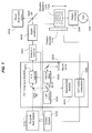
- FIG. 1 shows an example of an imaging-guided laser surgical system in which an imaging module is provided to provide imaging of a target to the laser control.
- FIGS. 2-10 show examples of imaging-guided laser surgical systems with varying degrees of integration of a laser surgical system and an imaging system.
- FIG. 11 shows an example of a method for performing laser surgery by suing an imaging-guided laser surgical system.
- FIG. 12 shows an example of an image of an eye from an optical coherence tomography (OCT) imaging module.
- OCT optical coherence tomography
- FIGS. 13A , 13 B, 13 C and 13 D show two examples of calibration samples for calibrating an imaging-guided laser surgical system.
- FIG. 14 shows an example of attaching a calibration sample material to a patient interface in an imaging-guided laser surgical system for calibrating the system.
- FIG. 15 shows an example of reference marks created by a surgical laser beam on a glass surface.
- FIGS. 16A and 16B show an example of the calibration process and the post-calibration surgical operation for an imaging-guided laser surgical system.
- FIGS. 17A and 17B show two operation modes of an exemplary imaging-guided laser surgical system that captures images of laser-induced photodisruption byproduct and the target issue to guide laser alignment.
- FIGS. 18 and 19 show examples of laser alignment operations in imaging-guided laser surgical systems.
- FIG. 20 shows an exemplary laser surgical system based on the laser alignment using the image of the photodisruption byproduct.
- Laser surgery systems can be designed to include laser control and aiming tools to precisely target laser pulses to a particular target inside the tissue.
- the required level of targeting precision is relatively low. This is in part because the laser energy used is relatively high and thus the affected tissue area is also relatively large, often covering an impacted area with a dimension in the hundreds of microns.
- the time between laser pulses in such systems tend to be long and manual controlled targeting is feasible and is commonly used.
- Such manual targeting mechanisms is a biomicroscope to visualize the target tissue in combination with a secondary laser source used as an aiming beam.
- the surgeon manually moves the focus of a laser focusing lens, usually with a joystick control, which is parfocal (with or without an offset) with their image through the microscope, so that the surgical beam or aiming beam is in best focus on the intended target.
- Examples of high repetition rate pulsed lasers for laser surgical systems include pulsed lasers at a pulse repetition rate of thousands of shots per second or higher with relatively low energy per pulse.
- Such lasers use relatively low energy per pulse to localize the tissue effect caused by laser-induced photodisruption, e.g., the impacted tissue area by photodisruption on the order of microns or tens of microns.
- This localized tissue effect can improve the precision of the laser surgery and can be desirable in certain surgical procedures such as laser eye surgery.
- placement of many hundred, thousands or millions of contiguous, nearly contiguous or pulses separated by known distances can be used to achieve certain desired surgical effects, such as tissue incisions, separations or fragmentation.
- Various surgical procedures using high repetition rate photodisruptive laser surgical systems with shorter laser pulse durations may require high precision in positioning each pulse in the target tissue under surgery both in an absolute position with respect to a target location on the target tissue and a relative position with respect to preceding pulses.
- laser pulses may be required to be delivered next to each other with an accuracy of a few microns within the time between pulses, which can be on the order of microseconds. Because the time between two sequential pulses is short and the precision requirement for the pulse alignment is high, manual targeting as used in low repetition rate pulsed laser systems may be no longer adequate or feasible.
- One technique to facilitate and control precise, high speed positioning requirement for delivery of laser pulses into the tissue is attaching a applanation plate made of a transparent material such as a glass with a predefined contact surface to the tissue so that the contact surface of the applanation plate forms a well-defined optical interface with the tissue.
- This well-defined interface can facilitate transmission and focusing of laser light into the tissue to control or reduce optical aberrations or variations (such as due to specific eye optical properties or changes that occur with surface drying) that are most critical at the air-tissue interface, which in the eye is at the anterior surface of the cornea.
- Contact lenses can be designed for various applications and targets inside the eye and other tissues, including ones that are disposable or reusable.
- the contact glass or applanation plate on the surface of the target tissue can be used as a reference plate relative to which laser pulses are focused through the adjustment of focusing elements within the laser delivery system.
- This use of a contact glass or applanation plate provides better control of the optical qualities of the tissue surface and thus allow laser pulses to be accurately placed at a high speed at a desired location (interaction point) in the target tissue relative to the applanation plate with little optical distortion of the laser pulses.
- One way for implementing an applanation plate on an eye is to use the applanation plate to provide a positional reference for delivering the laser pulses into a target tissue in the eye.
- This use of the applanation plate as a positional reference can be based on the known desired location of laser pulse focus in the target with sufficient accuracy prior to firing the laser pulses and that the relative positions of the reference plate and the individual internal tissue target must remain constant during laser firing.
- this method can require the focusing of the laser pulse to the desired location to be predictable and repeatable between eyes or in different regions within the same eye.
- the precise distance from the reference plate on the surface of the eye to the target tends to vary due to the presence of a collapsible structures, such as the cornea itself, the anterior chamber, and the iris.
- a collapsible structures such as the cornea itself, the anterior chamber, and the iris.
- structure within the eye may move due to the build-up of photodisruptive byproducts, such as cavitation bubbles.
- laser pulses delivered to the crystalline lens can cause the lens capsule to bulge forward, requiring adjustment to target this tissue for subsequent placement of laser pulses.
- it can be difficult to use computer models and simulations to predict, with sufficient accuracy, the actual location of target tissues after the applanation plate is removed and to adjust placement of laser pulses to achieve the desired localization without applanation in part because of the highly variable nature of applanation effects, which can depend on factors particular to the individual cornea or eye, and the specific surgical and applanation technique used by a surgeon.
- Photodisruption is a nonlinear optical process in the tissue material and can cause complications in beam alignment and beam targeting.
- one of the nonlinear optical effects in the tissue material when interacting with laser pulses during the photodisruption is that the refractive index of the tissue material experienced by the laser pulses is no longer a constant but varies with the intensity of the light.
- the refractive index of the tissue material also varies spatially.
- This nonlinear refractive index is self-focusing or self-defocusing in the tissue material that changes the actual focus of and shifts the position of the focus of the pulsed laser beam inside the tissue. Therefore, a precise alignment of the pulsed laser beam to each target tissue position in the target tissue may also need to account for the nonlinear optical effects of the tissue material on the laser beam.
- the use of a superficial applanation plate based on a positional reference provided by the applanation plate may be insufficient to achieve precise laser pulse localization in internal tissue targets.
- the use of the applanation plate as the reference for guiding laser delivery may require measurements of the thickness and plate position of the applanation plate with high accuracy because the deviation from nominal is directly translated into a depth precision error.
- High precision applanation lenses can be costly, especially for single use disposable applanation plates.
- the techniques, apparatus and systems described in this document can be implemented in ways that provide a targeting mechanism to deliver short laser pulses through an applanation plate to a desired localization inside the eye with precision and at a high speed without requiring the known desired location of laser pulse focus in the target with sufficient accuracy prior to firing the laser pulses and without requiring that the relative positions of the reference plate and the individual internal tissue target remain constant during laser firing.
- the present techniques, apparatus and systems can be used for various surgical procedures where physical conditions of the target tissue under surgery tend to vary and are difficult to control and the dimension of the applanation lens tends to vary from one lens to another.
- the present techniques, apparatus and systems may also be used for other surgical targets where distortion or movement of the surgical target relative to the surface of the structure is present or non-linear optical effects make precise targeting problematic.
- Examples for such surgical targets different from the eye include the heart, deeper tissue in the skin and others.
- the present techniques, apparatus and systems can be implemented in ways that maintain the benefits provided by an applanation plate, including, for example, control of the surface shape and hydration, as well as reductions in optical distortion, while providing for the precise localization of photodisruption to internal structures of the applanated surface.
- This can be accomplished through the use of an integrated imaging device to localize the target tissue relative to the focusing optics of the delivery system.
- the exact type of imaging device and method can vary and may depend on the specific nature of the target and the required level of precision.
- An applanation lens may be implemented with another mechanism to fix the eye to prevent translational and rotational movement of the eye.
- fixation devices include the use of a suction ring.
- fixation mechanism can also lead to unwanted distortion or movement of the surgical target.
- the present techniques, apparatus and systems can be implemented to provide, for high repetition rate laser surgical systems that utilize an applanation plate and/or fixation means for non-superficial surgical targets, a targeting mechanism to provide intraoperative imaging to monitor such distortion and movement of the surgical target.
- an optical imaging module to capture images of a target tissue to obtain positioning information of the target tissue, e.g., before and during a surgical procedure.
- Such obtained positioning information can be used to control the positioning and focusing of the surgical laser beam in the target tissue to provide accurate control of the placement of the surgical laser pulses in high repetition rate laser systems.
- the images obtained by the optical imaging module can be used to dynamically control the position and focus of the surgical laser beam.
- such a laser surgical system can implement an applanation plate with a flat or curved interface attaching to the target tissue to provide a controlled and stable optical interface between the target tissue and the surgical laser system and to mitigate and control optical aberrations at the tissue surface.
- FIG. 1 shows a laser surgical system based on optical imaging and applanation.
- This system includes a pulsed laser 1010 to produce a surgical laser beam 1012 of laser pulses, and an optics module 1020 to receive the surgical laser beam 1012 and to focus and direct the focused surgical laser beam 1022 onto a target tissue 1001 , such as an eye, to cause photodisruption in the target tissue 1001 .
- An applanation plate can be provided to be in contact with the target tissue 1001 to produce an interface for transmitting laser pulses to the target tissue 1001 and light coming from the target tissue 1001 through the interface.
- an optical imaging device 1030 is provided to capture light 1050 carrying target tissue images 1050 or imaging information from the target tissue 1001 to create an image of the target tissue 1001 .
- the imaging signal 1032 from the imaging device 1030 is sent to a system control module 1040 .
- the system control module 1040 operates to process the captured images from the image device 1030 and to control the optics module 1020 to adjust the position and focus of the surgical laser beam 1022 at the target tissue 101 based on information from the captured images.
- the optics module 120 can include one or more lenses and may further include one or more reflectors.
- a control actuator can be included in the optics module 1020 to adjust the focusing and the beam direction in response to a beam control signal 1044 from the system control module 1040 .
- the control module 1040 can also control the pulsed laser 1010 via a laser control signal 1042 .
- the optical imaging device 1030 may be implemented to produce an optical imaging beam that is separate from the surgical laser beam 1022 to probe the target tissue 1001 and the returned light of the optical imaging beam is captured by the optical imaging device 1030 to obtain the images of the target tissue 1001 .
- One example of such an optical imaging device 1030 is an optical coherence tomography (OCT) imaging module which uses two imaging beams, one probe beam directed to the target tissue 1001 thought the applanation plate and another reference beam in a reference optical path, to optically interfere with each other to obtain images of the target tissue 1001 .
- OCT optical coherence tomography
- the optical imaging device 1030 can use scattered or reflected light from the target tissue 1001 to capture images without sending a designated optical imaging beam to the target tissue 1001 .
- the imaging device 1030 can be a sensing array of sensing elements such as CCD or CMS sensors.
- the images of photodisruption byproduct produced by the surgical laser beam 1022 may be captured by the optical imaging device 1030 for controlling the focusing and positioning of the surgical laser beam 1022 .
- the optical imaging device 1030 captures images of the photodisruption byproduct such as the laser-induced bubbles or cavities.
- the imaging device 1030 may also be an ultrasound imaging device to capture images based on acoustic images.
- the system control module 1040 processes image data from the imaging device 1030 that includes the position offset information for the photodisruption byproduct from the target tissue position in the target tissue 1001 . Based on the information obtained from the image, the beam control signal 1044 is generated to control the optics module 1020 which adjusts the laser beam 1022 .
- a digital processing unit can be included in the system control module 1040 to perform various data processing for the laser alignment.
- the above techniques and systems can be used deliver high repetition rate laser pulses to subsurface targets with a precision required for contiguous pulse placement, as needed for cutting or volume disruption applications. This can be accomplished with or without the use of a reference source on the surface of the target and can take into account movement of the target following applanation or during placement of laser pulses.
- the applanation plate in the present systems is provided to facilitate and control precise, high speed positioning requirement for delivery of laser pulses into the tissue.
- Such an applanation plate can be made of a transparent material such as a glass with a predefined contact surface to the tissue so that the contact surface of the applanation plate forms a well-defined optical interface with the tissue.
- This well-defined interface can facilitate transmission and focusing of laser light into the tissue to control or reduce optical aberrations or variations (such as due to specific eye optical properties or changes that occur with surface drying) that are most critical at the air-tissue interface, which in the eye is at the anterior surface of the cornea.
- a number of contact lenses have been designed for various applications and targets inside the eye and other tissues, including ones that are disposable or reusable.
- the contact glass or applanation plate on the surface of the target tissue is used as a reference plate relative to which laser pulses are focused through the adjustment of focusing elements within the laser delivery system relative.
- Inherent in such an approach are the additional benefits afforded by the contact glass or applanation plate described previously, including control of the optical qualities of the tissue surface. Accordingly, laser pulses can be accurately placed at a high speed at a desired location (interaction point) in the target tissue relative to the applanation plate with little optical distortion of the laser pulses.
- the optical imaging device 1030 in FIG. 1 captures images of the target tissue 1001 via the applanation plate.
- the control module 1040 processes the captured images to extract position information from the captured images and uses the extracted position information as a position reference or guide to control the position and focus of the surgical laser beam 1022 .
- This imaging-guided laser surgery can be implemented without relying on the applanation plate as a position reference because the position of the applanation plate tends to change due to various factors as discussed above.
- the applanation plate provides a desired optical interface for the surgical laser beam to enter the target tissue and to capture images of the target tissue, it may be difficult to use the applanation plate as a position reference to align and control the position and focus of the surgical laser beam for accurate delivery of laser pulses.
- the imaging-guided control of the position and focus of the surgical laser beam based on the imaging device 1030 and the control module 1040 allows the images of the target tissue 1001 , e.g., images of inner structures of an eye, to be used as position references, without using the applanation plate to provide a position reference.
- a targeting system may be desirable for a targeting system to anticipate or account for nonlinear characteristics of photodisruption which can occur when using short pulse duration lasers.
- Photodisruption can cause complications in beam alignment and beam targeting.
- one of the nonlinear optical effects in the tissue material when interacting with laser pulses during the photodisruption is that the refractive index of the tissue material experienced by the laser pulses is no longer a constant but varies with the intensity of the light.
- the refractive index of the tissue material also varies spatially.
- This nonlinear refractive index is self-focusing or self-defocusing in the tissue material that changes the actual focus of and shifts the position of the focus of the pulsed laser beam inside the tissue. Therefore, a precise alignment of the pulsed laser beam to each target tissue position in the target tissue may also need to account for the nonlinear optical effects of the tissue material on the laser beam.
- the energy of the laser pulses may be adjusted to deliver the same physical effect in different regions of the target due to different physical characteristics, such as hardness, or due to optical considerations such as absorption or scattering of laser pulse light traveling to a particular region.
- the differences in non-linear focusing effects between pulses of different energy values can also affect the laser alignment and laser targeting of the surgical pulses.
- the direct images obtained from the target issue by the imaging device 1030 can be used to monitor the actual position of the surgical laser beam 1022 which reflects the combined effects of nonlinear optical effects in the target tissue and provide position references for control of the beam position and beam focus.
- the techniques, apparatus and systems described here can be used in combination of an applanation plate to provide control of the surface shape and hydration, to reduce optical distortion, and provide for precise localization of photodisruption to internal structures through the applanated surface.
- the imaging-guided control of the beam position and focus described here can be applied to surgical systems and procedures that use means other than applanation plates to fix the eye, including the use of a suction ring which can lead to distortion or movement of the surgical target.
- An optical or other modality imaging module such as an OCT imaging module
- An optical or other modality imaging module can be used to direct a probe light or other type of beam to capture images of a target tissue, e.g., structures inside an eye.
- a surgical laser beam of laser pulses such as femtosecond or picosecond laser pulses can be guided by position information in the captured images to control the focusing and positioning of the surgical laser beam during the surgery.
- Both the surgical laser beam and the probe light beam can be sequentially or simultaneously directed to the target tissue during the surgery so that the surgical laser beam can be controlled based on the captured images to ensure precision and accuracy of the surgery.
- imaging-guided laser surgery can be used to provide accurate and precise focusing and positioning of the surgical laser beam during the surgery because the beam control is based on images of the target tissue following applanation or fixation of the target tissue, either just before or nearly simultaneously with delivery of the surgical pulses.
- certain parameters of the target tissue such as the eye measured before the surgery may change during the surgery due to various factor such as preparation of the target tissue (e.g., fixating the eye to an applanation lens) and the alternation of the target tissue by the surgical operations. Therefore, measured parameters of the target tissue prior to such factors and/or the surgery may no longer reflect the physical conditions of the target tissue during the surgery.
- the present imaging-guided laser surgery can mitigate technical issues in connection with such changes for focusing and positioning the surgical laser beam before and during the surgery.
- the present imaging-guided laser surgery may be effectively used for accurate surgical operations inside a target tissue.
- laser light is focused inside the eye to achieve optical breakdown of the targeted tissue and such optical interactions can change the internal structure of the eye.
- the crystalline lens can change its position, shape, thickness and diameter during accommodation, not only between prior measurement and surgery but also during surgery.
- Attaching the eye to the surgical instrument by mechanical means can change the shape of the eye in a not well defined way and further, the change can vary during surgery due to various factors, e.g., patient movement.
- Attaching means include fixating the eye with a suction ring and aplanating the eye with a flat or curved lens. These changes amount to as much as a few millimeters. Mechanically referencing and fixating the surface of the eye such as the anterior surface of the cornea or limbus does not work well when performing precision laser microsurgery inside the eye.
- the post preparation or near simultaneous imaging in the present imaging-guided laser surgery can be used to establish three-dimensional positional references between the inside features of the eye and the surgical instrument in an environment where changes occur prior to and during surgery.
- the positional reference information provided by the imaging prior to applanation and/or fixation of the eye, or during the actual surgery reflects the effects of changes in the eye and thus provides an accurate guidance to focusing and positioning of the surgical laser beam.
- a system based on the present imaging-guided laser surgery can be configured to be simple in structure and cost efficient. For example, a portion of the optical components associated with guiding the surgical laser beam can be shared with optical components for guiding the probe light beam for imaging the target tissue to simplify the device structure and the optical alignment and calibration of the imaging and surgical light beams.
- the imaging-guided laser surgical systems described below use the OCT imaging as an example of an imaging instrument and other non-OCT imaging devices may also be used to capture images for controlling the surgical lasers during the surgery.
- integration of the imaging and surgical subsystems can be implemented to various degrees. In the simplest form without integrating hardware, the imaging and laser surgical subsystems are separated and can communicate to one another through interfaces. Such designs can provide flexibility in the designs of the two subsystems. Integration between the two subsystems, by some hardware components such as a patient interface, further expands the functionality by offering better registration of surgical area to the hardware components, more accurate calibration and may improve workflow. As the degree of integration between the two subsystems increases, such a system may be made increasingly cost-efficient and compact and system calibration will be further simplified and more stable over time. Examples for imaging-guided laser systems in FIGS. 2-10 are integrated at various degrees of integration.
- One implementation of a present imaging-guided laser surgical system includes a surgical laser that produces a surgical laser beam of surgical laser pulses that cause surgical changes in a target tissue under surgery; a patient interface mount that engages a patient interface in contact with the target tissue to hold the target tissue in position; and a laser beam delivery module located between the surgical laser and the patient interface and configured to direct the surgical laser beam to the target tissue through the patient interface.
- This laser beam delivery module is operable to scan the surgical laser beam in the target tissue along a predetermined surgical pattern.
- This system also includes a laser control module that controls operation of the surgical laser and controls the laser beam delivery module to produce the predetermined surgical pattern and an OCT module positioned relative to the patient interface to have a known spatial relation with respect to the patient interface and the target issue fixed to the patient interface.
- the OCT module is configured to direct an optical probe beam to the target tissue and receive returned probe light of the optical probe beam from the target tissue to capture OCT images of the target tissue while the surgical laser beam is being directed to the target tissue to perform an surgical operation so that the optical probe beam and the surgical laser beam are simultaneously present in the target tissue.
- the OCT module is in communication with the laser control module to send information of the captured OCT images to the laser control module.
- the laser control module in this particular system responds to the information of the captured OCT images to operate the laser beam delivery module in focusing and scanning of the surgical laser beam and adjusts the focusing and scanning of the surgical laser beam in the target tissue based on positioning information in the captured OCT images.
- acquiring a complete image of a target tissue may not be necessary for registering the target to the surgical instrument and it may be sufficient to acquire a portion of the target tissue, e.g., a few points from the surgical region such as natural or artificial landmarks.
- a rigid body has 6 degrees of freedom in 3D space and six independent points would be sufficient to define the rigid body.
- additional points are needed to provide the positional reference.
- several points can be used to determine the position and the curvature of the anterior and posterior surfaces, which are normally different, and the thickness and diameter of the crystalline lens of the human eye.
- a body made up from two halves of ellipsoid bodies with given parameters can approximate and visualize a crystalline lens for practical purposes.
- information from the captured image may be combined with information from other sources, such as pre-operative measurements of lens thickness that are used as an input for the controller.
- FIG. 2 shows one example of an imaging-guided laser surgical system with separated laser surgical system 2100 and imaging system 2200 .
- the laser surgical system 2100 includes a laser engine 2130 with a surgical laser that produces a surgical laser beam 2160 of surgical laser pulses.
- a laser beam delivery module 2140 is provided to direct the surgical laser beam 2160 from the laser engine 2130 to the target tissue 1001 through a patient interface 2150 and is operable to scan the surgical laser beam 2160 in the target tissue 1001 along a predetermined surgical pattern.
- a laser control module 2120 is provided to control the operation of the surgical laser in the laser engine 2130 via a communication channel 2121 and controls the laser beam delivery module 2140 via a communication channel 2122 to produce the predetermined surgical pattern.
- a patient interface mount is provided to engage the patient interface 2150 in contact with the target tissue 1001 to hold the target tissue 1001 in position.
- the patient interface 2150 can be implemented to include a contact lens or applanation lens with a flat or curved surface to conformingly engage to the anterior surface of the eye and to hold the eye in position.
- the imaging system 2200 in FIG. 2 can be an OCT module positioned relative to the patient interface 2150 of the surgical system 2100 to have a known spatial relation with respect to the patient interface 2150 and the target issue 1001 fixed to the patient interface 2150 .
- This OCT module 2200 can be configured to have its own patient interface 2240 for interacting with the target tissue 1001 .
- the imaging system 220 includes an imaging control module 2220 and an imaging sub-system 2230 .
- the sub-system 2230 includes a light source for generating imaging beam 2250 for imaging the target 1001 and an imaging beam delivery module to direct the optical probe beam or imaging beam 2250 to the target tissue 1001 and receive returned probe light 2260 of the optical imaging beam 2250 from the target tissue 1001 to capture OCT images of the target tissue 1001 .
- Both the optical imaging beam 2250 and the surgical beam 2160 can be simultaneously directed to the target tissue 1001 to allow for sequential or simultaneous imaging and surgical operation.
- communication interfaces 2110 and 2210 are provided in both the laser surgical system 2100 and the imaging system 2200 to facilitate the communications between the laser control by the laser control module 2120 and imaging by the imaging system 2200 so that the OCT module 2200 can send information of the captured OCT images to the laser control module 2120 .
- the laser control module 2120 in this system responds to the information of the captured OCT images to operate the laser beam delivery module 2140 in focusing and scanning of the surgical laser beam 2160 and dynamically adjusts the focusing and scanning of the surgical laser beam 2160 in the target tissue 1001 based on positioning information in the captured OCT images.
- the integration between the laser surgical system 2100 and the imaging system 2200 is mainly through communication between the communication interfaces 2110 and 2210 at the software level.
- various subsystems or devices may also be integrated.
- certain diagnostic instruments such as wavefront aberrometers, corneal topography measuring devices may be provided in the system, or pre-operative information from these devices can be utilized to augment intra-operative imaging.
- FIG. 3 shows an example of an imaging-guided laser surgical system with additional integration features.
- the imaging and surgical systems share a common patient interface 3300 which immobilizes target tissue 1001 (e.g., the eye) without having two separate patient interfaces as in FIG. 2 .
- the surgical beam 3210 and the imaging beam 3220 are combined at the patient interface 330 and are directed to the target 1001 by the common patient interface 3300 .
- a common control module 3100 is provided to control both the imaging sub-system 2230 and the surgical part (the laser engine 2130 and the beam delivery system 2140 ). This increased integration between imaging and surgical parts allows accurate calibration of the two subsystems and the stability of the position of the patient and surgical volume.
- a common housing 3400 is provided to enclose both the surgical and imaging subsystems. When the two systems are not integrated into a common housing, the common patient interface 3300 can be part of either the imaging or the surgical subsystem.
- FIG. 4 shows an example of an imaging-guided laser surgical system where the laser surgical system and the imaging system share both a common beam delivery module 4100 and a common patient interface 4200 . This integration further simplifies the system structure and system control operation.
- the imaging system in the above and other examples can be an optical computed tomography (OCT) system and the laser surgical system is a femtosecond or picosecond laser based ophthalmic surgical system.
- OCT optical computed tomography
- light from a low coherence, broadband light source such as a super luminescent diode is split into separate reference and signal beams.
- the signal beam is the imaging beam sent to the surgical target and the returned light of the imaging beam is collected and recombined coherently with the reference beam to form an interferometer.
- the x-y scanner of different OCT implementations are essentially the same, comparing the path lengths and getting z-scan information can happen in different ways.
- the reference arm is continuously varied to change its path length while a photodetector detects interference modulation in the intensity of the recombined beam.
- the reference arm is essentially static and the spectrum of the combined light is analyzed for interference.
- the Fourier transform of the spectrum of the combined beam provides spatial information on the scattering from the interior of the sample.
- This method is known as the spectral domain or Fourier OCT method.
- a frequency swept OCT S. R. Chinn, et. Al. Opt. Lett. 22 (1997)
- a narrowband light source is used with its frequency swept rapidly across a spectral range. Interference between the reference and signal arms is detected by a fast detector and dynamic signal analyzer.
- An external cavity tuned diode laser or frequency tuned of frequency domain mode-locked (FDML) laser developed for this purpose (R. Huber et. Al. Opt. Express, 13, 2005) (S. H. Yun, IEEE J. of Sel. Q. El. 3(4) p. 1087-1096, 1997) can be used in these examples as a light source.
- a femtosecond laser used as a light source in an OCT system can have sufficient bandwidth and can provide additional benefits of increased signal to noise ratios.
- the OCT imaging device in the systems in this document can be used to perform various imaging functions.
- the OCT can be used to suppress complex conjugates resulting from the optical configuration of the system or the presence of the applanation plate, capture OCT images of selected locations inside the target tissue to provide three-dimensional positioning information for controlling focusing and scanning of the surgical laser beam inside the target tissue, or capture OCT images of selected locations on the surface of the target tissue or on the applanation plate to provide positioning registration for controlling changes in orientation that occur with positional changes of the target, such as from upright to supine.
- the OCT can be calibrated by a positioning registration process based on placement of marks or markers in one positional orientation of the target that can then be detected by the OCT module when the target is in another positional orientation.
- the OCT imaging system can be used to produce a probe light beam that is polarized to optically gather the information on the internal structure of the eye.
- the laser beam and the probe light beam may be polarized in different polarizations.
- the OCT can include a polarization control mechanism that controls the probe light used for said optical tomography to polarize in one polarization when traveling toward the eye and in a different polarization when traveling away from the eye.
- the polarization control mechanism can include, e.g., a wave-plate or a Faraday rotator.
- the system in FIG. 4 is shown as a spectral OCT configuration and can be configured to share the focusing optics part of the beam delivery module between the surgical and the imaging systems.
- the main requirements for the optics are related to the operating wavelength, image quality, resolution, distortion etc.
- the laser surgical system can be a femtosecond laser system with a high numerical aperture system designed to achieve diffraction limited focal spot sizes, e.g., about 2 to 3 micrometers.
- Various femtosecond ophthalmic surgical lasers can operate at various wavelengths such as wavelengths of around 1.05 micrometer.
- the operating wavelength of the imaging device can be selected to be close to the laser wavelength so that the optics is chromatically compensated for both wavelengths.
- Such a system may include a third optical channel, a visual observation channel such as a surgical microscope, to provide an additional imaging device to capture images of the target tissue. If the optical path for this third optical channel shares optics with the surgical laser beam and the light of the OCT imaging device, the shared optics can be configured with chromatic compensation in the visible spectral band for the third optical channel and the spectral bands for the surgical laser beam and the OCT imaging beam.
- FIG. 5 shows a particular example of the design in FIG. 3 where the scanner 5100 for scanning the surgical laser beam and the beam conditioner 5200 for conditioning (collimating and focusing) the surgical laser beam are separate from the optics in the OCT imaging module 5300 for controlling the imaging beam for the OCT.
- the surgical and imaging systems share an objective lens 5600 module and the patient interface 3300 .
- the objective lens 5600 directs and focuses both the surgical laser beam and the imaging beam to the patient interface 3300 and its focusing is controlled by the control module 3100 .
- Two beam splitters 5410 and 5420 are provided to direct the surgical and imaging beams.
- the beam splitter 5420 is also used to direct the returned imaging beam back into the OCT imaging module 5300 .
- Two beam splitters 5410 and 5420 also direct light from the target 1001 to a visual observation optics unit 5500 to provide direct view or image of the target 1001 .
- the unit 5500 can be a lens imaging system for the surgeon to view the target 1001 or a camera to capture the image or video of the target 1001 .
- Various beam splitters can be used, such as dichroic and polarization beam splitters, optical grating, holographic beam splitter or a combinations of these devices.
- the optical components may be appropriately coated with antireflection coating for both the surgical and for the OCT wavelength to reduce glare from multiple surfaces of the optical beam path. Reflections would otherwise reduce the throughput of the system and reduce the signal to noise ratio by increasing background light in the OCT imaging unit.
- One way to reduce glare in the OCT is to rotate the polarization of the return light from the sample by wave-plate of Faraday isolator placed close to the target tissue and orient a polarizer in front of the OCT detector to preferentially detect light returned from the sample and suppress light scattered from the optical components.
- each of the surgical laser and the OCT system can have a beam scanner to cover the same surgical region in the target tissue.
- the beam scanning for the surgical laser beam and the beam scanning for the imaging beam can be integrated to share common scanning devices.
- FIG. 6 shows an example of such a system in detail.
- the x-y scanner 6410 and the z scanner 6420 are shared by both subsystems.
- a common control 6100 is provided to control the system operations for both surgical and imaging operations.
- the OCT sub-system includes an OCT light source 6200 that produce the imaging light that is split into an imaging beam and a reference beam by a beam splitter 6210 .
- the imaging beam is combined with the surgical beam at the beam splitter 6310 to propagate along a common optical path leading to the target 1001 .
- the scanners 6410 and 6420 and the beam conditioner unit 6430 are located downstream from the beam splitter 6310 .
- a beam splitter 6440 is used to direct the imaging and surgical beams to the objective lens 5600 and the patient interface 3300 .
- the reference beam transmits through the beam splitter 6210 to an optical delay device 620 and is reflected by a return mirror 6230 .
- the returned imaging beam from the target 1001 is directed back to the beam splitter 6310 which reflects at least a portion of the returned imaging beam to the beam splitter 6210 where the reflected reference beam and the returned imaging beam overlap and interfere with each other.
- a spectrometer detector 6240 is used to detect the interference and to produce OCT images of the target 1001 .
- the OCT image information is sent to the control system 6100 for controlling the surgical laser engine 2130 , the scanners 6410 and 6420 and the objective lens 5600 to control the surgical laser beam.
- the optical delay device 620 can be varied to change the optical delay to detect various depths in the target tissue 1001 .
- the two subsystems use two different z-scanners because the two scanners operate in different ways.
- the z scanner of the surgical system operates by changing the divergence of the surgical beam in the beam conditioner unit without changing the path lengths of the beam in the surgical beam path.
- the time domain OCT scans the z-direction by physically changing the beam path by a variable delay or by moving the position of the reference beam return mirror.
- the two z-scanners can be synchronized by the laser control module.
- the relationship between the two movements can be simplified to a linear or polynomial dependence, which the control module can handle or alternatively calibration points can define a look-up table to provide proper scaling.
- Spectral/Fourier domain and frequency swept source OCT devices have no z-scanner, the length of the reference arm is static. Besides reducing costs, cross calibration of the two systems will be relatively straightforward. There is no need to compensate for differences arising from image distortions in the focusing optics or from the differences of the scanners of the two systems since they are shared.
- the focusing objective lens 5600 is slidably or movably mounted on a base and the weight of the objective lens is balanced to limit the force on the patient's eye.
- the patient interface 3300 can include an applanation lens attached to a patient interface mount.
- the patient interface mount is attached to a mounting unit, which holds the focusing objective lens.
- This mounting unit is designed to ensure a stable connection between the patient interface and the system in case of unavoidable movement of the patient and allows gentler docking of the patient interface onto the eye.
- Various implementations for the focusing objective lens can be used. This presence of an adjustable focusing objective lens can change the optical path length of the optical probe light as part of the optical interferometer for the OCT sub-system.
- Movement of the objective lens 5600 and patient interface 3300 can change the path length differences between the reference beam and the imaging signal beam of the OCT in an uncontrolled way and this may degrade the OCT depth information detected by the OCT. This would happen not only in time-domain but also in spectral/Fourier domain and frequency-swept OCT systems.
- FIGS. 7 and 8 show exemplary imaging-guided laser surgical systems that address the technical issue associated with the adjustable focusing objective lens.
- the system in FIG. 7 provides a position sensing device 7110 coupled to the movable focusing objective lens 7100 to measure the position of the objective lens 7100 on a slideable mount and communicates the measured position to a control module 7200 in the OCT system.
- the control system 6100 can control and move the position of the objective lens 7100 to adjust the optical path length traveled by the imaging signal beam for the OCT operation.
- a position encoder 7110 is coupled to the objective lens 7100 and configured to measure a position change of the objective lens 7100 relative to the applanation plate and the target tissue or relative to the OCT device. The measured position of the lens 7100 is then fed to the OCT control 7200 .
- the control module 7200 in the OCT system applies an algorithm, when assembling a 3D image in processing the OCT data, to compensate for differences between the reference arm and the signal arm of the interferometer inside the OCT caused by the movement of the focusing objective lens 7100 relative to the patient interface 3300 .
- the proper amount of the change in the position of the lens 7100 computed by the OCT control module 7200 is sent to the control 6100 which controls the lens 7100 to change its position.
- FIG. 8 shows another exemplary system where the return mirror 6230 in the reference arm of the interferometer of the OCT system or at least one part in an optical path length delay assembly of the OCT system is rigidly attached to the movable focusing objective lens 7100 so the signal arm and the reference arm undergo the same amount of change in the optical path length when the objective lens 7100 moves.
- the movement of the objective lens 7100 on the slide is automatically compensated for path-length differences in the OCT system without additional need for a computational compensation.
- the laser surgical system and the OCT system use different light sources.
- a femtosecond surgical laser as a light source for the surgical laser beam can also be used as the light source for the OCT system.
- FIG. 9 shows an example where a femtosecond pulse laser in a light module 9100 is used to generate both the surgical laser beam for surgical operations and the probe light beam for OCT imaging.
- a beam splitter 9300 is provided to split the laser beam into a first beam as both the surgical laser beam and the signal beam for the OCT and a second beam as the reference beam for the OCT.
- the first beam is directed through an x-y scanner 6410 which scans the beam in the x and y directions perpendicular to the propagation direction of the first beam and a second scanner (z scanner) 6420 that changes the divergence of the beam to adjust the focusing of the first beam at the target tissue 1001 .
- This first beam performs the surgical operations at the target tissue 1001 and a portion of this first beam is back scattered to the patient interface and is collected by the objective lens as the signal beam for the signal arm of the optical interferometer of the OCT system.
- This returned light is combined with the second beam that is reflected by a return mirror 6230 in the reference arm and is delayed by an adjustable optical delay element 6220 for an time-domain OCT to control the path difference between the signal and reference beams in imaging different depths of the target tissue 1001 .
- the control system 9200 controls the system operations.
- Surgical practice on the cornea has shown that a pulse duration of several hundred femtoseconds may be sufficient to achieve good surgical performance, while for OCT of a sufficient depth resolution broader spectral bandwidth generated by shorter pulses, e.g., below several tens of femtoseconds, are needed.
- the design of the OCT device dictates the duration of the pulses from the femtosecond surgical laser.
- FIG. 10 shows another imaging-guided system that uses a single pulsed laser 9100 to produce the surgical light and the imaging light.
- a nonlinear spectral broadening media 9400 is placed in the output optical path of the femtosecond pulsed laser to use an optical non-linear process such as white light generation or spectral broadening to broaden the spectral bandwidth of the pulses from a laser source of relatively longer pulses, several hundred femtoseconds normally used in surgery.
- the media 9400 can be a fiber-optic material, for example.
- the light intensity requirements of the two systems are different and a mechanism to adjust beam intensities can be implemented to meet such requirements in the two systems.
- beam steering mirrors, beam shutters or attenuators can be provided in the optical paths of the two systems to properly control the presence and intensity of the beam when taking an OCT image or performing surgery in order to protect the patient and sensitive instruments from excessive light intensity.
- FIG. 11 shows one example of a method for performing laser surgery by using an imaging-guided laser surgical system.
- This method uses a patient interface in the system to engage to and to hold a target tissue under surgery in position and simultaneously directs a surgical laser beam of laser pulses from a laser in the system and an optical probe beam from the OCT module in the system to the patient interface into the target tissue.
- the surgical laser beam is controlled to perform laser surgery in the target tissue and the OCT module is operated to obtain OCT images inside the target tissue from light of the optical probe beam returning from the target tissue.
- the position information in the obtained OCT images is applied in focusing and scanning of the surgical laser beam to adjust the focusing and scanning of the surgical laser beam in the target tissue before or during surgery.
- FIG. 12 shows an example of an OCT image of an eye.
- the contacting surface of the applanation lens in the patient interface can be configured to have a curvature that minimizes distortions or folds in the cornea due to the pressure exerted on the eye during applanation.
- an OCT image can be obtained.
- the curvature of the lens and cornea as well as the distances between the lens and cornea are identifiable in the OCT image.
- Subtler features such as the epithelium-cornea interface are detectable. Each of these identifiable features may be used as an internal reference of the laser coordinates with the eye.
- the coordinates of the cornea and lens can be digitized using well-established computer vision algorithms such as Edge or Blob detection. Once the coordinates of the lens are established, they can be used to control the focusing and positioning of the surgical laser beam for the surgery.
- a calibration sample material may be used to form a 3-D array of reference marks at locations with known position coordinates.
- the OCT image of the calibration sample material can be obtained to establish a mapping relationship between the known position coordinates of the reference marks and the OCT images of the reference marks in the obtained OCT image.
- This mapping relationship is stored as digital calibration data and is applied in controlling the focusing and scanning of the surgical laser beam during the surgery in the target tissue based on the OCT images of the target tissue obtained during the surgery.
- the OCT imaging system is used here as an example and this calibration can be applied to images obtained via other imaging techniques.
- the surgical laser can produce relatively high peak powers sufficient to drive strong field/multi-photon ionization inside of the eye (i.e. inside of the cornea and lens) under high numerical aperture focusing. Under these conditions, one pulse from the surgical laser generates a plasma within the focal volume. Cooling of the plasma results in a well defined damage zone or “bubble” that may be used as a reference point.
- the following sections describe a calibration procedure for calibrating the surgical laser against an OCT-based imaging system using the damage zones created by the surgical laser.
- the OCT is calibrated against the surgical laser to establish a relative positioning relationship so that the surgical laser can be controlled in position at the target tissue with respect to the position associated with images in the OCT image of the target tissue obtained by the OCT.
- One way for performing this calibration uses a pre-calibrated target or “phantom” which can be damaged by the laser as well as imaged with the OCT.
- the phantom can be fabricated from various materials such as a glass or hard plastic (e.g. PMMA) such that the material can permanently record optical damage created by the surgical laser.
- the phantom can also be selected to have optical or other properties (such as water content) that are similar to the surgical target.
- the phantom can be, e.g., a cylindrical material having a diameter of at least 10 mm (or that of the scanning range of the delivery system) and a cylindrical length of at least 10 mm long spanning the distance of the epithelium to the crystalline lens of the eye, or as long as the scanning depth of the surgical system.
- the upper surface of the phantom can be curved to mate seamlessly with the patient interface or the phantom material may be compressible to allow full applanation.
- the phantom may have a three dimensional grid such that both the laser position (in x and y) and focus (z), as well as the OCT image can be referenced against the phantom.
- FIG. 13A-13D illustrate two exemplary configurations for the phantom.
- FIG. 13A illustrates a phantom that is segmented into thin disks.
- FIG. 13B shows a single disk patterned to have a grid of reference marks as a reference for determining the laser position across the phantom (i.e. the x- and y-coordinates).
- the z-coordinate (depth) can be determined by removing an individual disk from the stack and imaging it under a confocal microscope.
- FIG. 13C illustrates a phantom that can be separated into two halves. Similar to the segmented phantom in FIG. 13A , this phantom is structured to contain a grid of reference marks as a reference for determining the laser position in the x- and y-coordinates. Depth information can be extracted by separating the phantom into the two halves and measuring the distance between damage zones. The combined information can provide the parameters for image guided surgery.
- FIG. 14 shows a surgical system part of the imaging-guided laser surgical system.
- This system includes steering mirrors which may be actuated by actuators such as galvanometers or voice coils, an objective lens e and a disposable patient interface.
- the surgical laser beam is reflected from the steering mirrors through the objective lens.
- the objective lens focuses the beam just after the patient interface. Scanning in the x- and y-coordinates is performed by changing the angle of the beam relative to the objective lens. Scanning in z-plane is accomplished by changing the divergence of the incoming beam using a system of lens upstream to the steering mirrors.
- the conical section of the disposable patient interface may be either air spaced or solid and the section interfacing with the patient includes a curved contact lens.
- the curved contact lens can be fabricated from fused silica or other material resistant to forming color centers when irradiated with ionizing radiation.
- the radius of curvature is on the upper limit of what is compatible with the eye, e.g., about 10 mm.
- the first step in the calibration procedure is docking the patient interface with the phantom.
- the curvature of the phantom matches the curvature of the patient interface.
- the next step in the procedure involves creating optical damage inside of the phantom to produce the reference marks.
- FIG. 15 shows examples of actual damage zones produced by a femtosecond laser in glass.
- the separation between the damage zones is on average 8 ⁇ m (the pulse energy is 2.2 ⁇ J with duration of 580 fs at full width at half maximum).
- the optical damage depicted in FIG. 15 shows that the damage zones created by the femtosecond laser are well-defined and discrete. In the example shown, the damage zones have a diameter of about 2.5 ⁇ m.
- Optical damage zones similar to that shown in FIG. 14 are created in the phantom at various depths to form a 3-D array of the reference marks. These damage zones are referenced against the calibrated phantom either by extracting the appropriate disks and imaging it under a confocal microscope ( FIG. 13A ) or by splitting the phantom into two halves and measuring the depth using a micrometer ( FIG. 13C ).
- the x- and y-coordinates can be established from the pre-calibrated grid.
- OCT After damaging the phantom with the surgical laser, OCT on the phantom is performed.
- the OCT imaging system provides a 3D rendering of the phantom establishing a relationship between the OCT coordinate system and the phantom.
- the damage zones are detectable with the imaging system.
- the OCT and laser may be cross-calibrated using the phantom's internal standard. After the OCT and the laser are referenced against each other, the phantom can be discarded.
- the calibration Prior to surgery, the calibration can be verified. This verification step involves creating optical damage at various positions inside of a second phantom.
- the optical damage should be intense enough such that the multiple damage zones which create a circular pattern can be imaged by the OCT. After the pattern is created, the second phantom is imaged with the OCT. Comparison of the OCT image with the laser coordinates provides the final check of the system calibration prior to surgery.
- laser surgery can be performed inside the eye. This involves photo-emulsification of the lens using the laser, as well as other laser treatments to the eye.
- the surgery can be stopped at any time and the anterior segment of the eye ( FIG. 11 ) can be re-imaged to monitor the progress of the surgery; moreover, after an intraocular lens (IOL) is inserted, imaging the IOL (with light or no applanation) provides information regarding the position of the IOL in the eye. This information may be utilized by the physician to refine the position of IOL.
- IOL intraocular lens
- FIG. 16 shows an example of the calibration process and the post-calibration surgical operation.
- This examples illustrates a method for performing laser surgery by using an imaging-guided laser surgical system can include using a patient interface in the system, that is engaged to hold a target tissue under surgery in position, to hold a calibration sample material during a calibration process before performing a surgery; directing a surgical laser beam of laser pulses from a laser in the system to the patient interface into the calibration sample material to burn reference marks at selected three-dimensional reference locations; directing an optical probe beam from an optical coherence tomography (OCT) module in the system to the patient interface into the calibration sample material to capture OCT images of the burnt reference marks; and establishing a relationship between positioning coordinates of the OCT module and the burnt reference marks.
- OCT optical coherence tomography
- a patient interface in the system is used to engage to and to hold a target tissue under surgery in position.
- the surgical laser beam of laser pulses and the optical probe beam are directed to the patient interface into the target tissue.
- the surgical laser beam is controlled to perform laser surgery in the target tissue.
- the OCT module is operated to obtain OCT images inside the target tissue from light of the optical probe beam returning from the target tissue and the position information in the obtained OCT images and the established relationship are applied in focusing and scanning of the surgical laser beam to adjust the focusing and scanning of the surgical laser beam in the target tissue during surgery. While such calibrations can be performed immediately prior to laser surgery, they can also be performed at various intervals before a procedure, using calibration validations that demonstrated a lack of drift or change in calibration during such intervals.
- the following examples describe imaging-guided laser surgical techniques and systems that use images of laser-induced photodisruption byproducts for alignment of the surgical laser beam.
- FIGS. 17A and 17B illustrates another implementation of the present technique in which actual photodisruption byproducts in the target tissue are used to guide further laser placement.
- a pulsed laser 1710 such as a femtosecond or picosecond laser, is used to produce a laser beam 1712 with laser pulses to cause photodisruption in a target tissue 1001 .
- the target tissue 1001 may be a part of a body part 1700 of a subject, e.g., a portion of the lens of one eye.
- the laser beam 1712 is focused and directed by an optics module for the laser 1710 to a target tissue position in the target tissue 1001 to achieve a certain surgical effect.
- the target surface is optically coupled to the laser optics module by an applanation plate 1730 that transmits the laser wavelength, as well as image wavelengths from the target tissue.
- the applanation plate 1730 can be an applanation lens.
- An imaging device 1720 is provided to collect reflected or scattered light or sound from the target tissue 1001 to capture images of the target tissue 1001 either before or after (or both) the applanation plate is applied.
- the captured imaging data is then processed by the laser system control module to determine the desired target tissue position.
- the laser system control module moves or adjusts optical or laser elements based on standard optical models to ensure that the center of photodisruption byproduct 1702 overlaps with the target tissue position. This can be a dynamic alignment process where the images of the photodisruption byproduct 1702 and the target tissue 1001 are continuously monitored during the surgical process to ensure that the laser beam is properly positioned at each target tissue position.
- the laser system can be operated in two modes: first in a diagnostic mode in which the laser beam 1712 is initially aligned by using alignment laser pulses to create photodisruption byproduct 1702 for alignment and then in a surgical mode where surgical laser pulses are generated to perform the actual surgical operation. In both modes, the images of the disruption byproduct 1702 and the target tissue 1001 are monitored to control the beam alignment.
- FIG. 17A shows the diagnostic mode where the alignment laser pulses in the laser beam 1712 may be set at a different energy level than the energy level of the surgical laser pulses.
- the alignment laser pulses may be less energetic than the surgical laser pulses but sufficient to cause significant photodisruption in the tissue to capture the photodisruption byproduct 1702 at the imaging device 1720 .
- the resolution of this coarse targeting may not be sufficient to provide desired surgical effect.
- the laser beam 1712 can be aligned properly. After this initial alignment, the laser 1710 can be controlled to produce the surgical laser pulses at a higher energy level to perform the surgery. Because the surgical laser pulses are at a different energy level than the alignment laser pulses, the nonlinear effects in the tissue material in the photodisruption can cause the laser beam 1712 to be focused at a different position from the beam position during the diagnostic mode.
- the alignment achieved during the diagnostic mode is a coarse alignment and additional alignment can be further performed to precisely position each surgical laser pulse during the surgical mode when the surgical laser pulses perform the actual surgery.
- the imaging device 1720 captures the images from the target tissue 1001 during the surgical mode and the laser control module adjust the laser beam 1712 to place the focus position 1714 of the laser beam 1712 onto the desired target tissue position in the target tissue 1001 . This process is performed for each target tissue position.
- FIG. 18 shows one implementation of the laser alignment where the laser beam is first approximately aimed at the target tissue and then the image of the photodisruption byproduct is captured and used to align the laser beam.
- the image of the target tissue of the body part as the target tissue and the image of a reference on the body part are monitored to aim the pulsed laser beam at the target tissue.
- the images of photodisruption byproduct and the target tissue are used to adjust the pulsed laser beam to overlap the location of the photodisruption byproduct with the target tissue.
- FIG. 19 shows one implementation of the laser alignment method based on imaging photodisruption byproduct in the target tissue in laser surgery.
- a pulsed laser beam is aimed at a target tissue location within target tissue to deliver a sequence of initial alignment laser pulses to the target tissue location.
- the images of the target tissue location and photodisruption byproduct caused by the initial alignment laser pulses are monitored to obtain a location of the photodisruption byproduct relative to the target tissue location.
- the location of photodisruption byproduct caused by surgical laser pulses at a surgical pulse energy level different from the initial alignment laser pulses is determined when the pulsed laser beam of the surgical laser pulses is placed at the target tissue location.
- the pulsed laser beam is controlled to carry surgical laser pulses at the surgical pulse energy level.
- the position of the pulsed laser beam is adjusted at the surgical pulse energy level to place the location of photodisruption byproduct at the determined location. While monitoring images of the target tissue and the photodisruption byproduct, the position of the pulsed laser beam at the surgical pulse energy level is adjusted to place the location of photodisruption byproduct at a respective determined location when moving the pulsed laser beam to a new target tissue location within the target tissue.
- FIG. 20 shows an exemplary laser surgical system based on the laser alignment using the image of the photodisruption byproduct.
- An optics module 2010 is provided to focus and direct the laser beam to the target tissue 1700 .
- the optics module 2010 can include one or more lenses and may further include one or more reflectors.
- a control actuator is included in the optics module 2010 to adjust the focusing and the beam direction in response to a beam control signal.
- a system control module 2020 is provided to control both the pulsed laser 1010 via a laser control signal and the optics module 2010 via the beam control signal.
- the system control module 2020 processes image data from the imaging device 2030 that includes the position offset information for the photodisruption byproduct 1702 from the target tissue position in the target tissue 1700 . Based on the information obtained from the image, the beam control signal is generated to control the optics module 2010 which adjusts the laser beam.
- a digital processing unit is included in the system control module 2020 to perform various data processing for the laser alignment.
- the imaging device 2030 can be implemented in various forms, including an optical coherent tomography (OCT) device.
- OCT optical coherent tomography
- an ultrasound imaging device can also be used.
- the position of the laser focus is moved so as to place it grossly located at the target at the resolution of the imaging device.
- the error in the referencing of the laser focus to the target and possible non-linear optical effects such as self focusing that make it difficult to accurately predict the location of the laser focus and subsequent photodisruption event.
- Various calibration methods including the use of a model system or software program to predict focusing of the laser inside a material can be used to get a coarse targeting of the laser within the imaged tissue.
- the imaging of the target can be performed both before and after the photodisruption.
- the position of the photodisruption by products relative to the target is used to shift the focal point of the laser to better localize the laser focus and photodisruption process at or relative to the target.
- the actual photodisruption event is used to provide a precise targeting for the placement of subsequent surgical pulses.
- Photodisruption for targeting during the diagnostic mode can be performed at a lower, higher or the same energy level that is required for the later surgical processing in the surgical mode of the system.
- a calibration may be used to correlate the localization of the photodisruptive event performed at a different energy in diagnostic mode with the predicted localization at the surgical energy because the optical pulse energy level can affect the exact location of the photodisruptive event.
- a volume or pattern of laser pulses (or a single pulse) can be delivered relative to this positioning. Additional sampling images can be made during the course of delivering the additional laser pulses to ensure proper localization of the laser (the sampling images may be obtained with use of lower, higher or the same energy pulses).
- an ultrasound device is used to detect the cavitation bubble or shock wave or other photodisruption byproduct. The localization of this can then be correlated with imaging of the target, obtained via ultrasound or other modality.
- the imaging device is simply a biomicroscope or other optical visualization of the photodisruption event by the operator, such as optical coherence tomography. With the initial observation, the laser focus is moved to the desired target position, after which a pattern or volume of pulses is delivered relative to this initial position.
- a laser system for precise subsurface photodisruption can include means for generating laser pulses capable of generating photodisruption at repetition rates of 100-1000 Million pulses per second, means for coarsely focusing laser pulses to a target below a surface using an image of the target and a calibration of the laser focus to that image without creating a surgical effect, means for detecting or visualizing below a surface to provide an image or visualization of a target the adjacent space or material around the target and the byproducts of at least one photodisruptive event coarsely localized near the target, means for correlating the position of the byproducts of photodisruption with that of the sub surface target at least once and moving the focus of the laser pulse to position the byproducts of photodisruption at the sub surface target or at a relative position relative to the target, means for delivering a subsequent train of at least one additional laser pulse in pattern relative to the position indicated by the above fine correlation of the byproducts of photodisruption with that of the sub surface
- the above techniques and systems can be used deliver high repetition rate laser pulses to subsurface targets with a precision required for contiguous pulse placement, as needed for cutting or volume disruption applications. This can be accomplished with or without the use of a reference source on the surface of the target and can take into account movement of the target following applanation or during placement of laser pulses.
- imaging-guided laser surgical techniques, apparatus and systems are disclosed. However, variations and enhancements of the described implementations, and other implementations can be made based on what is described.
Abstract
Description
Claims (13)
Priority Applications (2)
| Application Number | Priority Date | Filing Date | Title |
|---|---|---|---|
| US14/138,170 US9044303B2 (en) | 2007-09-06 | 2013-12-23 | Precise targeting of surgical photodisruption |
| US14/701,190 US9408749B2 (en) | 2007-09-06 | 2015-04-30 | Precise targeting of surgical photodisruption |
Applications Claiming Priority (3)
| Application Number | Priority Date | Filing Date | Title |
|---|---|---|---|
| US97047707P | 2007-09-06 | 2007-09-06 | |
| US12/205,844 US8764737B2 (en) | 2007-09-06 | 2008-09-05 | Precise targeting of surgical photodisruption |
| US14/138,170 US9044303B2 (en) | 2007-09-06 | 2013-12-23 | Precise targeting of surgical photodisruption |
Related Parent Applications (1)
| Application Number | Title | Priority Date | Filing Date |
|---|---|---|---|
| US12/205,844 Continuation US8764737B2 (en) | 2007-09-06 | 2008-09-05 | Precise targeting of surgical photodisruption |
Related Child Applications (1)
| Application Number | Title | Priority Date | Filing Date |
|---|---|---|---|
| US14/701,190 Continuation US9408749B2 (en) | 2007-09-06 | 2015-04-30 | Precise targeting of surgical photodisruption |
Publications (2)
| Publication Number | Publication Date |
|---|---|
| US20140188093A1 US20140188093A1 (en) | 2014-07-03 |
| US9044303B2 true US9044303B2 (en) | 2015-06-02 |
Family
ID=40429728
Family Applications (3)
| Application Number | Title | Priority Date | Filing Date |
|---|---|---|---|
| US12/205,844 Active 2032-04-19 US8764737B2 (en) | 2007-09-06 | 2008-09-05 | Precise targeting of surgical photodisruption |
| US14/138,170 Active US9044303B2 (en) | 2007-09-06 | 2013-12-23 | Precise targeting of surgical photodisruption |
| US14/701,190 Active US9408749B2 (en) | 2007-09-06 | 2015-04-30 | Precise targeting of surgical photodisruption |
Family Applications Before (1)
| Application Number | Title | Priority Date | Filing Date |
|---|---|---|---|
| US12/205,844 Active 2032-04-19 US8764737B2 (en) | 2007-09-06 | 2008-09-05 | Precise targeting of surgical photodisruption |
Family Applications After (1)
| Application Number | Title | Priority Date | Filing Date |
|---|---|---|---|
| US14/701,190 Active US9408749B2 (en) | 2007-09-06 | 2015-04-30 | Precise targeting of surgical photodisruption |
Country Status (6)
| Country | Link |
|---|---|
| US (3) | US8764737B2 (en) |
| EP (2) | EP2826436B1 (en) |
| JP (4) | JP2010538700A (en) |
| DE (1) | DE112008002383T5 (en) |
| ES (2) | ES2655204T3 (en) |
| WO (1) | WO2009033111A2 (en) |
Cited By (11)
| Publication number | Priority date | Publication date | Assignee | Title |
|---|---|---|---|---|
| JP2016190047A (en) * | 2007-09-06 | 2016-11-10 | アルコン レンゼックス, インコーポレーテッド | Laser surgery systems |
| WO2018025169A1 (en) | 2016-08-01 | 2018-02-08 | Novartis Ag | Integrated ophthalmic surgical system |
| US20180092694A1 (en) * | 2015-05-20 | 2018-04-05 | Zwxg (Beijing) Technology Co., Ltd | Visual fractional laser instrument |
| US10821024B2 (en) | 2018-07-16 | 2020-11-03 | Vialase, Inc. | System and method for angled optical access to the irido-corneal angle of the eye |
| US10821023B2 (en) | 2018-07-16 | 2020-11-03 | Vialase, Inc. | Integrated surgical system and method for treatment in the irido-corneal angle of the eye |
| US11064884B2 (en) | 2017-01-19 | 2021-07-20 | Alcon Inc. | Method and apparatus for optical coherence tomography scanning |
| US11110006B2 (en) | 2018-09-07 | 2021-09-07 | Vialase, Inc. | Non-invasive and minimally invasive laser surgery for the reduction of intraocular pressure in the eye |
| US11173067B2 (en) | 2018-09-07 | 2021-11-16 | Vialase, Inc. | Surgical system and procedure for precise intraocular pressure reduction |
| US11246754B2 (en) | 2018-07-16 | 2022-02-15 | Vialase, Inc. | Surgical system and procedure for treatment of the trabecular meshwork and Schlemm's canal using a femtosecond laser |
| US11564567B2 (en) | 2020-02-04 | 2023-01-31 | Vialase, Inc. | System and method for locating a surface of ocular tissue for glaucoma surgery based on dual aiming beams |
| US11612315B2 (en) | 2020-04-09 | 2023-03-28 | Vialase, Inc. | Alignment and diagnostic device and methods for imaging and surgery at the irido-corneal angle of the eye |
Families Citing this family (115)
| Publication number | Priority date | Publication date | Assignee | Title |
|---|---|---|---|---|
| US8679089B2 (en) | 2001-05-21 | 2014-03-25 | Michael S. Berlin | Glaucoma surgery methods and systems |
| US9603741B2 (en) | 2000-05-19 | 2017-03-28 | Michael S. Berlin | Delivery system and method of use for the eye |
| CA2446143C (en) | 2000-05-19 | 2010-01-19 | Michael S. Berlin | Delivery system and method of use for the eye |
| US9375349B2 (en) | 2006-01-20 | 2016-06-28 | Lensar, Llc | System and method for providing laser shot patterns to the lens of an eye |
| US10842675B2 (en) | 2006-01-20 | 2020-11-24 | Lensar, Inc. | System and method for treating the structure of the human lens with a laser |
| US9889043B2 (en) | 2006-01-20 | 2018-02-13 | Lensar, Inc. | System and apparatus for delivering a laser beam to the lens of an eye |
| US9545338B2 (en) | 2006-01-20 | 2017-01-17 | Lensar, Llc. | System and method for improving the accommodative amplitude and increasing the refractive power of the human lens with a laser |
| US8262646B2 (en) * | 2006-01-20 | 2012-09-11 | Lensar, Inc. | System and method for providing the shaped structural weakening of the human lens with a laser |
| CN101631522B (en) | 2007-03-13 | 2014-11-05 | 眼科医疗公司 | Apparatus for creating ocular surgical and relaxing incisions |
| US20170360609A9 (en) | 2007-09-24 | 2017-12-21 | Ivantis, Inc. | Methods and devices for increasing aqueous humor outflow |
| AU2009221859B2 (en) | 2008-03-05 | 2013-04-18 | Alcon Inc. | Methods and apparatus for treating glaucoma |
| ES2644492T3 (en) * | 2008-04-11 | 2017-11-29 | Wavelight Gmbh | System for refractive ophthalmic surgery |
| US8500723B2 (en) | 2008-07-25 | 2013-08-06 | Lensar, Inc. | Liquid filled index matching device for ophthalmic laser procedures |
| US8480659B2 (en) | 2008-07-25 | 2013-07-09 | Lensar, Inc. | Method and system for removal and replacement of lens material from the lens of an eye |
| KR20150008512A (en) * | 2009-04-01 | 2015-01-22 | 웨이브라이트 게엠베하 | Device for the laser radiation treatment of an eye |
| US8900221B2 (en) | 2009-04-01 | 2014-12-02 | Wavelight Gmbh | Apparatus for treating an eye with laser radiation |
| WO2010129544A1 (en) * | 2009-05-04 | 2010-11-11 | Duke University | Methods and computer program products for quantitative three-dimensional image correction and clinical parameter computation in optical coherence tomography |
| JP5306269B2 (en) | 2009-06-25 | 2013-10-02 | キヤノン株式会社 | Imaging apparatus and imaging method using optical coherence tomography |
| US8933837B2 (en) | 2009-07-02 | 2015-01-13 | Univeristy Of Manitoba | Imaging system and method using spatially separated radiated fields |
| CN102481404B (en) | 2009-07-09 | 2014-03-05 | 伊万提斯公司 | Ocular implants |
| AU2010271274B2 (en) | 2009-07-09 | 2015-05-21 | Alcon Inc. | Single operator device for delivering an ocular implant |
| AU2010275380A1 (en) | 2009-07-24 | 2012-02-16 | Lensar, Inc. | System and method for performing ladar assisted procedures on the lens of an eye |
| US8382745B2 (en) | 2009-07-24 | 2013-02-26 | Lensar, Inc. | Laser system and method for astigmatic corrections in association with cataract treatment |
| US8617146B2 (en) | 2009-07-24 | 2013-12-31 | Lensar, Inc. | Laser system and method for correction of induced astigmatism |
| US8758332B2 (en) | 2009-07-24 | 2014-06-24 | Lensar, Inc. | Laser system and method for performing and sealing corneal incisions in the eye |
| AU2010281495B2 (en) * | 2009-07-29 | 2015-01-15 | Alcon Inc. | Optical system with multiple scanners for ophthalmic surgical laser |
| RU2546405C2 (en) * | 2009-07-29 | 2015-04-10 | Алькон Ленскс, Инк. | Optical system for ophthalmic surgical laser |
| US8262647B2 (en) * | 2009-07-29 | 2012-09-11 | Alcon Lensx, Inc. | Optical system for ophthalmic surgical laser |
| CN102612353B (en) * | 2009-07-29 | 2015-10-07 | 爱尔康蓝斯克斯股份有限公司 | For the optical system of ophthalmic surgical laser |
| US8267925B2 (en) * | 2009-07-29 | 2012-09-18 | Alcon Lensx, Inc. | Optical system for ophthalmic surgical laser |
| RU2012107531A (en) * | 2009-07-29 | 2013-09-10 | Алькон Ленскс, Инк. | OPTICAL SYSTEM FOR OPHTHALMIC SURGICAL LASER |
| MX2012001324A (en) * | 2009-07-29 | 2012-08-15 | Alcon Lensx Inc | Optical system for ophthalmic surgical laser. |
| MX2012001330A (en) * | 2009-07-29 | 2012-08-15 | Alcon Lensx Inc | Optical system for ophthalmic surgical laser. |
| US9504608B2 (en) | 2009-07-29 | 2016-11-29 | Alcon Lensx, Inc. | Optical system with movable lens for ophthalmic surgical laser |
| US8419721B2 (en) * | 2009-07-29 | 2013-04-16 | Alcon Lensx, Inc. | Optical system for ophthalmic surgical laser |
| AU2010281512A1 (en) * | 2009-07-29 | 2012-02-16 | Alcon Lensx, Inc. | Optical system for ophthalmic surgical laser |
| US8696653B2 (en) * | 2009-10-02 | 2014-04-15 | Cardiofocus, Inc. | Cardiac ablation system with pulsed aiming light |
| US9492322B2 (en) * | 2009-11-16 | 2016-11-15 | Alcon Lensx, Inc. | Imaging surgical target tissue by nonlinear scanning |
| US8506559B2 (en) * | 2009-11-16 | 2013-08-13 | Alcon Lensx, Inc. | Variable stage optical system for ophthalmic surgical laser |
| KR101441100B1 (en) * | 2009-12-07 | 2014-09-22 | 웨이브라이트 게엠베하 | Device for ophthalmic laser surgery |
| CN102843955A (en) | 2010-02-01 | 2012-12-26 | 雷萨公司 | Purkinjie image-based alignment of suction ring in ophthalmic applications |
| US8265364B2 (en) * | 2010-02-05 | 2012-09-11 | Alcon Lensx, Inc. | Gradient search integrated with local imaging in laser surgical systems |
| US8414564B2 (en) * | 2010-02-18 | 2013-04-09 | Alcon Lensx, Inc. | Optical coherence tomographic system for ophthalmic surgery |
| US8398236B2 (en) | 2010-06-14 | 2013-03-19 | Alcon Lensx, Inc. | Image-guided docking for ophthalmic surgical systems |
| JP5610884B2 (en) | 2010-07-09 | 2014-10-22 | キヤノン株式会社 | Optical tomographic imaging apparatus and optical tomographic imaging method |
| US9532708B2 (en) | 2010-09-17 | 2017-01-03 | Alcon Lensx, Inc. | Electronically controlled fixation light for ophthalmic imaging systems |
| USD694890S1 (en) | 2010-10-15 | 2013-12-03 | Lensar, Inc. | Laser system for treatment of the eye |
| USD695408S1 (en) | 2010-10-15 | 2013-12-10 | Lensar, Inc. | Laser system for treatment of the eye |
| CN106974614B (en) | 2010-10-15 | 2019-04-26 | 雷萨公司 | The system and method for the scan control illumination of the structure of inside of eye |
| WO2012100030A2 (en) * | 2011-01-19 | 2012-07-26 | Duke University | Imaging and visualization systems, instruments, and methods using optical coherence tomography |
| WO2012135073A2 (en) * | 2011-03-25 | 2012-10-04 | Board Of Trustees Of Michigan State University | Adaptive laser system for ophthalmic use |
| US10463541B2 (en) | 2011-03-25 | 2019-11-05 | Lensar, Inc. | System and method for correcting astigmatism using multiple paired arcuate laser generated corneal incisions |
| US8459794B2 (en) | 2011-05-02 | 2013-06-11 | Alcon Lensx, Inc. | Image-processor-controlled misalignment-reduction for ophthalmic systems |
| US20120283557A1 (en) | 2011-05-05 | 2012-11-08 | Berlin Michael S | Methods and Apparatuses for the Treatment of Glaucoma using visible and infrared ultrashort laser pulses |
| DE102011075799A1 (en) | 2011-05-13 | 2012-11-15 | Carl Zeiss Meditec Ag | Optical system for a laser therapy device |
| US9622913B2 (en) | 2011-05-18 | 2017-04-18 | Alcon Lensx, Inc. | Imaging-controlled laser surgical system |
| US8657776B2 (en) | 2011-06-14 | 2014-02-25 | Ivantis, Inc. | Ocular implants for delivery into the eye |
| US9521949B2 (en) | 2011-06-23 | 2016-12-20 | Amo Development, Llc | Ophthalmic range finding |
| EP3001944B1 (en) * | 2011-06-23 | 2021-11-03 | AMO Development, LLC | Ophthalmic range finding |
| US8398238B1 (en) | 2011-08-26 | 2013-03-19 | Alcon Lensx, Inc. | Imaging-based guidance system for ophthalmic docking using a location-orientation analysis |
| DE102011116760A1 (en) | 2011-10-20 | 2013-04-25 | Carl Zeiss Meditec Ag | Ophthalmic laser system and method for the laser surgical treatment of the cornea |
| US9023016B2 (en) | 2011-12-19 | 2015-05-05 | Alcon Lensx, Inc. | Image processor for intra-surgical optical coherence tomographic imaging of laser cataract procedures |
| US9066784B2 (en) | 2011-12-19 | 2015-06-30 | Alcon Lensx, Inc. | Intra-surgical optical coherence tomographic imaging of cataract procedures |
| US8663150B2 (en) | 2011-12-19 | 2014-03-04 | Ivantis, Inc. | Delivering ocular implants into the eye |
| JP5988772B2 (en) | 2012-01-20 | 2016-09-07 | キヤノン株式会社 | Image processing apparatus and image processing method |
| JP2013148509A (en) | 2012-01-20 | 2013-08-01 | Canon Inc | Image processing device and image processing method |
| JP6061554B2 (en) | 2012-01-20 | 2017-01-18 | キヤノン株式会社 | Image processing apparatus and image processing method |
| JP6039185B2 (en) | 2012-01-20 | 2016-12-07 | キヤノン株式会社 | Imaging device |
| JP5936368B2 (en) * | 2012-01-20 | 2016-06-22 | キヤノン株式会社 | Optical coherence tomography apparatus and method for operating the same |
| JP6146951B2 (en) | 2012-01-20 | 2017-06-14 | キヤノン株式会社 | Image processing apparatus, image processing method, photographing apparatus, and photographing method |
| US8807752B2 (en) | 2012-03-08 | 2014-08-19 | Technolas Perfect Vision Gmbh | System and method with refractive corrections for controlled placement of a laser beam's focal point |
| US8852177B2 (en) | 2012-03-09 | 2014-10-07 | Alcon Lensx, Inc. | Spatio-temporal beam modulator for surgical laser systems |
| US10182943B2 (en) | 2012-03-09 | 2019-01-22 | Alcon Lensx, Inc. | Adjustable pupil system for surgical laser systems |
| US9358156B2 (en) | 2012-04-18 | 2016-06-07 | Invantis, Inc. | Ocular implants for delivery into an anterior chamber of the eye |
| JP6024218B2 (en) * | 2012-06-02 | 2016-11-09 | 株式会社ニデック | Ophthalmic laser surgery device |
| US10617558B2 (en) | 2012-11-28 | 2020-04-14 | Ivantis, Inc. | Apparatus for delivering ocular implants into an anterior chamber of the eye |
| KR101371384B1 (en) * | 2013-01-10 | 2014-03-07 | 경북대학교 산학협력단 | Tracking system and method for tracking using the same |
| CA2904761A1 (en) * | 2013-03-13 | 2014-10-09 | Amo Development, Llc | Ophthalmic range finding |
| US10568764B2 (en) * | 2013-03-14 | 2020-02-25 | Amo Development, Llc | System and methods for depth detection in laser-assisted ophthalmic procedures |
| CA2906298C (en) * | 2013-03-15 | 2021-05-25 | Amo Development, Llc | Systems and methods for providing anatomical flap centration for an ophthalmic laser treatment system |
| US10285757B2 (en) * | 2013-03-15 | 2019-05-14 | Cynosure, Llc | Picosecond optical radiation systems and methods of use |
| US11433254B2 (en) * | 2013-03-15 | 2022-09-06 | Pavel V. Efremkin | Apparatus and method for treatment of wounds and skin medical conditions at a predetermined skin area |
| JP6271927B2 (en) * | 2013-09-18 | 2018-01-31 | 株式会社トプコン | Laser treatment system |
| DE102013219829A1 (en) | 2013-09-30 | 2015-04-02 | Carl Zeiss Ag | Method and system for adjusting a laser treatment system on the eye |
| EP2913036A1 (en) | 2014-02-28 | 2015-09-02 | Nidek co., Ltd. | Ophthalmic laser surgery apparatus, and eyeball fixing portion movement unit and eyeball fixing unit used in the same |
| US10420608B2 (en) * | 2014-05-20 | 2019-09-24 | Verily Life Sciences Llc | System for laser ablation surgery |
| WO2016011056A1 (en) | 2014-07-14 | 2016-01-21 | Ivantis, Inc. | Ocular implant delivery system and method |
| US20160022484A1 (en) * | 2014-07-25 | 2016-01-28 | Novartis Ag | Optical coherence tomography-augmented surgical instruments and systems and methods for correcting undesired movement of surgical instruments |
| DE112015004692A5 (en) | 2014-10-17 | 2017-07-13 | Carl Zeiss Meditec Ag | Systems and methods for short-pulse laser eye surgery |
| WO2016127140A1 (en) | 2015-02-05 | 2016-08-11 | Duke University | Compact telescope configurations for light scanning systems and methods of using the same |
| US10238279B2 (en) | 2015-02-06 | 2019-03-26 | Duke University | Stereoscopic display systems and methods for displaying surgical data and information in a surgical microscope |
| DE102015002726A1 (en) | 2015-02-27 | 2016-09-01 | Carl Zeiss Meditec Ag | Ophthalmic laser therapy device and method for calibration |
| DE102015205696A1 (en) * | 2015-03-30 | 2016-10-06 | Carl Zeiss Meditec Ag | Ophthalmic laser therapy device |
| JP2016214781A (en) | 2015-05-26 | 2016-12-22 | ソニー株式会社 | Surgery system, image processing device, and method |
| CN108135470B (en) | 2015-08-14 | 2021-03-09 | 伊万提斯公司 | Ocular implant with pressure sensor and delivery system |
| WO2017070473A1 (en) * | 2015-10-21 | 2017-04-27 | Optimedica Corporation | Laser beam calibration and beam quality measurement in laser surgery systems |
| WO2017106517A1 (en) | 2015-12-15 | 2017-06-22 | Ivantis, Inc. | Ocular implant and delivery system |
| JP6836098B2 (en) * | 2015-12-29 | 2021-02-24 | 株式会社ニデック | Laser treatment device for ophthalmology |
| US10219948B2 (en) | 2016-02-24 | 2019-03-05 | Perfect Ip, Llc | Ophthalmic laser treatment system and method |
| DE102016107225A1 (en) | 2016-04-19 | 2017-10-19 | Carl Zeiss Meditec Ag | Method and system for eye observation and therapy, in particular apparatus for laser-assisted cataract surgery |
| US10694939B2 (en) | 2016-04-29 | 2020-06-30 | Duke University | Whole eye optical coherence tomography(OCT) imaging systems and related methods |
| DE102017107915A1 (en) | 2016-07-18 | 2018-01-18 | Carl Zeiss Meditec Ag | System for eye therapy by tissue treatment by nonlinear interaction |
| DE102017107926A1 (en) | 2016-07-18 | 2018-01-18 | Carl Zeiss Meditec Ag | System for eye observation and therapy, in particular apparatus for laser-assisted eye surgery |
| EP3281598A1 (en) * | 2016-08-09 | 2018-02-14 | Koninklijke Philips N.V. | Light based skin treatment device and method |
| US11642168B2 (en) | 2016-12-28 | 2023-05-09 | Koninklijke Philips N.V. | Light based skin treatment device |
| DE102017103999A1 (en) * | 2017-02-27 | 2018-08-30 | Carl Zeiss Meditec Ag | Patient interface and method for ensuring the sterility of the patient interface |
| JP6786424B2 (en) * | 2017-03-13 | 2020-11-18 | 株式会社モリタ製作所 | 3D scanner |
| JP6500071B2 (en) * | 2017-10-16 | 2019-04-10 | 株式会社トプコン | Laser treatment system |
| AU2018384025A1 (en) | 2017-12-12 | 2020-04-23 | Alcon Inc. | Combined near infrared imaging and visible imaging in a compact microscope stack |
| TWI691700B (en) * | 2018-07-18 | 2020-04-21 | 薩摩亞商銳準醫光股份有限公司 | Optical slice device using advanced optical interference microscopy |
| FR3086164A1 (en) * | 2018-09-20 | 2020-03-27 | Keranova | METHOD AND DEVICE FOR DETERMINING A MINIMUM LASER ENERGY VALUE NECESSARY TO FORM A GAS BUBBLE |
| US20220211436A1 (en) * | 2019-05-14 | 2022-07-07 | Board Of Regents, The University Of Texas System | Methods and apparatus for high-speed and high-aspect ratio laser subtractive material processing |
| US20210290286A1 (en) * | 2020-03-18 | 2021-09-23 | Bolt Medical, Inc. | Optical analyzer assembly and method for intravascular lithotripsy device |
| EP4157171A1 (en) * | 2020-05-24 | 2023-04-05 | Carl Zeiss Meditec AG | System for laser-based ametropia correction, and method for the alignment thereof |
| EP4274529A1 (en) | 2021-01-11 | 2023-11-15 | Alcon Inc. | Systems and methods for viscoelastic delivery |
Citations (261)
| Publication number | Priority date | Publication date | Assignee | Title |
|---|---|---|---|---|
| US4164222A (en) | 1976-07-12 | 1979-08-14 | Fizichesky Institut Imeni P.N. Lebedeva Akademii Nauk SSSU of USSR | Laser ophthalmological unit |
| US4198143A (en) | 1977-02-18 | 1980-04-15 | Tokyo Kogaku Kikai Kabushiki Kaisha | Apparatus for taking photographs of sections of crystalline lenses in which line focusing moves lens in its own plane |
| US4235529A (en) | 1977-02-21 | 1980-11-25 | Tokyo Kogaku Kikai Kabushiki Kaisha | Apparatus for recording images of crystalline lens sections |
| US4465348A (en) | 1980-11-29 | 1984-08-14 | Carl-Zeiss-Stiftung | Apparatus for the subjective and objective determination of refraction |
| US4520816A (en) | 1983-01-12 | 1985-06-04 | Schachar Ronald A | Method and apparatus for delivering laser energy for ophthalmic use |
| US4533222A (en) | 1979-10-25 | 1985-08-06 | Canon Kabushiki Kaisha | Eye examining instrument |
| US4538608A (en) | 1984-03-23 | 1985-09-03 | Esperance Jr Francis A L | Method and apparatus for removing cataractous lens tissue by laser radiation |
| US4554917A (en) | 1982-04-01 | 1985-11-26 | Essilor International Cie Generale D'optique | Laser ophthalmological surgical device |
| US4635299A (en) | 1985-06-11 | 1987-01-06 | United States Of America As Represented By The Secretary Of The Air Force | Discrete phase conjugate technique for precompensation of laser beams transmitted through turbulence |
| US4638801A (en) | 1983-07-06 | 1987-01-27 | Lasers For Medicine | Laser ophthalmic surgical system |
| US4764005A (en) | 1985-09-17 | 1988-08-16 | Eye Research Institute Of Retina Foundation | Double scanning optical apparatus |
| EP0326760A2 (en) | 1988-02-02 | 1989-08-09 | Intelligent Surgical Lasers | Laser beam guidance apparatus |
| US4881808A (en) | 1988-02-10 | 1989-11-21 | Intelligent Surgical Lasers | Imaging system for surgical lasers |
| US4907586A (en) | 1988-03-31 | 1990-03-13 | Intelligent Surgical Lasers | Method for reshaping the eye |
| WO1990009141A2 (en) | 1989-02-06 | 1990-08-23 | Phoenix Laser Systems, Inc. | Method and apparatus for precision laser surgery |
| US5048946A (en) | 1990-05-15 | 1991-09-17 | Phoenix Laser Systems, Inc. | Spectral division of reflected light in complex optical diagnostic and therapeutic systems |
| US5049147A (en) | 1989-04-06 | 1991-09-17 | Danon Nissim N | Apparatus for computerized laser surgery |
| US5054907A (en) | 1989-12-22 | 1991-10-08 | Phoenix Laser Systems, Inc. | Ophthalmic diagnostic apparatus and method |
| US5112328A (en) | 1988-01-25 | 1992-05-12 | Refractive Laser Research & Development Program, Ltd. | Method and apparatus for laser surgery |
| US5139022A (en) | 1990-10-26 | 1992-08-18 | Philip Lempert | Method and apparatus for imaging and analysis of ocular tissue |
| US5246435A (en) | 1992-02-25 | 1993-09-21 | Intelligent Surgical Lasers | Method for removing cataractous material |
| US5255025A (en) | 1991-10-15 | 1993-10-19 | Volk Donald A | Measurement apparatus for indirect ophthalmoscopy |
| US5286964A (en) | 1991-02-19 | 1994-02-15 | Phoenix Laser Systems, Inc. | System for detecting, correcting and measuring depth movement of a target |
| US5321501A (en) | 1991-04-29 | 1994-06-14 | Massachusetts Institute Of Technology | Method and apparatus for optical imaging with means for controlling the longitudinal range of the sample |
| US5336215A (en) | 1993-01-22 | 1994-08-09 | Intelligent Surgical Lasers | Eye stabilizing mechanism for use in ophthalmic laser surgery |
| US5391165A (en) | 1990-08-22 | 1995-02-21 | Phoenix Laser Systems, Inc. | System for scanning a surgical laser beam |
| US5439462A (en) | 1992-02-25 | 1995-08-08 | Intelligent Surgical Lasers | Apparatus for removing cataractous material |
| US5493109A (en) | 1994-08-18 | 1996-02-20 | Carl Zeiss, Inc. | Optical coherence tomography assisted ophthalmologic surgical microscope |
| US5541951A (en) | 1994-11-14 | 1996-07-30 | Intelligent Surgical Lasers, Inc. | Device and method for high-power end pumping |
| US5548234A (en) | 1994-12-21 | 1996-08-20 | Intelligent Surgical Lasers, Inc. | System and method for control of a Pockel's cell |
| US5549632A (en) | 1992-10-26 | 1996-08-27 | Novatec Laser Systems, Inc. | Method and apparatus for ophthalmic surgery |
| US5561678A (en) | 1995-05-02 | 1996-10-01 | Intelligent Surgical Lasers | Time-sharing laser |
| US5656186A (en) | 1994-04-08 | 1997-08-12 | The Regents Of The University Of Michigan | Method for controlling configuration of laser induced breakdown and ablation |
| WO1998008048A1 (en) | 1996-08-23 | 1998-02-26 | Medjet Inc. | Topographical cornea mapping for corneal vision correction |
| US5738676A (en) | 1995-01-03 | 1998-04-14 | Hammer; Daniel X. | Laser surgical probe for use in intraocular surgery |
| US5779696A (en) | 1990-07-23 | 1998-07-14 | Sunrise Technologies International, Inc. | Method and apparatus for performing corneal reshaping to correct ocular refractive errors |
| US5789734A (en) | 1993-05-14 | 1998-08-04 | Canon Kabushiki Kaisha | Exposure apparatus that compensates for spherical aberration of an image forming device |
| US5795295A (en) | 1996-06-25 | 1998-08-18 | Carl Zeiss, Inc. | OCT-assisted surgical microscope with multi-coordinate manipulator |
| WO1998056298A1 (en) | 1997-06-11 | 1998-12-17 | Endius Incorporated | Surgical instrument |
| US5936706A (en) | 1997-08-21 | 1999-08-10 | Kabushiki Kaisha Topcon | Ophthalmic instrument |
| US5954711A (en) | 1993-12-28 | 1999-09-21 | Nidek Co., Ltd. | Laser treatment apparatus |
| US5954648A (en) | 1996-04-29 | 1999-09-21 | U.S. Philips Corporation | Image guided surgery system |
| US5994690A (en) | 1997-03-17 | 1999-11-30 | Kulkarni; Manish D. | Image enhancement in optical coherence tomography using deconvolution |
| US6004314A (en) | 1994-08-18 | 1999-12-21 | Carl Zeiss, Inc. | Optical coherence tomography assisted surgical apparatus |
| US6081543A (en) | 1998-05-14 | 2000-06-27 | The Regents Of The University Of Michigan | Stretcher-compressor assembly having a single grating |
| US6095648A (en) | 1998-03-09 | 2000-08-01 | Herbert Schwind Gmbh & Co. Kg | Process and arrangement for examining a section of the eye |
| US6099522A (en) | 1989-02-06 | 2000-08-08 | Visx Inc. | Automated laser workstation for high precision surgical and industrial interventions |
| US6137585A (en) | 1998-05-15 | 2000-10-24 | Laser Diagnostic Technologies, Inc. | Method and apparatus for recording three-dimensional distribution of light backscattering potential in transparent and semi-transparent structures |
| US6203539B1 (en) | 1993-05-07 | 2001-03-20 | Visx, Incorporated | Method and system for laser treatment of refractive errors using offset imaging |
| US6220707B1 (en) | 2000-02-25 | 2001-04-24 | 20/10 Perfect Vision Optische Geraete Gmbh | Method for programming an active mirror to mimic a wavefront |
| US6254595B1 (en) | 1998-10-15 | 2001-07-03 | Intralase Corporation | Corneal aplanation device |
| US20010022648A1 (en) | 1998-04-27 | 2001-09-20 | Ming Lai | Optical tracking based on a change in optical reflection across a reference mark on an object to be tracked |
| US6314311B1 (en) | 1999-07-28 | 2001-11-06 | Picker International, Inc. | Movable mirror laser registration system |
| US6317616B1 (en) | 1999-09-15 | 2001-11-13 | Neil David Glossop | Method and system to facilitate image guided surgery |
| US6324191B1 (en) | 2000-01-12 | 2001-11-27 | Intralase Corp. | Oscillator with mode control |
| US6337925B1 (en) | 2000-05-08 | 2002-01-08 | Adobe Systems Incorporated | Method for determining a border in a complex scene with applications to image masking |
| US20020013574A1 (en) | 1997-04-30 | 2002-01-31 | Jens Elbrecht | Method and arrangement for phacoemulsification |
| US6377349B1 (en) | 1998-03-30 | 2002-04-23 | Carl Zeiss Jena Gmbh | Arrangement for spectral interferometric optical tomography and surface profile measurement |
| US6379005B1 (en) | 1996-12-23 | 2002-04-30 | University Of Rochester | Method and apparatus for improving vision and the resolution of retinal images |
| US20020082466A1 (en) | 2000-12-22 | 2002-06-27 | Jeongho Han | Laser surgical system with light source and video scope |
| US20020097374A1 (en) | 2000-06-28 | 2002-07-25 | Peter Alfred Payne | Ophthalmic uses of lasers |
| US6451009B1 (en) | 2000-09-12 | 2002-09-17 | The Regents Of The University Of California | OCDR guided laser ablation device |
| US20020133145A1 (en) | 2001-01-11 | 2002-09-19 | Mario Gerlach | Laser slit lamp with laser radiation source |
| US6454761B1 (en) | 1995-01-30 | 2002-09-24 | Philip D. Freedman | Laser surgery device and method |
| JP2002345758A (en) | 2001-05-25 | 2002-12-03 | Canon Inc | Ophthalmic imaging device |
| US6497701B2 (en) | 1999-04-30 | 2002-12-24 | Visx, Incorporated | Method and system for ablating surfaces with partially overlapping craters having consistent curvature |
| WO2003002008A1 (en) | 2001-06-29 | 2003-01-09 | Intralase Corp. | Improved applanation lens and method for ophthalmic surgical applications |
| US6529758B2 (en) | 1996-06-28 | 2003-03-04 | The Board Of Trustees Of The Leland Stanford Junior University | Method and apparatus for volumetric image navigation |
| US20030053219A1 (en) | 2001-07-30 | 2003-03-20 | Manzi David J. | Lens system and method |
| US20030090674A1 (en) | 1996-12-04 | 2003-05-15 | Iosif Zeylikovich | System and method for performing selected optical measurements |
| US6579282B2 (en) | 2001-04-25 | 2003-06-17 | 20/10 Perfect Vision Optische Geraete Gmbh | Device and method for creating a corneal reference for an eyetracker |
| WO2003062802A2 (en) | 2002-01-24 | 2003-07-31 | The General Hospital Corporation | Apparatus and method for rangings and noise reduction of low coherence interferometry lci and optical coherence tomography (oct) signals by parallel detection of spectral bands |
| US6610051B2 (en) | 2001-10-12 | 2003-08-26 | 20/10 Perfect Vision Optische Geraete Gmbh | Device and method for performing refractive surgery |
| US6610050B2 (en) | 2001-07-27 | 2003-08-26 | 20/10 Perfect Vision, Optische Geraete Gmbh | Laser beam delivery system with multiple focal points |
| US6623476B2 (en) | 1998-10-15 | 2003-09-23 | Intralase Corp. | Device and method for reducing corneal induced aberrations during ophthalmic laser surgery |
| US20030206272A1 (en) | 2000-07-14 | 2003-11-06 | Cornsweet Tom N. | Ocular fundus auto imager |
| US6687010B1 (en) | 1999-09-09 | 2004-02-03 | Olympus Corporation | Rapid depth scanning optical imaging device |
| US6693927B1 (en) | 2002-09-13 | 2004-02-17 | Intralase Corp. | Method and apparatus for oscillator start-up control for mode-locked laser |
| US20040039378A1 (en) | 2000-06-01 | 2004-02-26 | Lin Charles P. | Selective photocoagulation |
| US6730074B2 (en) | 2002-05-24 | 2004-05-04 | 20/10 Perfect Vision Optische Geraete Gmbh | Cornea contact system for laser surgery |
| US6741359B2 (en) | 2002-05-22 | 2004-05-25 | Carl Zeiss Meditec, Inc. | Optical coherence tomography optical scanner |
| US6746121B2 (en) | 2001-04-27 | 2004-06-08 | Denwood F. Ross | Defocus and astigmatism compensation in a wavefront aberration measurement system |
| WO2004049228A1 (en) | 2002-11-26 | 2004-06-10 | Mikhail Anatolievich Rogov | Method for forming risk management contracts by means of a computer system |
| US6751033B2 (en) | 2001-10-12 | 2004-06-15 | Intralase Corp. | Closed-loop focal positioning system and method |
| US6755819B1 (en) | 1999-09-10 | 2004-06-29 | Haag-Streit Ag | Method and device for the photoablation of the cornea with a laser beam |
| US6763259B1 (en) | 1999-07-02 | 2004-07-13 | Carl-Zeiss-Stiftung (De) | Surgical system supported by optical coherence tomography |
| US6769769B2 (en) | 2002-06-28 | 2004-08-03 | Oti Ophthalmic Technologies Inc. | Optical mapping apparatus with adjustable depth resolution and multiple functionality |
| US20040151466A1 (en) | 2003-01-24 | 2004-08-05 | Janet Crossman-Bosworth | Optical beam scanning system for compact image display or image acquisition |
| US6775007B2 (en) | 2001-01-29 | 2004-08-10 | Joseph A. Izatt | Frequency-encoded parallel OCT and associated systems and methods |
| EP1444946A1 (en) | 2001-11-15 | 2004-08-11 | Kabushiki Kaisha TOPCON | Ophthalmologic apparatus and ophthalmologic chart |
| DE10307741A1 (en) | 2003-02-24 | 2004-09-02 | Carl Zeiss Meditec Ag | Arrangement for improving the image field in ophthalmic devices |
| US20040202351A1 (en) | 2003-01-11 | 2004-10-14 | Samsung Electronics Co., Ltd. | Mobile robot, and system and method for autnomous navigation of the same |
| US20040243233A1 (en) | 2002-03-05 | 2004-12-02 | Phillips Andrew F. | Method of implanting an accommodating intraocular lens |
| US20040243112A1 (en) | 2003-06-02 | 2004-12-02 | Mark Bendett | Apparatus and method for ophthalmologic surgical procedures using a femtosecond fiber laser |
| US20040254568A1 (en) | 2003-06-10 | 2004-12-16 | Sie Ag Surgical Instrument Engineering | Ophthalmological apparatus for the breakdown of eye tissue |
| US20050010109A1 (en) | 2003-03-27 | 2005-01-13 | Ivan Faul | Means of tracking movement of bodies during medical treatment |
| US20050015120A1 (en) | 2003-07-11 | 2005-01-20 | Seibel Eric J. | Scanning laser device and methods of use |
| US20050021011A1 (en) | 1999-07-23 | 2005-01-27 | Lahaye Leon C. | Method and apparatus for monitoring laser surgery |
| US6863667B2 (en) | 2001-01-29 | 2005-03-08 | Intralase Corp. | Ocular fixation and stabilization device for ophthalmic surgical applications |
| US6887232B2 (en) | 2002-11-13 | 2005-05-03 | 20/10 Perfect Vision Optische Geraete Gmbh | Closed loop control for intrastromal wavefront-guided ablation |
| US6908196B2 (en) | 2000-10-20 | 2005-06-21 | Wavefront Sciences, Inc. | System and method for performing optical corrective procedures with real-time feedback |
| US6932807B1 (en) | 1999-09-01 | 2005-08-23 | Nidek Co., Ltd. | Laser treatment apparatus |
| US20050192562A1 (en) | 2004-03-01 | 2005-09-01 | Frieder Loesel | System and method for positioning a patient for laser surgery |
| US20050201633A1 (en) | 2004-03-11 | 2005-09-15 | Daeyang Foundation | Method, medium, and filter removing a blocking effect |
| US20050203492A1 (en) | 2003-12-23 | 2005-09-15 | Nguyen Phuoc K. | Method and system for patient optical fixation |
| US20050215986A1 (en) | 2004-03-24 | 2005-09-29 | Visx, Inc. | Calibrating laser beam position and shape using an image capture device |
| EP1584310A1 (en) | 2004-04-09 | 2005-10-12 | 20/10 Perfect Vision Optische Geräte GmbH | Beam steering system for corneal laser surgery |
| US20050274894A1 (en) | 2004-06-14 | 2005-12-15 | Fujinon Corporation | Tomography imaging apparatus |
| US20050288745A1 (en) | 2004-06-28 | 2005-12-29 | Andersen Dan E | Method and device for optical ophthalmic therapy |
| US20050284774A1 (en) | 2004-06-24 | 2005-12-29 | Mordaunt David H | Ophthalmic lens assembly utilizing replaceable contact element |
| US20050286019A1 (en) | 2004-06-10 | 2005-12-29 | Wiltberger Michael W | Scanning ophthalmic fixation method and apparatus |
| US20060020172A1 (en) | 2004-07-21 | 2006-01-26 | Rowiak Gmbh. | OCT laryngoscope |
| US6992765B2 (en) | 2002-10-11 | 2006-01-31 | Intralase Corp. | Method and system for determining the alignment of a surface of a material in relation to a laser beam |
| US6996905B2 (en) | 2002-10-28 | 2006-02-14 | Soqi Kabushiki Kaisha | Method of making gear pump |
| US7006232B2 (en) | 2002-04-05 | 2006-02-28 | Case Western Reserve University | Phase-referenced doppler optical coherence tomography |
| US7027233B2 (en) | 2001-10-12 | 2006-04-11 | Intralase Corp. | Closed-loop focal positioning system and method |
| US20060077346A1 (en) | 2004-09-24 | 2006-04-13 | Kazuhiro Matsumoto | Ophthalmic image sensing apparatus |
| US20060084954A1 (en) | 2004-08-17 | 2006-04-20 | Intralase Corp. | Apparatus and method for correction of abberations in laser system optics |
| US20060100613A1 (en) | 2004-11-02 | 2006-05-11 | Mcardle George J | Apparatus and processes for preventing or delaying one or more symptoms of presbyopia |
| US7061622B2 (en) | 2001-08-03 | 2006-06-13 | Case Western Reserve University | Aspects of basic OCT engine technologies for high speed optical coherence tomography and light source and other improvements in optical coherence tomography |
| US7072047B2 (en) | 2002-07-12 | 2006-07-04 | Case Western Reserve University | Method and system for quantitative image correction for optical coherence tomography |
| WO2006074469A2 (en) | 2005-01-10 | 2006-07-13 | Optimedica Corporation | Method and apparatus for patterned plasma-mediated laser trephination of the lens capsule and three dimensional phaco-segmentation |
| US7079254B2 (en) | 2003-03-26 | 2006-07-18 | Southwest Sciences Incorporated | Method and apparatus for imaging internal structures of transparent and translucent materials |
| US20060179992A1 (en) | 2003-01-04 | 2006-08-17 | Omid Kermani | Microtome |
| US20060187462A1 (en) | 2005-01-21 | 2006-08-24 | Vivek Srinivasan | Methods and apparatus for optical coherence tomography scanning |
| US7102756B2 (en) | 1998-09-11 | 2006-09-05 | University Hospitals Of Cleveland | Interferometers for optical coherence tomography and reflectometry |
| US20060206102A1 (en) | 2002-06-27 | 2006-09-14 | Visx, Incorporated | Integrated Scanning and Ocular Tomography System and Method |
| US7113818B2 (en) | 2002-04-08 | 2006-09-26 | Oti Ophthalmic Technologies Inc. | Apparatus for high resolution imaging of moving organs |
| DE102005013949A1 (en) | 2005-03-26 | 2006-09-28 | Carl Zeiss Meditec Ag | scanning device |
| US7126693B2 (en) | 2004-03-29 | 2006-10-24 | Carl Zeiss Meditec, Inc. | Simple high efficiency optical coherence domain reflectometer design |
| US7130054B2 (en) | 2001-10-18 | 2006-10-31 | Scimed Life Systems, Inc. | Diffraction grating based interferometric systems and methods |
| US7139077B2 (en) | 2003-05-19 | 2006-11-21 | Oti Ophthalmic Technologies Inc. | Optical mapping apparatus with optimized OCT configuration |
| US7145661B2 (en) | 2003-12-31 | 2006-12-05 | Carl Zeiss Meditec, Inc. | Efficient optical coherence tomography (OCT) system and method for rapid imaging in three dimensions |
| US7148970B2 (en) | 2001-10-16 | 2006-12-12 | The General Hospital Corporation | Systems and methods for imaging a sample |
| US20070013867A1 (en) | 2004-10-21 | 2007-01-18 | Nidek Co., Ltd. | Fundus camera |
| WO2007021022A1 (en) | 2005-08-16 | 2007-02-22 | Ohara Inc. | Structure and manufacturing method of the same |
| US7184148B2 (en) | 2004-05-14 | 2007-02-27 | Medeikon Corporation | Low coherence interferometry utilizing phase |
| US7207983B2 (en) | 2005-04-29 | 2007-04-24 | University Of Florida Research Foundation, Inc. | System and method for real-time feedback of ablation rate during laser refractive surgery |
| US20070106285A1 (en) | 2005-11-09 | 2007-05-10 | Ferenc Raksi | Laser scanner |
| US20070121069A1 (en) | 2005-11-16 | 2007-05-31 | Andersen Dan E | Multiple spot photomedical treatment using a laser indirect ophthalmoscope |
| US20070129775A1 (en) | 2005-09-19 | 2007-06-07 | Mordaunt David H | System and method for generating treatment patterns |
| US20070126985A1 (en) | 2005-10-28 | 2007-06-07 | Wiltberger Michael W | Photomedical treatment system and method with a virtual aiming device |
| US20070129709A1 (en) | 2005-12-01 | 2007-06-07 | Andersen Dan E | System and method for minimally traumatic ophthalmic photomedicine |
| US20070147730A1 (en) | 2005-09-19 | 2007-06-28 | Wiltberger Michael W | Optical switch and method for treatment of tissue |
| JP2007159740A (en) | 2005-12-12 | 2007-06-28 | Nidek Co Ltd | Laser treatment apparatus for ophthalmology |
| US7248371B2 (en) | 2004-03-30 | 2007-07-24 | Kabushiki Kaisha Topcon | Optical image measuring apparatus |
| US20070173791A1 (en) | 2006-01-20 | 2007-07-26 | Intralase Corp. | System for ophthalmic laser surgery |
| US20070173796A1 (en) | 2006-01-25 | 2007-07-26 | Ralf Kessler | Device and method for calibrating a laser system |
| WO2007084694A2 (en) | 2006-01-20 | 2007-07-26 | Lensar, Inc. | System and apparatus for delivering a laser beam to the lens of an eye |
| US20070173795A1 (en) | 2006-01-20 | 2007-07-26 | Frey Rudolph W | System and apparatus for treating the lens of an eye |
| US20070185475A1 (en) | 2006-01-20 | 2007-08-09 | Frey Rudolph W | System and method for providing the shaped structural weakening of the human lens with a laser |
| US20070189664A1 (en) | 2006-01-12 | 2007-08-16 | Andersen Dan E | Optical delivery systems and methods of providing adjustable beam diameter, spot size and/or spot shape |
| US7268885B2 (en) | 2004-03-16 | 2007-09-11 | Kabushiki Kaisha Topcon | Optical image measuring apparatus for forming an image of an object to be measured based on interference light |
| US20070216909A1 (en) | 2006-03-16 | 2007-09-20 | Everett Matthew J | Methods for mapping tissue with optical coherence tomography data |
| US20070219541A1 (en) | 2006-03-14 | 2007-09-20 | Intralase Corp. | System and method for ophthalmic laser surgery on a cornea |
| EP1837696A1 (en) | 2006-03-20 | 2007-09-26 | WaveLight AG | Optical imaging system and method for controlling and using such an imaging system |
| US20070230520A1 (en) | 2002-10-17 | 2007-10-04 | Lumenis Inc. | System, Method, and Apparatus to Provide Laser Beams of Two or More Wavelengths |
| US7280221B2 (en) | 2004-02-10 | 2007-10-09 | Optovue, Inc. | High efficiency low coherence interferometry |
| US20070235543A1 (en) | 2006-04-07 | 2007-10-11 | Intralase Corp. | Adaptive pattern correction for laser scanners |
| WO2007130411A2 (en) | 2006-05-01 | 2007-11-15 | Physical Sciences, Inc. | Hybrid spectral domain optical coherence tomography line scanning laser ophthalmoscope |
| US20070282313A1 (en) | 2006-06-01 | 2007-12-06 | University Of Southern California | Method and apparatus to guide laser corneal surgery with optical measurement |
| US7307733B2 (en) | 2004-08-03 | 2007-12-11 | Kabushiki Kaisha Topeon | Optical image measuring apparatus and optical image measuring method |
| US7310150B2 (en) | 2002-01-11 | 2007-12-18 | The General Hospital Corporation | Apparatus and method for low coherence ranging |
| US20070291277A1 (en) | 2006-06-20 | 2007-12-20 | Everett Matthew J | Spectral domain optical coherence tomography system |
| US7312876B2 (en) | 2004-10-14 | 2007-12-25 | Kabushiki Kaisha Topcon | Optical image measuring apparatus |
| US20070299429A1 (en) | 2004-12-01 | 2007-12-27 | Nidek Co., Ltd. | Ophthalmic Apparatus |
| US7319566B2 (en) | 2003-05-28 | 2008-01-15 | Agilent Technologies, Inc. | Beam manipulation using sets of wedges |
| US20080015553A1 (en) | 2006-07-12 | 2008-01-17 | Jaime Zacharias | Steering laser treatment system and method of use |
| US20080033406A1 (en) | 2006-04-28 | 2008-02-07 | Dan Andersen | Dynamic optical surgical system utilizing a fixed relationship between target tissue visualization and beam delivery |
| US7330270B2 (en) | 2005-01-21 | 2008-02-12 | Carl Zeiss Meditec, Inc. | Method to suppress artifacts in frequency-domain optical coherence tomography |
| US7329002B2 (en) | 2004-02-03 | 2008-02-12 | Nidek Co., Ltd. | Ophthalmic apparatus |
| US7330273B2 (en) | 2004-02-14 | 2008-02-12 | Oti Ophthalmic Technologies Inc. | Compact high resolution imaging apparatus |
| US7336366B2 (en) | 2005-01-20 | 2008-02-26 | Duke University | Methods and systems for reducing complex conjugate ambiguity in interferometric data |
| US7335223B2 (en) | 2003-01-30 | 2008-02-26 | Carl-Zeiss-Stiftung | Apparatus for the treatment of body tissue |
| US20080055543A1 (en) | 2006-08-29 | 2008-03-06 | Scott Meyer | Image adjustment derived from optical imaging measurement data |
| US20080056610A1 (en) | 2005-01-31 | 2008-03-06 | Yamato Kanda | Image Processor, Microscope System, and Area Specifying Program |
| US7342659B2 (en) | 2005-01-21 | 2008-03-11 | Carl Zeiss Meditec, Inc. | Cross-dispersed spectrometer in a spectral domain optical coherence tomography system |
| US20080071254A1 (en) | 2001-01-29 | 2008-03-20 | Advanced Medical Optics, Inc. | Ophthalmic interface apparatus and system and method of interfacing a surgical laser with an eye |
| US7347548B2 (en) | 2003-05-01 | 2008-03-25 | The Cleveland Clinic Foundation | Method and apparatus for measuring a retinal sublayer characteristic |
| US20080077121A1 (en) | 2006-09-07 | 2008-03-27 | Sie Ag Surgical Instrument Engineering | Ophthalmological apparatus for the refractive correction of an eye |
| US7352444B1 (en) | 2004-06-24 | 2008-04-01 | Cypress Semiconductor Corp. | Method for arranging and rotating a semiconductor wafer within a photolithography tool prior to exposing the wafer |
| US7355716B2 (en) | 2002-01-24 | 2008-04-08 | The General Hospital Corporation | Apparatus and method for ranging and noise reduction of low coherence interferometry LCI and optical coherence tomography OCT signals by parallel detection of spectral bands |
| US20080088795A1 (en) | 2006-04-11 | 2008-04-17 | Goldstein Lee E | Ocular imaging |
| US7365856B2 (en) | 2005-01-21 | 2008-04-29 | Carl Zeiss Meditec, Inc. | Method of motion correction in optical coherence tomography imaging |
| US7365859B2 (en) | 2004-09-10 | 2008-04-29 | The General Hospital Corporation | System and method for optical coherence imaging |
| US7364296B2 (en) | 2002-06-12 | 2008-04-29 | University Of Rochester | Method and apparatus for improving both lateral and axial resolution in ophthalmoscopy |
| US20080100612A1 (en) | 2006-10-27 | 2008-05-01 | Dastmalchi Shahram S | User interface for efficiently displaying relevant oct imaging data |
| US7372578B2 (en) | 2004-09-15 | 2008-05-13 | Kabushiki Kaisha Topcon | Optical image measuring apparatus |
| US7370966B2 (en) | 2006-04-07 | 2008-05-13 | Kabushiki Kaisha Topcon | Opthalmologic apparatus |
| WO2008055506A2 (en) | 2006-11-10 | 2008-05-15 | Lars Michael Larsen | Apparatus for non or minimally disruptive photomanipulation of an eye |
| US7388672B2 (en) | 2004-11-19 | 2008-06-17 | Carl Ziess Meditec, Inc. | High efficiency balanced detection interferometer |
| US20080147052A1 (en) | 2003-06-02 | 2008-06-19 | Carl Zeiss Meditec Ag | Method and apparatus for precision working of material |
| US7390089B2 (en) | 2005-02-25 | 2008-06-24 | 20/10 Perfect Vision Optische Geraete Gmbh | Device and method for aligning an eye with a surgical laser |
| US20080167642A1 (en) | 2006-11-10 | 2008-07-10 | Palanker Daniel V | System And Method For Determining Dosimetry In Ophthalmic Photomedicine |
| US7400410B2 (en) | 2005-10-05 | 2008-07-15 | Carl Zeiss Meditec, Inc. | Optical coherence tomography for eye-length measurement |
| US20080192783A1 (en) | 2006-07-21 | 2008-08-14 | Sie Ag Surgical Instrument Engineering | Ophthalmological device |
| US20080228176A1 (en) | 2006-07-04 | 2008-09-18 | Wavelight Ag | Eye-Contact Element |
| US20080231807A1 (en) | 2004-01-22 | 2008-09-25 | Centre National De La Recherche Scientifqes | High Resolution Laterial and Axial Tomography |
| US7433046B2 (en) | 2004-09-03 | 2008-10-07 | Carl Ziess Meditec, Inc. | Patterned spinning disk based optical phase shifter for spectral domain optical coherence tomography |
| US20080269731A1 (en) | 2003-11-19 | 2008-10-30 | Casimir Andrew Swinger | Method and apparatus applying patient-verified prescription of high order aberrations |
| US20080281413A1 (en) | 2007-03-13 | 2008-11-13 | William Culbertson | Method and apparatus for creating incisions to improve intraocular lens placement |
| US7461658B2 (en) | 2005-04-26 | 2008-12-09 | Biolase Technology, Inc. | Methods for treating eye conditions |
| US7466423B2 (en) | 2005-08-26 | 2008-12-16 | University Of Kent | Optical mapping apparatus |
| US20080319427A1 (en) | 2007-03-13 | 2008-12-25 | Palanker Daniel V | Computer guided patterned laser trabeculoplasty |
| US20080319464A1 (en) | 2007-04-26 | 2008-12-25 | Carl Zeiss Meditec Ag | Re-treatment for ophthalmic correction of refraction |
| US20080319428A1 (en) | 2006-11-10 | 2008-12-25 | Carl Zeiss Meditec Ag | Treatment apparatus for surgical correction of defective eyesight, method of generating control data therefore, and method for surgical correction of defective eyesight |
| US7470025B2 (en) | 2004-12-21 | 2008-12-30 | Canon Kabushiki Kaisha | Ophthalmic apparatus |
| US20090002835A1 (en) | 2007-06-28 | 2009-01-01 | Silicon Optix Inc. | Method for lens performance optimization using electronic aberration correction |
| US7477764B2 (en) | 2002-11-13 | 2009-01-13 | Carl Zeiss Surgical Gmbh | Examination system and examination method |
| US7480058B2 (en) | 2006-01-19 | 2009-01-20 | Optovue, Inc. | Fourier-domain optical coherence tomography imager |
| US7488930B2 (en) | 2006-06-02 | 2009-02-10 | Medeikon Corporation | Multi-channel low coherence interferometer |
| US7488070B2 (en) | 2003-12-22 | 2009-02-10 | Carl Zeiss Ag | Optical measuring system and optical measuring method |
| US7492466B2 (en) | 2004-10-13 | 2009-02-17 | Kabushiki Kaisha Topcon | Optical image measuring apparatus and optical image measuring method |
| US20090088734A1 (en) | 2007-09-28 | 2009-04-02 | Eos Holdings, Llc | Laser-assisted thermal separation of tissue |
| US7522642B2 (en) | 2006-03-29 | 2009-04-21 | Amo Development Llc | Method and system for laser amplification using a dual crystal Pockels cell |
| US20090118718A1 (en) | 2007-11-07 | 2009-05-07 | Intralase, Inc. | System and method for incising material |
| US20090125005A1 (en) | 2002-02-11 | 2009-05-14 | Amo Manufacturing Usa, Llc | Closed Loop System and Method for Ablating Lenses with Aberrations |
| US20090131921A1 (en) | 2007-09-06 | 2009-05-21 | Lensx Lasers, Inc. | Precise Targeting of Surgical Photodisruption |
| US7537591B2 (en) | 2000-05-17 | 2009-05-26 | Carl Zeiss Meditec Ag | Method and device for monitoring the energy and/or the position of a pulsed and scanned laser beam |
| US20090149742A1 (en) | 2007-12-11 | 2009-06-11 | Tomey Corporation | Apparatus and method for imaging anterior eye part by optical coherence tomography |
| US20090149841A1 (en) | 2007-09-10 | 2009-06-11 | Kurtz Ronald M | Effective Laser Photodisruptive Surgery in a Gravity Field |
| US20090157062A1 (en) | 2007-12-13 | 2009-06-18 | Christoph Hauger | Systems and methods for treating glaucoma and systems and methods for imaging a portion of an eye |
| US20090161827A1 (en) | 2007-12-23 | 2009-06-25 | Oraya Therapeutics, Inc. | Methods and devices for detecting, controlling, and predicting radiation delivery |
| US20090168017A1 (en) | 2007-12-26 | 2009-07-02 | O'hara Keith E | Refractive prescription using optical coherence tomography |
| US20090171327A1 (en) | 2007-09-06 | 2009-07-02 | Lensx Lasers, Inc. | Photodisruptive Laser Treatment of the Crystalline Lens |
| US7557928B2 (en) | 2005-11-30 | 2009-07-07 | Nidek Co., Ltd. | Apparatus using optical coherence tomography based on spectral interference, and an ophthalmic apparatus |
| US20090177189A1 (en) | 2008-01-09 | 2009-07-09 | Ferenc Raksi | Photodisruptive laser fragmentation of tissue |
| US7575322B2 (en) | 2007-05-11 | 2009-08-18 | Amo Development Llc. | Auto-alignment and auto-focus system and method |
| US20090231704A1 (en) | 2008-03-11 | 2009-09-17 | Bo Su Chen | Efficient recapture of illumination beam in an active imaging system |
| US7593559B2 (en) | 2005-11-18 | 2009-09-22 | Duke University | Method and system of coregistrating optical coherence tomography (OCT) with other clinical tests |
| US7602500B2 (en) | 2005-07-28 | 2009-10-13 | Bioptigen, Inc. | Optical coherence imaging systems having a reduced effective linewidth and methods of using the same |
| US7604351B2 (en) | 2007-03-30 | 2009-10-20 | Kabushiki Kaisha Topcon | Optical image measurement device and optical image measurement method |
| US20090268161A1 (en) | 2008-04-24 | 2009-10-29 | Bioptigen, Inc. | Optical coherence tomography (oct) imaging systems having adaptable lens systems and related methods and computer program products |
| US7614744B2 (en) | 2005-03-24 | 2009-11-10 | Kabushiki Kaisha Topcon | Optical image measuring apparatus |
| US20090296083A1 (en) | 2006-03-14 | 2009-12-03 | Saaski Elric W | Optical assay apparatus and methods |
| US20090299347A1 (en) | 2008-04-22 | 2009-12-03 | Wavelight Ag | Device for Laser-Optical Eye Surgery |
| US7633627B2 (en) | 2005-01-20 | 2009-12-15 | Duke University | Methods, systems and computer program products for characterizing structures based on interferometric phase data |
| US7631970B2 (en) | 2004-02-10 | 2009-12-15 | Carl Zeiss Meditec, Inc. | Optical apparatus and methods for performing eye examinations |
| US20100004643A1 (en) | 2006-01-20 | 2010-01-07 | Frey Rudolph W | System and method for improving the accommodative amplitude and increasing the refractive power of the human lens with a laser |
| US20100004641A1 (en) | 2006-01-20 | 2010-01-07 | Frey Rudolph W | System and apparatus for delivering a laser beam to the lens of an eye |
| US20100007848A1 (en) | 2008-07-04 | 2010-01-14 | Nidek Co., Ltd. | Optical tomographic image photographing apparatus |
| US20100022995A1 (en) | 2008-07-25 | 2010-01-28 | Frey Rudolph W | Method and system for removal and replacement of lens material from the lens of an eye |
| US20100022994A1 (en) | 2008-07-25 | 2010-01-28 | Frey Rudolph W | Liquid filled index matching device for ophthalmic laser procedures |
| US20100022996A1 (en) | 2008-07-25 | 2010-01-28 | Frey Rudolph W | Method and system for creating a bubble shield for laser lens procedures |
| US7655002B2 (en) | 1996-03-21 | 2010-02-02 | Second Sight Laser Technologies, Inc. | Lenticular refractive surgery of presbyopia, other refractive errors, and cataract retardation |
| US20100082017A1 (en) | 2008-09-26 | 2010-04-01 | Advanced Medical Optics, Inc. | Laser modification of intraocular lens |
| US20100110377A1 (en) | 2007-02-23 | 2010-05-06 | Peter Maloca | Ophthalmologic apparatus for imaging an eye by optical coherence tomography |
| US20100130966A1 (en) | 2008-11-21 | 2010-05-27 | Advanced Medical Optics, Inc. | Apparatus, System and Method for Precision Depth Measurement |
| US7813644B2 (en) | 2004-05-10 | 2010-10-12 | Raytheon Company | Optical device with a steerable light path |
| US20100324543A1 (en) | 2007-09-18 | 2010-12-23 | Kurtz Ronald M | Method And Apparatus For Integrating Cataract Surgery With Glaucoma Or Astigmatism Surgery |
| US20110022036A1 (en) | 2009-07-24 | 2011-01-27 | Frey Rudolph W | System and method for performing ladar assisted procedures on the lens of an eye |
| US20110034911A1 (en) | 2008-04-04 | 2011-02-10 | Carl Zeiss Meditec Ag | Method for generating control data for eye surgery, and eye-surgical treatment device and method |
| US7898712B2 (en) | 2008-06-27 | 2011-03-01 | Lockheed Martin Corporation | Risley integrated steering module |
| US7918559B2 (en) | 2005-04-29 | 2011-04-05 | Novadaq Technologies Inc. | Choroid and retinal imaging and treatment system |
| EP2322083A1 (en) | 2009-11-16 | 2011-05-18 | Alcon LenSx, Inc. | Imaging surgical target tissue by nonlinear scanning |
| US20110196350A1 (en) | 2010-02-08 | 2011-08-11 | Optimedica Corporation | System and method for plasma-mediated modification of tissue |
| US20110202044A1 (en) | 2010-02-18 | 2011-08-18 | Ilya Goldshleger | Optical Coherence Tomographic System for Ophthalmic Surgery |
| US20110222020A1 (en) | 2010-01-20 | 2011-09-15 | Izatt Joseph A | Methods, Systems and Computer Program Products for Distributed Scanning for Motion Artifact Reduction in Optical Coherence Tomography |
| US20110264081A1 (en) | 2008-06-05 | 2011-10-27 | Carl Zeiss Meditec Ag | Ophthalmological laser system and operating method |
| US20110319873A1 (en) | 2010-06-25 | 2011-12-29 | Ferenc Raksi | Adaptive Patient Interface |
| US8246609B2 (en) | 2008-06-27 | 2012-08-21 | Amo Development, Llc. | Intracorneal inlay, system, and method |
Family Cites Families (13)
| Publication number | Priority date | Publication date | Assignee | Title |
|---|---|---|---|---|
| AUPP420298A0 (en) | 1998-06-17 | 1998-07-09 | Lions Eye Institute Of Western Australia Incorporated, The | Z axis tracker |
| CA2387742A1 (en) * | 1999-10-21 | 2001-04-26 | Technolas Gmbh Ophthalmologische Systeme | Iris recognition and tracking for optical treatment |
| US7101364B2 (en) * | 2001-10-12 | 2006-09-05 | 20/10 Perfect Vision Optische Geraete Gmbh | Method and apparatus for intrastromal refractive surgery |
| DE10162166A1 (en) * | 2001-12-12 | 2003-06-18 | Friedrich Schiller Uni Jena Bu | Process for removing waste products that result from laser-induced plasma formation during material removal in transparent objects |
| US7072045B2 (en) * | 2002-01-16 | 2006-07-04 | The Regents Of The University Of California | High resolution optical coherence tomography with an improved depth range using an axicon lens |
| DE10202036A1 (en) * | 2002-01-18 | 2003-07-31 | Zeiss Carl Meditec Ag | Femtosecond laser system for precise processing of material and tissue |
| JP4503913B2 (en) | 2002-07-23 | 2010-07-14 | 株式会社東芝 | Printing method |
| DE10257169A1 (en) | 2002-12-03 | 2004-07-01 | W.O.M. World Of Medicine Ag | Method and device for in vivo detection of the material properties of a target area of a human or animal body |
| EP1737372B1 (en) * | 2004-04-20 | 2014-08-06 | WaveTec Vision Systems, Inc. | Integrated surgical microscope and wavefront sensor |
| JP4609838B2 (en) * | 2004-08-10 | 2011-01-12 | 株式会社ニデック | Cornea surgery device |
| US20060264917A1 (en) | 2005-05-20 | 2006-11-23 | Visx, Incorporated | Scleral lenses for custom optic evaluation and visual performance improvement |
| US20070027438A1 (en) * | 2005-07-26 | 2007-02-01 | Frieder Loesel | System and method for compensating a corneal dissection |
| US8182471B2 (en) | 2006-03-17 | 2012-05-22 | Amo Manufacturing Usa, Llc. | Intrastromal refractive correction systems and methods |
-
2008
- 2008-09-05 JP JP2010524212A patent/JP2010538700A/en not_active Withdrawn
- 2008-09-05 US US12/205,844 patent/US8764737B2/en active Active
- 2008-09-05 EP EP14185132.9A patent/EP2826436B1/en not_active Revoked
- 2008-09-05 EP EP08829721.3A patent/EP2194903B1/en active Active
- 2008-09-05 WO PCT/US2008/075511 patent/WO2009033111A2/en active Application Filing
- 2008-09-05 ES ES08829721.3T patent/ES2655204T3/en active Active
- 2008-09-05 DE DE112008002383T patent/DE112008002383T5/en not_active Ceased
- 2008-09-05 ES ES14185132.9T patent/ES2673575T3/en active Active
-
2013
- 2013-12-23 US US14/138,170 patent/US9044303B2/en active Active
-
2014
- 2014-12-25 JP JP2014262964A patent/JP5956554B2/en active Active
-
2015
- 2015-04-30 US US14/701,190 patent/US9408749B2/en active Active
-
2016
- 2016-06-13 JP JP2016116880A patent/JP6705701B2/en active Active
-
2018
- 2018-11-29 JP JP2018224167A patent/JP2019058708A/en active Pending
Patent Citations (311)
| Publication number | Priority date | Publication date | Assignee | Title |
|---|---|---|---|---|
| US4164222A (en) | 1976-07-12 | 1979-08-14 | Fizichesky Institut Imeni P.N. Lebedeva Akademii Nauk SSSU of USSR | Laser ophthalmological unit |
| US4198143A (en) | 1977-02-18 | 1980-04-15 | Tokyo Kogaku Kikai Kabushiki Kaisha | Apparatus for taking photographs of sections of crystalline lenses in which line focusing moves lens in its own plane |
| US4235529A (en) | 1977-02-21 | 1980-11-25 | Tokyo Kogaku Kikai Kabushiki Kaisha | Apparatus for recording images of crystalline lens sections |
| US4533222A (en) | 1979-10-25 | 1985-08-06 | Canon Kabushiki Kaisha | Eye examining instrument |
| US4465348A (en) | 1980-11-29 | 1984-08-14 | Carl-Zeiss-Stiftung | Apparatus for the subjective and objective determination of refraction |
| US4554917A (en) | 1982-04-01 | 1985-11-26 | Essilor International Cie Generale D'optique | Laser ophthalmological surgical device |
| US4520816A (en) | 1983-01-12 | 1985-06-04 | Schachar Ronald A | Method and apparatus for delivering laser energy for ophthalmic use |
| US4638801A (en) | 1983-07-06 | 1987-01-27 | Lasers For Medicine | Laser ophthalmic surgical system |
| US4538608A (en) | 1984-03-23 | 1985-09-03 | Esperance Jr Francis A L | Method and apparatus for removing cataractous lens tissue by laser radiation |
| US4635299A (en) | 1985-06-11 | 1987-01-06 | United States Of America As Represented By The Secretary Of The Air Force | Discrete phase conjugate technique for precompensation of laser beams transmitted through turbulence |
| US4764005A (en) | 1985-09-17 | 1988-08-16 | Eye Research Institute Of Retina Foundation | Double scanning optical apparatus |
| US5112328A (en) | 1988-01-25 | 1992-05-12 | Refractive Laser Research & Development Program, Ltd. | Method and apparatus for laser surgery |
| EP0326760A2 (en) | 1988-02-02 | 1989-08-09 | Intelligent Surgical Lasers | Laser beam guidance apparatus |
| US4901718A (en) | 1988-02-02 | 1990-02-20 | Intelligent Surgical Lasers | 3-Dimensional laser beam guidance system |
| US4881808A (en) | 1988-02-10 | 1989-11-21 | Intelligent Surgical Lasers | Imaging system for surgical lasers |
| US4907586A (en) | 1988-03-31 | 1990-03-13 | Intelligent Surgical Lasers | Method for reshaping the eye |
| US5098426A (en) | 1989-02-06 | 1992-03-24 | Phoenix Laser Systems, Inc. | Method and apparatus for precision laser surgery |
| WO1990009141A2 (en) | 1989-02-06 | 1990-08-23 | Phoenix Laser Systems, Inc. | Method and apparatus for precision laser surgery |
| JPH04503913A (en) | 1989-02-06 | 1992-07-16 | ヴィスクス・インコーポレイテッド | Precision laser surgery method and device |
| US20020198516A1 (en) | 1989-02-06 | 2002-12-26 | Visx, Incorporated | Automated laser workstation for high precision surgical and industrial interventions |
| US6099522A (en) | 1989-02-06 | 2000-08-08 | Visx Inc. | Automated laser workstation for high precision surgical and industrial interventions |
| US20040059321A1 (en) | 1989-02-06 | 2004-03-25 | Visx, Incorporated | Automated laser workstation for high precision surgical and industrial interventions |
| US6726680B1 (en) | 1989-02-06 | 2004-04-27 | Visx, Incorporated | Automated laser workstation for high precision surgical and industrial interventions |
| US5049147A (en) | 1989-04-06 | 1991-09-17 | Danon Nissim N | Apparatus for computerized laser surgery |
| US5054907A (en) | 1989-12-22 | 1991-10-08 | Phoenix Laser Systems, Inc. | Ophthalmic diagnostic apparatus and method |
| US5048946A (en) | 1990-05-15 | 1991-09-17 | Phoenix Laser Systems, Inc. | Spectral division of reflected light in complex optical diagnostic and therapeutic systems |
| US5779696A (en) | 1990-07-23 | 1998-07-14 | Sunrise Technologies International, Inc. | Method and apparatus for performing corneal reshaping to correct ocular refractive errors |
| US5391165A (en) | 1990-08-22 | 1995-02-21 | Phoenix Laser Systems, Inc. | System for scanning a surgical laser beam |
| US5139022A (en) | 1990-10-26 | 1992-08-18 | Philip Lempert | Method and apparatus for imaging and analysis of ocular tissue |
| US5286964A (en) | 1991-02-19 | 1994-02-15 | Phoenix Laser Systems, Inc. | System for detecting, correcting and measuring depth movement of a target |
| US5321501A (en) | 1991-04-29 | 1994-06-14 | Massachusetts Institute Of Technology | Method and apparatus for optical imaging with means for controlling the longitudinal range of the sample |
| US5255025A (en) | 1991-10-15 | 1993-10-19 | Volk Donald A | Measurement apparatus for indirect ophthalmoscopy |
| US5246435A (en) | 1992-02-25 | 1993-09-21 | Intelligent Surgical Lasers | Method for removing cataractous material |
| US5439462A (en) | 1992-02-25 | 1995-08-08 | Intelligent Surgical Lasers | Apparatus for removing cataractous material |
| US5549632A (en) | 1992-10-26 | 1996-08-27 | Novatec Laser Systems, Inc. | Method and apparatus for ophthalmic surgery |
| US5336215A (en) | 1993-01-22 | 1994-08-09 | Intelligent Surgical Lasers | Eye stabilizing mechanism for use in ophthalmic laser surgery |
| US6203539B1 (en) | 1993-05-07 | 2001-03-20 | Visx, Incorporated | Method and system for laser treatment of refractive errors using offset imaging |
| US5789734A (en) | 1993-05-14 | 1998-08-04 | Canon Kabushiki Kaisha | Exposure apparatus that compensates for spherical aberration of an image forming device |
| US5954711A (en) | 1993-12-28 | 1999-09-21 | Nidek Co., Ltd. | Laser treatment apparatus |
| US5656186A (en) | 1994-04-08 | 1997-08-12 | The Regents Of The University Of Michigan | Method for controlling configuration of laser induced breakdown and ablation |
| US5493109A (en) | 1994-08-18 | 1996-02-20 | Carl Zeiss, Inc. | Optical coherence tomography assisted ophthalmologic surgical microscope |
| US6004314A (en) | 1994-08-18 | 1999-12-21 | Carl Zeiss, Inc. | Optical coherence tomography assisted surgical apparatus |
| EP0697611B1 (en) | 1994-08-18 | 2002-09-04 | Carl Zeiss | Optical coherence tomography assisted surgical apparatus |
| US5541951A (en) | 1994-11-14 | 1996-07-30 | Intelligent Surgical Lasers, Inc. | Device and method for high-power end pumping |
| US5548234A (en) | 1994-12-21 | 1996-08-20 | Intelligent Surgical Lasers, Inc. | System and method for control of a Pockel's cell |
| US5738676A (en) | 1995-01-03 | 1998-04-14 | Hammer; Daniel X. | Laser surgical probe for use in intraocular surgery |
| US6454761B1 (en) | 1995-01-30 | 2002-09-24 | Philip D. Freedman | Laser surgery device and method |
| US5561678A (en) | 1995-05-02 | 1996-10-01 | Intelligent Surgical Lasers | Time-sharing laser |
| US7655002B2 (en) | 1996-03-21 | 2010-02-02 | Second Sight Laser Technologies, Inc. | Lenticular refractive surgery of presbyopia, other refractive errors, and cataract retardation |
| US5954648A (en) | 1996-04-29 | 1999-09-21 | U.S. Philips Corporation | Image guided surgery system |
| US5795295A (en) | 1996-06-25 | 1998-08-18 | Carl Zeiss, Inc. | OCT-assisted surgical microscope with multi-coordinate manipulator |
| US6529758B2 (en) | 1996-06-28 | 2003-03-04 | The Board Of Trustees Of The Leland Stanford Junior University | Method and apparatus for volumetric image navigation |
| WO1998008048A1 (en) | 1996-08-23 | 1998-02-26 | Medjet Inc. | Topographical cornea mapping for corneal vision correction |
| US20030090674A1 (en) | 1996-12-04 | 2003-05-15 | Iosif Zeylikovich | System and method for performing selected optical measurements |
| US6379005B1 (en) | 1996-12-23 | 2002-04-30 | University Of Rochester | Method and apparatus for improving vision and the resolution of retinal images |
| US5994690A (en) | 1997-03-17 | 1999-11-30 | Kulkarni; Manish D. | Image enhancement in optical coherence tomography using deconvolution |
| US20020013574A1 (en) | 1997-04-30 | 2002-01-31 | Jens Elbrecht | Method and arrangement for phacoemulsification |
| WO1998056298A1 (en) | 1997-06-11 | 1998-12-17 | Endius Incorporated | Surgical instrument |
| US5936706A (en) | 1997-08-21 | 1999-08-10 | Kabushiki Kaisha Topcon | Ophthalmic instrument |
| US6095648A (en) | 1998-03-09 | 2000-08-01 | Herbert Schwind Gmbh & Co. Kg | Process and arrangement for examining a section of the eye |
| US6377349B1 (en) | 1998-03-30 | 2002-04-23 | Carl Zeiss Jena Gmbh | Arrangement for spectral interferometric optical tomography and surface profile measurement |
| US20010022648A1 (en) | 1998-04-27 | 2001-09-20 | Ming Lai | Optical tracking based on a change in optical reflection across a reference mark on an object to be tracked |
| US6081543A (en) | 1998-05-14 | 2000-06-27 | The Regents Of The University Of Michigan | Stretcher-compressor assembly having a single grating |
| US6288784B1 (en) | 1998-05-15 | 2001-09-11 | Laser Diagnostics Technologies Inc. | Method and apparatus for recording three-dimensional distribution of light backscattering potential in transparent and semi-transparent structures |
| US6137585A (en) | 1998-05-15 | 2000-10-24 | Laser Diagnostic Technologies, Inc. | Method and apparatus for recording three-dimensional distribution of light backscattering potential in transparent and semi-transparent structures |
| US7102756B2 (en) | 1998-09-11 | 2006-09-05 | University Hospitals Of Cleveland | Interferometers for optical coherence tomography and reflectometry |
| US6991629B1 (en) | 1998-10-15 | 2006-01-31 | Intralase Corp. | Device and method for reducing corneal induced aberrations during ophthalmic laser surgery |
| US6623476B2 (en) | 1998-10-15 | 2003-09-23 | Intralase Corp. | Device and method for reducing corneal induced aberrations during ophthalmic laser surgery |
| US6254595B1 (en) | 1998-10-15 | 2001-07-03 | Intralase Corporation | Corneal aplanation device |
| US6497701B2 (en) | 1999-04-30 | 2002-12-24 | Visx, Incorporated | Method and system for ablating surfaces with partially overlapping craters having consistent curvature |
| US6763259B1 (en) | 1999-07-02 | 2004-07-13 | Carl-Zeiss-Stiftung (De) | Surgical system supported by optical coherence tomography |
| US20050021011A1 (en) | 1999-07-23 | 2005-01-27 | Lahaye Leon C. | Method and apparatus for monitoring laser surgery |
| US6314311B1 (en) | 1999-07-28 | 2001-11-06 | Picker International, Inc. | Movable mirror laser registration system |
| US6932807B1 (en) | 1999-09-01 | 2005-08-23 | Nidek Co., Ltd. | Laser treatment apparatus |
| US6687010B1 (en) | 1999-09-09 | 2004-02-03 | Olympus Corporation | Rapid depth scanning optical imaging device |
| US6755819B1 (en) | 1999-09-10 | 2004-06-29 | Haag-Streit Ag | Method and device for the photoablation of the cornea with a laser beam |
| US6317616B1 (en) | 1999-09-15 | 2001-11-13 | Neil David Glossop | Method and system to facilitate image guided surgery |
| US6324191B1 (en) | 2000-01-12 | 2001-11-27 | Intralase Corp. | Oscillator with mode control |
| US6220707B1 (en) | 2000-02-25 | 2001-04-24 | 20/10 Perfect Vision Optische Geraete Gmbh | Method for programming an active mirror to mimic a wavefront |
| US6337925B1 (en) | 2000-05-08 | 2002-01-08 | Adobe Systems Incorporated | Method for determining a border in a complex scene with applications to image masking |
| US7537591B2 (en) | 2000-05-17 | 2009-05-26 | Carl Zeiss Meditec Ag | Method and device for monitoring the energy and/or the position of a pulsed and scanned laser beam |
| US20040039378A1 (en) | 2000-06-01 | 2004-02-26 | Lin Charles P. | Selective photocoagulation |
| US20020097374A1 (en) | 2000-06-28 | 2002-07-25 | Peter Alfred Payne | Ophthalmic uses of lasers |
| US20030206272A1 (en) | 2000-07-14 | 2003-11-06 | Cornsweet Tom N. | Ocular fundus auto imager |
| US6451009B1 (en) | 2000-09-12 | 2002-09-17 | The Regents Of The University Of California | OCDR guided laser ablation device |
| US6908196B2 (en) | 2000-10-20 | 2005-06-21 | Wavefront Sciences, Inc. | System and method for performing optical corrective procedures with real-time feedback |
| US20020082466A1 (en) | 2000-12-22 | 2002-06-27 | Jeongho Han | Laser surgical system with light source and video scope |
| US20020133145A1 (en) | 2001-01-11 | 2002-09-19 | Mario Gerlach | Laser slit lamp with laser radiation source |
| US6899707B2 (en) | 2001-01-29 | 2005-05-31 | Intralase Corp. | Applanation lens and method for ophthalmic surgical applications |
| US6863667B2 (en) | 2001-01-29 | 2005-03-08 | Intralase Corp. | Ocular fixation and stabilization device for ophthalmic surgical applications |
| US20080071254A1 (en) | 2001-01-29 | 2008-03-20 | Advanced Medical Optics, Inc. | Ophthalmic interface apparatus and system and method of interfacing a surgical laser with an eye |
| US7018376B2 (en) | 2001-01-29 | 2006-03-28 | Intralase Corp. | Ocular fixation and stabilization device for ophthalmic surgical applications |
| US7371230B2 (en) | 2001-01-29 | 2008-05-13 | Amo Development, Llc | Ocular fixation and stabilization device for ophthalmic surgical applications |
| US6775007B2 (en) | 2001-01-29 | 2004-08-10 | Joseph A. Izatt | Frequency-encoded parallel OCT and associated systems and methods |
| US6579282B2 (en) | 2001-04-25 | 2003-06-17 | 20/10 Perfect Vision Optische Geraete Gmbh | Device and method for creating a corneal reference for an eyetracker |
| US6746121B2 (en) | 2001-04-27 | 2004-06-08 | Denwood F. Ross | Defocus and astigmatism compensation in a wavefront aberration measurement system |
| JP2002345758A (en) | 2001-05-25 | 2002-12-03 | Canon Inc | Ophthalmic imaging device |
| WO2003002008A1 (en) | 2001-06-29 | 2003-01-09 | Intralase Corp. | Improved applanation lens and method for ophthalmic surgical applications |
| JP2004531344A (en) | 2001-06-29 | 2004-10-14 | イントラレイズ コーポレイション | Improved applanation lens and method for ophthalmic surgery |
| EP1279386B1 (en) | 2001-07-27 | 2006-02-01 | 20/10 Perfect Vision Optische Geräte GmbH | Ocular surgical laser system with multiple focal points |
| US6610050B2 (en) | 2001-07-27 | 2003-08-26 | 20/10 Perfect Vision, Optische Geraete Gmbh | Laser beam delivery system with multiple focal points |
| US20030053219A1 (en) | 2001-07-30 | 2003-03-20 | Manzi David J. | Lens system and method |
| US7061622B2 (en) | 2001-08-03 | 2006-06-13 | Case Western Reserve University | Aspects of basic OCT engine technologies for high speed optical coherence tomography and light source and other improvements in optical coherence tomography |
| US6610051B2 (en) | 2001-10-12 | 2003-08-26 | 20/10 Perfect Vision Optische Geraete Gmbh | Device and method for performing refractive surgery |
| US7027233B2 (en) | 2001-10-12 | 2006-04-11 | Intralase Corp. | Closed-loop focal positioning system and method |
| US6751033B2 (en) | 2001-10-12 | 2004-06-15 | Intralase Corp. | Closed-loop focal positioning system and method |
| US7148970B2 (en) | 2001-10-16 | 2006-12-12 | The General Hospital Corporation | Systems and methods for imaging a sample |
| US7130054B2 (en) | 2001-10-18 | 2006-10-31 | Scimed Life Systems, Inc. | Diffraction grating based interferometric systems and methods |
| US7426037B2 (en) | 2001-10-18 | 2008-09-16 | Boston Scientific Scimed, Inc. | Diffraction grating based interferometric systems and methods |
| EP1444946A1 (en) | 2001-11-15 | 2004-08-11 | Kabushiki Kaisha TOPCON | Ophthalmologic apparatus and ophthalmologic chart |
| US7310150B2 (en) | 2002-01-11 | 2007-12-18 | The General Hospital Corporation | Apparatus and method for low coherence ranging |
| US7643152B2 (en) | 2002-01-24 | 2010-01-05 | The General Hospital Corporation | Apparatus and method for ranging and noise reduction of low coherence interferometry LCI and optical coherence tomography OCT signals by parallel detection of spectral bands |
| WO2003062802A2 (en) | 2002-01-24 | 2003-07-31 | The General Hospital Corporation | Apparatus and method for rangings and noise reduction of low coherence interferometry lci and optical coherence tomography (oct) signals by parallel detection of spectral bands |
| US7630083B2 (en) | 2002-01-24 | 2009-12-08 | The General Hospital Corporation | Apparatus and method for ranging and noise reduction of low coherence interferometry LCI and optical coherence tomography OCT signals by parallel detection of spectral bands |
| US7355716B2 (en) | 2002-01-24 | 2008-04-08 | The General Hospital Corporation | Apparatus and method for ranging and noise reduction of low coherence interferometry LCI and optical coherence tomography OCT signals by parallel detection of spectral bands |
| US7797119B2 (en) | 2002-01-24 | 2010-09-14 | The General Hospital Corporation | Apparatus and method for rangings and noise reduction of low coherence interferometry LCI and optical coherence tomography OCT signals by parallel detection of spectral bands |
| US20090125005A1 (en) | 2002-02-11 | 2009-05-14 | Amo Manufacturing Usa, Llc | Closed Loop System and Method for Ablating Lenses with Aberrations |
| US20040243233A1 (en) | 2002-03-05 | 2004-12-02 | Phillips Andrew F. | Method of implanting an accommodating intraocular lens |
| US7006232B2 (en) | 2002-04-05 | 2006-02-28 | Case Western Reserve University | Phase-referenced doppler optical coherence tomography |
| US7113818B2 (en) | 2002-04-08 | 2006-09-26 | Oti Ophthalmic Technologies Inc. | Apparatus for high resolution imaging of moving organs |
| US6741359B2 (en) | 2002-05-22 | 2004-05-25 | Carl Zeiss Meditec, Inc. | Optical coherence tomography optical scanner |
| US6730074B2 (en) | 2002-05-24 | 2004-05-04 | 20/10 Perfect Vision Optische Geraete Gmbh | Cornea contact system for laser surgery |
| US7364296B2 (en) | 2002-06-12 | 2008-04-29 | University Of Rochester | Method and apparatus for improving both lateral and axial resolution in ophthalmoscopy |
| US7133137B2 (en) | 2002-06-27 | 2006-11-07 | Visx, Incorporated | Integrated scanning and ocular tomography system and method |
| US20060206102A1 (en) | 2002-06-27 | 2006-09-14 | Visx, Incorporated | Integrated Scanning and Ocular Tomography System and Method |
| US7503916B2 (en) | 2002-06-27 | 2009-03-17 | Advanced Medical Optics, Inc. | Integrated scanning and ocular tomography system and method |
| US6769769B2 (en) | 2002-06-28 | 2004-08-03 | Oti Ophthalmic Technologies Inc. | Optical mapping apparatus with adjustable depth resolution and multiple functionality |
| US7072047B2 (en) | 2002-07-12 | 2006-07-04 | Case Western Reserve University | Method and system for quantitative image correction for optical coherence tomography |
| US6693927B1 (en) | 2002-09-13 | 2004-02-17 | Intralase Corp. | Method and apparatus for oscillator start-up control for mode-locked laser |
| US6992765B2 (en) | 2002-10-11 | 2006-01-31 | Intralase Corp. | Method and system for determining the alignment of a surface of a material in relation to a laser beam |
| US7330275B2 (en) | 2002-10-11 | 2008-02-12 | Intralase Corp. | Method and system for determining the position and alignment of a surface of an object in relation to a laser beam |
| US20070230520A1 (en) | 2002-10-17 | 2007-10-04 | Lumenis Inc. | System, Method, and Apparatus to Provide Laser Beams of Two or More Wavelengths |
| US6996905B2 (en) | 2002-10-28 | 2006-02-14 | Soqi Kabushiki Kaisha | Method of making gear pump |
| US6887232B2 (en) | 2002-11-13 | 2005-05-03 | 20/10 Perfect Vision Optische Geraete Gmbh | Closed loop control for intrastromal wavefront-guided ablation |
| US7477764B2 (en) | 2002-11-13 | 2009-01-13 | Carl Zeiss Surgical Gmbh | Examination system and examination method |
| WO2004049228A1 (en) | 2002-11-26 | 2004-06-10 | Mikhail Anatolievich Rogov | Method for forming risk management contracts by means of a computer system |
| US20060179992A1 (en) | 2003-01-04 | 2006-08-17 | Omid Kermani | Microtome |
| US20040202351A1 (en) | 2003-01-11 | 2004-10-14 | Samsung Electronics Co., Ltd. | Mobile robot, and system and method for autnomous navigation of the same |
| US20050173817A1 (en) | 2003-01-24 | 2005-08-11 | University Of Washington | Optical beam scanning system for compact image display or image acquisition |
| US20040151466A1 (en) | 2003-01-24 | 2004-08-05 | Janet Crossman-Bosworth | Optical beam scanning system for compact image display or image acquisition |
| US7335223B2 (en) | 2003-01-30 | 2008-02-26 | Carl-Zeiss-Stiftung | Apparatus for the treatment of body tissue |
| DE10307741A1 (en) | 2003-02-24 | 2004-09-02 | Carl Zeiss Meditec Ag | Arrangement for improving the image field in ophthalmic devices |
| US7079254B2 (en) | 2003-03-26 | 2006-07-18 | Southwest Sciences Incorporated | Method and apparatus for imaging internal structures of transparent and translucent materials |
| US20050010109A1 (en) | 2003-03-27 | 2005-01-13 | Ivan Faul | Means of tracking movement of bodies during medical treatment |
| US7347548B2 (en) | 2003-05-01 | 2008-03-25 | The Cleveland Clinic Foundation | Method and apparatus for measuring a retinal sublayer characteristic |
| US7535577B2 (en) | 2003-05-19 | 2009-05-19 | Oti Ophthalmic Technologies Inc. | Optical mapping apparatus with optimized OCT configuration |
| US7139077B2 (en) | 2003-05-19 | 2006-11-21 | Oti Ophthalmic Technologies Inc. | Optical mapping apparatus with optimized OCT configuration |
| US7319566B2 (en) | 2003-05-28 | 2008-01-15 | Agilent Technologies, Inc. | Beam manipulation using sets of wedges |
| US20080147052A1 (en) | 2003-06-02 | 2008-06-19 | Carl Zeiss Meditec Ag | Method and apparatus for precision working of material |
| US7131968B2 (en) | 2003-06-02 | 2006-11-07 | Carl Zeiss Meditec Ag | Apparatus and method for opthalmologic surgical procedures using a femtosecond fiber laser |
| US20040243112A1 (en) | 2003-06-02 | 2004-12-02 | Mark Bendett | Apparatus and method for ophthalmologic surgical procedures using a femtosecond fiber laser |
| US20040254568A1 (en) | 2003-06-10 | 2004-12-16 | Sie Ag Surgical Instrument Engineering | Ophthalmological apparatus for the breakdown of eye tissue |
| US20050015120A1 (en) | 2003-07-11 | 2005-01-20 | Seibel Eric J. | Scanning laser device and methods of use |
| US20080269731A1 (en) | 2003-11-19 | 2008-10-30 | Casimir Andrew Swinger | Method and apparatus applying patient-verified prescription of high order aberrations |
| US7488070B2 (en) | 2003-12-22 | 2009-02-10 | Carl Zeiss Ag | Optical measuring system and optical measuring method |
| US20050203492A1 (en) | 2003-12-23 | 2005-09-15 | Nguyen Phuoc K. | Method and system for patient optical fixation |
| US7145661B2 (en) | 2003-12-31 | 2006-12-05 | Carl Zeiss Meditec, Inc. | Efficient optical coherence tomography (OCT) system and method for rapid imaging in three dimensions |
| US20080231807A1 (en) | 2004-01-22 | 2008-09-25 | Centre National De La Recherche Scientifqes | High Resolution Laterial and Axial Tomography |
| US7329002B2 (en) | 2004-02-03 | 2008-02-12 | Nidek Co., Ltd. | Ophthalmic apparatus |
| US7280221B2 (en) | 2004-02-10 | 2007-10-09 | Optovue, Inc. | High efficiency low coherence interferometry |
| US7631970B2 (en) | 2004-02-10 | 2009-12-15 | Carl Zeiss Meditec, Inc. | Optical apparatus and methods for performing eye examinations |
| US7330273B2 (en) | 2004-02-14 | 2008-02-12 | Oti Ophthalmic Technologies Inc. | Compact high resolution imaging apparatus |
| US20050192562A1 (en) | 2004-03-01 | 2005-09-01 | Frieder Loesel | System and method for positioning a patient for laser surgery |
| US7402159B2 (en) | 2004-03-01 | 2008-07-22 | 20/10 Perfect Vision Optische Geraete Gmbh | System and method for positioning a patient for laser surgery |
| US20050201633A1 (en) | 2004-03-11 | 2005-09-15 | Daeyang Foundation | Method, medium, and filter removing a blocking effect |
| US7268885B2 (en) | 2004-03-16 | 2007-09-11 | Kabushiki Kaisha Topcon | Optical image measuring apparatus for forming an image of an object to be measured based on interference light |
| US20050215986A1 (en) | 2004-03-24 | 2005-09-29 | Visx, Inc. | Calibrating laser beam position and shape using an image capture device |
| US7126693B2 (en) | 2004-03-29 | 2006-10-24 | Carl Zeiss Meditec, Inc. | Simple high efficiency optical coherence domain reflectometer design |
| US7248371B2 (en) | 2004-03-30 | 2007-07-24 | Kabushiki Kaisha Topcon | Optical image measuring apparatus |
| EP1584310A1 (en) | 2004-04-09 | 2005-10-12 | 20/10 Perfect Vision Optische Geräte GmbH | Beam steering system for corneal laser surgery |
| US20050228366A1 (en) | 2004-04-09 | 2005-10-13 | Ralf Kessler | Beam steering system for corneal laser surgery |
| US7813644B2 (en) | 2004-05-10 | 2010-10-12 | Raytheon Company | Optical device with a steerable light path |
| US7184148B2 (en) | 2004-05-14 | 2007-02-27 | Medeikon Corporation | Low coherence interferometry utilizing phase |
| US7452081B2 (en) | 2004-06-10 | 2008-11-18 | Optimedica Corporation | Scanning ophthalmic fixation method and apparatus |
| US20080049188A1 (en) | 2004-06-10 | 2008-02-28 | Wiltberger Michael W | Scanning Ophthalmic Fixation Method And Apparatus |
| US20050286019A1 (en) | 2004-06-10 | 2005-12-29 | Wiltberger Michael W | Scanning ophthalmic fixation method and apparatus |
| US7452080B2 (en) | 2004-06-10 | 2008-11-18 | Optimedica Corporation | Scanning ophthalmic fixation method and apparatus |
| US20050274894A1 (en) | 2004-06-14 | 2005-12-15 | Fujinon Corporation | Tomography imaging apparatus |
| US20050284774A1 (en) | 2004-06-24 | 2005-12-29 | Mordaunt David H | Ophthalmic lens assembly utilizing replaceable contact element |
| US7352444B1 (en) | 2004-06-24 | 2008-04-01 | Cypress Semiconductor Corp. | Method for arranging and rotating a semiconductor wafer within a photolithography tool prior to exposing the wafer |
| US20050288745A1 (en) | 2004-06-28 | 2005-12-29 | Andersen Dan E | Method and device for optical ophthalmic therapy |
| US20060020172A1 (en) | 2004-07-21 | 2006-01-26 | Rowiak Gmbh. | OCT laryngoscope |
| US7307733B2 (en) | 2004-08-03 | 2007-12-11 | Kabushiki Kaisha Topeon | Optical image measuring apparatus and optical image measuring method |
| US7584756B2 (en) | 2004-08-17 | 2009-09-08 | Amo Development, Llc | Apparatus and method for correction of aberrations in laser system optics |
| US20060084954A1 (en) | 2004-08-17 | 2006-04-20 | Intralase Corp. | Apparatus and method for correction of abberations in laser system optics |
| US7433046B2 (en) | 2004-09-03 | 2008-10-07 | Carl Ziess Meditec, Inc. | Patterned spinning disk based optical phase shifter for spectral domain optical coherence tomography |
| US7365859B2 (en) | 2004-09-10 | 2008-04-29 | The General Hospital Corporation | System and method for optical coherence imaging |
| US7372578B2 (en) | 2004-09-15 | 2008-05-13 | Kabushiki Kaisha Topcon | Optical image measuring apparatus |
| US20060077346A1 (en) | 2004-09-24 | 2006-04-13 | Kazuhiro Matsumoto | Ophthalmic image sensing apparatus |
| US7492466B2 (en) | 2004-10-13 | 2009-02-17 | Kabushiki Kaisha Topcon | Optical image measuring apparatus and optical image measuring method |
| US7312876B2 (en) | 2004-10-14 | 2007-12-25 | Kabushiki Kaisha Topcon | Optical image measuring apparatus |
| US20070013867A1 (en) | 2004-10-21 | 2007-01-18 | Nidek Co., Ltd. | Fundus camera |
| US20060100613A1 (en) | 2004-11-02 | 2006-05-11 | Mcardle George J | Apparatus and processes for preventing or delaying one or more symptoms of presbyopia |
| US7508525B2 (en) | 2004-11-19 | 2009-03-24 | Carl Zeiss Meditec, Inc. | High efficiency balanced detection interferometer |
| US7388672B2 (en) | 2004-11-19 | 2008-06-17 | Carl Ziess Meditec, Inc. | High efficiency balanced detection interferometer |
| US20070299429A1 (en) | 2004-12-01 | 2007-12-27 | Nidek Co., Ltd. | Ophthalmic Apparatus |
| US7470025B2 (en) | 2004-12-21 | 2008-12-30 | Canon Kabushiki Kaisha | Ophthalmic apparatus |
| WO2006074469A2 (en) | 2005-01-10 | 2006-07-13 | Optimedica Corporation | Method and apparatus for patterned plasma-mediated laser trephination of the lens capsule and three dimensional phaco-segmentation |
| US20100191226A1 (en) | 2005-01-10 | 2010-07-29 | Optimedica Corporation | Method Of Patterned Plasma-Mediated Laser Trephination Of The Lens Capsule And Three Dimensional Phaco-Segmentation |
| US8394084B2 (en) | 2005-01-10 | 2013-03-12 | Optimedica Corporation | Apparatus for patterned plasma-mediated laser trephination of the lens capsule and three dimensional phaco-segmentation |
| US20060195076A1 (en) | 2005-01-10 | 2006-08-31 | Blumenkranz Mark S | Method and apparatus for patterned plasma-mediated laser trephination of the lens capsule and three dimensional phaco-segmentation |
| US7336366B2 (en) | 2005-01-20 | 2008-02-26 | Duke University | Methods and systems for reducing complex conjugate ambiguity in interferometric data |
| US7633627B2 (en) | 2005-01-20 | 2009-12-15 | Duke University | Methods, systems and computer program products for characterizing structures based on interferometric phase data |
| US7365856B2 (en) | 2005-01-21 | 2008-04-29 | Carl Zeiss Meditec, Inc. | Method of motion correction in optical coherence tomography imaging |
| US7342659B2 (en) | 2005-01-21 | 2008-03-11 | Carl Zeiss Meditec, Inc. | Cross-dispersed spectrometer in a spectral domain optical coherence tomography system |
| US20060187462A1 (en) | 2005-01-21 | 2006-08-24 | Vivek Srinivasan | Methods and apparatus for optical coherence tomography scanning |
| US7330270B2 (en) | 2005-01-21 | 2008-02-12 | Carl Zeiss Meditec, Inc. | Method to suppress artifacts in frequency-domain optical coherence tomography |
| US20080056610A1 (en) | 2005-01-31 | 2008-03-06 | Yamato Kanda | Image Processor, Microscope System, and Area Specifying Program |
| US7390089B2 (en) | 2005-02-25 | 2008-06-24 | 20/10 Perfect Vision Optische Geraete Gmbh | Device and method for aligning an eye with a surgical laser |
| US7614744B2 (en) | 2005-03-24 | 2009-11-10 | Kabushiki Kaisha Topcon | Optical image measuring apparatus |
| DE102005013949A1 (en) | 2005-03-26 | 2006-09-28 | Carl Zeiss Meditec Ag | scanning device |
| US7461658B2 (en) | 2005-04-26 | 2008-12-09 | Biolase Technology, Inc. | Methods for treating eye conditions |
| US7207983B2 (en) | 2005-04-29 | 2007-04-24 | University Of Florida Research Foundation, Inc. | System and method for real-time feedback of ablation rate during laser refractive surgery |
| US7918559B2 (en) | 2005-04-29 | 2011-04-05 | Novadaq Technologies Inc. | Choroid and retinal imaging and treatment system |
| US7602500B2 (en) | 2005-07-28 | 2009-10-13 | Bioptigen, Inc. | Optical coherence imaging systems having a reduced effective linewidth and methods of using the same |
| WO2007021022A1 (en) | 2005-08-16 | 2007-02-22 | Ohara Inc. | Structure and manufacturing method of the same |
| US7466423B2 (en) | 2005-08-26 | 2008-12-16 | University Of Kent | Optical mapping apparatus |
| US20070129775A1 (en) | 2005-09-19 | 2007-06-07 | Mordaunt David H | System and method for generating treatment patterns |
| US20070147730A1 (en) | 2005-09-19 | 2007-06-28 | Wiltberger Michael W | Optical switch and method for treatment of tissue |
| US7480059B2 (en) | 2005-10-05 | 2009-01-20 | Carl Zeiss Meditec, Inc. | Optical coherence tomography for eye-length measurement |
| US7400410B2 (en) | 2005-10-05 | 2008-07-15 | Carl Zeiss Meditec, Inc. | Optical coherence tomography for eye-length measurement |
| US20070126985A1 (en) | 2005-10-28 | 2007-06-07 | Wiltberger Michael W | Photomedical treatment system and method with a virtual aiming device |
| US20070106285A1 (en) | 2005-11-09 | 2007-05-10 | Ferenc Raksi | Laser scanner |
| WO2007056486A2 (en) | 2005-11-09 | 2007-05-18 | Amo Development, Llc | Laser scanner |
| US20070121069A1 (en) | 2005-11-16 | 2007-05-31 | Andersen Dan E | Multiple spot photomedical treatment using a laser indirect ophthalmoscope |
| US7593559B2 (en) | 2005-11-18 | 2009-09-22 | Duke University | Method and system of coregistrating optical coherence tomography (OCT) with other clinical tests |
| US7557928B2 (en) | 2005-11-30 | 2009-07-07 | Nidek Co., Ltd. | Apparatus using optical coherence tomography based on spectral interference, and an ophthalmic apparatus |
| US20070129709A1 (en) | 2005-12-01 | 2007-06-07 | Andersen Dan E | System and method for minimally traumatic ophthalmic photomedicine |
| JP2007159740A (en) | 2005-12-12 | 2007-06-28 | Nidek Co Ltd | Laser treatment apparatus for ophthalmology |
| US7599591B2 (en) | 2006-01-12 | 2009-10-06 | Optimedica Corporation | Optical delivery systems and methods of providing adjustable beam diameter, spot size and/or spot shape |
| US20070189664A1 (en) | 2006-01-12 | 2007-08-16 | Andersen Dan E | Optical delivery systems and methods of providing adjustable beam diameter, spot size and/or spot shape |
| US7480058B2 (en) | 2006-01-19 | 2009-01-20 | Optovue, Inc. | Fourier-domain optical coherence tomography imager |
| US20070173791A1 (en) | 2006-01-20 | 2007-07-26 | Intralase Corp. | System for ophthalmic laser surgery |
| US20070185475A1 (en) | 2006-01-20 | 2007-08-09 | Frey Rudolph W | System and method for providing the shaped structural weakening of the human lens with a laser |
| US20100004643A1 (en) | 2006-01-20 | 2010-01-07 | Frey Rudolph W | System and method for improving the accommodative amplitude and increasing the refractive power of the human lens with a laser |
| US20070173794A1 (en) | 2006-01-20 | 2007-07-26 | Frey Rudolph W | System and method for treating the structure of the human lens with a laser |
| WO2007084694A2 (en) | 2006-01-20 | 2007-07-26 | Lensar, Inc. | System and apparatus for delivering a laser beam to the lens of an eye |
| US20070173795A1 (en) | 2006-01-20 | 2007-07-26 | Frey Rudolph W | System and apparatus for treating the lens of an eye |
| US8262646B2 (en) | 2006-01-20 | 2012-09-11 | Lensar, Inc. | System and method for providing the shaped structural weakening of the human lens with a laser |
| US20100004641A1 (en) | 2006-01-20 | 2010-01-07 | Frey Rudolph W | System and apparatus for delivering a laser beam to the lens of an eye |
| JP2009523556A (en) | 2006-01-20 | 2009-06-25 | レンサー, インク. | System and apparatus for delivering a laser beam to an eye lens |
| US20070173796A1 (en) | 2006-01-25 | 2007-07-26 | Ralf Kessler | Device and method for calibrating a laser system |
| WO2007106326A2 (en) | 2006-03-14 | 2007-09-20 | Amo Development Llc | System and method for ophthalmic laser surgery on a cornea |
| US20070219541A1 (en) | 2006-03-14 | 2007-09-20 | Intralase Corp. | System and method for ophthalmic laser surgery on a cornea |
| US20090296083A1 (en) | 2006-03-14 | 2009-12-03 | Saaski Elric W | Optical assay apparatus and methods |
| US20070216909A1 (en) | 2006-03-16 | 2007-09-20 | Everett Matthew J | Methods for mapping tissue with optical coherence tomography data |
| EP1837696A1 (en) | 2006-03-20 | 2007-09-26 | WaveLight AG | Optical imaging system and method for controlling and using such an imaging system |
| US7522642B2 (en) | 2006-03-29 | 2009-04-21 | Amo Development Llc | Method and system for laser amplification using a dual crystal Pockels cell |
| US7370966B2 (en) | 2006-04-07 | 2008-05-13 | Kabushiki Kaisha Topcon | Opthalmologic apparatus |
| US20070235543A1 (en) | 2006-04-07 | 2007-10-11 | Intralase Corp. | Adaptive pattern correction for laser scanners |
| US20080088795A1 (en) | 2006-04-11 | 2008-04-17 | Goldstein Lee E | Ocular imaging |
| US20080033406A1 (en) | 2006-04-28 | 2008-02-07 | Dan Andersen | Dynamic optical surgical system utilizing a fixed relationship between target tissue visualization and beam delivery |
| WO2007130411A2 (en) | 2006-05-01 | 2007-11-15 | Physical Sciences, Inc. | Hybrid spectral domain optical coherence tomography line scanning laser ophthalmoscope |
| US20070282313A1 (en) | 2006-06-01 | 2007-12-06 | University Of Southern California | Method and apparatus to guide laser corneal surgery with optical measurement |
| US7488930B2 (en) | 2006-06-02 | 2009-02-10 | Medeikon Corporation | Multi-channel low coherence interferometer |
| US20070291277A1 (en) | 2006-06-20 | 2007-12-20 | Everett Matthew J | Spectral domain optical coherence tomography system |
| US20080228176A1 (en) | 2006-07-04 | 2008-09-18 | Wavelight Ag | Eye-Contact Element |
| US20080015553A1 (en) | 2006-07-12 | 2008-01-17 | Jaime Zacharias | Steering laser treatment system and method of use |
| US20080192783A1 (en) | 2006-07-21 | 2008-08-14 | Sie Ag Surgical Instrument Engineering | Ophthalmological device |
| US7597444B2 (en) | 2006-07-21 | 2009-10-06 | Ziemer Holding Ag | Ophthalmological device |
| US7452077B2 (en) | 2006-08-29 | 2008-11-18 | Carl Zeiss Meditec, Inc. | Image adjustment derived from optical imaging measurement data |
| US20080055543A1 (en) | 2006-08-29 | 2008-03-06 | Scott Meyer | Image adjustment derived from optical imaging measurement data |
| US20080077121A1 (en) | 2006-09-07 | 2008-03-27 | Sie Ag Surgical Instrument Engineering | Ophthalmological apparatus for the refractive correction of an eye |
| US20080100612A1 (en) | 2006-10-27 | 2008-05-01 | Dastmalchi Shahram S | User interface for efficiently displaying relevant oct imaging data |
| WO2008055506A2 (en) | 2006-11-10 | 2008-05-15 | Lars Michael Larsen | Apparatus for non or minimally disruptive photomanipulation of an eye |
| US20080319428A1 (en) | 2006-11-10 | 2008-12-25 | Carl Zeiss Meditec Ag | Treatment apparatus for surgical correction of defective eyesight, method of generating control data therefore, and method for surgical correction of defective eyesight |
| US20080167642A1 (en) | 2006-11-10 | 2008-07-10 | Palanker Daniel V | System And Method For Determining Dosimetry In Ophthalmic Photomedicine |
| US20100110377A1 (en) | 2007-02-23 | 2010-05-06 | Peter Maloca | Ophthalmologic apparatus for imaging an eye by optical coherence tomography |
| US20080281413A1 (en) | 2007-03-13 | 2008-11-13 | William Culbertson | Method and apparatus for creating incisions to improve intraocular lens placement |
| US20110184392A1 (en) | 2007-03-13 | 2011-07-28 | William Culbertson | Method for patterned plasma-mediated modification of the crystalline lens |
| US20080319427A1 (en) | 2007-03-13 | 2008-12-25 | Palanker Daniel V | Computer guided patterned laser trabeculoplasty |
| US20090012507A1 (en) | 2007-03-13 | 2009-01-08 | William Culbertson | Method for patterned plasma-mediated modification of the crystalline lens |
| US20080281303A1 (en) | 2007-03-13 | 2008-11-13 | William Culbertson | Method and apparatus for creating ocular surgical and relaxing incisions |
| US7604351B2 (en) | 2007-03-30 | 2009-10-20 | Kabushiki Kaisha Topcon | Optical image measurement device and optical image measurement method |
| US20080319464A1 (en) | 2007-04-26 | 2008-12-25 | Carl Zeiss Meditec Ag | Re-treatment for ophthalmic correction of refraction |
| US7575322B2 (en) | 2007-05-11 | 2009-08-18 | Amo Development Llc. | Auto-alignment and auto-focus system and method |
| US20090002835A1 (en) | 2007-06-28 | 2009-01-01 | Silicon Optix Inc. | Method for lens performance optimization using electronic aberration correction |
| US20090171327A1 (en) | 2007-09-06 | 2009-07-02 | Lensx Lasers, Inc. | Photodisruptive Laser Treatment of the Crystalline Lens |
| US20090131921A1 (en) | 2007-09-06 | 2009-05-21 | Lensx Lasers, Inc. | Precise Targeting of Surgical Photodisruption |
| US20090149841A1 (en) | 2007-09-10 | 2009-06-11 | Kurtz Ronald M | Effective Laser Photodisruptive Surgery in a Gravity Field |
| US20100324543A1 (en) | 2007-09-18 | 2010-12-23 | Kurtz Ronald M | Method And Apparatus For Integrating Cataract Surgery With Glaucoma Or Astigmatism Surgery |
| US20090088734A1 (en) | 2007-09-28 | 2009-04-02 | Eos Holdings, Llc | Laser-assisted thermal separation of tissue |
| US20090118718A1 (en) | 2007-11-07 | 2009-05-07 | Intralase, Inc. | System and method for incising material |
| US20090149742A1 (en) | 2007-12-11 | 2009-06-11 | Tomey Corporation | Apparatus and method for imaging anterior eye part by optical coherence tomography |
| US20090157062A1 (en) | 2007-12-13 | 2009-06-18 | Christoph Hauger | Systems and methods for treating glaucoma and systems and methods for imaging a portion of an eye |
| US20090161827A1 (en) | 2007-12-23 | 2009-06-25 | Oraya Therapeutics, Inc. | Methods and devices for detecting, controlling, and predicting radiation delivery |
| US20090168017A1 (en) | 2007-12-26 | 2009-07-02 | O'hara Keith E | Refractive prescription using optical coherence tomography |
| US20090177189A1 (en) | 2008-01-09 | 2009-07-09 | Ferenc Raksi | Photodisruptive laser fragmentation of tissue |
| WO2009089504A2 (en) | 2008-01-09 | 2009-07-16 | Lensx Lasers, Inc. | Photodisruptive laser fragmentation of tissue |
| US20090231704A1 (en) | 2008-03-11 | 2009-09-17 | Bo Su Chen | Efficient recapture of illumination beam in an active imaging system |
| US20110034911A1 (en) | 2008-04-04 | 2011-02-10 | Carl Zeiss Meditec Ag | Method for generating control data for eye surgery, and eye-surgical treatment device and method |
| US20090299347A1 (en) | 2008-04-22 | 2009-12-03 | Wavelight Ag | Device for Laser-Optical Eye Surgery |
| US20090268161A1 (en) | 2008-04-24 | 2009-10-29 | Bioptigen, Inc. | Optical coherence tomography (oct) imaging systems having adaptable lens systems and related methods and computer program products |
| US20110264081A1 (en) | 2008-06-05 | 2011-10-27 | Carl Zeiss Meditec Ag | Ophthalmological laser system and operating method |
| US8246609B2 (en) | 2008-06-27 | 2012-08-21 | Amo Development, Llc. | Intracorneal inlay, system, and method |
| US7898712B2 (en) | 2008-06-27 | 2011-03-01 | Lockheed Martin Corporation | Risley integrated steering module |
| US20100007848A1 (en) | 2008-07-04 | 2010-01-14 | Nidek Co., Ltd. | Optical tomographic image photographing apparatus |
| US20100042079A1 (en) | 2008-07-25 | 2010-02-18 | Frey Rudolph W | Method and System for Removal and Replacement of Lens Material fron the Lens of an Eye |
| US20100022994A1 (en) | 2008-07-25 | 2010-01-28 | Frey Rudolph W | Liquid filled index matching device for ophthalmic laser procedures |
| US20100022996A1 (en) | 2008-07-25 | 2010-01-28 | Frey Rudolph W | Method and system for creating a bubble shield for laser lens procedures |
| US20100022995A1 (en) | 2008-07-25 | 2010-01-28 | Frey Rudolph W | Method and system for removal and replacement of lens material from the lens of an eye |
| US20100082017A1 (en) | 2008-09-26 | 2010-04-01 | Advanced Medical Optics, Inc. | Laser modification of intraocular lens |
| US20100130966A1 (en) | 2008-11-21 | 2010-05-27 | Advanced Medical Optics, Inc. | Apparatus, System and Method for Precision Depth Measurement |
| WO2010075571A2 (en) | 2008-12-23 | 2010-07-01 | Lensx Lasers, Inc. | Photodisruptive laser treatment of the crystalline lens |
| US20110022036A1 (en) | 2009-07-24 | 2011-01-27 | Frey Rudolph W | System and method for performing ladar assisted procedures on the lens of an eye |
| EP2322083A1 (en) | 2009-11-16 | 2011-05-18 | Alcon LenSx, Inc. | Imaging surgical target tissue by nonlinear scanning |
| US20110118609A1 (en) | 2009-11-16 | 2011-05-19 | Lensx Lasers, Inc. | Imaging Surgical Target Tissue by Nonlinear Scanning |
| US20110222020A1 (en) | 2010-01-20 | 2011-09-15 | Izatt Joseph A | Methods, Systems and Computer Program Products for Distributed Scanning for Motion Artifact Reduction in Optical Coherence Tomography |
| US20110196350A1 (en) | 2010-02-08 | 2011-08-11 | Optimedica Corporation | System and method for plasma-mediated modification of tissue |
| US20110202044A1 (en) | 2010-02-18 | 2011-08-18 | Ilya Goldshleger | Optical Coherence Tomographic System for Ophthalmic Surgery |
| US20110319873A1 (en) | 2010-06-25 | 2011-12-29 | Ferenc Raksi | Adaptive Patient Interface |
Non-Patent Citations (82)
| Title |
|---|
| An, Lin and Wang, Ruikang K., "Use of a scanner to modulate spatial interferograms for in vivo full-range Fourier-domain optical coherence tomography", Dec. 1, 2007, Optics Letters, vol. 32(23); pp. 3423-3425. |
| Arimoto et al., "Imaging Properties of Axicon in a Scanning Optical System," Nov. 1, 1992, Applied Optics, 31(31): 6652-6657, 5 pages. |
| Aslyo-Vogel et al., "Darstellung von LTK-Läsionen durch optische Kurzkohärenztomographie (OCT) und Polarisationsmikroskopie nach Sirius-Rot-Fäbung", Ophthalmologe, pp. 487-491, 7-97, (1997). |
| Bagayev et al., "Optical coherence tomography for in situ monitoring of laser corneal ablation", Journal of Biomedical Optics, 7(4), pp. 633-642 (Oct. 2002). |
| Birngruber et al., "In-Vivo Imaging of the Development of Linear and Non-Linear Retinal Laser Effects Using Optical Coherence Tomography in Correlation with Histopathological Findings," 1995, Proc. SPIE 2391:21-27, 7 pages. |
| Blaha et al., "The slit lamp and the laser in ophthalmology-a new laser slit lamp", SPIE Optical Instrumentation for Biomedical Laser Applications, vol. 658, pp. 38-42, 1986. |
| Boppart, S., et al., "Intraoperative Assessment of Microsurgery with Three-dimensional Optical Coherence Tomography", Radiology, 208(1):81-86, Jul. 1998. |
| Chinn, S.R., et al., "Optical coherence tomography using a frequency-tunable optical source," Optics Letters, 22(5):340-342, Mar. 1997. |
| Davidson, "Analytic Waveguide Solutions and the Coherence Probe Microscope", Microelectronic Engineering, 13, pp. 523-526, 1991. |
| Drexler, W., et al., "Measurement of the thickness of fundus layers by partial coherence tomography", Optical Engineering, 34(3):701-710, Mar. 1995. |
| Duma et al., "Determination of Significant Parameters for Eye Injury Risk from Projectiles", Oct. 2005; Journal of Trauma Injury, Infection, and Critical Care, 59(4):960-4, 5 pages. |
| Dyer, P., et al., "Optical Fibre Delivery and Tissue Ablation Studies using a Pulsed Hydrogen Fluoride Laser", Lasers in Medical Science, 7:331-340, 1992. |
| European Patent Office, European Patent Application No. 10191057.8, in European Search Report, mailed Mar. 16, 2011, to be published by the USPTO, 3 pages. |
| European Search Report; European Patent Application Serial No. 10191057.8 mailed Mar. 16, 2011. |
| European Supplementary European Search Report for EP Application No. 10806836.2 with mailing date Oct. 8, 2012, 4 pages. |
| Fercher et al., "Eye-Length Measurement by Interferometry With Partially Coherent Light," Mar. 1988, Optics Letters, 13(3):186-188, 3 pages. |
| Fercher et al., "In Vivo Optical Coherence Tomography", American Journal of Ophthalmology, 116(1), pp. 113-114, 1993. |
| Fercher et al., "Measurement of Intraocular Distances by Backscattering Spectral Interferometry," May 15, 1995, Optics Comm. 117:43-48, 6 pages. |
| Fujimoto, J., et al., :Biomedical Imaging using Optical Coherent Tomography, 1994, 67. |
| Gwon et al., "Focal laser photophacoablation of normal and cataractous lenses in rabbits: Preliminary report," May 1995, J. Cataract Refract Surg, 21:282-286, 5 pages. |
| Hammer, D., "Ultrashort pulse laser induced bubble creation thresholds in ocular media", SPIE, 2391:30-40, 1995. |
| Hauger, C., et al., "High speed low coherence interferometer for optical coherence tomography", Proceedings of SPIE, 4619:1-9, 2002. |
| Hee et al.; "Femotosecond transillumination optical coherence tomography"; Optics Letters; vol. 18; No. 12; pp. 950-952 (Jun. 1993). |
| Hee, M., et al., "Optical Coherence tomography of the Human Retina", Arch Ophthalmol, 113:325-332; Mar. 1995. |
| Hitzenberger et al., "Interferometric Measurement of Corneal Thickness With Micrometer Precision", American Journal of Ophthalmology, 118:468-476, Oct. 1994. |
| Hitzenberger, C., et al., "Retinal layers located with a precision of 5 mum by partial coherence interferometry", SPIE, 2393:176-181, 1995. |
| Hitzenberger, C., et al., "Retinal layers located with a precision of 5 μm by partial coherence interferometry", SPIE, 2393:176-181, 1995. |
| Huber, R., et al., "Three-dimensional and C-mode OCT imaging with a compact, frequency swept laser source at 1300 nm," Optics Express, 13(26):10523-10538, Dec. 2005. |
| International Search Report and Written Opinion dated Mar. 12, 2009 for International Application No. PCT/US2008/075511, filed Sep. 5, 2008 (9 pages). |
| Itoh et al., "Absolute measurements of 3-D shape using white-light interferometer", SPIE Interferometry: Techniques and Analysis, 1755:24-28, 1992. |
| Izatt et al., "Ophthalmic Diagnostics using Optical Coherence Tomography", SPIE Ophthalmic Technologies, 1877:136-144, 1993. |
| Izatt et al., Micron-Resolution Biomedical Imaging With Optical Coherence Tomography, Oct. 1993, Optics & Photonics News, pp. 14-19, 6 pages. |
| Izatt, J., et al., "Micrometer-Scale Resolution Imaging of the Anterior Eye In vivo With Optical Coherence Tomography", Arch Ophthalmol, 112:1584-1589, Dec. 1994. |
| Jean, B., et al., "Topography assisted photoablation", SPIE, vol. 3591:202-208, 1999. |
| Jenkins, Francis A., White, Harvey E., Fundamentals of Optics, 4th Ed., 2001, p. 190-191. |
| Kamensky et al.; "In situ monitoring of the middle IR laser ablation of a cataract-suffered human lens by optical coherent tomography"; Proc. SPIE; 2930: 222-229 (1996). |
| Kamensky et al.; "Monitoring and animation of laser ablation process in cataracted eye lens using coherence IDS 41 tomography"; Proc. SPIE; 2981: 94-102 (1997). |
| Kamensky, V., et al., "In Situ Monitoring of Laser Modification Process in Human Cataractous Lens and Porcine Cornea Using Coherence Tomography", Journal of biomedical Optics, 4(1), 137-143, Jan. 1999. |
| Kim, Tae Hoon, Authorized Officer, Korean Intellectual Property Office, PCT International Application No. PCT/US2011/023710, in International Search Report, mailed Aug. 24, 2011, 8 pages. |
| Kim, Tae Hoon, Authorized Officer, Korean Intellectual Property Office, PCT International Application No. PCT/US2011/025332, in International Search Report, mailed Sep. 16, 2011, 8 pages. |
| Kruger et al., "Experimental Increase in Accommodative Potential after Neodymium: Yttrium-Aluminum-Garnet Laser," Jun. 2001, Ophthalmology 108:2122-2129, 8 pages. |
| Lee et al., "Profilometry with a coherence scanning microscope", Applied Optics, 29(26), 3784-3788, Sep. 10, 1990. |
| Lindstrom, Cionni, Donnenfeld, and Slade, "The Dawn of Laser Refractive Cataract Surgery" excerpts from Supplement to Cataract & Refractive Surgery Today, Jun. 2011, 6 pages, Sponsored by Alcon Laboratories, Inc., published in the U.S. |
| Lubatschowski, "The German Ministry of Research and education funded this OCT guided fs laser surgery in Sep. 2005", http://www.laser-zentrum-hannover.de/download/pdf/taetigkeitsbericht2005.pdf. |
| Massow, O., et al., "Femotosecond laser microsurgery system controlled by OCT", Laser Zentrum Hannover e.V., The German Ministry of education and research,19 slides, 2007. |
| Massow, O., et al., "Femtosecond laser microsurgery system controlled by optical coherence tomography," Proceedings of the SPIE-Commercial and Biomedical Applications of Ultrafast Lasers VIII, vol. 6881, pp. 688106(1)-688106(6), Mar. 2008. |
| Massow, O., et al., "Optical coherence tomography controlled femtosecond laser microsurgery system," Proceedings of the SPIE-Optical Coherence Tomography and Coherence Techniques III, vol. 6627, pp. 662717(1)-662717(6), Aug. 2007. |
| Ohmi, M., et al., "In-situ Observation of Tissue Laser Ablation Using Optical Coherence Tomography," Optical and Quantum Electronics, 37(13-15):1175-1183, Dec. 2005. |
| Ostaszewski et al.; "Risley prism beam pointer"; Proc. of SPIE; vol. 6304; 630406-1 through 630406-10, (2006). |
| PCT International Application No. PCT/US2010/042777, in International Search Report mailed Mar. 25, 2011, 10 pages. |
| PCT International Application No. PCT/US2010/042786, in International Search Report mailed Apr. 25, 2011, 9 pages. |
| PCT International Application No. PCT/US2010/042787, in International Search Report mailed Mar. 25, 2011, 11 pages. |
| PCT International Application No. PCT/US2010/042791, in International Search Report mailed Mar. 25, 2011, 14 pages. |
| PCT International Application No. PCT/US2010/042796, in International Search Report mailed Mar. 28, 2011, 11 pages. |
| PCT International Application No. PCT/US2010/042800, in International Search Report mailed Mar. 30, 2011, 9 pages. |
| PCT International Application No. PCT/US2010/042804, in International Search Report mailed Mar. 30, 2011, 8 pages. |
| PCT International Application No. PCT/US2010/042957, in International Search Report mailed Apr. 25, 2011, 9 pages. |
| PCT International Application No. PCT/US2010/042960, in International Search Report mailed Apr. 25, 2011, 9 pages. |
| PCT International Application No. PCT/US2010/042964, in International Search Report mailed Apr. 25, 2011, 9 pages. |
| PCT International Application No. PCT/US2010/055968, in International Search Report mailed Jul. 6, 2011, 9 pages. |
| PCT International Search Report and Written Opinion dated Apr. 10, 2012 for International Application No. PCT/US/2011/051466, filed Sep. 13, 2011. |
| PCT International Search Report and Written Opinion dated Feb. 9, 2012 for International Application Serial No. PCT/US2011/040223. |
| PCT International Search Report for International Application Serial No. PCT/US2010/056701 mailed Aug. 24, 2011. |
| Plamann K et al., "Laser parameters, focusing optics, and side effects femtosecond laser corneal surgery" (2008) SPIE vol. 6844. |
| Puliafito, Carmen, "Final technical Report: Air Force Grant #F49620-93-I-03337(1)" dated Feb. 12, 1997, 9 pages. |
| Ren, Q., et al., "Axicon: A New Laser Beam Delivery System for Corneal Surgery", IEEE Journal of Quantum Electronics, 26(12):2305-2308, Dec. 1990. |
| Ren, Q., et al., "Cataract Surgery with a Mid-Infrared Endo-laser System", SPIE Ophthalmic Technologies II, 1644:188-192, 1992. |
| Ryan et al., "Nd:YAG Laser Photodisruption of the Lens Nucleus Before Phacoemulsification," Oct. 1987, American Journal of Ophthalmology 104:382-386, 5 pages. |
| Sarunic, M., et al., "Imaging the Ocular Anterior Segment With Real-Time, Full-Range Fourier-Domain Optical Coherence Tomography," Archives of Ophthalmology, 126(4):537-542, Apr. 2008. |
| Sarunic, M., et al., "Instantaneous complex conjugate resolved spectral domain and swept-source OCT using 3×3 fiber couplers," Optics Express, 13(3):957-967, Feb. 2005. |
| Sarunic, M., et al., "Real-time quadrature projection complex conjugate resolved Fourier domain optical coherence tomography," Optics Letters, 31(16):2426-2428, Aug. 2006. |
| Stern et al., "Femtosecond Optical Ranging of Corneal Incision Depth," Jan. 1989, Investigative Ophthalmology & Visual Science, 30(1):99-104, 6 pages. |
| Swanson et al.; "In vivo retinal imaging by optical coherence tomography"; Optics Letters; vol. 18; No. 21; pp. 1864-1866 (Nov. 1993). |
| Swanson, et al., "Method and Apparatus for Optical Imaging with Means for Controlling the Longitudinal Range of the Sample," Re-exam U.S. Appl. No. 90/006,816, filed Oct. 20, 2003. |
| Tao, Y., et al., "High-speed complex conjugate resolved retinal spectral domain optical coherence tomography using sinusoidal phase modulation," Optics Letters, 32(20):2918-2920, Oct. 2007. |
| Thompson, K., et al., "Therapeutic and Diagnostic Application of Lasers in Ophthalmology", Proceedings of the IEEE, 80(6):838-860, Jun. 1992. |
| Thrane, L, et al., "Calculation of the maximum obtainable probing depth of optical coherence tomography in tissue", Proceedings of SPIE, 3915:2-11, 2000. |
| U.S. Appl. No. 90/006,816, filed Feb. 27, 2007, Swanson et al. |
| Wang, Haifeng and Gan, Fuxi, 2001, "High focal depth with a pure-phase apodizer", Applied Optics, vol. 40, No. 31, 5658-5662, 5 pages. |
| Wisweh, H., et al., "OCT controlled vocal fold femtosecond laser microsurgery", Laser Zentrum Hannover e.V., The German Ministry of education and research, Grants: 13N8710 and 13N8712; 23 slides, 2008. |
| Wojtkowski et al., "In Vivo Human Retinal Imaging by Fourier Domain Optical Coherence Tomography," Jul. 2002, Journal of Biomedical Optics 7(3):457-463, 7 pages. |
| Yun, S.H., et al., "Wavelength-swept fiber laser with frequency shifted feedback and resonantly swept intra-cavity acoustooptic tunable filter," IEEE Journal of Selected Topics in Quantum Electronics, 3(4):1087-1096, Aug. 1997. |
Cited By (16)
| Publication number | Priority date | Publication date | Assignee | Title |
|---|---|---|---|---|
| JP2016190047A (en) * | 2007-09-06 | 2016-11-10 | アルコン レンゼックス, インコーポレーテッド | Laser surgery systems |
| US20180092694A1 (en) * | 2015-05-20 | 2018-04-05 | Zwxg (Beijing) Technology Co., Ltd | Visual fractional laser instrument |
| US10736695B2 (en) * | 2015-05-20 | 2020-08-11 | Zwxg (Beijing) Technology Co., Ltd | Visual fractional laser instrument |
| WO2018025169A1 (en) | 2016-08-01 | 2018-02-08 | Novartis Ag | Integrated ophthalmic surgical system |
| US10105260B2 (en) | 2016-08-01 | 2018-10-23 | Novartis Ag | Integrated ophthalmic surgical system |
| US11064884B2 (en) | 2017-01-19 | 2021-07-20 | Alcon Inc. | Method and apparatus for optical coherence tomography scanning |
| US11246754B2 (en) | 2018-07-16 | 2022-02-15 | Vialase, Inc. | Surgical system and procedure for treatment of the trabecular meshwork and Schlemm's canal using a femtosecond laser |
| US10821024B2 (en) | 2018-07-16 | 2020-11-03 | Vialase, Inc. | System and method for angled optical access to the irido-corneal angle of the eye |
| US10821023B2 (en) | 2018-07-16 | 2020-11-03 | Vialase, Inc. | Integrated surgical system and method for treatment in the irido-corneal angle of the eye |
| US11666483B2 (en) | 2018-07-16 | 2023-06-06 | Vialase, Inc. | System and method for angled optical access to the irido-corneal angle of the eye |
| US11110006B2 (en) | 2018-09-07 | 2021-09-07 | Vialase, Inc. | Non-invasive and minimally invasive laser surgery for the reduction of intraocular pressure in the eye |
| US11583445B2 (en) | 2018-09-07 | 2023-02-21 | Vialase, Inc. | Non-invasive and minimally invasive laser surgery for the reduction of intraocular pressure in the eye |
| US11654053B2 (en) | 2018-09-07 | 2023-05-23 | Vialase, Inc. | Surgical system and procedure for precise intraocular pressure reduction |
| US11173067B2 (en) | 2018-09-07 | 2021-11-16 | Vialase, Inc. | Surgical system and procedure for precise intraocular pressure reduction |
| US11564567B2 (en) | 2020-02-04 | 2023-01-31 | Vialase, Inc. | System and method for locating a surface of ocular tissue for glaucoma surgery based on dual aiming beams |
| US11612315B2 (en) | 2020-04-09 | 2023-03-28 | Vialase, Inc. | Alignment and diagnostic device and methods for imaging and surgery at the irido-corneal angle of the eye |
Also Published As
| Publication number | Publication date |
|---|---|
| US20090131921A1 (en) | 2009-05-21 |
| JP6705701B2 (en) | 2020-06-03 |
| US20150328045A1 (en) | 2015-11-19 |
| JP2016190047A (en) | 2016-11-10 |
| EP2826436A2 (en) | 2015-01-21 |
| US8764737B2 (en) | 2014-07-01 |
| US20140188093A1 (en) | 2014-07-03 |
| EP2194903A4 (en) | 2012-08-01 |
| JP5956554B2 (en) | 2016-07-27 |
| EP2194903A2 (en) | 2010-06-16 |
| JP2010538700A (en) | 2010-12-16 |
| DE112008002383T5 (en) | 2010-06-24 |
| WO2009033111A2 (en) | 2009-03-12 |
| ES2655204T3 (en) | 2018-02-19 |
| EP2826436A3 (en) | 2015-02-25 |
| JP2019058708A (en) | 2019-04-18 |
| US9408749B2 (en) | 2016-08-09 |
| EP2194903B1 (en) | 2017-10-25 |
| JP2015109973A (en) | 2015-06-18 |
| EP2826436B1 (en) | 2018-03-28 |
| ES2673575T3 (en) | 2018-06-22 |
| WO2009033111A3 (en) | 2009-04-30 |
Similar Documents
| Publication | Publication Date | Title |
|---|---|---|
| US9408749B2 (en) | Precise targeting of surgical photodisruption | |
| US9504609B2 (en) | Apparatus, systems and techniques for interfacing with an eye in laser surgery | |
| US20090149841A1 (en) | Effective Laser Photodisruptive Surgery in a Gravity Field | |
| US10828198B2 (en) | Optical coherence tomography (OCT) imaging surgical target tissue by nonlinear scanning of an eye | |
| US8764736B2 (en) | Laser-induced protection shield in laser surgery | |
| US20090137991A1 (en) | Methods and Apparatus for Laser Treatment of the Crystalline Lens | |
| US20090149840A1 (en) | Photodisruptive Treatment of Crystalline Lens |
Legal Events
| Date | Code | Title | Description |
|---|---|---|---|
| STCF | Information on status: patent grant |
Free format text: PATENTED CASE |
|
| MAFP | Maintenance fee payment |
Free format text: PAYMENT OF MAINTENANCE FEE, 4TH YEAR, LARGE ENTITY (ORIGINAL EVENT CODE: M1551); ENTITY STATUS OF PATENT OWNER: LARGE ENTITY Year of fee payment: 4 |
|
| AS | Assignment |
Owner name: ALCON INC., SWITZERLAND Free format text: CONFIRMATORY DEED OF ASSIGNMENT EFFECTIVE APRIL 8, 2019;ASSIGNOR:ALCON LENSX, INC.;REEL/FRAME:051257/0218 Effective date: 20191111 |
|
| MAFP | Maintenance fee payment |
Free format text: PAYMENT OF MAINTENANCE FEE, 8TH YEAR, LARGE ENTITY (ORIGINAL EVENT CODE: M1552); ENTITY STATUS OF PATENT OWNER: LARGE ENTITY Year of fee payment: 8 |