US9051952B2 - Support structure component of a motor vehicle body with a plastic insert - Google Patents
Support structure component of a motor vehicle body with a plastic insert Download PDFInfo
- Publication number
- US9051952B2 US9051952B2 US13/938,710 US201313938710A US9051952B2 US 9051952 B2 US9051952 B2 US 9051952B2 US 201313938710 A US201313938710 A US 201313938710A US 9051952 B2 US9051952 B2 US 9051952B2
- Authority
- US
- United States
- Prior art keywords
- motor vehicle
- support element
- fastening structure
- plastic
- plastic fastening
- Prior art date
- Legal status (The legal status is an assumption and is not a legal conclusion. Google has not performed a legal analysis and makes no representation as to the accuracy of the status listed.)
- Expired - Fee Related
Links
- 239000004033 plastic Substances 0.000 title claims abstract description 92
- 229920003023 plastic Polymers 0.000 title claims abstract description 92
- 239000000853 adhesive Substances 0.000 claims description 12
- 230000001070 adhesive effect Effects 0.000 claims description 12
- 239000002828 fuel tank Substances 0.000 claims description 9
- 238000004146 energy storage Methods 0.000 claims description 6
- 239000000446 fuel Substances 0.000 claims description 4
- 239000007788 liquid Substances 0.000 claims description 3
- 239000000463 material Substances 0.000 claims 3
- 239000002184 metal Substances 0.000 description 11
- 229910052751 metal Inorganic materials 0.000 description 11
- 238000009434 installation Methods 0.000 description 6
- 238000010276 construction Methods 0.000 description 4
- 238000002485 combustion reaction Methods 0.000 description 2
- 238000001035 drying Methods 0.000 description 2
- 230000000694 effects Effects 0.000 description 2
- 239000006260 foam Substances 0.000 description 2
- 238000001746 injection moulding Methods 0.000 description 2
- 238000004519 manufacturing process Methods 0.000 description 2
- 238000007591 painting process Methods 0.000 description 2
- 229920002430 Fibre-reinforced plastic Polymers 0.000 description 1
- 230000004308 accommodation Effects 0.000 description 1
- 230000006978 adaptation Effects 0.000 description 1
- 239000000969 carrier Substances 0.000 description 1
- 239000011248 coating agent Substances 0.000 description 1
- 238000000576 coating method Methods 0.000 description 1
- 239000011151 fibre-reinforced plastic Substances 0.000 description 1
- 238000002844 melting Methods 0.000 description 1
- 230000008018 melting Effects 0.000 description 1
- 150000002739 metals Chemical class 0.000 description 1
- 238000000034 method Methods 0.000 description 1
- 230000004048 modification Effects 0.000 description 1
- 238000012986 modification Methods 0.000 description 1
- 238000010137 moulding (plastic) Methods 0.000 description 1
- 230000002787 reinforcement Effects 0.000 description 1
- 230000000630 rising effect Effects 0.000 description 1
- 238000007493 shaping process Methods 0.000 description 1
- 239000007858 starting material Substances 0.000 description 1
- 238000003860 storage Methods 0.000 description 1
- 238000007669 thermal treatment Methods 0.000 description 1
- 238000003466 welding Methods 0.000 description 1
Images


Classifications
-
- F—MECHANICAL ENGINEERING; LIGHTING; HEATING; WEAPONS; BLASTING
- F16—ENGINEERING ELEMENTS AND UNITS; GENERAL MEASURES FOR PRODUCING AND MAINTAINING EFFECTIVE FUNCTIONING OF MACHINES OR INSTALLATIONS; THERMAL INSULATION IN GENERAL
- F16B—DEVICES FOR FASTENING OR SECURING CONSTRUCTIONAL ELEMENTS OR MACHINE PARTS TOGETHER, e.g. NAILS, BOLTS, CIRCLIPS, CLAMPS, CLIPS OR WEDGES; JOINTS OR JOINTING
- F16B17/00—Connecting constructional elements or machine parts by a part of or on one member entering a hole in the other and involving plastic deformation
-
- B—PERFORMING OPERATIONS; TRANSPORTING
- B60—VEHICLES IN GENERAL
- B60K—ARRANGEMENT OR MOUNTING OF PROPULSION UNITS OR OF TRANSMISSIONS IN VEHICLES; ARRANGEMENT OR MOUNTING OF PLURAL DIVERSE PRIME-MOVERS IN VEHICLES; AUXILIARY DRIVES FOR VEHICLES; INSTRUMENTATION OR DASHBOARDS FOR VEHICLES; ARRANGEMENTS IN CONNECTION WITH COOLING, AIR INTAKE, GAS EXHAUST OR FUEL SUPPLY OF PROPULSION UNITS IN VEHICLES
- B60K1/00—Arrangement or mounting of electrical propulsion units
- B60K1/04—Arrangement or mounting of electrical propulsion units of the electric storage means for propulsion
-
- B—PERFORMING OPERATIONS; TRANSPORTING
- B60—VEHICLES IN GENERAL
- B60K—ARRANGEMENT OR MOUNTING OF PROPULSION UNITS OR OF TRANSMISSIONS IN VEHICLES; ARRANGEMENT OR MOUNTING OF PLURAL DIVERSE PRIME-MOVERS IN VEHICLES; AUXILIARY DRIVES FOR VEHICLES; INSTRUMENTATION OR DASHBOARDS FOR VEHICLES; ARRANGEMENTS IN CONNECTION WITH COOLING, AIR INTAKE, GAS EXHAUST OR FUEL SUPPLY OF PROPULSION UNITS IN VEHICLES
- B60K15/00—Arrangement in connection with fuel supply of combustion engines or other fuel consuming energy converters, e.g. fuel cells; Mounting or construction of fuel tanks
- B60K15/03—Fuel tanks
- B60K15/063—Arrangement of tanks
- B60K15/067—Mounting of tanks
-
- B—PERFORMING OPERATIONS; TRANSPORTING
- B60—VEHICLES IN GENERAL
- B60L—PROPULSION OF ELECTRICALLY-PROPELLED VEHICLES; SUPPLYING ELECTRIC POWER FOR AUXILIARY EQUIPMENT OF ELECTRICALLY-PROPELLED VEHICLES; ELECTRODYNAMIC BRAKE SYSTEMS FOR VEHICLES IN GENERAL; MAGNETIC SUSPENSION OR LEVITATION FOR VEHICLES; MONITORING OPERATING VARIABLES OF ELECTRICALLY-PROPELLED VEHICLES; ELECTRIC SAFETY DEVICES FOR ELECTRICALLY-PROPELLED VEHICLES
- B60L50/00—Electric propulsion with power supplied within the vehicle
- B60L50/50—Electric propulsion with power supplied within the vehicle using propulsion power supplied by batteries or fuel cells
- B60L50/60—Electric propulsion with power supplied within the vehicle using propulsion power supplied by batteries or fuel cells using power supplied by batteries
- B60L50/64—Constructional details of batteries specially adapted for electric vehicles
-
- B—PERFORMING OPERATIONS; TRANSPORTING
- B60—VEHICLES IN GENERAL
- B60L—PROPULSION OF ELECTRICALLY-PROPELLED VEHICLES; SUPPLYING ELECTRIC POWER FOR AUXILIARY EQUIPMENT OF ELECTRICALLY-PROPELLED VEHICLES; ELECTRODYNAMIC BRAKE SYSTEMS FOR VEHICLES IN GENERAL; MAGNETIC SUSPENSION OR LEVITATION FOR VEHICLES; MONITORING OPERATING VARIABLES OF ELECTRICALLY-PROPELLED VEHICLES; ELECTRIC SAFETY DEVICES FOR ELECTRICALLY-PROPELLED VEHICLES
- B60L50/00—Electric propulsion with power supplied within the vehicle
- B60L50/50—Electric propulsion with power supplied within the vehicle using propulsion power supplied by batteries or fuel cells
- B60L50/60—Electric propulsion with power supplied within the vehicle using propulsion power supplied by batteries or fuel cells using power supplied by batteries
- B60L50/66—Arrangements of batteries
-
- B—PERFORMING OPERATIONS; TRANSPORTING
- B60—VEHICLES IN GENERAL
- B60R—VEHICLES, VEHICLE FITTINGS, OR VEHICLE PARTS, NOT OTHERWISE PROVIDED FOR
- B60R11/00—Arrangements for holding or mounting articles, not otherwise provided for
-
- B—PERFORMING OPERATIONS; TRANSPORTING
- B60—VEHICLES IN GENERAL
- B60R—VEHICLES, VEHICLE FITTINGS, OR VEHICLE PARTS, NOT OTHERWISE PROVIDED FOR
- B60R5/00—Compartments within vehicle body primarily intended or sufficiently spacious for trunks, suit-cases, or the like
-
- B—PERFORMING OPERATIONS; TRANSPORTING
- B62—LAND VEHICLES FOR TRAVELLING OTHERWISE THAN ON RAILS
- B62D—MOTOR VEHICLES; TRAILERS
- B62D25/00—Superstructure or monocoque structure sub-units; Parts or details thereof not otherwise provided for
- B62D25/08—Front or rear portions
-
- B—PERFORMING OPERATIONS; TRANSPORTING
- B60—VEHICLES IN GENERAL
- B60K—ARRANGEMENT OR MOUNTING OF PROPULSION UNITS OR OF TRANSMISSIONS IN VEHICLES; ARRANGEMENT OR MOUNTING OF PLURAL DIVERSE PRIME-MOVERS IN VEHICLES; AUXILIARY DRIVES FOR VEHICLES; INSTRUMENTATION OR DASHBOARDS FOR VEHICLES; ARRANGEMENTS IN CONNECTION WITH COOLING, AIR INTAKE, GAS EXHAUST OR FUEL SUPPLY OF PROPULSION UNITS IN VEHICLES
- B60K1/00—Arrangement or mounting of electrical propulsion units
- B60K1/04—Arrangement or mounting of electrical propulsion units of the electric storage means for propulsion
- B60K2001/0405—Arrangement or mounting of electrical propulsion units of the electric storage means for propulsion characterised by their position
- B60K2001/0438—Arrangement under the floor
-
- B—PERFORMING OPERATIONS; TRANSPORTING
- B60—VEHICLES IN GENERAL
- B60K—ARRANGEMENT OR MOUNTING OF PROPULSION UNITS OR OF TRANSMISSIONS IN VEHICLES; ARRANGEMENT OR MOUNTING OF PLURAL DIVERSE PRIME-MOVERS IN VEHICLES; AUXILIARY DRIVES FOR VEHICLES; INSTRUMENTATION OR DASHBOARDS FOR VEHICLES; ARRANGEMENTS IN CONNECTION WITH COOLING, AIR INTAKE, GAS EXHAUST OR FUEL SUPPLY OF PROPULSION UNITS IN VEHICLES
- B60K15/00—Arrangement in connection with fuel supply of combustion engines or other fuel consuming energy converters, e.g. fuel cells; Mounting or construction of fuel tanks
- B60K15/03—Fuel tanks
- B60K15/063—Arrangement of tanks
- B60K2015/0634—Arrangement of tanks the fuel tank is arranged below the vehicle floor
-
- B—PERFORMING OPERATIONS; TRANSPORTING
- B60—VEHICLES IN GENERAL
- B60Y—INDEXING SCHEME RELATING TO ASPECTS CROSS-CUTTING VEHICLE TECHNOLOGY
- B60Y2304/00—Optimising design; Manufacturing; Testing
- B60Y2304/07—Facilitating assembling or mounting
- B60Y2304/078—Facilitating assembling or mounting by interchangeable parts, e.g. new part adapting to old design
-
- B—PERFORMING OPERATIONS; TRANSPORTING
- B62—LAND VEHICLES FOR TRAVELLING OTHERWISE THAN ON RAILS
- B62D—MOTOR VEHICLES; TRAILERS
- B62D21/00—Understructures, i.e. chassis frame on which a vehicle body may be mounted
-
- F—MECHANICAL ENGINEERING; LIGHTING; HEATING; WEAPONS; BLASTING
- F16—ENGINEERING ELEMENTS AND UNITS; GENERAL MEASURES FOR PRODUCING AND MAINTAINING EFFECTIVE FUNCTIONING OF MACHINES OR INSTALLATIONS; THERMAL INSULATION IN GENERAL
- F16B—DEVICES FOR FASTENING OR SECURING CONSTRUCTIONAL ELEMENTS OR MACHINE PARTS TOGETHER, e.g. NAILS, BOLTS, CIRCLIPS, CLAMPS, CLIPS OR WEDGES; JOINTS OR JOINTING
- F16B11/00—Connecting constructional elements or machine parts by sticking or pressing them together, e.g. cold pressure welding
- F16B11/006—Connecting constructional elements or machine parts by sticking or pressing them together, e.g. cold pressure welding by gluing
-
- Y—GENERAL TAGGING OF NEW TECHNOLOGICAL DEVELOPMENTS; GENERAL TAGGING OF CROSS-SECTIONAL TECHNOLOGIES SPANNING OVER SEVERAL SECTIONS OF THE IPC; TECHNICAL SUBJECTS COVERED BY FORMER USPC CROSS-REFERENCE ART COLLECTIONS [XRACs] AND DIGESTS
- Y02—TECHNOLOGIES OR APPLICATIONS FOR MITIGATION OR ADAPTATION AGAINST CLIMATE CHANGE
- Y02T—CLIMATE CHANGE MITIGATION TECHNOLOGIES RELATED TO TRANSPORTATION
- Y02T10/00—Road transport of goods or passengers
- Y02T10/60—Other road transportation technologies with climate change mitigation effect
- Y02T10/70—Energy storage systems for electromobility, e.g. batteries
-
- Y—GENERAL TAGGING OF NEW TECHNOLOGICAL DEVELOPMENTS; GENERAL TAGGING OF CROSS-SECTIONAL TECHNOLOGIES SPANNING OVER SEVERAL SECTIONS OF THE IPC; TECHNICAL SUBJECTS COVERED BY FORMER USPC CROSS-REFERENCE ART COLLECTIONS [XRACs] AND DIGESTS
- Y10—TECHNICAL SUBJECTS COVERED BY FORMER USPC
- Y10T—TECHNICAL SUBJECTS COVERED BY FORMER US CLASSIFICATION
- Y10T403/00—Joints and connections
- Y10T403/47—Molded joint
- Y10T403/477—Fusion bond, e.g., weld, etc.
-
- Y—GENERAL TAGGING OF NEW TECHNOLOGICAL DEVELOPMENTS; GENERAL TAGGING OF CROSS-SECTIONAL TECHNOLOGIES SPANNING OVER SEVERAL SECTIONS OF THE IPC; TECHNICAL SUBJECTS COVERED BY FORMER USPC CROSS-REFERENCE ART COLLECTIONS [XRACs] AND DIGESTS
- Y10—TECHNICAL SUBJECTS COVERED BY FORMER USPC
- Y10T—TECHNICAL SUBJECTS COVERED BY FORMER US CLASSIFICATION
- Y10T403/00—Joints and connections
- Y10T403/70—Interfitted members
-
- Y10T403/74—
Definitions
- the technical field relates to a support structure component of a motor vehicle body, which can be configured with a plastic insert for the fastening of different motor vehicle components.
- a steadily rising diversification in motor vehicle construction requires a great variety of installation space and connection concepts for accommodating and fastening different motor vehicle components matched to the respective vehicle configuration. Even the great variety of different drives and drive concepts alone requires accommodating correspondingly different energy storage devices, such as for example batteries, accumulators and/or fuel tanks.
- a motor vehicle driven by an internal combustion engine for example requires an at least slightly different division of installation space with respect to its fuel tank than a hybrid vehicle or than a purely electromotorically operated motor vehicle.
- gas-operated motor vehicles which can for example be operated with liquefied gas or with a gas under high pressure, each have to have separate installation space and fastening concepts for gas tanks to be carried along.
- various load carrier systems are known in particular for the tail region of motor vehicles, which comprise for example a load carrier that can be pulled out in vehicle longitudinal direction, for example for carrying along bicycles or comparable pull-out stowage space containers.
- a body for a motor vehicle is known for example from DE 10 2009 056 851 A1, which comprises a structural unit including a rear-frame structure with a rear axle and brackets for a fuel tank or an electrical storage unit.
- the structural unit in this case is fastened to a floor plate of the body.
- the motor vehicle can be optionally equipped through a suitably configured rear-frame structure for drives with an internal combustion engine or purely electric drives or a hybrid drive.
- At least one object is to provide a support structure component that can be universally adapted to different motor vehicle configurations and a correspondingly configured motor vehicle body, which with respect to its metal components can be configured preferably unchanged for all motor vehicle configurations and variants, yet provides different connection possibilities corresponding to the respective vehicle configuration for a motor vehicle component to be fastened to the support structure component.
- a support structure component is provided for a motor vehicle body is provided, which comprises a support element and at least one plastic fastening structure that can be arranged thereon.
- the support element in this case is preferably formed as a metal component, in particular as a profiled sheet metal and acts as a load-bearing component of the motor vehicle body.
- the plastic fastening structure in this case comprises at least one fastening element, which serves for fastening at least one motor vehicle component to the support structure component.
- the support structure component is configured to connect different motor vehicle components, for example batteries, liquefied gas or pressure gas tanks but also for connecting for example a pull-out load carrier module.
- the support element of the support structure component is substantially unchanged and can be connected in the conventional manner as part of the body-in-white construction with further load-bearing components of the motor vehicle body, in particular welded.
- a motor vehicle component-specific adaptation of the support structure component in this case can be exclusively effected by way of the plastic fastening structure, which can be adapted in a particularly simple manner to the respective motor vehicle component to be fastened to the support structure component and its fastening device.
- a liquefied gas tank can require an entirely different fastening concept than for example a pull-out load carrier.
- a correspondingly suitable plastic fastening structure can be selected and connected to the support element that is to be anchored in the motor vehicle body in a fixed manner.
- fastening the motor vehicle component for example the liquefied gas tank, the pressure gas tank, the pull-out load carrier and/or attachment parts of this type is exclusively effected by way of the at least one fastening element provided in the plastic fastening structure.
- a fastening that is individualized with respect to the respective motor vehicle component can be affected in a particularly simple manner by selecting a suitably configured plastic fastening structure.
- the plastic fastening structure comprises at least in portions a contact surface which corresponds to the contour of the support element and brought into contact with said support element.
- the plastic fastening structure can be connected to the support element of the support structure components over as large an area as possible, preferably over its entire extension. In this manner, mechanical concentrated loads can be largely reduced, which can have an advantageous effect on the lifespan and durability of the plastic fastening structure.
- any forces introduced into the plastic fastening structure by way of the fastening element can be comparatively homogeneously discharged or transferred into the support element by way of a preferably full area connection of the plastic fastening structure to the support element.
- the support element which is preferably formed as a sheet metal or at least comprises one or a plurality of sheet metals, has a profiled structure which can for example be designed U-profile-like or L-profile-like.
- the plastic fastening structure can comprise an insert that can be inserted in the support element or at least form such an insert.
- the outer contour and shaping of the plastic fastening structure is adapted to the internal geometry of a mounting formed on the support element.
- the outer and inner geometries of the fastening structure and support element corresponding to one another make possible a particularly simple and accurately fitting mutual arrangement and fastening in the bodywork construction process.
- the plastic fastening structure can be connected to the support element in a materially joined manner.
- a materially-joined connection can in particular be effected with one or a plurality of adhesives as well as through a thermal treatment, for example by means of welding, so for example through melting the plastic fastening structure in regions.
- the plastic fastening structure and the support elements can be interconnected with a thermally activatable adhesive.
- the plastic fastening structure is coated with a thermally activatable adhesive on its contact surface facing the support element.
- the contour of the support element facing the fastening structure can also be provided or coated with a suitably thermally activatable adhesive or an adhesive component.
- the thermally activatable adhesive is a thermally activatable foam, which under the influence of thermal energy can substantially fill out a clearance which remains between support element and plastic fastening structure and thus offset or bridge any installation tolerances and clearances.
- the plastic fastening structure can be fastened to the support element with fixing elements forming a positive connection at least in a preassembly position.
- the fixing elements can for example be fastening clips, engagement lugs or similar fastening elements forming a positively joined connection.
- the fixing elements in this case can be provided on the plastic fastening structure and/or on the support element.
- plastic fastening structure can also be positioned on the support element even before being subjected to the effect of thermal energy at least in a preassembly position.
- thermally activatable adhesives or foams a positively joined connection of the plastic fastening structure on the support element can be effected in particular in a drying process following a painting process of the body-in-white, during which the body-in-white is exposed to appropriate thermal conditions.
- the support element a cross member that can be arranged in the region of a vehicle rear axle.
- the cross member In its installation position on the motor vehicle, the cross member preferably extends substantially in vehicle transverse direction (y). With its longitudinal ends, it is preferably structurally connected to side members of a rear frame structure of the body extending in vehicle longitudinal direction (x).
- the plastic fastening structure adapted to the respective motor vehicle configuration makes possible a variable accommodation of further motor vehicle components, for example fuel tanks or load carriers in the tail region of the motor vehicle.
- two plastic fastening structures that with respect to their connection to the support element are substantially formed identically are provided for the support structure component, which comprise differently configured, differently positioned and/or differently oriented fastening elements.
- the fastening elements are adapted or matched to the corresponding and predetermined counter-fastening elements of the respective motor vehicle component.
- a fastening arrangement for fastening different motor vehicle components to a previously described support structure component is additionally provided.
- at least one plastic fastening structure each with at least one fastening element is provided for different motor vehicle components, which can be arranged on the support element.
- the plastic fastening structures in this case differ in particular with respect to the embodiment of their fastening elements for the connection of the motor vehicle components.
- a motor vehicle component such as liquefied gas tank
- the fastening arrangement can comprise a set or a kit including a support element and a multiplicity of vehicle-specifically individualized plastic fastening structures, of which at least one can be selected according to the provided motor vehicle configuration and connected to the support element.
- the respective plastic fastening structure comprises at least one fastening element, which with respect to its position, configuration and/or orientation is matched to the motor vehicle component to be fastened to the support structure component.
- a motor vehicle body which comprises at least one previously described support structure component or a previously described fastening arrangement.
- a further motor vehicle component can be arranged on the body which, depending on drive concept and motor vehicle configuration, can be designed for example as a load carrier, in particular as a pull-out load carrier or as a pull-out load box, furthermore as an electric energy storage device or as a fuel tank, for liquid or gaseous fuels.
- a motor vehicle that comprises at least one previously described support structure component or a corresponding fastening arrangement.
- FIG. 1 is a schematic lateral view of a motor vehicle
- FIG. 2 is an isolated perspective representation of a support structure component provided in the tail region of the motor vehicle and designed as a cross member;
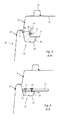
- FIG. 3 is a cross section along A-A through the support structure component according to FIG. 2 ;
- FIG. 4 is a cross section comparable to FIG. 3 , however with another motor vehicle component fastened to the support structure component;
- FIG. 5 a is a schematic representation of a first plastic fastening structure
- FIG. 5 b is a schematic representation of a second plastic fastening structure
- FIG. 5 c is a simplified, schematic representation of a further plastic fastening structure.
- the motor vehicle schematically represented in FIG. 1 is a passenger car by way of example. It comprises a body 1 and a passenger cell 2 that with respect to the vehicle longitudinal direction (x) extends between a front wheel 5 and a rear wheel 6 .
- a floor structure 3 is represented in interrupted lines, which in the region of the rear wheel 6 merges into a rear frame structure 4 .
- a support structure component 11 which as an example is a cross member is shown in perspective or sectional representation.
- This support structure component 11 can for example be configured as a rear axle cross member, which structurally interconnects the side members of the floor structure of the motor vehicle body 1 substantially extending in vehicle longitudinal direction (x) in vehicle transverse direction (y).
- the support structure component 11 comprises a support element 10 of sheet metal, into which a plastic fastening structure 30 is inserted.
- the support element 10 in this case comprises an approximately U-shaped cross-sectional profile which is almost completely filled out by the plastic fastening structure 30 .
- the support structure component 11 in this case is connected to a base portion 16 projecting upwards of a floor panel 12 extending above the support structure components 11 , preferably welded.
- a U-profile-like or top-hat profile-like reinforcement profile 14 is provided above the floor panel 12 .
- a profile portion 18 projecting downwards adjoins the base portion 16 and a connecting flange 15 of the support element 10 projecting towards the front, which in the embodiment according to FIG. 2 provides a trough 20 , for example for receiving a starter battery.
- a further motor vehicle component 22 is fastened on the support structure component 11 provided with the plastic fastening structure 30 .
- the latter in the configuration according to FIG. 2 and FIG. 3 comprises an approximately C-shaped profile, which at least in regions projects into the cross-sectional contour of the support element 10 .
- the plastic fastening structure 30 is recessed approximately L-shaped.
- the L-shaped recess 31 of the plastic fastening structure 30 makes possible an almost full area contact and bracing of the motor vehicle component 22 , which in this case can be designed for example as a fastening profile of a pull-out load carrier.
- at least one fastening element 36 is provided in the region of the plastic fastening structure 30 , which can interact with a counter-fastening element 37 of the motor vehicle component 22 for fastening the latter to the support structure component 11 .
- the plastic fastening structure 30 can be designed as a plastic molding, in particular as a plastic injection molding and comprise individual embedded fastening elements 36 enclosed by the plastic or embedded in and/or projecting there from, such as for example fastening screws or fastening nuts, clips, straps, bands or similar fastening device, with which the motor vehicle component 22 can be fastened to the support structure component 11 .
- the plastic fastening structure 30 is preferably connected to the support element 10 , in particular glued over the full area, i.e., with almost all outer contours that come into contact with the support element 10 .
- the connection of plastic fastening structure 30 and support element 10 is preferably effected with a thermally activatable adhesive 42 , as is schematically indicated in FIG. 5 a to FIG. 5 c.
- a mutual, preferably non-detachable connection of plastic fastening structure 30 and support element 10 can be effected within the course of a drying process following the painting process of the body.
- the respective plastic fastening structure 30 adapted to the provided motor vehicle component 22 has to be selected and fixed to the support element 10 at least for the duration of the production process of the body 1 , for example, with the help of fixing elements 26 forming a positive connection.
- the further embodiment according to FIG. 4 shows the connection of another motor vehicle component 24 , which is provided for example for fastening a liquefied gas tank below the floor panel 12 .
- the motor vehicle component 24 has a completely different type of geometrical configuration and requires a corresponding connection to the support structure component 11 .
- Such a configuration-specific body-side connection can be effected in particular by selecting a plastic fastening structure 32 adapted to the motor vehicle component 24 provided here. Similar to the plastic fastening structure 30 , this can be inserted into the support element 10 which compared with the embodiment according to FIG. 3 is unchanged.
- the plastic fastening structure 32 provides an entirely different type of fastening structure with different or differently positioned fastening elements 36 .
- a fastening element 37 for example designed as a screw
- the motor vehicle component 24 can be exclusively fastened to the support structure component 11 by way of the plastic fastening structure 32 .
- Adapting the body 1 with respect to its sheet metal components to different vehicle configuration-specific motor vehicle components 22 , 24 can be advantageously omitted in this respect.
- the sheet metal body-in-white structure can always be formed substantially identically and invariable despite a high degree of the diversification of vehicle configurations, so that a corresponding cost and effort savings in the body-in-white construction can be achieved.
- FIG. 5 a , FIG. 5 b and FIG. 5 c illustrates in simplified and schematic representation different connection concepts, which can be provided with the help of different plastic fastening structures 30 , 32 , 34 each of which can be inserted in one and the same support element 10 and/or connected therewith.
- the plastic fastening structure 30 according to FIG. 5 a altogether comprises four fastening elements 36 of the same type, which for example can each be formed as a screw nut embedded in the plastic fastening structure 30 .
- the embodiment according to FIG. 5 b shows a further plastic fastening structure 32 , in which comparable fastening elements 36 are provided in different positions compared with the embodiment according to FIG. 5 a .
- FIG. 5 c a variant is finally shown in which different types of fastening elements 38 , 40 are provided.
- the fastening element 38 can provide an elongated hole guide for example in the form of a guide rail embedded in the plastic fastening structure 34
- the fastening element 40 provides a standardized connection, for example for a strap tie or clamping tie for fastening a fuel tank.
- one and the same support element 10 of sheet metal can be employed here.
- a mutual connection of the support element 10 to the likewise fiber-reinforced plastic fastening structure 30 , 32 , 34 formed as an injection molding can take place by means of a thermally activatable adhesive 42 , which advantageously can already be provided in a preassembled manner on the plastic fastening structure 30 , 32 , 34 in the form of an outer coating.
Abstract
Description
Claims (18)
Applications Claiming Priority (3)
| Application Number | Priority Date | Filing Date | Title |
|---|---|---|---|
| DE102012013786.9A DE102012013786A1 (en) | 2012-07-11 | 2012-07-11 | Support structure component of a motor vehicle body with a plastic insert |
| DE102012013786 | 2012-07-11 | ||
| DE102012013786.9 | 2012-07-11 |
Publications (2)
| Publication Number | Publication Date |
|---|---|
| US20140015238A1 US20140015238A1 (en) | 2014-01-16 |
| US9051952B2 true US9051952B2 (en) | 2015-06-09 |
Family
ID=49781301
Family Applications (1)
| Application Number | Title | Priority Date | Filing Date |
|---|---|---|---|
| US13/938,710 Expired - Fee Related US9051952B2 (en) | 2012-07-11 | 2013-07-10 | Support structure component of a motor vehicle body with a plastic insert |
Country Status (3)
| Country | Link |
|---|---|
| US (1) | US9051952B2 (en) |
| CN (1) | CN103538633B (en) |
| DE (1) | DE102012013786A1 (en) |
Cited By (3)
| Publication number | Priority date | Publication date | Assignee | Title |
|---|---|---|---|---|
| USD948380S1 (en) * | 2020-03-05 | 2022-04-12 | Kia Motors Corporation | Automobile |
| USD955923S1 (en) * | 2020-03-31 | 2022-06-28 | Hyundai Motor Company | Automobile |
| USD964897S1 (en) * | 2020-07-14 | 2022-09-27 | Hyundai Motor Company | Automobile |
Families Citing this family (5)
| Publication number | Priority date | Publication date | Assignee | Title |
|---|---|---|---|---|
| JP5846193B2 (en) * | 2013-12-25 | 2016-01-20 | トヨタ自動車株式会社 | Battery mounting structure for vehicles |
| FR3041318B1 (en) * | 2015-09-18 | 2017-10-20 | Peugeot Citroen Automobiles Sa | ASSEMBLY OF METAL SHEET ELEMENTS INCLUDING FOLDING |
| US9827919B2 (en) * | 2015-10-08 | 2017-11-28 | GM Global Technology Operations LLC | Vehicle floor bracket |
| DE202018000689U1 (en) * | 2018-02-10 | 2018-12-12 | Stefan Zeuner | System for carrying, picking up and unloading loads and goods for electric motor vehicles and hybrid vehicles |
| US10696123B2 (en) | 2018-02-23 | 2020-06-30 | Ford Global Tehcnologies, LLC | Systems for a fuel tank |
Citations (15)
| Publication number | Priority date | Publication date | Assignee | Title |
|---|---|---|---|---|
| DE2930850A1 (en) | 1979-07-30 | 1981-02-05 | Braun Pebra Gmbh | Decorative or protective strip for car body - is fastened via retaining strap firmly secured to body by adhesive in strap recesses |
| US5555950A (en) * | 1992-03-04 | 1996-09-17 | Toyota Jidosha Kabushiki Kaisha | Body structure for electric vehicle |
| US6418962B1 (en) * | 1998-10-27 | 2002-07-16 | The Johns Hopkins University | Low cost, compressed gas fuel storage system |
| DE10145357C1 (en) | 2001-09-14 | 2003-05-22 | Draexlmaier Lisa Gmbh | Metal-plastics hydrid carrier for automobile body has incorporated fixing elements for cabling of automobile cable harness |
| US6615656B1 (en) * | 1994-05-09 | 2003-09-09 | Automotive Technologies International Inc. | Method and apparatus for measuring the quantity of fuel in a vehicle fuel tank subject to external forces |
| US6631775B1 (en) * | 2000-07-06 | 2003-10-14 | George T. Chaney | Electric vehicle chassis with removable battery module and a method for battery module replacement |
| DE10251762A1 (en) | 2002-11-05 | 2004-05-19 | Behr Gmbh & Co. | Girder forming part of frame structure for road vehicle body has top-hat section with channel filled with honeycomb with square cells formed by diagonal bulkheads |
| US7354102B2 (en) * | 2003-08-28 | 2008-04-08 | Magna International Inc. | Vehicle body panel with integral clip |
| US20090085329A1 (en) * | 2007-09-28 | 2009-04-02 | Dae Young Kwak | Side curtain air bag unit |
| US7581749B2 (en) * | 2007-10-12 | 2009-09-01 | Nissan Technical Center North America, Inc. | Integrated airbag panel |
| US20110143179A1 (en) * | 2009-12-10 | 2011-06-16 | Yoji Nakamori | Battery case |
| US8210301B2 (en) * | 2009-06-09 | 2012-07-03 | Fuji Jukogyo Kabushiki Kaisha | Battery mounting structure for vehicle |
| US8317227B2 (en) | 2009-12-03 | 2012-11-27 | GM Global Technology Operations LLC | Car body for a motor vehicle |
| US20130192914A1 (en) * | 2012-01-31 | 2013-08-01 | Mitsubishi Jidosha Kogyo Kabushiki Kaisha | Battery container |
| US8511413B2 (en) * | 2009-11-06 | 2013-08-20 | Kabushiki Kaisha Toyota Jidoshokki | Battery installation structure for electric automobile |
Family Cites Families (3)
| Publication number | Priority date | Publication date | Assignee | Title |
|---|---|---|---|---|
| DE10250924A1 (en) * | 2002-10-31 | 2004-05-19 | Fci | Inline clamp connector for flex ribbon cable |
| CN1882470A (en) * | 2003-11-19 | 2006-12-20 | 贝洱两合公司 | Component, particularly a lightweight hybrid component |
| DE102006021883A1 (en) * | 2006-05-11 | 2007-11-22 | GM Global Technology Operations, Inc., Detroit | Reinforcement module for a motor vehicle body |
-
2012
- 2012-07-11 DE DE102012013786.9A patent/DE102012013786A1/en not_active Withdrawn
-
2013
- 2013-07-10 CN CN201310287494.1A patent/CN103538633B/en not_active Expired - Fee Related
- 2013-07-10 US US13/938,710 patent/US9051952B2/en not_active Expired - Fee Related
Patent Citations (16)
| Publication number | Priority date | Publication date | Assignee | Title |
|---|---|---|---|---|
| DE2930850A1 (en) | 1979-07-30 | 1981-02-05 | Braun Pebra Gmbh | Decorative or protective strip for car body - is fastened via retaining strap firmly secured to body by adhesive in strap recesses |
| US5555950A (en) * | 1992-03-04 | 1996-09-17 | Toyota Jidosha Kabushiki Kaisha | Body structure for electric vehicle |
| US6615656B1 (en) * | 1994-05-09 | 2003-09-09 | Automotive Technologies International Inc. | Method and apparatus for measuring the quantity of fuel in a vehicle fuel tank subject to external forces |
| US6418962B1 (en) * | 1998-10-27 | 2002-07-16 | The Johns Hopkins University | Low cost, compressed gas fuel storage system |
| US6631775B1 (en) * | 2000-07-06 | 2003-10-14 | George T. Chaney | Electric vehicle chassis with removable battery module and a method for battery module replacement |
| US7201384B2 (en) * | 2000-07-06 | 2007-04-10 | Chaney George T | Electric vehicle chassis with removable battery module and a method for battery module replacement |
| DE10145357C1 (en) | 2001-09-14 | 2003-05-22 | Draexlmaier Lisa Gmbh | Metal-plastics hydrid carrier for automobile body has incorporated fixing elements for cabling of automobile cable harness |
| DE10251762A1 (en) | 2002-11-05 | 2004-05-19 | Behr Gmbh & Co. | Girder forming part of frame structure for road vehicle body has top-hat section with channel filled with honeycomb with square cells formed by diagonal bulkheads |
| US7354102B2 (en) * | 2003-08-28 | 2008-04-08 | Magna International Inc. | Vehicle body panel with integral clip |
| US20090085329A1 (en) * | 2007-09-28 | 2009-04-02 | Dae Young Kwak | Side curtain air bag unit |
| US7581749B2 (en) * | 2007-10-12 | 2009-09-01 | Nissan Technical Center North America, Inc. | Integrated airbag panel |
| US8210301B2 (en) * | 2009-06-09 | 2012-07-03 | Fuji Jukogyo Kabushiki Kaisha | Battery mounting structure for vehicle |
| US8511413B2 (en) * | 2009-11-06 | 2013-08-20 | Kabushiki Kaisha Toyota Jidoshokki | Battery installation structure for electric automobile |
| US8317227B2 (en) | 2009-12-03 | 2012-11-27 | GM Global Technology Operations LLC | Car body for a motor vehicle |
| US20110143179A1 (en) * | 2009-12-10 | 2011-06-16 | Yoji Nakamori | Battery case |
| US20130192914A1 (en) * | 2012-01-31 | 2013-08-01 | Mitsubishi Jidosha Kogyo Kabushiki Kaisha | Battery container |
Cited By (3)
| Publication number | Priority date | Publication date | Assignee | Title |
|---|---|---|---|---|
| USD948380S1 (en) * | 2020-03-05 | 2022-04-12 | Kia Motors Corporation | Automobile |
| USD955923S1 (en) * | 2020-03-31 | 2022-06-28 | Hyundai Motor Company | Automobile |
| USD964897S1 (en) * | 2020-07-14 | 2022-09-27 | Hyundai Motor Company | Automobile |
Also Published As
| Publication number | Publication date |
|---|---|
| DE102012013786A1 (en) | 2014-01-16 |
| CN103538633A (en) | 2014-01-29 |
| US20140015238A1 (en) | 2014-01-16 |
| CN103538633B (en) | 2017-11-17 |
Similar Documents
| Publication | Publication Date | Title |
|---|---|---|
| US9051952B2 (en) | Support structure component of a motor vehicle body with a plastic insert | |
| US9254874B2 (en) | Rear floor module of a motor vehicle | |
| US9676423B2 (en) | Rear floor module for arrangement on a motor vehicle body | |
| US8596685B2 (en) | Motor vehicle chassis having a part for attaching bodywork elements and electrical cables to the central floor | |
| US8596403B2 (en) | Motor mounting assemblies for electric vehicles and electric vehicles comprising the same | |
| US9073498B2 (en) | Battery tray for vehicle | |
| CN111051104A (en) | Method for integrating a high-voltage accumulator into a support structure of a motor vehicle, and motor vehicle | |
| CN109383258B (en) | Method for producing an electrically driven vehicle | |
| US7997377B2 (en) | Case structure of integrated package module for hybrid vehicle | |
| US7789454B2 (en) | Frame structure for vertically mounting integrated package | |
| US8807631B2 (en) | Floor module for a motor vehicle with a variable driving concept | |
| US8317227B2 (en) | Car body for a motor vehicle | |
| US20130257103A1 (en) | Floor structure of a motor vehicle body | |
| US10897034B2 (en) | Battery fastening system and method | |
| CN114174103A (en) | Energy accumulator/underbody arrangement for a motor vehicle | |
| US20220297523A1 (en) | Energy-Store Floor Assembly for a Motor Vehicle | |
| CN112753125A (en) | Motor vehicle with coupling element | |
| KR20170016457A (en) | Rear body module | |
| US7278680B2 (en) | Structural carrier assembly for a motor vehicle | |
| KR20160021454A (en) | Body center module | |
| US7628446B2 (en) | Vehicular rear cargo module | |
| US9944329B2 (en) | Structural reinforcement for vehicle body | |
| EP3594093B1 (en) | A motor vehicle floor assembly | |
| CN113016102A (en) | High-voltage memory housing for a motor vehicle | |
| US10046730B2 (en) | Support element for absorbing forces in a vehicle |
Legal Events
| Date | Code | Title | Description |
|---|---|---|---|
| AS | Assignment |
Owner name: WILMINGTON TRUST COMPANY, DELAWARE Free format text: SECURITY INTEREST;ASSIGNOR:GM GLOBAL TECHNOLOGY OPERATIONS LLC;REEL/FRAME:033135/0336 Effective date: 20101027 |
|
| AS | Assignment |
Owner name: GM GLOBAL TECHNOLOGY OPERATIONS LLC, MICHIGAN Free format text: RELEASE BY SECURED PARTY;ASSIGNOR:WILMINGTON TRUST COMPANY;REEL/FRAME:034189/0065 Effective date: 20141017 |
|
| FEPP | Fee payment procedure |
Free format text: PAYOR NUMBER ASSIGNED (ORIGINAL EVENT CODE: ASPN); ENTITY STATUS OF PATENT OWNER: LARGE ENTITY |
|
| AS | Assignment |
Owner name: GM GLOBAL TECHNOLOGY OPERATIONS LLC, MICHIGAN Free format text: ASSIGNMENT OF ASSIGNORS INTEREST;ASSIGNORS:JUETTNER, MARC;HARTMANN, JENS;SIGNING DATES FROM 20141210 TO 20150127;REEL/FRAME:034958/0231 |
|
| STCF | Information on status: patent grant |
Free format text: PATENTED CASE |
|
| MAFP | Maintenance fee payment |
Free format text: PAYMENT OF MAINTENANCE FEE, 4TH YEAR, LARGE ENTITY (ORIGINAL EVENT CODE: M1551); ENTITY STATUS OF PATENT OWNER: LARGE ENTITY Year of fee payment: 4 |
|
| FEPP | Fee payment procedure |
Free format text: MAINTENANCE FEE REMINDER MAILED (ORIGINAL EVENT CODE: REM.); ENTITY STATUS OF PATENT OWNER: LARGE ENTITY |
|
| LAPS | Lapse for failure to pay maintenance fees |
Free format text: PATENT EXPIRED FOR FAILURE TO PAY MAINTENANCE FEES (ORIGINAL EVENT CODE: EXP.); ENTITY STATUS OF PATENT OWNER: LARGE ENTITY |
|
| STCH | Information on status: patent discontinuation |
Free format text: PATENT EXPIRED DUE TO NONPAYMENT OF MAINTENANCE FEES UNDER 37 CFR 1.362 |
|
| FP | Lapsed due to failure to pay maintenance fee |
Effective date: 20230609 |