US9052305B2 - Test strip dispenser - Google Patents
Test strip dispenser Download PDFInfo
- Publication number
- US9052305B2 US9052305B2 US11/682,663 US68266307A US9052305B2 US 9052305 B2 US9052305 B2 US 9052305B2 US 68266307 A US68266307 A US 68266307A US 9052305 B2 US9052305 B2 US 9052305B2
- Authority
- US
- United States
- Prior art keywords
- test strip
- inner housing
- dispenser
- guide member
- housing
- Prior art date
- Legal status (The legal status is an assumption and is not a legal conclusion. Google has not performed a legal analysis and makes no representation as to the accuracy of the status listed.)
- Expired - Fee Related, expires
Links
Images


Classifications
-
- G—PHYSICS
- G01—MEASURING; TESTING
- G01N—INVESTIGATING OR ANALYSING MATERIALS BY DETERMINING THEIR CHEMICAL OR PHYSICAL PROPERTIES
- G01N33/00—Investigating or analysing materials by specific methods not covered by groups G01N1/00 - G01N31/00
- G01N33/48—Biological material, e.g. blood, urine; Haemocytometers
- G01N33/483—Physical analysis of biological material
- G01N33/487—Physical analysis of biological material of liquid biological material
- G01N33/4875—Details of handling test elements, e.g. dispensing or storage, not specific to a particular test method
- G01N33/48757—Test elements dispensed from a stack
-
- B—PERFORMING OPERATIONS; TRANSPORTING
- B65—CONVEYING; PACKING; STORING; HANDLING THIN OR FILAMENTARY MATERIAL
- B65D—CONTAINERS FOR STORAGE OR TRANSPORT OF ARTICLES OR MATERIALS, e.g. BAGS, BARRELS, BOTTLES, BOXES, CANS, CARTONS, CRATES, DRUMS, JARS, TANKS, HOPPERS, FORWARDING CONTAINERS; ACCESSORIES, CLOSURES, OR FITTINGS THEREFOR; PACKAGING ELEMENTS; PACKAGES
- B65D83/00—Containers or packages with special means for dispensing contents
- B65D83/08—Containers or packages with special means for dispensing contents for dispensing thin flat articles in succession
- B65D83/0805—Containers or packages with special means for dispensing contents for dispensing thin flat articles in succession through an aperture in a wall
- B65D83/0811—Containers or packages with special means for dispensing contents for dispensing thin flat articles in succession through an aperture in a wall with means for assisting dispensing
- B65D83/0823—Containers or packages with special means for dispensing contents for dispensing thin flat articles in succession through an aperture in a wall with means for assisting dispensing the articles being pushed and slid through the aperture
- B65D83/0829—Containers or packages with special means for dispensing contents for dispensing thin flat articles in succession through an aperture in a wall with means for assisting dispensing the articles being pushed and slid through the aperture by means of an actuator
-
- B—PERFORMING OPERATIONS; TRANSPORTING
- B65—CONVEYING; PACKING; STORING; HANDLING THIN OR FILAMENTARY MATERIAL
- B65D—CONTAINERS FOR STORAGE OR TRANSPORT OF ARTICLES OR MATERIALS, e.g. BAGS, BARRELS, BOTTLES, BOXES, CANS, CARTONS, CRATES, DRUMS, JARS, TANKS, HOPPERS, FORWARDING CONTAINERS; ACCESSORIES, CLOSURES, OR FITTINGS THEREFOR; PACKAGING ELEMENTS; PACKAGES
- B65D2583/00—Containers or packages with special means for dispensing contents
- B65D2583/08—Containers or packages with special means for dispensing contents for dispensing thin flat articles in succession
- B65D2583/082—Details relating to containers for dispensing thin flat articles in succession
Definitions
- test strips are stored in a disposable container that is separate from the apparatus that measures the fluid component of interest.
- a test strip is removed from the container, a fluid sample is dispensed onto the strip, and the strip is inserted into a photometric or electrochemical meter for analysis of the desired component. After analysis is completed, the test strip is extracted from the meter and the strip is discarded.
- Ease of use of hand held test strip dispensers and meters is important, particularly for those dispensers that will be used by persons with diminished hand-eye coordination or finger sensation.
- persons with diabetes typically have either or both impaired vision and diminished fingertip sensation.
- Such persons must use test strips and meters to test their blood glucose levels a number of times a day.
- the typical test strip is only several millimeters in width and length and, thus, difficult to manipulate.
- conventional strips are typically packed in small, cylindrical containers from which it is difficult to easily extract a single strip
- a test strip dispenser that dispenses one test strip at a time.
- the test strip dispenser includes an interior volume to store a plurality of test strips, an aperture through which a test strip is dispensed and a groove.
- the test strip dispenser further includes a biasing device that disposes the inner housing in a first direction and an outer housing.
- the outer housing includes an opening in substantial alignment with the aperture of the inner housing to allow for passage of the test strip.
- the outer housing further includes a guide member that mates with the groove of the inner housing so that the test strip remains stationary when the inner housing is moved along the guide member of the outer housing in a direction generally opposite the first direction.
- a system that delivers a test strip to a testing position.
- the system includes a plurality of test strips stored inside a test strip dispenser and a meter.
- the test strip dispenser includes an interior volume to store a plurality of test strips, an aperture through which a test strip is dispensed and a groove.
- the test strip dispenser further includes a biasing device that disposes the inner housing in a first direction and an outer housing.
- the outer housing includes an opening in substantial alignment with the aperture of the inner housing to allow for passage of the test strip.
- the outer housing further includes a guide member that mates with the groove of the inner housing so that the test strip remains stationary when the inner housing is moved along the guide member of the outer housing in a direction generally opposite the first direction.
- the meter includes a strip port configured to engage the inner housing of the test strip dispenser so that the inner housing moves along the guide member while a strip port connector within the meter engages the test strip.
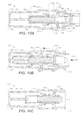
- FIGS. 1A , 1 B and 1 C are perspective, exploded and partially exploded views, respectively, of a test strip dispenser according to an exemplary embodiment
- FIGS. 2 , 3 and 4 are cross-sectional views of the test strip dispenser illustrated in FIG. 1A .
- FIG. 5 is a perspective partial cross-sectional view of the outer housing of the test strip dispenser shown in FIGS. 1A-1C ;
- FIGS. 6 and 7 are perspective partial cross-sectional views of the outer housing of a test strip dispenser according to other exemplary embodiments.
- FIG. 8A is a perspective close up view of the first end of the inner housing of the test strip dispenser shown in FIGS. 1A-1C ;
- FIG. 8B is a perspective close up view of the proximal end of the inner housing of the test strip dispenser shown in FIGS. 1A-1C ;
- FIGS. 9A-9D are schematic partial cross-sectional side views of a sequence of steps used in a process for dispensing a test strip from a test strip dispenser to a test position in a meter;
- FIGS. 10A-10C are schematic cross-sectional top views of a sequence of steps used in an anti-jamming process
- FIGS. 11A-11C are perspective, exploded and partially exploded views, respectively, of a test strip dispenser
- FIGS. 12 and 13 are cross-sectional views of the test strip dispenser shown in FIGS. 11A-11C ;
- FIG. 14 is a perspective, partial cross-sectional view of the outer housing of the test strip dispenser shown in FIGS. 11A-11C ;
- FIG. 15 is a perspective view of the first end of the inner housing of the test strip dispenser shown in FIGS. 11A-11C ;
- FIG. 16 is a close up perspective view of the inner surface of the second portion of the inner housing shown in FIG. 11B ;
- FIGS. 17A-17D are schematic partial cross-sectional side views of a sequence of steps used in a process for dispensing a test strip from a test strip dispenser to a test position;
- FIG. 18 is a close up perspective view of the inner surface of the second portion of the inner housing shown in FIG. 11B illustrating the location of a test strip being dispensed during a test strip dispensing process.
- test strip dispensing methods and devices suited for storage or delivery of a wide variety of electrochemical test strips and photometric test strips, such as test strips suitable for use in the determination of analytes in whole blood or derivatives thereof.
- the test strip can store a plurality of such test strips and can dispense individual test strips for receipt by a diagnostic device known as in the art as a “meter.”
- test strip dispensing systems that include a meter configured to mate with the test strip dispenser and to receive test strips therefrom.
- FIGS. 1A-1C and FIGS. 2-4 illustrate a test strip dispenser 100 according to an exemplary embodiment.
- Test strip dispenser 100 includes a proximal end 102 , a distal end 104 , an outer housing 106 and an inner housing 108 .
- Inner housing 108 which is configured to house a plurality of test strips 200 (e.g., a stack of test strips), is nested inside outer housing 106 and is moveable therein.
- Outer housing 106 and inner housing 108 are generally rectangular in shape and may be formed of a suitable material, preferably such as, for example, acrylonitrile butadiene styrene, polycarbonate or combinations thereof.
- test strip 200 that can be used with various embodiments described and illustrated herein are generally elongate in shape and are sized to fit within inner housing.
- test strip 200 can be, for example, a OneTouch® Ultra® brand glucose test strip or other suitable test strips that are commercially available.
- Each of the plurality of test strips 200 is usually stored in test strip dispenser 100 with the distal end on which a fluid sample is applied extending toward distal end of test strip dispenser 100 and, for electrochemical type test strips, with the proximal end containing electrical connections extending toward proximal end of the test strip dispenser 100 . This ensures that when a single test strip is removed from test strip dispenser 100 by a meter, the test strip will be in a correct orientation for applying the fluid sample and, for electrochemical type test strips, for making an electrical connection with the meter.
- outer housing 106 includes a first member 110 and a second member 112 .
- Second member 112 includes an opening 114 for gaining access to test strip 200 stored in an inner housing 108 .
- First member 110 and second member 112 are joined together by, for example, a snap fit or ultrasonic welding to form a space for holding inner housing therein.
- outer housing 106 further includes a guide member 116 on a first inner surface 118 , a first recess 120 on a second inner surface 122 and an optional second recess 124 on a third inner surface 126 .
- Guide member 116 includes a ledge 128 and a stop 130 on a proximal end 136 and a surface 132 on which inner housing 108 moves.
- Guide member 116 optionally includes a first spring locator 134 on proximal end 136 .
- the cross section of guide member 116 is t-shaped.
- guide member 116 may be a modified to shape in which a left or right arm, respectively, is removed.
- inner housing 108 includes a proximal end 138 , a distal end 140 , a first side 142 , a second side 144 , a first end 146 and a second end 148 .
- Proximal end 138 of inner housing 108 includes a projection 150 with an aperture 152 through which a test strip travels during dispensing.
- Projection 150 is oblong in shape and is configured to fit within opening 114 in outer housing 106 .
- Inner housing 108 is biased toward proximal end 102 of test strip dispenser 100 by a spring 154 .
- Spring 154 may be located proximal to guide member 116 , as shown in FIG. 2 , or may be located distal to proximal end 138 of inner housing 108 as illustrated in FIG. 12 . Having spring 154 located proximal to guide member 116 results in a more compact test strip dispenser 100 .
- a second spring locator 156 is optionally located on a first side 160 of a protrusion 162 on first end 146 of inner housing 108 (see FIGS. 2 and 8A ).
- inner housing 108 further includes a groove 158 at first end 146 that mates with and moves on guide member 116 on first inner surface 118 of outer housing 106 during test strip dispensing, as will be described in more detail with reference to FIGS. 9A-9D .
- groove 158 is t-shaped and spans about one fourth of the distance from distal end 140 to proximal end 138 of inner housing 108 .
- groove 158 is illustrated as having a “T” cross-section, groove 158 may be of any shape compatible with the shape of guide member 116 as long as the groove 158 mates and moves on guide member 116 .
- a spring-loaded platform 164 biases plurality of strips 200 toward first end 146 of inner housing 108 .
- An example spring used to bias platform 164 is a spiral spring 166 .
- a first end 168 of spiral spring 166 may be held in place in a slot 170 near first end 146 of inner housing 108 (see FIG. 1B ).
- first end 168 of spiral spring 166 may be coupled near first end 146 of inner housing 108 by a suitable process such as, for example, plastic welding, bonding, or preferably heat staking.
- a second end 172 of spiral spring 166 forms a spiral that resides in a niche 174 in platform 164 .
- spiral spring 166 may optionally extend through a longitudinal space 176 in first side 146 of inner housing 108 .
- Inner housing 108 further includes an anti-jamming mechanism having at least one flipper 180 with a first end 182 and a second end 184 , as illustrated in FIG. 4 .
- First end 182 of at least one flipper 180 is pivotally attached to first side 142 of inner housing 108 with, for example, a hinge 186 .
- Second end 184 of at least one flipper 180 includes an arm 188 that engages a sloping surface 190 of first recess 120 of outer housing 106 if a test strip is not engaged by a meter during test strip dispensing, as will be described with reference to FIG. 10C .
- FIGS. 9A-9D and 10 A- 10 C together, a sequence of steps in a method for dispensing a test strip is illustrated.
- the provision of an exemplary test strip dispenser that may be used with the subject method is depicted in FIGS. 1A-1C , 2 - 4 and 8 A- 8 B in which like elements of the test strip dispenser of the earlier figures are identified with like numerals.
- test strip dispenser 100 housing plurality of test strips 200 and a meter 220 are provided according to exemplary embodiments (see FIGS. 9A and 10A ). Prior to a first test strip 202 being dispensed, test strip dispenser 100 is in a rest position in which groove 158 of inner housing 108 rests on surface 132 of guide member 116 and plurality of test strips 200 rests on ledge 128 of guide member 116 .
- a strip port 222 of meter 220 is then inserted into opening 114 of outer housing 106 and strip port 222 engages with projection 150 of inner housing 108 , urging inner housing 108 toward distal end 104 of test strip dispenser 100 along guide member 116 . While inner housing 108 is urged along guide member 116 , first test strip 202 remains substantially stationary while the remaining plurality of test strips 200 moves toward distal end 104 of test strip dispenser 100 .
- first test strip 202 engages incline of second end 184 of at least one flipper 180 , pushing at least one flipper 180 laterally outward and toward the inner walls of outer housing 106 .
- Inner housing 108 continues to be urged along guide member 116 until it is pushed toward distal end 104 of test strip dispenser 100 as far as possible, at which time the distal end of first test strip 202 is engaged with stop 130 of guide member 116 and the proximal end of first test strip 202 is engaged with a strip port connector 224 of meter 220 , as illustrated in FIGS. 9B and 10B .
- stop 130 is usually slightly smaller than the thickness of the test strip so that only one test strip at a time is engaged with stop 130 .
- arm 188 on second end 184 of the at least one flipper 180 moves freely within first recess 120 of outer housing 106 .
- first test strip 202 is pulled through aperture 152 in projection 150 of inner housing 108 , and inner housing 108 is biased toward proximal end 102 of test strip dispenser 100 (see FIG. 9C ).
- aperture 152 is sized to accommodate only one test strip at a time.
- a second test strip is biased by platform toward first end 146 of inner housing 108 into a dispensing position (not shown).
- arm 188 of at least one flipper 180 engages with sloping surface 190 in first recess 120 of outer housing 106 , preventing inner housing 108 from moving back to the rest position and preventing the distal end of a second test strip from engaging with stop 130 of guide member 116 (see FIG. 10C ).
- Inner housing 108 remains locked in this anti-jamming position until the meter is urged against inner housing 108 again and strip port connector 224 engages first test strip 202 .
- first test strip 202 is completely removed from test strip dispenser 100 while remaining engaged in strip port connector 224 of meter 220 and is positioned for testing.
- FIGS. 11A-11C and FIGS. 12-16 illustrate a test strip dispenser 300 according to another exemplary embodiment.
- Test strip dispenser 300 includes a proximal end 302 , a distal end 304 , an outer housing 306 and an inner housing 308 .
- Inner housing 308 which is configured to house a plurality of test strips 400 (e.g., a stack of test strips), is nested inside outer housing 306 and is moveable therein.
- Outer housing 306 and inner housing 308 are generally rectangular in shape and may be formed of a suitable material, preferably such as acrylonitrile butadiene styrene, polycarbonate or combinations thereof.
- test strip 400 can be, for example, a glucose test strip as shown and described in U.S. Pat. No. 6,749,887, which is hereby incorporated in full by reference.
- test strip 400 can be, for example, a glucose test strip as shown and described in U.S. Pat. No. 6,749,887, which is hereby incorporated in full by reference.
- the other suitable commercially available test strips may also be used with various embodiments described and illustrated herein.
- Each of the plurality of test strips 400 is usually stored in test strip dispenser 300 with the distal end on which a fluid sample is applied extending toward distal end 304 of test strip dispenser 300 and, for electrochemical type test strips, with the proximal end containing electrical connections extending toward proximal end 302 of test strip dispenser 300 .
- This ensures that when a single test strip is removed from test strip dispenser 300 by a meter, the test strip will be in a correct orientation for applying the fluid sample and, for electrochemical type test strips, for making an electrical connection with the meter.
- outer housing 306 includes a first member 310 and a second member 312 with an opening 314 for gaining access to a test strip stored in inner housing 308 .
- First member 310 and second member 312 are joined together by, for example, ultrasonic welding or a snap fit to form a space for holding inner housing 308 therein.
- outer housing 306 further includes a guide member 316 on a first inner surface 318 and an optional spring locator 334 on a second inner surface 320 .
- guide member 316 is t-shaped and includes a ledge 322 , a stop 324 on a proximal end 336 and a surface 326 on which inner housing 308 moves.
- guide member 316 may be a modified t shape in which a left or right arm, respectively, is removed (not shown).
- inner housing 308 includes a first portion 330 and a second portion 332 joined together by, for example, screws or ultrasonic welding to form a cavity configured to house plurality of test strips 400 .
- Inner housing 308 may also be formed of a single molded body. As shown in FIG. 11C , in assembled form, inner housing includes a proximal end 338 , a distal end 340 , a first side 342 , a second side 344 , a first end 346 and a second end 348 .
- Proximal end 338 of inner housing 308 includes a projection 350 with an aperture 352 through which a test strip travels during dispensing.
- Projection 350 is oblong in shape and is configured to fit within opening 314 in outer housing 306 .
- Inner housing 308 is biased toward proximal end 302 of test strip dispenser 300 by a spring 354 .
- Spring 354 is located distal to proximal end 338 of inner housing 308 as illustrated in FIG. 12 .
- Inner housing 308 may optionally include a recess 356 on distal end 340 for locating an end of spring 354 (see FIGS. 12 and 15 ).
- inner housing 308 further includes a groove 358 at first end 346 that mates with and moves on guide member 316 on first inner surface 318 of outer housing 306 during test strip dispensing, as will be described in more detail with reference to FIGS. 17A-17D .
- groove 358 may be t-shaped and spans the length of first end 346 of inner housing 308 .
- the groove 358 may be any shape compatible with the shape of guide member 316 .
- inner housing 308 further includes a first shelf 360 on which plurality of test strips 400 rests before and during test strip dispensing and a second shelf 362 on a first inner surface 364 in which a test strip being dispensed drops during test strip dispensing. Additionally, inner housing 308 includes an arm 366 projecting from a second inner surface 368 near proximal end 338 of inner housing 308 that engages the plurality of test strips 400 not being dispensed during the dispensing process, as will be described below. Arm 366 also forms one side of a channel 367 through which only one test strip at a time can move. The other side of channel 367 is formed by second shelf 362 .
- a spring-loaded platform 370 biases plurality of strips 400 toward first end 346 of inner housing 308 .
- An example spring used to bias platform is a spiral spring 372 .
- a first end 374 of spiral spring 372 may be held in place in a slot 376 near first end 346 of inner housing 308 .
- first end 374 of spiral spring 372 may be affixed near first end 346 of inner housing 108 by a process such as heat staking.
- a second end 378 of spiral spring 372 forms a spiral that resides in a niche 380 in platform 370 .
- spiral spring 372 may optionally extend through a longitudinal space (not shown) in first side 346 of inner housing 308 .
- Inner housing 308 may optionally include a window 382 in first side 342 or second side 344 for viewing the number of test strips remaining in inner housing 308 (see FIG. 11B ).
- both the inner and outer housings may be formed of a generally transparent material or even a translucent material to allow for visualization of the number of test strips remaining in the dispenser.
- FIGS. 17A-17D and FIG. 18 together, a sequence of steps in a method for dispensing a test strip.
- the provision of an exemplary test strip dispenser that may be used with the subject method is depicted in FIGS. 11A-11C and 12 - 16 in which like elements of the test strip dispenser of the earlier figures are identified with like numerals.
- test strip dispenser 300 housing plurality of test strips 400 and a meter 420 are provided according to exemplary embodiments (see FIG. 17A ).
- test strip dispenser 300 Prior to a first test strip 402 being dispensed, test strip dispenser 300 is in a rest position in which a portion of groove 358 of inner housing 308 rests on surface 326 of guide member 316 and plurality of test strips 400 rests on first shelf 360 in first inner surface 364 of inner housing 308 (see FIG. 18 for first shelf 360 ).
- a strip port 422 of meter 420 is then inserted into opening 314 of outer housing 306 and strip port 422 engages with projection 350 of inner housing 308 , urging inner housing 308 toward distal end 304 of test strip dispenser 300 along guide member 316 . While inner housing 308 is urged along guide member 316 , arm 366 projecting from second inner surface 368 of inner housing 308 engages all of the plurality of test strips 400 except first test strip 402 . At this step, first test strip 402 remains substantially stationary while the remaining plurality of test strips 400 moves toward distal end 304 of test strip dispenser 300 .
- Inner housing 308 continues to be urged along guide member 316 until it is pushed toward distal end 304 of test strip dispenser 300 as far as possible, at which time first test strip 402 drops onto second shelf 362 on first inner surface 364 of inner housing 308 and the distal end of first test strip 402 is engaged with stop 324 of guide member 316 (see FIGS. 17B and 18 ). At or near the same time the distal end of first test strip 402 is engaged with stop 324 of guide member 316 , the proximal end of first test strip 402 is engaged with a strip port connector 424 of meter 420 . First test strip 402 drops onto second shelf 362 to release pressure on the remaining plurality of test strips 400 moving toward distal end 304 of test strip dispenser 300 and to lessen the retention force required by strip port connector 424 .
- first test strip 402 is pulled through channel 367 and then is pulled through aperture 352 in projection 350 of inner housing 308 .
- inner housing 308 is biased toward proximal end 302 of test strip dispenser 300 .
- first test strip 402 is completely removed from test strip dispenser 300 while remaining engaged in strip port connector 424 of meter 420 and is positioned for testing.
Abstract
Description
Claims (16)
Priority Applications (8)
| Application Number | Priority Date | Filing Date | Title |
|---|---|---|---|
| US11/682,663 US9052305B2 (en) | 2007-03-06 | 2007-03-06 | Test strip dispenser |
| EP08250743.5A EP1967852B1 (en) | 2007-03-06 | 2008-03-05 | Test Strip dispenser |
| CA002624055A CA2624055A1 (en) | 2007-03-06 | 2008-03-05 | Test strip dispenser |
| ES08250743.5T ES2555378T3 (en) | 2007-03-06 | 2008-03-05 | Test strip dispenser |
| JP2008056867A JP5579968B2 (en) | 2007-03-06 | 2008-03-06 | Specimen dispenser |
| CN200810082488.1A CN101266241B (en) | 2007-03-06 | 2008-03-06 | Test strip dispenser |
| HK08113088.8A HK1124116A1 (en) | 2007-03-06 | 2008-12-01 | Test strip dispenser |
| US14/704,042 US20150233891A1 (en) | 2007-03-06 | 2015-05-05 | Test strip dispenser |
Applications Claiming Priority (1)
| Application Number | Priority Date | Filing Date | Title |
|---|---|---|---|
| US11/682,663 US9052305B2 (en) | 2007-03-06 | 2007-03-06 | Test strip dispenser |
Related Child Applications (1)
| Application Number | Title | Priority Date | Filing Date |
|---|---|---|---|
| US14/704,042 Division US20150233891A1 (en) | 2007-03-06 | 2015-05-05 | Test strip dispenser |
Publications (2)
| Publication Number | Publication Date |
|---|---|
| US20080217354A1 US20080217354A1 (en) | 2008-09-11 |
| US9052305B2 true US9052305B2 (en) | 2015-06-09 |
Family
ID=39473896
Family Applications (2)
| Application Number | Title | Priority Date | Filing Date |
|---|---|---|---|
| US11/682,663 Expired - Fee Related US9052305B2 (en) | 2007-03-06 | 2007-03-06 | Test strip dispenser |
| US14/704,042 Abandoned US20150233891A1 (en) | 2007-03-06 | 2015-05-05 | Test strip dispenser |
Family Applications After (1)
| Application Number | Title | Priority Date | Filing Date |
|---|---|---|---|
| US14/704,042 Abandoned US20150233891A1 (en) | 2007-03-06 | 2015-05-05 | Test strip dispenser |
Country Status (7)
| Country | Link |
|---|---|
| US (2) | US9052305B2 (en) |
| EP (1) | EP1967852B1 (en) |
| JP (1) | JP5579968B2 (en) |
| CN (1) | CN101266241B (en) |
| CA (1) | CA2624055A1 (en) |
| ES (1) | ES2555378T3 (en) |
| HK (1) | HK1124116A1 (en) |
Cited By (3)
| Publication number | Priority date | Publication date | Assignee | Title |
|---|---|---|---|---|
| US10663451B2 (en) | 2014-06-05 | 2020-05-26 | Roche Diabetes Care, Inc. | Interchangeable test element retainers |
| US10945568B1 (en) * | 2019-09-17 | 2021-03-16 | Lianne Chase | Rubbing alcohol dispenser apparatus |
| US11517896B2 (en) | 2020-08-14 | 2022-12-06 | Luna Pharmaceuticals, Inc. | Test strip holder |
Families Citing this family (20)
| Publication number | Priority date | Publication date | Assignee | Title |
|---|---|---|---|---|
| GB2441594B (en) * | 2006-09-08 | 2011-09-07 | Thermo Shandon Ltd | Hopper for storing coverslips |
| US7935307B2 (en) * | 2007-05-31 | 2011-05-03 | EOS Health, DVC. | Disposable, refillable glucometer with cell phone interface for transmission of results |
| TWM368068U (en) * | 2009-06-19 | 2009-11-01 | Apex Biotechnology Corp | Holding device for medical test strip |
| ITPI20100011A1 (en) * | 2010-02-04 | 2011-08-05 | David Ciofalo | AUTOMATIC DISTRIBUTOR OF SACRED OSTIES. |
| US8550295B2 (en) * | 2010-02-22 | 2013-10-08 | Roche Diagnostics Operations, Inc. | Container for dispensing a single test strip |
| US8535618B1 (en) | 2010-09-08 | 2013-09-17 | Robert L. Werner | Test strip dispenser |
| CN102048240B (en) * | 2010-12-23 | 2012-07-11 | 东莞市天信金属制品有限公司 | Disposable automatic environmentally-friendly packaging box |
| CA2832425A1 (en) * | 2011-04-08 | 2012-10-11 | Csp Technologies, Inc. | Strip dispenser and strips for use with the same |
| US9924892B2 (en) * | 2011-05-31 | 2018-03-27 | Tara Chand Singhal | Integrated blood glucose measuring device |
| WO2013059483A1 (en) | 2011-10-20 | 2013-04-25 | Jabil Circuit, Inc. | Cartridge and metering device for fluid- testing strips |
| CA2873410C (en) * | 2012-05-31 | 2017-10-03 | Bayer Healthcare Llc | Multistrip cartridge |
| CN103991638B (en) * | 2013-02-18 | 2016-08-31 | 上海优爱宝机器人技术有限公司 | Test strip Storage Box and take the device of test strip in it |
| CN103496515A (en) * | 2013-10-25 | 2014-01-08 | 南京鱼跃软件技术有限公司 | Testing strip packing box |
| WO2015066673A1 (en) * | 2013-11-04 | 2015-05-07 | Csp Technologies, Inc. | Container with singulating mechanism |
| CN105800126B (en) * | 2016-05-10 | 2018-08-21 | 北京峰誉科技有限公司 | A kind of paper box applied to intelligent closestool and the intelligent closestool containing the paper box |
| CA2977509C (en) | 2016-08-30 | 2021-08-03 | Wal-Mart Stores, Inc. | Dry eraser and associated systems and methods |
| CA2977506A1 (en) * | 2016-08-30 | 2018-02-28 | Wal-Mart Stores, Inc. | Dry eraser and associated systems and methods |
| DE102016116668A1 (en) * | 2016-09-06 | 2018-03-08 | Sanner Gmbh | Dispensers for objects, in particular for test strips |
| WO2020096829A1 (en) * | 2018-11-08 | 2020-05-14 | Samuel, Son & Co. (Usa) Inc. | Component feeding system |
| CN113173332B (en) * | 2021-04-20 | 2022-07-26 | 华中科技大学同济医学院附属协和医院 | Anti-pollution formula blood sugar test paper box |
Citations (26)
| Publication number | Priority date | Publication date | Assignee | Title |
|---|---|---|---|---|
| US788730A (en) * | 1903-07-20 | 1905-05-02 | Edward Rogers | Match-box. |
| US914040A (en) * | 1908-03-14 | 1909-03-02 | George T Haines | Ticket-case. |
| US1756439A (en) * | 1926-02-03 | 1930-04-29 | Magazine Repeating Razor Co | Safety razor |
| US2288870A (en) * | 1942-07-07 | Method of and apparatus for deliv | ||
| US3563412A (en) * | 1967-11-08 | 1971-02-16 | Wilkinson Sword Ltd | Razor blade dispensers |
| US4872593A (en) * | 1988-01-11 | 1989-10-10 | Behringer John W | Dispenser for packaged bandages and the like |
| US5337897A (en) * | 1990-05-21 | 1994-08-16 | Gerald Yablans | Sampler cartridge display case and unit sampler |
| US5383569A (en) * | 1992-05-15 | 1995-01-24 | Muto Pure Chemicals Company Ltd. | Automatic delivery apparatus for prepared slide glass sheets |
| US5505308A (en) | 1993-08-27 | 1996-04-09 | Boehringer Mannheim Gmbh | System for the storage of test elements |
| US6176119B1 (en) | 1997-12-13 | 2001-01-23 | Roche Diagnostics Gmbh | Analytical system for sample liquids |
| JP2002116214A (en) | 2000-10-10 | 2002-04-19 | Hitachi Ltd | Specimen conveyance apparatus |
| US20020162849A1 (en) * | 2001-05-04 | 2002-11-07 | Chen Fang Yeh | Structure art design knife blade container |
| US20030002387A1 (en) | 1997-04-11 | 2003-01-02 | Gunter Bottwein | Magazine for storing test elements |
| EP1321769A1 (en) | 2001-12-21 | 2003-06-25 | Lifescan, Inc. | Test device with means for storing and dispensing diagnostic strips |
| US20030212345A1 (en) | 2002-05-09 | 2003-11-13 | Mcallister Devin | Minimal procedure analyte test system |
| US20040178216A1 (en) | 2003-01-14 | 2004-09-16 | David Brickwood | Sensor dispensing device |
| US20050186162A1 (en) | 2002-04-05 | 2005-08-25 | Arkray, Inc. | Analytical appliance cartridge with retrieval mechanism, and set of the cartridge and analyzer |
| US20050281706A1 (en) * | 2004-06-18 | 2005-12-22 | Tom Funke | Dispenser for flattened articles |
| US6997343B2 (en) | 2001-11-14 | 2006-02-14 | Hypoguard Limited | Sensor dispensing device |
| WO2006047135A1 (en) | 2004-10-21 | 2006-05-04 | Bayer Healthcare Llc | Sensor-dispensing device and mechanism for extracting sensor |
| US20060118570A1 (en) | 2004-12-03 | 2006-06-08 | Nova Biomedical Corporation | Test Strip Dispenser |
| US20060182656A1 (en) | 2004-06-18 | 2006-08-17 | Tom Funke | Dispenser for flattened articles |
| US7138089B2 (en) * | 2000-07-20 | 2006-11-21 | Hypoguard Limited | Test device for analyzing blood glucose or other analytes in bodily fluids |
| EP1726950A1 (en) | 2005-05-24 | 2006-11-29 | F. Hoffmann-La Roche Ag | Cartridge for storing test elements |
| US20060266765A1 (en) | 2005-05-25 | 2006-11-30 | Lifescan, Inc. | Sensor dispenser device and method of use |
| US20080094804A1 (en) * | 2005-01-14 | 2008-04-24 | Reynolds Jeffrey S | Test Sensor Cartridges and Sensor-Dispensing Instruments |
Family Cites Families (8)
| Publication number | Priority date | Publication date | Assignee | Title |
|---|---|---|---|---|
| US4296070A (en) * | 1980-06-16 | 1981-10-20 | Eastman Kodak Company | Slide distributor for a chemical analyzer |
| JPH06213904A (en) * | 1993-01-18 | 1994-08-05 | Hitachi Ltd | Test piece supplying apparatus |
| US5692747A (en) * | 1995-04-27 | 1997-12-02 | Hewlett-Packard Company | Combination flipper sorter stacker and mail box for printing devices |
| US20050182656A1 (en) * | 1999-05-28 | 2005-08-18 | Morey Fred R. | On-line prescription service system and method |
| GB0017737D0 (en) * | 2000-07-20 | 2000-09-06 | Hypoguard Limited | Test device |
| US6749887B1 (en) * | 2001-11-28 | 2004-06-15 | Lifescan, Inc. | Solution drying system |
| JP3711097B2 (en) * | 2002-08-12 | 2005-10-26 | 株式会社ヨコタコーポレーション | Specimen supply device and urine inspection device using the same |
| GB0300765D0 (en) * | 2003-01-14 | 2003-02-12 | Hypoguard Ltd | Sensor dispensing device |
-
2007
- 2007-03-06 US US11/682,663 patent/US9052305B2/en not_active Expired - Fee Related
-
2008
- 2008-03-05 ES ES08250743.5T patent/ES2555378T3/en active Active
- 2008-03-05 CA CA002624055A patent/CA2624055A1/en not_active Abandoned
- 2008-03-05 EP EP08250743.5A patent/EP1967852B1/en not_active Not-in-force
- 2008-03-06 CN CN200810082488.1A patent/CN101266241B/en not_active Expired - Fee Related
- 2008-03-06 JP JP2008056867A patent/JP5579968B2/en not_active Expired - Fee Related
- 2008-12-01 HK HK08113088.8A patent/HK1124116A1/en not_active IP Right Cessation
-
2015
- 2015-05-05 US US14/704,042 patent/US20150233891A1/en not_active Abandoned
Patent Citations (30)
| Publication number | Priority date | Publication date | Assignee | Title |
|---|---|---|---|---|
| US2288870A (en) * | 1942-07-07 | Method of and apparatus for deliv | ||
| US788730A (en) * | 1903-07-20 | 1905-05-02 | Edward Rogers | Match-box. |
| US914040A (en) * | 1908-03-14 | 1909-03-02 | George T Haines | Ticket-case. |
| US1756439A (en) * | 1926-02-03 | 1930-04-29 | Magazine Repeating Razor Co | Safety razor |
| US3563412A (en) * | 1967-11-08 | 1971-02-16 | Wilkinson Sword Ltd | Razor blade dispensers |
| US4872593A (en) * | 1988-01-11 | 1989-10-10 | Behringer John W | Dispenser for packaged bandages and the like |
| US5337897A (en) * | 1990-05-21 | 1994-08-16 | Gerald Yablans | Sampler cartridge display case and unit sampler |
| US5383569A (en) * | 1992-05-15 | 1995-01-24 | Muto Pure Chemicals Company Ltd. | Automatic delivery apparatus for prepared slide glass sheets |
| US5505308A (en) | 1993-08-27 | 1996-04-09 | Boehringer Mannheim Gmbh | System for the storage of test elements |
| US20030002387A1 (en) | 1997-04-11 | 2003-01-02 | Gunter Bottwein | Magazine for storing test elements |
| US6176119B1 (en) | 1997-12-13 | 2001-01-23 | Roche Diagnostics Gmbh | Analytical system for sample liquids |
| US6378702B1 (en) | 1997-12-13 | 2002-04-30 | Roche Diagnostics Gmbh | Test element storage container |
| US7138089B2 (en) * | 2000-07-20 | 2006-11-21 | Hypoguard Limited | Test device for analyzing blood glucose or other analytes in bodily fluids |
| JP2002116214A (en) | 2000-10-10 | 2002-04-19 | Hitachi Ltd | Specimen conveyance apparatus |
| US20020162849A1 (en) * | 2001-05-04 | 2002-11-07 | Chen Fang Yeh | Structure art design knife blade container |
| US6997343B2 (en) | 2001-11-14 | 2006-02-14 | Hypoguard Limited | Sensor dispensing device |
| EP1321769A1 (en) | 2001-12-21 | 2003-06-25 | Lifescan, Inc. | Test device with means for storing and dispensing diagnostic strips |
| US6908008B2 (en) * | 2001-12-21 | 2005-06-21 | Lifescan, Inc. | Test device with means for storing and dispensing diagnostic strips |
| US20050186162A1 (en) | 2002-04-05 | 2005-08-25 | Arkray, Inc. | Analytical appliance cartridge with retrieval mechanism, and set of the cartridge and analyzer |
| US20030212345A1 (en) | 2002-05-09 | 2003-11-13 | Mcallister Devin | Minimal procedure analyte test system |
| EP1362551A1 (en) | 2002-05-09 | 2003-11-19 | Lifescan, Inc. | Minimal procedure analyte test system |
| JP2004113771A (en) | 2002-05-09 | 2004-04-15 | Lifescan Inc | Sample detecting system and method for analyzing concentration of sample |
| US20040178216A1 (en) | 2003-01-14 | 2004-09-16 | David Brickwood | Sensor dispensing device |
| US20050281706A1 (en) * | 2004-06-18 | 2005-12-22 | Tom Funke | Dispenser for flattened articles |
| US20060182656A1 (en) | 2004-06-18 | 2006-08-17 | Tom Funke | Dispenser for flattened articles |
| WO2006047135A1 (en) | 2004-10-21 | 2006-05-04 | Bayer Healthcare Llc | Sensor-dispensing device and mechanism for extracting sensor |
| US20060118570A1 (en) | 2004-12-03 | 2006-06-08 | Nova Biomedical Corporation | Test Strip Dispenser |
| US20080094804A1 (en) * | 2005-01-14 | 2008-04-24 | Reynolds Jeffrey S | Test Sensor Cartridges and Sensor-Dispensing Instruments |
| EP1726950A1 (en) | 2005-05-24 | 2006-11-29 | F. Hoffmann-La Roche Ag | Cartridge for storing test elements |
| US20060266765A1 (en) | 2005-05-25 | 2006-11-30 | Lifescan, Inc. | Sensor dispenser device and method of use |
Cited By (4)
| Publication number | Priority date | Publication date | Assignee | Title |
|---|---|---|---|---|
| US10663451B2 (en) | 2014-06-05 | 2020-05-26 | Roche Diabetes Care, Inc. | Interchangeable test element retainers |
| US11237151B2 (en) * | 2014-06-05 | 2022-02-01 | Roche Diagnostics Operations, Inc. | Interchangeable test element retainers |
| US10945568B1 (en) * | 2019-09-17 | 2021-03-16 | Lianne Chase | Rubbing alcohol dispenser apparatus |
| US11517896B2 (en) | 2020-08-14 | 2022-12-06 | Luna Pharmaceuticals, Inc. | Test strip holder |
Also Published As
| Publication number | Publication date |
|---|---|
| JP2008216258A (en) | 2008-09-18 |
| US20150233891A1 (en) | 2015-08-20 |
| CN101266241A (en) | 2008-09-17 |
| HK1124116A1 (en) | 2009-07-03 |
| CN101266241B (en) | 2016-09-07 |
| US20080217354A1 (en) | 2008-09-11 |
| EP1967852A1 (en) | 2008-09-10 |
| EP1967852B1 (en) | 2015-09-09 |
| JP5579968B2 (en) | 2014-08-27 |
| CA2624055A1 (en) | 2008-09-06 |
| ES2555378T3 (en) | 2015-12-30 |
Similar Documents
| Publication | Publication Date | Title |
|---|---|---|
| US9052305B2 (en) | Test strip dispenser | |
| US20080217353A1 (en) | Method of Dispensing A Test Strip | |
| US8097210B2 (en) | Disposable test sensor cartridge | |
| US6908008B2 (en) | Test device with means for storing and dispensing diagnostic strips | |
| US7337918B2 (en) | Test strip dispenser | |
| US10753923B2 (en) | Multistrip cartridge | |
| US9766225B2 (en) | Indexer for test-sensor cartridge | |
| US8777872B2 (en) | Diagnostic system for determining substance concentrations in liquid samples | |
| JP2008001428A (en) | Distributing method and device of diagnostic test strip | |
| EP2365330B1 (en) | Container for dispensing a single test strip |
Legal Events
| Date | Code | Title | Description |
|---|---|---|---|
| AS | Assignment |
Owner name: LIFESCAN, INC., CALIFORNIA Free format text: ASSIGNMENT OF ASSIGNORS INTEREST;ASSIGNORS:NEWMAN, MICHAEL JOHN;EARNSHAW, EDWIN PAUL;HOURMAND, YANNICK PIERRE;AND OTHERS;SIGNING DATES FROM 20070131 TO 20070321;REEL/FRAME:019142/0976 Owner name: LIFESCAN, INC., CALIFORNIA Free format text: ASSIGNMENT OF ASSIGNORS INTEREST;ASSIGNORS:NEWMAN, MICHAEL JOHN;EARNSHAW, EDWIN PAUL;HOURMAND, YANNICK PIERRE;AND OTHERS;REEL/FRAME:019142/0976;SIGNING DATES FROM 20070131 TO 20070321 |
|
| AS | Assignment |
Owner name: LIFESCAN, INC., CALIFORNIA Free format text: ASSIGNMENT OF ASSIGNORS INTEREST;ASSIGNORS:NEWMAN, MICHAEL JOHN;EAMSHAW, EDWIN PAUL;HOURMAND, YANNICK PIERRE LOUIS;AND OTHERS;REEL/FRAME:019314/0080;SIGNING DATES FROM 20070424 TO 20070507 Owner name: LIFESCAN, INC., CALIFORNIA Free format text: ASSIGNMENT OF ASSIGNORS INTEREST;ASSIGNORS:NEWMAN, MICHAEL JOHN;EAMSHAW, EDWIN PAUL;HOURMAND, YANNICK PIERRE LOUIS;AND OTHERS;SIGNING DATES FROM 20070424 TO 20070507;REEL/FRAME:019314/0080 |
|
| STCF | Information on status: patent grant |
Free format text: PATENTED CASE |
|
| AS | Assignment |
Owner name: BANK OF AMERICA, N.A., AS COLLATERAL AGENT, NORTH CAROLINA Free format text: SECURITY AGREEMENT;ASSIGNOR:LIFESCAN IP HOLDINGS, LLC;REEL/FRAME:047179/0150 Effective date: 20181001 Owner name: BANK OF AMERICA, N.A., AS COLLATERAL AGENT, NORTH Free format text: SECURITY AGREEMENT;ASSIGNOR:LIFESCAN IP HOLDINGS, LLC;REEL/FRAME:047179/0150 Effective date: 20181001 |
|
| AS | Assignment |
Owner name: BANK OF AMERICA, N.A., AS COLLATERAL AGENT, NORTH CAROLINA Free format text: SECURITY AGREEMENT;ASSIGNOR:LIFESCAN IP HOLDINGS, LLC;REEL/FRAME:047186/0836 Effective date: 20181001 Owner name: BANK OF AMERICA, N.A., AS COLLATERAL AGENT, NORTH Free format text: SECURITY AGREEMENT;ASSIGNOR:LIFESCAN IP HOLDINGS, LLC;REEL/FRAME:047186/0836 Effective date: 20181001 |
|
| MAFP | Maintenance fee payment |
Free format text: PAYMENT OF MAINTENANCE FEE, 4TH YEAR, LARGE ENTITY (ORIGINAL EVENT CODE: M1551); ENTITY STATUS OF PATENT OWNER: LARGE ENTITY Year of fee payment: 4 |
|
| AS | Assignment |
Owner name: LIFESCAN IP HOLDINGS, LLC, CALIFORNIA Free format text: ASSIGNMENT OF ASSIGNORS INTEREST;ASSIGNOR:CILAG GMBH INTERNATIONAL;REEL/FRAME:050837/0001 Effective date: 20181001 Owner name: CILAG GMBH INTERNATIONAL, SWITZERLAND Free format text: ASSIGNMENT OF ASSIGNORS INTEREST;ASSIGNOR:LIFESCAN INC.;REEL/FRAME:050836/0737 Effective date: 20181001 |
|
| FEPP | Fee payment procedure |
Free format text: MAINTENANCE FEE REMINDER MAILED (ORIGINAL EVENT CODE: REM.); ENTITY STATUS OF PATENT OWNER: LARGE ENTITY |
|
| AS | Assignment |
Owner name: JOHNSON & JOHNSON CONSUMER INC., NEW JERSEY Free format text: RELEASE OF SECOND LIEN PATENT SECURITY AGREEMENT RECORDED OCT. 3, 2018, REEL/FRAME 047186/0836;ASSIGNOR:BANK OF AMERICA, N.A.;REEL/FRAME:064206/0176 Effective date: 20230627 Owner name: JANSSEN BIOTECH, INC., PENNSYLVANIA Free format text: RELEASE OF SECOND LIEN PATENT SECURITY AGREEMENT RECORDED OCT. 3, 2018, REEL/FRAME 047186/0836;ASSIGNOR:BANK OF AMERICA, N.A.;REEL/FRAME:064206/0176 Effective date: 20230627 Owner name: LIFESCAN IP HOLDINGS, LLC, CALIFORNIA Free format text: RELEASE OF SECOND LIEN PATENT SECURITY AGREEMENT RECORDED OCT. 3, 2018, REEL/FRAME 047186/0836;ASSIGNOR:BANK OF AMERICA, N.A.;REEL/FRAME:064206/0176 Effective date: 20230627 |
|
| LAPS | Lapse for failure to pay maintenance fees |
Free format text: PATENT EXPIRED FOR FAILURE TO PAY MAINTENANCE FEES (ORIGINAL EVENT CODE: EXP.); ENTITY STATUS OF PATENT OWNER: LARGE ENTITY |
|
| STCH | Information on status: patent discontinuation |
Free format text: PATENT EXPIRED DUE TO NONPAYMENT OF MAINTENANCE FEES UNDER 37 CFR 1.362 |
|
| FP | Lapsed due to failure to pay maintenance fee |
Effective date: 20230609 |
|
| AS | Assignment |
Owner name: CILAG GMBH INTERNATIONAL, SWITZERLAND Free format text: CORRECTIVE ASSIGNMENT TO CORRECT THE PROPERTY LIST BY ADDING PATENTS 6990849;7169116; 7351770;7462265;7468125; 7572356;8093903; 8486245;8066866;AND DELETE 10881560. PREVIOUSLY RECORDED ON REEL 050836 FRAME 0737. ASSIGNOR(S) HEREBY CONFIRMS THE ASSIGNMENT;ASSIGNOR:LIFESCAN INC.;REEL/FRAME:064782/0443 Effective date: 20181001 |