US9076269B2 - Method and electronic device for creating a combined image - Google Patents
Method and electronic device for creating a combined image Download PDFInfo
- Publication number
- US9076269B2 US9076269B2 US13/813,187 US201213813187A US9076269B2 US 9076269 B2 US9076269 B2 US 9076269B2 US 201213813187 A US201213813187 A US 201213813187A US 9076269 B2 US9076269 B2 US 9076269B2
- Authority
- US
- United States
- Prior art keywords
- sub
- images
- plane
- image
- stitched image
- Prior art date
- Legal status (The legal status is an assumption and is not a legal conclusion. Google has not performed a legal analysis and makes no representation as to the accuracy of the status listed.)
- Active
Links
Images


Classifications
-
- G—PHYSICS
- G06—COMPUTING; CALCULATING OR COUNTING
- G06T—IMAGE DATA PROCESSING OR GENERATION, IN GENERAL
- G06T11/00—2D [Two Dimensional] image generation
- G06T11/60—Editing figures and text; Combining figures or text
-
- G—PHYSICS
- G06—COMPUTING; CALCULATING OR COUNTING
- G06T—IMAGE DATA PROCESSING OR GENERATION, IN GENERAL
- G06T3/00—Geometric image transformation in the plane of the image
- G06T3/40—Scaling the whole image or part thereof
- G06T3/4038—Scaling the whole image or part thereof for image mosaicing, i.e. plane images composed of plane sub-images
-
- G—PHYSICS
- G06—COMPUTING; CALCULATING OR COUNTING
- G06T—IMAGE DATA PROCESSING OR GENERATION, IN GENERAL
- G06T5/00—Image enhancement or restoration
- G06T5/50—Image enhancement or restoration by the use of more than one image, e.g. averaging, subtraction
-
- G—PHYSICS
- G06—COMPUTING; CALCULATING OR COUNTING
- G06T—IMAGE DATA PROCESSING OR GENERATION, IN GENERAL
- G06T2207/00—Indexing scheme for image analysis or image enhancement
- G06T2207/10—Image acquisition modality
- G06T2207/10016—Video; Image sequence
- G06T2207/10021—Stereoscopic video; Stereoscopic image sequence
-
- G—PHYSICS
- G06—COMPUTING; CALCULATING OR COUNTING
- G06T—IMAGE DATA PROCESSING OR GENERATION, IN GENERAL
- G06T2207/00—Indexing scheme for image analysis or image enhancement
- G06T2207/20—Special algorithmic details
- G06T2207/20212—Image combination
- G06T2207/20221—Image fusion; Image merging
-
- G—PHYSICS
- G06—COMPUTING; CALCULATING OR COUNTING
- G06T—IMAGE DATA PROCESSING OR GENERATION, IN GENERAL
- G06T2207/00—Indexing scheme for image analysis or image enhancement
- G06T2207/20—Special algorithmic details
- G06T2207/20228—Disparity calculation for image-based rendering
Definitions
- Embodiments herein relate an electronic device and a method therein.
- Embodiments herein relate generally to image processing and in particular embodiments herein relate to creating a combined image of at least two sub-images.
- panoramic images In photography it is not possible to take panoramic images with all cameras. To take a panoramic image usually requires a wide angle lens.
- One way of creating a panoramic image from a series of images is by a method called stitching.
- the individual images are captured with some overlap to allow proper registration.
- the images are preferably taken from the same location.
- Proper registration may include transforms for correction of optical distortions as well as improper leveling induced by the user operating a hand held camera. While those corrections are commonly handled in stitching software there is another problem that cannot be corrected easily.
- FIG. 1 illustrates a lens 100 comprised in a camera with a first nodal plane 101 , an axis 102 and a focal plane 103 .
- the first nodal plane 101 intersects the axis 102 at a first principal point 104 .
- Two objects, object A 105 and object B 106 are placed at different distances from the lens 100 .
- the objects are pictured at the focal plane 103 .
- FIG. 2 illustrates the resulting image at the focal plane 103 .
- Object A 105 can be seen behind object B 106 .
- FIG. 3 the camera, and consequently the lens 100 , is turned around the first principal point 104 .
- the two objects 105 , 106 are still situated on a straight line 300 that is passing through the first principal point 104 .
- the image of the two objects 105 , 106 at the focal plane 103 will look just the same as for the arrangement of FIG. 2 except that the objects will now appear closer to the edge of the image while they appeared in the center in the example described with relation to FIG. 1 .
- FIG. 4 the camera is now turned around a point p 400 as opposed to the first principal point 104 in FIG. 1 .
- the two objects 105 , 106 are not aligned on the same line crossing the first nodal point 104 .
- the two lines C 1 401 and C 2 402 that mark the centers of the objects now hit the focal plane 103 with a slight separation.
- object b 106 that is closer to the camera will not line up with object a 105 that is further away from the camera. This is illustrated in FIG. 5 .
- a method in an electronic device for creating a combined image comprises obtaining a first set of at least two sub-images recorded by an array of image recording units.
- the array of recording units may e.g. be an array camera.
- the method further obtains a second set of at least two sub-images recorded by the array of image recording units.
- a first depth map is calculated for the first set of sub-images, the first depth map comprises information about a first plane of the sub-images and a second plane of the sub-images, the first plane being at a first distance from the point where the sub-images have been recorded, and the second plane being at a second distance from the point where the sub-images have been recorded.
- a second depth map is calculated for the second set of sub-images, the second depth map comprises information about the first plane and the second plane.
- the method further comprises stitching the first set of sub-images and the second set of sub-images in the first plane, and thereby obtaining a first stitched image.
- the first set of sub-images and the second set of sub-images are also stitched in the second plane, and thereby obtaining a second stitched image.
- the first stitched image is combined with the second stitched image and thereby creating the combined image.
- an electronic device for creating a combined image comprising a first obtaining unit adapted to obtain a first set of at least two sub-images recorded by an array of image recording units.
- a second obtaining unit is adapted to obtain a second set of at least two sub-images recorded by an array of image recording units.
- the electronic device comprises a first calculating unit adapted to calculate a first depth map for the first set of sub-images, the first depth map comprises information about a first plane of the sub-images and a second plane of the sub-images, the first plane being at a first distance from the point where the sub-images have been recorded, and the second plane being at a second distance from the point where the sub-images have been recorded.
- the electronic device further comprises a second calculating unit adapted to calculate a second depth map for the second set of sub-images; the second depth map comprises information about the first plane and the second plane.
- a first stitching unit is adapted to stitch the first set of sub-images and the second set of sub-images in the first plane, and thereby obtaining a first stitched image.
- a second stitching unit is adapted to stitch the first set of sub-images and the second set of sub-images in the second plane, and thereby obtaining a second stitched image.
- a combining unit is adapted to combine the first stitched image with the second stitched image and thereby creating the combined image.
- the embodiments solve the problems described above in that a depth map is calculated and the electronic device compensates for that the sub-images are not recorded from the exact same location.
- An advantage with embodiments herein is that an improved combined image is provided.
- a further advantage with embodiments herein is that less demand is put on the user to record the sub-images from the same location.
- a further advantage with embodiments herein is that the foreground and the background in the combined images will line up even if the sub-images are not recorded from the same location.
- FIG. 1 is a schematic block diagram illustrating a lens comprised in a camera according to prior art
- FIG. 3 is a schematic block diagram illustrating a lens comprised in a camera according to prior art
- FIG. 4 is a schematic block diagram illustrating a problem with the prior art
- FIG. 5 is an illustration relating to FIG. 4 ;
- FIG. 6 is an illustration of an electronic device according to embodiments herein;
- FIG. 7 is a flowchart depicting embodiments of a method in an electronic device
- FIG. 8 illustrates embodiments of the electronic device
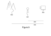
- FIG. 9 is an illustration of a camera and its illustrated objects.
- Embodiments will be exemplified in a non-limiting description.
- the electronic device 600 , 800 may be e.g. a camera, mobile phone, a tablet computer, or any kind of computer.
- the 16 sub-images created by the array camera will show different amount of internal parallax. Those sub-images will contain a lot of redundant information as opposed to a set of just two images.
- the internal parallax of the 16 sub-images holds a rich set of information.
- the internal parallax between the sub-cameras may be used to detect what areas of the combined image that are affected by the misalignment as well as the amount of error. This information may then be used to correct for the problem of occlusion of object or objects by moving the contents of affected areas of the combined image until registration is achieved. Such an action result in occlusion effects (we cannot see behind objects) when using a single lens camera.
- the array camera on the other hand produces a set of sub-images where internal parallax minimizes or eliminates occlusions. Hence, it is possible to detect, measure, and correct for internal parallax caused by misalignment between the first nodal point and the actual rotation center of the camera.
- FIG. 9 schematically illustrates a camera 900 and its illustrated objects.
- the camera is recording a first object 901 and a second object 902 .
- the first object 901 and its adjacent objects (not shown) are placed in a first plane.
- the first plane is placed at a first distance 903 from the camera 900 .
- the second object 902 and its adjacent objects (not shown) are placed in a second plane.
- the second plane is placed at a second distance 904 from the camera 900 .
- the first plane being different from the second plane.
- a combined image may e.g. be a panorama image or a three dimensional image.
- the method comprises the following actions, which actions may be carried out in another suitable order than described below.
- a second set of at least two sub-images recorded by the array of image recording units may be done in the same way as described in relation to action 701 .
- the first set of sub-images and the second set of sub-images are recorded with the array cameras directed in different directions, but it is preferred that there is some overlap between the first set of sub-images and the second set of sub-images.
- a first depth map is calculated for the first set of sub-images.
- the first depth map comprises information about the distance between the illustrated objects in the sub-images and the point where the sub-images have been recorded.
- the first depth map may be created with any method known in the prior art.
- the first depth map comprises information about a first plane of the sub-images and a second plane of the sub-images. The first plane being at a first distance from the point where the sub-images have been recorded, and the second plane being at a second distance from the point where the sub-images have been recorded. These two planes may e.g. represent a foreground and a background in the image.
- the at two planes may be defined using information in the depth map.
- the distance between the first plane to the point where the sub-images have been recorded may be larger than the distance between the second plane and the point where the sub-images have been recorded.
- a second depth map is calculated for the second set of sub-images.
- the second depth map comprises information about the first plane and the second plane.
- the second depth map may be created in the same way as the first depth map. This calculation may be performed in the same way as described in action 703 .
- the first set of sub-images and the second set of sub-images are stitched in the first plane, and thereby obtaining a first stitched image.
- the first set of sub-images and the second set of sub-images are stitched in the second plane, and thereby obtaining a second stitched image.
- This stitching may be performed in the same way as the stitching in action 705 .
- the first set of sub-images and the second set of sub-images may be stitched in the third plane, and thereby obtaining a third stitched image.
- This stitching may be performed in the same way as the stitching in action 705 .
- the first stitched image is combined with the second stitched image and thereby creating the combined image.
- the first stitched image may be combined with the second stitched image.
- the embodiments described here is not limited to that the stitching is performed in two or three planes.
- the calculation of the first depth map and the second depth map may further be based on information about n planes, where n is a natural number.
- the n planes being at n distances from the point where the sub-images have been recorded.
- the first set of sub-images and the second set of sub-images are stitched in the respective n planes, and thereby obtaining n stitched images.
- the first stitched image and the second stitched image is further combined with the n stitched images to produce the combined image.
- the electronic device 800 comprises a first obtaining unit 801 adapted to obtain a first set of at least two sub-images recorded by an array camera.
- the first obtaining unit 801 may also implement all actions described in relation to action 701 above.
- the electronic device 800 also comprises a second obtaining unit 802 adapted to obtain a first set of at least two sub-images recorded by an array camera.
- the second obtaining unit 802 may also implement all actions described in relation to action 702 above.
- the electronic device 800 comprises a first calculation unit 803 adapted to calculate a first depth map for the first set of sub-images.
- the first depth map comprises information about a first plane of the sub-images and a second plane of the sub-images.
- the first plane is at a first distance from the point where the sub-images have been recorded, and the second plane is at a second distance from the point where the sub-images have been recorded.
- the first calculation unit 803 may also implement all actions described in relation to action 703 above.
- the electronic device 800 also comprises a second calculation unit 804 adapted to calculate a second depth map for the second set of sub-images.
- the second depth map comprises information about the first plane and the second plane.
- the second calculation unit 804 may also implement all actions described in relation to action 704 above.
- the electronic device 800 also comprises a second stitching unit 806 adapted to stich the first set of sub-images and the second set of sub-images in the second plane, and thereby obtaining a second stitched image.
- the second stitching unit 806 may also implement all actions described in relation to action 706 above.
- the electronic device 800 also comprises a combining unit 807 adapted to combine the first stitched image with the second stitched image and thereby creating the combined image.
- the combining unit 807 may also implement all actions described in relation to action 708 above.
- the embodiments herein for creating a combined image may be implemented through one or more processors, such as a processing circuit 808 in the electronic device 800 depicted in FIG. 8 , together with computer program code for performing the functions and/or method steps of the embodiments herein.
- the program code mentioned may also be provided as a computer program product, for instance in the form of a data carrier carrying computer program code for performing embodiments herein when being loaded into the electronic device 800 .
- One such carrier may be in the form of a CD ROM disc. It is however feasible with other data carriers such as a memory stick.
- the computer program code may furthermore be provided as pure program code on a server and downloaded to the electronic device 800 .
- first obtaining unit 801 , the second obtaining unit 802 , the first calculating unit 803 , the second calculating unit 804 , the first stitching unit 805 , the second stitching unit 806 and the combining unit 807 described above may refer to a combination of analog and digital circuits, and/or one or more processors configured with software and/or firmware, e.g. stored in a memory, that when executed by the one or more processors.
- processors may be included in a single application-specific integrated circuit (ASIC), or several processors and various digital hardware may be distributed among several separate components, whether individually packaged or assembled into a system-on-a-chip (SoC).
- ASIC application-specific integrated circuit
- SoC system-on-a-chip
Abstract
Description
Claims (15)
Applications Claiming Priority (1)
| Application Number | Priority Date | Filing Date | Title |
|---|---|---|---|
| PCT/EP2012/051571 WO2013113373A1 (en) | 2012-01-31 | 2012-01-31 | Method and electronic device for creating a combined image |
Publications (2)
| Publication Number | Publication Date |
|---|---|
| US20140219581A1 US20140219581A1 (en) | 2014-08-07 |
| US9076269B2 true US9076269B2 (en) | 2015-07-07 |
Family
ID=45833362
Family Applications (1)
| Application Number | Title | Priority Date | Filing Date |
|---|---|---|---|
| US13/813,187 Active US9076269B2 (en) | 2012-01-31 | 2012-01-31 | Method and electronic device for creating a combined image |
Country Status (4)
| Country | Link |
|---|---|
| US (1) | US9076269B2 (en) |
| EP (1) | EP2810247B1 (en) |
| CN (1) | CN104025151B (en) |
| WO (1) | WO2013113373A1 (en) |
Families Citing this family (15)
| Publication number | Priority date | Publication date | Assignee | Title |
|---|---|---|---|---|
| ES2607214T3 (en) * | 2011-05-31 | 2017-03-29 | Nokia Technologies Oy | Methods, devices and software products for generating panoramic images using depth map data |
| EP2810247B1 (en) * | 2012-01-31 | 2018-04-25 | Sony Mobile Communications Inc. | Method and electronic device for creating a combined image |
| CN104205007B (en) * | 2012-03-12 | 2016-11-02 | 索尼移动通讯有限公司 | The electronic installation of content for the occlusion area of display window |
| US9303982B1 (en) * | 2013-05-08 | 2016-04-05 | Amazon Technologies, Inc. | Determining object depth information using image data |
| CA2848794C (en) * | 2014-04-11 | 2016-05-24 | Blackberry Limited | Building a depth map using movement of one camera |
| JP6317635B2 (en) * | 2014-06-30 | 2018-04-25 | 株式会社東芝 | Image processing apparatus, image processing method, and image processing program |
| CN105574838B (en) * | 2014-10-15 | 2018-09-14 | 上海弘视通信技术有限公司 | The image registration of more mesh cameras and joining method and its device |
| US9818198B2 (en) * | 2014-10-21 | 2017-11-14 | University Of Louisiana At Lafayette | Method for near-realtime workspace mapping |
| EP3341826B1 (en) | 2015-09-30 | 2022-06-22 | Hewlett-Packard Development Company, L.P. | Interactive display system |
| US10085006B2 (en) * | 2016-09-08 | 2018-09-25 | Samsung Electronics Co., Ltd. | Three hundred sixty degree video stitching |
| CN107360354B (en) * | 2017-07-31 | 2020-06-26 | Oppo广东移动通信有限公司 | Photographing method, photographing device, mobile terminal and computer-readable storage medium |
| CN107818589A (en) * | 2017-11-08 | 2018-03-20 | 深圳岚锋创视网络科技有限公司 | A kind of generation method, system and the portable terminal of distant view photograph wall |
| US11030718B1 (en) * | 2019-12-05 | 2021-06-08 | Vivotek Inc. | Image stitching method and related monitoring camera apparatus |
| CN112422830B (en) * | 2020-11-19 | 2022-04-19 | 亿咖通(湖北)技术有限公司 | Method and device for acquiring vehicle panoramic image and computer storage medium |
| DE102022125210A1 (en) * | 2022-09-29 | 2024-04-04 | Bayerische Motoren Werke Aktiengesellschaft | Combining partial images of a vehicle environment |
Citations (8)
| Publication number | Priority date | Publication date | Assignee | Title |
|---|---|---|---|---|
| US6487304B1 (en) * | 1999-06-16 | 2002-11-26 | Microsoft Corporation | Multi-view approach to motion and stereo |
| EP2385705A1 (en) | 2008-12-30 | 2011-11-09 | Huawei Device Co., Ltd. | Method and device for generating stereoscopic panoramic video stream, and method and device of video conference |
| US8131062B2 (en) * | 2003-03-29 | 2012-03-06 | Atelier Vision Limited | Method of processing an image |
| US20120069320A1 (en) * | 2009-01-09 | 2012-03-22 | Asmr Holding B.V. | Optical rangefinder and imaging apparatus with chiral optical arrangement |
| US8411934B2 (en) * | 2007-11-09 | 2013-04-02 | Thomson Licensing | System and method for depth map extraction using region-based filtering |
| US20130101263A1 (en) * | 2010-08-31 | 2013-04-25 | Panasonic Corporation | Image capture device, player, system, and image processing method |
| US20130156294A1 (en) * | 2011-12-15 | 2013-06-20 | Sony Corporation | Depth map generation based on soft classification |
| US20140219581A1 (en) * | 2012-01-31 | 2014-08-07 | Sony Mobile Communications Ab | Method and electronic device for creating a combined image |
Family Cites Families (8)
| Publication number | Priority date | Publication date | Assignee | Title |
|---|---|---|---|---|
| GB9011922D0 (en) * | 1990-05-29 | 1990-07-18 | Europ Vision Syst Centre | Machine vision stereo matching |
| CN100458559C (en) * | 2003-06-23 | 2009-02-04 | 宋柏君 | Stereoscopic digital camera and imaging display method |
| US7499586B2 (en) * | 2005-10-04 | 2009-03-03 | Microsoft Corporation | Photographing big things |
| US8456515B2 (en) * | 2006-07-25 | 2013-06-04 | Qualcomm Incorporated | Stereo image and video directional mapping of offset |
| US8189100B2 (en) * | 2006-07-25 | 2012-05-29 | Qualcomm Incorporated | Mobile device with dual digital camera sensors and methods of using the same |
| CN101673395B (en) * | 2008-09-10 | 2012-09-05 | 华为终端有限公司 | Image mosaic method and image mosaic device |
| CN101771830B (en) * | 2008-12-30 | 2012-09-19 | 华为终端有限公司 | Three-dimensional panoramic video stream generating method and equipment and video conference method and equipment |
| CN101577795A (en) * | 2009-06-17 | 2009-11-11 | 深圳华为通信技术有限公司 | Method and device for realizing real-time viewing of panoramic picture |
-
2012
- 2012-01-31 EP EP12708777.3A patent/EP2810247B1/en active Active
- 2012-01-31 WO PCT/EP2012/051571 patent/WO2013113373A1/en active Application Filing
- 2012-01-31 CN CN201280065569.5A patent/CN104025151B/en active Active
- 2012-01-31 US US13/813,187 patent/US9076269B2/en active Active
Patent Citations (8)
| Publication number | Priority date | Publication date | Assignee | Title |
|---|---|---|---|---|
| US6487304B1 (en) * | 1999-06-16 | 2002-11-26 | Microsoft Corporation | Multi-view approach to motion and stereo |
| US8131062B2 (en) * | 2003-03-29 | 2012-03-06 | Atelier Vision Limited | Method of processing an image |
| US8411934B2 (en) * | 2007-11-09 | 2013-04-02 | Thomson Licensing | System and method for depth map extraction using region-based filtering |
| EP2385705A1 (en) | 2008-12-30 | 2011-11-09 | Huawei Device Co., Ltd. | Method and device for generating stereoscopic panoramic video stream, and method and device of video conference |
| US20120069320A1 (en) * | 2009-01-09 | 2012-03-22 | Asmr Holding B.V. | Optical rangefinder and imaging apparatus with chiral optical arrangement |
| US20130101263A1 (en) * | 2010-08-31 | 2013-04-25 | Panasonic Corporation | Image capture device, player, system, and image processing method |
| US20130156294A1 (en) * | 2011-12-15 | 2013-06-20 | Sony Corporation | Depth map generation based on soft classification |
| US20140219581A1 (en) * | 2012-01-31 | 2014-08-07 | Sony Mobile Communications Ab | Method and electronic device for creating a combined image |
Non-Patent Citations (2)
| Title |
|---|
| International Search Report and Written Opinion dated Oct. 26, 2012 issued in corresponding PCT application No. PCT/EP2012/051571, 13 pages. |
| Soon-Young Lee; Panoramic Scene Generation Form Multi-View Images with Close Foreground Objects; 28th Picture Coding Symposium; Dec. 8-10, 2010; Nagoya, Japan, pp. 486-489. |
Also Published As
| Publication number | Publication date |
|---|---|
| CN104025151A (en) | 2014-09-03 |
| WO2013113373A1 (en) | 2013-08-08 |
| US20140219581A1 (en) | 2014-08-07 |
| EP2810247A1 (en) | 2014-12-10 |
| EP2810247B1 (en) | 2018-04-25 |
| CN104025151B (en) | 2018-08-28 |
Similar Documents
| Publication | Publication Date | Title |
|---|---|---|
| US9076269B2 (en) | Method and electronic device for creating a combined image | |
| US9774837B2 (en) | System for performing distortion correction and calibration using pattern projection, and method using the same | |
| US20200288059A1 (en) | Image processor, image processing method and program, and imaging system | |
| US11631155B2 (en) | Equatorial stitching of hemispherical images in a spherical image capture system | |
| JP5924978B2 (en) | Image processing apparatus and image processing method | |
| US9576403B2 (en) | Method and apparatus for fusion of images | |
| JP2012174116A (en) | Object display device, object display method and object display program | |
| US10027949B2 (en) | Image processing apparatus, image processing method, and recording medium | |
| CN105791695B (en) | The generation method and device of panoramic picture | |
| CN110049246A (en) | Video anti-fluttering method, device and the electronic equipment of electronic equipment | |
| KR20180137916A (en) | Virtual reality image contents providing system and thereof providing method | |
| JP2014215755A (en) | Image processing system, image processing apparatus, and image processing method | |
| EP3216005B1 (en) | Image processing device and method for geometric calibration of images | |
| KR20190086320A (en) | The apparatus for proccesing image and method therefor | |
| JP6089742B2 (en) | Image processing apparatus, imaging apparatus, image processing method, and program | |
| JP5791534B2 (en) | Photo mapping system | |
| JP5885974B2 (en) | Corresponding point setting method, corresponding point setting device, and corresponding point setting program for aerial photo image data | |
| WO2015019208A1 (en) | Apparatus and method for correcting perspective distortions of images | |
| JP4757679B2 (en) | Video composition device | |
| CN113344789A (en) | Image splicing method and device, electronic equipment and computer readable storage medium | |
| KR102074072B1 (en) | A focus-context display techinique and apparatus using a mobile device with a dual camera | |
| JP2013120477A (en) | Image display device, image display method, and program | |
| JPWO2018180213A1 (en) | Image correction device, image correction method, and program | |
| JP5620871B2 (en) | Panorama image data generation device | |
| TWI466535B (en) | Three-dimensional imaging method using single-lens mage-capture apparatus, and three-dimensional image enhancement method and three-dimensional image enhancement apparatus based on first and second two-dimensional images for three-dimensional image displ |
Legal Events
| Date | Code | Title | Description |
|---|---|---|---|
| AS | Assignment |
Owner name: SONY MOBILE COMMUNICATIONS AB, SWEDEN Free format text: ASSIGNMENT OF ASSIGNORS INTEREST;ASSIGNORS:ASTRAND, PER;LANDQVIST, MAGNUS;THORN, KARL OLA;AND OTHERS;SIGNING DATES FROM 20130114 TO 20130121;REEL/FRAME:029719/0370 |
|
| AS | Assignment |
Owner name: SONY CORPORATION, JAPAN Free format text: ASSIGNMENT OF ASSIGNORS INTEREST;ASSIGNOR:SONY MOBILE COMMUNICATIONS AB;REEL/FRAME:035766/0518 Effective date: 20150512 Owner name: SONY MOBILE COMMUNICATIONS AB, SWEDEN Free format text: ASSIGNMENT OF ASSIGNORS INTEREST;ASSIGNOR:SONY MOBILE COMMUNICATIONS AB;REEL/FRAME:035766/0518 Effective date: 20150512 |
|
| STCF | Information on status: patent grant |
Free format text: PATENTED CASE |
|
| AS | Assignment |
Owner name: SONY MOBILE COMMUNICATIONS INC., JAPAN Free format text: ASSIGNMENT OF ASSIGNORS INTEREST;ASSIGNOR:SONY CORPORATION;REEL/FRAME:043943/0631 Effective date: 20170914 |
|
| AS | Assignment |
Owner name: SONY MOBILE COMMUNICATIONS INC., JAPAN Free format text: ASSIGNMENT OF ASSIGNORS INTEREST;ASSIGNOR:SONY MOBILE COMMUNICATIONS AB;REEL/FRAME:043951/0529 Effective date: 20170912 |
|
| MAFP | Maintenance fee payment |
Free format text: PAYMENT OF MAINTENANCE FEE, 4TH YEAR, LARGE ENTITY (ORIGINAL EVENT CODE: M1551); ENTITY STATUS OF PATENT OWNER: LARGE ENTITY Year of fee payment: 4 |
|
| AS | Assignment |
Owner name: SONY CORPORATION, JAPAN Free format text: ASSIGNMENT OF ASSIGNORS INTEREST;ASSIGNOR:SONY MOBILE COMMUNICATIONS, INC.;REEL/FRAME:048691/0134 Effective date: 20190325 |
|
| MAFP | Maintenance fee payment |
Free format text: PAYMENT OF MAINTENANCE FEE, 8TH YEAR, LARGE ENTITY (ORIGINAL EVENT CODE: M1552); ENTITY STATUS OF PATENT OWNER: LARGE ENTITY Year of fee payment: 8 |