US9076338B2 - Travel control plan generation system and computer program - Google Patents

Travel control plan generation system and computer program Download PDF

Info

Publication number
US9076338B2
US9076338B2 US12/515,391 US51539107A US9076338B2 US 9076338 B2 US9076338 B2 US 9076338B2 US 51539107 A US51539107 A US 51539107A US 9076338 B2 US9076338 B2 US 9076338B2
Authority
US
United States
Prior art keywords
plan
lower level
vehicle
level plan
travel
Prior art date
Legal status (The legal status is an assumption and is not a legal conclusion. Google has not performed a legal analysis and makes no representation as to the accuracy of the status listed.)
Active, expires
Application number
US12/515,391
Other versions
US20100042282A1 (en
Inventor
Koji Taguchi
Makoto Aso
Current Assignee (The listed assignees may be inaccurate. Google has not performed a legal analysis and makes no representation or warranty as to the accuracy of the list.)
Toyota Motor Corp
Original Assignee
Toyota Motor Corp
Priority date (The priority date is an assumption and is not a legal conclusion. Google has not performed a legal analysis and makes no representation as to the accuracy of the date listed.)
Filing date
Publication date
Application filed by Toyota Motor Corp filed Critical Toyota Motor Corp
Assigned to TOYOTA JIDOSHA KABUSHIKI KAISHA reassignment TOYOTA JIDOSHA KABUSHIKI KAISHA ASSIGNMENT OF ASSIGNORS INTEREST (SEE DOCUMENT FOR DETAILS). Assignors: ASO, MAKOTO, TAGUCHI, KOJI
Publication of US20100042282A1 publication Critical patent/US20100042282A1/en
Application granted granted Critical
Publication of US9076338B2 publication Critical patent/US9076338B2/en
Active legal-status Critical Current
Adjusted expiration legal-status Critical

Links

Images

Classifications

    • GPHYSICS
    • G08SIGNALLING
    • G08GTRAFFIC CONTROL SYSTEMS
    • G08G1/00Traffic control systems for road vehicles
    • G08G1/16Anti-collision systems
    • G08G1/161Decentralised systems, e.g. inter-vehicle communication
    • BPERFORMING OPERATIONS; TRANSPORTING
    • B60VEHICLES IN GENERAL
    • B60WCONJOINT CONTROL OF VEHICLE SUB-UNITS OF DIFFERENT TYPE OR DIFFERENT FUNCTION; CONTROL SYSTEMS SPECIALLY ADAPTED FOR HYBRID VEHICLES; ROAD VEHICLE DRIVE CONTROL SYSTEMS FOR PURPOSES NOT RELATED TO THE CONTROL OF A PARTICULAR SUB-UNIT
    • B60W30/00Purposes of road vehicle drive control systems not related to the control of a particular sub-unit, e.g. of systems using conjoint control of vehicle sub-units, or advanced driver assistance systems for ensuring comfort, stability and safety or drive control systems for propelling or retarding the vehicle
    • B60W30/10Path keeping
    • B60W30/12Lane keeping
    • BPERFORMING OPERATIONS; TRANSPORTING
    • B60VEHICLES IN GENERAL
    • B60WCONJOINT CONTROL OF VEHICLE SUB-UNITS OF DIFFERENT TYPE OR DIFFERENT FUNCTION; CONTROL SYSTEMS SPECIALLY ADAPTED FOR HYBRID VEHICLES; ROAD VEHICLE DRIVE CONTROL SYSTEMS FOR PURPOSES NOT RELATED TO THE CONTROL OF A PARTICULAR SUB-UNIT
    • B60W50/00Details of control systems for road vehicle drive control not related to the control of a particular sub-unit, e.g. process diagnostic or vehicle driver interfaces
    • B60W50/08Interaction between the driver and the control system
    • B60W50/14Means for informing the driver, warning the driver or prompting a driver intervention
    • BPERFORMING OPERATIONS; TRANSPORTING
    • B60VEHICLES IN GENERAL
    • B60WCONJOINT CONTROL OF VEHICLE SUB-UNITS OF DIFFERENT TYPE OR DIFFERENT FUNCTION; CONTROL SYSTEMS SPECIALLY ADAPTED FOR HYBRID VEHICLES; ROAD VEHICLE DRIVE CONTROL SYSTEMS FOR PURPOSES NOT RELATED TO THE CONTROL OF A PARTICULAR SUB-UNIT
    • B60W10/00Conjoint control of vehicle sub-units of different type or different function
    • B60W10/04Conjoint control of vehicle sub-units of different type or different function including control of propulsion units
    • B60W10/06Conjoint control of vehicle sub-units of different type or different function including control of propulsion units including control of combustion engines
    • BPERFORMING OPERATIONS; TRANSPORTING
    • B60VEHICLES IN GENERAL
    • B60WCONJOINT CONTROL OF VEHICLE SUB-UNITS OF DIFFERENT TYPE OR DIFFERENT FUNCTION; CONTROL SYSTEMS SPECIALLY ADAPTED FOR HYBRID VEHICLES; ROAD VEHICLE DRIVE CONTROL SYSTEMS FOR PURPOSES NOT RELATED TO THE CONTROL OF A PARTICULAR SUB-UNIT
    • B60W10/00Conjoint control of vehicle sub-units of different type or different function
    • B60W10/18Conjoint control of vehicle sub-units of different type or different function including control of braking systems
    • B60W10/184Conjoint control of vehicle sub-units of different type or different function including control of braking systems with wheel brakes
    • BPERFORMING OPERATIONS; TRANSPORTING
    • B60VEHICLES IN GENERAL
    • B60WCONJOINT CONTROL OF VEHICLE SUB-UNITS OF DIFFERENT TYPE OR DIFFERENT FUNCTION; CONTROL SYSTEMS SPECIALLY ADAPTED FOR HYBRID VEHICLES; ROAD VEHICLE DRIVE CONTROL SYSTEMS FOR PURPOSES NOT RELATED TO THE CONTROL OF A PARTICULAR SUB-UNIT
    • B60W10/00Conjoint control of vehicle sub-units of different type or different function
    • B60W10/20Conjoint control of vehicle sub-units of different type or different function including control of steering systems
    • BPERFORMING OPERATIONS; TRANSPORTING
    • B60VEHICLES IN GENERAL
    • B60WCONJOINT CONTROL OF VEHICLE SUB-UNITS OF DIFFERENT TYPE OR DIFFERENT FUNCTION; CONTROL SYSTEMS SPECIALLY ADAPTED FOR HYBRID VEHICLES; ROAD VEHICLE DRIVE CONTROL SYSTEMS FOR PURPOSES NOT RELATED TO THE CONTROL OF A PARTICULAR SUB-UNIT
    • B60W2510/00Input parameters relating to a particular sub-units
    • B60W2510/20Steering systems
    • B60W2510/202Steering torque
    • B60W2550/20
    • B60W2550/30
    • B60W2550/306
    • B60W2550/402
    • BPERFORMING OPERATIONS; TRANSPORTING
    • B60VEHICLES IN GENERAL
    • B60WCONJOINT CONTROL OF VEHICLE SUB-UNITS OF DIFFERENT TYPE OR DIFFERENT FUNCTION; CONTROL SYSTEMS SPECIALLY ADAPTED FOR HYBRID VEHICLES; ROAD VEHICLE DRIVE CONTROL SYSTEMS FOR PURPOSES NOT RELATED TO THE CONTROL OF A PARTICULAR SUB-UNIT
    • B60W2554/00Input parameters relating to objects
    • B60W2554/40Dynamic objects, e.g. animals, windblown objects
    • B60W2554/404Characteristics
    • B60W2554/4041Position
    • BPERFORMING OPERATIONS; TRANSPORTING
    • B60VEHICLES IN GENERAL
    • B60WCONJOINT CONTROL OF VEHICLE SUB-UNITS OF DIFFERENT TYPE OR DIFFERENT FUNCTION; CONTROL SYSTEMS SPECIALLY ADAPTED FOR HYBRID VEHICLES; ROAD VEHICLE DRIVE CONTROL SYSTEMS FOR PURPOSES NOT RELATED TO THE CONTROL OF A PARTICULAR SUB-UNIT
    • B60W2554/00Input parameters relating to objects
    • B60W2554/40Dynamic objects, e.g. animals, windblown objects
    • B60W2554/404Characteristics
    • B60W2554/4042Longitudinal speed
    • BPERFORMING OPERATIONS; TRANSPORTING
    • B60VEHICLES IN GENERAL
    • B60WCONJOINT CONTROL OF VEHICLE SUB-UNITS OF DIFFERENT TYPE OR DIFFERENT FUNCTION; CONTROL SYSTEMS SPECIALLY ADAPTED FOR HYBRID VEHICLES; ROAD VEHICLE DRIVE CONTROL SYSTEMS FOR PURPOSES NOT RELATED TO THE CONTROL OF A PARTICULAR SUB-UNIT
    • B60W2554/00Input parameters relating to objects
    • B60W2554/40Dynamic objects, e.g. animals, windblown objects
    • B60W2554/404Characteristics
    • B60W2554/4049Relationship among other objects, e.g. converging dynamic objects
    • BPERFORMING OPERATIONS; TRANSPORTING
    • B60VEHICLES IN GENERAL
    • B60WCONJOINT CONTROL OF VEHICLE SUB-UNITS OF DIFFERENT TYPE OR DIFFERENT FUNCTION; CONTROL SYSTEMS SPECIALLY ADAPTED FOR HYBRID VEHICLES; ROAD VEHICLE DRIVE CONTROL SYSTEMS FOR PURPOSES NOT RELATED TO THE CONTROL OF A PARTICULAR SUB-UNIT
    • B60W2554/00Input parameters relating to objects
    • B60W2554/80Spatial relation or speed relative to objects
    • BPERFORMING OPERATIONS; TRANSPORTING
    • B60VEHICLES IN GENERAL
    • B60WCONJOINT CONTROL OF VEHICLE SUB-UNITS OF DIFFERENT TYPE OR DIFFERENT FUNCTION; CONTROL SYSTEMS SPECIALLY ADAPTED FOR HYBRID VEHICLES; ROAD VEHICLE DRIVE CONTROL SYSTEMS FOR PURPOSES NOT RELATED TO THE CONTROL OF A PARTICULAR SUB-UNIT
    • B60W2556/00Input parameters relating to data
    • B60W2556/45External transmission of data to or from the vehicle
    • B60W2556/50External transmission of data to or from the vehicle for navigation systems
    • BPERFORMING OPERATIONS; TRANSPORTING
    • B60VEHICLES IN GENERAL
    • B60WCONJOINT CONTROL OF VEHICLE SUB-UNITS OF DIFFERENT TYPE OR DIFFERENT FUNCTION; CONTROL SYSTEMS SPECIALLY ADAPTED FOR HYBRID VEHICLES; ROAD VEHICLE DRIVE CONTROL SYSTEMS FOR PURPOSES NOT RELATED TO THE CONTROL OF A PARTICULAR SUB-UNIT
    • B60W30/00Purposes of road vehicle drive control systems not related to the control of a particular sub-unit, e.g. of systems using conjoint control of vehicle sub-units, or advanced driver assistance systems for ensuring comfort, stability and safety or drive control systems for propelling or retarding the vehicle
    • B60W30/14Adaptive cruise control
    • B60W30/143Speed control
    • BPERFORMING OPERATIONS; TRANSPORTING
    • B60VEHICLES IN GENERAL
    • B60WCONJOINT CONTROL OF VEHICLE SUB-UNITS OF DIFFERENT TYPE OR DIFFERENT FUNCTION; CONTROL SYSTEMS SPECIALLY ADAPTED FOR HYBRID VEHICLES; ROAD VEHICLE DRIVE CONTROL SYSTEMS FOR PURPOSES NOT RELATED TO THE CONTROL OF A PARTICULAR SUB-UNIT
    • B60W30/00Purposes of road vehicle drive control systems not related to the control of a particular sub-unit, e.g. of systems using conjoint control of vehicle sub-units, or advanced driver assistance systems for ensuring comfort, stability and safety or drive control systems for propelling or retarding the vehicle
    • B60W30/14Adaptive cruise control
    • B60W30/16Control of distance between vehicles, e.g. keeping a distance to preceding vehicle
    • BPERFORMING OPERATIONS; TRANSPORTING
    • B60VEHICLES IN GENERAL
    • B60WCONJOINT CONTROL OF VEHICLE SUB-UNITS OF DIFFERENT TYPE OR DIFFERENT FUNCTION; CONTROL SYSTEMS SPECIALLY ADAPTED FOR HYBRID VEHICLES; ROAD VEHICLE DRIVE CONTROL SYSTEMS FOR PURPOSES NOT RELATED TO THE CONTROL OF A PARTICULAR SUB-UNIT
    • B60W40/00Estimation or calculation of non-directly measurable driving parameters for road vehicle drive control systems not related to the control of a particular sub unit, e.g. by using mathematical models
    • B60W40/02Estimation or calculation of non-directly measurable driving parameters for road vehicle drive control systems not related to the control of a particular sub unit, e.g. by using mathematical models related to ambient conditions
    • B60W40/06Road conditions
    • B60W40/072Curvature of the road
    • BPERFORMING OPERATIONS; TRANSPORTING
    • B60VEHICLES IN GENERAL
    • B60WCONJOINT CONTROL OF VEHICLE SUB-UNITS OF DIFFERENT TYPE OR DIFFERENT FUNCTION; CONTROL SYSTEMS SPECIALLY ADAPTED FOR HYBRID VEHICLES; ROAD VEHICLE DRIVE CONTROL SYSTEMS FOR PURPOSES NOT RELATED TO THE CONTROL OF A PARTICULAR SUB-UNIT
    • B60W40/00Estimation or calculation of non-directly measurable driving parameters for road vehicle drive control systems not related to the control of a particular sub unit, e.g. by using mathematical models
    • B60W40/02Estimation or calculation of non-directly measurable driving parameters for road vehicle drive control systems not related to the control of a particular sub unit, e.g. by using mathematical models related to ambient conditions
    • B60W40/06Road conditions
    • B60W40/076Slope angle of the road

Definitions

  • the present invention relates to a travel control plan generating system and a computer program for generating a travel control plan for an automatically driven vehicle.
  • Japanese Unexamined Patent Application No. 2004-182149 discloses an apparatus for controlling automatic driving of a vehicle.
  • a target deceleration is determined on the basis of a relative speed and a relative distance of a home vehicle to an obstacle ahead, and a braking force is controlled automatically such that an actual deceleration matches the target deceleration.
  • the control policy of the home vehicle is determined from the relative speed and relative distance to a peripheral vehicle, i.e. state parameters of the home vehicle at a certain moment, and therefore the home vehicle can only respond to variation in the conditions (acceleration/deceleration, lateral position, and so on) of the peripheral vehicle after the variation has actually occurred. As a result, so-called consequential control is performed. Hence, it is difficult to respond to condition variation with sufficient leeway and the response in such cases is limited, and therefore, depending on the response, control that contravenes the travel policy of the home vehicle in terms of comfort and fuel efficiency may be performed.
  • the present invention has been designed in consideration of the circumstances described above, and provides a travel control plan generating system and a computer program capable of responding flexibly to variation in the conditions of a peripheral environment while satisfying a travel policy of a home vehicle.
  • a travel control plan generating system includes: upper level plan generating means for generating an upper level plan corresponding to a travel policy of a vehicle; lower level plan generating means for generating a lower level plan, which is a plan for achieving the upper level plan and includes at least a travel course; lower level plan obtaining means for obtaining a lower level plan including at least a travel course of a peripheral vehicle of the vehicle; evaluating means for evaluating the lower level plan of the vehicle in accordance with a predetermined index, taking into account the lower level plan of the peripheral vehicle; and lower level plan selecting means for selecting a lower level plan to be executed by the vehicle on the basis of an evaluation performed by the evaluating means.
  • an upper level plan corresponding to the travel policy of the vehicle can be generated, and a lower level plan for achieving the upper level plan can be generated.
  • the lower level plan includes at least a travel course, and the lower level plan of the vehicle can be evaluated taking into account the lower level plan of the peripheral vehicle, whereby the lower level plan to be executed can be selected in accordance with the evaluation.
  • the lower level plan can be selected on the basis of an evaluation performed in accordance with a predetermined index (for example, safety, comfort, environmental considerations (based on fuel efficiency and the like), and so on), and therefore the vehicle can be controlled on the basis of an appropriate plan corresponding to predetermined conditions.
  • a predetermined index for example, safety, comfort, environmental considerations (based on fuel efficiency and the like), and so on
  • the lower level plan generating means may generate a plurality of lower level plans for the vehicle, and the lower level plan selecting means may select the lower level plan to be executed from the plurality of lower level plans on the basis of the evaluation performed by the evaluating means.
  • the vehicle can be controlled on the basis of an appropriate plan corresponding to predetermined conditions.
  • the upper level plan generating means may regenerate the upper level plan when the lower level plan cannot be generated. Further, the upper level plan generating means may regenerate the upper level plan in accordance with the evaluation performed by the evaluating means. Hence, when a lower level plan cannot be generated or the predetermined index cannot be satisfied sufficiently, the upper level plan can be reconsidered.
  • the lower level plan generating means may include inferring means for inferring the lower level plan of the peripheral vehicle on the basis of a behavior of the peripheral vehicle, and the lower level plan of the peripheral vehicle may be obtained from an inference by the inferring means.
  • inferring means for inferring the lower level plan of the peripheral vehicle on the basis of a behavior of the peripheral vehicle, and the lower level plan of the peripheral vehicle may be obtained from an inference by the inferring means.
  • the lower level plan obtaining means may include communicating means for communicating with the peripheral vehicle, and the lower level plan of the peripheral vehicle may be obtained through communication performed by the communicating means.
  • the lower level plan of an automatically driven vehicle sewing as a peripheral vehicle having a travel control plan and the lower level plan of a peripheral vehicle of the automatically driven vehicle, which is inferred in the automatically driven vehicle can be obtained through communication.
  • the evaluating means may evaluate the lower level plan of the vehicle taking into account a reliability of the lower level plan of the peripheral vehicle.
  • the lower level plan of the peripheral vehicle is generated by an automatically driven vehicle and inferred in relation to a manually driven vehicle, and therefore the respective reliability levels of the lower level plans are different. Hence, by taking reliability into consideration while evaluating the lower level plan of the vehicle, the vehicle can be subjected to travel control on the basis of a more appropriate plan.
  • the reliability of a lower level plan obtained from the inferring means may be set lower than the reliability of a lower level plan of an automatically driven vehicle obtained from the communicating means.
  • the lower level plan may include a speed pattern of the vehicle.
  • longitudinal direction control corresponding to the speed pattern can be set as a control target in addition to lateral direction control corresponding to the travel course.
  • a computer program causes a computer to execute: an upper level plan generating step for generating an upper level plan corresponding to a travel policy of a vehicle; a lower level plan generating step for generating a lower level plan, which is a plan for achieving the upper level plan and includes at least a travel course; a lower level plan obtaining step for obtaining a lower level plan including at least a travel course of a peripheral vehicle of the vehicle; an evaluating step for evaluating the lower level plan of the vehicle in accordance with a predetermined index, taking into account the lower level plan of the peripheral vehicle; and a lower level plan selecting step for selecting a lower level plan to be executed by the vehicle on the basis of an evaluation performed in the evaluating step.
  • the computer can be caused to function as a travel control plan generating system that can respond flexibly to variation in the conditions of a peripheral environment while satisfying a travel policy of a home vehicle.
  • FIG. 1 is a block diagram showing the constitution of an automatically driven vehicle A installed with a travel control plan generating system according to an embodiment
  • FIG. 2 is a view showing a flow of multi-layer travel control plan generation
  • FIG. 3 is a view showing positional relationships between a vehicle A and peripheral vehicles B, C;
  • FIG. 4 is a view showing a lower level plan of the peripheral vehicle B and a behavior prediction (lower level plan) of the vehicle C;
  • FIG. 5 is a flowchart of lower level plan generation when a lane change is planned
  • FIG. 6 is a view illustrating evaluation and selection of a lower level plan of the vehicle A
  • FIG. 7 is a block diagram showing a modified example of the constitution of the automatically driven vehicle A installed with the travel control plan generating system.
  • FIG. 8 is a view illustrating optimum control during vehicle convergence.
  • a travel control plan generating system (also referred to simply as a “generating system” hereafter) according to this embodiment is formed using hardware of a microcomputer such as an ECU (Electronic Control Unit) and software, and is installed in an automatically driven and controlled vehicle A. As shown in FIG.
  • the generating system 1 includes a peripheral vehicle recognition unit 12 , a home vehicle state quantity estimation unit 14 , a peripheral vehicle behavior prediction unit (lower level plan obtaining means, inferring means) 16 , a vehicle group all-vehicle behavior prediction correction unit 18 , a condition setting input unit 20 , a travel control plan generation unit (upper level plan generating means, lower level plan generating means) 22 , an evaluation unit (evaluating means) 24 , a lower level plan selection unit (lower level plan selecting means) 26 , a transmission unit 28 , and a reception unit (lower level plan obtaining means, communicating means) 30 .
  • the peripheral vehicle recognition unit 12 is connected to a periphery sensor 32 that performs peripheral monitoring, such as a millimeter wave radar, an image sensor, a laser radar, or an ultrasonic wave sensor.
  • the peripheral vehicle recognition unit 12 recognizes a peripheral vehicle C (here, a non-communicative vehicle C that is driven manually and does not have a, communication function) existing on the periphery of the vehicle A (also referred to as a home vehicle) on the basis of a detection value (reflection information from a peripheral object such as a vehicle, for example) from the periphery sensor 32 , and calculates peripheral vehicle information such as a relative distance, a relative speed, and a relative angle from the home vehicle A.
  • the home vehicle state estimation unit 14 is connected to a home vehicle sensor 34 that detects a home vehicle's state.
  • the home vehicle sensor 34 include a yaw rate sensor, a vehicle speed sensor an acceleration sensor, a steering angle sensor, a white line detection sensor, and a GPS.
  • the home vehicle state estimation unit 14 calculates a state estimated value (a yaw rate, a lateral position within a lane, a lateral velocity, a yaw angle relative to a road shape, a home vehicle position, and so on) of the vehicle A at a corresponding point in time using a vehicle model incorporated into the software.
  • the peripheral vehicle behavior prediction unit 16 obtains the peripheral vehicle information calculated by the peripheral vehicle recognition unit 12 and the state estimation value of the vehicle A calculated by the home vehicle state estimation unit 14 . From the obtained information, the peripheral vehicle behavior prediction unit 16 calculates a position information history of the vehicle A, a relative position information history and a relative speed of the peripheral vehicle C, and so on, and estimates the position information history and current conditions (speed, acceleration, yaw angle relative to the road alignment, and so on) of the peripheral vehicle C from this information. Thus, the positional relationships of the peripheral vehicle C and the tendencies of the peripheral vehicle C (driver preferences such as inter-vehicle distance, vehicle speed, acceleration, and willingness to change lanes) can be estimated.
  • the peripheral vehicle behavior prediction unit 16 also obtains traveling road information (lane number increases/decreases, convergence, forks, shape, curbs, and so on) from a navigation system, infrastructure facilities, and so on. Then, on the basis of the position information history and current conditions of the peripheral vehicle C and the road information, the peripheral vehicle behavior prediction unit 16 tentatively predicts the future (for example, within approximately several hundred meters) behavior (including a travel course and a speed pattern) of the peripheral vehicle C as a lower level plan of the peripheral vehicle C from the tendencies of the peripheral vehicle C and in accordance with a driver model generated in advance.
  • traveling road information latitude increases/decreases, convergence, forks, shape, curbs, and so on
  • the peripheral vehicle behavior prediction unit 16 tentatively predicts the future (for example, within approximately several hundred meters) behavior (including a travel course and a speed pattern) of the peripheral vehicle C as a lower level plan of the peripheral vehicle C from the tendencies of the peripheral vehicle C and in accordance with a driver model generated in advance.
  • the reception unit 30 obtains a travel control plan for another automatically driven vehicle B, which is generated by the vehicle B, through inter-vehicle communication using radio waves of 2.4 GHz or the like.
  • the travel control plan includes a similar upper level plan, to be described below, to that of the vehicle A, and a lower level plan including a travel course and a speed pattern.
  • the vehicle group all-vehicle behavior prediction correction unit 18 obtains the lower level plan of the vehicle A, which is selected by the lower level plan selection unit 26 , and also obtains the lower level plan of the vehicle B from the reception unit 30 and the behavior prediction (lower level plan) of the vehicle C from the peripheral vehicle behavior prediction unit 16 .
  • the vehicle group all-vehicle behavior prediction correction unit 18 then corrects the lower level plans of the respective vehicles such that mismatch points (when two vehicles overlap or the like) are eliminated by overlapping the plans on a temporal axis.
  • the condition setting input unit 20 receives input of overall travel conditions to a destination specified by the driver, for example the destination) desired travel time, fuel efficiency precedence, rest plans, and so on.
  • the travel control plan generation unit 22 includes an upper level plan generation unit (upper level plan generating means) 22 a and a lower level plan generation unit (lower level plan generating means) 22 b .
  • the upper level plan generation unit 22 a dynamically generates a travel plan in units of several tens of km and several tens of minutes extending between interchanges IC or service areas/parking areas SAPA, taking into consideration overall travel conditions, which are set in units of several hundred km and several hours to the destination specified by the driver, travel environment conditions such as navigation information and infrastructure information, and so on.
  • the travel plan includes the travel time, travel plan policies (rest frequency, fuel efficiency, other vehicle precedence, and so on), vehicle group organization, and so on.
  • a route search to the destination is performed, and a plurality of candidate routes is selected.
  • An optimum route satisfying traffic information, the desired travel time, and the travel plan policies is then selected.
  • the entire route is then divided into units of ICs or SAPAs, and a travel plan is determined for each section.
  • a vehicle group organization policy plan is also determined as a travel plan.
  • a vehicle group organization policy plan a plurality of automatically driven vehicles are organized into a vehicle group such that starts and stops can be performed en masse, thereby reducing repeated unnecessary starts and stops during travel through congestion, for example.
  • the upper level plan generation unit 22 a dynamically generates an event transition plan in units of several hundred meters and several tens of seconds from each point in time on the basis of the travel plan generated as described above, recognition of the peripheral conditions (based on the periphery sensor 32 , infrastructure monitoring information, etc.), and so on.
  • the event transition plan includes a lane change (a completion target point, a desired lane change time (degree of urgency), a minimum allowable lane change time (during emergency avoidance or the like), whether the lane change is necessary or required for emergency avoidance, the probability of returning to the original lane, and so on), an upper limit speed modification (a new upper limit speed, a completion target point, a desired acceleration G, a desired deceleration G, a desired jerk, an allowable jerk, whether or not the required speed has been reached, and so on), an inter-vehicle distance, convergence (a desired convergence point, a desired convergence speed, a desired convergence operation time (degree of urgency), and so on), diversion (similar to convergence), organization of a rank, withdrawal from the rank, and so on.
  • a lane change a completion target point, a desired lane change time (degree of urgency), a minimum allowable lane change time (during emergency avoidance or the like), whether the lane change is necessary or required for emergency avoidance, the
  • the content of the parentheses indicates relevant setting conditions when an instruction is issued to the lower level plan generation unit 22 b .
  • an instruction is issued to the vehicles as a travel plan to cooperate with their surrounding vehicles together with a congestion vehicle group control instruction
  • an event transition such as a lane change or an upper limit speed modification is planned in order to achieve the travel plan.
  • the lower level plan generation unit 22 b dynamically generates a lower level plan including a target travel course and a target speed pattern in units of several centimeters and several tens of milliseconds from each point in time over several hundred meters on the basis of the road information.
  • the lower level plan generated by the lower level plan generation unit 22 b in this manner is used to realize the upper level event transition plan generated by the upper level plan generation unit 22 a , while the event transition plan is used to realize the upper level travel plan.
  • the travel plan corresponds to the travel policies specified by the driver.
  • travel control plan generation is divided into multiple layers, i.e. the upper level plan and the lower level plan, and the upper level plan itself is divided into multiple layers, i.e. the travel plan and the event transition plan.
  • the time scale thereof becomes smaller than that of the upper level plan.
  • the corrected lower level plans of the vehicle B and the vehicle A and the corrected behavior prediction of the vehicle C are input from the vehicle group all-vehicle behavior prediction correction unit 18 , and the lower level plan is generated on the basis of this input.
  • a travel plan and an event transition plan serving as the upper level plans of the vehicle B may be obtained by the travel control plan generation unit 22 from the vehicle group all-vehicle behavior prediction correction unit 18 , and the travel plan and event transition plan of the home vehicle A may be generated on the basis of the obtained plans.
  • the evaluation unit 24 evaluates each of a plurality of tentatively generated lower level plans of the vehicle A on the basis of a predetermined index (for example, safety, comfort, environmental considerations (based on fuel efficiency etc.), and so on), taking into consideration the behavior prediction of the peripheral vehicle C and the lower level plan of the automatically driven vehicle B obtained from the vehicle group all-vehicle behavior prediction correction unit 18 .
  • a predetermined index for example, safety, comfort, environmental considerations (based on fuel efficiency etc.), and so on
  • Safety can be evaluated from the inter-vehicle distance, the steering urgency, and so on.
  • Comfort can be evaluated from a maximum lateral G, an average lateral G, the yaw rate, and so on.
  • the fuel efficiency can be evaluated from an anticipated fuel consumption and consideration to other vehicles can be evaluated from the other vehicle precedence.
  • the problem is corrected in the travel control plan generation unit 22 , whereupon a new evaluation is performed by the evaluation unit 24 .
  • a request to reconsider the event transition plan is issued, whereby the upper level plan is regenerated.
  • the reliability of the lower level plans is taken into account.
  • the lower level plan generated by the automatically driven vehicle B and the lower level plan inferred in relation to the manually driven vehicle C differ in terms of reliability, and therefore the lower level plans are evaluated taking the reliability thereof into account.
  • the reliability of the lower level plan obtained from the prediction performed by the peripheral vehicle behavior prediction unit 16 is set to be lower than the reliability of the lower level plan of the automatically driven vehicle B obtained by the reception unit 30 .
  • the inter-vehicle distance can be reduced further in relation to the automatically driven vehicle B than in relation to the manually driven vehicle C, for example.
  • the lower level plan selection unit 26 selects the lower level plan having the best evaluation from among a plurality of lower level plans as the travel control plan to be executed. For example, when safety is emphasized, the lower level plan with which the highest level of safety can be secured is selected as the travel control plan to be executed. Note that in the case described above, reliability is taken into account during the evaluation performed by the evaluation unit 24 , but reliability may also be taken into account during the selection made by the lower level plan selection unit 26 . In other words, an evaluation score output by the evaluation unit 24 may be multiplied by the reliability and thereby corrected, and the selection may be made on the basis of the corrected evaluation score.
  • a driving control unit 36 On the basis of the selected lower level plan (including the travel course and speed pattern), a driving control unit 36 generates an instruction value in relation to an actuator 38 , taking into account the estimated value of the home vehicle's state, such that a position and a speed at each point in time can be reproduced faithfully.
  • the actuator 38 is constituted by actuators of an engine, a brake, an electric power steering, and so on, and an ECU for controlling these actuators, and drive-controls these components upon reception of a throttle opening instruction value, a brake pressure instruction value, a steering torque instruction value, and so on from the driving control unit 36 .
  • the transmission unit 28 transmits the lower level plan of the vehicle A, selected by the lower level plan selection unit 26 , to the other automatically driven vehicle B through inter-vehicle communication using radio waves of 2.4 GHz or the like. At this time, the upper level plan of the vehicle A may also be transmitted.
  • the peripheral vehicle C existing on the periphery of the home vehicle A is recognized in the peripheral vehicle recognition unit 12 on the basis of a detection value from the periphery sensor 32 , whereupon peripheral vehicle information such as the relative distance, angle and speed to the home vehicle A is calculated. Then, on the basis of a detection value from the home vehicle sensor 34 , a state estimated value of the home vehicle A (the home vehicle position, yaw rate, lateral position within the lane, lateral velocity, yaw angle relative to road shape, and so on) at the corresponding point in time is calculated in the home vehicle state estimation unit 14 .
  • a state estimated value of the home vehicle A the home vehicle position, yaw rate, lateral position within the lane, lateral velocity, yaw angle relative to road shape, and so on
  • the peripheral vehicle information calculated by the peripheral vehicle recognition unit 12 and the state estimated value of the vehicle A calculated by the home vehicle state estimation unit 14 are obtained in the peripheral vehicle behavior prediction unit 16 .
  • the position information history of the vehicle A, the relative position information history and relative speed of the peripheral vehicle C, and so on are then calculated from the obtained information, and from this information, the position information history and current conditions (speed, acceleration, yaw angle relative to road shape, and so on) of the peripheral vehicle C are estimated.
  • the positional relationships and tendencies of the peripheral vehicle C (driver preferences such as inter-vehicle distance, vehicle speed, acceleration/deceleration, and willingness to change lanes) can be estimated.
  • the peripheral vehicle behavior prediction unit 16 also obtains traveling road information (lane number increases/decreases, convergence, forks, shape, curbs, and so on) from the navigation system, infrastructure facilities, and so on. Then, on the basis of the position information history and current conditions of the peripheral vehicle C and the road information, the peripheral vehicle behavior prediction unit 16 tentatively predicts the future (for example, within approximately several hundred meters) behavior (including the travel course and speed pattern) of the peripheral vehicle C from the tendencies of the peripheral vehicle C and in accordance with a driver model generated in advance. At this time, the behavior prediction of the peripheral vehicle C is generated together with a reliability value.
  • the reliability value is set at a predetermined value, which is lower than the reliability of the lower level plan of the automatically driven vehicle B.
  • the vehicle group all-vehicle behavior prediction correction unit 18 obtains the lower level plan of the vehicle A selected by the lower level plan selection unit 26 , and also obtains the lower level plan of the vehicle B from the reception unit 30 and the behavior prediction of the vehicle C from the peripheral vehicle behavior prediction unit 16 .
  • the vehicle group all-vehicle behavior prediction correction unit 18 then corrects the lower level plans of the respective vehicles such that mismatch points (when two vehicles overlap or the like) are eliminated by overlapping the plans on a temporal axis.
  • C′, C′′ denote the position of the vehicle C at intervals of several tens of milliseconds, for example (likewise in relation to the vehicle B).
  • condition setting input unit 20 receives input of the overall travel conditions to the destination specified by the driver, for example the destination, desired travel time, fuel efficiency precedence, rest plans, and so on.
  • the upper level plan generation unit 22 a dynamically generates a travel plan in units of several tens of km and several tens of minutes extending between interchanges IC or service areas/parking areas SAPA, taking into consideration the overall travel conditions, which are set in units of several hundred km and several hours to the destination specified by the driver, travel environment conditions such as the navigation information and infrastructure information, and so on.
  • a route search to the destination is performed, and a plurality of candidate routes is selected.
  • An optimum route satisfying the traffic information, the desired travel time, and the travel plan policies is then selected.
  • the entire route is then divided into units of ICs or SAPAs, and a travel plan is determined for each section. If necessary, a vehicle group organization policy plan is also determined as a travel plan.
  • the upper level plan generation unit 22 a dynamically generates an event transition plan in units of several hundred meters and several tens of seconds from each point in time on the basis of the travel plan generated as described above, recognition of the peripheral conditions, and so on.
  • the lower level plan generation unit 22 b dynamically generates a lower level plan including a target travel course and a target speed pattern in units of several centimeters and several tens of milliseconds from each point in time over several hundred meters on the basis of the road information.
  • a plurality of lower level plans may be generated using an identical course generation method, or the plurality of lower level plans may be generated using various course generation methods.
  • a plurality of lower level plans may be generated for each of a case in which the event is performed and a case in which the event is not performed.
  • step S 401 when a lane change is planned as the upper level plan, for example, first, a determination is made in the lower level plan generation unit 22 b as to whether or not emergency avoidance is required (step S 401 ).
  • emergency avoidance setting such as permitting sudden steering, is performed, whereupon the procedure advances to a step S 403 .
  • step S 404 a determination is made as to whether or not the number of lanes is about to decrease.
  • step S 405 setting indicating that the original lane cannot be returned to through normal steering
  • step S 406 setting indicating that the original lane can be returned to through first-half gentle steering
  • step S 403 a completion target point of the lane change is set, and in a following step S 407 , a time required to perform the lane change is set.
  • a lane change course is then tentatively generated (step S 408 ).
  • step S 409 a determination is made as to whether or not sufficient time is available to perform the lane change.
  • step S 411 a determination is made as to whether or not the available time is a minimum allowable time (step S 411 ).
  • step S 412 When the available time is not the minimum allowable time and some leeway exists, the time required to perform the lane change is shortened (step S 412 ), whereupon the procedure returns to the step S 408 .
  • the determined content is transmitted to an upper order layer.
  • a determination to perform the lane change along the course generated when the available time is sufficient a determination to perform the lane change along the course generated when the available time is insufficient but corresponds to the minimum allowable time and the lane change is necessary, or a determination to cancel the lane change when the available time is insufficient and corresponds to the minimum allowable time and the lane change is not necessary, is transmitted to the upper order layer
  • a new event transition plan not including a lane change is generated, and a lower level plan for realizing the new event transition plan is generated.
  • the evaluation unit 24 evaluates each of the plurality of tentatively generated lower level plans of the vehicle A on the basis of the predetermined index (for example, safety, comfort, environmental considerations (based on fuel efficiency etc.), and so on), taking into consideration the behavior prediction of the peripheral vehicle C and the lower level plan of the automatically driven vehicle B obtained from the vehicle group all-vehicle behavior prediction correction unit 18 .
  • the evaluation performed by the evaluation unit 24 indicates a problem such as an inability to ensure safety, the problem is corrected in the travel control plan generation unit 22 , whereupon a new evaluation is performed by the evaluation unit 24 .
  • a request to reconsider the event transition plan is issued, whereby the upper level plan is regenerated.
  • the reliability of the lower level plans is taken into account.
  • the lower level plan generated by the automatically driven vehicle B and the lower level plan inferred in relation to the manually driven vehicle C differ in reliability, and therefore the lower level plans are evaluated taking the reliability thereof into account.
  • the reliability of the lower level plan obtained from the prediction performed by the peripheral vehicle behavior prediction unit 16 is set to be lower than the reliability of the lower level plan of the automatically driven vehicle B obtained by the reception unit 30 .
  • the inter-vehicle distance can be reduced further in relation to the automatically driven vehicle B than in relation to the manually driven vehicle C, for example.
  • the lower level plan selection unit 26 selects the lower level plan having the best evaluation from among the plurality of lower level plans as the travel control plan to be executed. For example, when safety is emphasized, the lower level plan with which the highest level of safety can be secured is selected as the travel control plan to be executed.
  • FIG. 6 is a view illustrating evaluation and selection of the lower level plan of the vehicle A.
  • a lane change is planned as the upper level plan, and that a route I and a route II have been generated as the lower level plans.
  • the 25 reliability of the lower level plan of the automatically driven vehicle B is higher than the reliability of the lower level plan of the manually driven vehicle C, and therefore the route II is evaluated as having a higher level of safety.
  • the lower level plan selection unit 26 selects the route II having the higher level of safety as the lower level plan of the vehicle A.
  • the driving control unit 36 generates an instruction value in relation to the actuator 38 , taking into account the estimated value of the home vehicle state of quantity, such that the position and speed at each point in time can be reproduced faithfully.
  • the actuator 38 then drive-controls the engine, the brake, the steering, and so on upon reception of a throttle opening instruction value, a brake pressure instruction value, a steering torque instruction value, and so on from the driving control unit 36 , whereby the vehicle A is subjected to automatic driving control.
  • the transmission unit 28 transmits the lower level plan of the vehicle A, selected by the lower level plan selection unit 26 , to the other automatically driven vehicle B.
  • the upper level plan of the vehicle A may also be transmitted.
  • an upper level plan corresponding to the travel policy of the vehicle A can be generated, and a lower level plan for realizing the upper level plan can be generated.
  • the lower level plan includes at least a travel course, and the lower level plan of the vehicle A is evaluated in consideration of the lower level plans of the peripheral vehicles B, C.
  • a lower level plan to be executed can then be selected in accordance with the evaluation.
  • IMTS Intelligent Multimode Transit System, reserved road travel
  • a single plan is not shared by a plurality of vehicles.
  • the travel road is fixed, and therefore an optimum plan can be generated by adjusting all of the plans in advance.
  • peripheral vehicles are unknown, and each vehicle travels in accordance with its own plan. Therefore, a plan that takes into consideration the plans of the peripheral vehicles must be devised to ensure that the vehicles operate harmoniously, and since it is substantially impossible to travel in accordance with a preset optimum plan, the plan must be adjusted dynamically in accordance with the peripheral vehicles.
  • travel control plan generation is performed in a multi-layer fashion, and therefore a lower level plan can be generated flexibly in accordance with the peripheral vehicles while realizing the absolute upper level plan. Hence, optimum vehicle control can be performed.
  • the upper level plan is regenerated, or the upper level plan is regenerated in accordance with the evaluation performed by the evaluation unit 24 , and therefore the upper level plan can be reconsidered when a lower level plan cannot be generated or the predetermined index specified by the driver cannot be satisfied sufficiently.
  • the peripheral vehicle behavior prediction unit 16 infers the lower level plan of the peripheral vehicle on the basis of the behavior of the peripheral vehicle, and therefore, a lower level plan can be obtained in relation to a peripheral vehicle that does not include communication means or the peripheral vehicle (for example, a manually driven vehicle) C that does not have a travel control plan.
  • the lower level plan of the peripheral vehicle can be obtained by the reception unit 30 , and therefore the lower level plan of the automatically driven vehicle B, which is a peripheral vehicle having a travel control plan, and the lower level plan of a peripheral vehicle of the automatically driven vehicle B, which is inferred in the automatically driven vehicle B, can be obtained through communication.
  • the vehicle A can be subjected to travel control on the basis of a more appropriate plan.
  • the evaluation unit 24 evaluates the lower level plan of the vehicle A taking into consideration the reliability of the lower level plans of the peripheral vehicles.
  • a lower level plan is generated by the automatically driven vehicle B and inferred in relation to the manually driven vehicle C, and therefore the reliability levels of the respective lower level plans of the peripheral vehicles are different. Therefore, by taking the reliability into account while evaluating the lower level plan of the vehicle A, the vehicle A can be subjected to travel control on the basis of a more appropriate plan.
  • the reliability of the lower level plan obtained from the prediction made by the peripheral vehicle behavior prediction unit 16 is lower than the reliability of the lower level plan of the automatically driven vehicle B obtained by the communication unit 30 , and therefore, by performing the evaluation on the basis of the reliability, the vehicle A can be subjected to travel control on the basis of a more appropriate plan in a traffic environment where the manually driven vehicle C and the automatically driven vehicle B coexist.
  • the lower level plan includes a speed pattern in addition to the travel course of the vehicle A, and therefore longitudinal direction control corresponding to the speed pattern can be set as a control target in addition to lateral direction control corresponding to the travel course.
  • the present invention is not limited to the embodiment described above, and may be subjected to various modifications,
  • a traffic environment in which the automatically driven vehicle B and the manually driven non-communicative vehicle C coexist as the peripheral vehicles of the automatically driven vehicle A was described, but other automatically driven vehicles and manually driven non-communicative vehicles may also exist.
  • a vehicle D that is manually driven but capable of communication may exist as a peripheral vehicle.
  • the vehicle D includes a driving support control apparatus 100 .
  • the driving support control apparatus 100 includes a behavior prediction unit 116 , a behavior suggestion unit 118 , a display unit 120 , an ACC/LKA correction unit 122 , a reception unit 130 , and a transmission unit 132 .
  • the reception unit 130 receives the lower level plans of the vehicles A, B and the behavior prediction for the vehicle C, which is predicted in the vehicle A.
  • the behavior prediction unit 116 predicts the behavior of the vehicle D from vehicle-installed sensor information relating to a vehicle speed sensor, an accelerator pedal sensor, a brake sensor, a steering angle sensor, and so on of the vehicle D, the behavior prediction result generated by the vehicle A in relation to the vehicle C, which is obtained via the reception unit 130 , and the lower level plans of the vehicles A, B.
  • the reliability of the behavior prediction (lower level plan) of the vehicle D is set for use during lower level plan generation in the travel control plan generation unit 22 of the vehicle A.
  • the reliability of the manually driven communicative vehicle D is set to be higher than the reliability of the manually driven non-communicative vehicle C and lower than the reliability of the automatically driven vehicle B.
  • the transmission unit 132 transmits the behavior prediction (lower level plan) of the vehicle D to the vehicle A.
  • the behavior suggestion unit 118 When the display unit 120 or a driving support apparatus such as an ACC (adaptive cruise control) apparatus or an LKA (lane keep assist) apparatus exists in the non-automatically driven vehicle D, the behavior suggestion unit 118 generates a preferable behavior for the driver or the driving support apparatus.
  • the display unit 120 displays the preferable driving method as a suggestion to the driver performing manual driving.
  • the ACC/LKA correction unit 122 generates a target speed correction and a steering assist torque corresponding to the ACC/LKA driving support apparatus or the like in accordance with the preferred driving method.
  • the behavior of the peripheral vehicle D which may affect the home vehicle A, can be predicted with a high degree of precision through cooperation with the peripheral vehicle D, and therefore an appropriate travel control plan can be generated for the automatically driven vehicle A in a traffic environment where automatically driven vehicles and manually driven vehicles coexist.
  • suggestions for preferred driving directions and driving support can be issued to the vehicle D.
  • the travel control plan generating system 1 is installed in the automatically driven vehicle A was described, but the system 1 may be provided on the infrastructure facility side.
  • a travel control plan generating system and a computer program capable of responding flexibly to variation in the conditions of a peripheral environment while satisfying a travel policy of a home vehicle can be provided.

Abstract

A travel control plan generating system 1 includes: upper level plan generating means 22 a for generating an upper level plan corresponding to a travel policy of a vehicle A; lower level plan generating means 22 b for generating a lower level plan, which is a plan for achieving the upper level plan and includes at least a travel course; lower level plan obtaining means 16, 30 for obtaining a lower level plan including at least a travel course of a peripheral vehicle B, C; evaluating means 24 for evaluating the lower level plan of the vehicle A in accordance with a predetermined index, taking into account the lower level plan of the peripheral vehicle B, C; and lower level plan selecting means 26 for selecting a lower level plan to be executed by the vehicle A on the basis of an evaluation performed by the evaluating means 24.

Description

TECHNICAL FIELD
The present invention relates to a travel control plan generating system and a computer program for generating a travel control plan for an automatically driven vehicle.
BACKGROUND ART
Japanese Unexamined Patent Application No. 2004-182149, for example, discloses an apparatus for controlling automatic driving of a vehicle. In this apparatus, a target deceleration is determined on the basis of a relative speed and a relative distance of a home vehicle to an obstacle ahead, and a braking force is controlled automatically such that an actual deceleration matches the target deceleration.
DISCLOSURE OF THE INVENTION
However, in the conventional apparatus described above, the control policy of the home vehicle is determined from the relative speed and relative distance to a peripheral vehicle, i.e. state parameters of the home vehicle at a certain moment, and therefore the home vehicle can only respond to variation in the conditions (acceleration/deceleration, lateral position, and so on) of the peripheral vehicle after the variation has actually occurred. As a result, so-called consequential control is performed. Hence, it is difficult to respond to condition variation with sufficient leeway and the response in such cases is limited, and therefore, depending on the response, control that contravenes the travel policy of the home vehicle in terms of comfort and fuel efficiency may be performed.
The present invention has been designed in consideration of the circumstances described above, and provides a travel control plan generating system and a computer program capable of responding flexibly to variation in the conditions of a peripheral environment while satisfying a travel policy of a home vehicle.
A travel control plan generating system according to the present invention includes: upper level plan generating means for generating an upper level plan corresponding to a travel policy of a vehicle; lower level plan generating means for generating a lower level plan, which is a plan for achieving the upper level plan and includes at least a travel course; lower level plan obtaining means for obtaining a lower level plan including at least a travel course of a peripheral vehicle of the vehicle; evaluating means for evaluating the lower level plan of the vehicle in accordance with a predetermined index, taking into account the lower level plan of the peripheral vehicle; and lower level plan selecting means for selecting a lower level plan to be executed by the vehicle on the basis of an evaluation performed by the evaluating means.
In this system, an upper level plan corresponding to the travel policy of the vehicle can be generated, and a lower level plan for achieving the upper level plan can be generated. The lower level plan includes at least a travel course, and the lower level plan of the vehicle can be evaluated taking into account the lower level plan of the peripheral vehicle, whereby the lower level plan to be executed can be selected in accordance with the evaluation. By stratifying a travel control plan into an upper level plan and a lower level plan in this manner, variation in the conditions of the peripheral environment can be responded to flexibly by means of the lower level plan while satisfying the travel policy by means of the upper level plan. Furthermore, the lower level plan can be selected on the basis of an evaluation performed in accordance with a predetermined index (for example, safety, comfort, environmental considerations (based on fuel efficiency and the like), and so on), and therefore the vehicle can be controlled on the basis of an appropriate plan corresponding to predetermined conditions.
The lower level plan generating means may generate a plurality of lower level plans for the vehicle, and the lower level plan selecting means may select the lower level plan to be executed from the plurality of lower level plans on the basis of the evaluation performed by the evaluating means. Thus, the vehicle can be controlled on the basis of an appropriate plan corresponding to predetermined conditions.
The upper level plan generating means may regenerate the upper level plan when the lower level plan cannot be generated. Further, the upper level plan generating means may regenerate the upper level plan in accordance with the evaluation performed by the evaluating means. Hence, when a lower level plan cannot be generated or the predetermined index cannot be satisfied sufficiently, the upper level plan can be reconsidered.
The lower level plan generating means may include inferring means for inferring the lower level plan of the peripheral vehicle on the basis of a behavior of the peripheral vehicle, and the lower level plan of the peripheral vehicle may be obtained from an inference by the inferring means. Thus, a lower level plan of a peripheral vehicle not having communicating means or a peripheral vehicle (for example, a manually driven vehicle) not having a travel control plan can be obtained.
The lower level plan obtaining means may include communicating means for communicating with the peripheral vehicle, and the lower level plan of the peripheral vehicle may be obtained through communication performed by the communicating means. Thus, the lower level plan of an automatically driven vehicle sewing as a peripheral vehicle having a travel control plan and the lower level plan of a peripheral vehicle of the automatically driven vehicle, which is inferred in the automatically driven vehicle, can be obtained through communication.
The evaluating means may evaluate the lower level plan of the vehicle taking into account a reliability of the lower level plan of the peripheral vehicle. The lower level plan of the peripheral vehicle is generated by an automatically driven vehicle and inferred in relation to a manually driven vehicle, and therefore the respective reliability levels of the lower level plans are different. Hence, by taking reliability into consideration while evaluating the lower level plan of the vehicle, the vehicle can be subjected to travel control on the basis of a more appropriate plan.
The reliability of a lower level plan obtained from the inferring means may be set lower than the reliability of a lower level plan of an automatically driven vehicle obtained from the communicating means. Thus, in a traffic environment where a manually driven vehicle and an automatically driven vehicle coexist, the vehicle can be subjected to travel control on the basis of a more appropriate plan.
The lower level plan may include a speed pattern of the vehicle. Thus, longitudinal direction control corresponding to the speed pattern can be set as a control target in addition to lateral direction control corresponding to the travel course.
A computer program according to the present invention causes a computer to execute: an upper level plan generating step for generating an upper level plan corresponding to a travel policy of a vehicle; a lower level plan generating step for generating a lower level plan, which is a plan for achieving the upper level plan and includes at least a travel course; a lower level plan obtaining step for obtaining a lower level plan including at least a travel course of a peripheral vehicle of the vehicle; an evaluating step for evaluating the lower level plan of the vehicle in accordance with a predetermined index, taking into account the lower level plan of the peripheral vehicle; and a lower level plan selecting step for selecting a lower level plan to be executed by the vehicle on the basis of an evaluation performed in the evaluating step. According to this computer program, the computer can be caused to function as a travel control plan generating system that can respond flexibly to variation in the conditions of a peripheral environment while satisfying a travel policy of a home vehicle.
BRIEF DESCRIPTION OF THE DRAWINGS
FIG. 1 is a block diagram showing the constitution of an automatically driven vehicle A installed with a travel control plan generating system according to an embodiment;
FIG. 2 is a view showing a flow of multi-layer travel control plan generation;
FIG. 3 is a view showing positional relationships between a vehicle A and peripheral vehicles B, C;
FIG. 4 is a view showing a lower level plan of the peripheral vehicle B and a behavior prediction (lower level plan) of the vehicle C;
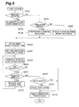
FIG. 5 is a flowchart of lower level plan generation when a lane change is planned;
FIG. 6 is a view illustrating evaluation and selection of a lower level plan of the vehicle A;
FIG. 7 is a block diagram showing a modified example of the constitution of the automatically driven vehicle A installed with the travel control plan generating system; and
FIG. 8 is a view illustrating optimum control during vehicle convergence.
BEST MODES FOR CARRYING OUT THE INVENTION
An embodiment of the present invention will be described below with reference to the attached drawings. Note that in the description of the drawings, identical elements have been allocated identical reference symbols and duplicate description thereof has been omitted.
A travel control plan generating system (also referred to simply as a “generating system” hereafter) according to this embodiment is formed using hardware of a microcomputer such as an ECU (Electronic Control Unit) and software, and is installed in an automatically driven and controlled vehicle A. As shown in FIG. 1, the generating system 1 includes a peripheral vehicle recognition unit 12, a home vehicle state quantity estimation unit 14, a peripheral vehicle behavior prediction unit (lower level plan obtaining means, inferring means) 16, a vehicle group all-vehicle behavior prediction correction unit 18, a condition setting input unit 20, a travel control plan generation unit (upper level plan generating means, lower level plan generating means) 22, an evaluation unit (evaluating means) 24, a lower level plan selection unit (lower level plan selecting means) 26, a transmission unit 28, and a reception unit (lower level plan obtaining means, communicating means) 30.
The peripheral vehicle recognition unit 12 is connected to a periphery sensor 32 that performs peripheral monitoring, such as a millimeter wave radar, an image sensor, a laser radar, or an ultrasonic wave sensor. The peripheral vehicle recognition unit 12 recognizes a peripheral vehicle C (here, a non-communicative vehicle C that is driven manually and does not have a, communication function) existing on the periphery of the vehicle A (also referred to as a home vehicle) on the basis of a detection value (reflection information from a peripheral object such as a vehicle, for example) from the periphery sensor 32, and calculates peripheral vehicle information such as a relative distance, a relative speed, and a relative angle from the home vehicle A.
The home vehicle state estimation unit 14 is connected to a home vehicle sensor 34 that detects a home vehicle's state. Examples of the home vehicle sensor 34 include a yaw rate sensor, a vehicle speed sensor an acceleration sensor, a steering angle sensor, a white line detection sensor, and a GPS. On the basis of a detection value from the home vehicle sensor 34, the home vehicle state estimation unit 14 calculates a state estimated value (a yaw rate, a lateral position within a lane, a lateral velocity, a yaw angle relative to a road shape, a home vehicle position, and so on) of the vehicle A at a corresponding point in time using a vehicle model incorporated into the software.
The peripheral vehicle behavior prediction unit 16 obtains the peripheral vehicle information calculated by the peripheral vehicle recognition unit 12 and the state estimation value of the vehicle A calculated by the home vehicle state estimation unit 14. From the obtained information, the peripheral vehicle behavior prediction unit 16 calculates a position information history of the vehicle A, a relative position information history and a relative speed of the peripheral vehicle C, and so on, and estimates the position information history and current conditions (speed, acceleration, yaw angle relative to the road alignment, and so on) of the peripheral vehicle C from this information. Thus, the positional relationships of the peripheral vehicle C and the tendencies of the peripheral vehicle C (driver preferences such as inter-vehicle distance, vehicle speed, acceleration, and willingness to change lanes) can be estimated. The peripheral vehicle behavior prediction unit 16 also obtains traveling road information (lane number increases/decreases, convergence, forks, shape, curbs, and so on) from a navigation system, infrastructure facilities, and so on. Then, on the basis of the position information history and current conditions of the peripheral vehicle C and the road information, the peripheral vehicle behavior prediction unit 16 tentatively predicts the future (for example, within approximately several hundred meters) behavior (including a travel course and a speed pattern) of the peripheral vehicle C as a lower level plan of the peripheral vehicle C from the tendencies of the peripheral vehicle C and in accordance with a driver model generated in advance.
The reception unit 30 obtains a travel control plan for another automatically driven vehicle B, which is generated by the vehicle B, through inter-vehicle communication using radio waves of 2.4 GHz or the like. The travel control plan includes a similar upper level plan, to be described below, to that of the vehicle A, and a lower level plan including a travel course and a speed pattern.
The vehicle group all-vehicle behavior prediction correction unit 18 obtains the lower level plan of the vehicle A, which is selected by the lower level plan selection unit 26, and also obtains the lower level plan of the vehicle B from the reception unit 30 and the behavior prediction (lower level plan) of the vehicle C from the peripheral vehicle behavior prediction unit 16. The vehicle group all-vehicle behavior prediction correction unit 18 then corrects the lower level plans of the respective vehicles such that mismatch points (when two vehicles overlap or the like) are eliminated by overlapping the plans on a temporal axis.
The condition setting input unit 20 receives input of overall travel conditions to a destination specified by the driver, for example the destination) desired travel time, fuel efficiency precedence, rest plans, and so on.
The travel control plan generation unit 22 includes an upper level plan generation unit (upper level plan generating means) 22 a and a lower level plan generation unit (lower level plan generating means) 22 b. The upper level plan generation unit 22 a dynamically generates a travel plan in units of several tens of km and several tens of minutes extending between interchanges IC or service areas/parking areas SAPA, taking into consideration overall travel conditions, which are set in units of several hundred km and several hours to the destination specified by the driver, travel environment conditions such as navigation information and infrastructure information, and so on. The travel plan includes the travel time, travel plan policies (rest frequency, fuel efficiency, other vehicle precedence, and so on), vehicle group organization, and so on.
More specifically, a route search to the destination is performed, and a plurality of candidate routes is selected. An optimum route satisfying traffic information, the desired travel time, and the travel plan policies is then selected. The entire route is then divided into units of ICs or SAPAs, and a travel plan is determined for each section. If necessary, a vehicle group organization policy plan is also determined as a travel plan. In a vehicle group organization policy plan, a plurality of automatically driven vehicles are organized into a vehicle group such that starts and stops can be performed en masse, thereby reducing repeated unnecessary starts and stops during travel through congestion, for example.
Further, the upper level plan generation unit 22 a dynamically generates an event transition plan in units of several hundred meters and several tens of seconds from each point in time on the basis of the travel plan generated as described above, recognition of the peripheral conditions (based on the periphery sensor 32, infrastructure monitoring information, etc.), and so on. The event transition plan includes a lane change (a completion target point, a desired lane change time (degree of urgency), a minimum allowable lane change time (during emergency avoidance or the like), whether the lane change is necessary or required for emergency avoidance, the probability of returning to the original lane, and so on), an upper limit speed modification (a new upper limit speed, a completion target point, a desired acceleration G, a desired deceleration G, a desired jerk, an allowable jerk, whether or not the required speed has been reached, and so on), an inter-vehicle distance, convergence (a desired convergence point, a desired convergence speed, a desired convergence operation time (degree of urgency), and so on), diversion (similar to convergence), organization of a rank, withdrawal from the rank, and so on. Note that the content of the parentheses indicates relevant setting conditions when an instruction is issued to the lower level plan generation unit 22 b. For example, when an instruction is issued to the vehicles as a travel plan to cooperate with their surrounding vehicles together with a congestion vehicle group control instruction, an event transition such as a lane change or an upper limit speed modification is planned in order to achieve the travel plan.
To realize the event transition plan generated by the upper level plan generation unit 22 a, the lower level plan generation unit 22 b dynamically generates a lower level plan including a target travel course and a target speed pattern in units of several centimeters and several tens of milliseconds from each point in time over several hundred meters on the basis of the road information.
Referring to FIG. 2, the lower level plan generated by the lower level plan generation unit 22 b in this manner is used to realize the upper level event transition plan generated by the upper level plan generation unit 22 a, while the event transition plan is used to realize the upper level travel plan. The travel plan corresponds to the travel policies specified by the driver. Hence, travel control plan generation is divided into multiple layers, i.e. the upper level plan and the lower level plan, and the upper level plan itself is divided into multiple layers, i.e. the travel plan and the event transition plan. As the level of the plan decreases, the time scale thereof becomes smaller than that of the upper level plan. By dividing travel control plan generation into multiple layers in this manner, a request for reconsideration of the event transition plan can be issued when a lower level plan cannot be generated by the lower level plan generation unit 22 b, and as a result, the upper level plan can be regenerated.
Note that in the travel control plan generation unit 22, the corrected lower level plans of the vehicle B and the vehicle A and the corrected behavior prediction of the vehicle C are input from the vehicle group all-vehicle behavior prediction correction unit 18, and the lower level plan is generated on the basis of this input. At this time, a travel plan and an event transition plan serving as the upper level plans of the vehicle B may be obtained by the travel control plan generation unit 22 from the vehicle group all-vehicle behavior prediction correction unit 18, and the travel plan and event transition plan of the home vehicle A may be generated on the basis of the obtained plans.
The evaluation unit 24 evaluates each of a plurality of tentatively generated lower level plans of the vehicle A on the basis of a predetermined index (for example, safety, comfort, environmental considerations (based on fuel efficiency etc.), and so on), taking into consideration the behavior prediction of the peripheral vehicle C and the lower level plan of the automatically driven vehicle B obtained from the vehicle group all-vehicle behavior prediction correction unit 18. Safety can be evaluated from the inter-vehicle distance, the steering urgency, and so on. Comfort can be evaluated from a maximum lateral G, an average lateral G, the yaw rate, and so on. As regards environmental considerations, the fuel efficiency can be evaluated from an anticipated fuel consumption and consideration to other vehicles can be evaluated from the other vehicle precedence. When the evaluation performed by the evaluation unit 24 indicates a problem such as an inability to ensure safety, the problem is corrected in the travel control plan generation unit 22, whereupon a new evaluation is performed by the evaluation unit 24. When the problem cannot be corrected, a request to reconsider the event transition plan is issued, whereby the upper level plan is regenerated.
In the evaluation performed by the evaluation unit 24, the reliability of the lower level plans is taken into account. For example, the lower level plan generated by the automatically driven vehicle B and the lower level plan inferred in relation to the manually driven vehicle C differ in terms of reliability, and therefore the lower level plans are evaluated taking the reliability thereof into account. More specifically, the reliability of the lower level plan obtained from the prediction performed by the peripheral vehicle behavior prediction unit 16 is set to be lower than the reliability of the lower level plan of the automatically driven vehicle B obtained by the reception unit 30. Hence, the inter-vehicle distance can be reduced further in relation to the automatically driven vehicle B than in relation to the manually driven vehicle C, for example.
On the basis of the evaluation results of the evaluation unit 24, the lower level plan selection unit 26 selects the lower level plan having the best evaluation from among a plurality of lower level plans as the travel control plan to be executed. For example, when safety is emphasized, the lower level plan with which the highest level of safety can be secured is selected as the travel control plan to be executed. Note that in the case described above, reliability is taken into account during the evaluation performed by the evaluation unit 24, but reliability may also be taken into account during the selection made by the lower level plan selection unit 26. In other words, an evaluation score output by the evaluation unit 24 may be multiplied by the reliability and thereby corrected, and the selection may be made on the basis of the corrected evaluation score.
On the basis of the selected lower level plan (including the travel course and speed pattern), a driving control unit 36 generates an instruction value in relation to an actuator 38, taking into account the estimated value of the home vehicle's state, such that a position and a speed at each point in time can be reproduced faithfully.
The actuator 38 is constituted by actuators of an engine, a brake, an electric power steering, and so on, and an ECU for controlling these actuators, and drive-controls these components upon reception of a throttle opening instruction value, a brake pressure instruction value, a steering torque instruction value, and so on from the driving control unit 36.
The transmission unit 28 transmits the lower level plan of the vehicle A, selected by the lower level plan selection unit 26, to the other automatically driven vehicle B through inter-vehicle communication using radio waves of 2.4 GHz or the like. At this time, the upper level plan of the vehicle A may also be transmitted.
Next, driving control of the automatically driven vehicle A installed with the travel control plan generating system 1 will be described. Here, as shown in FIG. 3, a case in which the automatically driven vehicle A is subjected to driving control in a traffic environment where the manually driven vehicle C and the automatically driven vehicle B exist as peripheral vehicles will be described.
First, the peripheral vehicle C existing on the periphery of the home vehicle A is recognized in the peripheral vehicle recognition unit 12 on the basis of a detection value from the periphery sensor 32, whereupon peripheral vehicle information such as the relative distance, angle and speed to the home vehicle A is calculated. Then, on the basis of a detection value from the home vehicle sensor 34, a state estimated value of the home vehicle A (the home vehicle position, yaw rate, lateral position within the lane, lateral velocity, yaw angle relative to road shape, and so on) at the corresponding point in time is calculated in the home vehicle state estimation unit 14.
Next, the peripheral vehicle information calculated by the peripheral vehicle recognition unit 12 and the state estimated value of the vehicle A calculated by the home vehicle state estimation unit 14 are obtained in the peripheral vehicle behavior prediction unit 16. The position information history of the vehicle A, the relative position information history and relative speed of the peripheral vehicle C, and so on are then calculated from the obtained information, and from this information, the position information history and current conditions (speed, acceleration, yaw angle relative to road shape, and so on) of the peripheral vehicle C are estimated. Thus, the positional relationships and tendencies of the peripheral vehicle C (driver preferences such as inter-vehicle distance, vehicle speed, acceleration/deceleration, and willingness to change lanes) can be estimated. The peripheral vehicle behavior prediction unit 16 also obtains traveling road information (lane number increases/decreases, convergence, forks, shape, curbs, and so on) from the navigation system, infrastructure facilities, and so on. Then, on the basis of the position information history and current conditions of the peripheral vehicle C and the road information, the peripheral vehicle behavior prediction unit 16 tentatively predicts the future (for example, within approximately several hundred meters) behavior (including the travel course and speed pattern) of the peripheral vehicle C from the tendencies of the peripheral vehicle C and in accordance with a driver model generated in advance. At this time, the behavior prediction of the peripheral vehicle C is generated together with a reliability value. The reliability value is set at a predetermined value, which is lower than the reliability of the lower level plan of the automatically driven vehicle B.
Next, the vehicle group all-vehicle behavior prediction correction unit 18 obtains the lower level plan of the vehicle A selected by the lower level plan selection unit 26, and also obtains the lower level plan of the vehicle B from the reception unit 30 and the behavior prediction of the vehicle C from the peripheral vehicle behavior prediction unit 16. The vehicle group all-vehicle behavior prediction correction unit 18 then corrects the lower level plans of the respective vehicles such that mismatch points (when two vehicles overlap or the like) are eliminated by overlapping the plans on a temporal axis.
Thus, the lower level plans of the vehicles B and C serving as peripheral vehicles can be obtained, as shown in FIG. 4. Here, C′, C″ denote the position of the vehicle C at intervals of several tens of milliseconds, for example (likewise in relation to the vehicle B).
Meanwhile, the condition setting input unit 20 receives input of the overall travel conditions to the destination specified by the driver, for example the destination, desired travel time, fuel efficiency precedence, rest plans, and so on.
Next, the upper level plan generation unit 22 a dynamically generates a travel plan in units of several tens of km and several tens of minutes extending between interchanges IC or service areas/parking areas SAPA, taking into consideration the overall travel conditions, which are set in units of several hundred km and several hours to the destination specified by the driver, travel environment conditions such as the navigation information and infrastructure information, and so on.
More specifically, a route search to the destination is performed, and a plurality of candidate routes is selected. An optimum route satisfying the traffic information, the desired travel time, and the travel plan policies is then selected. The entire route is then divided into units of ICs or SAPAs, and a travel plan is determined for each section. If necessary, a vehicle group organization policy plan is also determined as a travel plan.
Further, the upper level plan generation unit 22 a dynamically generates an event transition plan in units of several hundred meters and several tens of seconds from each point in time on the basis of the travel plan generated as described above, recognition of the peripheral conditions, and so on.
Next, in order to realize the event transition plan generated by the upper level plan generation unit 22 a, the lower level plan generation unit 22 b dynamically generates a lower level plan including a target travel course and a target speed pattern in units of several centimeters and several tens of milliseconds from each point in time over several hundred meters on the basis of the road information. At this time, a plurality of lower level plans may be generated using an identical course generation method, or the plurality of lower level plans may be generated using various course generation methods. Furthermore, when the corresponding event transition is not necessary, a plurality of lower level plans may be generated for each of a case in which the event is performed and a case in which the event is not performed.
When the lower level plan cannot be generated by the lower level plan generation unit 22 b, a request for reconsideration of the event transition plan is issued, and as a result, the upper level plan is regenerated. A lower level plan for realizing the new upper level plan is then generated.
More specifically, as shown in FIG. 5, when a lane change is planned as the upper level plan, for example, first, a determination is made in the lower level plan generation unit 22 b as to whether or not emergency avoidance is required (step S401). When emergency avoidance is required, emergency avoidance setting, such as permitting sudden steering, is performed, whereupon the procedure advances to a step S403. When emergency avoidance is not required, on the other hand, a determination is made as to whether or not the number of lanes is about to decrease (step S404). When the number of lanes is about to decrease, setting indicating that the original lane cannot be returned to through normal steering is performed (step S405), whereupon the procedure advances to the step S403. When the number of lanes is not about to decrease, on the other hand, setting indicating that the original lane can be returned to through first-half gentle steering is performed (step S406), whereupon the procedure advances to the step S403.
In the step S403, a completion target point of the lane change is set, and in a following step S407, a time required to perform the lane change is set. On the basis of the set information, a lane change course is then tentatively generated (step S408). Next, a determination is made as to whether or not sufficient time is available to perform the lane change (step S409). When sufficient time is available, the procedure advances to a step S410. When sufficient time is not available, on the other hand, a determination is made as to whether or not the available time is a minimum allowable time (step S411). When the available time is not the minimum allowable time and some leeway exists, the time required to perform the lane change is shortened (step S412), whereupon the procedure returns to the step S408. When the available time is the minimum allowable time, on the other hand, a determination is made in a step S413 as to whether or not the lane change is necessary, and when the lane change is necessary, the procedure advances to the step S410. When the lane change is not necessary, a determination is made in a step S414 to cancel the lane change, whereupon the procedure advances to the step S410. In the step S410, the determined content is transmitted to an upper order layer. Accordingly, a determination to perform the lane change along the course generated when the available time is sufficient, a determination to perform the lane change along the course generated when the available time is insufficient but corresponds to the minimum allowable time and the lane change is necessary, or a determination to cancel the lane change when the available time is insufficient and corresponds to the minimum allowable time and the lane change is not necessary, is transmitted to the upper order layer When the lane change is canceled, a new event transition plan not including a lane change is generated, and a lower level plan for realizing the new event transition plan is generated.
Next, the evaluation unit 24 evaluates each of the plurality of tentatively generated lower level plans of the vehicle A on the basis of the predetermined index (for example, safety, comfort, environmental considerations (based on fuel efficiency etc.), and so on), taking into consideration the behavior prediction of the peripheral vehicle C and the lower level plan of the automatically driven vehicle B obtained from the vehicle group all-vehicle behavior prediction correction unit 18. When the evaluation performed by the evaluation unit 24 indicates a problem such as an inability to ensure safety, the problem is corrected in the travel control plan generation unit 22, whereupon a new evaluation is performed by the evaluation unit 24. When the problem cannot be corrected, a request to reconsider the event transition plan is issued, whereby the upper level plan is regenerated.
In the evaluation performed by the evaluation unit 24, the reliability of the lower level plans is taken into account. For example, the lower level plan generated by the automatically driven vehicle B and the lower level plan inferred in relation to the manually driven vehicle C differ in reliability, and therefore the lower level plans are evaluated taking the reliability thereof into account. More specifically, the reliability of the lower level plan obtained from the prediction performed by the peripheral vehicle behavior prediction unit 16 is set to be lower than the reliability of the lower level plan of the automatically driven vehicle B obtained by the reception unit 30. Thus, the inter-vehicle distance can be reduced further in relation to the automatically driven vehicle B than in relation to the manually driven vehicle C, for example.
On the basis of the evaluation results of the evaluation unit 24, the lower level plan selection unit 26 selects the lower level plan having the best evaluation from among the plurality of lower level plans as the travel control plan to be executed. For example, when safety is emphasized, the lower level plan with which the highest level of safety can be secured is selected as the travel control plan to be executed.
FIG. 6 is a view illustrating evaluation and selection of the lower level plan of the vehicle A. As shown in FIG. 6, it is assumed that a lane change is planned as the upper level plan, and that a route I and a route II have been generated as the lower level plans. At this time, the 25 reliability of the lower level plan of the automatically driven vehicle B is higher than the reliability of the lower level plan of the manually driven vehicle C, and therefore the route II is evaluated as having a higher level of safety. Hence, when safety is to be emphasized, the lower level plan selection unit 26 selects the route II having the higher level of safety as the lower level plan of the vehicle A.
Next, on the basis of the selected lower level plan (including the travel course and speed pattern), the driving control unit 36 generates an instruction value in relation to the actuator 38, taking into account the estimated value of the home vehicle state of quantity, such that the position and speed at each point in time can be reproduced faithfully.
The actuator 38 then drive-controls the engine, the brake, the steering, and so on upon reception of a throttle opening instruction value, a brake pressure instruction value, a steering torque instruction value, and so on from the driving control unit 36, whereby the vehicle A is subjected to automatic driving control.
Meanwhile, the transmission unit 28 transmits the lower level plan of the vehicle A, selected by the lower level plan selection unit 26, to the other automatically driven vehicle B. At this time, the upper level plan of the vehicle A may also be transmitted.
Hence, in the travel control plan generating system 1 according to this embodiment, an upper level plan corresponding to the travel policy of the vehicle A can be generated, and a lower level plan for realizing the upper level plan can be generated. As the level of the plan decreases, the time scale thereof becomes smaller than that of the upper level plan. The lower level plan includes at least a travel course, and the lower level plan of the vehicle A is evaluated in consideration of the lower level plans of the peripheral vehicles B, C. A lower level plan to be executed can then be selected in accordance with the evaluation. By stratifying the travel control plan into an upper level plan and a lower level plan in this manner, variation in the conditions of the peripheral environment can be responded to flexibly by means of the lower level plan while satisfying the travel policy by means of the upper level plan. Furthermore, the lower level plan can be selected on the basis of an evaluation performed in accordance with a predetermined index (for example, safety, comfort, environmental considerations (based on fuel efficiency etc.), and so on), and therefore the vehicle A can be controlled on the basis of an appropriate plan corresponding to conditions specified by the driver. In other words, by evaluating and selecting lower level plans that have been broken down into a smaller time scale than the upper level plan, realization of the upper level plan and a flexible response to the peripheral environment can both be realized favorably.
In other words, in the vehicle control according to this embodiment, in contrast to IMTS (Intelligent Multimode Transit System, reserved road travel), a single plan is not shared by a plurality of vehicles. On a reserved road, the travel road is fixed, and therefore an optimum plan can be generated by adjusting all of the plans in advance. On a normal road, however, the travel road is used for a wide range of purposes, peripheral vehicles are unknown, and each vehicle travels in accordance with its own plan. Therefore, a plan that takes into consideration the plans of the peripheral vehicles must be devised to ensure that the vehicles operate harmoniously, and since it is substantially impossible to travel in accordance with a preset optimum plan, the plan must be adjusted dynamically in accordance with the peripheral vehicles. In this embodiment, travel control plan generation is performed in a multi-layer fashion, and therefore a lower level plan can be generated flexibly in accordance with the peripheral vehicles while realizing the absolute upper level plan. Hence, optimum vehicle control can be performed.
Further, a plurality of lower level plans is generated in relation to the vehicle A, and on the basis of the evaluation performed by the evaluation unit 24, a lower level plan to be executed is selected from the plurality of lower level plans. Therefore, the vehicle A can be controlled on the basis of an appropriate plan corresponding to the conditions specified by the driver.
Further, when a lower level plan cannot be generated, the upper level plan is regenerated, or the upper level plan is regenerated in accordance with the evaluation performed by the evaluation unit 24, and therefore the upper level plan can be reconsidered when a lower level plan cannot be generated or the predetermined index specified by the driver cannot be satisfied sufficiently.
Further, the peripheral vehicle behavior prediction unit 16 infers the lower level plan of the peripheral vehicle on the basis of the behavior of the peripheral vehicle, and therefore, a lower level plan can be obtained in relation to a peripheral vehicle that does not include communication means or the peripheral vehicle (for example, a manually driven vehicle) C that does not have a travel control plan. Furthermore, the lower level plan of the peripheral vehicle can be obtained by the reception unit 30, and therefore the lower level plan of the automatically driven vehicle B, which is a peripheral vehicle having a travel control plan, and the lower level plan of a peripheral vehicle of the automatically driven vehicle B, which is inferred in the automatically driven vehicle B, can be obtained through communication. Hence, in a traffic environment where manually driven vehicles and automatically driven vehicles coexist, the vehicle A can be subjected to travel control on the basis of a more appropriate plan.
Further, the evaluation unit 24 evaluates the lower level plan of the vehicle A taking into consideration the reliability of the lower level plans of the peripheral vehicles. Here, a lower level plan is generated by the automatically driven vehicle B and inferred in relation to the manually driven vehicle C, and therefore the reliability levels of the respective lower level plans of the peripheral vehicles are different. Therefore, by taking the reliability into account while evaluating the lower level plan of the vehicle A, the vehicle A can be subjected to travel control on the basis of a more appropriate plan.
Further, the reliability of the lower level plan obtained from the prediction made by the peripheral vehicle behavior prediction unit 16 is lower than the reliability of the lower level plan of the automatically driven vehicle B obtained by the communication unit 30, and therefore, by performing the evaluation on the basis of the reliability, the vehicle A can be subjected to travel control on the basis of a more appropriate plan in a traffic environment where the manually driven vehicle C and the automatically driven vehicle B coexist.
Furthermore, the lower level plan includes a speed pattern in addition to the travel course of the vehicle A, and therefore longitudinal direction control corresponding to the speed pattern can be set as a control target in addition to lateral direction control corresponding to the travel course.
Note that the present invention is not limited to the embodiment described above, and may be subjected to various modifications, For example, in the embodiment described above, a traffic environment in which the automatically driven vehicle B and the manually driven non-communicative vehicle C coexist as the peripheral vehicles of the automatically driven vehicle A was described, but other automatically driven vehicles and manually driven non-communicative vehicles may also exist.
Further, as shown in FIG. 7, a vehicle D that is manually driven but capable of communication may exist as a peripheral vehicle. As shown in FIG. 7, the vehicle D includes a driving support control apparatus 100. The driving support control apparatus 100 includes a behavior prediction unit 116, a behavior suggestion unit 118, a display unit 120, an ACC/LKA correction unit 122, a reception unit 130, and a transmission unit 132.
The reception unit 130 receives the lower level plans of the vehicles A, B and the behavior prediction for the vehicle C, which is predicted in the vehicle A. The behavior prediction unit 116 predicts the behavior of the vehicle D from vehicle-installed sensor information relating to a vehicle speed sensor, an accelerator pedal sensor, a brake sensor, a steering angle sensor, and so on of the vehicle D, the behavior prediction result generated by the vehicle A in relation to the vehicle C, which is obtained via the reception unit 130, and the lower level plans of the vehicles A, B. At this time, the reliability of the behavior prediction (lower level plan) of the vehicle D is set for use during lower level plan generation in the travel control plan generation unit 22 of the vehicle A. The reliability of the manually driven communicative vehicle D is set to be higher than the reliability of the manually driven non-communicative vehicle C and lower than the reliability of the automatically driven vehicle B.
The transmission unit 132 transmits the behavior prediction (lower level plan) of the vehicle D to the vehicle A. When the display unit 120 or a driving support apparatus such as an ACC (adaptive cruise control) apparatus or an LKA (lane keep assist) apparatus exists in the non-automatically driven vehicle D, the behavior suggestion unit 118 generates a preferable behavior for the driver or the driving support apparatus. The display unit 120 displays the preferable driving method as a suggestion to the driver performing manual driving. The ACC/LKA correction unit 122 generates a target speed correction and a steering assist torque corresponding to the ACC/LKA driving support apparatus or the like in accordance with the preferred driving method.
Hence, when the communicative manually driven vehicle D exists, the behavior of the peripheral vehicle D, which may affect the home vehicle A, can be predicted with a high degree of precision through cooperation with the peripheral vehicle D, and therefore an appropriate travel control plan can be generated for the automatically driven vehicle A in a traffic environment where automatically driven vehicles and manually driven vehicles coexist. Moreover, suggestions for preferred driving directions and driving support can be issued to the vehicle D.
Further, a traffic environment in which the automatically driven vehicle B and the manually driven non-communicative vehicle C coexist as the peripheral vehicles of the automatically driven vehicle A and a traffic environment in which the manually driven communicative vehicle D exists were described in the above embodiment, but an optimum lower level plan can also be generated for all vehicles in a case where convergence is considered within an environment where a plurality of automatically driven vehicles α, β, γ coexist, as shown in FIG. 8. More specifically, as shown in FIG. 8( a), when a lower level plan according to which a vehicle α performs a lane change while a vehicle β travels at a constant speed is generated, the lower level plan is shared among the vehicles α, β, γ such that first, a safest lower level plan is generated for a convergence vehicle γ in relation to the main road vehicles α, β, as shown in FIG. 8( b), and on the basis thereof, the vehicle β is decelerated, the lane change to be performed by the vehicle α is canceled, and so on, as shown in FIG. 8( c). Thus, optimum overall vehicle control can be performed. In this case, the behavior of a manually driven vehicle can be predicted when such a vehicle is present, and therefore optimum vehicle control can still be performed.
Furthermore, in the above embodiment, a case in which the travel control plan generating system 1 is installed in the automatically driven vehicle A was described, but the system 1 may be provided on the infrastructure facility side.
Industrial Applicability
According to the present invention, a travel control plan generating system and a computer program capable of responding flexibly to variation in the conditions of a peripheral environment while satisfying a travel policy of a home vehicle can be provided.

Claims (10)

The invention claimed is:
1. A travel control plan generating system for an automatically driven vehicle, comprising:
an upper level plan generating unit configured to generate an upper level plan corresponding to a travel policy of the vehicle, said upper level plan being generated for each divided section to the destination in units of a first distance and a first time scale;
a lower level plan generating unit configured to generate a lower level plan including at least a travel course, said lower level plan being generated in units of a second distance and a second time scale and configured to achieve said upper level plan of said each divided section, the second distance and the second time scale being smaller than the first distance and the first time scale, respectively;
a lower level plan obtaining unit configured to obtain a lower level plan including at least a travel course of a peripheral vehicle of said vehicle;
an evaluating unit configured to evaluate said lower level plan of said vehicle in accordance with a predetermined index, taking into account said lower level plan of said peripheral vehicle; and
a lower level plan selecting unit configured to select a lower level plan to be executed by said vehicle on the basis of an evaluation performed by said evaluating unit,
wherein said lower level plan obtaining unit includes an inferring unit configured to infer said lower level plan of said peripheral vehicle on the basis of a behavior of said peripheral vehicle, said lower level plan of said peripheral vehicle is obtained from an inference by said inferring unit,
said lower level plan obtaining unit further includes a communicating unit configured to communicate with said peripheral vehicle, said lower level plan including at least a travel course of said peripheral vehicle generated at said peripheral vehicle is obtained through communication performed by said communicating unit,
said evaluating unit is configured to evaluate said lower level plan of said vehicle taking into account a reliability of said lower level plan of said peripheral vehicle, and
a reliability of a lower level plan of said peripheral vehicle obtained from said inferring unit is set to be lower than a reliability of a lower level plan of an automatically driven peripheral vehicle obtained from said communicating unit.
2. The travel control plan generating system according to claim 1, wherein said lower level plan generating unit is configured to generate a plurality of lower level plans for said vehicle, and
said lower level plan selecting unit is configured to select said lower level plan to be executed from said plurality of lower level plans on the basis of said evaluation performed by said evaluating unit.
3. The travel control plan generating system according to claim 1, wherein said upper level plan generating unit is configured to regenerate said upper level plan when said lower level plan cannot be generated.
4. The travel control plan generating system according to claim 1, wherein said upper level plan generating unit is configured to regenerate said upper level plan in accordance with said evaluation performed by said evaluating unit.
5. The travel control plan generating system according to claim 1, wherein said lower level plan includes a speed pattern of said vehicle.
6. The travel control plan generating system according to claim 1, wherein:
the units of a first distance and a first time scale are several hundred meters and several tens of seconds, respectively; and
the units of a second distance and a second time scale are several centimeters and several tens of milliseconds, respectively.
7. The travel control plan generating system according to claim 1, wherein:
the reliability of the lower level plan obtained from said inferring unit and the reliability of the lower level plan from said communicating unit are respectively set based on a quality of the lower level plan obtained from said inferring unit and a quality of the lower level plan obtained from said communicating unit.
8. A non-transitory computer readable storage medium storing a program for causing a computer to execute a process, the process comprising:
generating an upper level plan corresponding to a travel policy of an automatically driven vehicle, said upper level plan being generated for each divided section to the destination in units of a first distance and a first time scale;
generating a lower level plan including at least a travel course, said lower level plan being generated in units of a second distance and a second time scale and configured to achieve said upper level plan of said each divided section, the second distance and the second time scale being smaller than the first distance and the first time scale, respectively;
obtaining a lower level plan including at least a travel course of a peripheral vehicle of said vehicle;
evaluating said lower level plan of said vehicle in accordance with a predetermined index, taking into account said lower level plan of said peripheral vehicle; and
selecting a lower level plan to be executed by said vehicle on the basis of an evaluation performed in said evaluating step,
wherein said obtaining a lower level plan includes inferring said lower level plan of said peripheral vehicle on the basis of a behavior of said peripheral vehicle, said lower level plan of said peripheral vehicle is obtained from an inference by said inferring,
said obtaining a lower level plan further includes communicating with said peripheral vehicle, said lower level plan including at least a travel course of said peripheral vehicle generated at said peripheral vehicle is obtained through communication performed by said communicating,
said evaluating evaluates said lower level plan of said vehicle taking into account a reliability of said lower level plan of said peripheral vehicle, and
a reliability of a lower level plan obtained from said inferring is set to be lower than a reliability of a lower level plan of an automatically driven vehicle obtained from said communicating.
9. The non-transitory computer readable storage medium according to claim 8, wherein:
the reliability of the lower level plan obtained from said inferring unit and the reliability of the lower level plan from said communicating unit are respectively set based on a quality of the lower level plan obtained from said inferring unit and a quality of the lower level plan obtained from said communicating unit.
10. A travel control plan generating system for an automatically driven vehicle, comprising:
a travel plan generating unit configured to generate a travel plan including at least a travel course;
a travel plan obtaining unit configured to obtain a travel plan including at least a travel course of a peripheral vehicle of said vehicle;
an evaluating unit configured to evaluate said travel plan of said vehicle in accordance with a predetermined index, taking into account said travel plan of said peripheral vehicle; and
a travel plan selecting unit configured to select a travel plan to be executed by said vehicle on the basis of an evaluation performed by said evaluating unit,
wherein said travel plan obtaining unit includes an inferring unit configured to infer said travel plan of said peripheral vehicle on the basis of a behavior of said peripheral vehicle, said travel plan of said peripheral vehicle is obtained from an inference by said inferring unit,
said travel plan obtaining unit further includes a communicating unit configured to communicate with said peripheral vehicle, said travel plan including at least a travel course of said peripheral vehicle generated at said peripheral vehicle is obtained through communication performed by said communicating unit,
said evaluating unit is configured to evaluate said travel plan of said vehicle taking into account a reliability of said travel plan of said peripheral vehicle, and
a reliability of a travel plan of said peripheral vehicle obtained from said inferring is set to be lower than a reliability of a travel plan of a peripheral vehicle obtained from said communicating unit.
US12/515,391 2006-11-20 2007-11-20 Travel control plan generation system and computer program Active 2031-10-15 US9076338B2 (en)

Applications Claiming Priority (3)

Application Number Priority Date Filing Date Title
JP2006313258A JP4525670B2 (en) 2006-11-20 2006-11-20 Travel control plan generation system
JP2006-313258 2006-11-20
PCT/JP2007/072885 WO2008062897A1 (en) 2006-11-20 2007-11-20 Travel control plan generation system and computer program

Publications (2)

Publication Number Publication Date
US20100042282A1 US20100042282A1 (en) 2010-02-18
US9076338B2 true US9076338B2 (en) 2015-07-07

Family

ID=39429824

Family Applications (1)

Application Number Title Priority Date Filing Date
US12/515,391 Active 2031-10-15 US9076338B2 (en) 2006-11-20 2007-11-20 Travel control plan generation system and computer program

Country Status (5)

Country Link
US (1) US9076338B2 (en)
EP (1) EP2096612B1 (en)
JP (1) JP4525670B2 (en)
CN (1) CN101542553B (en)
WO (1) WO2008062897A1 (en)

Cited By (5)

* Cited by examiner, † Cited by third party
Publication number Priority date Publication date Assignee Title
US9953472B2 (en) * 2016-05-04 2018-04-24 General Electric Company System and method for determining grade errors of a route
US20180273032A1 (en) * 2015-11-30 2018-09-27 Huawei Technologies Co., Ltd. Automatic Driving Navigation Method, Apparatus, and System, In-Vehicle Terminal, and Server
US20190001986A1 (en) * 2015-07-13 2019-01-03 Hitachi Automotive Systems, Ltd. Surrounding environment recognition device and computer program product
US10647354B2 (en) * 2017-06-06 2020-05-12 Toyota Jidosha Kabushiki Kaisha Steering assist device
US11180150B2 (en) 2016-04-11 2021-11-23 Volkswagen Ag Method for the autonomous or partly autonomous execution of a cooperative driving maneuver

Families Citing this family (118)

* Cited by examiner, † Cited by third party
Publication number Priority date Publication date Assignee Title
CN101393686B (en) * 2008-10-13 2011-07-20 徐菲 All-weather vehicle driving safety indication and control system device
EP2383710B1 (en) * 2009-01-28 2013-12-11 Toyota Jidosha Kabushiki Kaisha Vehicle group control method and vehicle group control device
JP5316186B2 (en) * 2009-04-10 2013-10-16 トヨタ自動車株式会社 Vehicle control apparatus and vehicle control method
WO2011048688A1 (en) * 2009-10-22 2011-04-28 トヨタ自動車株式会社 Travel controller
KR101291067B1 (en) * 2009-11-26 2013-08-07 한국전자통신연구원 Car control apparatus and its autonomous driving method, local sever apparatus and its autonomous driving service method, whole region sever apparatus and its autonomous driving service method
WO2011074096A1 (en) * 2009-12-17 2011-06-23 トヨタ自動車株式会社 Vehicle control device
DE112009005449B4 (en) 2009-12-18 2022-02-24 Toyota Jidosha Kabushiki Kaisha RIDE CONTROL DEVICE
JP5273259B2 (en) 2009-12-22 2013-08-28 トヨタ自動車株式会社 Vehicle control device
CN102712318B (en) * 2010-01-15 2015-04-08 丰田自动车株式会社 Vehicle control device
JP5413466B2 (en) 2010-01-15 2014-02-12 トヨタ自動車株式会社 Vehicle control device
JP5552339B2 (en) * 2010-03-12 2014-07-16 トヨタ自動車株式会社 Vehicle control device
JP5663942B2 (en) * 2010-05-11 2015-02-04 トヨタ自動車株式会社 Traveling track creation device
US8897948B2 (en) * 2010-09-27 2014-11-25 Toyota Systems and methods for estimating local traffic flow
US8509982B2 (en) 2010-10-05 2013-08-13 Google Inc. Zone driving
JP2012081897A (en) * 2010-10-13 2012-04-26 Toyota Motor Corp Drive assist system
KR101074638B1 (en) * 2011-05-04 2011-10-18 한국항공우주연구원 Lane determination method using steering wheel model
US8855847B2 (en) 2012-01-20 2014-10-07 Toyota Motor Engineering & Manufacturing North America, Inc. Intelligent navigation system
DE102012201982A1 (en) * 2012-02-10 2013-08-14 Robert Bosch Gmbh Method and device for community-based navigation
JP5921246B2 (en) * 2012-02-15 2016-05-24 三菱電機株式会社 Information equipment
JP5916444B2 (en) * 2012-03-08 2016-05-11 日立建機株式会社 Mining vehicle
US8457827B1 (en) * 2012-03-15 2013-06-04 Google Inc. Modifying behavior of autonomous vehicle based on predicted behavior of other vehicles
US8793046B2 (en) 2012-06-01 2014-07-29 Google Inc. Inferring state of traffic signal and other aspects of a vehicle's environment based on surrogate data
KR101394884B1 (en) 2012-06-18 2014-05-13 현대모비스 주식회사 Congestion Control Device and Method for Inter-Vehicle Communication
JP6003349B2 (en) * 2012-07-27 2016-10-05 トヨタ自動車株式会社 Vehicle behavior prediction device
US9026300B2 (en) * 2012-11-06 2015-05-05 Google Inc. Methods and systems to aid autonomous vehicles driving through a lane merge
US9446766B2 (en) 2013-02-01 2016-09-20 Hitachi Automotive Systems, Ltd. Travel control device and travel control system
GB201305067D0 (en) * 2013-03-19 2013-05-01 Massive Analytic Ltd Apparatus for controlling a land vehicle which is self-driving or partially self-driving
US9074894B2 (en) * 2013-07-08 2015-07-07 GM Global Technology Operations LLC Vehicle range projection estimation
JP6155973B2 (en) * 2013-08-27 2017-07-05 株式会社デンソー Driving support device and driving support method
TWI511069B (en) * 2013-11-28 2015-12-01 Inst Information Industry Travel plan apparatus, method and storage media
JP6269104B2 (en) * 2014-01-27 2018-01-31 アイシン・エィ・ダブリュ株式会社 Automatic driving support system, automatic driving support method, and computer program
JP6308032B2 (en) * 2014-06-04 2018-04-11 株式会社デンソー System and method for generating driving maneuvers
US20170043784A1 (en) * 2014-06-06 2017-02-16 Hitachi Automotive Systems, Ltd. Vehicle Travel Control Device
JP6245083B2 (en) * 2014-06-06 2017-12-13 株式会社デンソー Control device
US9321461B1 (en) 2014-08-29 2016-04-26 Google Inc. Change detection using curve alignment
JP6353322B2 (en) * 2014-09-04 2018-07-04 日立建機株式会社 Transport vehicle and travel control device thereof
US9248834B1 (en) 2014-10-02 2016-02-02 Google Inc. Predicting trajectories of objects based on contextual information
JP6430799B2 (en) * 2014-11-28 2018-11-28 株式会社デンソー Vehicle travel control device
WO2016113893A1 (en) * 2015-01-16 2016-07-21 三菱重工メカトロシステムズ株式会社 Navigation system and on-board unit
JP6365402B2 (en) * 2015-05-13 2018-08-01 トヨタ自動車株式会社 Travel control device
JP6394497B2 (en) * 2015-05-25 2018-09-26 トヨタ自動車株式会社 Automatic vehicle driving system
KR20180008726A (en) * 2015-06-03 2018-01-24 닛산 지도우샤 가부시키가이샤 Vehicle control device and vehicle control method
JP6448154B2 (en) * 2015-07-10 2019-01-09 本田技研工業株式会社 Vehicle control device, vehicle control method, and vehicle control program
BR112018001165B1 (en) * 2015-07-21 2023-11-07 Nissan Motor Co., Ltd DRIVING PLANNING DEVICE, TRAVEL AID DEVICE AND DRIVING PLANNING METHOD
JP6421716B2 (en) * 2015-07-29 2018-11-14 トヨタ自動車株式会社 Vehicle driving support control device
DE112016003572T5 (en) 2015-08-06 2018-05-17 Honda Motor Co., Ltd. VEHICLE CONTROL DEVICE, VEHICLE CONTROL PROCEDURE AND VEHICLE CONTROL PROGRAM
EP3335954A4 (en) * 2015-08-17 2018-09-12 Yamaha Hatsudoki Kabushiki Kaisha Leaning vehicle
CN108137058B (en) * 2015-09-30 2019-04-16 日产自动车株式会社 Information presentation device and information cuing method
CN106652515B (en) * 2015-11-03 2020-03-20 中国电信股份有限公司 Automatic vehicle control method, device and system
US9910441B2 (en) * 2015-11-04 2018-03-06 Zoox, Inc. Adaptive autonomous vehicle planner logic
JP6162892B2 (en) * 2015-11-30 2017-07-12 株式会社小松製作所 Work machine control system, work machine, work machine management system, and work machine control method
JP6558239B2 (en) * 2015-12-22 2019-08-14 アイシン・エィ・ダブリュ株式会社 Automatic driving support system, automatic driving support method, and computer program
DE102015016758A1 (en) * 2015-12-23 2017-06-29 Daimler Ag Method for moving, in particular for controlling or regulating, a vehicle convoy
JP6512140B2 (en) 2016-03-09 2019-05-15 トヨタ自動車株式会社 Automatic driving system
JP6270227B2 (en) * 2016-03-14 2018-01-31 本田技研工業株式会社 Vehicle control device, vehicle control method, and vehicle control program
JP6617628B2 (en) * 2016-03-18 2019-12-11 スズキ株式会社 Inter-vehicle information sharing system
US9645577B1 (en) * 2016-03-23 2017-05-09 nuTonomy Inc. Facilitating vehicle driving and self-driving
MX2018011511A (en) * 2016-03-24 2019-01-10 Nissan Motor Course estimation method and course estimation device.
US10902725B2 (en) 2016-03-25 2021-01-26 Hitachi Automotive Systems, Ltd. Vehicle control device
WO2017168662A1 (en) * 2016-03-30 2017-10-05 三菱電機株式会社 Travel plan generation device, travel plan generation method, and travel plan generation program
US11169537B2 (en) 2016-04-15 2021-11-09 Honda Motor Co., Ltd. Providing driving support in response to changes in driving environment
JP2017213936A (en) * 2016-05-30 2017-12-07 本田技研工業株式会社 Vehicle control system, vehicle control method, and vehicle control program
CN109641593B (en) * 2016-09-07 2021-07-27 三菱电机株式会社 Travel plan correction device and travel plan correction method
US11142197B2 (en) 2016-10-18 2021-10-12 Honda Motor Co., Ltd. Vehicle control device
CN109843681B (en) * 2016-10-18 2022-04-01 本田技研工业株式会社 Vehicle control device
CN109963760B (en) * 2016-10-18 2022-04-01 本田技研工业株式会社 Vehicle control device
JP6637193B2 (en) * 2016-10-18 2020-01-29 本田技研工業株式会社 Vehicle control device
JP6713410B2 (en) * 2016-11-21 2020-06-24 日立オートモティブシステムズ株式会社 Electronic control unit
US20200388163A1 (en) * 2016-11-28 2020-12-10 Telefonaktiebolaget Lm Ericsson (Publ) Prediction based client control
KR102471072B1 (en) * 2016-12-21 2022-11-25 삼성전자주식회사 Electronic apparatus and operating method for the same
US10133275B1 (en) * 2017-03-01 2018-11-20 Zoox, Inc. Trajectory generation using temporal logic and tree search
WO2018162521A1 (en) 2017-03-07 2018-09-13 Robert Bosch Gmbh Action planning system and method for autonomous vehicles
US11150662B2 (en) 2017-03-30 2021-10-19 Nec Corporation Vehicle control system, self-driving vehicle, vehicle control method, and program
JP6781335B2 (en) * 2017-03-30 2020-11-04 本田技研工業株式会社 Vehicle control system, server device, vehicle control method, and vehicle control program
JP6624150B2 (en) 2017-04-11 2019-12-25 トヨタ自動車株式会社 Autonomous driving system
US10814913B2 (en) 2017-04-12 2020-10-27 Toyota Jidosha Kabushiki Kaisha Lane change assist apparatus for vehicle
BR112019024714A2 (en) * 2017-05-24 2020-06-09 Nissan Motor travel assistance method of travel assistance device and travel assistance device
JP6627822B2 (en) * 2017-06-06 2020-01-08 トヨタ自動車株式会社 Lane change support device
JP6627821B2 (en) * 2017-06-06 2020-01-08 トヨタ自動車株式会社 Lane change support device
JP6642522B2 (en) * 2017-06-06 2020-02-05 トヨタ自動車株式会社 Lane change support device
JP6897349B2 (en) * 2017-06-09 2021-06-30 トヨタ自動車株式会社 Driving support device
WO2019000391A1 (en) * 2017-06-30 2019-01-03 华为技术有限公司 Vehicle control method, device, and apparatus
US10545505B2 (en) * 2017-08-28 2020-01-28 Toyota Research Institute, Inc Trajectory plan modification for an autonomous vehicle operation in a heterogeneous vehicle environment
JP7027738B2 (en) 2017-09-06 2022-03-02 株式会社デンソー Driving support device
JP6917253B2 (en) * 2017-09-15 2021-08-11 本田技研工業株式会社 Vehicle control device, vehicle, vehicle control device processing method and program
JP6933080B2 (en) * 2017-10-05 2021-09-08 いすゞ自動車株式会社 Vehicle speed control device
JP7020130B2 (en) * 2018-01-17 2022-02-16 トヨタ自動車株式会社 Vehicle controls, methods, and programs
JP7003689B2 (en) * 2018-01-29 2022-01-20 トヨタ自動車株式会社 Control device and agent cooperation method
US10955851B2 (en) 2018-02-14 2021-03-23 Zoox, Inc. Detecting blocking objects
CN108609016A (en) * 2018-03-12 2018-10-02 上海伊控动力系统有限公司 A kind of Vehicular intelligent speed limiting system and method based on vehicle net
US11334067B2 (en) 2018-04-11 2022-05-17 Hyundai Motor Company Apparatus and method for providing safety strategy in vehicle
US11084490B2 (en) 2018-04-11 2021-08-10 Hyundai Motor Company Apparatus and method for controlling drive of vehicle
US10843710B2 (en) 2018-04-11 2020-11-24 Hyundai Motor Company Apparatus and method for providing notification of control authority transition in vehicle
US11548509B2 (en) * 2018-04-11 2023-01-10 Hyundai Motor Company Apparatus and method for controlling lane change in vehicle
US10836394B2 (en) 2018-04-11 2020-11-17 Hyundai Motor Company Apparatus and method for lane change control
US11351989B2 (en) 2018-04-11 2022-06-07 Hyundai Motor Company Vehicle driving controller, system including the same, and method thereof
US11173910B2 (en) 2018-04-11 2021-11-16 Hyundai Motor Company Lane change controller for vehicle system including the same, and method thereof
US11597403B2 (en) 2018-04-11 2023-03-07 Hyundai Motor Company Apparatus for displaying driving state of vehicle, system including the same and method thereof
US11084491B2 (en) 2018-04-11 2021-08-10 Hyundai Motor Company Apparatus and method for providing safety strategy in vehicle
US11077854B2 (en) * 2018-04-11 2021-08-03 Hyundai Motor Company Apparatus for controlling lane change of vehicle, system having the same and method thereof
EP3552902A1 (en) 2018-04-11 2019-10-16 Hyundai Motor Company Apparatus and method for providing a driving path to a vehicle
EP3569460B1 (en) 2018-04-11 2024-03-20 Hyundai Motor Company Apparatus and method for controlling driving in vehicle
ES2889930T3 (en) 2018-04-11 2022-01-14 Hyundai Motor Co Ltd Apparatus and method for control to enable an autonomous system in a vehicle
EP3552901A3 (en) 2018-04-11 2020-04-29 Hyundai Motor Company Apparatus and method for providing safety strategy in vehicle
DE102018109883A1 (en) * 2018-04-24 2018-12-20 Continental Teves Ag & Co. Ohg Method and device for the cooperative tuning of future driving maneuvers of a vehicle with foreign maneuvers of at least one other vehicle
US10768637B2 (en) * 2018-08-30 2020-09-08 Pony Ai Inc. Prioritizing vehicle navigation
US10861183B2 (en) * 2019-01-31 2020-12-08 StradVision, Inc. Method and device for short-term path planning of autonomous driving through information fusion by using V2X communication and image processing
CN109658740A (en) * 2019-02-19 2019-04-19 百度在线网络技术(北京)有限公司 Exchange method and device between vehicle
CN109855641B (en) * 2019-02-20 2021-06-11 百度在线网络技术(北京)有限公司 Method, device, storage medium and terminal equipment for predicting motion trail
GB2587454B (en) * 2019-05-29 2021-12-29 Motional Ad Llc Estimating speed profiles
US11814046B2 (en) 2019-05-29 2023-11-14 Motional Ad Llc Estimating speed profiles
JP7228470B2 (en) * 2019-06-06 2023-02-24 株式会社日立製作所 Planning system and method
DE102019215680B3 (en) 2019-10-11 2021-01-07 Audi Ag Method for predicting behavior of a target vehicle
JP7215391B2 (en) * 2019-10-15 2023-01-31 トヨタ自動車株式会社 Vehicle control system and vehicle control device for self-driving vehicle
JP2021142903A (en) * 2020-03-12 2021-09-24 本田技研工業株式会社 Vehicle follow-up travel system, information processing method, and program
JP7380489B2 (en) * 2020-08-31 2023-11-15 トヨタ自動車株式会社 Travel control device and travel control method
KR102467014B1 (en) * 2020-11-24 2022-11-15 주식회사 오비고 Method for generating a driving route of an autonomous vehicle in case of an emergency and a server using the same
CN112455465B (en) * 2020-12-08 2022-02-01 广州小鹏自动驾驶科技有限公司 Driving environment sensing method and device, electronic equipment and storage medium

Citations (53)

* Cited by examiner, † Cited by third party
Publication number Priority date Publication date Assignee Title
US4986384A (en) 1988-10-19 1991-01-22 Robotech Laboratory Co., Ltd. Remote control system of mobile objects
JPH03118698A (en) 1989-09-29 1991-05-21 Mazda Motor Corp Travel controller for moving vehicle
JPH0454600A (en) 1990-06-21 1992-02-21 Mazda Motor Corp Car alarm device
JPH0756995A (en) 1993-08-09 1995-03-03 Fuji Xerox Co Ltd Production planning generator
JPH10105895A (en) * 1996-09-30 1998-04-24 Hitachi Ltd Traveling object control system
US5761630A (en) 1995-03-23 1998-06-02 Honda Giken Kogyo Kabushiki Kaisha Vehicle control system for merging vehicles safely
JPH10207504A (en) 1997-01-20 1998-08-07 Komatsu Ltd Artificial intelligence machine and artificial intelligence machine system
WO1998054629A1 (en) 1997-05-30 1998-12-03 Raytheon Company Obstacle avoidance processing method for vehicles using an autom ated highway system
JPH11126294A (en) 1997-10-23 1999-05-11 Toyota Motor Corp Moving body traffic control system
JPH11144185A (en) 1997-09-03 1999-05-28 Honda Motor Co Ltd Automatic drive control guidance system
US5926117A (en) 1997-06-10 1999-07-20 Hitachi, Ltd. Vehicle control system, vehicle mounting apparatus, base station apparatus and vehicle control method
JPH11345396A (en) 1998-06-02 1999-12-14 Pub Works Res Inst Ministry Of Constr Main lane traffic flow predicting method for confluence control system of running support road system
JP2000137900A (en) 1998-11-04 2000-05-16 Denso Corp Precedent vehicle selecting device, vehicle-to-vehicle distance controller, inter-vehicle alarming device, and recording medium
JP2000207691A (en) 1999-01-12 2000-07-28 Toyota Motor Corp Running controller for vehicle
JP2000242898A (en) 1999-02-22 2000-09-08 Equos Research Co Ltd Peripheral vehicle notification device
US6122572A (en) 1995-05-08 2000-09-19 State Of Israel Autonomous command and control unit for mobile platform
US6185499B1 (en) 1997-08-11 2001-02-06 Fuji Jukogyo Kabushiki Kaisha Cruise control system for motor vehicle
US6195157B1 (en) 1997-09-19 2001-02-27 Honda Giken Kogyo Kabushiki Kaisha Process for determining abnormality of detection in a distance sensor for a vehicle
US6223117B1 (en) 1997-05-27 2001-04-24 General Motors Corporation Cut-in management for an adaptive cruise control system
JP2001301484A (en) 2000-02-09 2001-10-31 Fujitsu Ltd Device and method for supporting safety travel, and recording medium
JP2002307972A (en) 2001-04-11 2002-10-23 Nissan Motor Co Ltd Controller for inter-vehicle distance
US6502034B1 (en) 2002-02-21 2002-12-31 Ford Global Technologies, Inc. Method and apparatus for activating a crash countermeasure using a transponder and adaptive cruise control
JP2003063430A (en) 2001-08-23 2003-03-05 Nissan Motor Co Ltd Driving operation assist device for vehicle
EP1332910A1 (en) 2002-02-01 2003-08-06 Nissan Motor Company, Limited Method and system for vehicle operator assistance improvement
JP2003228800A (en) 2002-02-01 2003-08-15 Nissan Motor Co Ltd Generator for generating recommended control amount for vehicle
US20040030499A1 (en) 2001-07-11 2004-02-12 Michael Knoop Method and device for initiating and executing a deceleration of a vehicle
JP2004167666A (en) 2002-08-30 2004-06-17 Sony Corp Robot device and action control method used for the same
JP2004182149A (en) 2002-12-05 2004-07-02 Toyota Motor Corp Brake control device for vehicle
US20040193347A1 (en) 2003-03-26 2004-09-30 Fujitsu Ten Limited Vehicle control apparatus, vehicle control method, and computer program
US6807482B2 (en) * 2002-02-14 2004-10-19 Mitsubishi Denki Kabushiki Kaisha Navigation apparatus and navigation method
US20050004723A1 (en) 2003-06-20 2005-01-06 Geneva Aerospace Vehicle control system including related methods and components
JP2005115637A (en) 2003-10-07 2005-04-28 Denso Corp Vehicle detection device
US6889140B2 (en) 2003-02-27 2005-05-03 Denso Corporation Collision avoidance control system for vehicle
US20050197770A1 (en) 2004-02-18 2005-09-08 Schiffmann Jan K. Collision detection system and method of estimating target crossing location
US20050256630A1 (en) 2004-05-17 2005-11-17 Nissan Motor Co., Ltd. Lane change assist system
US20050288844A1 (en) 2004-06-24 2005-12-29 Nissan Motor Co., Ltd. Driving assistance method and system
US20060095193A1 (en) 2004-10-29 2006-05-04 Nissan Motor Co., Ltd. Vehicle operation support apparatus
JP2006154967A (en) 2004-11-25 2006-06-15 Nissan Motor Co Ltd Risk minimum locus generating device, and dangerous situation warning device using it
US7069146B2 (en) 2001-08-23 2006-06-27 Nissan Motor Co., Ltd. Driving assist system
JP2006178673A (en) 2004-12-21 2006-07-06 Nissan Motor Co Ltd Traveling support device
WO2006070865A1 (en) 2004-12-28 2006-07-06 Kabushiki Kaisha Toyota Chuo Kenkyusho Vehicle motion control device
US20070054685A1 (en) 2005-09-07 2007-03-08 Kellum Carroll C Vehicle-to-vehicle communication
US20080167821A1 (en) 1997-10-22 2008-07-10 Intelligent Technologies International, Inc. Vehicular Intersection Management Techniques
US20080189040A1 (en) 2007-02-01 2008-08-07 Hitachi, Ltd. Collision Avoidance System
US20080243389A1 (en) 2007-03-26 2008-10-02 Hitachi, Ltd. Vehicle Collision Avoidance Equipment and Method
US20090192666A1 (en) 2006-08-21 2009-07-30 Peter Trippler Driver assistance system for local and time assessment and prediction of the driving dynamics of a vehicle
US20090248284A1 (en) 2006-11-02 2009-10-01 Mototaka Yoshioka Travel support system and travel support method
US20090271050A1 (en) 2006-08-07 2009-10-29 Toyota Jidosha Kabushiki Kaisha Travel control device
US20100045482A1 (en) 2006-10-13 2010-02-25 Matthias Strauss Method and Appratus for Identifying Concealed Objects In Road Traffic
US20100094509A1 (en) 2006-10-13 2010-04-15 Continental Teves Ag & Co Ohg System for Reducing The Braking Distance of a Vehicle
US20100324775A1 (en) 2000-01-21 2010-12-23 Bahram Ghaffarzadeh Kermani Vehicle interaction communication system
US7961084B2 (en) 2007-06-05 2011-06-14 Toyota Jidosha Kabushiki Kaisha Host vehicle moving area acquisition device and acquisition method
US20110313664A1 (en) 2009-02-09 2011-12-22 Toyota Jidosha Kabushiki Kaisha Apparatus for predicting the movement of a mobile body

Family Cites Families (5)

* Cited by examiner, † Cited by third party
Publication number Priority date Publication date Assignee Title
US189040A (en) * 1877-04-03 Improvement in sash-holders
US193347A (en) * 1877-07-24 George p
US313664A (en) * 1885-03-10 Sail-boat
US243389A (en) * 1881-06-28 merrill
JP2005199875A (en) * 2004-01-16 2005-07-28 Nippon Seiki Co Ltd Information providing device for vehicle

Patent Citations (60)

* Cited by examiner, † Cited by third party
Publication number Priority date Publication date Assignee Title
US4986384A (en) 1988-10-19 1991-01-22 Robotech Laboratory Co., Ltd. Remote control system of mobile objects
JPH03118698A (en) 1989-09-29 1991-05-21 Mazda Motor Corp Travel controller for moving vehicle
JPH0454600A (en) 1990-06-21 1992-02-21 Mazda Motor Corp Car alarm device
JPH0756995A (en) 1993-08-09 1995-03-03 Fuji Xerox Co Ltd Production planning generator
US5761630A (en) 1995-03-23 1998-06-02 Honda Giken Kogyo Kabushiki Kaisha Vehicle control system for merging vehicles safely
US6122572A (en) 1995-05-08 2000-09-19 State Of Israel Autonomous command and control unit for mobile platform
JPH10105895A (en) * 1996-09-30 1998-04-24 Hitachi Ltd Traveling object control system
JPH10207504A (en) 1997-01-20 1998-08-07 Komatsu Ltd Artificial intelligence machine and artificial intelligence machine system
US6223117B1 (en) 1997-05-27 2001-04-24 General Motors Corporation Cut-in management for an adaptive cruise control system
WO1998054629A1 (en) 1997-05-30 1998-12-03 Raytheon Company Obstacle avoidance processing method for vehicles using an autom ated highway system
US6026347A (en) 1997-05-30 2000-02-15 Raytheon Company Obstacle avoidance processing method for vehicles using an automated highway system
US5926117A (en) 1997-06-10 1999-07-20 Hitachi, Ltd. Vehicle control system, vehicle mounting apparatus, base station apparatus and vehicle control method
US6185499B1 (en) 1997-08-11 2001-02-06 Fuji Jukogyo Kabushiki Kaisha Cruise control system for motor vehicle
JPH11144185A (en) 1997-09-03 1999-05-28 Honda Motor Co Ltd Automatic drive control guidance system
US6169940B1 (en) 1997-09-03 2001-01-02 Honda Giken Kogyo Kabushiki Kaisha Automatic driving system
US6195157B1 (en) 1997-09-19 2001-02-27 Honda Giken Kogyo Kabushiki Kaisha Process for determining abnormality of detection in a distance sensor for a vehicle
US20080167821A1 (en) 1997-10-22 2008-07-10 Intelligent Technologies International, Inc. Vehicular Intersection Management Techniques
JPH11126294A (en) 1997-10-23 1999-05-11 Toyota Motor Corp Moving body traffic control system
JPH11345396A (en) 1998-06-02 1999-12-14 Pub Works Res Inst Ministry Of Constr Main lane traffic flow predicting method for confluence control system of running support road system
JP2000137900A (en) 1998-11-04 2000-05-16 Denso Corp Precedent vehicle selecting device, vehicle-to-vehicle distance controller, inter-vehicle alarming device, and recording medium
JP2000207691A (en) 1999-01-12 2000-07-28 Toyota Motor Corp Running controller for vehicle
JP2000242898A (en) 1999-02-22 2000-09-08 Equos Research Co Ltd Peripheral vehicle notification device
US20100324775A1 (en) 2000-01-21 2010-12-23 Bahram Ghaffarzadeh Kermani Vehicle interaction communication system
JP2001301484A (en) 2000-02-09 2001-10-31 Fujitsu Ltd Device and method for supporting safety travel, and recording medium
JP2002307972A (en) 2001-04-11 2002-10-23 Nissan Motor Co Ltd Controller for inter-vehicle distance
US6856906B2 (en) 2001-07-11 2005-02-15 Robert Bosch Gmbh Method and device for initiating and executing a deceleration of a vehicle
US20040030499A1 (en) 2001-07-11 2004-02-12 Michael Knoop Method and device for initiating and executing a deceleration of a vehicle
JP2003063430A (en) 2001-08-23 2003-03-05 Nissan Motor Co Ltd Driving operation assist device for vehicle
US7069146B2 (en) 2001-08-23 2006-06-27 Nissan Motor Co., Ltd. Driving assist system
US20030187578A1 (en) 2002-02-01 2003-10-02 Hikaru Nishira Method and system for vehicle operator assistance improvement
JP2003228800A (en) 2002-02-01 2003-08-15 Nissan Motor Co Ltd Generator for generating recommended control amount for vehicle
EP1332910A1 (en) 2002-02-01 2003-08-06 Nissan Motor Company, Limited Method and system for vehicle operator assistance improvement
US6873911B2 (en) * 2002-02-01 2005-03-29 Nissan Motor Co., Ltd. Method and system for vehicle operator assistance improvement
US6807482B2 (en) * 2002-02-14 2004-10-19 Mitsubishi Denki Kabushiki Kaisha Navigation apparatus and navigation method
US6502034B1 (en) 2002-02-21 2002-12-31 Ford Global Technologies, Inc. Method and apparatus for activating a crash countermeasure using a transponder and adaptive cruise control
JP2004167666A (en) 2002-08-30 2004-06-17 Sony Corp Robot device and action control method used for the same
JP2004182149A (en) 2002-12-05 2004-07-02 Toyota Motor Corp Brake control device for vehicle
US6889140B2 (en) 2003-02-27 2005-05-03 Denso Corporation Collision avoidance control system for vehicle
US20040193347A1 (en) 2003-03-26 2004-09-30 Fujitsu Ten Limited Vehicle control apparatus, vehicle control method, and computer program
US20050004723A1 (en) 2003-06-20 2005-01-06 Geneva Aerospace Vehicle control system including related methods and components
JP2005115637A (en) 2003-10-07 2005-04-28 Denso Corp Vehicle detection device
US20050197770A1 (en) 2004-02-18 2005-09-08 Schiffmann Jan K. Collision detection system and method of estimating target crossing location
US20050256630A1 (en) 2004-05-17 2005-11-17 Nissan Motor Co., Ltd. Lane change assist system
EP1598233A2 (en) 2004-05-17 2005-11-23 Nissan Motor Company, Limited Lane change assist system
US20050288844A1 (en) 2004-06-24 2005-12-29 Nissan Motor Co., Ltd. Driving assistance method and system
US20060095193A1 (en) 2004-10-29 2006-05-04 Nissan Motor Co., Ltd. Vehicle operation support apparatus
JP2006123795A (en) 2004-10-29 2006-05-18 Nissan Motor Co Ltd Device for controlling inter-vehicle distance, method for controlling inter-vehicle distance, driving operation support device, and drive operation support method
JP2006154967A (en) 2004-11-25 2006-06-15 Nissan Motor Co Ltd Risk minimum locus generating device, and dangerous situation warning device using it
JP2006178673A (en) 2004-12-21 2006-07-06 Nissan Motor Co Ltd Traveling support device
WO2006070865A1 (en) 2004-12-28 2006-07-06 Kabushiki Kaisha Toyota Chuo Kenkyusho Vehicle motion control device
US20070054685A1 (en) 2005-09-07 2007-03-08 Kellum Carroll C Vehicle-to-vehicle communication
US20090271050A1 (en) 2006-08-07 2009-10-29 Toyota Jidosha Kabushiki Kaisha Travel control device
US20090192666A1 (en) 2006-08-21 2009-07-30 Peter Trippler Driver assistance system for local and time assessment and prediction of the driving dynamics of a vehicle
US20100045482A1 (en) 2006-10-13 2010-02-25 Matthias Strauss Method and Appratus for Identifying Concealed Objects In Road Traffic
US20100094509A1 (en) 2006-10-13 2010-04-15 Continental Teves Ag & Co Ohg System for Reducing The Braking Distance of a Vehicle
US20090248284A1 (en) 2006-11-02 2009-10-01 Mototaka Yoshioka Travel support system and travel support method
US20080189040A1 (en) 2007-02-01 2008-08-07 Hitachi, Ltd. Collision Avoidance System
US20080243389A1 (en) 2007-03-26 2008-10-02 Hitachi, Ltd. Vehicle Collision Avoidance Equipment and Method
US7961084B2 (en) 2007-06-05 2011-06-14 Toyota Jidosha Kabushiki Kaisha Host vehicle moving area acquisition device and acquisition method
US20110313664A1 (en) 2009-02-09 2011-12-22 Toyota Jidosha Kabushiki Kaisha Apparatus for predicting the movement of a mobile body

Non-Patent Citations (8)

* Cited by examiner, † Cited by third party
Title
Extended European Search Report issued in European Application No. 07859692.1 dated May 9, 2011.
Goetz et al. "Advanced Driver Assistance Systems-Enhancement of Safety and Comfort;" Auto Technology; vol. 6; No. 6; 2006; pp. 34-38; Vieweg Verlag; Wiesbaden, Germany.
International Preliminary Report on Patentability for International Application No. PCT/JP2007/072885, filed Nov. 20, 2007 and issued on May 26, 2009.
Jun. 5, 2014 Office Action issued in U.S. Appl. No. 12/312,001.
Jun. 8, 2012 Office Action issued in U.S. Appl. No. 12/312,001.
Oct. 11, 2011 Office Action issued in U.S. Appl. No. 12/312,001.
Oct. 6, 2011 Office Action issued in U.S. Appl. No. 12/312,224.
Tsuneo Yoshikawa et al., "Hierarchical Robust Control for Robot Manipulators," Journal of the Robotics Society of Japan, 1990, pp. 563-572, vol. 8-No. 5.

Cited By (6)

* Cited by examiner, † Cited by third party
Publication number Priority date Publication date Assignee Title
US20190001986A1 (en) * 2015-07-13 2019-01-03 Hitachi Automotive Systems, Ltd. Surrounding environment recognition device and computer program product
US20180273032A1 (en) * 2015-11-30 2018-09-27 Huawei Technologies Co., Ltd. Automatic Driving Navigation Method, Apparatus, and System, In-Vehicle Terminal, and Server
US10906539B2 (en) * 2015-11-30 2021-02-02 Huawei Technologies Co., Ltd. Automatic driving navigation method, apparatus, and system, in-vehicle terminal, and server
US11180150B2 (en) 2016-04-11 2021-11-23 Volkswagen Ag Method for the autonomous or partly autonomous execution of a cooperative driving maneuver
US9953472B2 (en) * 2016-05-04 2018-04-24 General Electric Company System and method for determining grade errors of a route
US10647354B2 (en) * 2017-06-06 2020-05-12 Toyota Jidosha Kabushiki Kaisha Steering assist device

Also Published As

Publication number Publication date
JP2008129804A (en) 2008-06-05
US20100042282A1 (en) 2010-02-18
EP2096612A1 (en) 2009-09-02
CN101542553A (en) 2009-09-23
WO2008062897A1 (en) 2008-05-29
CN101542553B (en) 2012-12-19
EP2096612B1 (en) 2012-08-15
EP2096612A4 (en) 2011-06-08
JP4525670B2 (en) 2010-08-18

Similar Documents

Publication Publication Date Title
US9076338B2 (en) Travel control plan generation system and computer program
CN111688663B (en) Motor vehicle and method for controlling automatic driving operation thereof
JP7005526B2 (en) State machine of platooning controller
US10503165B2 (en) Input from a plurality of teleoperators for decision making regarding a predetermined driving situation
JP4900133B2 (en) Travel control plan evaluation device
JP4371137B2 (en) Automatic operation control device
JP4952268B2 (en) Travel control plan generator
US20190018409A1 (en) Systems and methods for providing an intelligent override for a driving automation system
WO2021038741A1 (en) Traffic-lane-change route instruction device and traffic-lane-change route instruction system
JP2020086940A (en) Group traveling system
CN116135660A (en) System and method for managing driver takeover of an autonomous vehicle based on monitored driver behavior
US20230373506A1 (en) Vehicle Guidance System and Method for Operating a Driving Function According to Driver Data
GB2570898A (en) A controller and a method for managing vehicles
US20230373505A1 (en) Vehicle Control System and Method for Operating a Driving Function Upon Actuation of the Accelerator Pedal
US20230382377A1 (en) Vehicle Guidance System and Method for Operating a Driving Function Depending on the Expected Stopping Duration
US20230373517A1 (en) Vehicle Guidance System and Method for Operating a Driving Function in the Presence of a Contradiction With Map Data
US20230382384A1 (en) Vehicle Guidance System and Method for Operating a Driving Function Following a Driving-off Process
JP7226238B2 (en) vehicle control system
US20240027210A1 (en) Vehicle dispatch system, traveling route generation method, and non-transitory computer readable recording medium
US20230382420A1 (en) Vehicle Guidance System and Method for Operating a Driving Function in Different Modes
US20230368088A1 (en) Systems and methods for specifying goals and behavioral parameters for planning systems of autonomous vehicles
US20230166772A1 (en) Motion manager, autonomous driving apparatus, and control system
US20230382386A1 (en) Vehicle Control System and Method for Operating a Driving Function According to a Preceding Vehicle
US20230311875A1 (en) Control device, method for operating control device, and non-transitory computer-readable storage medium
CN115309142A (en) Remote support management system, remote support management method, and remote support management program

Legal Events

Date Code Title Description
AS Assignment

Owner name: TOYOTA JIDOSHA KABUSHIKI KAISHA,JAPAN

Free format text: ASSIGNMENT OF ASSIGNORS INTEREST;ASSIGNORS:TAGUCHI, KOJI;ASO, MAKOTO;REEL/FRAME:022700/0335

Effective date: 20090317

Owner name: TOYOTA JIDOSHA KABUSHIKI KAISHA, JAPAN

Free format text: ASSIGNMENT OF ASSIGNORS INTEREST;ASSIGNORS:TAGUCHI, KOJI;ASO, MAKOTO;REEL/FRAME:022700/0335

Effective date: 20090317

STCF Information on status: patent grant

Free format text: PATENTED CASE

MAFP Maintenance fee payment

Free format text: PAYMENT OF MAINTENANCE FEE, 4TH YEAR, LARGE ENTITY (ORIGINAL EVENT CODE: M1551); ENTITY STATUS OF PATENT OWNER: LARGE ENTITY

Year of fee payment: 4

MAFP Maintenance fee payment

Free format text: PAYMENT OF MAINTENANCE FEE, 8TH YEAR, LARGE ENTITY (ORIGINAL EVENT CODE: M1552); ENTITY STATUS OF PATENT OWNER: LARGE ENTITY

Year of fee payment: 8