US9085732B2 - Millisecond decay phosphors for AC LED lighting applications - Google Patents
Millisecond decay phosphors for AC LED lighting applications Download PDFInfo
- Publication number
- US9085732B2 US9085732B2 US13/418,229 US201213418229A US9085732B2 US 9085732 B2 US9085732 B2 US 9085732B2 US 201213418229 A US201213418229 A US 201213418229A US 9085732 B2 US9085732 B2 US 9085732B2
- Authority
- US
- United States
- Prior art keywords
- phosphor
- light
- photoluminescence material
- lighting system
- leds
- Prior art date
- Legal status (The legal status is an assumption and is not a legal conclusion. Google has not performed a legal analysis and makes no representation as to the accuracy of the status listed.)
- Expired - Fee Related, expires
Links
Images


Classifications
-
- C—CHEMISTRY; METALLURGY
- C09—DYES; PAINTS; POLISHES; NATURAL RESINS; ADHESIVES; COMPOSITIONS NOT OTHERWISE PROVIDED FOR; APPLICATIONS OF MATERIALS NOT OTHERWISE PROVIDED FOR
- C09K—MATERIALS FOR MISCELLANEOUS APPLICATIONS, NOT PROVIDED FOR ELSEWHERE
- C09K11/00—Luminescent, e.g. electroluminescent, chemiluminescent materials
- C09K11/08—Luminescent, e.g. electroluminescent, chemiluminescent materials containing inorganic luminescent materials
- C09K11/77—Luminescent, e.g. electroluminescent, chemiluminescent materials containing inorganic luminescent materials containing rare earth metals
- C09K11/7728—Luminescent, e.g. electroluminescent, chemiluminescent materials containing inorganic luminescent materials containing rare earth metals containing europium
- C09K11/7734—Aluminates
-
- H—ELECTRICITY
- H05—ELECTRIC TECHNIQUES NOT OTHERWISE PROVIDED FOR
- H05B—ELECTRIC HEATING; ELECTRIC LIGHT SOURCES NOT OTHERWISE PROVIDED FOR; CIRCUIT ARRANGEMENTS FOR ELECTRIC LIGHT SOURCES, IN GENERAL
- H05B33/00—Electroluminescent light sources
- H05B33/12—Light sources with substantially two-dimensional radiating surfaces
- H05B33/14—Light sources with substantially two-dimensional radiating surfaces characterised by the chemical or physical composition or the arrangement of the electroluminescent material, or by the simultaneous addition of the electroluminescent material in or onto the light source
- H05B33/145—Arrangements of the electroluminescent material
-
- C—CHEMISTRY; METALLURGY
- C09—DYES; PAINTS; POLISHES; NATURAL RESINS; ADHESIVES; COMPOSITIONS NOT OTHERWISE PROVIDED FOR; APPLICATIONS OF MATERIALS NOT OTHERWISE PROVIDED FOR
- C09K—MATERIALS FOR MISCELLANEOUS APPLICATIONS, NOT PROVIDED FOR ELSEWHERE
- C09K11/00—Luminescent, e.g. electroluminescent, chemiluminescent materials
- C09K11/08—Luminescent, e.g. electroluminescent, chemiluminescent materials containing inorganic luminescent materials
- C09K11/77—Luminescent, e.g. electroluminescent, chemiluminescent materials containing inorganic luminescent materials containing rare earth metals
- C09K11/7728—Luminescent, e.g. electroluminescent, chemiluminescent materials containing inorganic luminescent materials containing rare earth metals containing europium
- C09K11/77342—Silicates
-
- H—ELECTRICITY
- H01—ELECTRIC ELEMENTS
- H01L—SEMICONDUCTOR DEVICES NOT COVERED BY CLASS H10
- H01L33/00—Semiconductor devices with at least one potential-jump barrier or surface barrier specially adapted for light emission; Processes or apparatus specially adapted for the manufacture or treatment thereof or of parts thereof; Details thereof
- H01L33/48—Semiconductor devices with at least one potential-jump barrier or surface barrier specially adapted for light emission; Processes or apparatus specially adapted for the manufacture or treatment thereof or of parts thereof; Details thereof characterised by the semiconductor body packages
- H01L33/50—Wavelength conversion elements
- H01L33/501—Wavelength conversion elements characterised by the materials, e.g. binder
- H01L33/502—Wavelength conversion materials
Definitions
- Embodiments of the present invention are directed to phosphor compositions emitting yellow-green light in a wavelength ranging from about 500 to about 560 nm, wherein the emitted light has a decay time of ranging from about 1 ms to about 10 ms. Moreover embodiments of the invention relate to AC operable white light emitting devices and lighting systems utilizing such phosphors.
- Wavelength conversion methods that use excitation light produced by solid-state light sources, such as laser diodes (LDs) or light emitting diodes (LEDs), and photoluminescence wavelength converting materials, such as phosphors and quantum dots can produce bright light at wavelengths that are different from the wavelengths of the excitation light.
- excitation light impinges on a wavelength conversion material which absorbs the excitation light and emits light at a wavelength higher than the wavelength of the excitation light.
- white light sources such as solid-state white light sources
- An LED that is capable of generating excitation light with wavelengths in the UV or blue region of the electromagnetic spectrum is used in conjunction with the excitation light source to generate, for example, white light.
- lighting systems based on white LEDs may include one or more photoluminescence materials (e.g. phosphors), capable of absorbing a portion of the radiation emitted by the radiation emitted by the LED, thereby generating emitted radiation of a different wavelength (e.g. color).
- the LED chip or die generates blue light
- the phosphor(s) absorbs a percentage of the blue light, in turn emitting yellow, or a combination of red and green light, green and yellow light, green and orange light, or yellow and red light.
- the portion of the blue light generated by the LED that is not absorbed by the phosphor is combined with the light emitted by the phosphor; this produces a product light that appears to the human eye to be nearly or substantially white in character.
- a lighting system requires, of course, a source of electrical power.
- Such electrical power sources may be operate in either a DC (direct current) or AC (alternating current) mode.
- a DC drive is used to power the source of the excitation light (e.g. the LED)
- a relatively continuous current level is maintained in the electrical source current. Therefore, for DC-based lighting applications, the photoluminescence materials used in the wavelength conversion components preferably have decay times of less than a millisecond, so that light from the lighting system can be turned on and off in an immediate fashion, in response to the electrical switch being turned on and off, respectively.
- an alternating current (AC) source may be used to drive an LED lighting system.
- AC alternating current
- the electrical current in the circuit forms a wave pattern that “alternates” between two different current levels, where mathematically, the pattern may be described by a sine wave.
- An LED that is operable with AC current is called an AC LED.
- a rectifier may be used to provide a doubling of the frequency of the input current driving the AC LED.
- the rectifier may be implemented in simple rectifying circuitry, without a capacitor or complex integrated circuit (IC) components, whose purpose would have been to obviate the need of an electrolytic smoothing capacitor(s). The reason for avoiding electrolytic smoothing capacitors is that they have a lifetime which is often much less than the life expectancy of the LED chip.
- phosphor compositions that are optimized for use in AC LED based lighting systems.
- Such phosphor compositions are configured for long decay times in their photoluminescence emissions; this is so that the decaying light can be used to fill “gaps” in luminescence that otherwise would have occurred without a ling decay phosphor.
- the “gaps,” or periods of low luminosity are due to the fact that the AC power is cycling to fully on states, through zero (fully off states), to fully on states again in the opposite polarity.
- chlorosilicate-based phosphors configured to emit yellow-green light in a wavelength ranging from about 500 nm to about 560 nm in response to an excitation source emitting at about 400 nm to about 480 nm, wherein the light emitted by the phosphor has a decay time ranging from about 1 millisecond (1 ms) to about 10 milliseconds (10 ms).
- the composition of the phosphor comprises Ca 8-x-y A x Eu y Mg 1-m-n B m Mn n (Si 1-s C s O 4 ) 4 R 2 , where A is at least one divalent cation including Ca, Sr, Ba, individually or in combinations, or a combination of +1 and +3 cations; B is Zn or Cd, or a divalent metal ion other than an alkaline earth, present either individually or in combinations; C is a +3, +4, or +5 cation, including at least one of Ge, Al, B, Gd, Ga, and N, either individually or in combinations, and R is a ⁇ 1, ⁇ 2, ⁇ 3 anion, including F, Cl, Br, I, either individually, or in combinations.
- the value of the sum of the parameters x+y is any value less than about 8
- the value of the sum of the parameters m+n is any value less than about 1.
- the value of the s parameter is any value less than about 1.
- the decay time is created by the time it takes for a transfer of energy in a composition having both Eu 2+ and Mn 2+ ions; the transfer of energy being from an Eu 2+ ion to an Mn 2+ ion. Both types of ions function together to transfer energy efficiently; samples with no Eu 2+ will not efficiently photoluminescence, and samples with no Mn 2+ will not exhibit a decay time.
- a desired ratio of Eu 2+ ions to Mn 2+ ions is about 0.2/0.4.
- the chlorosilicate phosphor has the formula Ca 8-x Eu x Mg 1-y Mn y (SiO 4 ) 4 Cl 2 , where x ranges from about 0.16 to 0.24, and y ranges from about 0.3 to about 0.5.
- One embodiment of the present invention comprises a white light emitting device comprising: a plurality of LEDs configured to be directly operable from an AC power supply and which generate blue excitation light; and at least one photoluminescence material configured to absorb at least a part of the excitation light and in response emit yellow and/or green light; wherein the photoluminescence material has a decay time of at least one millisecond.
- the white light emitting device described in the paragraph above includes a photoluminescence material configured such that the decay time of the material reduces flicker in emitted light.
- the LEDs are configured as a part of a bridge rectifier arrangement.
- the LEDs may be configured as at least two strings of serially connected LEDs, wherein the strings are connected in parallel and in an opposite polarity.
- the photoluminescence material has the formula Ca 8-x Eu x Mg 1-y Mn y (SiO 4 ) 4 Cl 2 , where the x is 0.2, and y is 0.4.
- the photoluminescence material can be provided remotely to the plurality of LEDs such as for example as part of an optical component that is in a spaced relationship to one or more of the LEDs.
- the photoluminescence material can provided on a light emitting surface of at least one of the plurality of LEDs such as for example within a light transmissive encapsulant on the LED.
- a white light lighting system comprises: a plurality of LEDs configured to be directly operable from an AC power supply having a drive cycle and which generate blue excitation light; and at least one photoluminescence material configured to absorb at least a part of the excitation light and in response emit yellow and/or green light; wherein the modulation depth (drop in intensity) of light emitted by the photoluminescence material over a single drive cycle is less than about 75%, that is over a single drive cycle the minimum intensity of light emitted by the photoluminescence material is at least 25% of the maximum intensity.
- the photoluminescence material is selected such that the modulation depth of light emitted by the photoluminescence material over a single drive cycle is less than about 50% and more preferably less than about 25%.
- a phosphor for AC LED lighting comprises a phosphor that is co-activated with manganese (Mn) and europium (Eu) and has a decay time of at least 1 ms.
- the phosphor comprises a chlorosilicate-based phosphor.
- a photoluminescence wavelength conversion component for an AC drivable LED light system comprises a photoluminescence material having a decay time of at least 1 ms.
- the component comprises a substantially planar light transmissive component such as for example a two dimensional sheet or plate.
- the component can comprise a solid or hollow three dimensional light transmissive component having convex or concave surfaces such as for example dome-shaped components such as a hemispherical shell or spherical shell or solid shapes including hemispherical and hemispherical shapes.
- the photoluminescence material can be incorporated within the component such that it is substantially homogeneously distributed throughout the volume of the component and/or provided as at least one layer on a surface of the component.
- the photoluminescence material comprises a phosphor co-activated with manganese and europium.
- FIGS. 4A and 4B shows SEM images of the chlorosilicate (Ca,Eu) 8 (Mg,Mn)(SiO 4 ) 4 Cl 2 at 1000 ⁇ and 2000 ⁇ magnification respectively;
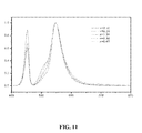
- FIG. 11 is a normalized version of the spectra of FIG. 10 ;
- FIG. 17 shows three emission spectra of the inventive chlorosilicates where one sample contains Eu 2+ but no Mn 2+ ; a second sample contains Mn 2+ ions but no Eu 2+ ions, and the third sample contained both kinds of ions; and
- FIG. 18 shows graphically the energy transfer machanism of Eu 2+ ⁇ Mn 2+ .
- chlorosilicate-based phosphors configured to emit yellow-green light in a wavelength ranging from about 500 nm to about 560 nm in response to an excitation source emitting at about 400 nm to about 480 nm, wherein the light emitted by the phosphor has a decay time ranging from about 1 millisecond (1 ms) to about 10 milliseconds (10 ms).
- the composition of the phosphor comprises Ca 8-x-y A x Eu y Mg 1-m-n B m Mn n (Si 1-s C s O 4 ) 4 R 2 , where A is at least one divalent cation including Ca, Sr, Ba, individually or in combinations, or a combination of +1 and +3 cations; B is Zn or Cd, or a divalent metal ion other than an alkaline earth, present either individually or in combinations; C is a +3, +4, or +5 cation, including at least one of Ge, Al, B, Gd, Ga, and N, either individually or in combinations, and R is a ⁇ 1, ⁇ 2, ⁇ 3 anion, including F, Cl, Br, I, either individually, or in combinations
- the value of the sum of the parameters x+y is any value less than about 8
- the value of the sum of the parameters m+n is any value less than about 1.
- the value of the s parameter is any value less than about 1.
- the decay time is created by the time it takes for a transfer of energy in a composition having both Eu 2+ and Mn 2+ ions; the transfer of energy being from an Eu 2+ ion to an Mn 2+ ion. Both types of ions function together to transfer energy efficiently; samples with no Eu 2+ will not efficiently photoluminescence, and samples with no Mn 2+ will not exhibit a decay time.
- a desired ratio of Eu 2+ ions to Mn 2+ ions is about 0.2/0.4.
- the chlorosilicate phosphor has the formula Ca 8-x Eu x Mg 1-y Mn y (SiO 4 ) 4 Cl 2 , where x ranges from about 0.16 to 0.24, and y ranges from about 0.3 to about 0.5.
- One embodiment of the invention is to use long decay phosphors on phosphors pumped by an AC driven LED or LED array.
- the LED die When a single LED or LED array is directly pumped by an AC driver, the LED die emits light constantly.
- the AC voltage applied to the LED (or array of LEDs) has to exceed a threshold value to make the LED emit light.
- the LED turns on and off at the same frequency, or a double the frequency, when the AC driving power sweeps between zero, and its peak value. This causes the LED to flicker.
- a typical AC line power has a frequency of 50 or 60 Hz, the LED will flicker at a frequency of 50 to 60 Hz, or double that frequency, 100/120 Hz.
- the presence of flickering can significantly influence the perceived quality of a light source to a human observer. Light flickering at 100/120 Hz is not normally perceived by a human, but there are concerns nonetheless.
- Modulation depth In addition to flickering at a given frequency, there is another condition known as “modulation depth” which also affects the quality of the light originating from a flickering light source. Modulation depth is defined as the ratio of deviation to the maximum light output of a light source within an AC duty cycle. Smaller modulation depths indicate that output of a light source is more uniform over time. The human eye finds it more difficult to sense the flicker from a small modulation depth light source than a maximum modulation source that is 100 percent on and off during a duty cycle.
- the LED light source continues to emit light during the decay period.
- the LED off period is normally about 1 ms to about 10 ms.
- a long decay phosphor can effectively fill the gap and reduce the modulation depth of a light source.
- a long decay phosphor (also known as a millisecond decay phosphor) is applied to a simplified DC driver that lacks a capacitor to control the ripple voltage.
- This kind of driver may be as simple as a rectifier.
- This kind of driver has the advantage of being simple and low cost, while at the same time demonstrating a long lifetime and high efficiency, and as such, it is commonly used in LED lighting.
- a long decay phosphor can improve the modulation depth of the DC driver pump LED light output when the ripple voltage is high in the driver design.
- usage of the long decay photoluminescent material will smooth out the light output from such AC lighting systems, even without a smoothing capacitor, which eliminates and/or significantly reduces flickering.
- the long decay photoluminescent material can be considered to provide optical smoothing of the light output in an analogous manner to which a capacitor provides electrical smoothing. This allows the AC-lighting system to maintain the advantage of using a simple driver without a capacitor to have a lower cost and a longer life time, while also getting avoiding unwanted AC-related artifacts such as flickering.
- a long decay phosphor e.g., millisecond decay phosphor
- PWM pulse width modulation
- Most LED dimmers use pulse width modulation to dim an LED's output, and 120 Hz is a commonly used as the dimming frequency.
- the use of a long decay phosphor in this device can make the pulse width modulation dimming more like DC dimming, which in turn reduces the flickering caused by the pulse width modulated signal.
- the phosphor when using a long decay phosphor (millisecond decay phosphor) together with an LED and the driver disclosed above, the phosphor is not necessarily packaged inside the LED. Alternatively, the phosphor may be positioned in the fixture remotely. In this embodiment, a long decay remote phosphor is used in conjunction with a blue LED.
- a long decay remote phosphor is used in conjunction with a blue LED.
- the divalent manganese ion usually emits light characteristically in the green or red region of the electromagnetic spectrum.
- the luminescence of Mn 2+ consists of broad d-d emission band which may be ascribed to the forbidden transition from the excited state 4 T 1 to the ground state 6 A 1 .
- the emission color of Mn 2 ⁇ activated compound varies from green to red with the changing of the matrix, the coordination number of Mn 2+ , and the strength of the ligand field. Due to its forbidden transition, the decay time from 4 T 1 to 6 A 1 is in milliseconds range. The decay time changes with the concentration of Mn. The decay time is reduced at higher doping Mn concentrations. However, with a higher Mn content concentration quenching can occur, and the color coordinates shift as a result. Thus, it is known that there is a trade-off between the decay time, the brightness, and the concentration of Mn.
- Mn 2+ activated compounds demonstrate only weak absorption in UV to blue region, and a sensitizer is often used in practical applications.
- the emission of Mn 2+ may be greatly enhanced by the host matrix, itself, or by addition of ions such as Eu 2+ , Pb 2+ and Ce 3+ , etc. to the host matrix.
- FIG. 1 shows the energy transfer between Eu 2+ and Mn 2+ according to the present embodiments.
- the Eu 2+ in the compound After absorbing the excitation energy from 450 nm LED chips, the Eu 2+ in the compound show an emission at around 515 nm, which is then transferred to the Mn 2+ ions, with emission at around 547 nm.
- Such energy transfer efficiency is strongly dependent on the concentration ratio between Eu 2+ and Mn 2+ ions.
- An appropriated concentration of Eu 2+ is needed in the compounds so that the energy can be transferred efficiently to Mn 2+
- the intensity ratio between Eu 2+ emission and Mn 2+ emission can be varied with different concentration ratio between Eu 2+ and Mn 2+
- the emission with peak at 515 nm can be almost eliminated and a purer color emission of Mn 2+ at 547 nm will be substantially the only emission peak observed, which is more favorable for certain applications.
- FIGS. 1-3 each show a series of x-ray diffraction (XRD) patterns of the exemplary chlorosilicates represented by the formula Ca 8-x Eu x Mg 1-y Mn y (SiO 4 ) 4 Cl 2 , where x, the Eu content, ranges from about 0.1 mol to about 0.5 mol, and the Mn content ranged from about 0.1 mol to about 0.6 mol.
- XRD x-ray diffraction
- FIG. 4 SEM (scanning electron microscopy) images of a generic chlorosilicate (Ca,Eu) 8 (Mg,Mn)(SiO 4 ) 4 Cl 2 are shown in FIG. 4 at 1000 ⁇ and 2000 ⁇ magnifications.
- the images show that the inventive chlorosilicates crystallized in a wide distribution range, starting at from less than 1 micrometer in size, up to more than 10 micrometers in size. This particle size range of ⁇ 1 ⁇ m up to >10 ⁇ m is a feasible one for the inventive chlorosilicate phosphors to be used in LED applications.
- the peak of the emission is at around 547 nm, and there is a shoulder at around 515 nm. This shows that with increasing Mn concentration, the peak at 515 nm decreased while the peak intensity of 547 nm changes.
- the peak at around 517 nm is assigned to the emission of Eu 2+ in the hosts, while the peak at around 547 nm is assigned to the emission of Mn ions in the host.
- the CIE of the emission of the inventive chlorosilicates varies at different Mn contents under both UV and blue LED excitation.
- This graph illustrates that the material displays a broad band of absorption, from the UV to about 520 nm, and thus the inventive chlorosilicates are suitable for use in both UV and blue LED based applications.
- the peak at around 517 nm is assigned to the emission of Eu 2+ in the host, while the peak at around 547 nm is assigned to the emission of Mn ions in the host.
- the CIE of the emission of the invention varies at different Mn contents under UV and blue LED excitation.
- the phosphor was packaged into a PLCC 3528 top view LED package.
- a square wave current signal was then applied to the LED to cycle it between on and off states: at an 8 ms interval for the data of FIG. 9 a , and at a 5 ms interval for the data of FIG. 9 b .
- An optical detector with a response speed of less than 1 microsecond was used to monitor the optical emission(s) of the LED.
- the decay curve attributable to the phosphor is clearly visible.
- the intensity of the emission of Mn 2 ⁇ in the invention is 43.6% and at 8 milliseconds, 34.0%, respectively.
- the peak of the emission is at around 547 nm, and there is a shoulder at around 515 nm. This shows that with increasing Mn content, the peak at 515 nm decreases while the peak intensity of 547 nm changes.
- the peak at around 517 nm is assigned to the emission of Eu 2+ in the host, while the peak at around 547 nm is assigned to the emission of Mn ions in the host.
- the CIE of the emission of the invention varies at different Mn contents under UV and blue LED excitation.
- FIG. 11 is a normalized version of the spectra of FIG. 10 .
- the normalized data also show the emission having a peak at about 547 nm, and a shoulder at around 515 nm. The same observation as before may be made in the normalized data: increasing the Mn concentration, the peak at 515 nm decreased, while the peak intensity of 547 nm changes.
- the peak at around 517 nm is assigned to the emission of Eu 2+ in the host, while the peak at around 547 nm is assigned to the emission of Mn ions in the host.
- the test method is the same as the one previously described in FIG. 9 .
- the decay curve is clearly observable even with the presence of the red phosphor.
- the test method is the same as the one previously described in FIG. 9 .
- the intensity of the LED emission is 29.8% and 26.3%, respectively, at the end of each cycle;
- This data shows that when the inventive chlorosilicates are combined with red light from a red-emitting phosphor, and blue light from a blue-emitting LED, the resultant light is white light.
- This data shows that when the inventive chlorosilicates are combined with red light from a red-emitting phosphor, and blue light from a blue-emitting LED, the resultant light is white light.
- the data shows that without Mn, the emission of the invention decreases sharply, while when Mn ions are present in the host, the emission decays in the millisecond range.
- the emission of Eu 2+ at around 515 nm can only be observed when there are no Mn 2+ ions in the host, and no emission is observed if only Mn 2+ ions are doped into the host.
- the emission of 547 nm light which is assigned to the emission of Mn 2+ , can only be observed when Eu ions are co-doped in the host.
- One of ordinary skill in the art will also note that in the Eu 2+ and Mn + co-doped host, little emission, or perhaps only a weak emission of Eu 515 nm can be observed. This implies that the presence of Eu 2+ ions in the host are necessary in order to accomplish a transfer of energy to the Mn 2+ ions.
- a number of methods may be used to synthesize the present green-emitting phosphors, which may be chlorosilicates, including solid state reaction methods, and liquid mixing method.
- Liquid mixing include such methods as co-precipitation and sol-gel techniques.
- the starting materials of Ca(NO 3 ) 2 .4H 2 O, Mg(NO 3 ) 2 .6H 2 O, NH4Cl were dissolved into 500 ml DI water, then add 33.5 ml 10.6% Eu(NO3)3 solution. The water was maintained at 60° C. and stirred;
Abstract
Description
| TABLE 1 |
| The decay time of the Mn2+ transition as a function of Mn |
| concentration in Ca7.6Eu0.4Mg1−yMny(SiO4)4Cl2 |
| Decay | |||
| time | |||
| Ca7.6Eu0.4Mg1−yMny(SiO4)4Cl2 | (ms) | ||
| y = 0.1 | 2.9 | ||
| y = 0.2 | 3.1 | ||
| y = 0.3 | 3.0 | ||
Claims (28)
Priority Applications (1)
| Application Number | Priority Date | Filing Date | Title |
|---|---|---|---|
| US13/418,229 US9085732B2 (en) | 2011-03-11 | 2012-03-12 | Millisecond decay phosphors for AC LED lighting applications |
Applications Claiming Priority (2)
| Application Number | Priority Date | Filing Date | Title |
|---|---|---|---|
| US201161451997P | 2011-03-11 | 2011-03-11 | |
| US13/418,229 US9085732B2 (en) | 2011-03-11 | 2012-03-12 | Millisecond decay phosphors for AC LED lighting applications |
Publications (2)
| Publication Number | Publication Date |
|---|---|
| US20120229038A1 US20120229038A1 (en) | 2012-09-13 |
| US9085732B2 true US9085732B2 (en) | 2015-07-21 |
Family
ID=46794904
Family Applications (1)
| Application Number | Title | Priority Date | Filing Date |
|---|---|---|---|
| US13/418,229 Expired - Fee Related US9085732B2 (en) | 2011-03-11 | 2012-03-12 | Millisecond decay phosphors for AC LED lighting applications |
Country Status (3)
| Country | Link |
|---|---|
| US (1) | US9085732B2 (en) |
| TW (1) | TWI553097B (en) |
| WO (1) | WO2012125585A1 (en) |
Cited By (1)
| Publication number | Priority date | Publication date | Assignee | Title |
|---|---|---|---|---|
| WO2019229329A1 (en) | 2018-06-01 | 2019-12-05 | Aledia | Optoelectronic circuit comprising light emitting diodes |
Families Citing this family (8)
| Publication number | Priority date | Publication date | Assignee | Title |
|---|---|---|---|---|
| WO2013112542A1 (en) | 2012-01-25 | 2013-08-01 | Intematix Corporation | Long decay phosphors for lighting applications |
| US9683169B2 (en) * | 2013-10-11 | 2017-06-20 | Performance Indicator, Llc | Smoothing phosphors for AC LED lighting |
| US10104726B2 (en) * | 2014-01-28 | 2018-10-16 | Sharp Kabushiki Kaisha | Light emitting diode drive device and illumination device |
| JP2015188050A (en) * | 2014-03-12 | 2015-10-29 | 株式会社東芝 | light-emitting device |
| TWI552132B (en) * | 2014-09-12 | 2016-10-01 | 群創光電股份有限公司 | Display apparatus and backlight driving method of the same |
| US10066160B2 (en) | 2015-05-01 | 2018-09-04 | Intematix Corporation | Solid-state white light generating lighting arrangements including photoluminescence wavelength conversion components |
| CN107710873B (en) * | 2015-06-12 | 2019-11-12 | 飞利浦照明控股有限公司 | AC-LED with mixing LED channel |
| EP3276680A1 (en) | 2017-01-25 | 2018-01-31 | Siemens Schweiz AG | Optical smoke detection based on the two colour principle using a light emitting diode with an led chip for light emission and with a light converter for converting a part of the emitted light to longer wave light |
Citations (17)
| Publication number | Priority date | Publication date | Assignee | Title |
|---|---|---|---|---|
| US5998925A (en) | 1996-07-29 | 1999-12-07 | Nichia Kagaku Kogyo Kabushiki Kaisha | Light emitting device having a nitride compound semiconductor and a phosphor containing a garnet fluorescent material |
| US6294800B1 (en) | 1998-02-06 | 2001-09-25 | General Electric Company | Phosphors for white light generation from UV emitting diodes |
| US20020146835A1 (en) | 2001-02-28 | 2002-10-10 | Home Diagnostics, Inc. | Method for determining concentration of an analyte in a test strip |
| US20040159846A1 (en) | 2003-02-18 | 2004-08-19 | Doxsee Daniel Darcy | White light LED device |
| US6945672B2 (en) | 2002-08-30 | 2005-09-20 | Gelcore Llc | LED planar light source and low-profile headlight constructed therewith |
| US7138660B2 (en) | 2000-12-28 | 2006-11-21 | Toyoda Gosei Co., Ltd. | Light emitting device |
| US7213942B2 (en) | 2002-10-24 | 2007-05-08 | Ac Led Lighting, L.L.C. | Light emitting diodes for high AC voltage operation and general lighting |
| US7309151B2 (en) | 2005-04-11 | 2007-12-18 | Avago Technologies Ecbu Ip (Singapore) Pte. Ltd. | Light emitting panel |
| US7740514B2 (en) | 2004-03-30 | 2010-06-22 | Lumination Llc | LED illumination device with layered phosphor pattern |
| US7786659B2 (en) | 2007-08-31 | 2010-08-31 | Hitachi, Ltd. | Plasma display with a novel green-silicate phosphor |
| US20100219428A1 (en) | 2008-07-29 | 2010-09-02 | Seoul Semiconductor Co., Ltd. | Warm white light emitting apparatus and back light module comprising the same |
| US20100295458A1 (en) | 2009-05-22 | 2010-11-25 | Advanced-Connectek Inc. | Ac led module with an improved power factor |
| US8188687B2 (en) * | 2005-06-28 | 2012-05-29 | Seoul Opto Device Co., Ltd. | Light emitting device for AC power operation |
| US8324840B2 (en) * | 2009-06-04 | 2012-12-04 | Point Somee Limited Liability Company | Apparatus, method and system for providing AC line power to lighting devices |
| US20130187556A1 (en) | 2012-01-25 | 2013-07-25 | Intemetix Corporation | Long Decay Phosphors for Lighting Applications |
| US8497621B2 (en) * | 2007-09-24 | 2013-07-30 | Osram Gesellschaft Mit Beschraenkter Haftung | Illuminating device with light buffer |
| US8807799B2 (en) | 2010-06-11 | 2014-08-19 | Intematix Corporation | LED-based lamps |
Family Cites Families (1)
| Publication number | Priority date | Publication date | Assignee | Title |
|---|---|---|---|---|
| US7573072B2 (en) * | 2004-03-10 | 2009-08-11 | Lumination Llc | Phosphor and blends thereof for use in LEDs |
-
2012
- 2012-03-12 US US13/418,229 patent/US9085732B2/en not_active Expired - Fee Related
- 2012-03-12 TW TW101108346A patent/TWI553097B/en not_active IP Right Cessation
- 2012-03-12 WO PCT/US2012/028817 patent/WO2012125585A1/en active Application Filing
Patent Citations (19)
| Publication number | Priority date | Publication date | Assignee | Title |
|---|---|---|---|---|
| US5998925A (en) | 1996-07-29 | 1999-12-07 | Nichia Kagaku Kogyo Kabushiki Kaisha | Light emitting device having a nitride compound semiconductor and a phosphor containing a garnet fluorescent material |
| US6294800B1 (en) | 1998-02-06 | 2001-09-25 | General Electric Company | Phosphors for white light generation from UV emitting diodes |
| US7138660B2 (en) | 2000-12-28 | 2006-11-21 | Toyoda Gosei Co., Ltd. | Light emitting device |
| US7157746B2 (en) | 2000-12-28 | 2007-01-02 | Toyoda Gosei Co., Ltd. | Light emitting device having a divalent-europium-activated alkaline earth metal orthosilicate phosphor |
| US7679101B2 (en) | 2000-12-28 | 2010-03-16 | Toyoda Gosei Co., Ltd. | Light emitting device |
| US20020146835A1 (en) | 2001-02-28 | 2002-10-10 | Home Diagnostics, Inc. | Method for determining concentration of an analyte in a test strip |
| US6945672B2 (en) | 2002-08-30 | 2005-09-20 | Gelcore Llc | LED planar light source and low-profile headlight constructed therewith |
| US7213942B2 (en) | 2002-10-24 | 2007-05-08 | Ac Led Lighting, L.L.C. | Light emitting diodes for high AC voltage operation and general lighting |
| US20040159846A1 (en) | 2003-02-18 | 2004-08-19 | Doxsee Daniel Darcy | White light LED device |
| US7740514B2 (en) | 2004-03-30 | 2010-06-22 | Lumination Llc | LED illumination device with layered phosphor pattern |
| US7309151B2 (en) | 2005-04-11 | 2007-12-18 | Avago Technologies Ecbu Ip (Singapore) Pte. Ltd. | Light emitting panel |
| US8188687B2 (en) * | 2005-06-28 | 2012-05-29 | Seoul Opto Device Co., Ltd. | Light emitting device for AC power operation |
| US7786659B2 (en) | 2007-08-31 | 2010-08-31 | Hitachi, Ltd. | Plasma display with a novel green-silicate phosphor |
| US8497621B2 (en) * | 2007-09-24 | 2013-07-30 | Osram Gesellschaft Mit Beschraenkter Haftung | Illuminating device with light buffer |
| US20100219428A1 (en) | 2008-07-29 | 2010-09-02 | Seoul Semiconductor Co., Ltd. | Warm white light emitting apparatus and back light module comprising the same |
| US20100295458A1 (en) | 2009-05-22 | 2010-11-25 | Advanced-Connectek Inc. | Ac led module with an improved power factor |
| US8324840B2 (en) * | 2009-06-04 | 2012-12-04 | Point Somee Limited Liability Company | Apparatus, method and system for providing AC line power to lighting devices |
| US8807799B2 (en) | 2010-06-11 | 2014-08-19 | Intematix Corporation | LED-based lamps |
| US20130187556A1 (en) | 2012-01-25 | 2013-07-25 | Intemetix Corporation | Long Decay Phosphors for Lighting Applications |
Non-Patent Citations (2)
| Title |
|---|
| International Searching Authority, International Search Report and Written Opinion for PCT/US2012/028817, Jul. 11, 2012, 13 pages. |
| Liu et al., "Luminescence and energy transfer in Ca3Sc2Si3O12:Ce3+, Mn2+white LED phosphors," Journal of Luminescence, Dec. 24, 2011 (e-publication), vol. 133, pp. 21-24. |
Cited By (1)
| Publication number | Priority date | Publication date | Assignee | Title |
|---|---|---|---|---|
| WO2019229329A1 (en) | 2018-06-01 | 2019-12-05 | Aledia | Optoelectronic circuit comprising light emitting diodes |
Also Published As
| Publication number | Publication date |
|---|---|
| TWI553097B (en) | 2016-10-11 |
| WO2012125585A1 (en) | 2012-09-20 |
| TW201245416A (en) | 2012-11-16 |
| US20120229038A1 (en) | 2012-09-13 |
Similar Documents
| Publication | Publication Date | Title |
|---|---|---|
| US9085732B2 (en) | Millisecond decay phosphors for AC LED lighting applications | |
| US9089037B2 (en) | Long decay phosphors for lighting applications | |
| JP3993854B2 (en) | Semiconductor light emitting element and light emitting device using the same | |
| JP3985486B2 (en) | Semiconductor light emitting element and light emitting device using the same | |
| EP1815536B1 (en) | Light source with improved dimming behavior and method of driving the light source | |
| US20090020775A1 (en) | RED LINE EMITTING COMPLEX FLUORIDE PHOSPHORS ACTIVATED WITH Mn4+ | |
| Yim et al. | A novel blue-emitting NaSrPO4: Eu2+ phosphor for near UV based white light-emitting-diodes | |
| JP2017527114A (en) | Incandescent dimming light emitting diode | |
| CN107710873B (en) | AC-LED with mixing LED channel | |
| KR20130125775A (en) | Ac white led device | |
| JP6201848B2 (en) | Phosphor, phosphor-containing composition, light emitting device, illumination device, and liquid crystal display device | |
| JP2005150691A (en) | Light-emitting device and phosphor | |
| US20050247951A1 (en) | White light-emitting device | |
| JP2004221185A (en) | Light emitting device, lighting apparatus and display using same | |
| JP2004266201A (en) | Light emitting device and luminaire using it | |
| JP2004235546A (en) | Light emitting device and lighting device and display using it | |
| KR100672972B1 (en) | White diode | |
| US20090026918A1 (en) | Novel phosphor and fabrication of the same | |
| US8362689B2 (en) | Phosphors and light-emitting devices using the same | |
| JP2015183084A (en) | Fluorescent material for violet ray excitation, composition containing fluorescent material and light-emitting device using the fluorescent material and lightening apparatus and picture display unit using the light-emitting device | |
| JP2015002182A (en) | Illumination apparatus | |
| KR102113044B1 (en) | Lithium-based garnet phosphor, preparing method of the same, and luminescent property of the same | |
| KR100571882B1 (en) | Yellow phospher and white light emitting device comprising it | |
| CN100411200C (en) | White light emitting device | |
| Stone | An investigation into novel red emitting phosphors and their applications |
Legal Events
| Date | Code | Title | Description |
|---|---|---|---|
| AS | Assignment |
Owner name: GP MEDICAL, INC., CALIFORNIA Free format text: ASSIGNMENT OF ASSIGNORS INTEREST;ASSIGNORS:SUNG, HSING-WEN;SONAJE, KIRAN;NGUYEN, HO-NGOC;AND OTHERS;SIGNING DATES FROM 20120330 TO 20120402;REEL/FRAME:028001/0317 |
|
| AS | Assignment |
Owner name: INTEMATIX CORPORATION, CALIFORNIA Free format text: ASSIGNMENT OF ASSIGNORS INTEREST;ASSIGNORS:ZENG, QINGHUA;WANG, GANG;LI, YI-QUN;REEL/FRAME:028256/0881 Effective date: 20120312 |
|
| STCF | Information on status: patent grant |
Free format text: PATENTED CASE |
|
| AS | Assignment |
Owner name: EAST WEST BANK, CALIFORNIA Free format text: SECURITY INTEREST;ASSIGNORS:INTEMATIX HONG KONG CO. LIMITED;INTEMATIX CORPORATION;REEL/FRAME:036967/0623 Effective date: 20151022 |
|
| FEPP | Fee payment procedure |
Free format text: MAINTENANCE FEE REMINDER MAILED (ORIGINAL EVENT CODE: REM.); ENTITY STATUS OF PATENT OWNER: SMALL ENTITY |
|
| FEPP | Fee payment procedure |
Free format text: SURCHARGE FOR LATE PAYMENT, SMALL ENTITY (ORIGINAL EVENT CODE: M2554); ENTITY STATUS OF PATENT OWNER: SMALL ENTITY |
|
| MAFP | Maintenance fee payment |
Free format text: PAYMENT OF MAINTENANCE FEE, 4TH YR, SMALL ENTITY (ORIGINAL EVENT CODE: M2551); ENTITY STATUS OF PATENT OWNER: SMALL ENTITY Year of fee payment: 4 |
|
| FEPP | Fee payment procedure |
Free format text: ENTITY STATUS SET TO UNDISCOUNTED (ORIGINAL EVENT CODE: BIG.); ENTITY STATUS OF PATENT OWNER: LARGE ENTITY |
|
| AS | Assignment |
Owner name: INTEMATIX CORPORATION, CALIFORNIA Free format text: RELEASE BY SECURED PARTY;ASSIGNOR:EAST WEST BANK;REEL/FRAME:059910/0304 Effective date: 20220414 Owner name: INTEMATIX HONG KONG CO. LIMITED, CALIFORNIA Free format text: RELEASE BY SECURED PARTY;ASSIGNOR:EAST WEST BANK;REEL/FRAME:059910/0304 Effective date: 20220414 |
|
| FEPP | Fee payment procedure |
Free format text: MAINTENANCE FEE REMINDER MAILED (ORIGINAL EVENT CODE: REM.); ENTITY STATUS OF PATENT OWNER: LARGE ENTITY |
|
| LAPS | Lapse for failure to pay maintenance fees |
Free format text: PATENT EXPIRED FOR FAILURE TO PAY MAINTENANCE FEES (ORIGINAL EVENT CODE: EXP.); ENTITY STATUS OF PATENT OWNER: LARGE ENTITY |
|
| STCH | Information on status: patent discontinuation |
Free format text: PATENT EXPIRED DUE TO NONPAYMENT OF MAINTENANCE FEES UNDER 37 CFR 1.362 |
|
| FP | Lapsed due to failure to pay maintenance fee |
Effective date: 20230721 |