US9091375B1 - Abrasion-resistant braided hose - Google Patents
Abrasion-resistant braided hose Download PDFInfo
- Publication number
- US9091375B1 US9091375B1 US14/549,939 US201414549939A US9091375B1 US 9091375 B1 US9091375 B1 US 9091375B1 US 201414549939 A US201414549939 A US 201414549939A US 9091375 B1 US9091375 B1 US 9091375B1
- Authority
- US
- United States
- Prior art keywords
- hose
- abrasion
- resistant
- inner hose
- braided
- Prior art date
- Legal status (The legal status is an assumption and is not a legal conclusion. Google has not performed a legal analysis and makes no representation as to the accuracy of the status listed.)
- Expired - Fee Related
Links
Images


Classifications
-
- F—MECHANICAL ENGINEERING; LIGHTING; HEATING; WEAPONS; BLASTING
- F16—ENGINEERING ELEMENTS AND UNITS; GENERAL MEASURES FOR PRODUCING AND MAINTAINING EFFECTIVE FUNCTIONING OF MACHINES OR INSTALLATIONS; THERMAL INSULATION IN GENERAL
- F16L—PIPES; JOINTS OR FITTINGS FOR PIPES; SUPPORTS FOR PIPES, CABLES OR PROTECTIVE TUBING; MEANS FOR THERMAL INSULATION IN GENERAL
- F16L11/00—Hoses, i.e. flexible pipes
- F16L11/02—Hoses, i.e. flexible pipes made of fibres or threads, e.g. of textile which may or may not be impregnated, or provided with an impermeable layer, e.g. fire-hoses
-
- F—MECHANICAL ENGINEERING; LIGHTING; HEATING; WEAPONS; BLASTING
- F16—ENGINEERING ELEMENTS AND UNITS; GENERAL MEASURES FOR PRODUCING AND MAINTAINING EFFECTIVE FUNCTIONING OF MACHINES OR INSTALLATIONS; THERMAL INSULATION IN GENERAL
- F16L—PIPES; JOINTS OR FITTINGS FOR PIPES; SUPPORTS FOR PIPES, CABLES OR PROTECTIVE TUBING; MEANS FOR THERMAL INSULATION IN GENERAL
- F16L11/00—Hoses, i.e. flexible pipes
- F16L11/04—Hoses, i.e. flexible pipes made of rubber or flexible plastics
- F16L11/08—Hoses, i.e. flexible pipes made of rubber or flexible plastics with reinforcements embedded in the wall
- F16L11/088—Hoses, i.e. flexible pipes made of rubber or flexible plastics with reinforcements embedded in the wall comprising a combination of one or more layers of a helically wound cord or wire with one or more braided layers
-
- F—MECHANICAL ENGINEERING; LIGHTING; HEATING; WEAPONS; BLASTING
- F16—ENGINEERING ELEMENTS AND UNITS; GENERAL MEASURES FOR PRODUCING AND MAINTAINING EFFECTIVE FUNCTIONING OF MACHINES OR INSTALLATIONS; THERMAL INSULATION IN GENERAL
- F16L—PIPES; JOINTS OR FITTINGS FOR PIPES; SUPPORTS FOR PIPES, CABLES OR PROTECTIVE TUBING; MEANS FOR THERMAL INSULATION IN GENERAL
- F16L11/00—Hoses, i.e. flexible pipes
- F16L11/04—Hoses, i.e. flexible pipes made of rubber or flexible plastics
- F16L11/12—Hoses, i.e. flexible pipes made of rubber or flexible plastics with arrangements for particular purposes, e.g. specially profiled, with protecting layer, heated, electrically conducting
- F16L11/122—Hoses provided with integrated fixing means, e.g. hooks
Definitions
- This invention relates to braided hoses and more particularly a hose having an abrasion-resistant middle layer located between a braided covering and an inner hose to protect the inner hose from ruptures caused from abrasions.
- Braided hoses are commonly used in industrial and other type applications as supply, drainage and/or exhaust lines.
- Such hoses normally have an inner hose made of rubber or metal (such as corrugated hoses) with an outer layer of braided metal threads.
- the threads may also be made of other material depending on the intended use of the hose and economic considerations.
- Couplings are preferably located on each end of the hose.
- the method by which the braiding is attached to the couplings or connection fittings depends on the type of fitting and the demands on the hose.
- Hose braiding The main purpose of braiding is to increase pressure resistance in the hose. Due to its inherent flexibility, the braiding moulds itself to the movement of the hose. Hose braiding consists of wrapped wire bundles that are alternately layered one over the other. This not only prevents hose lengthening due to internal pressure, but also absorbs external tensile forces and protects the outside of the hose. The braiding also greatly increases the resistance of the hose to internal pressure.
- Patent No. Inventor Issue/Publication Date U.S. Pat. References
- 3,023,787 Phillips et al. Mar. 6, 1962 3,190,315 Taylor et al. Jun. 22, 1965 3,564,967 Atwell et al. Apr. 11, 1972 5,381,511 Bahar et al. Jan. 10, 1995 6,302,152 Mulligan Oct. 16, 2001 6,334,466 Jani et al. Jan. 1, 2002 7,588,057 Bentley Sep. 15, 2009
- the primary object of the present invention is to provide an abrasion-resistant braided hose wherein the structural integrity of the inner hose is not compromised by the braiding surrounding the inner hose.
- the present invention fulfills the above and other objects by providing an abrasion-resistant braided hose having an anti-abrasion layer located between an inner hose and a braiding covering.
- the abrasion-resistant layer is preferably a strip of Teflon® helically or spirally wrapped around the inner hose to allow for flexibility or may be a stripwound interlocking hose.
- the abrasion-resistant layer reduces the amount of friction between the inner hose and the braided covering, thereby reducing the likelihood of the inner hose rupturing and failing, especially in situations where the abrasion-resistant braided hose is exposed to high vibrations and/or pulsating environments, for example, in use with compressors, reciprocating engines and so forth.
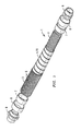
- FIG. 1 is a perspective side view of an abrasion-resistant braided hose of the present invention
- FIG. 2 is an exploded perspective side view of an abrasion-resistant braided hose of the present invention.
- FIG. 3 is an exploded perspective side view of an abrasion-resistant braided hose of the present invention having a stripwound interlocking hose as an abrasion-resistant middle layer.
- the abrasion-resistant braided hose 1 comprises an inner hose 2 , which may be a rubber hose, a metal hose, a strip wound hose, a corrugated hose (as illustrated here) or other types of hose.
- An outer braided covering 3 comprised of a plurality of braided threads surrounds the inner hose 2 .
- An abrasion-resistant middle layer 4 is located between the braided covering 3 and the inner hose 2 .
- the abrasion-resistant middle layer 4 is preferably a polytetrafluoroethylene, such as Teflon®, or other material that reduces friction between the inner hose 2 and the braided covering 3 .
- the abrasion-resistant middle layer 4 is an elongated strip of tape 5 wrapped around the inner hose 2 , thereby separating the inner hose 2 from the braided covering 3 .
- the elongated strip of tape 5 is wrapped in a helical or spiral pattern around the inner hose 2 .
- the abrasion-resistant middle layer 4 may also have a coating of additional lubricant on an outer surface to further reduce friction between the inner hose 2 , and the braided covering 3 .
- the abrasion-resistant middle layer 4 may also be a stripwound interlocking hose 11 , as illustrated in FIG. 3 .
- the assembly of the abrasion-resistant braided hose 1 is accomplished by cutting the inner hose 2 to a desired length.
- individual bands 6 of the braided covering 3 are cut to an appropriate length to be braided around the cut inner hose 2 .
- the tape 5 forming the abrasion-resistant middle layer 4 is then wound around the inner hose 2 in a spiral fashion leaving space for inner rings 7 to be connected to ends of the inner tube 2 .
- the inner rings 7 are then connected or swaged in place to the ends of the inner hose 2 .
- the braided covering 3 is then placed over the abrasion-resistant middle layer 4 .
- braid rings 8 are placed over ends of the braided covering 3 and the ends of the abrasion-resistant braided hose 1 are sealed preferably by seals 10 , such as welds.
- End fittings 9 such as a threaded end fittings, flanged end fittings, welded end fittings and so forth, are then secured to the ends of the abrasion-resistant braided hose 1 , preferably by welding.
Abstract
Description
| Patent No. | Inventor | Issue/Publication Date | ||
| (U.S. Pat. References) |
| 3,023,787 | Phillips et al. | Mar. 6, 1962 | ||
| 3,190,315 | Taylor et al. | Jun. 22, 1965 | ||
| 3,564,967 | Atwell et al. | Apr. 11, 1972 | ||
| 5,381,511 | Bahar et al. | Jan. 10, 1995 | ||
| 6,302,152 | Mulligan | Oct. 16, 2001 | ||
| 6,334,466 | Jani et al. | Jan. 1, 2002 | ||
| 7,588,057 | Bentley | Sep. 15, 2009 | ||
-
- 1. abrasion-resistant braided hose, generally
- 2. inner hose
- 3. braided covering
- 4. abrasion-resistant middle layer
- 5. tape
- 6. individual band
- 7. inner rings
- 8. braid rings
- 9. end fittings
- 10. seal
- 11. stripwound interlocking hose
Claims (6)
Priority Applications (3)
| Application Number | Priority Date | Filing Date | Title |
|---|---|---|---|
| US14/549,939 US9091375B1 (en) | 2014-08-05 | 2014-11-21 | Abrasion-resistant braided hose |
| US14/725,378 US9234609B1 (en) | 2014-08-05 | 2015-05-29 | Abrasion-resistant braided hose |
| PCT/US2015/041440 WO2016022288A1 (en) | 2014-08-05 | 2015-07-22 | Abrasion-resistant braided hose |
Applications Claiming Priority (2)
| Application Number | Priority Date | Filing Date | Title |
|---|---|---|---|
| US201462033370P | 2014-08-05 | 2014-08-05 | |
| US14/549,939 US9091375B1 (en) | 2014-08-05 | 2014-11-21 | Abrasion-resistant braided hose |
Related Child Applications (1)
| Application Number | Title | Priority Date | Filing Date |
|---|---|---|---|
| US14/725,378 Continuation US9234609B1 (en) | 2014-08-05 | 2015-05-29 | Abrasion-resistant braided hose |
Publications (1)
| Publication Number | Publication Date |
|---|---|
| US9091375B1 true US9091375B1 (en) | 2015-07-28 |
Family
ID=53638377
Family Applications (2)
| Application Number | Title | Priority Date | Filing Date |
|---|---|---|---|
| US14/549,939 Expired - Fee Related US9091375B1 (en) | 2014-08-05 | 2014-11-21 | Abrasion-resistant braided hose |
| US14/725,378 Expired - Fee Related US9234609B1 (en) | 2014-08-05 | 2015-05-29 | Abrasion-resistant braided hose |
Family Applications After (1)
| Application Number | Title | Priority Date | Filing Date |
|---|---|---|---|
| US14/725,378 Expired - Fee Related US9234609B1 (en) | 2014-08-05 | 2015-05-29 | Abrasion-resistant braided hose |
Country Status (2)
| Country | Link |
|---|---|
| US (2) | US9091375B1 (en) |
| WO (1) | WO2016022288A1 (en) |
Cited By (1)
| Publication number | Priority date | Publication date | Assignee | Title |
|---|---|---|---|---|
| USD942595S1 (en) * | 2016-04-25 | 2022-02-01 | Eaton Intelligent Power Limited | Hose assembly with reinforced fire sleeve |
Families Citing this family (1)
| Publication number | Priority date | Publication date | Assignee | Title |
|---|---|---|---|---|
| USD947133S1 (en) * | 2019-04-11 | 2022-03-29 | Norman R. Byrne | Woven cover for electrical conduit |
Citations (18)
| Publication number | Priority date | Publication date | Assignee | Title |
|---|---|---|---|---|
| US3023787A (en) | 1957-10-31 | 1962-03-06 | Titeflex Inc | Reinforced flexible plastic hose and method of making |
| US3190315A (en) | 1962-09-10 | 1965-06-22 | Goodyear Tire & Rubber | Hose |
| US3654967A (en) | 1970-07-17 | 1972-04-11 | Uniroyal Inc | Textile-reinforced all-polymeric hose and method of making same |
| US3857415A (en) * | 1970-09-15 | 1974-12-31 | Everflex Prod Inc | Reinforced convoluted tubing of polytetrafluoroethylene |
| US4137949A (en) * | 1977-05-11 | 1979-02-06 | General Electric Company | Method of making a fire retardant conduit |
| US4190088A (en) * | 1978-03-08 | 1980-02-26 | Titeflex Corporation | Chafe or fire sleeve for hose |
| US4259989A (en) * | 1979-06-06 | 1981-04-07 | Titeflex Corporation | Chafe or fire sleeve for hose |
| US4259991A (en) * | 1979-09-20 | 1981-04-07 | Automation Industries, Inc. | High pressure hose construction and method of and apparatus for making the same |
| US4488577A (en) * | 1982-09-30 | 1984-12-18 | Parker-Hannifin Corporation | Fire resistant hose |
| US4675221A (en) * | 1978-03-08 | 1987-06-23 | Titeflex Corporation | Fire sleeve for hose |
| US5381511A (en) | 1993-06-02 | 1995-01-10 | W. L. Gore & Associates, Inc. | Flexible electrically heatable hose |
| US5507320A (en) * | 1994-10-14 | 1996-04-16 | Plumley Companies, Inc. | Hose for an automobile fuel line |
| US5782270A (en) * | 1995-05-12 | 1998-07-21 | Engineered Transistions, Inc. | Field repairable conduit termination system |
| US5931200A (en) * | 1996-06-12 | 1999-08-03 | Lsp Products Group, Inc. | Connector system for attachment of flexible hose to PEX supply line |
| US6302152B1 (en) | 1999-11-18 | 2001-10-16 | Brass-Craft Manufacturing Company | Flexible connector with improved braided sheathing |
| US6334466B1 (en) | 1998-10-09 | 2002-01-01 | The Gates Corporation | Abrasion-resistant material handling hose |
| US20050211325A1 (en) * | 2004-03-29 | 2005-09-29 | Yuji Takagi | Composite hose with a corrugated metal tube |
| US7588057B2 (en) | 2006-08-01 | 2009-09-15 | Teleflex Fluid Systems, Inc. | Insulated hose assembly and method of manufacture |
Family Cites Families (6)
| Publication number | Priority date | Publication date | Assignee | Title |
|---|---|---|---|---|
| US5413147A (en) * | 1993-04-29 | 1995-05-09 | Parker-Hannifin Corporation | Flexible hose and fitting assembly |
| US5381834A (en) * | 1993-09-14 | 1995-01-17 | Teleflex Incorporated | Hose assembly including reinforced layer having wear reducing fibers |
| AUPP228298A0 (en) * | 1998-03-12 | 1998-04-09 | Spiral Guard Australia Pty Ltd | A sheath |
| JP2001263543A (en) * | 2000-03-21 | 2001-09-26 | Tokai Rubber Ind Ltd | Impermeable composite hose |
| GB2365095A (en) * | 2000-07-29 | 2002-02-13 | Federal Mogul Technology Ltd | Flexible protective sleeve |
| US8844580B2 (en) * | 2009-03-31 | 2014-09-30 | Parker-Hannifin Corporation | Low fluid permeation rubber hose |
-
2014
- 2014-11-21 US US14/549,939 patent/US9091375B1/en not_active Expired - Fee Related
-
2015
- 2015-05-29 US US14/725,378 patent/US9234609B1/en not_active Expired - Fee Related
- 2015-07-22 WO PCT/US2015/041440 patent/WO2016022288A1/en active Application Filing
Patent Citations (19)
| Publication number | Priority date | Publication date | Assignee | Title |
|---|---|---|---|---|
| US3023787A (en) | 1957-10-31 | 1962-03-06 | Titeflex Inc | Reinforced flexible plastic hose and method of making |
| US3190315A (en) | 1962-09-10 | 1965-06-22 | Goodyear Tire & Rubber | Hose |
| US3654967A (en) | 1970-07-17 | 1972-04-11 | Uniroyal Inc | Textile-reinforced all-polymeric hose and method of making same |
| US3857415A (en) * | 1970-09-15 | 1974-12-31 | Everflex Prod Inc | Reinforced convoluted tubing of polytetrafluoroethylene |
| US4137949A (en) * | 1977-05-11 | 1979-02-06 | General Electric Company | Method of making a fire retardant conduit |
| US4675221A (en) * | 1978-03-08 | 1987-06-23 | Titeflex Corporation | Fire sleeve for hose |
| US4190088A (en) * | 1978-03-08 | 1980-02-26 | Titeflex Corporation | Chafe or fire sleeve for hose |
| US4259989A (en) * | 1979-06-06 | 1981-04-07 | Titeflex Corporation | Chafe or fire sleeve for hose |
| US4259991A (en) * | 1979-09-20 | 1981-04-07 | Automation Industries, Inc. | High pressure hose construction and method of and apparatus for making the same |
| US4488577A (en) * | 1982-09-30 | 1984-12-18 | Parker-Hannifin Corporation | Fire resistant hose |
| US5381511A (en) | 1993-06-02 | 1995-01-10 | W. L. Gore & Associates, Inc. | Flexible electrically heatable hose |
| US5507320A (en) * | 1994-10-14 | 1996-04-16 | Plumley Companies, Inc. | Hose for an automobile fuel line |
| US5782270A (en) * | 1995-05-12 | 1998-07-21 | Engineered Transistions, Inc. | Field repairable conduit termination system |
| US5931200A (en) * | 1996-06-12 | 1999-08-03 | Lsp Products Group, Inc. | Connector system for attachment of flexible hose to PEX supply line |
| US6334466B1 (en) | 1998-10-09 | 2002-01-01 | The Gates Corporation | Abrasion-resistant material handling hose |
| US6302152B1 (en) | 1999-11-18 | 2001-10-16 | Brass-Craft Manufacturing Company | Flexible connector with improved braided sheathing |
| US20050211325A1 (en) * | 2004-03-29 | 2005-09-29 | Yuji Takagi | Composite hose with a corrugated metal tube |
| US7114526B2 (en) * | 2004-03-29 | 2006-10-03 | Tokai Rubber Industries, Inc. | Composite hose with a corrugated metal tube |
| US7588057B2 (en) | 2006-08-01 | 2009-09-15 | Teleflex Fluid Systems, Inc. | Insulated hose assembly and method of manufacture |
Cited By (1)
| Publication number | Priority date | Publication date | Assignee | Title |
|---|---|---|---|---|
| USD942595S1 (en) * | 2016-04-25 | 2022-02-01 | Eaton Intelligent Power Limited | Hose assembly with reinforced fire sleeve |
Also Published As
| Publication number | Publication date |
|---|---|
| WO2016022288A1 (en) | 2016-02-11 |
| US9234609B1 (en) | 2016-01-12 |
Similar Documents
| Publication | Publication Date | Title |
|---|---|---|
| US3687169A (en) | Flexible pipe for conveying fluids, particularly hydrocarbons | |
| US5730188A (en) | Flexible conduit | |
| US3623513A (en) | High-pressure flexible hose sheath | |
| US7114526B2 (en) | Composite hose with a corrugated metal tube | |
| US11898662B2 (en) | High performance aramid braided hose | |
| US9091375B1 (en) | Abrasion-resistant braided hose | |
| JP6889992B2 (en) | Fluid pressure actuator | |
| WO2010106110A3 (en) | Improved composite hose and method for fabricating such a hose | |
| US7086419B2 (en) | Composite hose with a corrugated metal tube | |
| CN103115202A (en) | Multilayer flexible composite tube for oil field and preparation method thereof | |
| US1980466A (en) | Hose connection | |
| US2748804A (en) | Reinforced hose | |
| CN103104762A (en) | Armor pipeline | |
| US20190154174A1 (en) | Fire zone hoses and methods for forming the same | |
| US11028946B2 (en) | Fluid permeable hose carcass | |
| US2908295A (en) | Flexible pipes | |
| WO2020037353A1 (en) | A hose shroud | |
| CN209115826U (en) | A kind of hydraulic rubber pipe | |
| JP2017180636A (en) | Metal flexible tube with joint | |
| JP6286310B2 (en) | gasket | |
| US1676036A (en) | Pipe coupling | |
| CN110506177B (en) | Metal braided hose | |
| JP2021067312A (en) | Method for setting minimum bending radius of hose, and hose | |
| US11796118B2 (en) | Flexible vacuum-insulated line | |
| CA3008762C (en) | Gimbal hose |
Legal Events
| Date | Code | Title | Description |
|---|---|---|---|
| AS | Assignment |
Owner name: MICROFLEX, INC., FLORIDA Free format text: ASSIGNMENT OF ASSIGNORS INTEREST;ASSIGNORS:ATANASOSKI, JOSIF;DEBLASI, ITALO;REEL/FRAME:034230/0009 Effective date: 20141110 |
|
| STCF | Information on status: patent grant |
Free format text: PATENTED CASE |
|
| CC | Certificate of correction | ||
| MAFP | Maintenance fee payment |
Free format text: PAYMENT OF MAINTENANCE FEE, 4TH YR, SMALL ENTITY (ORIGINAL EVENT CODE: M2551); ENTITY STATUS OF PATENT OWNER: SMALL ENTITY Year of fee payment: 4 |
|
| FEPP | Fee payment procedure |
Free format text: MAINTENANCE FEE REMINDER MAILED (ORIGINAL EVENT CODE: REM.); ENTITY STATUS OF PATENT OWNER: SMALL ENTITY |
|
| LAPS | Lapse for failure to pay maintenance fees |
Free format text: PATENT EXPIRED FOR FAILURE TO PAY MAINTENANCE FEES (ORIGINAL EVENT CODE: EXP.); ENTITY STATUS OF PATENT OWNER: SMALL ENTITY |
|
| STCH | Information on status: patent discontinuation |
Free format text: PATENT EXPIRED DUE TO NONPAYMENT OF MAINTENANCE FEES UNDER 37 CFR 1.362 |
|
| FP | Lapsed due to failure to pay maintenance fee |
Effective date: 20230728 |