US9091671B2 - Liquid suction device - Google Patents
Liquid suction device Download PDFInfo
- Publication number
- US9091671B2 US9091671B2 US13/580,674 US201013580674A US9091671B2 US 9091671 B2 US9091671 B2 US 9091671B2 US 201013580674 A US201013580674 A US 201013580674A US 9091671 B2 US9091671 B2 US 9091671B2
- Authority
- US
- United States
- Prior art keywords
- pipe
- fixing member
- pipe fixing
- resilient members
- liquid suction
- Prior art date
- Legal status (The legal status is an assumption and is not a legal conclusion. Google has not performed a legal analysis and makes no representation as to the accuracy of the status listed.)
- Expired - Fee Related, expires
Links
Images


Classifications
-
- G—PHYSICS
- G01—MEASURING; TESTING
- G01N—INVESTIGATING OR ANALYSING MATERIALS BY DETERMINING THEIR CHEMICAL OR PHYSICAL PROPERTIES
- G01N35/00—Automatic analysis not limited to methods or materials provided for in any single one of groups G01N1/00 - G01N33/00; Handling materials therefor
- G01N35/10—Devices for transferring samples or any liquids to, in, or from, the analysis apparatus, e.g. suction devices, injection devices
- G01N35/1009—Characterised by arrangements for controlling the aspiration or dispense of liquids
- G01N35/1011—Control of the position or alignment of the transfer device
-
- G—PHYSICS
- G01—MEASURING; TESTING
- G01N—INVESTIGATING OR ANALYSING MATERIALS BY DETERMINING THEIR CHEMICAL OR PHYSICAL PROPERTIES
- G01N21/00—Investigating or analysing materials by the use of optical means, i.e. using sub-millimetre waves, infrared, visible or ultraviolet light
- G01N21/62—Systems in which the material investigated is excited whereby it emits light or causes a change in wavelength of the incident light
- G01N21/63—Systems in which the material investigated is excited whereby it emits light or causes a change in wavelength of the incident light optically excited
- G01N21/64—Fluorescence; Phosphorescence
- G01N21/6428—Measuring fluorescence of fluorescent products of reactions or of fluorochrome labelled reactive substances, e.g. measuring quenching effects, using measuring "optrodes"
Definitions
- the present invention relates to a liquid suction device used for liquid suction of a sample or a reagent.
- liquid of a sample or a reagent is dispensed into sample containers through a suction discharge operation.
- a suction discharge operation liquid of a sample or a reagent, diluted solution, or cleaning solution stored in many small holes of many test tubes or microplates is sucked into a suction discharge nozzle, and the sucked liquid is discharged into other containers or small holes.
- Automation of this suction discharge operation is accomplished by implementing a suction discharge system including a suction discharge nozzle movable in the depth direction (Z direction) of a container and in the plane direction (X-Y direction) where many containers are arranged laterally and longitudinally, and a pump connecting to the nozzle via a pipe.
- the suction discharge system moves the suction discharge nozzle downward into a container, and puts the nozzle tip end into liquid in the container, so as to suck the liquid.
- a slight clearance is secured between the nozzle tip end and the bottom surface of the container, so as to prevent damage to the nozzle tip end and the bottom of the container due to collision therebetween.
- a sufficient clearance between the nozzle tip end and the bottom surface of the container facilitates positioning of the nozzle tip end in the Z direction and reduces variation in the size of sample containers due to mass production, and also reduces strictness of positioning the sample containers in the suction discharge system.
- Patent Literature 1 discloses a method for preventing damage to the nozzle, and when the nozzle tip end collides with an obstacle, this method moves the nozzle and the pipe upward so that the pipe abuts to a spring-loaded earth plate, thereby stopping the aim from moving downward.
- Patent Literature 2 discloses a method for allowing a nozzle tip end to elastically contact with a bottom surface of a container at slow speed so as to suck slight amount of liquid stored in the container without causing deformation, damage or fatigue fracture to the nozzle and/or containers.
- Patent Literature 3 discloses that, for the purpose of retaining a displacement state of a relative height between a needle guide and a needle, there are provided a needle, a guide provided to the needle whose relative height is variable at a predetermined amount, means for urging the guide downward and a needle guide holder.
- Patent Literature 4 discloses a method of moving a movable body apart from a nozzle receiver when a nozzle tip end abuts to an obstacle, so that the nozzle moves in the reverse direction to the movement of the nozzle receiver.
- Patent Literature 5 discloses a method of configuring a nozzle holder for holding a nozzle to be slidable so as to adjust the reference height of the nozzle tip end relative to the X-Y plane with high accuracy.
- a clearance is provided between a nozzle tip end and a bottom of a container, liquid existing in this clearance cannot be sucked, so that liquid remains in the container.
- a liquid suction device in a measurement apparatus including an examination unit and a analyzing unit, when performing chemical reaction in the sucked liquid and measuring this liquid on the examination unit and the analyzing unit, if the liquid suction efficiency is small, the measurement sensitivity also becomes lower, where a ratio between liquid amount in a sample container before suction and liquid amount sucked in a suction discharge nozzle is defined as the liquid suction efficiency.
- Minimizing the clearance between a nozzle tip end and a bottom surface of a container contributes to enhancement of the liquid suction efficiency as well as enhancement of examination and analyzing sensitivities.
- the ideal goal is to collect the entire amount of liquid in a sample container, and there has been desired a method of bringing a nozzle tip end into contact with a bottom surface of a container in a safe manner.
- Liquid becomes a hemispherical droplet if the liquid amount in the container is extremely slight, and if the suction discharge nozzle is deviated to an improper position, such a problem occurs that, when the nozzle is moved downward into the container, the nozzle is out of contact with the droplet on the bottom surface of the container and is located above a portion of the bottom surface of the container where no droplet exists, so that the nozzle cannot suck any droplet.
- the nozzle tip end When the nozzle tip end is positioned in the vicinity of the droplet surface, the nozzle sucks air in the vicinity of the droplet along with the droplet, which causes variation in amount of the sucked liquid. If there is a clearance between the nozzle tip end and the bottom surface of the container, the liquid existing in this clearance cannot be sucked from the nozzle tip end, so that this liquid remains in the container. In order to reduce variation in amount of the sucked liquid and reduce the residual liquid, it is necessary to bring the nozzle tip end into contact with the bottom surface of the container where a droplet exists with no clearance.
- bottom surface shapes for a sample container such as a flat surface and a conical shape
- materials for a bottom surface of a container for example, in the case of detecting luminous reaction through a bottom surface of a container, the bottom surface of the container is made of a thin fused silica, or in the case of capturing microbes, a bottom surface of a container is made of a membrane filter having a thickness of several micrometers to a hundred and several tens micrometers at a hole area rate of 20 to 80%.
- the LM guide works effectively as a means for moving the nozzle holder linearly, but when the nozzle tip end collided with the bottom surface of the container, the nozzle holder was so heavy that the nozzle tip end and the bottom surface of the container were broken before the nozzle holder slid. To counter this problem, the weight of the nozzle holder was gradually reduced so as to facilitate the nozzle holder to slide relatively smoothly.
- the nozzle holder slid smoothly in some cases but the nozzle did not slide smoothly and stopped on the way in other cases, thus the nozzle could not come in contact with the bottom surface of the container, or the nozzle tip end and the bottom surface of the container became broken, and no droplet was collected.
- a conventional liquid suction device has problems of causing damage to a nozzle tip end and/or a bottom surface of a container or deteriorating the positioning accuracy of a nozzle tip end because of the inclination of the nozzle resulted from movement of the nozzle in the lateral, longitudinal and vertical directions.
- the present invention has an object to provide a liquid suction device capable of correcting inclination of a nozzle so as to bring a nozzle tip end into contact with a bottom surface of a container without causing damage to the nozzle or the bottom surface of the container, and of enhancing positioning accuracy of the nozzle tip end, thereby enhancing the liquid suction rate.
- the liquid suction device of the present invention is used in combination with some of the following solutions.
- the relative displacement between the pipe fixing member and the arm is accomplished by providing three or more rails parallel to each other and extending upward from the arm, and inserting the rails through the through holes formed in the pipe fixing member so that the pipe fixing member can move along the rails.
- the inclination correction of the nozzle is accomplished by providing resilient members on or outside a polygon defined by connecting the respective positions of the rails on the arm. The resilient members are not combined with the pipe fixing member. If the pipe fixing member becomes inclined relative to the aim on the rails, the pipe fixing member pushes the resilient members, and then the resilient members pushes back the pipe fixing member, thereby correcting the inclination of the nozzle.
- the resilient members are provided in every direction in which the pipe fixing member is relatively movable, and if the pipe fixing member becomes inclined while the pipe fixing member is located on either side of the movable direction relative to the middle of the rails, the pipe fixing member pushes the resilient members disposed on the either side of the movable direction, and then the resilient members push back the pipe fixing member so as to correct the inclination.
- the resilient members are configured to be conductive, and the pipe fixing member is provided with a conducting layer on its surface to be in contact with the resilient members.
- the plural resilient members are electrically conducted to each other through the contact between the resilient members and the pipe fixing member, and the inclination of the pipe fixing member is determined based on whether or not the resilient members are conducted to each other.
- the piezoelectric elements are provided at the base portions of the resilient members. In this case, if the pipe fixing member is inclined and pushes the resilient members, the piezoelectric elements detects the pressing force from the resilient members so as to detect the inclination of the pipe fixing member.
- the pipe adjustment unit corrects the inclination of the pipe fixing member.
- the pipe adjustment unit is disposed between the pipe fixing member and the pump.
- the pipe adjustment unit includes a rotor around which the pipe is wound, and adjusts the length of the pipe between the pipe adjustment unit and the pipe fixing member, so as to correct the inclination of the pipe fixing member.
- the liquid suction device moves the arm in the X-Y direction so as to move the pipe opening end above the sample container, and moves the arm in the Z direction so as to bring the pipe opening end in contact with the bottom surface of the sample container.
- the pipe fixing member combined with the pipe moves along the rails combined with the arm, and then the liquid suction device sucks the liquid from the pipe opening end into the pipe.
- the pipe fixing member Before moving the arm in the X-Y-Z directions, it is confirmed whether or not the conduction is made between the resilient members, and it is determined that the pipe fixing member is located at the normal position if the conduction between the resilient members is detected; the pipe fixing member is located at the abnormal position if no conduction between the resilient members is detected.
- the pipe adjustment unit adjusts the length of the pipe so as to correct the pipe fixing member at the normal position. If the pipe fixing member is located at the normal position, the arm is moved in the X-Y direction or in the Z direction. During the movement of the arm in the Z direction, the conduction between the resilient members is monitored, and it is determined that the pipe opening end is not contact with the bottom surface of the container while the conduction between the resilient members is being detected, so that the arm is continued to be moved in the Z direction. At the moment when no conduction between the resilient members is detected, it is determined that the pipe opening end comes in contact with the bottom surface of the container, and the movement of the arm in the height direction is stopped. Thereafter, the liquid is sucked from the pipe opening end.
- the resilient members are disposed not only beneath but also above the pipe fixing member. It is determined that the pipe fixing member is located at the normal position if the lower resilient members are conducted to each other, and it is determine that the pipe fixing member reaches the upper limit of the vertical movement if the upper resilient members are conducted to each other. If the conduction is made between the upper resilient members and the lower resilient members, it is determined that the pipe fixing member is inclined, and then the pipe adjustment adjusts the length of the pipe, so as to correct the inclination of the pipe fixing member.
- the resilient members may be formed of springs, rubber, sponge or magnets. If the resilient members are formed of magnets, a portion of the pipe fixing member opposing the resilient members is configured to include magnets with the same pole as those of the magnets of the resilient members. The portions opposing each other between the resilient members and the pipe fixing member and between the rails may be configured to include magnets having the same pole, alternatively.
- the present invention it is possible to bring the pipe opening end into contact with the bottom surface of the container without causing damage to the pipe opening end (nozzle chip end) and/or the bottom surface of the container, and collect a droplet on the bottom surface of the container efficiently. Since the pipe can be bent and the pipe fixing member is correctable even if the pipe fixing member is inclined, so that the pipe is unnecessary to be always straight, which results in size reduction of the device.
- FIG. 1 is a drawing of illustrating a configuration outline of the liquid suction device.
- FIG. 2A is an exploded view of a pipe fixing member and a rail base.
- FIG. 2B is a drawing of illustrating a state in which the pipe fixing member and the rail base are assembled.
- FIG. 3A is a schematic plan view of illustrating one example of the pipe fixing member.
- FIG. 3B is a schematic plan view of illustrating one example of the rail base.
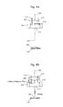
- FIG. 4A is a drawing of illustrating a state in which a tip end of a nozzle is located above a droplet.
- FIG. 4B is a drawing of illustrating a state in which the tip end of the nozzle collides with a membrane filter.
- FIG. 5A is a drawing of explaining the inclination correcting effect of the pipe fixing member by using resilient members.
- FIG. 5B is a comparative drawing of using no resilient members.
- FIG. 6A is a drawing of illustrating a state in which the resilient members are disposed above and beneath the pipe fixing member, and the pipe fixing member is in contact with the lower resilient members by its own weight.
- FIG. 6B is a drawing of explaining the inclination correcting effect by the lower resilient members of the pipe fixing member.
- FIG. 6C is a drawing of illustrating a state in which the resilient members are disposed above and beneath the pipe fixing member, and the pipe fixing member is moved upward.
- FIG. 6D is a drawing of explaining the inclination correcting effect by the upper resilient members of the pipe fixing member.
- FIG. 7A is a drawing of a configuration example of detecting a position and a inclination state of the pipe fixing member.
- FIG. 7B is a drawing of a configuration example of detecting a position and a inclination state of the pipe fixing member.
- FIG. 7C is a drawing of a configuration example of detecting a position and a inclination state of the pipe fixing member.
- FIG. 7D is a drawing of a configuration example of detecting a position and a inclination state of the pipe fixing member.
- FIG. 7E is a drawing of a configuration example of detecting a position and a inclination state of the pipe fixing member.
- FIG. 8 is a drawing of explaining of a liquid suction device capable of microbial measurement.
- FIG. 9 is a flow chart of illustrating steps of liquid suction.
- FIG. 10 is a drawing of illustrating a display screen of an input output unit.
- FIG. 11A is a drawing of explaining a problem caused in the case without employing the present invention.
- FIG. 11B is a drawing of explaining a problem caused in the case without employing the present invention.
- FIG. 11C is a drawing of explaining a problem caused in the case without employing the present invention.
- the liquid suction device is represented as a rectangular parallelepiped with the size of 30 cm depth ⁇ 40 cm width ⁇ 40 cm height.
- the fundamental configuration of the liquid suction device includes the arm 101 movable in the X-Y-Z directions, the pipe 102 , the pipe fixing member 103 to which the pipe 102 is fixed, the pump 104 connected to a rear end of the pipe 102 , the moving mechanism 115 for driving the arm 101 , and the inclination correction mechanism for correcting the inclination when the pipe fixing member 103 is inclined relative to the arm 101 .
- the moving mechanism 115 and the pump 104 are controlled by the controller 105 .
- the liquid suction device further includes the plural sample containers 106 , 107 , 108 and the sample container stand 109 .
- the sample container 106 illustrated in the drawing has the bottom surface made of the membrane filter 110 .
- the rail base 111 is fixed to the arm 101 , and the plural rails 112 are fixed to the rail base 111 .
- the plural rails are disposed in parallel to each other.
- FIG. 2A is an exploded view of the pipe fixing member 103 and the rail base 111 .
- FIG. 2B is a drawing of illustrating a state in which the pipe fixing member 103 and the rail base 111 are assembled.
- the pipe fixing member 103 is provided with the through holes 113 vertically extending through the pipe fixing member 103 , and the rails 112 are inserted in the through holes 113 as illustrated in FIG. 2B .
- the pipe fixing member 103 is vertically movable along the rails 112 , as indicated by the vertical arrow in the FIG. 2B .
- the pipe fixing member 103 is in contact with the resilient members 114 disposed on the rail base 111 by its own weight, but is not combined to these resilient members 114 .
- FIG. 3A is a schematic plan view of illustrating one example of the pipe fixing member
- FIG. 3B is a schematic plan view of illustrating one example of the rail base.
- each of the resilient members 114 disposed on the rail base 111 is placed at each corner outside a rectangle defined by the four rails 112 .
- the hole 116 is formed at the center of the rail base 111 , and the pipe 102 is inserted through this hole 106 .
- FIG. 3B is a schematic plan view of illustrating one example of the pipe fixing member
- FIG. 3B is a schematic plan view of illustrating one example of the rail base.
- the four rails 112 are inserted in the respective four through holes 113 in the pipe fixing member 103 , and the pipe fixing member 103 comes in contact with the resilient members 114 in such a manner that the pipe fixing member 103 covers these resilient members 114 at the four corner by its own weight.
- the pipe 102 is fixed at the center of the pipe fixing member 103 .
- the pipe 102 of the present embodiment is formed of a cylindrical glass capillary (manufactured by GL Sciences Inc.) having the length of 2 m, the inner diameter of 0.530 mm and the outer diameter of 0.660 mm.
- One end of the pipe 102 is connected to the pump 104 , and the pipe 102 is fixed to the pipe fixing member 103 at a position of 4 cm from the other end of the pipe.
- the 4 cm portion from the pipe opening end to the pipe fixing member 103 functions as a nozzle and the pipe opening end functions as the nozzle end. Integration of the nozzle with the pipe simplifies the configuration of the nozzle and the pipe, and elimination of the connected face between the nozzle and the pipe stabilizes the liquid suction speed and prevents contamination from the connected face between the nozzle and the pipe.
- the arm 101 can move 20 cm in the X-Y (plan) direction and 20 cm in the Z (vertical) direction.
- the pipe fixing member 103 is formed in a rectangular parallelepiped of polypropylene material with the weight of 3 g and the size of 3 cm depth ⁇ 1.5 cm width ⁇ 0.5 cm height.
- Each of the four through holes 113 formed in the pipe fixing member 103 is a cylindrical hole with the diameter of 0.3 cm.
- the four rails 112 are disposed on the arm 101 , and made of aluminum material, and each of them has the diameter of 0.28 cm.
- the pipe fixing member 103 is provided with the rails 112 inserted through the through holes 113 , and the pipe fixing member 103 is restrained by the rails 112 so as to be movable relative to the arm 101 .
- the membrane filter 110 used for the bottom surface of the container was an membrane filter prepared by cutting an MF-Millipore membrane filter (manufactured by Millipore Corporation) with the pore size of 0.45 ⁇ m, the thickness of 150 ⁇ m and the porosity rate of 79%, or a Mitex membrane filter (manufactured by Millipore Corporation) with the pore size of 10 ⁇ m, and a polycarbonate filter (manufactured by Millipore Corporation) with the pore size of 0.3 ⁇ m and the thickness of 7 ⁇ m into a circular shape with the diameter of 0.5 cm, respectively.
- MF-Millipore membrane filter manufactured by Millipore Corporation
- a Mitex membrane filter manufactured by Millipore Corporation
- a polycarbonate filter manufactured by Millipore Corporation
- a polypropylene tube SARSTEDT, 55.535
- a polystyrene tube SARSTEDT, 657.462
- the resilient members 114 may be magnets, and if magnets are used as the resilient members 114 , the magnets disposed on the surface of the pipe fixing member 103 opposing the resilient members 114 are configured to have the same pole as those of the magnets disposed on the resilient members 114 .
- FIG. 4A and FIG. 4B are drawings of illustrating the effect generated by the movement of the pipe fixing member along the rails.
- the arm 101 is located at any height, and the pipe opening end (nozzle tip end) 201 is in contact with nowhere, and is positioned above the droplet 202 on the membrane filter 110 .
- the pipe fixing member 103 lies on the resilient members 114 and moves downward along with the arm 101 .
- the aim 101 is continuously moved downward and when the nozzle tip end 201 collides with the membrane filter 110 , the pipe fixing member 103 moves upward along the rails 112 by the distance where the arm 101 is moved downward after the collision.
- This movement prevents the nozzle tip end 201 and the membrane filter 110 from being damaged even if the nozzle tip end 201 collides with the membrane filter 110 , thereby securely bringing the nozzle tip end 201 into contact with the membrane filter 110 (collision relaxation effect).
- the droplet 202 on the membrane filter 110 is sucked. Since the nozzle tip end 201 and the membrane filter 110 are in contact with each other, there is no clearance between the nozzle tip end 201 and the membrane filter 110 , thereby attaining the efficient suction of the droplet 202 .
- the nozzle tip end 201 preferably has a shape other than a flat shape relative to the membrane filter 110 . If the nozzle tip end 201 has a flat shape parallel to the surface of the membrane filter, the nozzle tip end 201 is buried in the membrane filter 110 after the contact of the nozzle tip end 201 with the membrane filter 110 , so that it is difficult to suck the droplet 202 .
- the nozzle tip end having an obliquely cut shape can be prevented from being buried in the membrane filter, so as to suck the droplet.
- the collision relaxation effect is generated by the movement of the pipe fixing member 103 along the rails 112 .
- the pipe fixing member 103 is necessary to be movable vertically along the rails 112 , but if the pipe fixing member 103 is inclined relative to the arm 101 , friction occurs between the through holes 113 of the pipe fixing member 103 and the rails 112 , which hinders the vertical movement of the pipe fixing member 103 .
- the through holes 113 and the rails 112 As a method of preventing the inclination of the pipe fixing member 103 , it can be considered to configure the through holes 113 and the rails 112 to have diameters in the approximately same size, but in such a configuration, even slight inclination of the pipe fixing member 103 causes friction between the inner surfaces of the through holes 113 and the outer surfaces of the rails 112 , which hinders the vertical movement of the pipe fixing member 103 .
- the inclination of the pipe fixing member 103 affects the positioning accuracy of the nozzle tip end 201 , and when the nozzle tip end 201 is brought into contact with slight amount of the droplet 202 , the nozzle tip end 201 becomes inclined due to the inclination of the pipe fixing member 103 so that the nozzle tip end 201 is deviated from the position, which hinders the contact with the slight amount of the droplet; as a result no droplet is collected through the suction.
- the inclination of the pipe fixing member 103 is caused when the arm 101 moves in the X-Y direction or in the Z direction and/or when the nozzle tip end 201 comes in contact with the bottom surface of the container. In this process, the inclination of the pipe fixing member 103 should be corrected.
- FIG. 5A illustrates the rail base 111 with the resilient members thereon
- FIG. 5B illustrates the rail base 111 without the resilient members thereon.
- Defining the state of the FIG. 4A as the initial state we focused on the inclination starting with this initial state.
- the nozzle tip end 201 is in contact with nowhere, and the arm 101 is located at any X-Y-Z position, and as illustrated in FIG. 3B , the resilient members 114 are disposed outside the rectangle surrounded by the rails and beneath the pipe fixing member 103 .
- the pipe fixing member 103 is in contact with the resilient members 114 by its own weight, and the pipe fixing member 103 is not inclined in this state.
- the inclination correcting effect was evaluated by using the following two methods.
- the inclination correcting effect was evaluated based on the amount of the lateral movement of the arm 101 .
- the pipe was fixed at its portion in the vicinity of the pump 104 , and the arm 101 was moved away from this fixing position in the lateral direction, so as to incline the pipe fixing member 103 and evaluate the distance in which the pipe fixing member 103 was movable vertically.
- the amount of the lateral movement was improved 70%, compared to the case of providing no resilient members 114 .
- the above two results show that the pipe fixing member 103 is vertically movable even if the pipe 102 is bent. Since the degree of freedom for bending the pipe increases, the pipe designing becomes more flexible by the increase of the degree of freedom, thereby realizing the size reduction of the device.
- the increase in amount of the lateral movement indicates the increase in movement amount of the nozzle tip end in the X-Y direction and in the Z direction, thereby significantly reducing probability of causing damage to the various parts at the time of the collision of the nozzle tip end with the bottom surface of the container due to the inclination of the pipe fixing member.
- the number of the rails 112 may be two or less, and in this case, it was found that the pipe fixing member 103 was likely to be inclined and it was difficult to correct the inclination. It is preferable to dispose the respective rails 112 with the equal distance from the center of the rail base 111 and with the equal distance between the rails as well, but these distances are unnecessary to be equal so strictly.
- the installation position of the resilient members 114 It is preferable to set the installation position of the resilient members 114 on or outside the polygon defined by connecting the respective positions of the rails 112 on the rail base 111 ( FIG. 3B ).
- the resilient members 114 are preferably disposed on or outside the rectangle having apexes of the four rails 112 .
- the resilient members 114 may also be disposed at the positions of the respective rails 112 so as to surround these rails. It is preferable that the resilient members 114 are combined to either the pipe fixing member 103 or the rail base 111 , or are combined to neither of them. It was found that, if the resilient members 114 were combined to both the pipe fixing member 103 and the rail base 111 , damage was caused to the nozzle tip end and/or the bottom surface of the container.
- the inclination correcting effect is generated by the contact of the pipe fixing member 103 with the resilient members 114 when the pipe fixing member 103 becomes inclined. As illustrated in FIG. 4B , while the pipe fixing member 103 is apart from the resilient members 114 due to the collision relaxation effect, no inclination effect is generated because the resilient members 114 is out of the contact with the pipe fixing member 103 even if the pipe fixing member 103 becomes inclined.
- the resilient members 301 were additionally provided above the pipe fixing member in the upward movement direction. This configuration will be described with reference to FIG. 6A to FIG. 6D .
- the upper rail base 121 is fixed onto the upper ends of the rails 112 , and the resilient members 301 are provided on the bottom face of this upper rail base.
- the upper resilient members 301 are disposed at the respective plural positions opposite to the respective lower resilient members 114 provided on the rail base 111 .
- the clearance between the rail base 111 and the rail base 121 is set such that the resilient members come in contact with the pipe fixing member 103 at the time of the inclination of the pipe fixing member 103 . In the present embodiment, this clearance was set to be 3 cm.
- the nozzle tip end 201 is in contact with nowhere, the arm 101 is located at any X-Y-Z position, and the pipe fixing member 103 is in contact with the lower resilient members 114 by its own weight.
- the pipe fixing member 103 is out of contact with the upper resilient members 301 above the pipe fixing member 103 in the upward movement direction. If the arm 101 is laterally moved to the left from this state, the upper portion of the pipe 102 from the pipe fixing member 103 is bent to the right. If the arm 101 is further laterally moved to the left, the pipe 102 is bent to the right, and the pipe fixing member 103 is inclined to the right along with this movement. As illustrated in FIG.
- FIG. 6C illustrates the state in which the pipe fixing member 103 is moved upward, and this state indicates when the nozzle tip end 201 comes in contact with the bottom surface of the container or the very moment the nozzle tip end 201 comes apart from the bottom surface of the container.
- the pipe fixing member 103 is in contact with the upper resilient members 301 but is out of contact with the lower resilient members 114 . If the arm 101 is laterally moved to the left in this state, the pipe 102 becomes bent to the right. If the arm 101 is further laterally moved to the left, the pipe 102 becomes bent to the right, and the pipe fixing member 103 becomes inclined rightward along with this movement.
- a faint light detecting apparatus is designed to have an outer body as a dark box for preventing light from entering from outside, so as to realize high sensitivity of the detecting apparatus while preventing external light from being stored in a detecting part such as a photo multiplier in the dark box.
- the door of the dark box cannot be opened every time the state of the pipe fixing member 103 is confirmed.
- the liquid suction device includes the plural conductive resilient members 114 , 301 above and below the pipe fixing member 103 , and the respective resilient members are electrically connected to the controller 105 .
- the pipe fixing member 103 is provided with the conducting layers 401 on the contact faces relative to the resilient members 114 , 301 , and when the resilient members 114 , 301 come in contact with the pipe fixing member 103 , the resilient members in contact with the pipe fixing member are electrically conducted to each other.
- the upper conducting layer and the lower conducting layer of the pipe fixing member 103 are also electrically connected to each other.
- the pipe fixing member 103 becomes inclined, part of the lower resilient members 114 comes in contact with the lower conducting layer of the pipe fixing member 103 , and part of the upper resilient members 114 also comes in contact with the upper conducting layer of the pipe fixing member 103 , these upper and lower resilient members become conducted to each other through the conducting layers thereby detecting the inclination of the pipe fixing member 103 .
- the piezoelectric elements 402 , 403 are provided at the base portions of the respective resilient members 114 , 301 , and when the pipe fixing member 103 becomes inclined to push the resilient members, the piezoelectric elements 402 , 403 detect this pressing force from these resilient members.
- FIG. 7A is a drawing of illustrating that the pipe fixing member 103 is located at the reference position.
- the nozzle tip end 201 is in contact with nowhere, the arm 101 is located at any X-Y-Z position, and the pipe fixing member 103 is in contact with the lower resilient members 114 by its own weight.
- the lower conducting layer 401 on the bottom face of the pipe fixing member 103 is in contact with the resilient members 114 , so that the resilient members 114 are electrically connected. Since the pipe fixing member 103 is not inclined, no pressure greatly exceeding the own weight (pressure at the predetermined value) of the pipe fixing member 103 is applied to the piezoelectric elements 402 disposed at the base portions of the resilient members 114 . If the above electrical connection is detected and the pressure detected by the piezoelectric elements 402 is the predetermined value, the liquid suction device determines that the pipe fixing member 103 is at the reference position.
- FIG. 7B is a drawing of illustrating that the nozzle tip end 201 comes in contact with the bottom surface of the container 404 , and the pipe fixing member 103 is moved upward.
- the pipe fixing member 103 is in contact with none of the resilient members, thus the resilient members are not electrically conducted to each other.
- No pressing force is applied to the piezoelectric elements disposed at the base portions of the resilient members. If there is no conduction and no pressure is detected by the piezoelectric elements, the liquid suction device determines that the pipe fixing member 103 is not inclined and the nozzle tip end 201 comes in contact with the bottom surface of the container.
- FIG. 7C is a drawing of illustrating that the arm 101 is further moved downward after the nozzle tip end 201 comes in contact with the bottom surface of the container 404 , and the pipe fixing member 103 reaches the upper limit of the upward movement.
- the pipe fixing member 103 is in contact with the upper resilient members 301 so that the upper resilient members 301 are electrically conducted to each other. Since the pipe fixing member 103 is not inclined, no pressing force is applied to the piezoelectric elements 403 disposed at the base portions of the resilient members 301 .
- the liquid suction device determines that the pipe fixing member 103 is not inclined, the nozzle tip end 201 is in contact with the bottom surface of the container, and the pipe fixing member 103 reaches the upper limit of the upward movement.
- FIG. 7D is a drawing of illustrating that the pipe fixing member 103 becomes inclined to push part of the lower resilient members 114 , and the resilient members 114 push back the pipe fixing member 103 , but the inclining force is greater than the pushing back force, so that the inclination correcting effect is disable.
- the pipe fixing member 103 is in contact with only the resilient members 114 on the inclination side. At this time, no electrical conduction is made between the resilient members 114 . Since the pipe fixing member 103 is inclined, pressure much greater than the own weight of the pipe fixing member 103 is applied to the piezoelectric elements 402 disposed at the base portions of part of the lower resilient members 114 . If no electrical conduction is made between the resilient members and part of the piezoelectric elements 402 detects pressure at the predetermined value or more, the liquid suction device determines that the resilient members 114 cannot function, and the pipe fixing member 103 is inclined.
- FIG. 7E is a drawing of illustrating that the pipe fixing member 103 becomes inclined to push part of the upper resilient members 301 , and the upper resilient members 301 push back the upper resilient members 301 , but the inclining force exceeds the pushing back force, so that the inclination correcting effect is disable.
- the pipe fixing member 103 is in contact with only the upper resilient members 301 on the opposite side to the inclination side. At this time, no electrical conduction is made between the resilient members 301 . Meanwhile, pressure at the specified value or more is applied to the part of the upper piezoelectric elements 403 . If no electrical conduction is made and the part of the upper piezoelectric elements detects great pressure, the liquid suction device determines that the resilient members 301 cannot function and the pipe fixing member 103 is inclined.
- metal springs were used for the resilient members, and aluminum thin films were used for the conducting layers 401 .
- Metal material or conductive polymer films may also be used for the resilient members and the conducting layers 401 as far as they are electrically conductive.
- the pipe adjustment unit 801 includes a rotor, and winds the pipe 102 around the rotor, and adjusts the pipe length between the pipe adjustment unit 801 and the pipe fixing member 103 by rotating this rotor, thereby correcting the inclination of the pipe fixing member 103 . Even if the pipe becomes inclined at the angle of 38° or more as illustrated in FIG. 5A , this pipe adjustment can correct the inclination by adjusting the pipe length.
- the liquid suction operation is started (S 501 ).
- the liquid suction device confirms the conduction between the lower resilient members 114 (S 502 ). If no conduction is confirmed therebetween or electric conduction is confirmed between the upper resilient members 301 , it is determined that the pipe fixing member 103 is inclined or is not at the reference position, thus the pipe adjustment unit is operated to correct the inclination of the pipe fixing member 103 (S 503 ). If the conduction is confirmed between the lower resilient members 114 , the detected pressure on the piezoelectric elements 402 disposed at the base portions of the lower resilient members is confirmed (S 504 ).
- the pipe adjustment unit is operated to correct the inclination of the pipe fixing member 103 . If no pressure of the predetermined value or more is detected, it is determined that the pipe fixing member 103 is at the normal position ( FIG. 7A ) (S 505 ).
- the liquid suction device selects the moving operation of the arm 101 in the X-Y direction or in the Z direction (S 506 ). If the arm 101 is moved in the X-Y axial plane direction (S 507 ), the position and the inclination of the pipe fixing member 103 are confirmed again after the moving operation of the arm 101 is completed (S 508 ).
- the arm 101 is moved downward (S 509 ), and the conduction between the resilient members is monitored (S 510 ). If the conduction between the lower resilient members 114 is detected (S 511 ), it is determined that the nozzle tip end 201 is out of contact with the bottom surface of the container 404 , and the arm 101 is continued to be moved downward. If the upper resilient members 301 are conducted to each other, and the pipe fixing member 103 is determined to be at the upper limit of the upward movement (S 512 ), or if no conduction is detected between the lower resilient members 114 and between the upper resilient members 301 (S 510 ), the pressure on the piezoelectric elements 402 is confirmed (S 513 ).
- the pipe fixing member 103 is moved upward (S 514 ), so that the downward movement of the arm 101 is stopped. Thereafter, the liquid is sucked from the nozzle tip end 201 (S 515 ), the arm 101 is moved upward (S 516 ), and the movement of the arm 101 is selected (S 517 ) or the liquid suction operation is completed (S 518 ).
- the liquid discharging operation may be carried out in accordance with the flow of FIG. 9 , and the discharge operation may be carried out instead of the suction operation in Step S 515 .
- the pipe fixing member may be configured to always monitor the inclination state of the pipe fixing member, store monitored data on a storage unit and record data regarding the liquid suction operation accomplished normally from start to finish.
- the monitored data may be used as the certificate that a dispensing operation in a human blood examination has been performed and completed appropriately in the case of incorporating the present invention in an examination apparatus in the medical field, for example. This configuration enables it possible to quickly find out an abnormal step in the dispensing operation if any abnormality is found in the monitored data, so as to prevent important samples from being lost and secure parts replacement.
- the faint luminous reaction was caused in ATP (Adenosine triphosphate) molecules derived from Escherichia coli with firefly luciferase and luciferin in a dark box so as to detect luminescence, and the detected luminescence was converted into ATP amount as the Escherichia coli detection sensitivity, and the comparison of the Escherichia coli detection sensitivity was made between both the cases.
- ATP Addenosine triphosphate
- FIG. 8 is a schematic diagram of an analyzer used in the present embodiment.
- a sample container having a bottom surface of a membrane filter can be installed in the liquid suction device.
- the liquid suction device includes the suction unit 802 , the waste fluid unit 803 , the microbial dissolution solution supply unit 804 for storing the microbial dissolution solution 805 , the detection unit 806 , the luminescence reagent reservoir 807 for storing the luminescence reagent 808 and these components are housed in the dark box 809 .
- the liquid suction device is operated through the input output unit 810 provided on the outside of the dark box 809 .
- a measurer cannot open the dark box 809 from the installation of the sample container 106 until the completion of the detection of the faint luminous reaction, and cannot visually confirm the position and the inclination state of the nozzle tip end 201 in the dark box 809 .
- FIG. 10 is a drawing of illustrating the display screen of the input output unit 810 .
- This input output unit displays the position of the nozzle tip end and the inclination state of the pipe fixing member in accordance with the operation procedure as illustrated in FIG. 9 .
- the step monitoring display 608 displays the current step of the nozzle operation.
- the nozzle tip end 201 was moved downward to come in contact with the membrane filter 110 , so as to suck the microbial dissolution solution remained on the membrane filter 110 into the pipe 102 , and discharged the sucked microbial dissolution solution into the luminescence reagent 808 (luminescence reagent of 200 ⁇ L, attached to the Lucifell HS Set) in the luminescence reagent reservoir 807 disposed on the detection unit 806 with the nozzle tip end 201 in contact with the bottom surface of the luminescence reagent reservoir 807 .
- the luminescence reagent 808 luminescence reagent of 200 ⁇ L, attached to the Lucifell HS Set
- the detection unit 806 Since the bottom surface of the luminescence reagent reservoir 807 was nearest to the detection unit 806 , and discharging the sucked microbial dissolution solution 805 at this position enables the most efficient detection of the generated luminescence by the detection unit 806 . In the case of discharging the sucked microbial dissolution solution with the nozzle tip end 201 out of contact with the bottom surface, the detection sensitivity was decreased.
- the input output unit 810 further includes the measurement start button 607 and the step monitoring display 608 for informing the current step. Meanwhile, in the case without the liquid suction device of the present invention, only luminous reaction spectra were acquired.
- the result in the case of employing the present invention was 1.36 amol ATP per Escherichia coli cell on average, along with SD 0.01 amol ATP, and C.V. 1%.
- the result in the case without employing the present invention was 0.95 amol ATP per Escherichia coli cell on average, along with SD 0.34 amol ATP, C.V. 35.4%; therefore, in the case of the present invention, the average value, SD and C.V. were all improved.
Abstract
Description
- Patent Literature 1: JP 2000-55925 A
- Patent Literature 2: JP 11-271322 A (1999)
- Patent Literature 3: JP 2005-172764 A
- Patent Literature 4: JP 2000-88864 A
- Patent Literature 5: JP 2007-139704 A
(2) The relative displacement between the pipe fixing member and the arm is accomplished by providing three or more rails parallel to each other and extending upward from the arm, and inserting the rails through the through holes formed in the pipe fixing member so that the pipe fixing member can move along the rails. The inclination correction of the nozzle is accomplished by providing resilient members on or outside a polygon defined by connecting the respective positions of the rails on the arm. The resilient members are not combined with the pipe fixing member. If the pipe fixing member becomes inclined relative to the aim on the rails, the pipe fixing member pushes the resilient members, and then the resilient members pushes back the pipe fixing member, thereby correcting the inclination of the nozzle. This configuration can bring the pipe opening end (nozzle tip end) into contact with the bottom surface of the container, so as to collect the solution.
(3) The resilient members are provided in every direction in which the pipe fixing member is relatively movable, and if the pipe fixing member becomes inclined while the pipe fixing member is located on either side of the movable direction relative to the middle of the rails, the pipe fixing member pushes the resilient members disposed on the either side of the movable direction, and then the resilient members push back the pipe fixing member so as to correct the inclination.
(4) The resilient members are configured to be conductive, and the pipe fixing member is provided with a conducting layer on its surface to be in contact with the resilient members. In this case, the plural resilient members are electrically conducted to each other through the contact between the resilient members and the pipe fixing member, and the inclination of the pipe fixing member is determined based on whether or not the resilient members are conducted to each other.
(5) The piezoelectric elements are provided at the base portions of the resilient members. In this case, if the pipe fixing member is inclined and pushes the resilient members, the piezoelectric elements detects the pressing force from the resilient members so as to detect the inclination of the pipe fixing member.
(6) It may be configured that the inclination of the pipe fixing member is detected based on whether or not the resilient members are electrically conducted to each other, or whether or not the pushing force is detected by the piezoelectric elements, and if the inclination of the pipe fixing member at a predetermined value is detected, the pipe adjustment unit corrects the inclination of the pipe fixing member.
(7) The pipe adjustment unit is disposed between the pipe fixing member and the pump. The pipe adjustment unit includes a rotor around which the pipe is wound, and adjusts the length of the pipe between the pipe adjustment unit and the pipe fixing member, so as to correct the inclination of the pipe fixing member.
(8) The liquid suction device moves the arm in the X-Y direction so as to move the pipe opening end above the sample container, and moves the arm in the Z direction so as to bring the pipe opening end in contact with the bottom surface of the sample container. At the moment of the contact, the pipe fixing member combined with the pipe moves along the rails combined with the arm, and then the liquid suction device sucks the liquid from the pipe opening end into the pipe.
(9) Before moving the arm in the X-Y-Z directions, it is confirmed whether or not the conduction is made between the resilient members, and it is determined that the pipe fixing member is located at the normal position if the conduction between the resilient members is detected; the pipe fixing member is located at the abnormal position if no conduction between the resilient members is detected. In the case of the abnormal position, the pipe adjustment unit adjusts the length of the pipe so as to correct the pipe fixing member at the normal position. If the pipe fixing member is located at the normal position, the arm is moved in the X-Y direction or in the Z direction. During the movement of the arm in the Z direction, the conduction between the resilient members is monitored, and it is determined that the pipe opening end is not contact with the bottom surface of the container while the conduction between the resilient members is being detected, so that the arm is continued to be moved in the Z direction. At the moment when no conduction between the resilient members is detected, it is determined that the pipe opening end comes in contact with the bottom surface of the container, and the movement of the arm in the height direction is stopped. Thereafter, the liquid is sucked from the pipe opening end.
(10) The resilient members are disposed not only beneath but also above the pipe fixing member. It is determined that the pipe fixing member is located at the normal position if the lower resilient members are conducted to each other, and it is determine that the pipe fixing member reaches the upper limit of the vertical movement if the upper resilient members are conducted to each other. If the conduction is made between the upper resilient members and the lower resilient members, it is determined that the pipe fixing member is inclined, and then the pipe adjustment adjusts the length of the pipe, so as to correct the inclination of the pipe fixing member.
(11) If the piezoelectric elements disposed at the base portions of the resilient members detect pressing force at the predetermined value or more, it is determined that the pipe fixing member is inclined, and then the pipe adjustment unit adjusts the length of the pipe, so as to correct the inclination of the pipe fixing member.
(12) The resilient members may be formed of springs, rubber, sponge or magnets. If the resilient members are formed of magnets, a portion of the pipe fixing member opposing the resilient members is configured to include magnets with the same pole as those of the magnets of the resilient members. The portions opposing each other between the resilient members and the pipe fixing member and between the rails may be configured to include magnets having the same pole, alternatively.
- 101 Arm
- 102 Pipe
- 103 Pipe fixing member
- 104 Pump
- 105 Controller
- 106 to 108 Sample containers
- 109 Sample container stand
- 110 Membrane filter
- 111 Rail base
- 112 Rails
- 113 Through hole
- 114 Resilient member
- 121 Upper rail base
- 201 Nozzle tip end
- 202 Droplet
- 301 Resilient member
- 401 Conducting layer
- 402 Piezoelectric element
- 403 Piezoelectric element
- 404 Container bottom surface
- 602 Pipe inclination alert display
- 603 Pipe-adjustment-unit in operation display
- 604 Pipe-fixing-member at normal position display
- 605 Container-bottom-surface in contact display
- 606 luminescence monitoring display
- 607 Measurement start button
- 608 Step monitoring display
Claims (17)
Applications Claiming Priority (3)
| Application Number | Priority Date | Filing Date | Title |
|---|---|---|---|
| JP2010-039247 | 2010-02-24 | ||
| JP2010039247A JP5514582B2 (en) | 2010-02-24 | 2010-02-24 | Liquid suction device |
| PCT/JP2010/073076 WO2011104986A1 (en) | 2010-02-24 | 2010-12-22 | Liquid suction device |
Publications (2)
| Publication Number | Publication Date |
|---|---|
| US20120321520A1 US20120321520A1 (en) | 2012-12-20 |
| US9091671B2 true US9091671B2 (en) | 2015-07-28 |
Family
ID=44506421
Family Applications (1)
| Application Number | Title | Priority Date | Filing Date |
|---|---|---|---|
| US13/580,674 Expired - Fee Related US9091671B2 (en) | 2010-02-24 | 2010-12-22 | Liquid suction device |
Country Status (5)
| Country | Link |
|---|---|
| US (1) | US9091671B2 (en) |
| EP (1) | EP2541256A1 (en) |
| JP (1) | JP5514582B2 (en) |
| SG (1) | SG183448A1 (en) |
| WO (1) | WO2011104986A1 (en) |
Families Citing this family (11)
| Publication number | Priority date | Publication date | Assignee | Title |
|---|---|---|---|---|
| JP5850625B2 (en) * | 2011-03-02 | 2016-02-03 | シスメックス株式会社 | Analysis apparatus and position confirmation method |
| US9529008B2 (en) | 2011-03-03 | 2016-12-27 | Life Technologies Corporation | Sampling probes, systems, apparatuses, and methods |
| JP5752545B2 (en) * | 2011-09-22 | 2015-07-22 | 株式会社日立ハイテクノロジーズ | Automatic analyzer |
| JP5597731B2 (en) * | 2013-01-04 | 2014-10-01 | あおい精機株式会社 | Inspection pretreatment equipment |
| US9945883B2 (en) * | 2014-04-08 | 2018-04-17 | Life Technologies Corporation | Pipette system |
| JP6832418B2 (en) * | 2016-07-21 | 2021-02-24 | シーメンス・ヘルスケア・ダイアグノスティックス・インコーポレーテッドSiemens Healthcare Diagnostics Inc. | Test system alignment automation |
| JP6854292B2 (en) * | 2016-09-21 | 2021-04-07 | 株式会社日立ハイテク | Automatic analyzer |
| CN107020166A (en) * | 2017-04-07 | 2017-08-08 | 周肇梅 | A kind of use for laboratory liquid getting device |
| DE102019119414B3 (en) * | 2019-07-17 | 2020-06-18 | Pilz Gmbh & Co. Kg | Manipulation detection system for a filler neck of a bottling plant and method for detecting manipulation on a filler neck of a bottling plant |
| KR20210033197A (en) * | 2019-09-18 | 2021-03-26 | 엘지전자 주식회사 | Robot and method for calculating level of liquid in the liquid container |
| JP2024025565A (en) * | 2022-08-12 | 2024-02-26 | アークレイ株式会社 | nozzle structure |
Citations (24)
| Publication number | Priority date | Publication date | Assignee | Title |
|---|---|---|---|---|
| JPS59176946A (en) | 1983-03-26 | 1984-10-06 | Nec Corp | Communication system |
| JPH03183958A (en) | 1989-12-13 | 1991-08-09 | Shimadzu Corp | Sampling device |
| US5055263A (en) * | 1988-01-14 | 1991-10-08 | Cyberlab, Inc. | Automated pipetting system |
| US5213766A (en) * | 1991-04-30 | 1993-05-25 | Apogee Designs, Ltd. | Liquid collecting apparatus for sample testing |
| US5474744A (en) | 1993-10-28 | 1995-12-12 | Hoffmann-La Roche Inc. | Automatic pipetting device with cleaning mechanism |
| JP2554202B2 (en) | 1990-11-28 | 1996-11-13 | 株式会社日立製作所 | Sample dispenser |
| JPH0921815A (en) | 1995-07-04 | 1997-01-21 | Toshiba Corp | Automatic analyzing device |
| JPH11271322A (en) | 1998-03-24 | 1999-10-08 | Olympus Optical Co Ltd | Liquid suction method |
| JP2000055925A (en) | 1998-08-13 | 2000-02-25 | Jeol Ltd | Safety device of pipette nozzle in analyzing device |
| JP2000088864A (en) | 1998-09-17 | 2000-03-31 | Jasco Corp | Movable limiter for autosampler and nozzle therefor |
| US20010019845A1 (en) * | 1998-08-07 | 2001-09-06 | Klaus Bienert | Metering head for parallel processing of a plurality of fluid samples |
| JP2001321648A (en) | 2000-05-17 | 2001-11-20 | Nippon Techno Kk | Method for preparing stable dispersion liquid consisting of water and oil |
| US20010055545A1 (en) * | 2000-06-22 | 2001-12-27 | Shimadzu Corporation | Drainage system |
| US20020146353A1 (en) * | 2000-02-01 | 2002-10-10 | Incyte Pharmaceuticals | Multichannel pipette head |
| JP2005172764A (en) | 2003-12-15 | 2005-06-30 | Canon Inc | Dispensing device |
| US20050169808A1 (en) * | 2001-06-27 | 2005-08-04 | The Regents Of The University Of California | Capillary pins for high-efficiency microarray printing device |
| US20060034732A1 (en) * | 2004-08-03 | 2006-02-16 | Bargh Adrian N | Pipetting device |
| JP2007139704A (en) | 2005-11-22 | 2007-06-07 | Sugino Mach Ltd | Regulator for reference height position of nozzle tip, and sampler |
| US20090068063A1 (en) * | 2007-08-29 | 2009-03-12 | Chiba Hideyasu | Automatic analyzer |
| JP2009134137A (en) | 2007-11-30 | 2009-06-18 | Canon Inc | Thin image display |
| US20090272202A1 (en) * | 2008-05-05 | 2009-11-05 | Institute Of Occupational Safety And Health | Personal nanoparticle sampler |
| US7988934B2 (en) * | 2006-04-28 | 2011-08-02 | Tecan Trading Ag | Carrier for positioning objects in relation to laboratory articles |
| US8283181B2 (en) * | 2001-06-27 | 2012-10-09 | The Regents Of The University Of California | Capillary pins for high-efficiency microarray printing device |
| US8679421B2 (en) * | 2009-09-11 | 2014-03-25 | Hitachi High-Technologies Corporation | Dispensing device and analyzer |
Family Cites Families (1)
| Publication number | Priority date | Publication date | Assignee | Title |
|---|---|---|---|---|
| JPS59176946U (en) * | 1983-05-13 | 1984-11-27 | 株式会社日立製作所 | Collision prevention mechanism for sampling nozzle |
-
2010
- 2010-02-24 JP JP2010039247A patent/JP5514582B2/en not_active Expired - Fee Related
- 2010-12-22 EP EP10846649A patent/EP2541256A1/en not_active Withdrawn
- 2010-12-22 SG SG2012062212A patent/SG183448A1/en unknown
- 2010-12-22 WO PCT/JP2010/073076 patent/WO2011104986A1/en active Application Filing
- 2010-12-22 US US13/580,674 patent/US9091671B2/en not_active Expired - Fee Related
Patent Citations (26)
| Publication number | Priority date | Publication date | Assignee | Title |
|---|---|---|---|---|
| JPS59176946A (en) | 1983-03-26 | 1984-10-06 | Nec Corp | Communication system |
| US5055263A (en) * | 1988-01-14 | 1991-10-08 | Cyberlab, Inc. | Automated pipetting system |
| JPH03183958A (en) | 1989-12-13 | 1991-08-09 | Shimadzu Corp | Sampling device |
| JP2554202B2 (en) | 1990-11-28 | 1996-11-13 | 株式会社日立製作所 | Sample dispenser |
| US5213766A (en) * | 1991-04-30 | 1993-05-25 | Apogee Designs, Ltd. | Liquid collecting apparatus for sample testing |
| US5474744A (en) | 1993-10-28 | 1995-12-12 | Hoffmann-La Roche Inc. | Automatic pipetting device with cleaning mechanism |
| JPH0921815A (en) | 1995-07-04 | 1997-01-21 | Toshiba Corp | Automatic analyzing device |
| JP3481732B2 (en) | 1995-07-04 | 2003-12-22 | 株式会社東芝 | Automatic analyzer |
| JPH11271322A (en) | 1998-03-24 | 1999-10-08 | Olympus Optical Co Ltd | Liquid suction method |
| US20010019845A1 (en) * | 1998-08-07 | 2001-09-06 | Klaus Bienert | Metering head for parallel processing of a plurality of fluid samples |
| JP2000055925A (en) | 1998-08-13 | 2000-02-25 | Jeol Ltd | Safety device of pipette nozzle in analyzing device |
| JP2000088864A (en) | 1998-09-17 | 2000-03-31 | Jasco Corp | Movable limiter for autosampler and nozzle therefor |
| US20020146353A1 (en) * | 2000-02-01 | 2002-10-10 | Incyte Pharmaceuticals | Multichannel pipette head |
| JP2001321648A (en) | 2000-05-17 | 2001-11-20 | Nippon Techno Kk | Method for preparing stable dispersion liquid consisting of water and oil |
| US20010055545A1 (en) * | 2000-06-22 | 2001-12-27 | Shimadzu Corporation | Drainage system |
| US20050169808A1 (en) * | 2001-06-27 | 2005-08-04 | The Regents Of The University Of California | Capillary pins for high-efficiency microarray printing device |
| US8283181B2 (en) * | 2001-06-27 | 2012-10-09 | The Regents Of The University Of California | Capillary pins for high-efficiency microarray printing device |
| JP2005172764A (en) | 2003-12-15 | 2005-06-30 | Canon Inc | Dispensing device |
| US20060034732A1 (en) * | 2004-08-03 | 2006-02-16 | Bargh Adrian N | Pipetting device |
| JP2007139704A (en) | 2005-11-22 | 2007-06-07 | Sugino Mach Ltd | Regulator for reference height position of nozzle tip, and sampler |
| US7988934B2 (en) * | 2006-04-28 | 2011-08-02 | Tecan Trading Ag | Carrier for positioning objects in relation to laboratory articles |
| US20090068063A1 (en) * | 2007-08-29 | 2009-03-12 | Chiba Hideyasu | Automatic analyzer |
| US8182745B2 (en) * | 2007-08-29 | 2012-05-22 | Hitachi High-Technologies Corporation | Automatic analyzer |
| JP2009134137A (en) | 2007-11-30 | 2009-06-18 | Canon Inc | Thin image display |
| US20090272202A1 (en) * | 2008-05-05 | 2009-11-05 | Institute Of Occupational Safety And Health | Personal nanoparticle sampler |
| US8679421B2 (en) * | 2009-09-11 | 2014-03-25 | Hitachi High-Technologies Corporation | Dispensing device and analyzer |
Non-Patent Citations (1)
| Title |
|---|
| Office Action of Singapore Appln. No. 201206221-2 dated May 8, 2013 in English. |
Also Published As
| Publication number | Publication date |
|---|---|
| WO2011104986A1 (en) | 2011-09-01 |
| JP5514582B2 (en) | 2014-06-04 |
| EP2541256A1 (en) | 2013-01-02 |
| SG183448A1 (en) | 2012-09-27 |
| US20120321520A1 (en) | 2012-12-20 |
| JP2011174818A (en) | 2011-09-08 |
Similar Documents
| Publication | Publication Date | Title |
|---|---|---|
| US9091671B2 (en) | Liquid suction device | |
| US10613109B2 (en) | Dispensing apparatus | |
| RU2718086C2 (en) | Automated method and system for producing and preparing a sample of a microorganism both for identification and for tests for antibiotic sensitivity | |
| US8580210B2 (en) | Sample aspirating apparatus and sample analyzer | |
| US8698644B2 (en) | Sample processing apparatus, sample container transporting apparatus, sample processing method and sample container transporting method | |
| US20100124518A1 (en) | Transporting apparatus and specimen analyzing apparatus | |
| US9562920B2 (en) | Automated analyzer with cover detection | |
| US20180147577A1 (en) | Tip rack, sample processing apparatus, rack body, and method of attaching nozzle tip | |
| WO2019198493A1 (en) | Electrolyte analyzing device | |
| JP2015175707A (en) | Dispenser and analyzer including the same | |
| EP2404154B1 (en) | Particle characterization | |
| US20120309099A1 (en) | Automatic analyzing device | |
| US20150160252A1 (en) | Method and apparatus for detecting position of liquid surface, liquid supply apparatus, and analyzing system | |
| JP7042728B2 (en) | Pipette device and pipette device positioning system | |
| JP6737285B2 (en) | Inspection kit, liquid delivery method and inspection device using inspection kit | |
| US9114970B2 (en) | Dispensing device and nucleic acid analyzer | |
| US10006849B2 (en) | Particle analyzer | |
| US20150177121A1 (en) | Sample identification sorting apparatus and sample identification sorting method | |
| US11834642B2 (en) | Collection method for fine particles and collection system | |
| US20230264185A1 (en) | Pipette tip and pipette system for capillary blood collection | |
| JP6338898B2 (en) | Automatic analyzer | |
| US10151672B2 (en) | Device and a method for managing a sample to be analyzed and a solid sample carrier and liquid sample carrier | |
| JP5105221B2 (en) | Micro bubble tester | |
| TW202310927A (en) | Dispensing apparatus and dispensing method | |
| US20150139867A1 (en) | Liquid measuring unit and liquid supplying apparatus |
Legal Events
| Date | Code | Title | Description |
|---|---|---|---|
| AS | Assignment |
Owner name: HITACHI PLANT TECHNOLOGIES, LTD., JAPAN Free format text: ASSIGNMENT OF ASSIGNORS INTEREST;ASSIGNORS:OKANOJO, MASAHIRO;NODA, HIDEYUKI;REEL/FRAME:028833/0229 Effective date: 20120719 |
|
| AS | Assignment |
Owner name: HITACHI, LTD., JAPAN Free format text: MERGER;ASSIGNOR:HITACHI PLANT TECHNOLOGIES, LTD;REEL/FRAME:031938/0878 Effective date: 20130401 |
|
| STCF | Information on status: patent grant |
Free format text: PATENTED CASE |
|
| FEPP | Fee payment procedure |
Free format text: MAINTENANCE FEE REMINDER MAILED (ORIGINAL EVENT CODE: REM.); ENTITY STATUS OF PATENT OWNER: LARGE ENTITY |
|
| LAPS | Lapse for failure to pay maintenance fees |
Free format text: PATENT EXPIRED FOR FAILURE TO PAY MAINTENANCE FEES (ORIGINAL EVENT CODE: EXP.); ENTITY STATUS OF PATENT OWNER: LARGE ENTITY |
|
| STCH | Information on status: patent discontinuation |
Free format text: PATENT EXPIRED DUE TO NONPAYMENT OF MAINTENANCE FEES UNDER 37 CFR 1.362 |
|
| FP | Expired due to failure to pay maintenance fee |
Effective date: 20190728 |