US9092762B2 - Medical device maintenance system - Google Patents
Medical device maintenance system Download PDFInfo
- Publication number
- US9092762B2 US9092762B2 US13/440,571 US201213440571A US9092762B2 US 9092762 B2 US9092762 B2 US 9092762B2 US 201213440571 A US201213440571 A US 201213440571A US 9092762 B2 US9092762 B2 US 9092762B2
- Authority
- US
- United States
- Prior art keywords
- medical devices
- maintenance
- list
- medical
- devices
- Prior art date
- Legal status (The legal status is an assumption and is not a legal conclusion. Google has not performed a legal analysis and makes no representation as to the accuracy of the status listed.)
- Active, expires
Links
Images


Classifications
-
- G—PHYSICS
- G06—COMPUTING; CALCULATING OR COUNTING
- G06Q—INFORMATION AND COMMUNICATION TECHNOLOGY [ICT] SPECIALLY ADAPTED FOR ADMINISTRATIVE, COMMERCIAL, FINANCIAL, MANAGERIAL OR SUPERVISORY PURPOSES; SYSTEMS OR METHODS SPECIALLY ADAPTED FOR ADMINISTRATIVE, COMMERCIAL, FINANCIAL, MANAGERIAL OR SUPERVISORY PURPOSES, NOT OTHERWISE PROVIDED FOR
- G06Q10/00—Administration; Management
- G06Q10/20—Administration of product repair or maintenance
-
- G06F19/327—
-
- G06F19/3412—
-
- G—PHYSICS
- G06—COMPUTING; CALCULATING OR COUNTING
- G06F—ELECTRIC DIGITAL DATA PROCESSING
- G06F3/00—Input arrangements for transferring data to be processed into a form capable of being handled by the computer; Output arrangements for transferring data from processing unit to output unit, e.g. interface arrangements
- G06F3/01—Input arrangements or combined input and output arrangements for interaction between user and computer
- G06F3/048—Interaction techniques based on graphical user interfaces [GUI]
- G06F3/0481—Interaction techniques based on graphical user interfaces [GUI] based on specific properties of the displayed interaction object or a metaphor-based environment, e.g. interaction with desktop elements like windows or icons, or assisted by a cursor's changing behaviour or appearance
- G06F3/0482—Interaction with lists of selectable items, e.g. menus
-
- G—PHYSICS
- G06—COMPUTING; CALCULATING OR COUNTING
- G06F—ELECTRIC DIGITAL DATA PROCESSING
- G06F3/00—Input arrangements for transferring data to be processed into a form capable of being handled by the computer; Output arrangements for transferring data from processing unit to output unit, e.g. interface arrangements
- G06F3/01—Input arrangements or combined input and output arrangements for interaction between user and computer
- G06F3/048—Interaction techniques based on graphical user interfaces [GUI]
- G06F3/0484—Interaction techniques based on graphical user interfaces [GUI] for the control of specific functions or operations, e.g. selecting or manipulating an object, an image or a displayed text element, setting a parameter value or selecting a range
- G06F3/04842—Selection of displayed objects or displayed text elements
-
- G—PHYSICS
- G06—COMPUTING; CALCULATING OR COUNTING
- G06F—ELECTRIC DIGITAL DATA PROCESSING
- G06F8/00—Arrangements for software engineering
- G06F8/60—Software deployment
- G06F8/65—Updates
-
- G—PHYSICS
- G16—INFORMATION AND COMMUNICATION TECHNOLOGY [ICT] SPECIALLY ADAPTED FOR SPECIFIC APPLICATION FIELDS
- G16Z—INFORMATION AND COMMUNICATION TECHNOLOGY [ICT] SPECIALLY ADAPTED FOR SPECIFIC APPLICATION FIELDS, NOT OTHERWISE PROVIDED FOR
- G16Z99/00—Subject matter not provided for in other main groups of this subclass
-
- G—PHYSICS
- G06—COMPUTING; CALCULATING OR COUNTING
- G06Q—INFORMATION AND COMMUNICATION TECHNOLOGY [ICT] SPECIALLY ADAPTED FOR ADMINISTRATIVE, COMMERCIAL, FINANCIAL, MANAGERIAL OR SUPERVISORY PURPOSES; SYSTEMS OR METHODS SPECIALLY ADAPTED FOR ADMINISTRATIVE, COMMERCIAL, FINANCIAL, MANAGERIAL OR SUPERVISORY PURPOSES, NOT OTHERWISE PROVIDED FOR
- G06Q10/00—Administration; Management
- G06Q10/10—Office automation; Time management
-
- G—PHYSICS
- G16—INFORMATION AND COMMUNICATION TECHNOLOGY [ICT] SPECIALLY ADAPTED FOR SPECIFIC APPLICATION FIELDS
- G16H—HEALTHCARE INFORMATICS, i.e. INFORMATION AND COMMUNICATION TECHNOLOGY [ICT] SPECIALLY ADAPTED FOR THE HANDLING OR PROCESSING OF MEDICAL OR HEALTHCARE DATA
- G16H40/00—ICT specially adapted for the management or administration of healthcare resources or facilities; ICT specially adapted for the management or operation of medical equipment or devices
- G16H40/20—ICT specially adapted for the management or administration of healthcare resources or facilities; ICT specially adapted for the management or operation of medical equipment or devices for the management or administration of healthcare resources or facilities, e.g. managing hospital staff or surgery rooms
-
- G—PHYSICS
- G16—INFORMATION AND COMMUNICATION TECHNOLOGY [ICT] SPECIALLY ADAPTED FOR SPECIFIC APPLICATION FIELDS
- G16H—HEALTHCARE INFORMATICS, i.e. INFORMATION AND COMMUNICATION TECHNOLOGY [ICT] SPECIALLY ADAPTED FOR THE HANDLING OR PROCESSING OF MEDICAL OR HEALTHCARE DATA
- G16H40/00—ICT specially adapted for the management or administration of healthcare resources or facilities; ICT specially adapted for the management or operation of medical equipment or devices
- G16H40/40—ICT specially adapted for the management or administration of healthcare resources or facilities; ICT specially adapted for the management or operation of medical equipment or devices for the management of medical equipment or devices, e.g. scheduling maintenance or upgrades
-
- H—ELECTRICITY
- H04—ELECTRIC COMMUNICATION TECHNIQUE
- H04L—TRANSMISSION OF DIGITAL INFORMATION, e.g. TELEGRAPHIC COMMUNICATION
- H04L43/00—Arrangements for monitoring or testing data switching networks
- H04L43/04—Processing captured monitoring data, e.g. for logfile generation
- H04L43/045—Processing captured monitoring data, e.g. for logfile generation for graphical visualisation of monitoring data
-
- H—ELECTRICITY
- H04—ELECTRIC COMMUNICATION TECHNIQUE
- H04L—TRANSMISSION OF DIGITAL INFORMATION, e.g. TELEGRAPHIC COMMUNICATION
- H04L43/00—Arrangements for monitoring or testing data switching networks
- H04L43/06—Generation of reports
- H04L43/065—Generation of reports related to network devices
-
- H—ELECTRICITY
- H04—ELECTRIC COMMUNICATION TECHNIQUE
- H04L—TRANSMISSION OF DIGITAL INFORMATION, e.g. TELEGRAPHIC COMMUNICATION
- H04L67/00—Network arrangements or protocols for supporting network services or applications
- H04L67/01—Protocols
- H04L67/02—Protocols based on web technology, e.g. hypertext transfer protocol [HTTP]
- H04L67/025—Protocols based on web technology, e.g. hypertext transfer protocol [HTTP] for remote control or remote monitoring of applications
Definitions
- Medical devices collect, monitor, and display various aspects associated with a patient's physiology. These medical devices need to be serviced at periodic intervals. For example, sensors, probes and similar devices on the medical devices may have a defined useful life (e.g., 6000 usage cycles) before those devices must be replaced. Likewise, the software and firmware running on the medical devices may need to be periodically updated.
- a defined useful life e.g., 6000 usage cycles
- a system for maintaining medical devices includes: a computing device including memory and a processor that, when executing instructions stored on the memory, creates a user interface including: a health module providing a summary of a maintenance status of the medical devices; a location module providing a summary of a location of the medical devices; and a maintenance alert module providing a list of the medical devices needing maintenance, the list including a type of maintenance needed for each of the medical devices in the list.
- a method for providing maintenance information for a plurality of medical devices includes: receiving maintenance information from the medical devices; providing a summary of the maintenance information, the summary including: a summary of a maintenance status of the medical devices; a summary of a location of the medical devices; and a list of the medical devices needing maintenance, the list including a type of maintenance needed for each of the medical devices in the list; and providing access to the summary of the maintenance information outside a network associated with the medical devices.
- a computer-readable storage medium encodes instructions that, when executed by a processor, cause the processor to perform steps including: receiving maintenance information from the medical devices; providing a summary of the maintenance information, the summary including: a summary of a maintenance status of the medical devices; a summary of a location of the medical devices; a list of the medical devices needing maintenance, the list including a type of maintenance needed for each of the medical devices in the list; a summary of a state of connection of the medical devices; and a summary of firmware and software updates for the medical devices; filtering the list of the medical devices based on device or location; allowing a user to approve the firmware or software upgrade to be applied one or more of the medical devices on the list; notifying the medical devices to update the firmware or software; receiving an indication that maintenance for a given medical device has been performed; and removing the given medical device from the list.
- FIG. 1 shows an example system for maintaining medical devices.
- FIG. 2 shows an example medical device of the system of FIG. 1 .
- FIG. 3 shows another view of the medical device of FIG. 2 .
- FIG. 4 shows an example user interface providing maintenance information for the medical devices of FIG. 1 .
- FIG. 5 shows another view of the user interface of FIG. 4 .
- FIG. 6 shows another view of the user interface of FIG. 4 .
- FIG. 7 shows another view of the user interface of FIG. 4 .
- FIG. 8 shows another view of the user interface of FIG. 4 .
- FIG. 9 shows another view of the user interface of FIG. 4 .
- FIG. 10 shows another view of the user interface of FIG. 4 .
- FIG. 11 shows another view of the user interface of FIG. 4 .
- FIG. 12 shows an example method for maintaining medical devices.
- FIG. 13 shows another example method for maintaining medical devices.
- FIG. 14 shows example components of a medical device of the system of FIG. 1 .
- the present disclosure relates to maintaining medical devices.
- the medical devices can be spread throughout a facility, such as a clinic or hospital. In other examples, the medical devices can be spread across multiple facilities.
- the system collects maintenance information associated with the medical devices, such as usage and configuration information. The system allows a technician to review the status of the medical devices and to make decisions on the maintenance of the medical devices.
- FIG. 1 is a block diagram illustrating an example system 100 for medical devices.
- medical devices 102 , 104 are used to collect physiological data from patients. These medical devices can be located in a facility, such as a hospital or clinic. In one example, the devices 102 , 104 are located at the same facility. In another example, the devices are located at different facilities spread out geographically.
- the medical devices 102 , 104 communicate with a network 108 .
- the medical devices 102 , 104 and the network 108 are part of a CONNEXTM system from Welch Allyn of Skaneateles Falls, N.Y., although other systems can be used.
- the medical devices communicate through known protocols, such as the Welch Allyn Communications Protocol (WACP).
- WACP uses a taxonomy as a mechanism to define information and messaging. Taxonomy can be defined as description, identification, and classification of a semantic model. Taxonomy as applied to a classification scheme may be extensible. Semantic class-based modeling utilizing taxonomy can minimize the complexity of data description management by limiting, categorizing, and logically grouping information management and operational functions into families that contain both static and dynamic elements.
- the network 108 is an electronic communication network that facilitates communication between the medical devices 102 , 104 .
- An electronic communication network is a set of computing devices and links between the computing devices. The computing devices in the network use the links to enable communication among the computing devices in the network.
- the network 108 can include routers, switches, mobile access points, bridges, hubs, intrusion detection devices, storage devices, standalone server devices, blade server devices, sensors, desktop computers, firewall devices, laptop computers, handheld computers, mobile telephones, and other types of computing devices.
- the network 108 includes various types of links.
- the network 108 can include wired and/or wireless links.
- the network 108 is implemented at various scales.
- the network 108 can be implemented as one or more local area networks (LANs), metropolitan area networks, subnets, wide area networks (such as the Internet), or can be implemented at another scale.
- the medical devices 102 , 104 and the network 108 are all part of the same network.
- the medical devices 102 , 104 and the network 108 communicate with one another over a LAN behind a wall safeguarding the devices from outside influences on the Internet, such as a firewall.
- the medical devices 102 , 104 can provide various types of functionality.
- the set of medical devices 102 , 104 can include one or more physiological monitor devices (such as the medical device 102 ).
- the medical devices 102 , 104 can include one or more desktop, laptop, or wall-mounted devices.
- the medical devices 102 , 104 can include one or more physiological monitor devices.
- Such monitor devices can display representations of physiological parameters.
- a monitor device could, for example, be used by a clinician to monitor the physiological parameters of multiple patients at one time. Such monitor devices are typically not wall mounted.
- the medical devices 102 , 104 can communicate with each other through the network 108 .
- the medical devices 102 , 104 can communicate various types of data with each other through the network 108 .
- each of the physiological monitor devices can send data representing measurements of physiological parameters of patients to the monitor device. In this way, the medical devices 102 , 104 can display representations of physiological parameters to a clinician.
- the medical devices 102 , 104 can send various types of data and can receive various types of data through the network 108 .
- the medical devices 102 , 104 can send measurements of physiological parameters.
- the medical devices 102 , 104 can retrieve past measurements of physiological parameters of patients.
- a server device 112 communicates through the network 108 with the medical devices 102 , 104 .
- the server device 112 monitors the status of the medical devices 102 , 104 to determine various attributes of the medical devices 102 , 104 , such as maintenance requirements and upgrade requirements.
- the server device 112 is located “in the cloud.” In other words, the server device 112 is located outside of the internal network associated with the medical devices 102 , 104 . Typically, the server device 112 does not communicate directly with the medical devices 102 , 104 , but instead communicates with a central server located within the same network as the medical devices 102 , 104 , such as the CONNEXTM system from Welch Allyn of Skaneateles Falls, N.Y. Intermediary servers in the CONNEXTM system, in turn, communicate with the medical devices 102 , 104 . Other configurations are possible.
- the medical devices 102 , 104 and the server device 112 are computing devices.
- a computing system is a system of one or more computing devices.
- a computing device is a physical, tangible device that processes data.
- Example types of computing devices include personal computers, standalone server computers, blade server computers, mainframe computers, handheld computers, smart phones, special purpose computing devices, and other types of devices that process data.
- FIG. 2 illustrates one example of the medical device 102 .
- the medical device 102 is portable.
- the medical device 102 includes multiple health care equipment (HCE) modules.
- HCE health care equipment
- Each of the HCE modules is configured to measure one or more physiological parameters of a health-care recipient, also referred to herein as a patient.
- a temperature measurement module 212 is accessible from the front side of the medical device 102 .
- a SpO2 module 214 and a non-invasive blood pressure (NIBP) module 216 are accessible from a left hand side of the medical device 102 .
- An upper handle portion 220 enables the medical device 102 to be carried by hand.
- a front side of the medical device 102 includes a display screen 218 and an outer surface of the temperature measurement module 212 .
- the temperature measurement module 212 is designed to measure the body temperature of a patient.
- a “module” is a combination of a physical module structure which typically resides within the medical device 102 and optional peripheral components (not shown) that typically attach to and reside outside of the medical device 102 .
- the temperature measurement module 212 includes a front panel 212 a .
- the front panel 212 a has an outer surface that is accessible from the front side of the medical device 102 .
- the front panel 212 a provides access to a wall (not shown) storing a removable probe (not shown), also referred to as a temperature probe, that is attached to a probe handle 212 b .
- the probe and its attached probe handle 212 b are tethered to the temperature measurement module 212 via an insulated conductor 212 c .
- the probe is designed to make physical contact with a patient in order to sense a body temperature of the patient.
- a left hand side of the medical device 102 includes an outer surface of the SpO2 module 214 and an outer surface of the NIBP module 216 .
- the SpO2 module 214 is a HCE module designed to measure oxygen content within the blood of a patient.
- the NIBP module 216 is a HCE module designed to measure blood pressure of a patient.
- the SpO2 module 214 includes a front panel 214 a .
- the front panel 214 a includes an outer surface that is accessible from the left side of the medical device 102 .
- the front panel 214 a includes a connector 214 b that enables a connection between one or more peripheral SpO2 components (not shown) and a portion of the SpO2 module 214 residing inside the medical device 102 .
- the peripheral SpO2 components reside external to the medical device 102 .
- the peripheral SpO2 components are configured to interoperate with the SpO2 module 214 when connected to the SpO2 module 214 via the connector 214 b .
- the peripheral SpO2 components include a clip that attaches to an appendage of a patient, such as a finger. The clip is designed to detect and measure a pulse and an oxygen content of blood flowing within the patient.
- the NIBP module 216 includes a front panel 216 a having an outer surface that is accessible from the left side of the medical device 102 .
- the front panel 216 a includes a connector 216 b that enables a connection between one or more peripheral NIBP components (not shown) and a portion of the NIBP module 216 residing inside the medical device 102 .
- the peripheral NIBP components reside external to the medical device 102 .
- the peripheral NIBP components are configured to interoperate with the NIBP module 216 when connected to the NIBP module 216 via the connector 216 b .
- the peripheral NIBP components include an inflatable cuff that attaches to an appendage of a patient, such as an upper arm of the patient.
- the inflatable cuff is designed to measure the systolic and diastolic blood pressure of the patient, the mean arterial pressure (MAP) of the patient, and the pulse rate of blood flowing within the patient.
- MAP mean arterial pressure
- the medical device 102 is able to operate within one or more workflows.
- a workflow is a series of one or more tasks that a user of the medical device 102 performs.
- the medical device 102 provides functionality suitable for assisting the user in performing the workflow.
- the medical device 102 operates within different workflows, the medical device 102 provides different functionality.
- the medical device 102 When the medical device 102 is manufactured, the medical device 102 is configured to be able to operate within one or more workflows. After the medical device 102 is manufactured, the medical device 102 can be reconfigured to operate within one or more additional workflows. In this way, a user can adapt the medical device 102 for use in different workflows as needed.
- the medical device 102 operates within various workflows.
- the medical device 102 can operate within a monitoring workflow or a non-monitoring workflow.
- Example types of non-monitoring workflows include, but are not limited to, a spot check workflow and a triage workflow.
- the names for the workflows can be defined by the user.
- the user can rename a “triage workflow” as “ED 3 North” or any other nomenclature as desired to provide more context to the user.
- the medical device 102 When the medical device 102 is operating within the monitoring workflow, the medical device 102 obtains a series of measurements of one or more physiological parameters of a single monitored patient over a period of time. In addition, the medical device 102 displays, on the display screen 218 , a monitoring workflow home screen.
- the monitoring workflow home screen contains a representation of a physiological parameter of the monitored patient. The representation is based on at least one measurement in the series of measurements.
- a representation of a physiological parameter is a visible image conveying information about the physiological parameter.
- the medical device 102 when the medical device 102 is operating within the monitoring workflow, the medical device 102 can obtain a blood pressure measurement of a single patient once every ten minutes for six hours. In this example, the medical device 102 displays a monitoring workflow home screen that contains a representation of the patient's blood pressure based on a most recent one of the temperature measurements. In this way, a user of the medical device 102 can monitor the status of the patient.
- the medical device 102 When the medical device 102 is operating within a non-monitoring workflow, the medical device 102 obtains a measurement of one or more physiological parameters from each patient in a series of patients. In addition, the medical device 102 displays a non-monitoring workflow home screen on the display screen 218 .
- the non-monitoring workflow home screen contains a representation of the physiological parameter of a given patient in the series of patients. The representation is based on the measurement of the physiological parameter of the given patient.
- the medical device 102 when the medical device 102 is operating within a spot check workflow, the medical device 102 obtains blood pressure measurements from a series of previously-identified patients. In this other example, the medical device 102 displays a spot check workflow home screen containing a blood pressure measurement of a given patient in the series of previously-identified patients. In this way, a user of the medical device 102 can perform spot checks on the blood pressures of patients who have already been admitted to a hospital.
- a patient is a previously identified patient when the medical device 102 stores information regarding the identity of the patient.
- the medical device 102 can obtain a single blood pressure measurement from each patient in a series of unidentified patients as the patients arrive at a hospital.
- the medical device 102 displays a triage workflow home screen containing a representation of the patients' blood pressure based on the single blood pressure measurements of the patients. In this way, a user of the medical device 102 can perform triage on the series of unidentified patients as they arrive.
- a patient is an unidentified patient when the medical device 102 does not store information regarding the identity of the patient.
- the monitoring workflow home screen is different than the non-monitoring workflow home screen. Further, as discussed below, the navigation options associated with the different workflows allows for efficient monitoring based on the environment in which the device is used.
- the monitoring workflow home screen is different than the non-monitoring workflow home screen in various ways.
- the monitoring workflow home screen includes at least one user-selectable control that is not included in the non-monitoring workflow home screen.
- a representation of a physiological parameter in the monitoring workflow home screen has a different size than a representation of the same physiological parameter in the non-monitoring workflow home screen.
- FIG. 3 illustrates an example user interface displayed on the display screen 218 of FIG. 2 .
- the medical device 102 outputs and displays user interfaces discussed in this document on the display screen 218 .
- the physiological monitor device is a portable device.
- the physiological monitor device is a non-portable device, such as a computing device like a workstation. Many configurations are possible.
- the medical device 102 shown in FIGS. 2-3 is only one example of a medical device. All different types of medical devices used to collect patient data can be used.
- the medical devices 102 , 104 send various data to and receive data.
- the medical devices 102 , 104 send physiological parameters associated with patients to various devices within the system 100 for consumption and storage.
- the medical devices 102 , 104 send maintenance information (e.g., configuration and usage information) to the server device 112 .
- This maintenance information can be used to determine a current state of the medical devices 102 , 104 .
- the information can also be used to manage maintenance and upgrading of the medical devices 102 , 104 .
- the medical devices 102 , 104 report usage information and current firmware/software configurations to the server device 112 .
- a service device 114 can be used by a technician to access the maintenance information stored on the server device 112 .
- the service device 114 is a computing device that uses a browser to access the information associated with the medical devices 102 , 104 .
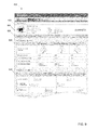
- an example interface 400 for displaying information about medical devices is shown.
- the service device 114 accesses information on the server device 112 using a browser to obtain the information.
- the example interface 400 includes authentication information 402 , such as a user name and password that are provided by the technician to access the information.
- a tab structure 404 allows the technician to access various pages associated with the interface 400 , including an overview page ( FIG. 4 ), a devices page ( FIGS. 5-11 ), and a reports page.
- the reports page provides access to various reporting features.
- reports such as a calibration due date report and a preventive maintenance schedule report that list devices that are due for calibration or preventive maintenance, respectively.
- Other reports include reports that list the devices by usage (e.g., the top “x” device usage report) to help the user manage device supplies and/or to manage device aging.
- Other example reports include: reports by transactions per device, which lists the number of transactions at each device; utility reports to identify different financial means to purchase equipment, such as illustrating pay per use versus up-front capital costs; location of device reports that list devices by location; top error reports, which list the most common errors by device; wireless drop-out rates reports, which list wireless-related data per device; trend reports on usage of certain parameters to determine appropriate workflows and consistency to process (e.g., identification of re-takes of vitals that may lean towards requiring better training for staff); and reports listing software/firmware versions, license activations, and applications loaded per device.
- the overview page provides a snapshot of an entire fleet of medical devices.
- this could include the medical devices of a particular location (e.g., hospital or clinic), or multiple locations (e.g., a group of hospitals maintained by an entity).
- a health module 406 provides a summary of the “health” of the medical devices.
- the health module 406 provides a graph showing the number of devices having no maintenance requirements, devices having upcoming maintenance requirements, and devices which currently require maintenance. In this example, the health information is shown in a graphical format.
- a location module 408 provides a summary of the location of the medical devices. This can include a particular location within a facility (e.g., which floor, wing, etc.) or the location among a plurality of facilities (e.g., which hospital each device is located). In this example, the floors upon which the devices are located are shown in a graphical format.
- a connection module 410 provides a summary of the connection state of the medical devices. This can include whether each medical devices is online (i.e., currently communicating with the server device 112 ) or offline (i.e., not currently communicating with the server device 112 ). This information is again provided in a graphical format.
- the interface 400 also provides an update module 412 that summarizes the current state of the firmware and software on the medical devices.
- the update module 412 summarizes the number of devices needing firmware upgrade, license upgrades, and application upgrades. Other examples are possible.
- the technician can use the information provided in the modules 406 , 408 , 410 , 412 to make basic decisions about maintenance of the medical devices. For example, if the summaries indicate that a large number of medical devices will soon need maintenance, the technician may use this information to schedule additional technicians to handle the demand.
- the interface 400 also includes a maintenance alert module 414 that provides more detail about the maintenance needs of each individual medical device.
- a maintenance alert module 414 that provides more detail about the maintenance needs of each individual medical device.
- each medical device needing maintenance is listed, and the particular maintenance needs are detailed.
- the first entry indicates the location of a medical device “CVSM 0001,” which is the first floor at Saint Mary's Hospital.
- the entry indicates the due date for the maintenance, which is “yesterday,” and the particular maintenance needed is CO2 sensor calibration.
- Other maintenance examples include temperature probe expiration (e.g., the probe expires after a given number of uses, such as 6000) and battery replacement.
- the “Order replacement” link can be selected by the technician to access information about ordering replacement parts and/or actually placing an order for the parts.
- the devices report back to the server device 112 with updated maintenance information.
- This updated maintenance information impacts the information that is displayed to the technician on the interface 400 .
- the CVSM 001 CO2 sensor is calibrated, the CVSM 001 will report that the maintenance has been performed the next time the CVSM 001 communicates with the server device 112 .
- the interface 400 can thereupon be updated by, for example, removing the entry for the CVSM 001 from the maintenance alert module 414 . Manual removal of entries is also possible.
- a search box 416 can be used.
- the technician can put a device's name (e.g., CVSM 001) or serial number (e.g., 1234567890) into the search box 416 to access information about the device, as described further below.
- a device's name e.g., CVSM 001
- serial number e.g., 1234567890
- a devices page 420 is shown on the interface 400 when selected on the tab structure 404 .
- the devices page 420 provides more detailed information about each of the medical devices.
- the devices page 420 provides each device's name, serial number, location, and connection state (e.g., online or offline, and duration for the current state).
- any maintenance requirements are listed for each medical device.
- a firmware upgrade is available, and for the CVSM 003, a battery is estimated to be needed to be replaced on Apr. 15, 2012.
- a link to order replacement parts is provided.
- the CVSM 005 requires a thermometer replacement.
- the devices page 420 also provides a filter pane 422 that allows the technician to filter the devices that are shown.
- the filter pane 422 allows for filtering by device type and/or location.
- a dropdown 430 is provided that allows the user to filter the devices that are shown on the devices page 420 by specific parameters, such as: maintenance required (e.g., maintenance, firmware upgrade, license update, or application update); or model type for the medical device.
- maintenance required e.g., maintenance, firmware upgrade, license update, or application update
- model type for the medical device.
- the devices page 420 is modified to list those devices needing firmware upgrades.
- details about the firmware upgrade are provided, along with a list of those devices that need the upgrade.
- a firmware upgrade module 434 is provided that allows the technician to select which devices to upgrade. For example, a checkbox is associated with each device listed, and the technician can select the checkboxes associated with the desired devices to upgrade. Upon selection, the “Approve Upgrade” button is selected to schedule the selected medical devices for firmware upgrades. As described further below, each of the selected devices will download the noted firmware and prompt the user for installation at the next reboot of the device.
- the filter pane 422 provides similar functionality if the location is selected, including a dropdown that allows the technician to filter the devices shown on the devices page 420 based on the location of the devices (e.g., at certain facilities and/or at certain locations within a facility).
- FIG. 8 another example of a devices page 520 is shown on the interface 400 .
- the devices page 520 is similar to that of the devices page 420 , except the data associated with each medical device is shown in a tabular, summary format. Icons are provided to indicate a type of maintenance required for certain devices, such as an icon 524 that indicates general maintenance is needed. This allows for device information to be shown in a more compact format.
- a modified filter pane 522 is provided that allows the user to filter the device shown based on location, model type, maintenance status, and/or connection state.
- a device details page 622 when a device is selected from the interface 400 , such as from the devices pages 420 , 520 .
- the device details page 622 includes a device summary module 624 providing the information about the device, such as device name, location, serial number, model number, IP address, Ethernet and Radio MAC addresses, and connection state.
- Log files associated with the medical device can be accessed, and information associated with the device (e.g., device name) can be edited.
- the device details page 622 provides a tab structure 626 that allows the technician to select between device information ( FIGS. 9-10 ), updates ( FIG. 11 ), or applications.
- a replacement schedule module 628 is provided.
- This module 628 provides information about the components that need to be replaced on the medical device.
- the components include an NIBP sensor, a thermometer, and a battery.
- the module 628 provides information about the cycle counts, expected life, average usage (e.g., per day), and estimated replacement date Links to access replacement parts are also provided.
- a calibration module 630 on the device details page 622 provides information about the calibration of the medical device. This includes the components needing calibration (e.g., host controller, thermometer, and NIBP sensor), as well as a schedule of when the last calibration was performed, and the next calibration is due. In this example, the schedule is displayed as a timeline that allows the technician to easily conceptualize maintenance needs over time.
- a device information module 632 provides detailed information about various aspects of the components of the device. This information can include firmware versions, hardware versions, manufacture dates, serial numbers, and warranty expirations. Other configurations are possible.
- an updates page 722 is provided that lists the new updates that are available for the medical device.
- the technician can review information about each update and access additional information about the updates (i.e., release notes). In addition, the technician can approve the updates separately or altogether.
- the device will download the selected update(s) and prompt the user for installation at the next reboot of the device.
- information about the deployed updates (both awaiting install and installed) is provided.
- FIG. 12 an example method 800 for providing maintenance information for medical devices is shown.
- information about the maintenance requirements of the medical devices is received.
- Such information can include maintenance needed for particular components associated with the medical devices and/or upgrades to firmware and/or software on the medical devices.
- the maintenance interface is updated based on the information received. This includes indicating that additional maintenance is needed and providing an indication that maintenance has been performed by, for example, removing the medical device from the entry indicating that maintenance is needed.
- FIG. 13 One example of such a method is provided in FIG. 13 .
- the firmware for a medical device is updated.
- the server device receives the current firmware information (e.g., version) for a medical device.
- the server device receives notification that a firmware update is available for the medical device.
- the medical device is listed as needing a firmware update.
- confirmation is provided to the server device to apply the firmware update.
- the server device notifies the medical device to update the firmware. This notification is typically provided the next time the medical device connects to the server device or an intermediate device communicating therewith.
- the medical device Upon notification, the medical device downloads the firmware. When the medical device next reboots, a prompt is provided to the user of the medical device requesting permission to apply the firmware update. Once applied, the medical device reports the update back to the server device.
- the server device receives notification that the firmware update was applied.
- the medical device is removed from the list of devices needing firmware updates.
- FIG. 14 illustrates example physical components of a computing device, such as the devices 102 , 104 , 112 , 114 .
- the device includes at least one central processing unit (“CPU”) 1708 , a system memory 1712 , and a system bus 1710 that couples the system memory 1712 to the CPU 1708 .
- the system memory 1712 includes a random access memory (“RAM”) 1718 and a read-only memory (“ROM”) 1720 .
- RAM random access memory
- ROM read-only memory
- the device further includes a mass storage device 1714 .
- the mass storage device 1714 is able to store software instructions and data.
- the mass storage device 1714 is connected to the CPU 1708 through a mass storage controller (not shown) connected to the bus 1710 .
- the mass storage device 1714 and its associated computer-readable data storage media provide non-volatile, non-transitory storage for the device.
- computer-readable data storage media can be any available non-transitory, physical device or article of manufacture from which the device can read data and/or instructions.
- Computer-readable data storage media include volatile and non-volatile, removable and non-removable media implemented in any method or technology for storage of information such as computer-readable software instructions, data structures, program modules or other data.
- Example types of computer-readable data storage media include, but are not limited to, RAM, ROM, EPROM, EEPROM, flash memory or other solid state memory technology, CD-ROMs, digital versatile discs (“DVDs”), other optical storage media, magnetic cassettes, magnetic tape, magnetic disk storage or other magnetic storage devices, or any other medium which can be used to store the desired information and which can be accessed by the device.
- the device may operate in a networked environment using logical connections to remote network devices through the network 108 , such as a local network, the Internet, or another type of network.
- the device connects to the network 108 through a network interface unit 1716 connected to the bus 1710 .
- the network interface unit 1716 may also be utilized to connect to other types of networks and remote computing systems.
- the device also includes an input/output controller 1722 for receiving and processing input from a number of other devices, including a keyboard, a mouse, a touch user interface display screen, or another type of input device. Similarly, the input/output controller 1722 may provide output to a touch user interface display screen, a printer, or other type of output device.
- the mass storage device 1714 and the RAM 1718 of the device can store software instructions and data.
- the software instructions include an operating system 1732 suitable for controlling the operation of the device.
- the mass storage device 1714 and/or the RAM 1718 also store software instructions, that when executed by the CPU 1708 , cause the device to provide the functionality of the device discussed in this document.
- the mass storage device 1714 and/or the RAM 1718 can store software instructions that, when executed by the CPU 1708 , cause the physiological monitor device to display the home screen 600 and other screens.
- the example medical devices described herein are devices used to monitor patients, other types of medical devices can also be used.
- the different components of the CONNEXTM system such as the intermediary servers that communication with the monitoring devices, can also require maintenance in the form of firmware and software updates.
- These intermediary servers can be managed by the systems and methods described herein to update the maintenance requirements of the servers.
Abstract
Description
Claims (8)
Priority Applications (3)
| Application Number | Priority Date | Filing Date | Title |
|---|---|---|---|
| US13/440,571 US9092762B2 (en) | 2012-04-05 | 2012-04-05 | Medical device maintenance system |
| PCT/US2013/031218 WO2013151713A1 (en) | 2012-04-05 | 2013-03-14 | Medical device maintenance system |
| US14/741,997 US10049346B2 (en) | 2012-04-05 | 2015-06-17 | Medical device maintenance system |
Applications Claiming Priority (1)
| Application Number | Priority Date | Filing Date | Title |
|---|---|---|---|
| US13/440,571 US9092762B2 (en) | 2012-04-05 | 2012-04-05 | Medical device maintenance system |
Related Child Applications (1)
| Application Number | Title | Priority Date | Filing Date |
|---|---|---|---|
| US14/741,997 Continuation US10049346B2 (en) | 2012-04-05 | 2015-06-17 | Medical device maintenance system |
Publications (2)
| Publication Number | Publication Date |
|---|---|
| US20130268890A1 US20130268890A1 (en) | 2013-10-10 |
| US9092762B2 true US9092762B2 (en) | 2015-07-28 |
Family
ID=49293323
Family Applications (2)
| Application Number | Title | Priority Date | Filing Date |
|---|---|---|---|
| US13/440,571 Active 2032-08-21 US9092762B2 (en) | 2012-04-05 | 2012-04-05 | Medical device maintenance system |
| US14/741,997 Active 2033-07-15 US10049346B2 (en) | 2012-04-05 | 2015-06-17 | Medical device maintenance system |
Family Applications After (1)
| Application Number | Title | Priority Date | Filing Date |
|---|---|---|---|
| US14/741,997 Active 2033-07-15 US10049346B2 (en) | 2012-04-05 | 2015-06-17 | Medical device maintenance system |
Country Status (2)
| Country | Link |
|---|---|
| US (2) | US9092762B2 (en) |
| WO (1) | WO2013151713A1 (en) |
Cited By (3)
| Publication number | Priority date | Publication date | Assignee | Title |
|---|---|---|---|---|
| US20170010874A1 (en) * | 2015-07-06 | 2017-01-12 | Cisco Technology, Inc. | Provisioning storage devices in a data center |
| US9729330B2 (en) * | 2015-08-21 | 2017-08-08 | Samsung Electronics Co., Ltd. | Secure pairing of eHealth devices and authentication of data using a gateway device having secured area |
| US11865352B2 (en) | 2020-09-30 | 2024-01-09 | Zoll Medical Corporation | Remote monitoring devices and related methods and systems with audible AED signal listening |
Families Citing this family (32)
| Publication number | Priority date | Publication date | Assignee | Title |
|---|---|---|---|---|
| US9737649B2 (en) | 2013-03-14 | 2017-08-22 | Smith & Nephew, Inc. | Systems and methods for applying reduced pressure therapy |
| US9558331B2 (en) | 2013-03-15 | 2017-01-31 | Carefusion 303, Inc. | Application licensing for a centralized system of medical devices |
| US9242043B2 (en) | 2013-03-15 | 2016-01-26 | Tandem Diabetes Care, Inc. | Field update of an ambulatory infusion pump system |
| JP2016062197A (en) * | 2014-09-16 | 2016-04-25 | 株式会社リコー | Information processing system and information processing device |
| CN104834537B (en) * | 2014-12-30 | 2018-04-27 | 沈阳东软医疗系统有限公司 | Data processing method, server and client |
| SG10202002519UA (en) * | 2015-09-21 | 2020-04-29 | Fisher & Paykel Healthcare Ltd | Maintenance systems and methods for medical devices |
| WO2017062042A1 (en) | 2015-10-07 | 2017-04-13 | Smith & Nephew, Inc. | Systems and methods for applying reduced pressure therapy |
| US10613524B2 (en) | 2016-01-15 | 2020-04-07 | Caterpillar Paving Products Inc. | Truck process management tool for transport operations |
| US10990245B2 (en) | 2016-01-15 | 2021-04-27 | Caterpillar Paving Products Inc. | Mobile process management tool for paving operations |
| US10474338B2 (en) | 2016-01-15 | 2019-11-12 | Caterpillar Paving Products Inc. | Control system for coordinating paving operations |
| US10541987B2 (en) | 2016-02-26 | 2020-01-21 | Tandem Diabetes Care, Inc. | Web browser-based device communication workflow |
| EP3454917B1 (en) | 2016-05-13 | 2022-04-06 | Smith & Nephew, Inc | Automatic wound coupling detection in negative pressure wound therapy systems |
| JP2017211839A (en) * | 2016-05-25 | 2017-11-30 | 横河電機株式会社 | Instrument maintenance device, instrument maintenance method, instrument maintenance program, and recording medium |
| EP3252635B1 (en) * | 2016-06-03 | 2019-12-04 | Fenwal, Inc. | Medical device connection status monitoring |
| JP7063887B2 (en) | 2016-09-29 | 2022-05-09 | スミス アンド ネフュー インコーポレイテッド | Construction and protection of components in negative pressure wound healing systems |
| JP6746232B2 (en) * | 2017-01-12 | 2020-08-26 | 九州旅客鉄道株式会社 | Radio station management system |
| JP6925893B2 (en) * | 2017-07-05 | 2021-08-25 | 日本光電工業株式会社 | Biometric information detection sensor wireless system, biometric information detection sensor wireless method, and biometric information detection sensor |
| US11712508B2 (en) | 2017-07-10 | 2023-08-01 | Smith & Nephew, Inc. | Systems and methods for directly interacting with communications module of wound therapy apparatus |
| GB2566295B (en) * | 2017-09-07 | 2022-06-22 | Spherica Systems Ltd | System and methods utilizing dataset management user interface |
| US20200365261A1 (en) * | 2017-10-25 | 2020-11-19 | Koninklijke Philips N.V. | Extracting sales and upgrade opportunities from utilization data |
| US10290371B1 (en) * | 2018-01-30 | 2019-05-14 | General Electric Company | System of medical devices and method of controlling the same |
| USD886860S1 (en) | 2018-05-21 | 2020-06-09 | Spherica Systems Limited | Display screen with computer graphical user interface |
| USD886859S1 (en) | 2018-05-21 | 2020-06-09 | Spherica Systems Limited | Display screen with computer graphical user interface |
| GB201820668D0 (en) | 2018-12-19 | 2019-01-30 | Smith & Nephew Inc | Systems and methods for delivering prescribed wound therapy |
| US10600512B1 (en) | 2019-08-18 | 2020-03-24 | Medigate tech Ltd. | Network-based calculation of prevalence of repeated medical imaging |
| US11056232B2 (en) | 2019-08-18 | 2021-07-06 | Medigate tech Ltd. | Medication usage auditing based on analysis of infusion pump network traffic |
| US10825566B1 (en) | 2019-08-18 | 2020-11-03 | Medigate tech Ltd. | Ensuring availability of medical devices to receive maintenance |
| US10658079B1 (en) | 2019-08-18 | 2020-05-19 | Medigate tech Ltd. | Crowd-based recommendations of a version of firmware for medical devices |
| US20230215555A1 (en) * | 2020-05-29 | 2023-07-06 | Carefusion 303, Inc. | Automated device maintenance support tool |
| WO2022118080A1 (en) * | 2020-12-01 | 2022-06-09 | Suresh A | System and method for service management and monitoring of instruments in healthcare organizations |
| US20240007294A1 (en) * | 2022-07-01 | 2024-01-04 | Welch Allyn, Inc. | Embedded servicing and authentication for medical device |
| CN116864096B (en) * | 2023-09-01 | 2023-11-21 | 齐齐哈尔市第一医院 | Medical equipment environment intelligent monitoring system based on internet |
Citations (15)
| Publication number | Priority date | Publication date | Assignee | Title |
|---|---|---|---|---|
| US20030182014A1 (en) * | 2002-03-22 | 2003-09-25 | Mcdonnell Ryan P. | Tool wear monitoring system |
| US20050137653A1 (en) | 2003-12-05 | 2005-06-23 | Friedman Gregory S. | System and method for network monitoring of multiple medical devices |
| JP2006149873A (en) | 2004-11-30 | 2006-06-15 | Toshiba Corp | Medical device control apparatus, method, and program |
| US20090005927A1 (en) * | 2002-11-18 | 2009-01-01 | Larry Schlatre | Integrated system for routine maintenance of mechanized equipment |
| US20090099867A1 (en) * | 2007-08-10 | 2009-04-16 | Smiths Medical Md, Inc. | Communicating preventative maintenance data to a medical device |
| US20090182594A1 (en) * | 2008-01-14 | 2009-07-16 | General Electric Company | System and method to manage assets of healthcare facility |
| US20100076809A1 (en) * | 2003-03-18 | 2010-03-25 | Fisher-Rosemount Systems, Inc. | Asset optimization reporting in a process plant |
| US20100131084A1 (en) * | 2008-11-25 | 2010-05-27 | Van Camp Kim O | Software deployment manager integration within a process control system |
| US20100287006A1 (en) * | 2009-05-07 | 2010-11-11 | Cerner Innovation, Inc. | Clinician to device association |
| US20110071420A1 (en) | 2009-09-18 | 2011-03-24 | St Pierre Shawn C | Physiological Parameter Measuring Platform Device Supporting Multiple Workflows |
| JP2011175575A (en) | 2010-02-25 | 2011-09-08 | Terumo Corp | Device and system for managing medical equipment |
| JP2011204205A (en) | 2010-03-26 | 2011-10-13 | Exscion:Kk | Medical equipment information management system |
| US20120095926A1 (en) * | 2010-09-30 | 2012-04-19 | International Business Machines Corporation | Method of Managing Asset Associated with Work Order or Element Associated with Asset, and System and Computer Program for the Same |
| US20120299727A1 (en) * | 2011-05-27 | 2012-11-29 | Illinois Tool Works Inc. | System and method for monitoring, controlling, and improving productivity and safety conditions of automated machinery |
| US8402161B2 (en) | 2005-03-30 | 2013-03-19 | Welch Allyn, Inc. | Communication of information between a plurality of network elements |
Family Cites Families (1)
| Publication number | Priority date | Publication date | Assignee | Title |
|---|---|---|---|---|
| US9298574B2 (en) * | 2011-04-14 | 2016-03-29 | Ricoh Company, Ltd. | Device management system including reporter server |
-
2012
- 2012-04-05 US US13/440,571 patent/US9092762B2/en active Active
-
2013
- 2013-03-14 WO PCT/US2013/031218 patent/WO2013151713A1/en active Application Filing
-
2015
- 2015-06-17 US US14/741,997 patent/US10049346B2/en active Active
Patent Citations (15)
| Publication number | Priority date | Publication date | Assignee | Title |
|---|---|---|---|---|
| US20030182014A1 (en) * | 2002-03-22 | 2003-09-25 | Mcdonnell Ryan P. | Tool wear monitoring system |
| US20090005927A1 (en) * | 2002-11-18 | 2009-01-01 | Larry Schlatre | Integrated system for routine maintenance of mechanized equipment |
| US20100076809A1 (en) * | 2003-03-18 | 2010-03-25 | Fisher-Rosemount Systems, Inc. | Asset optimization reporting in a process plant |
| US20050137653A1 (en) | 2003-12-05 | 2005-06-23 | Friedman Gregory S. | System and method for network monitoring of multiple medical devices |
| JP2006149873A (en) | 2004-11-30 | 2006-06-15 | Toshiba Corp | Medical device control apparatus, method, and program |
| US8402161B2 (en) | 2005-03-30 | 2013-03-19 | Welch Allyn, Inc. | Communication of information between a plurality of network elements |
| US20090099867A1 (en) * | 2007-08-10 | 2009-04-16 | Smiths Medical Md, Inc. | Communicating preventative maintenance data to a medical device |
| US20090182594A1 (en) * | 2008-01-14 | 2009-07-16 | General Electric Company | System and method to manage assets of healthcare facility |
| US20100131084A1 (en) * | 2008-11-25 | 2010-05-27 | Van Camp Kim O | Software deployment manager integration within a process control system |
| US20100287006A1 (en) * | 2009-05-07 | 2010-11-11 | Cerner Innovation, Inc. | Clinician to device association |
| US20110071420A1 (en) | 2009-09-18 | 2011-03-24 | St Pierre Shawn C | Physiological Parameter Measuring Platform Device Supporting Multiple Workflows |
| JP2011175575A (en) | 2010-02-25 | 2011-09-08 | Terumo Corp | Device and system for managing medical equipment |
| JP2011204205A (en) | 2010-03-26 | 2011-10-13 | Exscion:Kk | Medical equipment information management system |
| US20120095926A1 (en) * | 2010-09-30 | 2012-04-19 | International Business Machines Corporation | Method of Managing Asset Associated with Work Order or Element Associated with Asset, and System and Computer Program for the Same |
| US20120299727A1 (en) * | 2011-05-27 | 2012-11-29 | Illinois Tool Works Inc. | System and method for monitoring, controlling, and improving productivity and safety conditions of automated machinery |
Non-Patent Citations (2)
| Title |
|---|
| International Search Report & Written Opinion in PCT/US2013/031218 mailed Jun. 20, 2013, 11 pages. |
| Rahul Nair et al., Fleet Management for Vehicle Sharing Operations, Nov. 2011, Journal Transportation Science, vol. 45 Issue 4, pp. 524-540. * |
Cited By (3)
| Publication number | Priority date | Publication date | Assignee | Title |
|---|---|---|---|---|
| US20170010874A1 (en) * | 2015-07-06 | 2017-01-12 | Cisco Technology, Inc. | Provisioning storage devices in a data center |
| US9729330B2 (en) * | 2015-08-21 | 2017-08-08 | Samsung Electronics Co., Ltd. | Secure pairing of eHealth devices and authentication of data using a gateway device having secured area |
| US11865352B2 (en) | 2020-09-30 | 2024-01-09 | Zoll Medical Corporation | Remote monitoring devices and related methods and systems with audible AED signal listening |
Also Published As
| Publication number | Publication date |
|---|---|
| US10049346B2 (en) | 2018-08-14 |
| WO2013151713A1 (en) | 2013-10-10 |
| US20130268890A1 (en) | 2013-10-10 |
| US20150371198A1 (en) | 2015-12-24 |
Similar Documents
| Publication | Publication Date | Title |
|---|---|---|
| US10049346B2 (en) | Medical device maintenance system | |
| US10404776B2 (en) | Extensibility for manipulation of medical data | |
| US10226200B2 (en) | User interface enhancements for physiological parameter monitoring platform devices | |
| US8510126B2 (en) | Patient monitoring | |
| US7996074B2 (en) | System and method for providing closely-followed cardiac therapy management through automated patient care | |
| US20150342538A1 (en) | Custom early warning scoring for medical device | |
| US10679739B2 (en) | Management of implantable cardiac device interrogation data and reports | |
| US20120130197A1 (en) | Quality measurements reporting for patient care | |
| US20170262605A1 (en) | Remote monitoring of medical devices | |
| EP2852906A1 (en) | Medical device information portal | |
| JP2019517380A (en) | User interface for configurable display of real-time data for multiple patients | |
| JP2012139492A (en) | Patient enabled method, apparatus, and system for early health and preventive care using wearable sensor | |
| US20110246234A1 (en) | Patient matching | |
| WO2014144846A1 (en) | Automated alerts for medical indicators | |
| US10915315B2 (en) | Medical device, system, and software architecture for monitoring low acuity vitals | |
| US9804836B2 (en) | Medical device nucleus architecture | |
| Janckulık et al. | Personal Telemetric System–Guardian | |
| US20170270266A1 (en) | Tool for allowing clinicians to define alert/trigger rules for testing devices | |
| US11699528B2 (en) | Falls risk management | |
| US20110246222A1 (en) | Reviewing tests on client devices | |
| US11298087B2 (en) | Method and system for predicting physiological alarm frequency by patient monitors | |
| JP2021506039A (en) | Systems and methods for managing patient medical devices |
Legal Events
| Date | Code | Title | Description |
|---|---|---|---|
| AS | Assignment |
Owner name: WELCH ALLYN, INC., NEW YORK Free format text: ASSIGNMENT OF ASSIGNORS INTEREST;ASSIGNORS:JENSEN, ERIC P.;DIFRAIA, JASON PAUL;EHRHART, MICHAEL ALLAN;SIGNING DATES FROM 20120404 TO 20120405;REEL/FRAME:028014/0121 |
|
| STCF | Information on status: patent grant |
Free format text: PATENTED CASE |
|
| AS | Assignment |
Owner name: JPMORGAN CHASE BANK, N.A., AS COLLATERAL AGENT, ILLINOIS Free format text: SECURITY INTEREST;ASSIGNORS:ALLEN MEDICAL SYSTEMS, INC.;HILL-ROM SERVICES, INC.;ASPEN SURGICAL PRODUCTS, INC.;AND OTHERS;REEL/FRAME:036582/0123 Effective date: 20150908 Owner name: JPMORGAN CHASE BANK, N.A., AS COLLATERAL AGENT, IL Free format text: SECURITY INTEREST;ASSIGNORS:ALLEN MEDICAL SYSTEMS, INC.;HILL-ROM SERVICES, INC.;ASPEN SURGICAL PRODUCTS, INC.;AND OTHERS;REEL/FRAME:036582/0123 Effective date: 20150908 |
|
| AS | Assignment |
Owner name: JPMORGAN CHASE BANK, N.A., AS COLLATERAL AGENT, ILLINOIS Free format text: SECURITY AGREEMENT;ASSIGNORS:HILL-ROM SERVICES, INC.;ASPEN SURGICAL PRODUCTS, INC.;ALLEN MEDICAL SYSTEMS, INC.;AND OTHERS;REEL/FRAME:040145/0445 Effective date: 20160921 Owner name: JPMORGAN CHASE BANK, N.A., AS COLLATERAL AGENT, IL Free format text: SECURITY AGREEMENT;ASSIGNORS:HILL-ROM SERVICES, INC.;ASPEN SURGICAL PRODUCTS, INC.;ALLEN MEDICAL SYSTEMS, INC.;AND OTHERS;REEL/FRAME:040145/0445 Effective date: 20160921 |
|
| MAFP | Maintenance fee payment |
Free format text: PAYMENT OF MAINTENANCE FEE, 4TH YEAR, LARGE ENTITY (ORIGINAL EVENT CODE: M1551); ENTITY STATUS OF PATENT OWNER: LARGE ENTITY Year of fee payment: 4 |
|
| AS | Assignment |
Owner name: HILL-ROM COMPANY, INC., ILLINOIS Free format text: RELEASE BY SECURED PARTY;ASSIGNOR:JPMORGAN CHASE BANK, N.A.;REEL/FRAME:050254/0513 Effective date: 20190830 Owner name: WELCH ALLYN, INC., NEW YORK Free format text: RELEASE BY SECURED PARTY;ASSIGNOR:JPMORGAN CHASE BANK, N.A.;REEL/FRAME:050254/0513 Effective date: 20190830 Owner name: HILL-ROM SERVICES, INC., ILLINOIS Free format text: RELEASE BY SECURED PARTY;ASSIGNOR:JPMORGAN CHASE BANK, N.A.;REEL/FRAME:050254/0513 Effective date: 20190830 Owner name: MORTARA INSTRUMENT, INC., WISCONSIN Free format text: RELEASE BY SECURED PARTY;ASSIGNOR:JPMORGAN CHASE BANK, N.A.;REEL/FRAME:050254/0513 Effective date: 20190830 Owner name: HILL-ROM, INC., ILLINOIS Free format text: RELEASE BY SECURED PARTY;ASSIGNOR:JPMORGAN CHASE BANK, N.A.;REEL/FRAME:050254/0513 Effective date: 20190830 Owner name: MORTARA INSTRUMENT SERVICES, INC., WISCONSIN Free format text: RELEASE BY SECURED PARTY;ASSIGNOR:JPMORGAN CHASE BANK, N.A.;REEL/FRAME:050254/0513 Effective date: 20190830 Owner name: ANODYNE MEDICAL DEVICE, INC., FLORIDA Free format text: RELEASE BY SECURED PARTY;ASSIGNOR:JPMORGAN CHASE BANK, N.A.;REEL/FRAME:050254/0513 Effective date: 20190830 Owner name: VOALTE, INC., FLORIDA Free format text: RELEASE BY SECURED PARTY;ASSIGNOR:JPMORGAN CHASE BANK, N.A.;REEL/FRAME:050254/0513 Effective date: 20190830 Owner name: ALLEN MEDICAL SYSTEMS, INC., ILLINOIS Free format text: RELEASE BY SECURED PARTY;ASSIGNOR:JPMORGAN CHASE BANK, N.A.;REEL/FRAME:050254/0513 Effective date: 20190830 |
|
| AS | Assignment |
Owner name: JPMORGAN CHASE BANK, N.A., ILLINOIS Free format text: SECURITY AGREEMENT;ASSIGNORS:HILL-ROM HOLDINGS, INC.;HILL-ROM, INC.;HILL-ROM SERVICES, INC.;AND OTHERS;REEL/FRAME:050260/0644 Effective date: 20190830 |
|
| AS | Assignment |
Owner name: HILL-ROM HOLDINGS, INC., ILLINOIS Free format text: RELEASE OF SECURITY INTEREST AT REEL/FRAME 050260/0644;ASSIGNOR:JPMORGAN CHASE BANK, N.A.;REEL/FRAME:058517/0001 Effective date: 20211213 Owner name: BARDY DIAGNOSTICS, INC., ILLINOIS Free format text: RELEASE OF SECURITY INTEREST AT REEL/FRAME 050260/0644;ASSIGNOR:JPMORGAN CHASE BANK, N.A.;REEL/FRAME:058517/0001 Effective date: 20211213 Owner name: VOALTE, INC., FLORIDA Free format text: RELEASE OF SECURITY INTEREST AT REEL/FRAME 050260/0644;ASSIGNOR:JPMORGAN CHASE BANK, N.A.;REEL/FRAME:058517/0001 Effective date: 20211213 Owner name: HILL-ROM, INC., ILLINOIS Free format text: RELEASE OF SECURITY INTEREST AT REEL/FRAME 050260/0644;ASSIGNOR:JPMORGAN CHASE BANK, N.A.;REEL/FRAME:058517/0001 Effective date: 20211213 Owner name: WELCH ALLYN, INC., NEW YORK Free format text: RELEASE OF SECURITY INTEREST AT REEL/FRAME 050260/0644;ASSIGNOR:JPMORGAN CHASE BANK, N.A.;REEL/FRAME:058517/0001 Effective date: 20211213 Owner name: ALLEN MEDICAL SYSTEMS, INC., ILLINOIS Free format text: RELEASE OF SECURITY INTEREST AT REEL/FRAME 050260/0644;ASSIGNOR:JPMORGAN CHASE BANK, N.A.;REEL/FRAME:058517/0001 Effective date: 20211213 Owner name: HILL-ROM SERVICES, INC., ILLINOIS Free format text: RELEASE OF SECURITY INTEREST AT REEL/FRAME 050260/0644;ASSIGNOR:JPMORGAN CHASE BANK, N.A.;REEL/FRAME:058517/0001 Effective date: 20211213 Owner name: BREATHE TECHNOLOGIES, INC., CALIFORNIA Free format text: RELEASE OF SECURITY INTEREST AT REEL/FRAME 050260/0644;ASSIGNOR:JPMORGAN CHASE BANK, N.A.;REEL/FRAME:058517/0001 Effective date: 20211213 |
|
| MAFP | Maintenance fee payment |
Free format text: PAYMENT OF MAINTENANCE FEE, 8TH YEAR, LARGE ENTITY (ORIGINAL EVENT CODE: M1552); ENTITY STATUS OF PATENT OWNER: LARGE ENTITY Year of fee payment: 8 |