US9112620B2 - Method of enabling power savings when no data is being transmitted on a media logical channel - Google Patents
Method of enabling power savings when no data is being transmitted on a media logical channel Download PDFInfo
- Publication number
- US9112620B2 US9112620B2 US11/369,376 US36937606A US9112620B2 US 9112620 B2 US9112620 B2 US 9112620B2 US 36937606 A US36937606 A US 36937606A US 9112620 B2 US9112620 B2 US 9112620B2
- Authority
- US
- United States
- Prior art keywords
- frame
- data
- communications device
- sleep periods
- overhead portion
- Prior art date
- Legal status (The legal status is an assumption and is not a legal conclusion. Google has not performed a legal analysis and makes no representation as to the accuracy of the status listed.)
- Expired - Fee Related, expires
Links
Images


Classifications
-
- H—ELECTRICITY
- H04—ELECTRIC COMMUNICATION TECHNIQUE
- H04H—BROADCAST COMMUNICATION
- H04H40/00—Arrangements specially adapted for receiving broadcast information
- H04H40/18—Arrangements characterised by circuits or components specially adapted for receiving
-
- H—ELECTRICITY
- H04—ELECTRIC COMMUNICATION TECHNIQUE
- H04B—TRANSMISSION
- H04B1/00—Details of transmission systems, not covered by a single one of groups H04B3/00 - H04B13/00; Details of transmission systems not characterised by the medium used for transmission
- H04B1/06—Receivers
- H04B1/16—Circuits
- H04B1/1607—Supply circuits
- H04B1/1615—Switching on; Switching off, e.g. remotely
-
- H—ELECTRICITY
- H04—ELECTRIC COMMUNICATION TECHNIQUE
- H04W—WIRELESS COMMUNICATION NETWORKS
- H04W52/00—Power management, e.g. TPC [Transmission Power Control], power saving or power classes
- H04W52/02—Power saving arrangements
- H04W52/0209—Power saving arrangements in terminal devices
- H04W52/0225—Power saving arrangements in terminal devices using monitoring of external events, e.g. the presence of a signal
- H04W52/0229—Power saving arrangements in terminal devices using monitoring of external events, e.g. the presence of a signal where the received signal is a wanted signal
-
- Y02B60/50—
-
- Y—GENERAL TAGGING OF NEW TECHNOLOGICAL DEVELOPMENTS; GENERAL TAGGING OF CROSS-SECTIONAL TECHNOLOGIES SPANNING OVER SEVERAL SECTIONS OF THE IPC; TECHNICAL SUBJECTS COVERED BY FORMER USPC CROSS-REFERENCE ART COLLECTIONS [XRACs] AND DIGESTS
- Y02—TECHNOLOGIES OR APPLICATIONS FOR MITIGATION OR ADAPTATION AGAINST CLIMATE CHANGE
- Y02D—CLIMATE CHANGE MITIGATION TECHNOLOGIES IN INFORMATION AND COMMUNICATION TECHNOLOGIES [ICT], I.E. INFORMATION AND COMMUNICATION TECHNOLOGIES AIMING AT THE REDUCTION OF THEIR OWN ENERGY USE
- Y02D30/00—Reducing energy consumption in communication networks
- Y02D30/70—Reducing energy consumption in communication networks in wireless communication networks
Definitions
- the present invention relates generally to power savings in a communications network. More specifically, the present invention relates to determining periods of interrupted data transmission to facilitate power savings in a wireless communications network.
- FLO is a technology designed primarily for the efficient and economical distribution of the same multimedia content to millions of wireless subscribers simultaneously.
- the goal of FLO technology is to reduce costs associated with delivering such content and allow users to surf channels of content on the mobile handsets typically used for traditional cellular voice and data services.
- This multimedia content is also known as services.
- a service is an aggregation of one or more independent data components. Each independent data component of a service is called a flow.
- Wide-area services are classified into two types based on their coverage: Wide-area services and Local-area services.
- a Local-area service is multicast for reception within a metropolitan area.
- Wide-area services are multicast in one or more metropolitan areas.
- FLO services are carried over one or more logical channels, known as MediaFLOTM Logical Channels or MLCs.
- An MLC may be divided into a maximum of three logical sub-channels. These logical sub-channels are called streams. Each flow is carried in a single stream.
- FLO networks transmit the content for a service or MLC, every super-frame. There can be intermittent periods when there is no data being transmitted by the network for a certain duration on the MLC. If the device is forced to search for the MLC during these intermittent time periods, the device will be forced to consume power by performing this unnecessary search. This unnecessary power consumption will ultimately reduce battery life.
- the present invention includes a method for determining sleep periods within a communications device configured to communicate via a network.
- the method includes analyzing at least one of two or more data fields related to a data unit and determining device sleep periods based upon said analysis.
- an apparatus determines sleep periods within a communications device.
- the apparatus includes means for analyzing at least one of two or more data fields related to a data unit and means for determining device sleep periods based upon the analysis.
- a transceiver determines sleep periods associated with communicating via a network.
- the transceiver includes a processor configured to analyze at least one of two or more data fields related to a data unit and a timer for determining device sleep periods based upon the analysis.
- a computer readable medium carrying one or more sequences of one or more instructions for execution by one or more processors to perform a method of determining sleep periods within a communications device.
- the instructions when executed by the one or more processors, cause the one or more processors to perform the steps of analyzing at least one of two or more data fields related to a data unit and determining device sleep periods based upon the analysis.
- the network may transmit data every super-frame. However, the network is not prohibited from temporarily halting transmission on that MLC for a certain time period.
- a device that is monitoring this particular MLC may implement power saving functions, such as receiver sleep mode, during the time period for which there is no MLC data available.
- An overhead information symbols (OIS) system parameters message as well as an OIS capsule header carried as a part of the MLC data, carries information on when the network is expected to resume transmitting data on a particular MLC. This information is specified in terms of an offset in the number of super-frames. This offset ensures that the network will not transmit the data on the particular MLC before the specified offset. The device may use the time period indicated by this offset to perform any power saving functions.
- OIS overhead information symbols
- the OIS and an embedded OIS carry information regarding the time interval (offset in super-frames) for which no data will be available associated with a particular MLC.
- this field guarantees that no data will be transmitted by the network for that MLC, for at least the specified time interval. This enables the device to sleep for that duration resulting in decreased power consumption and consequently increased battery life.
- FIG. 1 is an illustration of a network including one embodiment of a content delivery system
- FIG. 2 is an illustration of one embodiment of a content provider suitable for use in the content delivery system of FIG. 1 ;
- FIG. 3 is an illustration of one embodiment of a content server suitable for use in the content delivery system
- FIG. 4 is an illustration of an exemplary super-frame in accordance with the embodiment
- FIG. 5 is a block diagram illustration of an exemplary services flow in accordance with the embodiment.
- FIG. 6 is an illustration of the absence and presence of MLCs in associated contiguous super-frames
- FIG. 7 is an illustration of an exemplary MLC record constructed in accordance with the embodiment.
- FIG. 8 is a flow diagram of an exemplary method of practicing the embodiment.
- FIG. 9 is a block diagram of an exemplary apparatus constructed in accordance with the embodiment.
- FIG. 1 shows a communication network 100 that comprises a transport system 136 that operates to create and transport multimedia content flows across data networks.
- the transport system 136 is consistent with the principles of the FLO system, noted above, and is suitable for use in transporting content clips from a content provider network to a wireless access network for broadcast distribution.
- the network 100 comprises a content provider (CP) 102 , a content provider network 104 , an optimized broadcast network 106 , and a wireless access network 108 .
- the network 100 also includes devices 110 that comprise a mobile telephone 112 , a personal digital assistance (PDA) 114 , and a notebook computer 116 .
- the devices 110 illustrate just some of the devices that are suitable for use with the transport system 136 . It should be noted that although three devices are shown in FIG. 1 , virtually any number of analogous devices, or types of devices are suitable for use in the transport system 136 , as would be apparent to those skilled in the relevant art.
- the content provider 102 operates to provide content for distribution to users in the network 100 .
- the content comprises video, audio, multimedia content, clips, real-time and non real-time content, scripts, programs, data or any other type of suitable content.
- the content provider 102 provides the content to the content provider network 104 for distribution.
- the content provider 102 communicates with the content provider network 104 via the communication link 118 , which comprises any suitable type of wired and/or wireless communication link.
- the content provider network 104 comprises any combination of wired and wireless networks that operate to distribute content for delivery to users.
- the content provider network 104 communicates with the optimized broadcast network 106 via the link 120 .
- the link 120 comprises any suitable type of wired and/or wireless communication link.
- the optimized broadcast network 106 comprises any combination of wired and wireless networks that are designed to broadcast high quality content.
- the optimized broadcast network 106 may be a specialized proprietary network that has been optimized to deliver high quality content to selected devices over a plurality of optimized communication channels.
- the transport system 136 operates to deliver content from the content provider 102 for distribution to a content server (CS) 122 at the content provider network 104 that operates to communicate with a broadcast base station (BBS) 124 at the wireless access network.
- the CS 122 and the BBS 124 communicate using one or more embodiments of a transport interface 126 that allows the content provider network 104 to deliver content in the form of content flows to the wireless access network 108 for broadcast/multicast to the devices 110 .
- the transport interface 126 comprises a control interface 128 and a bearer channel 130 .
- the control interface 128 operates to allow the CS 122 to add, change, cancel, or otherwise modify contents flows that flow from the content provider network 104 to the wireless access network 108 .
- the bearer channel 130 operates to transport the content flows from the content provider network 104 to the wireless access network 108 .
- the CS 122 uses the transport interface 126 to schedule a content flow to be transmitted to the BBS 124 for broadcast/multicast over the wireless access network 108 .
- the content flow may comprise a non real-time content clip that was provided by the content provider 102 for distribution using the content provider network 104 .
- the CS 122 operates to negotiate with the BBS 124 to determine one or more parameters associated with the content clip. Once the BBS 124 receives the content clip, it broadcasts/multicasts the content clip over the wireless access network 108 for reception by one or more of the devices 110 . Any of the devices 110 may be authorized to receive the content clip and cache it for later viewing by the device user.
- the device 110 comprises a client program 132 that operates to provide a program guide that displays a listing of content that is scheduled for broadcast over the wireless access network 108 .
- the device user may then select to receive any particular content for rendering in real-time or to be stored in a cache 134 for later viewing.
- the content clip may be scheduled for broadcast during the evening hours, and the device 112 operates to receive the broadcast and cache the content clip in the cache 134 so that the device user may view the clip the next day.
- the content is broadcast as part of a subscription service and the receiving device may need to provide a key or otherwise authenticate itself to receive the broadcast.
- the transport system 136 allows the CS 122 to receive program-guide records, Program contents, and other related information from content provider 102 .
- the CS 122 updates and/or creates content for delivery to devices 110 .
- FIG. 2 shows a content provider server 200 suitable for use in the content delivery system.
- the server 200 may be used as the server 102 in FIG. 1 .
- the server 200 comprises processing logic 202 , resources and interfaces 204 , and transceiver logic 210 , all coupled to an internal data bus 212 .
- the server 200 also comprises activation logic 214 , PG 206 , and Guide State logic 208 , which are also coupled to the data bus 212 .
- the processing logic 202 comprises a central processing unit (CPU), processor, gate array, hardware logic, memory elements, virtual machine, software, and/or any combination of hardware and software.
- the processing logic 202 generally comprises logic to execute machine-readable instructions and to control one or more other functional elements of the server 200 via the internal data bus 212 .
- the resources and interfaces 204 comprise hardware and/or software that allow the server 200 to communicate with internal and external systems.
- the internal systems may include mass storage systems, memory, display driver, modem, or other internal device resources.
- the external systems may include user interface devices, printers, disk drives, or other local devices or systems.
- the transceiver logic 210 comprises hardware logic and/or software that operates to allow the server 200 to transmit and receive data and/or other information with remote devices or systems using communication channel 216 .
- the communication channel 216 comprises any suitable type of communication link to allow the server 200 to communicate with a data network.
- the activation logic 214 comprises a CPU, processor, gate array, hardware logic, memory elements, virtual machine, software, and/or any combination of hardware and software.
- the activation logic 214 operates to activate a CS and/or a device to allow the CS and/or the device to select and receive content and/or services described in the PG 206 .
- the activation logic 214 transmits a client program 220 to the CS and/or the device during the activation process.
- the client program 220 runs on the CS and/or the device to receive the PG 206 and display information about available content or services to the device user.
- the activation logic 214 operates to authenticate a CS and/or a device, download the client 220 , and download the PG 206 for rendering on the device by the client 220 .
- the PG 206 comprises information in any suitable format that describes content and/or services that are available for devices to receive.
- the PG 206 may be stored in a local memory of the server 200 and may comprise information such as content or service identifiers, scheduling information, pricing, and/or any other type of relevant information.
- the PG 206 comprises one or more identifiable sections that are updated by the processing logic 202 as changes are made to the available content or services.
- the Guide State logic 208 comprises hardware and/or software that operates to generate notification messages that identify and/or describe changes to the PG 206 . For example, when the processing logic 202 updates the PG 206 , the PG records logic 208 is notified about the changes. The Guide State logic 208 then generates one or more notification messages that are transmitted to CSs, which may have been activated with the server 200 , so that these CSs are promptly notified about the changes to the PG 206 .
- a broadcast indicator is provided that indicates when a section of the PG identified in the message will be broadcast.
- the broadcast indicator may comprise one bit to indicate that the section will be broadcast and a time indicator that indicates when the broadcast will occur.
- the CSs and/or the devices wishing to update their local copy of the PG records can listen for the broadcast at the designated time to receive the updated section of the PG records.
- the content delivery notification system comprises program instructions stored on a computer-readable media, which when executed by a processor, for instance, the processing logic 202 , provides the functions of the server 200 described herein.
- the program instructions may be loaded into the server 200 from a computer-readable media, such as a floppy disk, CDROM, memory card, FLASH memory device, RAM, ROM, or any other type of memory device or computer-readable media that interfaces to the server 200 through the resources 204 .
- the instructions may be downloaded into the server 200 from an external device or network resource that interfaces to the server 200 through the transceiver logic 210 .
- the program instructions when executed by the processing logic 202 , provide a guide state notification system as described herein.
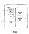
- FIG. 3 shows a content server (CS) or device 300 suitable for use in a content delivery system.
- CS 300 may be the CS 122 shown in FIG. 1 .
- the CS 300 comprises processing logic 302 , resources and interfaces 304 , and transceiver logic 306 , all coupled to a data bus 308 .
- the CS 300 also comprises a client 310 , and a Program Guide PG logic 312 , which are also coupled to the data bus 308 .
- the processing logic 302 comprises a CPU, processor, gate array, hardware logic, memory elements, virtual machine, software, and/or any combination of hardware and software.
- the processing logic 302 generally comprises logic configured to execute machine-readable instructions and to control one or more other functional elements of the CS 300 via the internal data bus 308 .
- the resources and interfaces 304 comprise hardware and/or software that allow the CS 300 to communicate with internal and external systems.
- internal systems may include mass storage systems, memory, display driver, modem, or other internal device resources.
- the external systems may include user interface devices, printers, disk drives, or other local devices or systems.
- the transceiver logic 306 comprises hardware and/or software that operate to allow the CS 300 to transmit and receive data and/or other information with external devices or systems through communication channel 314 .
- the communication channel 314 may comprise a network communication link, a wireless communication link, or any other type of communication link.
- the CS 300 is activated so that it may receive available content Or services over a data network.
- the CS 300 identifies itself to a content provider server during an activation process.
- the CS 300 receives and stores PG records by PG logic 312 .
- the PG 312 contains information that identifies content or services available for the CS 300 to receive.
- the client 310 operates to render information in the PG logic 312 on the CS and/or the device 300 using the resources and interfaces 304 .
- the client 310 renders information in the PG logic 312 on a display screen that is part of the device.
- the client 310 also receives user input through the resources and interfaces so that a device user may select content or services.
- the CS 300 receives notification messages through the transceiver logic 306 .
- the messages may be broadcast or unicast to the CS 300 and received by the transceiver logic 306 .
- the PG notification messages identify updates to the PG records at the PG logic 312 .
- the client 310 processes the PG notification messages to determine whether the local copy at the PG logic 312 needs to be updated.
- the notification messages include a section identifier, start time, end time, and version number.
- the CS 300 operates to compare the information in the PG notification messages to locally stored information at the existing PG logic 312 . If the CS 300 determines from the PG notification messages that one or more sections of the local copy at the PG logic 312 needs to be updated, the CS 300 operates to receive the updated sections of the PG in one of several ways. For example, the updated sections of the PG may be broadcast at a time indicated in the PG notification messages, so that the transceiver logic 306 may receive the broadcasts and pass the updated sections to the CS 300 , which in turn updates the local copy at the PG logic 312 .
- the CS 300 determines which sections of the PG need to be updated based on the received PG update notification messages, and transmits a request to a CP server to obtain the desired updated sections of the PG.
- the request may be formatted using any suitable format and comprise information such as a requesting CS identifier, section identifier, version number, and/or any other suitable information.
- the CS 300 performs one or more of the following functions in one or more embodiments of a PG notification system. It should be noted that the following functions might be changed, rearranged, modified, added to, deleted, or otherwise adjusted within the scope of the invention.
- the CS is activated for operation with a content provider system to receive content or services. As part of the activation process, a client and PG are transmitted to the CS.
- One or more PG notification messages are received by the CS and used to determine if one or more sections of the locally stored PG need to be updated.
- the CS listens to a broadcast from the distribution system to obtain the updated sections of the PG that it needs to update its local copy.
- the CS transmits one or more request messages to the CP to obtain the updated sections of the PG it needs.
- the CP transmits the updated sections of the PG to the CS.
- the CS uses the received updated sections of the PG to update its local copy of the PG.
- the content delivery system comprises program instructions which may be stored on a computer-readable media, which when executed by a processor, such as the processing logic 302 , provides the functions of the content delivery notification system as described herein.
- a processor such as the processing logic 302
- instructions may be loaded into the CS 300 from a computer-readable media, such as a floppy disk, CDROM, memory card, FLASH memory device, RAM, ROM, or any other type of memory device or computer-readable media that interfaces to the CS 300 through the resources and interfaces 304 .
- the instructions may be downloaded into the CS 300 from a network resource that interfaces to the CS 300 through the transceiver logic 306 .
- the instructions when executed by the processing logic 302 , provide a content delivery system as described herein.
- CS 300 represents just one implementation and that other implementations are possible within the scope of the invention.
- FIG. 4 is an illustration of a segment 400 of a transmitted signal within network 100 .
- signal transmission throughout the network 100 can include orthogonal frequency division multiplexed (OFDM) principles.
- Transmitted signals in the network 100 are organized into super-frames, which are units of data transmission in a physical layer of the network 100 .
- the network physical layer provides the channel structure, frequency, power output, modulation and encoding specification for the network's Forward Link.
- the segment 400 includes representative super-frames 402 and 404 .
- Each of the super-frames 402 and 404 has a duration of about one second and includes content related to OFDM symbols.
- each of the super-frames 402 and 404 includes about 1200 OFDM symbols, although this particular number (1200) is transparent to implementation of embodiments of the instant invention.
- certain of the 1200 symbols are representative of overhead information and certain of the symbols are representative of actual data.
- data can include, for example, video data and audio data related to a flow multicast.
- the FLO based network 100 multicasts several services as an aggregation of one or more independent data components.
- Each independent data component is called a flow and can include a video component, audio component, text or signaling component of a service.
- FLO services are carried over one or more logical channels MLCs.
- the representative super-frame 402 includes an overhead portion 406 and a data portion 407 .
- the data portion 407 is further subdivided to include data frames F 1 -F 4 .
- MLCs are transported within the data portion 407 .
- a transported MLC will be divided across the data frames F 1 -F 4 .
- three MLCs ( 10 , 20 , and 30 ) are divided across the data frames F 1 -F 4 . That is, one fourth of the content of each of the MLCs 10 , 20 , and 30 is carried in each of the frame F 1 -F 4 , respectively.
- the MLC having identification (ID) 10 is divided into portions 408 a - 408 d , each corresponding to one of the frames F 1 -F 4 .
- the frame F 1 also includes MLC portions 410 and 412 , corresponding to the MLCs 20 and 30 , respectively, as well as the portion 408 a , which corresponds to the MLC 10 .
- an MLC is a logical grouping at the physical layer that is configured to carry unique data.
- data also known as flows, are carried in entities known as streams.
- the Application layer provides services for an application to ensure that effective communication with another application program in a network is possible.
- the streams are in turn, carried in MLCs.
- a single MLC can carry up to three streams (i.e., up to three different flows of different application level data).
- FIG. 5 is an illustration of the relationship between a flow, a stream, and an MLC in accordance with principles of the present embodiment.
- an exemplary flow 500 might include information downloaded to the device 112 from a video mobile service provided, for example, by the cable news network (CNN).
- This broadcast from CNN can include application level data in the form of a video stream 502 , an audio stream 504 , and a text stream 506 .
- Each of the streams 502 , 504 , and 506 , carrying unique data, will be transmitted in the physical layer of the network 100 within the uniquely identifiable MLC 10 .
- one fourth of the MLC 10 which carries the streams 502 , 504 , and 506 , is carried in each of the frames F 1 -F 4 of the super-frame 402 in the form of the portions 408 a - 408 d , respectively.
- a super-frame can also be viewed as a network pipe. Different MLCs corresponding to different flows are carried within this network pipe, such as the super-frame 402 .
- an ESPN flow and a MSNBC flow might also be carried with the super-frame 402 , in addition to the CNN flow 500 .
- the ESPN flow might be carried within the MLC 20 and the MSNBC flow might be carried within the MLC 30 , shown in FIG. 4 .
- a single super-frame can carry many different flows, each representing different data types.
- the super-frames within the network 100 such as the super-frame 402 , will be transmitted to one or more of the devices 110 at a rate of about one per second.
- a service such as CNN
- that service will be mapped onto individual flows. Once the service has been mapped onto individual flows, each flow will be mapped to a specific MLC for physical transmission throughout the network 100 . At this point, the device 112 will pick up the associated MLC ID that is actually being transmitted by the network 100 .
- the device 112 will seek to determine the MLC ID structure within the super-frame 402 , and at least one subsequent super-frame, to determine the shape and location of the MLC 10 . Thus, every second, the device is looking in a super-frame for the MLC 10 .
- the MLC 10 may contain actual data in some super-frames, but in other super-frames, the MLC 10 may have no data at all. This intermittent presence of data in some MLCs and absence in others unnecessarily consumes valuable network power. This network power is unnecessarily consumed because the device 112 dissipates energy as it searches all received super-frames for the presence, shape, and location of the MLC of interest (e.g., MLC 10 ), whether an MLC is actually transmitted or not.
- the device 112 before the device 112 can properly decode flow data transmitted within the MLC 10 , the device 112 must first determine the shape and location of the MLC within the super-frame 402 . This can be achieved two ways.
- the overhead portion 406 of the super-frame 402 includes an OIS channel 413 .
- the OIS channel 413 informs the device 112 of the location of the MLC 10 within the super-frame 402 .
- the device 112 when the device 112 initially requests service, it must first decode the OIS channel 413 within the super-frame 402 to know the precise location, and other characteristics, related to the MLC 10 before data within the MLC 10 can be unpacked and used.
- the device 112 After the device 112 decodes the OIS channel 413 , it can then locate and unpack the flow data within the MLC 10 . Specifically, the device 112 will first unpack the portion 408 a of the MLC 10 located within the frame F 1 of the super-frame 402 . By way of background, all of the portions of an MLC, such as the MLC 10 , are positioned at the same location within each frame of the associated super-frame. Therefore, since the device 112 knows that the subsequent portion 408 b of the MLC 10 is located within the frame F 2 at the same location as the portion 408 a of the frame F 1 , the device 112 can sleep for a time period 416 , prior to receiving the portion 408 b.
- the device 112 will awaken and proceed directly to the MLC portion 408 b .
- the device 112 will unpack the portion 408 b , then sleep for a period 418 , and awaken to unpack the portion 408 c within the frame F 3 , and so on. These periods of sleeping help reduce power consumption and preserve battery power.
- a secondary source for location information related to MLCs is a segment 414 known as the embedded OIS, or MAC protocol capsule trailer.
- the protocol capsule trailer 414 only provides the device 112 with the location of the MLC 10 in super-frames occurring subsequent in time to the super-frame 402 .
- each of the devices 110 must decode and read the OIS channel 413 in each current super-frame to determine the location of an associated MLC within a subsequent super-frame, whether or not an MLC is actually present in the subsequent super-frame. If a super-frame occurs on the average, once every second, then the device 110 must stop and search at least once per second for the MLC, regardless of whether the MLC is present or absent within a particular super-frame.
- the device e.g., the device 112
- the device reads the OIS channel 413 and determines the location of the MLC 10 within the current super-frame 402 , it must then also read the protocol capsule trailer 414 to determine the location of the MLC 10 in the subsequent super-frame (e.g., the super-frame 404 ).
- FIG. 6 is an illustration of an absence and presence of MLCs in associated Contiguous super-frames 600 .
- contiguously transmitted super-frames 402 , 404 , 602 and 604 are shown.
- the device 112 must search each of these super-frames for the MLC of interest.
- the device 112 When the device 112 , for example, receives the super-frame 402 , it decodes the OIS channel 413 to determine the location of the MLC 10 within the super-frame 402 . The device 112 then receives the MLC 10 and reads the protocol capsule trailer 414 within the portion 408 a of the MLC 10 to determine the location of the MLC 10 within the next super-frame 404 . After the device reads the remaining portions 408 b - 408 d of the MLC 10 , from the frames F 2 -F 4 , it then receives the super-frame 404 . In receiving the super-frame 404 , the device 112 then decodes an associated OIS channel 601 within the super-frame 404 .
- the device 112 In decoding the OIS channel 601 , the device 112 discovers that the super-frame 404 does not include the MLC 10 . Therefore, the device 112 proceeds to receive the super-frame 602 and decode its associated OIS channel 603 . Similarly, the device 112 discovers that the MLC 10 is also absent from the super-frame 602 .
- the device 112 finally receives the super-frame 604 and decodes its OIS channel 605 .
- the device 112 determines the super-frame 604 includes the MLC 10 , albeit in a different location than it was located in the super-frame 402 .
- the issue is that the device has wasted time searching the super-frames 404 and 602 only to discover that the MLC 10 was not transmitted at all during a time period 606 , which corresponds to transmit time of the super-frames 404 and 602 .
- MLC 10 data may be absent from the super-frames 404 and 602 , and others, because of a variety of reasons, such as drop out or data corruption.
- FIG. 7 is an illustration of an exemplary MLC record 700 constructed in accordance with an embodiment of the present invention.
- the exemplary MLC record 700 enables the devices 110 to sleep through a predetermined number of super-frames in which associated MLC data is not present.
- the OIS channel (e.g., the channel 413 ) within the exemplary super-frame 402 , includes information regarding the location of particular MLCs within a super-frame.
- the OIS channel includes an array including entries 702 , 704 , and 706 , related to all MLCs that the network 100 is transmitting at any point in time.
- the entries 702 , 704 , and 706 might include information related to the MLCs 10 , 20 , and 30 of FIG. 4 , respectively.
- the array not only includes information about where each of the MLCs will be located within a current super-frame, but also includes information regarding MLC location within subsequent super-frames.
- each of the entries 702 , 704 , and 706 also includes “MLC present” fields 708 , 710 , and 712 , respectively.
- the MLC present fields 708 , 710 , and 712 also indicate whether the particular MLC is present within the current and subsequent super-frames. If an absence of MLCs is conveyed by the fields 708 , 710 , and 712 , the fields will list from how many consecutive super-frames the particular MLC will be absent.
- MLC presence or absence information is available to the network 100 because the network 100 may buffer 10 or more seconds (e.g., super-frames) worth of data before transmitting.
- the network 100 knows, within the buffered data, whether particular MLCs are present or not in a string of super-frames and can populate the MLC present field, such as the field 708 , 710 , and 712 , accordingly.
- the MLC present fields within the OIS channel 413 can be set to indicate that the next two super-frames 404 and 602 will not include MLC 10 data.
- the device 112 can sleep until a time in which the super-frame 604 will be received. In this manner, the device 112 will not be required to consume power unnecessarily by searching the super-frames 404 and 602 , only to later discover that neither of these super-frames includes MLC 10 data. Sleeping through the super-frames 404 and 602 , which do not include MLC 10 data, will further facilitate preservation of precious battery power and other related network resources.
- FIG. 8 is a flow diagram of an exemplary method 800 of practicing an embodiment of the present invention.
- a network device will analyze at least one of two or more data fields related to a data unit, as indicated in step 802 .
- the network device will determine device sleep periods based upon the analysis in step 802 .
- FIG. 9 is an exemplary block diagram 900 of an embodiment of the present invention.
- means for analyzing 902 are configured to analyze at least one of two or more data fields related to a data unit in the embodiment.
- Means for determining 904 then determine device sleep periods in accordance with the analysis of the means for analyzing 902 .
- OIS and embedded OIS carry information regarding the time interval (offset in super-frames) for which no data will be available for a certain MLC. In other words, this field guarantees that no data will be transmitted by the network for that MLC, for at least the specified time interval. This enables the device to sleep for that duration resulting in decreased power consumption or increased battery life.
Abstract
Description
Claims (18)
Priority Applications (1)
| Application Number | Priority Date | Filing Date | Title |
|---|---|---|---|
| US11/369,376 US9112620B2 (en) | 2005-03-10 | 2006-03-06 | Method of enabling power savings when no data is being transmitted on a media logical channel |
Applications Claiming Priority (2)
| Application Number | Priority Date | Filing Date | Title |
|---|---|---|---|
| US66089705P | 2005-03-10 | 2005-03-10 | |
| US11/369,376 US9112620B2 (en) | 2005-03-10 | 2006-03-06 | Method of enabling power savings when no data is being transmitted on a media logical channel |
Publications (2)
| Publication Number | Publication Date |
|---|---|
| US20060258410A1 US20060258410A1 (en) | 2006-11-16 |
| US9112620B2 true US9112620B2 (en) | 2015-08-18 |
Family
ID=36499474
Family Applications (1)
| Application Number | Title | Priority Date | Filing Date |
|---|---|---|---|
| US11/369,376 Expired - Fee Related US9112620B2 (en) | 2005-03-10 | 2006-03-06 | Method of enabling power savings when no data is being transmitted on a media logical channel |
Country Status (16)
| Country | Link |
|---|---|
| US (1) | US9112620B2 (en) |
| EP (1) | EP1856933B1 (en) |
| JP (3) | JP4990878B2 (en) |
| KR (1) | KR100939949B1 (en) |
| CN (1) | CN101171857B (en) |
| AR (1) | AR053031A1 (en) |
| AT (1) | ATE498986T1 (en) |
| AU (1) | AU2006223309A1 (en) |
| BR (1) | BRPI0609285B1 (en) |
| CA (1) | CA2600441A1 (en) |
| DE (1) | DE602006020114D1 (en) |
| IL (1) | IL185815A0 (en) |
| MX (1) | MX2007011089A (en) |
| NO (1) | NO20075131L (en) |
| TW (1) | TWI367043B (en) |
| WO (1) | WO2006099149A1 (en) |
Families Citing this family (9)
| Publication number | Priority date | Publication date | Assignee | Title |
|---|---|---|---|---|
| US8230462B2 (en) * | 2008-01-23 | 2012-07-24 | Newport Media, Inc. | Fast channel switching for encrypted mobile multimedia multicast system |
| US8218467B2 (en) * | 2008-09-15 | 2012-07-10 | Qualcomm Incorporated | Method and apparatus for optimizing idle mode stand-by time in a multicast system |
| US20110216745A1 (en) * | 2009-09-09 | 2011-09-08 | Qualcomm Incorporated | System and method for signaling overhead information in a network |
| IN2012DN01791A (en) * | 2009-10-05 | 2015-06-05 | Ericsson Telefon Ab L M | |
| US8582482B2 (en) * | 2009-11-05 | 2013-11-12 | Htc Corporation | Method of avoiding monitoring useless dynamic scheduling information of multimedia broadcast multicast service in a wireless communication system and related communication device |
| US8724536B2 (en) | 2010-01-07 | 2014-05-13 | Qualcomm Incorporated | System and apparatus for power-efficiently delivering update information to devices in a broadcast network |
| US8607279B2 (en) * | 2010-03-23 | 2013-12-10 | Qualcomm Incorporated | Induced sleep intervals for devices receiving bursty non-real time broadcast flows |
| EP2680522A1 (en) * | 2012-06-25 | 2014-01-01 | Fraunhofer-Gesellschaft zur Förderung der angewandten Forschung e.V. | Concept for energy efficient reception of payload information in a communication system |
| JP5391316B1 (en) * | 2012-07-20 | 2014-01-15 | 株式会社Nttドコモ | Mobile communication method and mobile station |
Citations (14)
| Publication number | Priority date | Publication date | Assignee | Title |
|---|---|---|---|---|
| EP0891046A2 (en) | 1997-07-07 | 1999-01-13 | Matsushita Electric Industrial Co., Ltd. | A receiving apparatus with intermittent receiving |
| EP1071221A1 (en) | 1999-07-23 | 2001-01-24 | Matsushita Electric Industrial Co., Ltd. | Method to reduce the power consumption of radio receiver |
| JP2001345752A (en) | 2000-06-05 | 2001-12-14 | Kddi Research & Development Laboratories Inc | Radio access system |
| US20020146985A1 (en) | 2001-01-31 | 2002-10-10 | Axonn Corporation | Battery operated remote transceiver (BORT) system and method |
| JP2002300175A (en) | 2001-04-03 | 2002-10-11 | Matsushita Electric Ind Co Ltd | Radio communication system |
| JP2003087185A (en) | 2001-09-12 | 2003-03-20 | Sony Corp | System and method for transmission and reception |
| JP2003179539A (en) | 2001-12-10 | 2003-06-27 | Ntt Docomo Inc | Mobile communication system, mobile communication method, mobile terminal and communication base station |
| US20040057387A1 (en) * | 2002-06-22 | 2004-03-25 | Lg Electronics, Inc. | Multimedia service providing method for radio mobile communication system |
| JP2004320153A (en) | 2003-04-11 | 2004-11-11 | Sony Corp | Radio communication system and power control method thereof |
| US20040253996A1 (en) * | 2003-06-12 | 2004-12-16 | Industrial Technology Research Institute | Method and system for power-saving in a wireless local area network |
| US20050003794A1 (en) | 2003-06-20 | 2005-01-06 | Yonghe Liu | Optimal power saving scheduler for schedule information vector |
| US20050101319A1 (en) * | 2003-10-24 | 2005-05-12 | Ramaswamy Murali | Method and apparatus for seamlessly switching reception between multimedia streams in a wireless communication system |
| US20060018268A1 (en) * | 2004-07-22 | 2006-01-26 | Nokia Corporation | System and method for improved power efficiency in a shared resource network |
| US20070076639A1 (en) * | 2005-09-09 | 2007-04-05 | Joey Chou | System and method for communicating with fixed and mobile subscriber stations in broadband wireless access networks |
Family Cites Families (8)
| Publication number | Priority date | Publication date | Assignee | Title |
|---|---|---|---|---|
| US5155943A (en) * | 1990-01-12 | 1992-10-20 | Matsutani Seisakusho Co., Ltd. | Suture needle and method of an apparatus for grinding material for suture needle |
| US5388441A (en) * | 1992-12-29 | 1995-02-14 | United States Surgical Corporation | Needle curver with automatic feed |
| JPH06311160A (en) * | 1993-04-21 | 1994-11-04 | Hitachi Ltd | Radio communication system and radio terminal equipment |
| JP3789020B2 (en) * | 1997-02-12 | 2006-06-21 | マニー株式会社 | Suture needle and needle holder |
| US6308279B1 (en) * | 1998-05-22 | 2001-10-23 | Intel Corporation | Method and apparatus for power mode transition in a multi-thread processor |
| JP3819242B2 (en) * | 2001-02-09 | 2006-09-06 | 株式会社日立製作所 | Wireless communication device that handles intermittent signals |
| MXPA04004675A (en) * | 2001-11-16 | 2004-08-12 | Nokia Corp | Method for saving power in radio frequency (rf) receiver and rf receiver. |
| JP3826893B2 (en) * | 2003-03-26 | 2006-09-27 | ソニー株式会社 | Wireless communication system |
-
2006
- 2006-03-06 US US11/369,376 patent/US9112620B2/en not_active Expired - Fee Related
- 2006-03-09 CA CA002600441A patent/CA2600441A1/en not_active Abandoned
- 2006-03-09 JP JP2008500970A patent/JP4990878B2/en not_active Expired - Fee Related
- 2006-03-09 BR BRPI0609285-3A patent/BRPI0609285B1/en not_active IP Right Cessation
- 2006-03-09 DE DE602006020114T patent/DE602006020114D1/en active Active
- 2006-03-09 AU AU2006223309A patent/AU2006223309A1/en not_active Abandoned
- 2006-03-09 WO PCT/US2006/008613 patent/WO2006099149A1/en active Application Filing
- 2006-03-09 KR KR1020077023141A patent/KR100939949B1/en active IP Right Grant
- 2006-03-09 EP EP06737761A patent/EP1856933B1/en not_active Not-in-force
- 2006-03-09 AT AT06737761T patent/ATE498986T1/en not_active IP Right Cessation
- 2006-03-09 CN CN200680014870.8A patent/CN101171857B/en not_active Expired - Fee Related
- 2006-03-09 MX MX2007011089A patent/MX2007011089A/en not_active Application Discontinuation
- 2006-03-10 AR ARP060100933A patent/AR053031A1/en unknown
- 2006-03-10 TW TW095108155A patent/TWI367043B/en not_active IP Right Cessation
-
2007
- 2007-09-09 IL IL185815A patent/IL185815A0/en unknown
- 2007-10-09 NO NO20075131A patent/NO20075131L/en not_active Application Discontinuation
-
2011
- 2011-09-20 JP JP2011204894A patent/JP5490766B2/en active Active
-
2013
- 2013-12-20 JP JP2013264683A patent/JP5698335B2/en active Active
Patent Citations (15)
| Publication number | Priority date | Publication date | Assignee | Title |
|---|---|---|---|---|
| EP0891046A2 (en) | 1997-07-07 | 1999-01-13 | Matsushita Electric Industrial Co., Ltd. | A receiving apparatus with intermittent receiving |
| EP1071221A1 (en) | 1999-07-23 | 2001-01-24 | Matsushita Electric Industrial Co., Ltd. | Method to reduce the power consumption of radio receiver |
| JP2001345752A (en) | 2000-06-05 | 2001-12-14 | Kddi Research & Development Laboratories Inc | Radio access system |
| US20020146985A1 (en) | 2001-01-31 | 2002-10-10 | Axonn Corporation | Battery operated remote transceiver (BORT) system and method |
| JP2002300175A (en) | 2001-04-03 | 2002-10-11 | Matsushita Electric Ind Co Ltd | Radio communication system |
| JP2003087185A (en) | 2001-09-12 | 2003-03-20 | Sony Corp | System and method for transmission and reception |
| JP2003179539A (en) | 2001-12-10 | 2003-06-27 | Ntt Docomo Inc | Mobile communication system, mobile communication method, mobile terminal and communication base station |
| US20040057387A1 (en) * | 2002-06-22 | 2004-03-25 | Lg Electronics, Inc. | Multimedia service providing method for radio mobile communication system |
| JP2004320153A (en) | 2003-04-11 | 2004-11-11 | Sony Corp | Radio communication system and power control method thereof |
| US20040253996A1 (en) * | 2003-06-12 | 2004-12-16 | Industrial Technology Research Institute | Method and system for power-saving in a wireless local area network |
| TW200428812A (en) | 2003-06-12 | 2004-12-16 | Ind Tech Res Inst | Method and system for power saving in a wireless network |
| US20050003794A1 (en) | 2003-06-20 | 2005-01-06 | Yonghe Liu | Optimal power saving scheduler for schedule information vector |
| US20050101319A1 (en) * | 2003-10-24 | 2005-05-12 | Ramaswamy Murali | Method and apparatus for seamlessly switching reception between multimedia streams in a wireless communication system |
| US20060018268A1 (en) * | 2004-07-22 | 2006-01-26 | Nokia Corporation | System and method for improved power efficiency in a shared resource network |
| US20070076639A1 (en) * | 2005-09-09 | 2007-04-05 | Joey Chou | System and method for communicating with fixed and mobile subscriber stations in broadband wireless access networks |
Non-Patent Citations (6)
| Title |
|---|
| International Preliminary Report on Patentability-PCT/US2006/008613, International Bureu of WIPO-Geneve, Switzerland-Sep. 12, 2007. |
| International Search Report-PCT/US2006/008613, International Search Authority-European Patent Office-Jun. 16, 2006. |
| Taiwan Search Report-TW095108155-TIPO-Sep. 26, 2011. |
| Translation of First Office Action for Japanese Application No. 2013-264683, dated Aug. 19, 2014, 3 pages. |
| Translation of Office Action issued by Chinese Patent Office on Feb. 25, 2014 in connection with the corresponding Chinese application No. 200680014870. |
| Written Opinion-PCT/US2006/008613. International Search Authority-European Patent Office-Jun. 16, 2006. |
Also Published As
| Publication number | Publication date |
|---|---|
| EP1856933A1 (en) | 2007-11-21 |
| JP5490766B2 (en) | 2014-05-14 |
| DE602006020114D1 (en) | 2011-03-31 |
| JP4990878B2 (en) | 2012-08-01 |
| NO20075131L (en) | 2007-11-16 |
| JP2008533594A (en) | 2008-08-21 |
| US20060258410A1 (en) | 2006-11-16 |
| JP5698335B2 (en) | 2015-04-08 |
| BRPI0609285B1 (en) | 2019-05-21 |
| KR20070110439A (en) | 2007-11-16 |
| JP2012050100A (en) | 2012-03-08 |
| EP1856933B1 (en) | 2011-02-16 |
| AU2006223309A1 (en) | 2006-09-21 |
| JP2014096820A (en) | 2014-05-22 |
| MX2007011089A (en) | 2007-11-14 |
| ATE498986T1 (en) | 2011-03-15 |
| TW200704225A (en) | 2007-01-16 |
| CN101171857A (en) | 2008-04-30 |
| TWI367043B (en) | 2012-06-21 |
| WO2006099149A1 (en) | 2006-09-21 |
| CA2600441A1 (en) | 2006-09-21 |
| KR100939949B1 (en) | 2010-02-04 |
| AR053031A1 (en) | 2007-04-18 |
| BRPI0609285A2 (en) | 2010-03-09 |
| IL185815A0 (en) | 2008-01-06 |
| CN101171857B (en) | 2014-11-19 |
Similar Documents
| Publication | Publication Date | Title |
|---|---|---|
| JP5698335B2 (en) | A method for enabling power saving when data is not being transmitted on the media logical channel | |
| US8675631B2 (en) | Method and system for achieving faster device operation by logical separation of control information | |
| US9252921B2 (en) | Method of multiplexing over an error-prone wireless broadcast channel | |
| EP1861968B1 (en) | Improving control information acquisition latency by transmitting control information in individually decode-able packets | |
| US20100185717A9 (en) | Method of improving control information acquisition latency by transmitting control information in individually decode-able packets |
Legal Events
| Date | Code | Title | Description |
|---|---|---|---|
| AS | Assignment |
Owner name: QUALCOMM INCORPORATED, CALIFORNIA Free format text: ASSIGNMENT OF ASSIGNORS INTEREST;ASSIGNORS:COLLINS, BRUCE;GAUTAM, SHUSHEEL;REEL/FRAME:017955/0596;SIGNING DATES FROM 20060620 TO 20060626 Owner name: QUALCOMM INCORPORATED, CALIFORNIA Free format text: ASSIGNMENT OF ASSIGNORS INTEREST;ASSIGNORS:COLLINS, BRUCE;GAUTAM, SHUSHEEL;SIGNING DATES FROM 20060620 TO 20060626;REEL/FRAME:017955/0596 |
|
| FEPP | Fee payment procedure |
Free format text: PAYOR NUMBER ASSIGNED (ORIGINAL EVENT CODE: ASPN); ENTITY STATUS OF PATENT OWNER: LARGE ENTITY |
|
| ZAAA | Notice of allowance and fees due |
Free format text: ORIGINAL CODE: NOA |
|
| ZAAB | Notice of allowance mailed |
Free format text: ORIGINAL CODE: MN/=. |
|
| ZAAA | Notice of allowance and fees due |
Free format text: ORIGINAL CODE: NOA |
|
| STCF | Information on status: patent grant |
Free format text: PATENTED CASE |
|
| MAFP | Maintenance fee payment |
Free format text: PAYMENT OF MAINTENANCE FEE, 4TH YEAR, LARGE ENTITY (ORIGINAL EVENT CODE: M1551); ENTITY STATUS OF PATENT OWNER: LARGE ENTITY Year of fee payment: 4 |
|
| FEPP | Fee payment procedure |
Free format text: MAINTENANCE FEE REMINDER MAILED (ORIGINAL EVENT CODE: REM.); ENTITY STATUS OF PATENT OWNER: LARGE ENTITY |
|
| LAPS | Lapse for failure to pay maintenance fees |
Free format text: PATENT EXPIRED FOR FAILURE TO PAY MAINTENANCE FEES (ORIGINAL EVENT CODE: EXP.); ENTITY STATUS OF PATENT OWNER: LARGE ENTITY |
|
| STCH | Information on status: patent discontinuation |
Free format text: PATENT EXPIRED DUE TO NONPAYMENT OF MAINTENANCE FEES UNDER 37 CFR 1.362 |
|
| FP | Lapsed due to failure to pay maintenance fee |
Effective date: 20230818 |