US9116034B2 - Wireless measurement device using surface acoustic wave (SAW)-based micro sensor and method of using the saw-based micro sensor - Google Patents
Wireless measurement device using surface acoustic wave (SAW)-based micro sensor and method of using the saw-based micro sensor Download PDFInfo
- Publication number
- US9116034B2 US9116034B2 US13/824,005 US201113824005A US9116034B2 US 9116034 B2 US9116034 B2 US 9116034B2 US 201113824005 A US201113824005 A US 201113824005A US 9116034 B2 US9116034 B2 US 9116034B2
- Authority
- US
- United States
- Prior art keywords
- saw
- based micro
- micro sensor
- pulse signal
- pulse signals
- Prior art date
- Legal status (The legal status is an assumption and is not a legal conclusion. Google has not performed a legal analysis and makes no representation as to the accuracy of the status listed.)
- Active, expires
Links
- 238000005259 measurement Methods 0.000 title claims abstract description 44
- 238000010897 surface acoustic wave method Methods 0.000 title claims description 106
- 238000000034 method Methods 0.000 title claims description 16
- 230000007613 environmental effect Effects 0.000 claims abstract description 71
- 239000000758 substrate Substances 0.000 description 4
- 230000001934 delay Effects 0.000 description 3
- 229910003327 LiNbO3 Inorganic materials 0.000 description 2
- 238000004891 communication Methods 0.000 description 2
- 230000008878 coupling Effects 0.000 description 2
- 238000010168 coupling process Methods 0.000 description 2
- 238000005859 coupling reaction Methods 0.000 description 2
- 239000007789 gas Substances 0.000 description 2
- 239000000463 material Substances 0.000 description 2
- 230000000644 propagated effect Effects 0.000 description 2
- 239000004065 semiconductor Substances 0.000 description 2
- 229910012463 LiTaO3 Inorganic materials 0.000 description 1
- 230000005540 biological transmission Effects 0.000 description 1
- 230000000694 effects Effects 0.000 description 1
- 238000005516 engineering process Methods 0.000 description 1
- 238000003780 insertion Methods 0.000 description 1
- 230000037431 insertion Effects 0.000 description 1
- 238000012544 monitoring process Methods 0.000 description 1
- 238000000059 patterning Methods 0.000 description 1
- 239000010453 quartz Substances 0.000 description 1
- 238000002310 reflectometry Methods 0.000 description 1
- VYPSYNLAJGMNEJ-UHFFFAOYSA-N silicon dioxide Inorganic materials O=[Si]=O VYPSYNLAJGMNEJ-UHFFFAOYSA-N 0.000 description 1
Images


Classifications
-
- G—PHYSICS
- G01—MEASURING; TESTING
- G01H—MEASUREMENT OF MECHANICAL VIBRATIONS OR ULTRASONIC, SONIC OR INFRASONIC WAVES
- G01H17/00—Measuring mechanical vibrations or ultrasonic, sonic or infrasonic waves, not provided for in the preceding groups
-
- G—PHYSICS
- G01—MEASURING; TESTING
- G01D—MEASURING NOT SPECIALLY ADAPTED FOR A SPECIFIC VARIABLE; ARRANGEMENTS FOR MEASURING TWO OR MORE VARIABLES NOT COVERED IN A SINGLE OTHER SUBCLASS; TARIFF METERING APPARATUS; MEASURING OR TESTING NOT OTHERWISE PROVIDED FOR
- G01D21/00—Measuring or testing not otherwise provided for
-
- G—PHYSICS
- G01—MEASURING; TESTING
- G01L—MEASURING FORCE, STRESS, TORQUE, WORK, MECHANICAL POWER, MECHANICAL EFFICIENCY, OR FLUID PRESSURE
- G01L1/00—Measuring force or stress, in general
- G01L1/16—Measuring force or stress, in general using properties of piezoelectric devices
- G01L1/162—Measuring force or stress, in general using properties of piezoelectric devices using piezoelectric resonators
- G01L1/165—Measuring force or stress, in general using properties of piezoelectric devices using piezoelectric resonators with acoustic surface waves
-
- G—PHYSICS
- G01—MEASURING; TESTING
- G01L—MEASURING FORCE, STRESS, TORQUE, WORK, MECHANICAL POWER, MECHANICAL EFFICIENCY, OR FLUID PRESSURE
- G01L9/00—Measuring steady of quasi-steady pressure of fluid or fluent solid material by electric or magnetic pressure-sensitive elements; Transmitting or indicating the displacement of mechanical pressure-sensitive elements, used to measure the steady or quasi-steady pressure of a fluid or fluent solid material, by electric or magnetic means
- G01L9/0001—Transmitting or indicating the displacement of elastically deformable gauges by electric, electro-mechanical, magnetic or electro-magnetic means
- G01L9/0008—Transmitting or indicating the displacement of elastically deformable gauges by electric, electro-mechanical, magnetic or electro-magnetic means using vibrations
- G01L9/0022—Transmitting or indicating the displacement of elastically deformable gauges by electric, electro-mechanical, magnetic or electro-magnetic means using vibrations of a piezoelectric element
- G01L9/0025—Transmitting or indicating the displacement of elastically deformable gauges by electric, electro-mechanical, magnetic or electro-magnetic means using vibrations of a piezoelectric element with acoustic surface waves
-
- G—PHYSICS
- G01—MEASURING; TESTING
- G01N—INVESTIGATING OR ANALYSING MATERIALS BY DETERMINING THEIR CHEMICAL OR PHYSICAL PROPERTIES
- G01N29/00—Investigating or analysing materials by the use of ultrasonic, sonic or infrasonic waves; Visualisation of the interior of objects by transmitting ultrasonic or sonic waves through the object
- G01N29/02—Analysing fluids
- G01N29/022—Fluid sensors based on microsensors, e.g. quartz crystal-microbalance [QCM], surface acoustic wave [SAW] devices, tuning forks, cantilevers, flexural plate wave [FPW] devices
-
- G—PHYSICS
- G01—MEASURING; TESTING
- G01N—INVESTIGATING OR ANALYSING MATERIALS BY DETERMINING THEIR CHEMICAL OR PHYSICAL PROPERTIES
- G01N29/00—Investigating or analysing materials by the use of ultrasonic, sonic or infrasonic waves; Visualisation of the interior of objects by transmitting ultrasonic or sonic waves through the object
- G01N29/22—Details, e.g. general constructional or apparatus details
- G01N29/24—Probes
- G01N29/2481—Wireless probes, e.g. with transponders or radio links
-
- G—PHYSICS
- G06—COMPUTING; CALCULATING OR COUNTING
- G06K—GRAPHICAL DATA READING; PRESENTATION OF DATA; RECORD CARRIERS; HANDLING RECORD CARRIERS
- G06K19/00—Record carriers for use with machines and with at least a part designed to carry digital markings
- G06K19/06—Record carriers for use with machines and with at least a part designed to carry digital markings characterised by the kind of the digital marking, e.g. shape, nature, code
- G06K19/067—Record carriers with conductive marks, printed circuits or semiconductor circuit elements, e.g. credit or identity cards also with resonating or responding marks without active components
- G06K19/0672—Record carriers with conductive marks, printed circuits or semiconductor circuit elements, e.g. credit or identity cards also with resonating or responding marks without active components with resonating marks
- G06K19/0675—Record carriers with conductive marks, printed circuits or semiconductor circuit elements, e.g. credit or identity cards also with resonating or responding marks without active components with resonating marks the resonating marks being of the surface acoustic wave [SAW] kind
-
- G—PHYSICS
- G06—COMPUTING; CALCULATING OR COUNTING
- G06K—GRAPHICAL DATA READING; PRESENTATION OF DATA; RECORD CARRIERS; HANDLING RECORD CARRIERS
- G06K19/00—Record carriers for use with machines and with at least a part designed to carry digital markings
- G06K19/06—Record carriers for use with machines and with at least a part designed to carry digital markings characterised by the kind of the digital marking, e.g. shape, nature, code
- G06K19/067—Record carriers with conductive marks, printed circuits or semiconductor circuit elements, e.g. credit or identity cards also with resonating or responding marks without active components
- G06K19/07—Record carriers with conductive marks, printed circuits or semiconductor circuit elements, e.g. credit or identity cards also with resonating or responding marks without active components with integrated circuit chips
- G06K19/0716—Record carriers with conductive marks, printed circuits or semiconductor circuit elements, e.g. credit or identity cards also with resonating or responding marks without active components with integrated circuit chips at least one of the integrated circuit chips comprising a sensor or an interface to a sensor
- G06K19/0717—Record carriers with conductive marks, printed circuits or semiconductor circuit elements, e.g. credit or identity cards also with resonating or responding marks without active components with integrated circuit chips at least one of the integrated circuit chips comprising a sensor or an interface to a sensor the sensor being capable of sensing environmental conditions such as temperature history or pressure
-
- G—PHYSICS
- G01—MEASURING; TESTING
- G01N—INVESTIGATING OR ANALYSING MATERIALS BY DETERMINING THEIR CHEMICAL OR PHYSICAL PROPERTIES
- G01N2291/00—Indexing codes associated with group G01N29/00
- G01N2291/02—Indexing codes associated with the analysed material
- G01N2291/025—Change of phase or condition
- G01N2291/0256—Adsorption, desorption, surface mass change, e.g. on biosensors
-
- G—PHYSICS
- G01—MEASURING; TESTING
- G01N—INVESTIGATING OR ANALYSING MATERIALS BY DETERMINING THEIR CHEMICAL OR PHYSICAL PROPERTIES
- G01N2291/00—Indexing codes associated with group G01N29/00
- G01N2291/04—Wave modes and trajectories
- G01N2291/042—Wave modes
- G01N2291/0423—Surface waves, e.g. Rayleigh waves, Love waves
Definitions
- SAW-based micro sensors are generally used for tire-pressure monitoring systems, temperature sensors, biosensors, and environmental gas sensors. SAW-based micro sensors have more merits than semiconductor-based micro sensors.
- an SAW is generated on a surface of a micro sensor by using radio frequency (RF) energy wirelessly supplied from the outside and variances in a time, a phase, and an amplitude of the SAW reflected by a reflector and returns, a battery is not necessary.
- RF radio frequency
- a measurement of variances in environmental elements by using SAW-based micro sensors may be divided into two ways. One is a method of measuring a variance of a resonance frequency of an SAW-based micro sensor caused by an environmental element, and another is a method of measuring a variance of a reflection peak reflected by an SAW-based micro sensor and returning.
- the method of measuring the variance of the resonance frequency of the SAW-based micro sensor needs an inter-digital transducer (IDT)
- IDT inter-digital transducer
- the method of measuring the variance of the reflection peak reflected and returning is appropriate for wireless measurements.
- Such variances of reflection peaks may be measured by using network analyzers.
- network analyzers are expensive and have large sizes, there is a limitation in being actually applied to industrial fields. Accordingly, it is necessary to provide small sized cheap wireless measurement devices.
- Such small sized cheap wireless measurement devices employ a method of measuring variances of environmental elements by measuring time delays of SAWs returning from SAW-based micro sensors.
- very short time delays that is, to measure minute variances in environmental elements, in other words, to have high resolution
- small sized cheap wireless measurement devices are equipped with expensive elements capable of generating clocks of several GHz-frequency. Due to this, prices of wireless measurement devices using time delays are increased.
- An aspect of the present invention provides a wireless measurement device capable of measuring minute variances in environmental elements by using a surface acoustic wave (SAW)-based micro sensor with no expensive element for generating clocks of a frequency of several GHz and a method of using the SAW-based micro sensor.
- SAW surface acoustic wave
- a wireless measurement device includes a sound acoustic wave (SAW)-based micro sensor converting a wirelessly received pulse signal into an SAW and generating a plurality of pulse signals by reflecting the SAW, and wirelessly transmitting the plurality of pulse signals to measure a variance of an environmental element and a reader generating and wirelessly transmitting a pulse signal to the SAW-based micro sensor to measure variances in environmental elements, whenever an interval between the plurality of pulse signals received by reflecting the transmitted pulse signal by the SAW micro sensor is corresponding to a determined interval between pulse signals of an environmental element, the reader generating and wirelessly transmitting a pulse signal to the SAW-based micro sensor and measuring a variance in the environmental element by counting times of pulse signals generated for a certain amount of time.
- SAW sound acoustic wave
- the SAW-based micro sensor may include an antenna wirelessly transmitting and receiving a pulse signal, an inter-digital transducer (IDT) generating an SAW by applying the pulse signal received at the antenna to a plurality of metallic electrodes formed parallel to one another and converting a plurality of SAWs reflected by the reflector part into a plurality of pulse signals, and wirelessly outputs the plurality of pulse signals via the antenna, and the reflector part including a plurality of reflectors and reflecting the SAW generated by the IDT.
- IDT inter-digital transducer
- the IDT may have a single phase unidirectional transducer configuration.
- the reader may include an environmental element variance measurement part generating and transmitting a pulse signal for measuring a variance of an environmental element to the SAW-based micro sensor via an radio frequency (RF) part, whenever an interval between the plurality of pulse signals received by reflecting the transmitted pulse signal by the SAW micro sensor is corresponding to a determined interval between pulse signals of an environmental element, the environmental element variance measurement part generating and wirelessly transmitting a pulse signal to the SAW-based micro sensor via the RF part and measuring a variance in the environmental element by counting times of pulse signals generated for a certain amount of time and the RF part wirelessly transmitting the pulse signal generated by the environmental element variance measurement part to the SAW-based micro sensor and transmitting the plurality of pulse signals wirelessly received from the SAW-based micro sensor to the environmental element variance measurement part.
- RF radio frequency
- the RF part may include an antenna wirelessly transmitting and receiving a pulse signal, a transmitter modulating the pulse signal generated by the environmental element variance measurement part and transmitting the modulated signal to the SAW-based micro sensor via the antenna, and a receiver modulating the plurality of pulse signals reflected by the SAW-based micro sensor and received via the antenna ANT and transmitting the modulated signals to the environmental element variance measurement part.
- a method of wirelessly measuring by using an SAW-based micro sensor includes generating a pulse signal and wirelessly transmitting the pulse signal to the SAW-based micro sensor, performed by a reader, to measure a variance of an environmental element, converting the wirelessly received pulse signal into an SAW, and to measure the variance of the environmental element, generating a plurality of pulse signals by reflecting the SAW, and wirelessly transmitting the plurality of pulse signals, performed by an SAW-based micro sensor, and generating and wirelessly transmitting a pulse signal to the SAW-based micro sensor and measuring the variance of the environmental element by counting times of pulse signals generated for a certain amount of time whenever an interval between the plurality of pulse signals received by reflecting the transmitted pulse signal by the SAW micro sensor is corresponding to a determined interval between pulse signals of the environmental element, performed by the reader.
- a wireless measurement device using a sound acoustic wave (SAW)-based micro sensor and a method of using the SAW-based micro sensor whenever an interval between the plurality of pulse signals received by reflecting the transmitted pulse signal by the SAW micro sensor is corresponding to a determined interval between pulse signals of an environmental element, a pulse signal is generated and wirelessly transmitted to the SAW-based micro sensor and a variance in the environmental element is measured by counting times of pulse signals generated for a certain amount of time, a minute variance in an environmental element may be measured by using the SAW-based micro sensor capable of being easily portable with no expensive elements generating clocks of a frequency of several GHz.
- SAW sound acoustic wave
- FIG. 1 is a configuration view illustrating a wireless measurement device using a surface acoustic wave (SAW)-based micro sensor according to an embodiment of the present invention.
- SAW surface acoustic wave
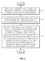
- FIG. 2 is a flowchart illustrating a wireless measuring method using an SAW-based micro sensor according to an embodiment of the present invention.
- FIG. 1 is a configuration view illustrating a wireless measurement device using a surface acoustic wave (SAW)-based micro sensor 10 according to an embodiment of the present invention.
- SAW surface acoustic wave
- the wireless measurement device may include the SAW-based micro sensor 10 and a portable reader 20 .
- the SAW-based micro sensor 10 converts a pulse signal wirelessly received into an SAW, reflects the SAW to measure variances in environmental elements, and generates and wirelessly transmits a plurality of pulse signals.
- the environmental elements may be pressure, a temperature, humidity, etc.
- the SAW-based micro sensor 10 includes a substrate (not shown), an antenna (not shown), an inter-digital transducer (IDT), and a reflector part (not shown) including a plurality of reflectors to measure the variances in the environmental elements.
- the substrate may be formed of a material having piezoelectricity. As an example of the material, LiNbO3, LiTaO3, quartz, etc may be used. Particularly, the substrate may be 41o YX LiNbO3 piezoelectric substrate having high SAW propagation velocity and a great electrochemical coupling element.
- the high SAW speed allows patterning of a device while being manufactured to be easy.
- the great electrochemical coupling element allows high reflectivity from the reflectors and a low insertion loss.
- the antenna wirelessly transmits and receives a pulse signal.
- the antenna may transmit and receive the pulse signal via a communication in a frequency band with an intermediate frequency of 2.4 GHz.
- the IDT generates an SAW by applying the pulse signal received at the antenna to a plurality of metallic electrodes formed parallel to one another and converts a plurality of SAWs reflected by the reflector part into a plurality of pulse signals, and wirelessly outputs the plurality of pulse signals via the antenna.
- the SAW reflected by the reflector part as described above are a plurality thereof because the SAW is reflected by the plurality of reflectors included in the reflector part, respectively. Since the IDT has a single phase unidirectional transducer configuration in such a way that the SAW is not propagated with the IDT centered but is propagated in one direction, thereby minimizing energy of the applied pulse signal.
- the reflector part includes the plurality of reflectors and reflects the SAW generated by the IDT.
- the reader 20 generates and wirelessly transmits a pulse signal to the SAW-based micro sensor 10 to measure variances in environmental elements. Whenever an interval between the plurality of pulse signals received by reflecting the transmitted pulse signal by the SAW micro sensor 10 is corresponding to a determined interval between pulse signals of an environmental element, the reader 20 generates and wirelessly transmits a pulse signal to the SAW-based micro sensor 10 and measures a variance in the environmental element by counting times of pulse signals generated for a certain amount of time.
- the reader 20 includes a radio frequency (RF) part 21 and an environmental element variance measurement part 24 .
- RF radio frequency
- the environmental element variance measurement part 24 generates and transmits a pulse signal for measuring a variance of an environmental element to the SAW-based micro sensor 10 via the RF part 21 . Whenever an interval between the plurality of pulse signals received by reflecting the transmitted pulse signal by the SAW micro sensor 10 is corresponding to a determined interval between pulse signals of an environmental element, the environmental element variance measurement part 24 generates and wirelessly transmits a pulse signal to the SAW-based micro sensor 10 via the RF part 21 and measures a variance in the environmental element by counting times of pulse signals generated for a certain amount of time.
- the RF part 21 wirelessly transmits the pulse signal generated by the environmental element variance measurement part 24 to the SAW-based micro sensor 10 , transmits the plurality of pulse signals wirelessly received from the SAW-based micro sensor 10 to the environmental element variance measurement part 24 , and includes an antenna ANT, a transmitter 22 , a receiver 23 , a frequency synthesizer 25 , a transmission/reception selecting switch (T/R SW) 26 , and a duplexer 27 .
- the antenna ANT wirelessly transmits and receives a pulse signal.
- the frequency synthesizer 25 outputs a signal having a frequency in a certain band.
- the transmitter 22 modulates the pulse signal generated by the environmental element variance measurement part 24 by using the signal outputted by the frequency synthesizer 25 and transmits the modulated signal to the SAW-based micro sensor 10 via the antenna ANT.
- the receiver 23 modulates the plurality of pulse signals reflected by the SAW-based micro sensor 10 and received via the antenna ANT by using the signal outputted by the frequency synthesizer 25 and transmits the modulated signals to the environmental element variance measurement part 24 .
- the T/S selecting switch 26 connects the duplexer 27 and the receiver 24 to each other and transmits a plurality of pulse signals received via the antenna ANT to the receiver 23 by switching according to a certain reception-selecting signal or connects the duplexer 27 and the transmitter 22 to each other and transmits an signal outputted by the transmitter 22 to the antenna ANT by switching according to a certain transmission-selecting signal.
- the certain transmission-selecting signal may be generated the environmental element variance measurement part 24 when transmitting a pulse signal for measuring a variance of the environmental element
- the certain reception-selecting signal is for receiving a pulse signal reflected by the SAW-based micro sensor 10 to measure the variance of the environmental element and may be generated by the environmental element variance measurement part 24 .
- the duplexer 27 is connected to the antenna ANT and distinguishes signals transmitted and received by the RF part 21 . That is, the duplexer 27 may include a band pass filter allowing only a frequency of a transmitted signal to pass and a band pass filter allowing only a frequency of a received signal to pass.
- FIG. 2 is a flowchart illustrating a method of wirelessly measuring by using the SAW-based micro sensor 10 according to an embodiment of the present invention.
- the wirelessly measuring method shown in FIG. 2 may be performed by the wireless measurement device shown in FIG. 1 . Accordingly, based on the configuration shown in FIG. 1 , the method of wirelessly measuring by using the SAW-based micro sensor 10 will now be described.
- the reader 20 to measure a variance of an environmental element, generates a pulse signal and wirelessly transmits the pulse signal to the SAW-based micro sensor 10 (S 1 ).
- the SAW-based micro sensor 10 converts the wirelessly received pulse signal into an SAW and to measure the variance of the environmental element, generates a plurality of pulse signals by reflecting the SAW, and wirelessly transmits the plurality of pulse signals (S 2 ).
- the environmental element may be pressure, a temperature, humidity, etc.
- the reader 20 generates and wirelessly transmits a pulse signal to the SAW-based micro sensor 10 and measures the variance of the environmental element by counting times of pulse signals generated for a certain amount of time whenever an interval between the plurality of pulse signals received by reflecting the transmitted pulse signal by the SAW micro sensor 10 is corresponding to a determined interval between pulse signals of the environmental element (S 3 ).
- the present invention may be applied to the field of wireless measurement devices using micro sensors.
Abstract
Description
Claims (6)
Applications Claiming Priority (3)
| Application Number | Priority Date | Filing Date | Title |
|---|---|---|---|
| KR10-2010-0092034 | 2010-09-17 | ||
| KR1020100092034A KR101202878B1 (en) | 2010-09-17 | 2010-09-17 | Wireless measurement apparatus and method using surface acoustic wave based micro-sensor |
| PCT/KR2011/006775 WO2012036460A2 (en) | 2010-09-17 | 2011-09-14 | Wireless type measurement apparatus using surface acoustic wave-based micro sensor and method thereof |
Publications (2)
| Publication Number | Publication Date |
|---|---|
| US20130174662A1 US20130174662A1 (en) | 2013-07-11 |
| US9116034B2 true US9116034B2 (en) | 2015-08-25 |
Family
ID=45832096
Family Applications (1)
| Application Number | Title | Priority Date | Filing Date |
|---|---|---|---|
| US13/824,005 Active 2032-07-04 US9116034B2 (en) | 2010-09-17 | 2011-09-14 | Wireless measurement device using surface acoustic wave (SAW)-based micro sensor and method of using the saw-based micro sensor |
Country Status (3)
| Country | Link |
|---|---|
| US (1) | US9116034B2 (en) |
| KR (1) | KR101202878B1 (en) |
| WO (1) | WO2012036460A2 (en) |
Families Citing this family (8)
| Publication number | Priority date | Publication date | Assignee | Title |
|---|---|---|---|---|
| KR101371419B1 (en) * | 2013-12-27 | 2014-03-07 | (주)서전기전 | Temperature sensing system using surface acoustic wave temperature sensor |
| KR101396545B1 (en) * | 2013-12-27 | 2014-05-20 | (주)서전기전 | Distribution panel being equipped with sensing system with multile temperature sensor |
| KR102238114B1 (en) * | 2014-07-16 | 2021-04-08 | 아주대학교산학협력단 | Using lithium niobate surface acoustic wave biosensor |
| KR101654367B1 (en) | 2016-02-17 | 2016-09-05 | 지투파워 (주) | Wireless temperature detection system of high voltage distributing board, low voltage distributing board, distributing board, motor control board by detecting surface acoustic wave |
| KR101648803B1 (en) | 2016-02-17 | 2016-08-17 | 삼덕전기 주식회사 | System for temperature detecting in wireless type of high voltage distributing board, low voltage distributing board, distributing board, motor contorl board |
| KR101844806B1 (en) * | 2016-05-17 | 2018-04-03 | 한빛이디에스(주) | wireless temperature measurement device using surface acoustic wave device |
| IT201600079657A1 (en) * | 2016-07-28 | 2018-01-28 | Agenzia Naz Per Le Nuove Tecnologie Lenergia E Lo Sviluppo Economico Sostenibile Enea | DEVICE AND MEASUREMENT SYSTEM |
| KR101831426B1 (en) | 2017-12-06 | 2018-02-22 | (주)서전기전 | The distribution panel having system for measuring a partial discharge and temperature by one sensor |
Citations (24)
| Publication number | Priority date | Publication date | Assignee | Title |
|---|---|---|---|---|
| US4535632A (en) * | 1982-09-29 | 1985-08-20 | Schlumberger Technology Corporation | Surface acoustic wave sensors |
| US20030005759A1 (en) * | 2001-07-09 | 2003-01-09 | Breed David S. | Wireless sensing and communication system of roadways |
| JP2004320319A (en) | 2003-04-15 | 2004-11-11 | Sony Corp | Radio communication system and method therefor, radio communication apparatus and method therefor, and program |
| US6848295B2 (en) * | 2002-04-17 | 2005-02-01 | Wayne State University | Acoustic wave sensor apparatus, method and system using wide bandgap materials |
| JP2005121498A (en) | 2003-10-17 | 2005-05-12 | Sony Corp | Surface acoustic sensing system |
| US20060032290A1 (en) * | 2004-08-12 | 2006-02-16 | Honeywell International, Inc. | Acoustic wave sensor with reduced condensation and recovery time |
| US7017404B1 (en) * | 2002-10-02 | 2006-03-28 | Aron Zev Kain | Wireless system for measuring pressure and flow in tubes |
| US20060075820A1 (en) * | 2004-10-13 | 2006-04-13 | Honeywell International Inc. | MEMS SAW sensor |
| US7040139B2 (en) * | 2003-06-10 | 2006-05-09 | Smiths Detection Inc. | Sensor arrangement |
| US7096736B2 (en) * | 2003-08-04 | 2006-08-29 | The Goodyear Tire & Rubber Company | Passive tire pressure sensor and method |
| US20060230834A1 (en) * | 2005-04-14 | 2006-10-19 | Honeywell International, Inc. | Multiple-mode acoustic wave sensor |
| US20060230833A1 (en) * | 2005-04-14 | 2006-10-19 | Liu James Z | Wireless oil filter sensor |
| US20060243064A1 (en) * | 2005-04-27 | 2006-11-02 | Honeywell International, Inc. | Acoustic wave flow sensor |
| US7146861B1 (en) * | 2005-10-18 | 2006-12-12 | Honeywell International Inc. | Disposable and trimmable wireless pressure sensor |
| US20060283247A1 (en) * | 2005-06-16 | 2006-12-21 | Honeywell International, Inc. | Passive and wireless acoustic wave accelerometer |
| US20060283252A1 (en) * | 2005-06-17 | 2006-12-21 | Honeywell International Inc. | Passive acoustic wave sensor system |
| US20070039371A1 (en) * | 2005-08-12 | 2007-02-22 | Omron Corporation | Frictional characteristic measuring apparatus and tire directed thereto |
| US20070107519A1 (en) * | 2005-11-14 | 2007-05-17 | Honeywell International Inc. | Wireless acoustic wave sensor system for use in vehicle applications |
| US7253725B2 (en) * | 2002-10-03 | 2007-08-07 | Automotive Technologies International, Inc. | Apparatus and method for boosting signals from a signal-generating or modifying device |
| KR20070096217A (en) | 2006-03-21 | 2007-10-02 | 엘지전자 주식회사 | Tag for rfid and fabricating method thereof |
| US20080127729A1 (en) * | 2005-03-25 | 2008-06-05 | Edmonson Peter J | Differentiation and identification of analogous chemical or biological substances with biosensors |
| JP2008204234A (en) | 2007-02-21 | 2008-09-04 | Teruya:Kk | Rfid tag built-in saw (surface acoustic wave) sensor and measurement system |
| US20090193897A1 (en) * | 2008-02-06 | 2009-08-06 | Honeywell International Inc. | Composition for material sensing and related method and apparatus |
| US8960004B2 (en) * | 2010-09-29 | 2015-02-24 | The George Washington University | Synchronous one-pole surface acoustic wave resonator |
-
2010
- 2010-09-17 KR KR1020100092034A patent/KR101202878B1/en active IP Right Grant
-
2011
- 2011-09-14 WO PCT/KR2011/006775 patent/WO2012036460A2/en active Application Filing
- 2011-09-14 US US13/824,005 patent/US9116034B2/en active Active
Patent Citations (25)
| Publication number | Priority date | Publication date | Assignee | Title |
|---|---|---|---|---|
| US4535632A (en) * | 1982-09-29 | 1985-08-20 | Schlumberger Technology Corporation | Surface acoustic wave sensors |
| US20030005759A1 (en) * | 2001-07-09 | 2003-01-09 | Breed David S. | Wireless sensing and communication system of roadways |
| US6848295B2 (en) * | 2002-04-17 | 2005-02-01 | Wayne State University | Acoustic wave sensor apparatus, method and system using wide bandgap materials |
| US7017404B1 (en) * | 2002-10-02 | 2006-03-28 | Aron Zev Kain | Wireless system for measuring pressure and flow in tubes |
| US7253725B2 (en) * | 2002-10-03 | 2007-08-07 | Automotive Technologies International, Inc. | Apparatus and method for boosting signals from a signal-generating or modifying device |
| JP2004320319A (en) | 2003-04-15 | 2004-11-11 | Sony Corp | Radio communication system and method therefor, radio communication apparatus and method therefor, and program |
| US7151437B2 (en) | 2003-04-15 | 2006-12-19 | Sony Corporation | Radio communication system and method, radio communication apparatus and method, and program |
| US7040139B2 (en) * | 2003-06-10 | 2006-05-09 | Smiths Detection Inc. | Sensor arrangement |
| US7096736B2 (en) * | 2003-08-04 | 2006-08-29 | The Goodyear Tire & Rubber Company | Passive tire pressure sensor and method |
| JP2005121498A (en) | 2003-10-17 | 2005-05-12 | Sony Corp | Surface acoustic sensing system |
| US20060032290A1 (en) * | 2004-08-12 | 2006-02-16 | Honeywell International, Inc. | Acoustic wave sensor with reduced condensation and recovery time |
| US20060075820A1 (en) * | 2004-10-13 | 2006-04-13 | Honeywell International Inc. | MEMS SAW sensor |
| US20080127729A1 (en) * | 2005-03-25 | 2008-06-05 | Edmonson Peter J | Differentiation and identification of analogous chemical or biological substances with biosensors |
| US20060230834A1 (en) * | 2005-04-14 | 2006-10-19 | Honeywell International, Inc. | Multiple-mode acoustic wave sensor |
| US20060230833A1 (en) * | 2005-04-14 | 2006-10-19 | Liu James Z | Wireless oil filter sensor |
| US20060243064A1 (en) * | 2005-04-27 | 2006-11-02 | Honeywell International, Inc. | Acoustic wave flow sensor |
| US20060283247A1 (en) * | 2005-06-16 | 2006-12-21 | Honeywell International, Inc. | Passive and wireless acoustic wave accelerometer |
| US20060283252A1 (en) * | 2005-06-17 | 2006-12-21 | Honeywell International Inc. | Passive acoustic wave sensor system |
| US20070039371A1 (en) * | 2005-08-12 | 2007-02-22 | Omron Corporation | Frictional characteristic measuring apparatus and tire directed thereto |
| US7146861B1 (en) * | 2005-10-18 | 2006-12-12 | Honeywell International Inc. | Disposable and trimmable wireless pressure sensor |
| US20070107519A1 (en) * | 2005-11-14 | 2007-05-17 | Honeywell International Inc. | Wireless acoustic wave sensor system for use in vehicle applications |
| KR20070096217A (en) | 2006-03-21 | 2007-10-02 | 엘지전자 주식회사 | Tag for rfid and fabricating method thereof |
| JP2008204234A (en) | 2007-02-21 | 2008-09-04 | Teruya:Kk | Rfid tag built-in saw (surface acoustic wave) sensor and measurement system |
| US20090193897A1 (en) * | 2008-02-06 | 2009-08-06 | Honeywell International Inc. | Composition for material sensing and related method and apparatus |
| US8960004B2 (en) * | 2010-09-29 | 2015-02-24 | The George Washington University | Synchronous one-pole surface acoustic wave resonator |
Non-Patent Citations (1)
| Title |
|---|
| International Search Report (ISR) in PCT/KR2011/006775, dated Mar. 26, 2012, with English Translation. |
Also Published As
| Publication number | Publication date |
|---|---|
| KR20120029906A (en) | 2012-03-27 |
| KR101202878B1 (en) | 2012-11-19 |
| WO2012036460A3 (en) | 2012-05-18 |
| US20130174662A1 (en) | 2013-07-11 |
| WO2012036460A2 (en) | 2012-03-22 |
Similar Documents
| Publication | Publication Date | Title |
|---|---|---|
| US9116034B2 (en) | Wireless measurement device using surface acoustic wave (SAW)-based micro sensor and method of using the saw-based micro sensor | |
| US7434989B2 (en) | SAW temperature sensor and system | |
| US7343804B2 (en) | Wireless acoustic wave sensor system for use in vehicle applications | |
| Schimetta et al. | A wireless pressure-measurement system using a SAW hybrid sensor | |
| Seifert et al. | Mechanical sensors based on surface acoustic waves | |
| US8099048B2 (en) | Wireless communication system using surface acoustic wave (SAW) second harmonic techniques | |
| US20070119257A1 (en) | Vibration detection method and system, battery-less vibration sensor and interrogator therefor | |
| US6810750B1 (en) | Encoded surface acoustic wave based strain sensor | |
| CN103279777A (en) | Wireless surface acoustic wave temperature measurement system reader-writer | |
| KR20030013417A (en) | Method and device for radio determining at least one object position and/or orientation | |
| CN100429479C (en) | Hand-set using sound-wave to measure distance and measuring method therefor | |
| JP2003534561A (en) | Sensor, sensor system and method for remotely detecting a measurand | |
| WO2013150326A1 (en) | Passive wireless microphone | |
| RU2585487C1 (en) | Passive temperature sensor operating on surface acoustic waves | |
| JP2005092490A (en) | Radio remote sensing system using passive saw sensor | |
| US20220173721A1 (en) | Acoustic wave sensor and interrogation of the same | |
| CN111316076B (en) | Measuring device with passive cooperative target | |
| Reindl | Wireless passive sensors: Basic principles and performances | |
| KR100807843B1 (en) | Transmitter for TPMS | |
| CN211783950U (en) | Surface acoustic wave temperature sensor with time division and frequency division combined coding | |
| KR100778651B1 (en) | Tire pressure monitoring system and method for tire pressure monitoring | |
| Seifert et al. | Wirelessly interrogable acoustic sensors | |
| RU2758341C1 (en) | Passive wireless sensor of magnetic field on surface acoustic waves | |
| JP2008292362A (en) | Sensing system | |
| Wei et al. | Surface acoustic wave based radio frequency identification tags |
Legal Events
| Date | Code | Title | Description |
|---|---|---|---|
| AS | Assignment |
Owner name: AJOU UNIVERSITY INDUSTRY COOPERATION FOUNDATION, K Free format text: ASSIGNMENT OF ASSIGNORS INTEREST;ASSIGNORS:YANG, SANG SIK;KIM, YOUNG KIL;PARK, IK MO;AND OTHERS;REEL/FRAME:030017/0650 Effective date: 20130314 |
|
| FEPP | Fee payment procedure |
Free format text: PAYOR NUMBER ASSIGNED (ORIGINAL EVENT CODE: ASPN); ENTITY STATUS OF PATENT OWNER: SMALL ENTITY |
|
| STCF | Information on status: patent grant |
Free format text: PATENTED CASE |
|
| MAFP | Maintenance fee payment |
Free format text: PAYMENT OF MAINTENANCE FEE, 4TH YR, SMALL ENTITY (ORIGINAL EVENT CODE: M2551); ENTITY STATUS OF PATENT OWNER: SMALL ENTITY Year of fee payment: 4 |
|
| MAFP | Maintenance fee payment |
Free format text: PAYMENT OF MAINTENANCE FEE, 8TH YR, SMALL ENTITY (ORIGINAL EVENT CODE: M2552); ENTITY STATUS OF PATENT OWNER: SMALL ENTITY Year of fee payment: 8 |