US9120656B2 - Rope anchor for a winch - Google Patents
Rope anchor for a winch Download PDFInfo
- Publication number
- US9120656B2 US9120656B2 US13/523,476 US201213523476A US9120656B2 US 9120656 B2 US9120656 B2 US 9120656B2 US 201213523476 A US201213523476 A US 201213523476A US 9120656 B2 US9120656 B2 US 9120656B2
- Authority
- US
- United States
- Prior art keywords
- anchor
- slot
- wedge
- cable
- Prior art date
- Legal status (The legal status is an assumption and is not a legal conclusion. Google has not performed a legal analysis and makes no representation as to the accuracy of the status listed.)
- Active
Links
Images


Classifications
-
- B—PERFORMING OPERATIONS; TRANSPORTING
- B66—HOISTING; LIFTING; HAULING
- B66D—CAPSTANS; WINCHES; TACKLES, e.g. PULLEY BLOCKS; HOISTS
- B66D1/00—Rope, cable, or chain winding mechanisms; Capstans
- B66D1/28—Other constructional details
- B66D1/30—Rope, cable, or chain drums or barrels
- B66D1/34—Attachment of ropes or cables to drums or barrels
-
- F—MECHANICAL ENGINEERING; LIGHTING; HEATING; WEAPONS; BLASTING
- F16—ENGINEERING ELEMENTS AND UNITS; GENERAL MEASURES FOR PRODUCING AND MAINTAINING EFFECTIVE FUNCTIONING OF MACHINES OR INSTALLATIONS; THERMAL INSULATION IN GENERAL
- F16G—BELTS, CABLES, OR ROPES, PREDOMINANTLY USED FOR DRIVING PURPOSES; CHAINS; FITTINGS PREDOMINANTLY USED THEREFOR
- F16G11/00—Means for fastening cables or ropes to one another or to other objects; Caps or sleeves for fixing on cables or ropes
- F16G11/04—Means for fastening cables or ropes to one another or to other objects; Caps or sleeves for fixing on cables or ropes with wedging action, e.g. friction clamps
- F16G11/044—Means for fastening cables or ropes to one another or to other objects; Caps or sleeves for fixing on cables or ropes with wedging action, e.g. friction clamps friction clamps deforming the cable, wire, rope or cord
- F16G11/046—Means for fastening cables or ropes to one another or to other objects; Caps or sleeves for fixing on cables or ropes with wedging action, e.g. friction clamps friction clamps deforming the cable, wire, rope or cord by bending the cable around a surface
Definitions
- the present disclosure relates to a winch and more particularly to a rope anchor for a winch that allows for easy removal of the anchor after being set in place by the loading of the winch.
- Winches commonly include a motor for driving a drum on which a cable can be wound or un-wound.
- the motor can be an electric, hydraulic, or a gas powered motor.
- the cable can be a rope, a wire cable, or other type of line or strap. When the cable becomes worn, it can be necessary to change the cable.
- a winch includes a motor and a rotatable drum drivingly attached to the motor.
- the rotatable drum includes an anchor pocket therein.
- a cable includes a proximal end connected to the rotatable drum by an anchor received in said anchor pocket with the cable wrapped around the anchor.
- the anchor includes a first slot in a surface thereof and the rotatable drum includes a second slot therein adjacent to the anchor pocket that allows access to the first slot in the anchor. An edge of the second slot forms a fulcrum point for a pry tool inserted into the first and second slots for freeing the anchor from the anchor pocket.
- FIG. 1 is a perspective view of an exemplary winch according to the principles of the present disclosure
- FIG. 2 is an exploded perspective view of a winch drum, cable, and anchor system according to the principles of the present disclosure
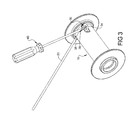
- FIG. 3 is a perspective view of a winch drum/cable assembly illustrating a process for removing the cable anchor from the drum according to the principles of the present disclosure
- FIG. 4 is a perspective view of an anchor according to the principles of the present disclosure.
- Example embodiments are provided so that this disclosure will be thorough, and will fully convey the scope to those who are skilled in the art. Numerous specific details are set forth such as examples of specific components, devices, and methods, to provide a thorough understanding of embodiments of the present disclosure. It will be apparent to those skilled in the art that specific details need not be employed, that example embodiments may be embodied in many different forms and that neither should be construed to limit the scope of the disclosure. In some example embodiments, well-known processes, well-known device structures, and well-known technologies are not described in detail.
- first, second, third, etc. may be used herein to describe various elements, components, regions, layers and/or sections, these elements, components, regions, layers and/or sections should not be limited by these terms. These terms may be only used to distinguish one element, component, region, layer or section from another region, layer or section. Terms such as “first,” “second,” and other numerical terms when used herein do not imply a sequence or order unless clearly indicated by the context. Thus, a first element, component, region, layer or section discussed below could be termed a second element, component, region, layer or section without departing from the teachings of the example embodiments.
- Spatially relative terms such as “inner,” “outer,” “beneath,” “below,” “lower,” “above,” “upper,” and the like, may be used herein for ease of description to describe one element or feature's relationship to another element(s) or feature(s) as illustrated in the figures. Spatially relative terms may be intended to encompass different orientations of the device in use or operation in addition to the orientation depicted in the figures. For example, if the device in the figures is turned over, elements described as “below” or “beneath” other elements or features would then be oriented “above” the other elements or features. Thus, the example term “below” can encompass both an orientation of above and below. The device may be otherwise oriented (rotated 90 degrees or at other orientations) and the spatially relative descriptors used herein interpreted accordingly.
- an exemplary winch 10 includes a motor 12 , a gear train 14 rotatably connected with the motor 12 , and a drum 16 rotatably driven by the motor 12 and gear train 14 .
- the drum 16 can be supported on both ends by a drum support 18 .
- a cable 20 is wound onto the drum 16 and can be spooled out or spooled in for performing various pulling operations.
- the rotatable drum 16 includes an anchor pocket 22 disposed in a cylindrical body 24 thereof.
- the anchor pocket 22 can be wedge-shaped, or other shapes can be used.
- the cable 20 extends through an opening 26 that communicates with the anchor pocket 22 wherein the proximal end of the cable 20 wraps around an anchor 30 that is received within the anchor pocket 22 .
- the anchor 30 can be wedged-shaped, circular, oval, or have other shapes and can include first and second side faces 32 at least one of which can be provided with a slot 34 that can extend through the anchor or can be formed like a divot, recess, pocket, or a raised edge.
- the proximal end of the cable 20 wraps around the anchor 30 and can be clamped to itself and pulled tightly so that the anchor 30 is wedged within the anchor pocket 22 of the rotatable drum 16 .
- the cable drum is provided with a slot 36 that is adjacent to the anchor pocket 22 and communicates with the slot 34 in the anchor 30 when the anchor 30 is inserted into the anchor pocket 22 .
- a pry tool such as a screwdriver 40 can be inserted in the slot 36 of the rotatable drum 16 as well as the slot 34 of the anchor 30 and the inner edge 38 of the slot 36 can be used as a fulcrum point to allow pry tool 40 to pry the anchor 30 out of the anchor pocket 22 so that the cable 20 can be disconnected from the drum to be replaced or repaired.
- the corresponding slots 34 and 36 provided in the anchor 30 and rotatable drum 16 provide easy access for removal of the anchor 30 that has not been available in prior cable anchor systems. It is noted that the winch 10 can be rated at greater than 6,000 pounds and, therefore, the anchor 30 can become tightly wedged within the anchor pocket 22 making its removal very difficult. However, with the improved design of the present disclosure, removal of the anchor 30 from the anchor pocket 22 has been greatly improved.
Abstract
Description
Claims (6)
Priority Applications (6)
| Application Number | Priority Date | Filing Date | Title |
|---|---|---|---|
| US13/523,476 US9120656B2 (en) | 2012-06-14 | 2012-06-14 | Rope anchor for a winch |
| CA2814475A CA2814475C (en) | 2012-06-14 | 2013-04-29 | Rope anchor for a winch |
| AU2013205792A AU2013205792B2 (en) | 2012-06-14 | 2013-05-09 | Rope anchor for a winch |
| DE102013104888A DE102013104888A1 (en) | 2012-06-14 | 2013-05-13 | Rope anchor for a winch |
| FR1354301A FR2991977A1 (en) | 2012-06-14 | 2013-05-14 | CABLE ANCHOR FOR A WINCH |
| CN201310176676.1A CN103508349B (en) | 2012-06-14 | 2013-05-14 | The line anchor of winch |
Applications Claiming Priority (1)
| Application Number | Priority Date | Filing Date | Title |
|---|---|---|---|
| US13/523,476 US9120656B2 (en) | 2012-06-14 | 2012-06-14 | Rope anchor for a winch |
Publications (2)
| Publication Number | Publication Date |
|---|---|
| US20130334479A1 US20130334479A1 (en) | 2013-12-19 |
| US9120656B2 true US9120656B2 (en) | 2015-09-01 |
Family
ID=49668135
Family Applications (1)
| Application Number | Title | Priority Date | Filing Date |
|---|---|---|---|
| US13/523,476 Active US9120656B2 (en) | 2012-06-14 | 2012-06-14 | Rope anchor for a winch |
Country Status (6)
| Country | Link |
|---|---|
| US (1) | US9120656B2 (en) |
| CN (1) | CN103508349B (en) |
| AU (1) | AU2013205792B2 (en) |
| CA (1) | CA2814475C (en) |
| DE (1) | DE102013104888A1 (en) |
| FR (1) | FR2991977A1 (en) |
Cited By (11)
| Publication number | Priority date | Publication date | Assignee | Title |
|---|---|---|---|---|
| US20150097065A1 (en) * | 2013-10-03 | 2015-04-09 | C-Tech Oil Well Technologies Inc. | Coiled rod reel |
| US20160251822A1 (en) * | 2015-02-27 | 2016-09-01 | Caterpillar Global Mining America Llc | Hoist drum for power shovel |
| USD807731S1 (en) | 2016-10-28 | 2018-01-16 | Warn Industries, Inc. | Fairlead |
| USD807732S1 (en) | 2016-10-28 | 2018-01-16 | Warn Industries, Inc. | Fairlead |
| USD807733S1 (en) | 2016-10-28 | 2018-01-16 | Warn Industries, Inc. | Lighted fairlead |
| USD811685S1 (en) | 2016-10-28 | 2018-02-27 | Warn Industries, Inc. | Clutch lever of a winch |
| USD811684S1 (en) | 2016-10-28 | 2018-02-27 | Warn Industries, Inc. | Control pack of a winch |
| US10112808B2 (en) * | 2012-06-29 | 2018-10-30 | Warn Industries, Inc. | Winch |
| US20190248632A1 (en) * | 2018-02-12 | 2019-08-15 | David R. Hall | Wedge-Style Line Clamp |
| US11708250B2 (en) * | 2020-01-22 | 2023-07-25 | Caterpillar Inc. | Retention system for a line on a spool |
| US11772942B1 (en) * | 2019-07-26 | 2023-10-03 | Automatic Devices Company | Modular lift system |
Families Citing this family (6)
| Publication number | Priority date | Publication date | Assignee | Title |
|---|---|---|---|---|
| CN103010990B (en) * | 2012-12-03 | 2015-04-15 | 浙江双友物流器械股份有限公司 | Belt axle connecting piece of winch and manufacturing method |
| US9067250B2 (en) * | 2012-12-20 | 2015-06-30 | Solar Turbines Incorporated | Portable tube coiler |
| USD744189S1 (en) * | 2014-08-20 | 2015-11-24 | Warn Industries, Inc. | Winch |
| USD742614S1 (en) | 2014-11-04 | 2015-11-03 | Engo Industries, L.L.C. | Winch |
| US10589967B2 (en) * | 2018-05-03 | 2020-03-17 | Magnetic Field Effects, LLC | Drum assembly adapted to accommodate wire access lines of varying diameters |
| US10577230B1 (en) | 2018-10-22 | 2020-03-03 | Gary Shelton | Winch device |
Citations (45)
| Publication number | Priority date | Publication date | Assignee | Title |
|---|---|---|---|---|
| US424388A (en) * | 1890-03-25 | Rope-clam p | ||
| US1369842A (en) * | 1919-01-10 | 1921-03-01 | Harry C Schaffernocker | Cable-clamp |
| US1380800A (en) * | 1921-06-07 | Worth | ||
| US1555544A (en) * | 1924-06-05 | 1925-09-29 | Anthony Co | Spool |
| US1859561A (en) | 1929-06-08 | 1932-05-24 | Union Trust Co | Cable or wire clamp |
| USRE18789E (en) * | 1933-04-04 | Cathead | ||
| US1913508A (en) * | 1929-08-03 | 1933-06-13 | Phillips James Le Roy | Cable anchoring means for drums |
| US2053976A (en) * | 1933-03-01 | 1936-09-08 | Columbus Mckinnon Chain Compan | Detent means for cable drums |
| US2085333A (en) | 1936-03-13 | 1937-06-29 | Nazro H Reynolds | Rope socket |
| US2314733A (en) * | 1938-04-15 | 1943-03-23 | Frank M Owen | Automatic cathead |
| US2329943A (en) * | 1941-06-12 | 1943-09-21 | Columbus Mckinnon Chain Corp | Means for securing cables to hoist drums |
| US2420594A (en) * | 1945-11-15 | 1947-05-13 | Delmar F Reeves | Cable anchor for winches |
| US2540887A (en) * | 1948-12-31 | 1951-02-06 | Auld D L Co | Cable-anchoring and -tightening device |
| US2827680A (en) * | 1955-07-21 | 1958-03-25 | Gibson Jack | Wedge-eye cable anchoring devices |
| US3582011A (en) | 1969-04-16 | 1971-06-01 | Gearmatic Co Ltd | Quick release drum cable anchor |
| US3654672A (en) * | 1969-02-17 | 1972-04-11 | Ivan R Bullar | Wedge clamping device for cable |
| US3905711A (en) | 1974-10-31 | 1975-09-16 | Marion Power Shovel Co | Cable connecting assembly |
| US4313243A (en) * | 1979-04-12 | 1982-02-02 | Childress Ray R | Sliding wedge cable clamp |
| US4362288A (en) | 1980-06-27 | 1982-12-07 | Herman Allen | Shock-absorbing cable anchor for mobile equipment |
| US4534522A (en) * | 1984-10-18 | 1985-08-13 | Spence Robert L | Spool retaining device |
| US4614007A (en) * | 1984-10-02 | 1986-09-30 | Britax (Wingard) Limited | Clamping means for a strap |
| US5199137A (en) * | 1991-03-25 | 1993-04-06 | Nylube Products, Co. | Rope guard assembly for wedge clamp |
| US5336846A (en) | 1992-06-09 | 1994-08-09 | Isaac Sachs | Cable clamp having loop-forming wedge |
| US5388480A (en) * | 1993-08-04 | 1995-02-14 | Barrett Technology, Inc. | Pretensioning mechanism for tension element drive systems |
| US5553360A (en) * | 1995-05-19 | 1996-09-10 | The Crosby Group, Inc. | Extended wedge socket assembly |
| US5639043A (en) * | 1995-10-27 | 1997-06-17 | Baird; Terry Alexander | Despooled filament tension control device |
| WO1997036123A1 (en) | 1996-03-23 | 1997-10-02 | Gripple Limited | Devices for clamping wires, etc. |
| US5779226A (en) * | 1996-03-15 | 1998-07-14 | Wudtke; Donald J. | Anchoring system |
| JPH10245194A (en) | 1997-03-04 | 1998-09-14 | Sumitomo Constr Mach Co Ltd | Rope terminal end fixing mechanism |
| US5988929A (en) | 1996-10-09 | 1999-11-23 | Columbia Steel Casting Co. | Easy-out cable socket wedge and method for use thereof |
| US5988095A (en) * | 1998-04-22 | 1999-11-23 | Harnischfeger Technologies, Inc. | Clamping mechanism for securing a rope to a winch drum |
| US6058575A (en) * | 1999-06-07 | 2000-05-09 | Dagan; Gideon | Cable clamp |
| JP2001129031A (en) | 1999-11-02 | 2001-05-15 | Meidensha Corp | Electric lift for care |
| US20020104918A1 (en) * | 2001-02-07 | 2002-08-08 | Karl Zacharias | Detachable securement of a cable to a cable drum |
| JP3333769B2 (en) | 2000-01-28 | 2002-10-15 | 住友重機械建機クレーン株式会社 | Winch for construction machinery |
| JP2004035125A (en) | 2002-07-01 | 2004-02-05 | Hitachi Home & Life Solutions Inc | Wire rope terminal attaching device |
| USD489157S1 (en) * | 2002-07-03 | 2004-04-27 | Warn Industries, Inc. | Mid-range vehicle winch |
| US6854164B2 (en) * | 2003-01-28 | 2005-02-15 | Thyssen Elevator Capital Corp | Termination device for an aramid-based elevator rope |
| US6898827B1 (en) * | 2003-08-06 | 2005-05-31 | The Crosby Group, Inc. | Wedge socket with actuator assembly |
| US6981670B2 (en) * | 2003-04-15 | 2006-01-03 | Great Stuff, Inc | Reel having apparatus for improved connection of linear material |
| US7108248B2 (en) * | 2003-10-30 | 2006-09-19 | Demag Cranes & Components Gmbh | Cable pulley block having detachable fastening of a cable to a cable drum |
| US7513452B2 (en) * | 2004-04-06 | 2009-04-07 | Zhejiang Topsun Control Co., Ltd. | Winding, securing and positioning mechanism for a come-along |
| CN101844733A (en) | 2010-05-27 | 2010-09-29 | 浙江诺和机电有限公司 | Electric winch |
| CN201729616U (en) | 2010-07-16 | 2011-02-02 | 梁云清 | Tail-end fixed structure of hoist rope |
| DE102009054226B3 (en) | 2009-11-21 | 2011-02-24 | Demag Cranes & Components Gmbh | Basic frame of a hoist, in particular cable, with connection options |
Family Cites Families (3)
| Publication number | Priority date | Publication date | Assignee | Title |
|---|---|---|---|---|
| FR1557761A (en) * | 1967-12-04 | 1969-02-21 | ||
| JPH0480198A (en) * | 1990-07-24 | 1992-03-13 | Toyota Autom Loom Works Ltd | Fitting construction for wire rope |
| CN2734717Y (en) * | 2004-09-17 | 2005-10-19 | 臧沛江 | Clamping device for wire rope for drum |
-
2012
- 2012-06-14 US US13/523,476 patent/US9120656B2/en active Active
-
2013
- 2013-04-29 CA CA2814475A patent/CA2814475C/en active Active
- 2013-05-09 AU AU2013205792A patent/AU2013205792B2/en active Active
- 2013-05-13 DE DE102013104888A patent/DE102013104888A1/en not_active Ceased
- 2013-05-14 CN CN201310176676.1A patent/CN103508349B/en active Active
- 2013-05-14 FR FR1354301A patent/FR2991977A1/en not_active Withdrawn
Patent Citations (47)
| Publication number | Priority date | Publication date | Assignee | Title |
|---|---|---|---|---|
| US424388A (en) * | 1890-03-25 | Rope-clam p | ||
| US1380800A (en) * | 1921-06-07 | Worth | ||
| USRE18789E (en) * | 1933-04-04 | Cathead | ||
| US1369842A (en) * | 1919-01-10 | 1921-03-01 | Harry C Schaffernocker | Cable-clamp |
| US1555544A (en) * | 1924-06-05 | 1925-09-29 | Anthony Co | Spool |
| US1859561A (en) | 1929-06-08 | 1932-05-24 | Union Trust Co | Cable or wire clamp |
| US1913508A (en) * | 1929-08-03 | 1933-06-13 | Phillips James Le Roy | Cable anchoring means for drums |
| US2053976A (en) * | 1933-03-01 | 1936-09-08 | Columbus Mckinnon Chain Compan | Detent means for cable drums |
| US2085333A (en) | 1936-03-13 | 1937-06-29 | Nazro H Reynolds | Rope socket |
| US2314733A (en) * | 1938-04-15 | 1943-03-23 | Frank M Owen | Automatic cathead |
| US2329943A (en) * | 1941-06-12 | 1943-09-21 | Columbus Mckinnon Chain Corp | Means for securing cables to hoist drums |
| US2420594A (en) * | 1945-11-15 | 1947-05-13 | Delmar F Reeves | Cable anchor for winches |
| US2540887A (en) * | 1948-12-31 | 1951-02-06 | Auld D L Co | Cable-anchoring and -tightening device |
| US2827680A (en) * | 1955-07-21 | 1958-03-25 | Gibson Jack | Wedge-eye cable anchoring devices |
| US3654672A (en) * | 1969-02-17 | 1972-04-11 | Ivan R Bullar | Wedge clamping device for cable |
| US3582011A (en) | 1969-04-16 | 1971-06-01 | Gearmatic Co Ltd | Quick release drum cable anchor |
| US3905711A (en) | 1974-10-31 | 1975-09-16 | Marion Power Shovel Co | Cable connecting assembly |
| US4313243A (en) * | 1979-04-12 | 1982-02-02 | Childress Ray R | Sliding wedge cable clamp |
| US4362288A (en) | 1980-06-27 | 1982-12-07 | Herman Allen | Shock-absorbing cable anchor for mobile equipment |
| US4614007A (en) * | 1984-10-02 | 1986-09-30 | Britax (Wingard) Limited | Clamping means for a strap |
| US4534522A (en) * | 1984-10-18 | 1985-08-13 | Spence Robert L | Spool retaining device |
| US5199137A (en) * | 1991-03-25 | 1993-04-06 | Nylube Products, Co. | Rope guard assembly for wedge clamp |
| US5336846A (en) | 1992-06-09 | 1994-08-09 | Isaac Sachs | Cable clamp having loop-forming wedge |
| US5388480A (en) * | 1993-08-04 | 1995-02-14 | Barrett Technology, Inc. | Pretensioning mechanism for tension element drive systems |
| US5553360A (en) * | 1995-05-19 | 1996-09-10 | The Crosby Group, Inc. | Extended wedge socket assembly |
| US5639043A (en) * | 1995-10-27 | 1997-06-17 | Baird; Terry Alexander | Despooled filament tension control device |
| US5779226A (en) * | 1996-03-15 | 1998-07-14 | Wudtke; Donald J. | Anchoring system |
| WO1997036123A1 (en) | 1996-03-23 | 1997-10-02 | Gripple Limited | Devices for clamping wires, etc. |
| US5988929A (en) | 1996-10-09 | 1999-11-23 | Columbia Steel Casting Co. | Easy-out cable socket wedge and method for use thereof |
| JPH10245194A (en) | 1997-03-04 | 1998-09-14 | Sumitomo Constr Mach Co Ltd | Rope terminal end fixing mechanism |
| US5988095A (en) * | 1998-04-22 | 1999-11-23 | Harnischfeger Technologies, Inc. | Clamping mechanism for securing a rope to a winch drum |
| US6058575A (en) * | 1999-06-07 | 2000-05-09 | Dagan; Gideon | Cable clamp |
| JP2001129031A (en) | 1999-11-02 | 2001-05-15 | Meidensha Corp | Electric lift for care |
| JP3333769B2 (en) | 2000-01-28 | 2002-10-15 | 住友重機械建機クレーン株式会社 | Winch for construction machinery |
| US20020104918A1 (en) * | 2001-02-07 | 2002-08-08 | Karl Zacharias | Detachable securement of a cable to a cable drum |
| JP2004035125A (en) | 2002-07-01 | 2004-02-05 | Hitachi Home & Life Solutions Inc | Wire rope terminal attaching device |
| USD489157S1 (en) * | 2002-07-03 | 2004-04-27 | Warn Industries, Inc. | Mid-range vehicle winch |
| US6854164B2 (en) * | 2003-01-28 | 2005-02-15 | Thyssen Elevator Capital Corp | Termination device for an aramid-based elevator rope |
| US6981670B2 (en) * | 2003-04-15 | 2006-01-03 | Great Stuff, Inc | Reel having apparatus for improved connection of linear material |
| US6898827B1 (en) * | 2003-08-06 | 2005-05-31 | The Crosby Group, Inc. | Wedge socket with actuator assembly |
| US7108248B2 (en) * | 2003-10-30 | 2006-09-19 | Demag Cranes & Components Gmbh | Cable pulley block having detachable fastening of a cable to a cable drum |
| US7513452B2 (en) * | 2004-04-06 | 2009-04-07 | Zhejiang Topsun Control Co., Ltd. | Winding, securing and positioning mechanism for a come-along |
| US8079570B2 (en) * | 2004-04-06 | 2011-12-20 | Zhejiang Topsun Logistic Control Co., Ltd | Winding, securing and positioning mechanism for a come-along |
| DE102009054226B3 (en) | 2009-11-21 | 2011-02-24 | Demag Cranes & Components Gmbh | Basic frame of a hoist, in particular cable, with connection options |
| US8763992B2 (en) | 2009-11-21 | 2014-07-01 | Demag Cranes & Components Gmbh | Base frame for a lifting apparatus having removable support members |
| CN101844733A (en) | 2010-05-27 | 2010-09-29 | 浙江诺和机电有限公司 | Electric winch |
| CN201729616U (en) | 2010-07-16 | 2011-02-02 | 梁云清 | Tail-end fixed structure of hoist rope |
Non-Patent Citations (1)
| Title |
|---|
| Canadian Intellectual Property Office, Office Action of Canadian Patent Application No. 2814475, Mar. 3, 2014, 3 pages. |
Cited By (15)
| Publication number | Priority date | Publication date | Assignee | Title |
|---|---|---|---|---|
| US10618783B2 (en) * | 2012-06-29 | 2020-04-14 | Warn Industries, Inc. | Winch |
| US10370227B2 (en) * | 2012-06-29 | 2019-08-06 | Warn Industries, Inc. | Winch |
| US10112808B2 (en) * | 2012-06-29 | 2018-10-30 | Warn Industries, Inc. | Winch |
| US20150097065A1 (en) * | 2013-10-03 | 2015-04-09 | C-Tech Oil Well Technologies Inc. | Coiled rod reel |
| US20160251822A1 (en) * | 2015-02-27 | 2016-09-01 | Caterpillar Global Mining America Llc | Hoist drum for power shovel |
| US10538896B2 (en) * | 2015-02-27 | 2020-01-21 | Caterpillar Global Mining Llc | Hoist drum for power shovel |
| USD811684S1 (en) | 2016-10-28 | 2018-02-27 | Warn Industries, Inc. | Control pack of a winch |
| USD811685S1 (en) | 2016-10-28 | 2018-02-27 | Warn Industries, Inc. | Clutch lever of a winch |
| USD807733S1 (en) | 2016-10-28 | 2018-01-16 | Warn Industries, Inc. | Lighted fairlead |
| USD807732S1 (en) | 2016-10-28 | 2018-01-16 | Warn Industries, Inc. | Fairlead |
| USD807731S1 (en) | 2016-10-28 | 2018-01-16 | Warn Industries, Inc. | Fairlead |
| US20190248632A1 (en) * | 2018-02-12 | 2019-08-15 | David R. Hall | Wedge-Style Line Clamp |
| US10807842B2 (en) * | 2018-02-12 | 2020-10-20 | Hall Labs Llc | Wedge-style line clamp |
| US11772942B1 (en) * | 2019-07-26 | 2023-10-03 | Automatic Devices Company | Modular lift system |
| US11708250B2 (en) * | 2020-01-22 | 2023-07-25 | Caterpillar Inc. | Retention system for a line on a spool |
Also Published As
| Publication number | Publication date |
|---|---|
| DE102013104888A1 (en) | 2013-12-19 |
| CN103508349B (en) | 2018-08-21 |
| CA2814475C (en) | 2016-06-14 |
| AU2013205792B2 (en) | 2015-09-24 |
| US20130334479A1 (en) | 2013-12-19 |
| AU2013205792A1 (en) | 2014-01-16 |
| CA2814475A1 (en) | 2013-12-14 |
| FR2991977A1 (en) | 2013-12-20 |
| CN103508349A (en) | 2014-01-15 |
Similar Documents
| Publication | Publication Date | Title |
|---|---|---|
| US9120656B2 (en) | Rope anchor for a winch | |
| US8292267B2 (en) | Device for gripping and installing wire | |
| US9604826B2 (en) | Low profile roller fairlead | |
| GB2455972A (en) | A tape disconnect link | |
| CN103797672A (en) | Cable retaining apparatus | |
| EP3356698B1 (en) | Shackle pin split nut assembly | |
| WO2011142823A2 (en) | Detachable ears rope thimble | |
| US8607417B2 (en) | Synthetic rope socket | |
| CN205283048U (en) | Pretwisted suspension wire clip | |
| CN204809819U (en) | Ware is prevented drawing by cable pencil | |
| US10112809B2 (en) | Reliable spooling for a motorized lifting/pulling device | |
| KR100783437B1 (en) | Towing hook apparatus | |
| KR101169933B1 (en) | Cable guide unit | |
| JP4745402B2 (en) | Copper cable removal jig | |
| CN204096776U (en) | A kind of wire harness collating unit | |
| CN204401478U (en) | A kind of suspension cable cutting fastening devices | |
| CN107181204B (en) | Electrification in high voltage stringing protector | |
| CN200988749Y (en) | Anti-clip anti-slip rope external shell for steel rope electric hoist | |
| JP2005231852A (en) | Winding drum of winch | |
| CN101585337B (en) | Winch band shaft | |
| CN104401814A (en) | Cable reel with climbing device | |
| CN203548707U (en) | Soft rope middle wall pulley | |
| CN204717149U (en) | A kind of core of a cable is anti-draws device | |
| CN202586245U (en) | Cable coiling apparatus | |
| KR200447183Y1 (en) | Sleeve and fishing epipment using the same |
Legal Events
| Date | Code | Title | Description |
|---|---|---|---|
| AS | Assignment |
Owner name: WARN INDUSTRIES, INC., OREGON Free format text: ASSIGNMENT OF ASSIGNORS INTEREST;ASSIGNOR:YODER, BRYAN;REEL/FRAME:028378/0069 Effective date: 20120612 |
|
| STCF | Information on status: patent grant |
Free format text: PATENTED CASE |
|
| MAFP | Maintenance fee payment |
Free format text: PAYMENT OF MAINTENANCE FEE, 4TH YEAR, LARGE ENTITY (ORIGINAL EVENT CODE: M1551); ENTITY STATUS OF PATENT OWNER: LARGE ENTITY Year of fee payment: 4 |
|
| MAFP | Maintenance fee payment |
Free format text: PAYMENT OF MAINTENANCE FEE, 8TH YEAR, LARGE ENTITY (ORIGINAL EVENT CODE: M1552); ENTITY STATUS OF PATENT OWNER: LARGE ENTITY Year of fee payment: 8 |