US9154357B2 - Multiple-input multiple-output (MIMO) low noise amplifiers for carrier aggregation - Google Patents
Multiple-input multiple-output (MIMO) low noise amplifiers for carrier aggregation Download PDFInfo
- Publication number
- US9154357B2 US9154357B2 US13/593,764 US201213593764A US9154357B2 US 9154357 B2 US9154357 B2 US 9154357B2 US 201213593764 A US201213593764 A US 201213593764A US 9154357 B2 US9154357 B2 US 9154357B2
- Authority
- US
- United States
- Prior art keywords
- signal
- signals
- gain
- circuits
- drive
- Prior art date
- Legal status (The legal status is an assumption and is not a legal conclusion. Google has not performed a legal analysis and makes no representation as to the accuracy of the status listed.)
- Active
Links
Images


Classifications
-
- H—ELECTRICITY
- H03—ELECTRONIC CIRCUITRY
- H03F—AMPLIFIERS
- H03F3/00—Amplifiers with only discharge tubes or only semiconductor devices as amplifying elements
- H03F3/20—Power amplifiers, e.g. Class B amplifiers, Class C amplifiers
- H03F3/21—Power amplifiers, e.g. Class B amplifiers, Class C amplifiers with semiconductor devices only
- H03F3/211—Power amplifiers, e.g. Class B amplifiers, Class C amplifiers with semiconductor devices only using a combination of several amplifiers
-
- H—ELECTRICITY
- H03—ELECTRONIC CIRCUITRY
- H03F—AMPLIFIERS
- H03F1/00—Details of amplifiers with only discharge tubes, only semiconductor devices or only unspecified devices as amplifying elements
- H03F1/08—Modifications of amplifiers to reduce detrimental influences of internal impedances of amplifying elements
- H03F1/22—Modifications of amplifiers to reduce detrimental influences of internal impedances of amplifying elements by use of cascode coupling, i.e. earthed cathode or emitter stage followed by earthed grid or base stage respectively
- H03F1/223—Modifications of amplifiers to reduce detrimental influences of internal impedances of amplifying elements by use of cascode coupling, i.e. earthed cathode or emitter stage followed by earthed grid or base stage respectively with MOSFET's
-
- H—ELECTRICITY
- H03—ELECTRONIC CIRCUITRY
- H03F—AMPLIFIERS
- H03F3/00—Amplifiers with only discharge tubes or only semiconductor devices as amplifying elements
- H03F3/189—High frequency amplifiers, e.g. radio frequency amplifiers
- H03F3/19—High frequency amplifiers, e.g. radio frequency amplifiers with semiconductor devices only
- H03F3/193—High frequency amplifiers, e.g. radio frequency amplifiers with semiconductor devices only with field-effect devices
-
- H—ELECTRICITY
- H03—ELECTRONIC CIRCUITRY
- H03F—AMPLIFIERS
- H03F3/00—Amplifiers with only discharge tubes or only semiconductor devices as amplifying elements
- H03F3/68—Combinations of amplifiers, e.g. multi-channel amplifiers for stereophonics
-
- H—ELECTRICITY
- H03—ELECTRONIC CIRCUITRY
- H03F—AMPLIFIERS
- H03F3/00—Amplifiers with only discharge tubes or only semiconductor devices as amplifying elements
- H03F3/72—Gated amplifiers, i.e. amplifiers which are rendered operative or inoperative by means of a control signal
-
- H—ELECTRICITY
- H03—ELECTRONIC CIRCUITRY
- H03G—CONTROL OF AMPLIFICATION
- H03G3/00—Gain control in amplifiers or frequency changers without distortion of the input signal
- H03G3/20—Automatic control
-
- H—ELECTRICITY
- H04—ELECTRIC COMMUNICATION TECHNIQUE
- H04L—TRANSMISSION OF DIGITAL INFORMATION, e.g. TELEGRAPHIC COMMUNICATION
- H04L27/00—Modulated-carrier systems
- H04L27/26—Systems using multi-frequency codes
- H04L27/2601—Multicarrier modulation systems
- H04L27/2647—Arrangements specific to the receiver only
-
- H—ELECTRICITY
- H03—ELECTRONIC CIRCUITRY
- H03F—AMPLIFIERS
- H03F2200/00—Indexing scheme relating to amplifiers
- H03F2200/451—Indexing scheme relating to amplifiers the amplifier being a radio frequency amplifier
Definitions
- the present disclosure relates generally to electronics, and more specifically to low noise amplifiers (LNAs).
- LNAs low noise amplifiers
- a wireless device in a wireless communication system may transmit and receive data for two-way communication.
- the wireless device may include a transmitter for data transmission and a receiver for data reception.
- the transmitter may modulate a radio frequency (RF) carrier signal with data to obtain a modulated RF signal, amplify the modulated RF signal to obtain an amplified RF signal having the proper output power level, and transmit the amplified RF signal via an antenna to a base station.
- the receiver may obtain a received RF signal via the antenna and may amplify and process the received RF signal to recover data sent by the base station.
- RF radio frequency
- a wireless device may support carrier aggregation, which is simultaneous operation on multiple carriers.
- a carrier may refer to a range of frequencies used for communication and may be associated with certain characteristics. For example, a carrier may be associated with system information describing operation on the carrier.
- a carrier may also be referred to as a component carrier (CC), a frequency channel, a cell, etc. It is desirable to efficiently support carrier aggregation by the wireless device.
- CC component carrier
- FIG. 1 shows a wireless device communicating with a wireless system.
- FIGS. 2A to 2D show four examples of carrier aggregation (CA).
- FIG. 3 shows a block diagram of the wireless device in FIG. 1 .
- FIG. 4 shows a receiver with a multiple-input multiple-output (MIMO) LNA supporting carrier aggregation.
- MIMO multiple-input multiple-output
- FIG. 5 shows a block diagram of the MIMO LNA in FIG. 4 .
- FIG. 6 shows a schematic diagram of a 2 ⁇ 2 MIMO LNA.
- FIGS. 7A , 7 B and 7 C show operation of the 2 ⁇ 2 MIMO LNA in FIG. 6 in a single-output mode, an intra-band CA mode, and an inter-band CA mode, respectively.
- FIGS. 8A to 8D show four exemplary designs of a 4 ⁇ 2 MIMO LNA.
- FIGS. 9A and 9B show two exemplary designs of an N ⁇ M MIMO LNA.
- FIG. 10 shows an exemplary design of a low-gain circuit for a MIMO LNA.
- FIG. 11 shows a process for performing signal amplification.
- MIMO LNAs having multiple inputs and multiple outputs and supporting carrier aggregation are disclosed herein. These MIMO LNAs may be used for various types of electronic devices such as wireless communication devices.
- FIG. 1 shows a wireless device 110 communicating with a wireless communication system 120 .
- Wireless system 120 may be a Long Term Evolution (LTE) system, a Code Division Multiple Access (CDMA) system, a Global System for Mobile Communications (GSM) system, a wireless local area network (WLAN) system, or some other wireless system.
- LTE Long Term Evolution
- CDMA Code Division Multiple Access
- GSM Global System for Mobile Communications
- WLAN wireless local area network
- a CDMA system may implement Wideband CDMA (WCDMA), cdma2000, or some other version of CDMA.
- FIG. 1 shows wireless system 120 including two base stations 130 and 132 and one system controller 140 .
- a wireless system may include any number of base stations and any set of network entities.
- Wireless device 110 may also be referred to as a user equipment (UE), a mobile station, a terminal, an access terminal, a subscriber unit, a station, etc.
- Wireless device 110 may be a cellular phone, a smartphone, a tablet, a wireless modem, a personal digital assistant (PDA), a handheld device, a laptop computer, a smartbook, a netbook, a cordless phone, a wireless local loop (WLL) station, a Bluetooth device, etc.
- Wireless device 110 may be capable of communicating with wireless system 120 .
- Wireless device 110 may also be capable of receiving signals from broadcast stations (e.g., a broadcast station 134 ), signals from satellites (e.g., a satellite 150 ) in one or more global navigation satellite systems (GNSS), etc.
- Wireless device 110 may support one or more radio technologies for wireless communication such as LTE, cdma2000, WCDMA, GSM, 802.11, etc.
- Wireless device 110 may support carrier aggregation, which is operation on multiple carriers. Carrier aggregation may also be referred to as multi-carrier operation. Wireless device 110 may be able to operate in low-band from 698 to 960 megahertz (MHz), mid-band from 1475 to 2170 MHz, and/or high-band from 2300 to 2690 and 3400 to 3800 MHz. Low-band, mid-band, and high-band refer to three groups of bands (or band groups), with each band group including a number of frequency bands (or simply, “bands”). Each band may cover up to 200 MHz and may include one or more carriers. Each carrier may cover up to 20 MHz in LTE. LTE Release 11 supports 35 bands, which are referred to as LTE/UMTS bands and are listed in 3GPP TS 36.101. Wireless device 110 may be configured with up to 5 carriers in one or two bands in LTE Release 11.
- carrier aggregation may be categorized into two types—intra-band CA and inter-band CA.
- Intra-band CA refers to operation on multiple carriers within the same band.
- Inter-band CA refers to operation on multiple carriers in different bands.
- FIG. 2A shows an example of contiguous intra-band CA.
- wireless device 110 is configured with four contiguous carriers in the same band, which is a band in low-band. Wireless device 110 may receive transmissions on multiple contiguous carriers within the same band.
- FIG. 2B shows an example of non-contiguous intra-band CA.
- wireless device 110 is configured with four non-contiguous carriers in the same band, which is a band in low-band.
- the carriers may be separated by 5 MHz, 10 MHz, or some other amount.
- Wireless device 110 may receive transmissions on multiple non-contiguous carriers within the same band.
- FIG. 2C shows an example of inter-band CA in the same band group.
- wireless device 110 is configured with four carriers in two bands in the same band group, which is low-band.
- Wireless device 110 may receive transmissions on multiple carriers in different bands in the same band group (e.g., low-band in FIG. 2C ).
- FIG. 2D shows an example of inter-band CA in different band groups.
- wireless device 110 is configured with four carriers in two bands in different band groups, which include two carriers in one band in low-band and two additional carriers in another band in mid-band.
- Wireless device 110 may receive transmissions on multiple carriers in different bands in different band groups (e.g., low-band and mid-band in FIG. 2D ).
- FIGS. 2A to 2D show four examples of carrier aggregation.
- Carrier aggregation may also be supported for other combinations of bands and band groups.
- carrier aggregation may be supported for low-band and high-band, mid-band and high-band, high-band and high-band, etc.
- FIG. 3 shows a block diagram of an exemplary design of wireless device 110 in FIG. 1 .
- wireless device 110 includes a transceiver 320 coupled to a primary antenna 310 , receivers 322 coupled to a secondary antenna 312 , and a data processor/controller 380 .
- Transceiver 320 includes multiple (K) receivers 330 aa to 330 ak and multiple (K) transmitters 360 a to 360 k to support multiple bands, carrier aggregation, multiple radio technologies, etc.
- Receivers 322 include multiple (M) receivers 330 ba to 330 bm to support multiple bands, carrier aggregation, multiple radio technologies, receive diversity, MIMO transmission from multiple transmit antennas to multiple receive antennas, etc.
- each receiver 330 includes input circuits 332 , an LNA 340 , and receive circuits 342 .
- antenna 310 receives signals from base stations and/or other transmitter stations and provides a received RF signal, which is routed through an antenna interface circuit 324 and provided to a selected receiver.
- Antenna interface circuit 324 may include switches, duplexers, transmit filters, receive filters, etc. The description below assumes that receiver 330 aa is the selected receiver.
- the received RF signal is passed through input circuits 332 aa , which provides an input RF signal to an LNA 340 aa .
- Input circuits 332 aa may include a matching circuit, a receive filter, etc.
- LNA 340 aa amplifies the input RF signal and provides an output RF signal.
- Receive circuits 342 aa amplify, filter, and downconvert the output RF signal from RF to baseband and provide an analog input signal to data processor 380 .
- Receive circuits 332 aa may include mixers, filters, amplifiers, matching circuits, an oscillator, a local oscillator (LO) generator, a phase locked loop (PLL), etc.
- LO local oscillator
- PLL phase locked loop
- each transmitter 360 includes transmit circuits 362 , a power amplifier (PA) 364 , and output circuits 366 .
- data processor 380 processes (e.g., encodes and modulates) data to be transmitted and provides an analog output signal to a selected transmitter.
- transmitter 360 a is the selected transmitter.
- transmit circuits 362 a amplify, filter, and upconvert the analog output signal from baseband to RF and provide a modulated RF signal.
- Transmit circuits 362 a may include amplifiers, filters, mixers, matching circuits, an oscillator, an LO generator, a PLL, etc.
- a PA 364 a receives and amplifies the modulated RF signal and provides a transmit RF signal having the proper output power level.
- the transmit RF signal is passed through output circuits 366 a , routed through antenna interface circuit 324 , and transmitted via antenna 310 .
- Output circuits 366 a may include a matching circuit, a transmit filter, a directional coupler, etc.
- FIG. 3 shows an exemplary design of receivers 330 and transmitters 360 .
- a receiver and a transmitter may also include other circuits not shown in FIG. 3 , such as filters, matching circuits, etc.
- All or a portion of transceiver 320 and receivers 322 may be implemented on one or more analog integrated circuits (ICs), RF ICs (RFICs), mixed-signal ICs, etc.
- ICs analog integrated circuits
- RFICs RF ICs
- mixed-signal ICs etc.
- LNAs 340 , receive circuits 342 , and transmit circuits 362 may be implemented on one module, which may be an RFIC, etc.
- Antenna interface circuits 324 and 326 , input circuits 332 , output circuits 366 , and PAs 364 may be implemented on another module, which may be a hybrid module, etc.
- the circuits in receivers 330 and transmitters 360 may also be implemented in other manners.
- Data processor/controller 380 may perform various functions for wireless device 110 .
- data processor 380 may perform processing for data being received via receivers 330 and data being transmitted via transmitters 360 .
- Controller 380 may control the operation of antenna interface circuits 324 and 326 , input circuits 332 , LNAs 340 , receive circuits 342 , transmit circuits 362 , PAs 364 , output circuits 366 , or a combination thereof.
- a memory 382 may store program codes and data for data processor/controller 380 .
- Data processor/controller 380 may be implemented on one or more application specific integrated circuits (ASICs) and/or other ICs.
- ASICs application specific integrated circuits
- Wireless device 110 may receive transmissions from one or more base stations/cells on multiple carriers at different frequencies for carrier aggregation. For intra-band CA, the transmissions are sent on different carriers in the same band. For inter-band CA, the transmissions are sent on multiple carriers in different bands.
- FIG. 4 shows a block diagram of an exemplary design of a receiver 400 with a MIMO LNA 440 supporting no CA, intra-band CA, and inter-band CA.
- MIMO LNA 440 may be used for one or more LNAs 340 in FIG. 3 .
- MIMO LNA 440 includes multiple (N) inputs and multiple (M) outputs and may be referred to as an N ⁇ M MIMO LNA, where N>1 and M>1.
- an antenna 410 receives downlink signals comprising transmissions sent on multiple carriers in the same band or different bands.
- Antenna 410 provides a received RF signal to an antenna interface circuit 424 .
- Antenna interface circuit 424 filters and routes the received RF signal and provides up to N receiver input signals, RXin 1 to RXinN, to up to N input matching circuits 432 a to 432 n , respectively.
- Matching circuits 432 a to 432 n provide up to N input RF signals, RFin 1 to RFinN, respectively, to MIMO LNA 440 .
- Matching circuits 432 a to 432 n may be part of one or more input circuits 332 in FIG. 3 .
- Each matching circuit 432 performs impedance and/or power matching between MIMO LNA 440 and either antenna interface circuit 424 or antenna 410 for one or more bands of interest.
- the N matching circuits 432 a to 432 n may be designed for different bands.
- MIMO LNA 440 receives up to N input RF signals and amplifies (i) one input RF signal for no CA or intra-band CA or (i) multiple input RF signals for inter-band CA.
- MIMO LNA 440 provides (i) one output RF signal via one LNA output for no CA or (ii) up to M output RF signals, RFout 1 to RFoutM, via up to M LNA outputs for intra-band CA or inter-band CA.
- M downconverter circuits 490 a to 490 m are coupled to the M LNA outputs. Each downconverter circuit 490 , when enabled, downconverts an associated output RF signal such that one or more transmissions on one or more carriers of interest are downconverted from RF to baseband.
- a MIMO LNA such as MIMO LNA 440 in FIG. 4 , may be used to receive transmissions on multiple carriers at different frequencies.
- a MIMO LNA may include multiple outputs providing multiple output RF signals for different carriers or different sets of carriers of interest.
- a MIMO LNA is different from LNAs used to receive a MIMO transmission sent from multiple transmit antennas to multiple receive antennas.
- An LNA for a MIMO transmission typically has (i) one input receiving one input RF signal from one receive antenna and (ii) one output providing one output RF signal.
- the multiple outputs of a MIMO LNA thus cover frequency dimension whereas the outputs of LNAs used for a MIMO transmission cover spatial dimension.
- FIG. 5 shows a schematic diagram of an exemplary design of a MIMO LNA 540 supporting no CA, intra-band CA, and inter-band CA.
- MIMO LNA 540 can support CA on multiple sets of carriers in one or more bands. Each set of carriers may include one or more carriers in one band.
- MIMO LNA 540 is one exemplary design of MIMO LNA 440 in FIG. 4 .
- N input matching circuits 532 a to 532 n receive N receiver input signals, RXin 1 to RXinN, and provide N input RF signals, RFin 1 to RFinN.
- Matching circuits 532 a to 532 n may receive (i) the same receiver input signal from one antenna, or (ii) different receiver input signals from one or more antennas. Hence, the RXin 1 to RXinN signals may be the same signal or different signals.
- Each matching circuit 532 performs input matching for one or more bands of interest.
- the RXin 1 to RXinN signals may be the same signal from one antenna, and matching circuits 532 a to 532 n may perform input matching for different bands.
- the RXin 1 to RXinN signals may be different signals from different antennas, and matching circuits 532 a to 532 n may perform input matching for the same band or different bands.
- MIMO LNA 540 includes N gain circuits (Ckt) 550 a to 550 n for N LNA inputs, a drive circuit 560 , and M load circuits 570 a to 570 m for M LNA outputs.
- the N input RF signals RFin 1 to RFinN are provide to the N gain circuits 550 a to 550 n , respectively.
- L gain circuits 550 may be enabled to receive transmissions on K sets of carriers, where 1 ⁇ L ⁇ N and 1 ⁇ K ⁇ M. The N ⁇ L remaining gain circuits 550 may be disabled. Each enabled gain circuit 550 receives and amplifies its input RF signal and provides a corresponding amplified RF signal.
- Drive circuit 560 receives L amplified RF signals from L enabled gain circuits 550 and provides K drive RF signals to K load circuits selected from among the M load circuits 570 .
- the K selected load circuits 570 provide K output RF signals to K downconverter circuits 590 coupled to the K load circuits.
- each downconverter circuit 590 includes two mixers 592 and 594 coupled to two baseband filters 596 and 598 , respectively.
- a mixer 592 a receives a first output RF signal, RFout 1 , from load circuit 570 a within LNA 540 and an inphase LO signal, ILO 1 , at a first mixing frequency for a first set of carriers.
- Mixer 592 a downconverts the first output RF signal with the ILO 1 signal and provides an inphase (I) downconverted signal.
- a mixer 594 a receives the first output RF signal from load circuit 570 a and a quadrature LO signal, QLO 1 , at the first mixing frequency.
- Mixer 594 a downconverts the first output RF signal with the QLO 1 signal and provides a quadrature (Q) downconverted signal.
- Filters 596 a and 598 a receive and filter the I and Q downconverted signals from mixers 592 a and 594 a , respectively, and provide I and Q baseband signals, Vout 1 , for the first set of carriers.
- K downconverters 590 may be selected to receive transmission on K sets of carriers. Each downconverter 590 may process and downconvert its output RF signal from LNA 540 and provide I and Q baseband signals for a different set of carriers.
- MIMO LNA 540 may be implemented with various circuit architectures. Some exemplary designs of MIMO LNA 540 are described below. MIMO LNA 540 may also be implemented with transistors of various types. Some exemplary designs of MIMO LNA 540 implemented with N-channel metal oxide semiconductor (NMOS) transistors are described below.
- NMOS N-channel metal oxide semiconductor
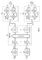
- FIG. 6 shows a schematic diagram of an exemplary design of a 2 ⁇ 2 MIMO LNA 640 based on a split cascode architecture.
- MIMO LNA 640 is one exemplary design of MIMO LNA 540 in FIG. 5 .
- MIMO LNA 640 includes two gain circuits 650 a and 650 b for two LNA inputs, a drive circuit 660 , and two load circuits 670 a and 670 b for two LNA outputs.
- each gain circuit 650 includes a source degeneration inductor 652 and a gain transistor 654 .
- a gain transistor 654 a has its gate receiving a first input RF signal, RFin 1 , and its source coupled to one end of inductor 652 a .
- the other end of inductor 652 a is coupled to circuit ground.
- Gain circuit 650 b includes a source degeneration inductor 652 b and a gain transistor 654 b , which are coupled in similar manner as inductor 652 a and transistor 654 a in gain circuit 650 a .
- Gain transistors 654 a and 654 b may be implemented with NMOS transistors, as shown in FIG. 6 , or with transistors of other types.
- Gain circuits 650 may also be implemented in other manners.
- a gain circuit may include a gain transistor having its source coupled directly to circuit ground (instead of to a source degeneration inductor).
- a gain circuit may include two gain transistors coupled in parallel and having their gates receiving an input RF signal.
- a first gain transistor may have its source coupled to a source degeneration inductor, as shown in FIG. 6 .
- a second gain transistor may have its source coupled directly to circuit ground. Either the first or second gain transistor may be selected.
- drive circuit 660 includes four cascode transistors 664 a to 664 d , which receive four control signals Vctrl 1 to Vctrl 4 , respectively, at their gates.
- Cascode transistors 664 a and 664 c have their sources coupled to the drain of gain transistor 654 a and their drains coupled to load circuits 670 a and 670 b , respectively.
- Cascode transistors 664 b and 664 d have their sources coupled to the drain of gain transistor 654 b and their drains coupled to load circuits 670 a and 670 b , respectively.
- Cascode transistors 664 may be implemented with NMOS transistors, as shown in FIG. 6 , or transistors of other types.
- Drive circuit 660 may also be implemented in other manners, as described below.
- each load circuit 670 includes a transformer 672 comprising a primary coil 674 and a secondary coil 676 .
- a transformer 672 a includes (i) a primary coil 674 a coupled between the drains of cascode transistors 664 a and 664 b and a power supply, VDD, and (ii) a secondary coil 676 a providing a differential first output RF signal.
- Load circuit 670 b includes a transformer 672 b having (i) a primary coil 674 b coupled between the drains of cascode transistors 664 c and 664 d and the VDD supply and (ii) a secondary coil 676 b providing a differential second output RF signal.
- Load circuits 670 may also be implemented in other manners.
- a load circuit may include an inductor and possibly a capacitor coupled between the VDD supply and the drains of one or more cascode transistors.
- the cascode transistors may provide the output RF signals at their drains.
- a load circuit may include a P-channel metal oxide semiconductor (PMOS) transistor having its source coupled to the VDD supply and its drain coupled to the drains of one or more cascode transistors.
- the PMOS transistor may provide an active load for the one or more cascode transistors.
- PMOS P-channel metal oxide semiconductor
- gain circuits 650 a and 650 b may each be enabled (i.e., turned on) or disabled (i.e., turned off). Each gain circuit 650 may be (i) disabled by applying a low voltage to the gate of gain transistor 654 within that gain circuit 650 or (ii) enabled by applying a suitable bias voltage to the gate of gain transistor 654 .
- an input RF signal may be applied directly to the gate of gain transistor 654 , as shown in FIG. 6 , and may be pulled to a low voltage to disable gain circuit 650 .
- the input RF signal may be applied to the gate of gain transistor 654 via an AC coupling/DC blocking capacitor (not shown in FIG. 6 ).
- a bias voltage may then be applied to the gate of gain transistor 654 via a resistor and may be set to a low voltage to disable gain circuit 650 .
- cascode transistors 664 a to 664 d within drive circuit 660 may each be enabled (i.e., turned on) or disabled (i.e., turned off). Each cascode transistor 664 may be (i) disabled by applying a low voltage to the gate of cascode transistor 664 or (ii) enabled by applying a suitable bias voltage to the gate of cascode transistor 664 . The Vctrl signal applied to the gate of each cascode transistor 664 may thus disable the cascode transistor or provide the proper bias voltage to enable the cascode transistor.
- MIMO LNA 640 may support a single-output mode, an intra-band CA mode, and an inter-band CA mode.
- a single input RF signal is applied to a single gain circuit 650 .
- a single output RF signal for one set of carriers is provided by a single load circuit 670 .
- the single-output mode may be used to receive transmission sent on a single carrier without carrier aggregation.
- the single-output mode may also be used to receive transmissions sent on multiple carriers (e.g., contiguous carriers) with carrier aggregation. In this case, the transmissions on all carriers may be downconverted with a single LO signal at a single frequency.
- a single input RF signal is applied to a single gain circuit 650 .
- Two output RF signals for two sets of carriers are provided by two load circuits 670 .
- two input RF signals for two bands are applied to two gain circuits 650 .
- Two output RF signals for two sets of carriers are provided by two load circuits 670 .
- FIG. 7A shows operation of MIMO LNA 640 in FIG. 6 in the single-output mode.
- MIMO LNA 640 operates in a 1 ⁇ 1 configuration with one LNA input and one LNA output.
- Either gain circuit 650 a or 650 b may be enabled to amplify a single input RF signal for a band of interest.
- Either load circuit 670 a or 670 b may be selected to provide a single output RF signal for a set of carriers of interest.
- One cascode transistor 664 within drive circuit 660 may be turned on to buffer an amplified RF signal from the selected gain circuit 650 and drive the selected load circuit 670 . In the example shown in FIG.
- gain circuit 650 a is selected to amplify the RFin 1 signal, and cascode transistor 664 a is turned on to buffer the amplified RF signal from gain circuit 650 a and drive selected load circuit 670 a .
- Gain circuit 650 b as well as cascode transistors 664 b to 664 d are turned off.
- Enabled gain circuit 650 a operates in a saturation region with the input RF signal applied to its gate and a bias current provided by cascode transistor 664 a .
- Disabled gain transistor 650 b operates in a linear region with the input RF signal applied to its gate but no bias current provided by any cascode transistor.
- FIG. 7B shows operation of MIMO LNA 640 in the intra-band CA mode.
- MIMO LNA 640 operates in a 1 ⁇ 2 configuration with one LNA input and two LNA outputs.
- Either gain circuit 650 a or 650 b may be enabled to amplify a single input RF signal for a band of interest.
- Both load circuits 670 a and 670 b may be selected to provide two output RF signals for two sets of carriers of interest.
- Two cascode transistors 664 within drive circuit 660 may be turned on to buffer the amplified RF signal from the selected gain circuit 650 and drive the two load circuits 670 . In the example shown in FIG.
- gain circuit 650 a is selected to amplify the RFin 1 signal, and cascode transistors 664 a and 664 c are turned on to buffer the amplified RF signal from gain circuit 650 a and drive load circuits 670 a and 670 b .
- Gain circuit 650 b as well as cascode transistors 664 b and 664 d are turned off.
- FIG. 7C shows operation of MIMO LNA 640 in the inter-band CA mode.
- MIMO LNA 640 operates in a 2 ⁇ 2 configuration with two LNA inputs and two LNA outputs.
- Both gain circuits 650 a or 650 b may be enabled to amplify two input RF signals for one or two bands of interest.
- Both load circuits 670 a and 670 b may be selected to provide two output RF signals for two sets of carriers of interest.
- Two cascode transistors 664 within drive circuit 660 may be turned on to buffer the two amplified RF signals from the two gain circuits 650 and drive the two load circuits 670 . In the example shown in FIG.
- cascode transistors 664 a and 664 d are turned on to buffer the amplified RF signals from gain circuits 650 a and 650 b , respectively, and drive load circuits 670 a and 670 b , respectively.
- Cascode transistors 664 b and 664 c are turned off.
- an input RF signal may be amplified by a gain transistor and may be split at the cascode level by providing the amplified RF signal from the gain transistor to multiple cascode transistors.
- the split cascode architecture may have approximately 6 decibel (dB) lower gain in a CA mode for a given amount of bias current. The lower gain may be accounted for in subsequent circuits.
- FIG. 8A shows a schematic diagram of an exemplary design of a 4 ⁇ 2 MIMO LNA 642 based on the split cascode architecture.
- MIMO LNA 642 is another exemplary design of MIMO LNA 540 in FIG. 5 .
- MIMO LNA 642 includes four gain circuits 650 a to 650 d for four LNA inputs, drive circuit 660 , and two load circuits 670 a and 670 b for two LNA outputs.
- Gain circuits 650 a and 650 b , drive circuit 660 , and load circuits 670 a and 670 b are coupled as described above for FIG. 6 .
- a gain transistor 654 c has its gate receiving a third input RF signal, RFin 3 , its source coupled to one end of an inductor 652 c , and its drain coupled to the source of cascode transistor 664 c .
- the other end of inductor 652 c is coupled to circuit ground.
- Gain circuit 650 d includes a source degeneration inductor 652 d and a gain transistor 654 d , which are coupled in similar manner as inductor 652 c and transistor 654 c in gain circuit 650 c .
- the drain of gain transistor 654 d is coupled to the source of cascode transistor 664 d.
- MIMO LNA 642 may support the single-output mode, the intra-band CA mode, and the inter-band CA mode.
- a single input RF signal may be received via one of the four LNA inputs and applied to a single gain circuit 650 .
- a single output RF signal for one set of carriers may be provided by a single load circuit 670 to one of the two LNA outputs.
- MIMO LNA 642 can support the single-output mode with an input RF signal applied to any one of the four gain circuits 650 .
- a single input RF signal may be received via one of the four LNA inputs and applied to a single gain circuit 650 .
- Two output RF signals for two sets of carriers may be provided by two load circuits 670 to the two LNA outputs.
- MIMO LNA 642 can allow an input RF signal to be applied to any gain circuit 650 and routed to any load circuit 670 .
- MIMO LNA 642 can support four combinations of input RF signals in the inter-band CA mode.
- the following combinations of input RF signals may be support: (RFin 1 , RFin 2 ), (RFin 1 , RFin 4 ), (RFin 2 , RFin 3 ), and (RFin 3 , RFin 4 ).
- the combination (RFin 1 , RFin 3 ) is not supported since the RFin 1 and RFin 3 signals are provided to gain transistors 654 a and 654 c having their drains coupled together.
- the combination (RFin 2 , RFin 4 ) is not supported since the RFin 2 and RFin 4 signals are provided to gain transistors 654 b and 654 d having their drains coupled together.
- FIG. 8B shows a schematic diagram of an exemplary design of a 4 ⁇ 2 MIMO LNA 644 based on the split cascode architecture.
- MIMO LNA 644 is yet another exemplary design of MIMO LNA 540 in FIG. 5 .
- MIMO LNA 644 includes four gain circuits 651 a to 651 d for four LNA inputs, drive circuit 660 , and two load circuits 670 a and 670 b for two LNA outputs.
- Each gain circuit 651 includes a gain transistor 654 , which is coupled to a source degeneration inductor 652 .
- Gain transistors 654 a and 654 b share the same source degeneration inductor 652 a .
- MIMO LNA 644 in FIG. 8B includes half of the source degeneration inductors as MIMO LNA 642 in FIG. 8A , which may provide some advantages such as smaller circuit area, lower cost, etc.
- MIMO LNA 644 may support the single-output mode and the intra-band CA mode as described above for MIMO LNA 642 in FIG. 8A .
- MIMO LNA 644 may also support the inter-band CA mode.
- only one of gain transistors 654 a and 654 b may be selected since they share the same source degeneration inductor 652 a .
- only one of gain transistors 654 c and 654 d may be selected since they share the same source degeneration inductor 652 c .
- only one of gain transistors 654 a and 654 c may be selected since their drains are coupled together, and only one of gain transistors 654 b and 654 d may be selected since their drains are also coupled together.
- LNA 644 may support two combinations of input RF signals, (RFin 1 , RFin 4 ) and (RFin 2 , RFin 3 ), in the inter-band CA mode.
- FIG. 8C shows a schematic diagram of an exemplary design of a 4 ⁇ 2 MIMO LNA 646 based on the split cascode architecture.
- MIMO LNA 646 is yet another exemplary design of MIMO LNA 540 in FIG. 5 .
- MIMO LNA 646 includes four gain circuits 650 a to 650 d for four LNA inputs, a drive circuit 662 , and two load circuits 670 a and 670 b for two LNA outputs.
- Drive circuit 662 includes cascode transistors 664 a to 664 d having their sources coupled to gain circuits 650 a to 650 d , respectively, and their drains coupled to load circuit 670 a .
- Drive circuit 662 further includes cascode transistors 666 a to 666 d having their sources coupled to gain circuits 650 a to 650 d , respectively, and their drains coupled to load circuit 670 b.
- MIMO LNA 646 may support the single-output mode and the intra-band CA mode as described above for MIMO LNA 642 in FIG. 8A .
- MIMO LNA 646 may also support the inter-band CA mode. In this mode, two input RF signals may be applied to any two gain circuits 650 since each gain circuit 650 is coupled to both load circuits 670 a and 670 b via two cascode transistors 664 and 666 .
- LNA 646 may support all six possible combinations of input RF signals, (RFin 1 , RFin 2 ), (RFin 1 , RFin 3 ), (RFin 1 , RFin 4 ), (RFin 2 , RFin 3 ), (RFin 2 , RFin 4 ), and (RFin 3 , RFin 4 ), in the inter-band CA mode.
- FIG. 8D shows a schematic diagram of an exemplary design of a 4 ⁇ 2 MIMO LNA 648 based on the split cascode architecture.
- MIMO LNA 648 is yet another exemplary design of MIMO LNA 540 in FIG. 5 .
- MIMO LNA 648 includes four gain circuits 651 a to 651 d for four LNA inputs, two source degeneration inductors 652 a and 652 c , drive circuit 662 , and two load circuits 670 a and 670 b for two LNA outputs.
- Gain circuits 651 a to 651 d include gain transistors 654 a to 654 d , which are coupled as described above for FIG. 8B .
- Drive circuit 662 includes cascode transistors 664 a to 664 d and cascode transistors 666 a to 666 d , which are coupled as described above for FIG. 8C .
- MIMO LNA 648 may support the single-output mode and the intra-band CA mode as described above for MIMO LNA 642 in FIG. 8A .
- MIMO LNA 648 may also support the inter-band CA mode. In this mode, two input RF signals may be applied to any two gain circuits 651 not sharing the same source degeneration inductor 652 .
- LNA 648 may support four combinations of input RF signals, (RFin 1 , RFin 3 ), (RFin 1 , RFin 4 ), (RFin 2 , RFin 3 ) and (RFin 2 , RFin 4 ), in the inter-band CA mode.
- FIGS. 8A to 8D show four exemplary designs of a 4 ⁇ 2 MIMO LNA based on the split cascode architecture.
- a MIMO LNA may include any number of inputs and any number of outputs.
- FIG. 9A shows a schematic diagram of an exemplary design of an N ⁇ M MIMO LNA 940 , where N and M may each be any integer value greater than one.
- MIMO LNA 940 is another exemplary design of MIMO LNA 540 in FIG. 5 .
- MIMO LNA 940 includes N gain circuits 950 a to 950 n for N LNA inputs, a drive circuit 960 , and M load circuits 970 a to 970 m for M LNA outputs.
- each gain circuit 950 may be implemented with a gain transistor having it source coupled to an inductor, e.g., as shown by gain circuit 650 a in FIG. 6 .
- each gain circuit 950 may be implemented with a gain transistor having its source coupled to circuit ground.
- multiple gain circuits 950 may be implemented with gain transistors having their sources coupled to a shared inductor, e.g., as shown in FIG. 8B .
- Drive circuit 960 may include cascode transistors coupled between gain circuits 950 a to 950 n and load circuits 970 a to 970 m .
- the number of cascode transistors may be dependent on the desired interconnection between the N gain circuits 950 and the M load circuits 970 .
- each gain circuit 950 may be coupled to each load circuit 970 via a cascode transistor.
- M cascode transistors may thus be coupled between each gain circuit 950 and the M load circuits 970 a to 970 m , e.g., as shown in FIG. 8C .
- a total of N*M cascode transistors may be used to implement full interconnection.
- each gain circuit 950 may be coupled to one load circuit 970 via a cascode transistor, e.g., as shown in FIG. 8A .
- each gain circuit 950 may be coupled to at least two load circuits 970 via at least two cascode transistors, e.g., as shown in FIG. 8C .
- MIMO LNA 940 may support the single-output mode, the intra-band CA mode, and the inter-band CA mode.
- a single input RF signal may be received via one of the N LNA inputs and applied to a single gain circuit 950 .
- a single output RF signal for one set of carriers may be provided by a single load circuit 970 to one of the M LNA outputs.
- a single input RF signal may be received via one of the N LNA inputs and applied to a single gain circuit 950 .
- Multiple output RF signals for multiple sets of carriers may be provided by multiple load circuits 970 to multiple LNA outputs.
- the inter-band CA mode multiple input RF signals for multiple bands may be received via multiple LNA inputs and applied to multiple gain circuits 950 .
- Multiple output RF signals for multiple sets of carriers may be provided by multiple load circuits 970 to multiple LNA outputs.
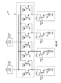
- FIG. 9B shows a schematic diagram of an exemplary design of an N ⁇ M MIMO LNA 942 , where N and M may each be any integer value greater than one.
- MIMO LNA 942 is another exemplary design of MIMO LNA 540 in FIG. 5 .
- MIMO LNA 942 includes N low-gain circuits 952 a to 952 n and N high-gain circuits 954 a to 954 n for N LNA inputs, a drive circuit 962 , and M load circuits 970 a to 970 m for M LNA outputs.
- each high-gain circuit 954 may be implemented with a gain transistor having it source coupled to an inductor, e.g., as shown by gain circuit 650 a in FIG. 6 .
- multiple high-gain circuits 954 may be implemented with gain transistors having their sources coupled to a shared inductor, e.g., as shown in FIG. 8B .
- Each low-gain circuit 952 may be implemented as described below.
- Drive circuit 962 may include cascode transistors coupled between low-gain circuits 952 a to 952 n and high-gain circuits 954 a to 954 n and load circuits 970 a to 970 m . The number of cascode transistors may be dependent on the desired interconnection between gain circuits 952 and 954 and load circuits 970 .
- MIMO LNA 942 may support the single-output mode, the intra-band CA mode, and the inter-band CA mode, e.g., as described above for MIMO LNA 940 in FIG. 9A .
- MIMO LNA 942 may also support a high-gain mode and a low-gain mode.
- In the high-gain mode one or more high-gain circuits 954 may be selected to amplify one or more input RF signals and provide one or more amplified RF signals.
- the low-gain mode one or more low-gain circuits 952 may be selected to amplify one or more input RF signals and provide one or more amplified RF signals.
- Drive circuit 962 may receive one or more amplified RF signals from one or more high-gain circuits 954 and/or one or more low-gain circuits 952 and may provide one or more drive signals for one or more load circuits 970 .
- FIG. 10 shows a schematic diagram of an exemplary design of a low-gain circuit 952 x .
- Low-gain circuit 952 x may be used for any one of low-gain circuits 952 a to 952 n in FIG. 9B .
- an NMOS transistor 1058 has its source coupled to the input of low-gain circuit 952 x , its gate receiving a control signal, Enb, and its drain coupled to the input of an attenuation circuit 1060 .
- Attenuation circuit 1060 includes (i) a resistor 1062 coupled between the input and output of attenuation circuit 1060 and (ii) a variable resistor 1064 coupled between the output of attenuation circuit 1060 and circuit ground.
- An AC coupling capacitor 1068 is coupled between the output of attenuation circuit 1060 and the gate of an NMOS transistor 1054 .
- NMOS transistor 1054 has its source coupled to circuit ground and its drain providing an amplified RF signal when low-gain circuit 952 x is enabled.
- NMOS transistor 1058 operates as a switch that can pass an input RF signal to NMOS transistor 1054 when NMOS transistor 1058 is enabled by the Enb signal.
- Attenuation circuit 1060 can attenuate the input RF signal by a variable amount based on the setting of variable resistor 1064 .
- NMOS transistor 1054 is a gain transistor that can amplify the RF signal from attenuation circuit 1060 .
- a high-gain circuit may be implemented with a gain transistor having its source coupled to a degeneration inductor, e.g., as shown in FIG. 6 .
- a high-gain circuit may also be implemented with (i) a gain transistor having its source coupled to circuit ground and (ii) a feedback circuit coupled between the drain of a cascode transistor and the gate of the gain transistor.
- the feedback circuit may include a resistor coupled in series with a capacitor.
- a switch may also be coupled in series with the resistor and the capacitor and may be used to connect or disconnect the feedback circuit.
- the feedback circuit may help with the input matching and linearity.
- the MIMO LNAs described herein may include various desirable features including:
- Single-ended LNA inputs may reduce the number of input ports as well as the number of circuit components for input matching circuits on a printed circuit board (PCB) containing a MIMO LNA.
- a MIMO LNA may support twice as many receive paths for a given number of input ports with single-ended LNA inputs.
- Differential LNA outputs may reduce LO leakage and second-order effects by balancing the signals in downconverter circuits. In general, all advantages of differential circuits versus single-ended circuits may be obtained with the differential LNA outputs.
- Transformer/inductive loads may allow a MIMO LNA to operate with a low power supply voltage since these circuit components do not waste any voltage headroom.
- Other types of loads e.g., active/transistor loads
- Inductive degeneration may be used to improve linearity in high-gain LNA as well as to aid input matching to a target impedance (e.g., 50 Ohms). Without degeneration inductors, receiver performance (e.g., for input matching and linearity) may not meet specification requirements.
- an apparatus may include a plurality of gain circuits, a drive circuit, and a plurality of load circuits.
- the plurality of gain circuits (e.g., gain circuits 650 in FIG. 6 or 8 A) may receive at least one input RF signal and provide at least one amplified RF signal.
- Each gain circuit may receive and amplify one input RF signal and providing one amplified RF signal when the gain circuit is enabled.
- the at least one input RF signal may comprise transmissions sent on multiple carriers at different frequencies to the wireless device.
- the drive circuit e.g., drive circuit 660 in FIG. 6 or FIG.
- the drive circuit may receive the at least one amplified RF signal and provide at least one drive RF signal.
- the plurality of load circuits e.g., load circuits 670 in FIG. 6 or 8 A
- each gain circuit may comprise a gain transistor (e.g., NMOS transistor 654 in FIG. 6 or 8 A) that receives an input RF signal and provides an amplified RF signal when the gain circuit is enabled.
- a gain circuit e.g., gain circuit 650 a in FIG. 6A or 8 A
- a gain transistor e.g., gain transistor 1054 in FIG. 10
- the plurality of gain circuits may include at least two sets of gain circuits, with each set including two or more gain circuits.
- Each set of gain circuits may include a set of gain transistors (e.g., two gain transistors) sharing an inductor coupled to circuit ground (e.g., as shown in FIG. 8B ).
- the plurality of gain circuits may also include a plurality of high-gain circuits and a plurality of low-gain circuits, e.g., as shown in FIG. 9B .
- Either a low-gain circuit or a high-gain circuit may be selected for an input RF signal, e.g., depending on the received power level of the input RF signal.
- the high-gain circuit may include source inductive degeneration to improve linearity at high gain.
- the low-gain circuit may include no source inductive degeneration.
- the drive circuit may comprise a plurality of cascode transistors (e.g., cascode transistors 664 in FIG. 6 or 8 A).
- Each cascode transistor may be coupled between one of the plurality of gain circuits and one of the plurality of load circuits.
- each gain circuit may be coupled to each of the plurality of load circuits via a respective cascode transistor.
- each gain circuit may be coupled to two load circuits (which may be a subset of the plurality of load circuits) via two cascode transistors.
- a given cascode transistor may also be shared by multiple gain circuits. For example, cascode transistor 664 a in FIG. 8A is shared by gain circuits 650 a and 650 c.
- each load circuit may comprise a transformer (e.g., transformer 672 in FIG. 6 ) having a primary coil and a secondary coil.
- the primary coil may be coupled between the drive circuit and a power supply.
- the secondary coil may provide a differential output RF signal when a drive RF signal is applied to the primary coil.
- each load circuit may comprise an inductor coupled between the drive circuit and a power supply.
- a load circuit may also comprise a transistor and/or other circuits.
- the apparatus may further include a plurality of input matching circuits (e.g., input matching circuits 532 in FIG. 5 ) coupled to the plurality of gain circuits.
- Each input matching circuit may perform power and/or impedance matching for a different band or a different set of bands.
- the apparatus may further include a plurality of downconverter circuits (e.g., downconverter circuits 590 in FIG. 5 ) coupled to the plurality of load circuits.
- the downconverter circuits may perform downconversion of the at least one output RF signal based on at least one LO signal.
- Each LO signal may be at a different frequency, which may be determined based on one or more carriers being downconverted by the associated downconverter circuit.
- each input RF signal may comprise a single-ended signal, and each output RF signal may comprise a differential signal, e.g., as shown in FIG. 6 .
- each input RF signal may comprise a single-ended signal, and each output RF signal may comprise a single-ended signal.
- each input RF signal may comprise a differential signal, and each output RF signal may comprise a differential signal.
- the apparatus may operate in one of a plurality of modes.
- one gain circuit may be enabled to receive and amplify one input RF signal and provide one amplified RF signal.
- the drive circuit may receive the amplified RF signal and provide one drive RF signal.
- One load circuit may receive the drive RF signal and provide one output RF signal.
- one gain circuit in an intra-band CA mode, may be enabled to receive and amplify one input RF signal and provide one amplified RF signal.
- the drive circuit may receive the amplified RF signal and providing at least two drive RF signals.
- At least two load circuits may receive the at least two drive RF signals and provide at least two output RF signals.
- the one input RF signal may comprise transmissions sent on multiple carriers in a single band.
- At least two gain circuits may be enabled to receive and amplify at least two input RF signals and provide at least two amplified RF signals.
- the drive circuit may receive the at least two amplified RF signals and provide at least two drive RF signals.
- At least two load circuits may receive the at least two drive RF signals and provide at least two output RF signals.
- the at least two input RF signals may comprise transmissions sent on multiple carriers in at least two bands.
- FIG. 11 shows an exemplary design of a process 1100 for performing signal amplification in a wireless system.
- Process 1100 may be performed by a wireless device or by some other entity.
- At least one input RF signal comprising transmissions sent on multiple carriers at different frequencies to a wireless device may be amplified (e.g., with at least one of a plurality of gain circuits) to obtain at least one amplified RF signal (block 1112 ).
- At least one drive RF signal may be generated based on the at least one amplified RF signal, e.g., with a drive circuit coupled to the plurality of gain circuits (block 1114 ).
- At least one output RF signal may be provided based on the at least one drive RF signal, e.g., with at least one of a plurality of load circuits coupled to the drive circuit (block 1116 ).
- each input RF signal may comprise a single-ended signal
- each output RF signal may comprise a differential signal.
- one input RF signal may be amplified (e.g., with one gain circuit) to obtain one amplified RF signal.
- One drive RF signal may be generated (e.g., by the drive circuit) based on the amplified RF signal.
- One output RF signal may be provided (e.g., by one load circuit) based on the drive RF signal.
- one input RF signal may be amplified (e.g., with one gain circuit) to obtain one amplified RF signal.
- At least two drive RF signals may be generated (e.g., by the drive circuit) based on the amplified RF signal.
- At least two output RF signals may be provided (e.g., by at least two load circuits) based on the at least two drive RF signals.
- At least two input RF signals may be amplified (e.g., with at least two gain circuits) to obtain at least two amplified RF signals.
- At least two drive RF signals may be generated (e.g., by the drive circuit) based on the at least two amplified RF signals.
- At least two output RF signals may be provided (e.g., by at least two load circuits) based on the at least two drive RF signals.
- the MIMO LNAs described herein may be implemented on an IC, an analog IC, an RFIC, a mixed-signal IC, an ASIC, a PCB, an electronic device, etc.
- the MIMO LNAs may also be fabricated with various IC process technologies such as complementary metal oxide semiconductor (CMOS), NMOS, PMOS, bipolar junction transistor (BJT), bipolar-CMOS (BiCMOS), silicon germanium (SiGe), gallium arsenide (GaAs), heterojunction bipolar transistors (HBTs), high electron mobility transistors (HEMTs), silicon-on-insulator (SOI), etc.
- CMOS complementary metal oxide semiconductor
- NMOS NMOS
- PMOS bipolar junction transistor
- BiCMOS bipolar-CMOS
- SiGe silicon germanium
- GaAs gallium arsenide
- HBTs heterojunction bipolar transistors
- HEMTs high electron mobility transistors
- SOI silicon-on-insulator
- An apparatus implementing the MIMO LNAs described herein may be a stand-alone device or may be part of a larger device.
- a device may be (i) a stand-alone IC, (ii) a set of one or more ICs that may include memory ICs for storing data and/or instructions, (iii) an RFIC such as an RF receiver (RFR) or an RF transmitter/receiver (RTR), (iv) an ASIC such as a mobile station modem (MSM), (v) a module that may be embedded within other devices, (vi) a receiver, cellular phone, wireless device, handset, or mobile unit, (vii) etc.
- RFR RF receiver
- RTR RF transmitter/receiver
- MSM mobile station modem
- the functions described may be implemented in hardware, software, firmware, or any combination thereof. If implemented in software, the functions may be stored on or transmitted over as one or more instructions or code on a computer-readable medium.
- Computer-readable media includes both computer storage media and communication media including any medium that facilitates transfer of a computer program from one place to another.
- a storage media may be any available media that can be accessed by a computer.
- such computer-readable media can comprise RAM, ROM, EEPROM, CD-ROM or other optical disk storage, magnetic disk storage or other magnetic storage devices, or any other medium that can be used to carry or store desired program code in the form of instructions or data structures and that can be accessed by a computer.
- any connection is properly termed a computer-readable medium.
- the software is transmitted from a website, server, or other remote source using a coaxial cable, fiber optic cable, twisted pair, digital subscriber line (DSL), or wireless technologies such as infrared, radio, and microwave
- the coaxial cable, fiber optic cable, twisted pair, DSL, or wireless technologies such as infrared, radio, and microwave are included in the definition of medium.
- Disk and disc includes compact disc (CD), laser disc, optical disc, digital versatile disc (DVD), floppy disk and blu-ray disc where disks usually reproduce data magnetically, while discs reproduce data optically with lasers. Combinations of the above should also be included within the scope of computer-readable media.
Abstract
Description
-
- 1. Single-ended LNA inputs and differential LNA outputs,
- 2. Transformer/inductive loads for MIMO LNA, and
- 3. Inductive degeneration at LNA inputs for high gain and bypassed for low gain.
Claims (20)
Priority Applications (4)
| Application Number | Priority Date | Filing Date | Title |
|---|---|---|---|
| US13/593,764 US9154357B2 (en) | 2012-05-25 | 2012-08-24 | Multiple-input multiple-output (MIMO) low noise amplifiers for carrier aggregation |
| CN201380026660.0A CN104335483B (en) | 2012-05-25 | 2013-05-24 | Multiple-input and multiple-output for carrier aggregation(MIMO)Low-noise amplifier |
| PCT/US2013/042761 WO2013177572A1 (en) | 2012-05-25 | 2013-05-24 | Multiple-input multiple-output (mimo) low noise amplifiers for carrier aggregation |
| EP13728607.6A EP2856641B1 (en) | 2012-05-25 | 2013-05-24 | Multiple-input multiple-output (mimo) low noise amplifiers for carrier aggregation |
Applications Claiming Priority (2)
| Application Number | Priority Date | Filing Date | Title |
|---|---|---|---|
| US201261652064P | 2012-05-25 | 2012-05-25 | |
| US13/593,764 US9154357B2 (en) | 2012-05-25 | 2012-08-24 | Multiple-input multiple-output (MIMO) low noise amplifiers for carrier aggregation |
Publications (2)
| Publication Number | Publication Date |
|---|---|
| US20130316670A1 US20130316670A1 (en) | 2013-11-28 |
| US9154357B2 true US9154357B2 (en) | 2015-10-06 |
Family
ID=49621593
Family Applications (4)
| Application Number | Title | Priority Date | Filing Date |
|---|---|---|---|
| US13/590,423 Active US9154356B2 (en) | 2012-05-25 | 2012-08-21 | Low noise amplifiers for carrier aggregation |
| US13/593,764 Active US9154357B2 (en) | 2012-05-25 | 2012-08-24 | Multiple-input multiple-output (MIMO) low noise amplifiers for carrier aggregation |
| US13/599,919 Active 2032-09-30 US9166852B2 (en) | 2012-05-25 | 2012-08-30 | Low noise amplifiers with transformer-based signal splitting for carrier aggregation |
| US13/608,777 Active US9160598B2 (en) | 2012-05-25 | 2012-09-10 | Low noise amplifiers with cascode divert switch for carrier aggregation |
Family Applications Before (1)
| Application Number | Title | Priority Date | Filing Date |
|---|---|---|---|
| US13/590,423 Active US9154356B2 (en) | 2012-05-25 | 2012-08-21 | Low noise amplifiers for carrier aggregation |
Family Applications After (2)
| Application Number | Title | Priority Date | Filing Date |
|---|---|---|---|
| US13/599,919 Active 2032-09-30 US9166852B2 (en) | 2012-05-25 | 2012-08-30 | Low noise amplifiers with transformer-based signal splitting for carrier aggregation |
| US13/608,777 Active US9160598B2 (en) | 2012-05-25 | 2012-09-10 | Low noise amplifiers with cascode divert switch for carrier aggregation |
Country Status (9)
| Country | Link |
|---|---|
| US (4) | US9154356B2 (en) |
| EP (4) | EP2856641B1 (en) |
| JP (3) | JP6290190B2 (en) |
| KR (3) | KR102160715B1 (en) |
| CN (6) | CN104365017B (en) |
| BR (1) | BR112014029217A2 (en) |
| ES (1) | ES2755030T3 (en) |
| HU (1) | HUE045213T2 (en) |
| WO (4) | WO2013177572A1 (en) |
Cited By (10)
| Publication number | Priority date | Publication date | Assignee | Title |
|---|---|---|---|---|
| US20160020738A1 (en) * | 2014-07-16 | 2016-01-21 | Samsung Electronics Co., Ltd. | Diversity amp module and apparatus comprising the same |
| US9431963B2 (en) | 2014-09-19 | 2016-08-30 | Qualcomm Incorporated | Dual stage low noise amplifier for multiband receiver |
| US9503149B1 (en) * | 2015-07-28 | 2016-11-22 | Beijing Lenovo Software Ltd. | Electronic device and control method thereof |
| US9603187B2 (en) | 2012-11-14 | 2017-03-21 | Qualcomm Incorporated | Omni-band amplifiers |
| US9800273B1 (en) | 2017-03-01 | 2017-10-24 | Qualcomm Incorporated | Wideband high linearity LNA with intra-band carrier aggregation support |
| US10177722B2 (en) | 2016-01-12 | 2019-01-08 | Qualcomm Incorporated | Carrier aggregation low-noise amplifier with tunable integrated power splitter |
| EP3550721A1 (en) * | 2018-04-04 | 2019-10-09 | Samsung Electronics Co., Ltd. | Radio frequency (rf) integrated circuit performing signal amplification operation to support carrier aggregation and receiver including the same |
| US10686413B2 (en) * | 2018-04-26 | 2020-06-16 | Samsung Electro-Mechanics Co., Ltd. | Low noise amplifier circuit with multiple-input multiple-output (MIMO) structure |
| US11146161B2 (en) | 2019-08-01 | 2021-10-12 | Samsung Electronics Co., Ltd. | Electronic system including voltage regulators |
| US11283409B2 (en) | 2019-08-30 | 2022-03-22 | Qualcomm Incorporated | Signal combiner |
Families Citing this family (112)
| Publication number | Priority date | Publication date | Assignee | Title |
|---|---|---|---|---|
| US9026070B2 (en) | 2003-12-18 | 2015-05-05 | Qualcomm Incorporated | Low-power wireless diversity receiver with multiple receive paths |
| US9450665B2 (en) | 2005-10-19 | 2016-09-20 | Qualcomm Incorporated | Diversity receiver for wireless communication |
| US9178669B2 (en) | 2011-05-17 | 2015-11-03 | Qualcomm Incorporated | Non-adjacent carrier aggregation architecture |
| US9252827B2 (en) | 2011-06-27 | 2016-02-02 | Qualcomm Incorporated | Signal splitting carrier aggregation receiver architecture |
| US9154179B2 (en) | 2011-06-29 | 2015-10-06 | Qualcomm Incorporated | Receiver with bypass mode for improved sensitivity |
| US8774334B2 (en) | 2011-11-09 | 2014-07-08 | Qualcomm Incorporated | Dynamic receiver switching |
| JP6041498B2 (en) * | 2012-02-03 | 2016-12-07 | 株式会社Nttドコモ | Mobile communication method, radio base station, and mobile station |
| US9362958B2 (en) | 2012-03-02 | 2016-06-07 | Qualcomm Incorporated | Single chip signal splitting carrier aggregation receiver architecture |
| US9172402B2 (en) | 2012-03-02 | 2015-10-27 | Qualcomm Incorporated | Multiple-input and multiple-output carrier aggregation receiver reuse architecture |
| US9118439B2 (en) | 2012-04-06 | 2015-08-25 | Qualcomm Incorporated | Receiver for imbalanced carriers |
| US9154356B2 (en) | 2012-05-25 | 2015-10-06 | Qualcomm Incorporated | Low noise amplifiers for carrier aggregation |
| US9867194B2 (en) | 2012-06-12 | 2018-01-09 | Qualcomm Incorporated | Dynamic UE scheduling with shared antenna and carrier aggregation |
| US9300420B2 (en) | 2012-09-11 | 2016-03-29 | Qualcomm Incorporated | Carrier aggregation receiver architecture |
| US9543903B2 (en) | 2012-10-22 | 2017-01-10 | Qualcomm Incorporated | Amplifiers with noise splitting |
| US9897686B2 (en) * | 2013-02-12 | 2018-02-20 | Nxp Usa, Inc. | Active IQ and quadrature generator for high frequency applications |
| US8995591B2 (en) | 2013-03-14 | 2015-03-31 | Qualcomm, Incorporated | Reusing a single-chip carrier aggregation receiver to support non-cellular diversity |
| US9035697B2 (en) * | 2013-03-15 | 2015-05-19 | Qualcomm Incorporated | Split amplifiers with improved linearity |
| US20150004922A1 (en) * | 2013-06-27 | 2015-01-01 | Samsung Electronics Co., Ltd. | Modulation circuit and wireless communication apparatus |
| US8929945B1 (en) * | 2013-07-18 | 2015-01-06 | Mstar Semiconductor, Inc. | Transceivers with a transformer supporting multiband operation |
| BR112016003111B8 (en) * | 2013-08-16 | 2022-08-16 | Ericsson Telefon Ab L M | RECEIVER CIRCUIT, METHOD FOR CONTROLLING THE ADAPTATION OF A RECEIVER CIRCUIT, COMPUTER-READable STORAGE MEDIA, AND, COMMUNICATION DEVICE |
| US9263998B2 (en) * | 2013-12-16 | 2016-02-16 | Mstar Semiconductor, Inc. | Broadband single-ended input to differential output low-noise amplifier |
| US9178473B2 (en) | 2013-12-19 | 2015-11-03 | Qualcomm Incorporated | Distortion cancellation for low noise amplifier (LNA) non-linear second order products |
| US20150180694A1 (en) * | 2013-12-19 | 2015-06-25 | Nvidia Corporation | Radio frequency circuit for intra-band and inter-band carrier aggregation |
| US9270303B2 (en) * | 2013-12-30 | 2016-02-23 | Broadcom Corporation | Configurable receiver architecture for carrier aggregation with multiple-input multiple-output |
| US9425832B2 (en) * | 2014-01-16 | 2016-08-23 | Qualcomm Incorporated | Inter carrier-aggregation isolation in a receiver |
| US9319007B2 (en) * | 2014-01-30 | 2016-04-19 | National Taiwan University | Three-dimensional power amplifier architecture |
| US9271239B2 (en) * | 2014-02-14 | 2016-02-23 | Qualcomm Incorporated | Current-efficient low noise amplifier (LNA) |
| EP2913922A1 (en) * | 2014-02-28 | 2015-09-02 | Telefonaktiebolaget L M Ericsson (publ) | A low noise amplifier circuit |
| US9413406B2 (en) | 2014-03-14 | 2016-08-09 | Qualcomm Incorporated | Single input multiple-output power amplifier |
| US9374042B2 (en) | 2014-03-27 | 2016-06-21 | Infineon Technologies Ag | System and method for a low noise amplifier |
| US9425746B2 (en) * | 2014-03-28 | 2016-08-23 | Qualcomm Incorporated | Spurious signal mitigation for carrier aggregation amplifier |
| US9467104B2 (en) | 2014-03-28 | 2016-10-11 | Qualcomm Incorporated | Single-input multiple-output amplifiers with simultaneous multiple gain modes |
| GB2591952B (en) * | 2014-04-11 | 2021-12-29 | Skyworks Solutions Inc | Circuits and methods related to switchless carrier aggregation in radio-frequency receivers |
| US9723560B2 (en) * | 2014-05-22 | 2017-08-01 | Qualcomm Incorporated | Multi-stage amplifier with RC network |
| US9479131B2 (en) * | 2014-05-23 | 2016-10-25 | Qualcomm Incorporated | Carrier aggregation amplifier with dual gain control |
| US9525503B2 (en) | 2014-05-28 | 2016-12-20 | Qualcomm Incorporated | Reconfigurable multi-mode transceiver |
| US9642166B2 (en) * | 2014-05-29 | 2017-05-02 | Qualcomm Incorporated | Cross-connected cascode low noise amplifier for carrier aggregation |
| US9379673B2 (en) | 2014-05-30 | 2016-06-28 | Qualcomm Incorporated | Distortion cancellation for dual stage carrier-aggregation (CA) low noise amplifier (LNA) non-linear second order products |
| US9787258B2 (en) * | 2014-07-14 | 2017-10-10 | Skyworks Solutions, Inc. | Circuits and devices related to fast turn-on of radio-frequency amplifiers |
| EP2978130B1 (en) * | 2014-07-24 | 2019-09-11 | Renesas Electronics Europe GmbH | Circuit for controlling slew rate of a high-side switching element |
| US20160036392A1 (en) * | 2014-07-30 | 2016-02-04 | Qualcomm Incorporated | Dual-band amplifier |
| KR102196752B1 (en) * | 2014-08-12 | 2020-12-30 | 삼성전자주식회사 | Apparatus for transmitting and receiving carrier aggregation signal |
| US9479126B2 (en) * | 2014-08-19 | 2016-10-25 | Infineon Technologies Ag | System and method for a low noise amplifier |
| GB2547119B (en) * | 2014-08-29 | 2021-10-06 | Skyworks Solutions Inc | Domino circuit and related architectures and methods for carrier aggregation |
| US9385901B2 (en) | 2014-11-13 | 2016-07-05 | Qualcomm Incorporated | Receiver front end architecture for intra band carrier aggregation |
| US9641139B2 (en) * | 2014-11-17 | 2017-05-02 | Mediatek Inc. | Amplifier and related method |
| US20160173145A1 (en) * | 2014-12-16 | 2016-06-16 | Nvidia Corporation | Low noise amplifier providing variable gains and noise cancellation for carrier aggregation |
| US9831838B2 (en) | 2014-12-16 | 2017-11-28 | Nvidia Corporation | Low noise amplifier architecture for carrier aggregation receivers |
| US9407205B2 (en) * | 2014-12-23 | 2016-08-02 | Macom Technology Solutions Holdings, Inc. | Double down-conversion with multiple independent intermediate frequencies for E-band applications |
| US9712117B2 (en) | 2014-12-30 | 2017-07-18 | Skyworks Solutions, Inc. | Cascode switch for power amplifier |
| CN105790777B (en) * | 2015-01-13 | 2021-02-19 | 三星电子株式会社 | Receiver and wireless terminal for signal processing |
| KR102384866B1 (en) * | 2015-01-13 | 2022-04-08 | 삼성전자주식회사 | Receiver, Wireless Terminal, Operating Method of Wireless Terminal |
| US20160218852A1 (en) * | 2015-01-22 | 2016-07-28 | Qualcomm Incorporated | Half-duplex sawless receiver |
| US9589916B2 (en) * | 2015-02-10 | 2017-03-07 | Infineon Technologies Ag | Inductively coupled transformer with tunable impedance match network |
| US10187023B2 (en) * | 2015-02-15 | 2019-01-22 | Skyworks Solutions, Inc. | Power amplifier with cascode switching or splitting functionality |
| US10211861B2 (en) | 2015-03-17 | 2019-02-19 | Skyworks Solutions, Inc. | Multi-mode integrated front end module |
| WO2016155791A1 (en) * | 2015-03-31 | 2016-10-06 | Telefonaktiebolaget Lm Ericsson (Publ) | Receiving a plurality of radio frequency bands |
| US9515749B2 (en) * | 2015-05-07 | 2016-12-06 | Qualcomm Incorporated | Low noise amplifier module with output coupler |
| US9712195B2 (en) | 2015-05-13 | 2017-07-18 | Qualcomm Incorporated | Radio frequency low noise amplifier with on-chip matching and built-in tunable filter |
| CN104935287B (en) * | 2015-06-26 | 2018-01-30 | 英特尔公司 | Radio frequency receiver and its inductive single ended input difference output low-noise amplifier |
| US9774303B1 (en) * | 2015-08-25 | 2017-09-26 | Marvell International Ltd. | Low-noise amplifier for intra-band non contiguous carrier agregation |
| US9712113B2 (en) | 2015-12-01 | 2017-07-18 | Analog Devices Global | Local oscillator paths |
| US9755678B2 (en) | 2015-12-01 | 2017-09-05 | Analog Devices Global | Low noise transconductance amplifiers |
| US10608600B2 (en) * | 2015-12-23 | 2020-03-31 | Analog Devices, Inc | Adaptable receiver amplifier |
| WO2017120307A1 (en) * | 2016-01-06 | 2017-07-13 | Project Ft, Inc. | Memoryless common-mode insensitive and low pulling vco |
| US10033338B2 (en) * | 2016-06-17 | 2018-07-24 | Qualcomm Incorporated | Switched inductor/transformer for dual-band low-noise amplifier (LNA) |
| US10033337B2 (en) * | 2016-08-09 | 2018-07-24 | Qualcomm Incorporated | Multi-stage bandpass low-noise amplifier |
| DE112017004352T5 (en) * | 2016-08-31 | 2019-05-23 | Skyworks Solutions, Inc. | Multi-input amplifier with degenerating switch block and low-loss bypass function |
| JP6623133B2 (en) | 2016-09-05 | 2019-12-18 | 株式会社東芝 | High frequency semiconductor amplifier circuit |
| US9774302B1 (en) | 2016-09-27 | 2017-09-26 | Globalfoundries Inc. | Amplifier circuit with single-ended input and differential outputs |
| US10250195B2 (en) | 2016-11-18 | 2019-04-02 | Samsung Electronics Co., Ltd. | Receiver receiving wideband radio frequency signal, wireless communication device including the same, and method of operating the wireless communication device |
| US10516432B2 (en) | 2016-12-01 | 2019-12-24 | Mediatek Inc. | Communication system with switchable devices |
| US10411658B2 (en) | 2016-12-14 | 2019-09-10 | Kabushiki Kaisha Toshiba | Semiconductor device |
| US10122332B2 (en) | 2016-12-14 | 2018-11-06 | Qualcomm Incorporated | Low-noise amplifier with integrated wideband transformer-based power splitter |
| KR20180070328A (en) | 2016-12-16 | 2018-06-26 | 삼성전자주식회사 | Low noise amplifier for carrier aggregation and apparatus including the same |
| KR102534861B1 (en) * | 2016-12-23 | 2023-05-22 | 삼성전자주식회사 | Amplifier module and control method thereof |
| US10033340B1 (en) | 2017-01-06 | 2018-07-24 | Qualcomm Incorporated | Low-noise amplifier (LNA) with capacitive attenuator |
| US10038418B1 (en) | 2017-04-04 | 2018-07-31 | Psemi Corporation | Optimized multi gain LNA enabling low current and high linearity including highly linear active bypass |
| US11881828B2 (en) | 2017-04-04 | 2024-01-23 | Psemi Corporation | Tunable effective inductance for multi-gain LNA with inductive source degeneration |
| JP6761374B2 (en) | 2017-05-25 | 2020-09-23 | 株式会社東芝 | Semiconductor device |
| CN109412537B (en) * | 2017-08-15 | 2022-10-14 | 诺基亚通信公司 | Low noise amplifier protection |
| US10680560B2 (en) * | 2017-08-30 | 2020-06-09 | Mediatek, Inc. | Transformer or inductor sharing in a radio frequency amplifier and method therefor |
| CN109429303B (en) * | 2017-08-30 | 2021-01-15 | 中国移动通信有限公司研究院 | Network searching method, terminal and computer readable storage medium |
| CN107888153A (en) * | 2017-10-20 | 2018-04-06 | 江苏卓胜微电子股份有限公司 | A kind of low-noise amplifier and the radio frequency amplification method using low-noise amplifier |
| CN107809259B (en) * | 2017-11-09 | 2019-09-06 | 广东凯亨信息科技有限公司 | A kind of wireless signal enhancement device |
| US10965261B2 (en) * | 2017-12-05 | 2021-03-30 | Qualcomm Incorporated | Power amplifier circuit |
| WO2019190543A1 (en) * | 2018-03-30 | 2019-10-03 | Mohammed Alam | Low-noise amplifier supporting multicarrier operations |
| US10855317B2 (en) | 2018-04-05 | 2020-12-01 | Swiftlink Technologies Inc. | Broadband receiver for multi-band millimeter-wave wireless communication |
| JP6951293B2 (en) | 2018-05-29 | 2021-10-20 | 株式会社東芝 | Semiconductor device |
| US10707817B2 (en) * | 2018-05-30 | 2020-07-07 | Speedlink Technology Inc. | Wideband low noise amplifier (LNA) with a reconfigurable bandwidth for millimeter-wave 5G communication |
| US11251880B2 (en) * | 2018-07-19 | 2022-02-15 | Futurewei Technologies, Inc. | CA power measurement |
| JP2020017812A (en) * | 2018-07-24 | 2020-01-30 | 日本電気株式会社 | amplifier |
| CN110957980B (en) * | 2018-09-27 | 2023-06-20 | 天津大学青岛海洋技术研究院 | Millimeter wave active orthogonal signal generator based on SiGe process |
| US10574287B1 (en) * | 2018-09-28 | 2020-02-25 | Qualcomm Incorporated | Wireless transceiver with reconfigurable transformers |
| TWI672903B (en) | 2018-10-03 | 2019-09-21 | 立積電子股份有限公司 | Amplifier circuit |
| KR102463983B1 (en) * | 2018-12-26 | 2022-11-07 | 삼성전자 주식회사 | An amplifier for cutting a leakage current and an electronic device including the amplifier |
| JP7185548B2 (en) * | 2019-02-07 | 2022-12-07 | 株式会社東芝 | high frequency amplifier circuit |
| US10771025B1 (en) | 2019-02-19 | 2020-09-08 | Psemi Corporation | RFFE LNA topology supporting both noncontiguous intraband carrier aggregation and interband carrier aggregation |
| EP3956981A4 (en) * | 2019-04-19 | 2023-01-18 | Swiftlink Technologies Co., Ltd. | Broadband receiver for multi-band millimeter-wave wireless communication |
| KR20210031169A (en) | 2019-09-11 | 2021-03-19 | 삼성전자주식회사 | Receiver circuit and receiving system |
| US11139791B2 (en) * | 2019-09-18 | 2021-10-05 | Texas Instruments Incorporated | Integrated circuit devices with receiver chain peak detectors |
| US11252728B2 (en) * | 2019-10-18 | 2022-02-15 | Samsung Electronics Co., Ltd. | Receiver supporting carrier aggregation and wireless communication apparatus including the receiver |
| WO2021090984A1 (en) * | 2019-11-07 | 2021-05-14 | 엘지전자 주식회사 | Electronic apparatus supporting dual connection and method for controlling same |
| WO2021102916A1 (en) * | 2019-11-29 | 2021-06-03 | 华为技术有限公司 | Radio frequency receiver |
| KR102105382B1 (en) * | 2020-01-23 | 2020-04-28 | 삼성전기주식회사 | Low noise amplifier circuit with multi-input and output structure capable of supporting carrier aggregation |
| US11695436B2 (en) | 2020-04-05 | 2023-07-04 | Skyworks Solutions, Inc. | Circuits, devices and methods related to half-bridge combiners |
| JP2022011971A (en) * | 2020-06-30 | 2022-01-17 | 株式会社村田製作所 | High-frequency module and communication device |
| US11159191B1 (en) * | 2020-09-11 | 2021-10-26 | Apple Inc. | Wireless amplifier circuitry for carrier aggregation |
| US11095334B1 (en) | 2020-09-22 | 2021-08-17 | Apple Inc. | Amplifier circuitry for carrier aggregation |
| CN115882793A (en) * | 2021-09-22 | 2023-03-31 | 深圳市中兴微电子技术有限公司 | Power amplifying device and transmitter |
| US20230097399A1 (en) * | 2021-09-24 | 2023-03-30 | Qualcomm Incorporated | High linearity modes in wireless receivers |
| US20230387863A1 (en) * | 2022-05-27 | 2023-11-30 | Psemi Corporation | Feedback topologies for amplifier gain reduction |
Citations (302)
| Publication number | Priority date | Publication date | Assignee | Title |
|---|---|---|---|---|
| US3911364A (en) | 1974-05-09 | 1975-10-07 | Bell Telephone Labor Inc | Cophasing combiner with cochannel signal selector |
| US4035728A (en) | 1975-01-09 | 1977-07-12 | Nippon Electric Company, Ltd. | Diversity receiving system |
| US4035729A (en) | 1976-05-21 | 1977-07-12 | General Electric Company | Audio signal quality indicating circuit |
| US4246655A (en) | 1977-10-18 | 1981-01-20 | Parker Bernhard D | Circuit for providing an indication of signal/noise ratio in a selector diversity system |
| US4326294A (en) | 1979-02-13 | 1982-04-20 | Nippon Telegraph & Telephone Public Corporation | Space diversity reception system having compensation means of multipath effect |
| US4715048A (en) | 1986-05-02 | 1987-12-22 | Canadian Patents And Development Limited | Frequency offset diversity receiving system |
| US4742563A (en) | 1985-06-11 | 1988-05-03 | Nec Corporation | System and method for diversity reception of signals |
| US4756023A (en) | 1985-07-22 | 1988-07-05 | Nec Corporation | Diversity reception radio receiver |
| US4969207A (en) | 1987-03-20 | 1990-11-06 | Nippon Telegraph And Telephone Corporation | Radio receiver with reception deterioration compensation |
| US5056411A (en) | 1988-09-15 | 1991-10-15 | Gec-Macroni Limited | Course recommendation display |
| US5128630A (en) | 1991-05-03 | 1992-07-07 | Motorola, Inc. | High speed fully differential operational amplifier |
| JPH05227234A (en) | 1992-02-14 | 1993-09-03 | Sony Corp | Receiver |
| US5291519A (en) | 1991-02-22 | 1994-03-01 | Nec Corporation | Digital mobile communications terminal equipment and receiving method therefor |
| US5321850A (en) | 1991-10-09 | 1994-06-14 | Telefonaktiebolaget L M Ericsson | Diversity radio receiver automatic frequency control |
| US5345601A (en) | 1991-08-07 | 1994-09-06 | Small Power Communication Systems Research Laboratories Co., Ltd. | Harmonic-frequency communication system with improved diversity scheme |
| JPH0730452A (en) | 1993-07-12 | 1995-01-31 | Fujitsu Ltd | Receiving circuit |
| US5390342A (en) | 1990-03-14 | 1995-02-14 | Pioneer Electronic Corporation | Receiver using selective diversity receiving system |
| JPH07221684A (en) | 1994-02-09 | 1995-08-18 | Hitachi Ltd | Radio terminal equipment of mobile communication |
| US5559838A (en) | 1993-12-01 | 1996-09-24 | Hitachi, Ltd. | Diversity receiving apparatus |
| US5566364A (en) | 1994-01-31 | 1996-10-15 | Nec Corporation | Power saving portable radio communication device with diversity reception |
| JPH09116458A (en) | 1995-10-16 | 1997-05-02 | N T T Ido Tsushinmo Kk | Multiband high frequency circuit for mobile radio machine |
| US5694396A (en) | 1994-09-30 | 1997-12-02 | Lucent Technologies Inc. | Method and apparatus for processing multicarrier signals |
| US5697083A (en) | 1994-09-02 | 1997-12-09 | Mitsubishi Denki Kabushiki Kaisha | Diversity receiver |
| US5761613A (en) | 1994-12-02 | 1998-06-02 | U.S. Philips Corporation | Diversity receiver |
| US5794159A (en) | 1996-08-07 | 1998-08-11 | Nokia Mobile Phones Limited | Dual band mobile station employing cross-connected transmitter and receiver circuits |
| US5805989A (en) | 1994-10-05 | 1998-09-08 | Mitsubishi Denki Kabushiki Kaisha | Radio communication apparatus |
| US5805643A (en) | 1993-02-26 | 1998-09-08 | Kabushiki Kaisha Toshiba | Diversity receiver system used in digital communication |
| US5835853A (en) | 1996-01-12 | 1998-11-10 | Matsushita Electric Industrial Co., Ltd. | Two band receiver |
| JPH11127300A (en) | 1997-10-22 | 1999-05-11 | Canon Inc | Radio communication equipment and its method |
| US5940452A (en) | 1995-11-29 | 1999-08-17 | Motorola, Inc. | Dual mode radio subscriber unit having a diversity receiver apparatus and method therefor |
| US5999990A (en) | 1998-05-18 | 1999-12-07 | Motorola, Inc. | Communicator having reconfigurable resources |
| US5999815A (en) | 1998-07-08 | 1999-12-07 | Motorola, Inc. | Method and apparatus for implementing diversity for a dual-mode communication unit |
| JP2000013278A (en) | 1998-06-25 | 2000-01-14 | Matsushita Electric Ind Co Ltd | Radio device, radio portable equipment provided with it, radio base station and radio communication system including them |
| US6026288A (en) | 1996-12-10 | 2000-02-15 | Lucent Technologies, Inc. | Communications system with an apparatus for controlling overall power consumption based on received signal strength |
| US6040732A (en) | 1997-04-09 | 2000-03-21 | Analog Devices, Inc. | Switched-transconductance circuit within integrated T-switches |
| US6044254A (en) | 1996-12-27 | 2000-03-28 | Matsushita Electric Industrial Co., Ltd. | Receiving circuit |
| US6063961A (en) | 1996-07-26 | 2000-05-16 | Basf Aktiengesellschaft | Process for preparing cocondensates of aspartic acid amines |
| US6069923A (en) | 1997-01-31 | 2000-05-30 | Nokia Mobile Phones Limited | Method and a circuit arrangement for the processing of received signals in a telecommunication system |
| US6088348A (en) | 1998-07-13 | 2000-07-11 | Qualcom Incorporated | Configurable single and dual VCOs for dual- and tri-band wireless communication systems |
| US6208844B1 (en) | 1999-02-23 | 2001-03-27 | Conexant Systems, Inc. | System and process for shared functional block communication transceivers with GPS capability |
| US6249687B1 (en) | 1998-05-19 | 2001-06-19 | Siemens Aktiengesellschaft | Dual mode mobile phone using a multiplex type filter |
| WO2001050636A1 (en) | 2000-01-04 | 2001-07-12 | Mitsubishi Denki Kabushiki Kaisha | Cellular telephone |
| JP2001285114A (en) | 2000-03-28 | 2001-10-12 | Sharp Corp | Plural bands communication equipment sharing antenna |
| US20020008575A1 (en) | 1999-07-27 | 2002-01-24 | Mark Oskowsky | Method and system for efficiently transmitting energy from an rf device |
| US20020061773A1 (en) | 2000-10-11 | 2002-05-23 | Matsushita Electric Industrial Co. Ltd. | Radio circuit and control method of radio circuit |
| US6407689B1 (en) | 2000-11-01 | 2002-06-18 | Qualcomm, Incorporated | Method and apparatus for controlling stages of a multi-stage circuit |
| US6424683B1 (en) | 1998-01-22 | 2002-07-23 | Infineon Technologies Ag | Circuit for demodulating two-dimensional data symbols transmitted by a carrier-based data transmission |
| US6430237B1 (en) | 1998-11-16 | 2002-08-06 | Transamerica Business Credit Corporation | Method for accurate signal-to-interference measurement for wireless communication receivers |
| US20020111163A1 (en) | 1998-03-27 | 2002-08-15 | Kojiro Hamabe | Method of preventing interference of adjacent frequencies in a cellular system by selection between adjacent carrier frequency and non-adjacent carrier frequency |
| JP2002261880A (en) | 2001-02-28 | 2002-09-13 | Sanyo Electric Co Ltd | Mobile telephone set |
| US20020132597A1 (en) | 2001-01-12 | 2002-09-19 | Peterzell Paul E. | Direct conversion digital domain control |
| US6473601B1 (en) | 1998-08-28 | 2002-10-29 | Nec Corporation | Reception diversity control method and diversity receiver |
| US6472947B1 (en) | 1998-10-02 | 2002-10-29 | Robert Bosch Gmbh | Multiple signal path antenna circuit having differential attenuation between signal paths |
| US20020173337A1 (en) | 2001-03-14 | 2002-11-21 | Seyed-Ali Hajimiri | Concurrent dual-band receiver architecture |
| US20020193108A1 (en) | 2001-05-10 | 2002-12-19 | Robinett Robert L. | Multi-mode satellite and terrestrial communication device with position location |
| US6522895B1 (en) | 1998-12-31 | 2003-02-18 | Ericsson Inc. | Integrated transmitter and receiver components for a dual-band transceiver |
| US6535725B2 (en) | 2001-03-30 | 2003-03-18 | Skyworks Solutions, Inc. | Interference reduction for direct conversion receivers |
| US20030076797A1 (en) | 2001-10-18 | 2003-04-24 | Angel Lozano | Rate control technique for layered architectures with multiple transmit and receive antennas |
| US20030081694A1 (en) | 2001-08-29 | 2003-05-01 | Sony Corporation | CDMA receiver architecture for lower bypass switch point |
| US20030125040A1 (en) | 2001-11-06 | 2003-07-03 | Walton Jay R. | Multiple-access multiple-input multiple-output (MIMO) communication system |
| US6600907B1 (en) | 1998-11-02 | 2003-07-29 | Nec Corporation | Wireless communication apparatus and power consumption reducing method thereof |
| US6600931B2 (en) | 2001-03-30 | 2003-07-29 | Nokia Corporation | Antenna switch assembly, and associated method, for a radio communication station |
| US6600759B1 (en) | 1998-12-18 | 2003-07-29 | Mitel Corporation | Apparatus for estimating jitter in RTP encapsulated voice packets received over a data network |
| US20030148750A1 (en) | 2002-02-07 | 2003-08-07 | Yan Kelvin Kai Tuan | DC offset correction using dummy amplifier |
| US20030157915A1 (en) | 2002-02-21 | 2003-08-21 | Simon Atkinson | 3G radio |
| US20030176176A1 (en) | 2002-03-15 | 2003-09-18 | Nokia Corporation | Transmission and reception antenna system for space diversity reception |
| US20030203743A1 (en) | 2002-04-22 | 2003-10-30 | Cognio, Inc. | Multiple-Input Multiple-Output Radio Transceiver |
| US20030206076A1 (en) | 2000-03-28 | 2003-11-06 | Seyed-Hossein Hashemi | Concurrent multi-band low noise amplifier architecture |
| US6657498B2 (en) * | 2001-03-29 | 2003-12-02 | Gct Semiconductor, Inc. | Variable gain low-noise amplifier for a wireless terminal |
| US20030228851A1 (en) | 2002-06-03 | 2003-12-11 | Shohei Taniguchi | Radio signal receiving apparatus and radio signal receiving method |
| JP2004015162A (en) | 2002-06-04 | 2004-01-15 | Hitachi Metals Ltd | Radio frequency circuit for multiband communication system, and antenna switch module |
| EP1398887A1 (en) | 2002-09-12 | 2004-03-17 | Siemens Aktiengesellschaft | Dual band diversity receiver |
| US20040087290A1 (en) | 2002-11-04 | 2004-05-06 | Michael Schmidt | Equalizing circuit with notch compensation for a direct coversion receiver |
| US20040092243A1 (en) | 2001-12-13 | 2004-05-13 | Superconductor Technologies, Inc. | Mems-based bypass system for use with a hts rf receiver |
| US20040116086A1 (en) | 2001-06-08 | 2004-06-17 | Mikko Huttunen | Reception method, radio system and receiver |
| US20040113746A1 (en) | 2002-12-17 | 2004-06-17 | M/A-Com, Inc. | Series/shunt switch and method of control |
| US20040121753A1 (en) | 2002-04-22 | 2004-06-24 | Cognio, Inc. | Multiple-Input Multiple-Output Radio Transceiver |
| CN1523912A (en) | 2003-02-22 | 2004-08-25 | 乐金电子(中国)研究开发中心有限公 | Apparatus and method for configuring high-frequency path of dual mode mobile phone |
| US20040204104A1 (en) | 2002-07-31 | 2004-10-14 | Jyhchau Horng | MIMO systems with rate feedback and space time transmit diversity |
| US6806777B2 (en) * | 2003-01-02 | 2004-10-19 | Intel Corporation | Ultra wide band low noise amplifier and method |
| US20040219959A1 (en) | 2003-05-01 | 2004-11-04 | Ali Khayrallah | Multiple antenna receiver |
| US20040224643A1 (en) | 2003-02-14 | 2004-11-11 | Tdk Corporation | Front end module |
| US6819941B2 (en) | 2001-10-11 | 2004-11-16 | Rf Micro Devices, Inc. | Single output stage power amplification for multimode applications |
| US20040253955A1 (en) | 2003-06-10 | 2004-12-16 | Love Robert T. | Diversity control in wireless communications devices and methods |
| US20040266356A1 (en) | 2003-06-27 | 2004-12-30 | Javor Ronald D. | Multiple antenna apparatus and method to provide interference detection and cancellation |
| US20050039060A1 (en) | 2003-06-30 | 2005-02-17 | Tdk Corporation | USB interface system |
| US20050075077A1 (en) | 2003-10-03 | 2005-04-07 | Motorola, Inc. | Multimode receiver and method for controlling signal interference |
| US20050079847A1 (en) | 2003-10-09 | 2005-04-14 | Intel Corporation | Method and apparatus to provide an area efficient antenna diversity receiver |
| US6888888B1 (en) | 2001-06-26 | 2005-05-03 | Microsoft Corporation | Simultaneous tuning of multiple channels using intermediate frequency sub-sampling |
| US20050118977A1 (en) | 2003-12-02 | 2005-06-02 | Drogi Serge F. | Method, apparatus, and systems for digital radio communication systems |
| US20050197090A1 (en) | 2004-03-08 | 2005-09-08 | Stockstad Troy L. | Current-mode direct conversion receiver |
| WO2005088847A1 (en) | 2004-03-15 | 2005-09-22 | Samsung Electronics Co., Ltd. | Multimode/multiband mobile station and method for operating the same |
| US20050215264A1 (en) | 2003-09-23 | 2005-09-29 | Subramaniam Anand D | Successive interference cancellation receiver processing with selection diversity |
| US6952594B2 (en) | 2002-11-22 | 2005-10-04 | Agilent Technologies, Inc. | Dual-mode RF communication device |
| US6954446B2 (en) | 2002-06-25 | 2005-10-11 | Motorola, Inc. | Multiple mode RF communication device |
| US20050231290A1 (en) * | 2004-04-19 | 2005-10-20 | Chih-Ming Hung | Multi-band low noise amplifier system |
| US20050265084A1 (en) | 2004-05-29 | 2005-12-01 | Young-Ho Choi | Multi-input and multi-output device and tuner for two-way opencable |
| US20050277387A1 (en) | 2002-10-07 | 2005-12-15 | Matsushita Electric Industrial Co., Ltd | Antenna device |
| US6983132B2 (en) | 2002-07-12 | 2006-01-03 | Samsung Electronics Co., Ltd. | Multi-band RF receiving method and apparatus in mobile communication system |
| US6985712B2 (en) | 2001-08-27 | 2006-01-10 | Matsushita Electric Industrial Co., Ltd. | RF device and communication apparatus using the same |
| US20060009177A1 (en) | 2003-12-18 | 2006-01-12 | Persico Charles J | Low-power wireless diversity receiver with multiple receive paths |
| US6987950B2 (en) | 2002-07-25 | 2006-01-17 | Qualcomm, Incorporated | Radio with duplexer bypass capability |
| US20060023745A1 (en) | 2004-08-02 | 2006-02-02 | Interdigital Technology Corporation | Quality control scheme for Multiple-Input Multiple-Output (MIMO) Orthogonal Frequency Division Multiplexing (OFDM) systems |
| WO2005039060A3 (en) | 2003-10-17 | 2006-03-09 | Nokia Corp | Front-end arrangements for multiband multimode communication engines |
| US7013166B2 (en) | 2003-02-03 | 2006-03-14 | Nokia Corporation | Multi-carrier receiver architecture |
| US20060061773A1 (en) | 2004-09-22 | 2006-03-23 | Lee Christopher A | Feature isolation for frequency-shifting interferometry |
| US7024172B1 (en) | 2001-06-15 | 2006-04-04 | Rockwell Collins, Inc. | Direct conversion receiver using a dithered local oscillator to mitigate adjacent channel coherent interference |
| US7039377B2 (en) | 2002-06-14 | 2006-05-02 | Skyworks Solutions, Inc. | Switchable gain amplifier |
| WO2006050515A2 (en) | 2004-11-03 | 2006-05-11 | Wionics Research | Ultrawideband cmos transceiver |
| US20060121937A1 (en) | 2004-12-07 | 2006-06-08 | Samsung Electronics Co., Ltd. | Wireless transmission/reception apparatus for transmitting/receiving frequency band signals according to mobile communication services |
| US20060128322A1 (en) | 2004-12-10 | 2006-06-15 | Yutaka Igarashi | Transceiver apparatus and module |
| US20060146693A1 (en) | 2004-12-21 | 2006-07-06 | Ryosuke Mori | OFDM signal receiving apparatus |
| US20060170503A1 (en) | 2004-12-31 | 2006-08-03 | Samsung Electronics Co., Ltd. | Small-sized on-chip CMOS power amplifier having improved efficiency |
| US20060189286A1 (en) * | 2005-02-22 | 2006-08-24 | Renesas Technology Corp. | Multi-band low noise amplifier, multi-band low noise amplifier module, wireless integrated circuit and multi-band RF module |
| JP2006520143A (en) | 2003-03-11 | 2006-08-31 | ファンヴェルク ダーベンドルフ ゲーエムベーハー | Circuit layout for operating the transceiver with respect to the antenna |
| EP1708372A2 (en) | 2005-03-29 | 2006-10-04 | Broadcom Corporation | Multiple band direct conversion radio frequency transceiver integrated circuit |
| US20060222100A1 (en) | 2005-03-29 | 2006-10-05 | Arya Reza Behzad | Multiple band multiple input multiple output transceiver integrated circuit |
| US7123891B2 (en) | 1999-06-28 | 2006-10-17 | Skyworks Solutions, Inc. | Wireless communications device allowing a soft handoff procedure in a mobile communications system |
| US20060234662A1 (en) | 2002-11-27 | 2006-10-19 | Koninklijke Phlips Electronics, N.V. | Low complexity equalizer for radio receiver |
| WO2006118538A2 (en) | 2005-05-03 | 2006-11-09 | Telefonaktiebolaget Lm Ericsson (Publ) | A front end architecture and processing method for a receiver in a multi antenna, multi-band radio. |
| US7142042B1 (en) | 2003-08-29 | 2006-11-28 | National Semiconductor Corporation | Nulled error amplifier |
| US20060291428A1 (en) | 2005-06-23 | 2006-12-28 | Filipovic Daniel F | Adaptive multi-channel modem |
| US7161423B2 (en) | 2004-06-30 | 2007-01-09 | Silicon Laboratories Inc. | Parallel power amplifier and associated methods |
| US7167044B2 (en) | 2004-05-10 | 2007-01-23 | University Of Florida Research Foundation, Inc. | Dual-band CMOS front-end with two gain modes |
| EP1748567A2 (en) | 2005-07-27 | 2007-01-31 | Robert Bosch Gmbh | Radio receiver |
| CN1922795A (en) | 2004-03-15 | 2007-02-28 | 三星电子株式会社 | Multimode/multiband mobile station and method for operating the same |
| US20070049332A1 (en) | 2005-08-23 | 2007-03-01 | Casio Hitachi Mobile Communications Co., Ltd. | Electronic apparatus, reception control method and recording medium |
| US7187735B2 (en) | 2003-01-28 | 2007-03-06 | Raytheon Company | Mixed technology MEMS/SiGe BiCMOS digitalized analog front end with direct RF sampling |
| US7187904B2 (en) | 2004-06-03 | 2007-03-06 | Widefi, Inc. | Frequency translating repeater with low cost high performance local oscillator architecture |
| US7187239B2 (en) | 2003-05-20 | 2007-03-06 | Mediatek Incorporation | Multi-band low noise amplifier |
| EP1761076A2 (en) | 2005-09-01 | 2007-03-07 | Broadcom Corporation | Single chip multimode baseband processing circuitry with a shared radio interface |
| US20070060080A1 (en) | 2005-09-09 | 2007-03-15 | Daisuke Nishimura | Receiver |
| US20070072577A1 (en) | 2005-09-27 | 2007-03-29 | Dmitriy Rozenblit | Single chip GSM/EDGE transceiver architecture with closed loop power control |
| US7212788B2 (en) | 2002-08-13 | 2007-05-01 | Atheros Communications, Inc. | Method and apparatus for signal power loss reduction in RF communication systems |
| US20070105517A1 (en) | 2005-11-04 | 2007-05-10 | Broadcom Corporation | Programmable attenuator using digitally controlled CMOS switches |
| US7224231B2 (en) | 2005-01-24 | 2007-05-29 | Richwave Technology Corp. | Method for transforming output signals of a low-noise amplifier of a wireless transceiver |
| US20070142013A1 (en) | 2005-12-21 | 2007-06-21 | Motorola, Inc. | Dynamic pre-selector for a GPS receiver |
| US20070177656A1 (en) | 2004-02-27 | 2007-08-02 | Yasushi Maruta | Cdma receiving apparatus and method |
| US20070177693A1 (en) | 2006-02-01 | 2007-08-02 | Atmelgermany Gmbh | Integrated circuit arrangement for converting a high-frequency bandpass signal to a low-frequency quadrature signal |
| US20070184801A1 (en) | 2003-07-29 | 2007-08-09 | Kabushiki Kaisha Toshiba | Radio reception apparatus and radio reception method |
| US7260377B2 (en) | 2002-12-02 | 2007-08-21 | Broadcom Corporation | Variable-gain low noise amplifier for digital terrestrial applications |
| US20070197178A1 (en) | 2006-02-21 | 2007-08-23 | Nokia Corporation | Automatic gain control system for receivers in wireless communications |
| US20070197170A1 (en) | 2006-02-10 | 2007-08-23 | Zdravko Boos | Transceiver arrangement and method for processing a signal |
| US20070197204A1 (en) | 2004-02-25 | 2007-08-23 | Herczog Eugene P | Wireless communication device and method of operating the same |
| US20070202890A1 (en) | 2005-08-03 | 2007-08-30 | Kamilo Feher | Video, Voice and Location Finder Wireless Communication System |
| US7283851B2 (en) | 2004-04-05 | 2007-10-16 | Qualcomm Incorporated | Power saving mode for receiver circuit blocks based on transmitter activity |
| US20070243832A1 (en) | 2004-03-15 | 2007-10-18 | Hyung-Weon Park | Multimode/Multiband Mobile Station and Method for Operating the Same |
| US20070242784A1 (en) | 2005-10-19 | 2007-10-18 | Sampson Wesley A | Diversity receiver for wireless communication |
| US20070262871A1 (en) | 2005-01-07 | 2007-11-15 | Takashi Yamagajo | Tag device, antenna, and portable card |
| US20070262817A1 (en) | 2006-05-12 | 2007-11-15 | Ciccarelli Steven C | Dynamic lna switch points based on channel conditions |
| US7299021B2 (en) | 2001-12-28 | 2007-11-20 | Nokia Corporation | Method and apparatus for scaling the dynamic range of a receiver for continuously optimizing performance versus power consumption |
| JP2007324711A (en) | 2006-05-30 | 2007-12-13 | Kyocera Corp | Wireless communication method and wireless communication apparatus |
| US7313368B2 (en) | 2003-05-08 | 2007-12-25 | Industrial Technology Research Institute | Dual band transceiver architecture for wireless communication |
| US20080004078A1 (en) | 2001-09-28 | 2008-01-03 | Barratt Craig H | Method and apparatus to provide multiple-mode spatial processing in a radio receiver |
| US7317894B2 (en) | 2003-02-26 | 2008-01-08 | Kabushiki Kaisha Kenwood | Satellite digital radio broadcast receiver |
| US20080013654A1 (en) | 2006-07-14 | 2008-01-17 | Qualcomm Incorporated | Multi-carrier receiver for wireless communication |
| US7333831B2 (en) | 2005-02-07 | 2008-02-19 | Nxp B.V. | Interchangeable receive inputs for band and system swappability in communication systems and related methods |
| US7356325B2 (en) | 2005-04-04 | 2008-04-08 | Broadcom Corporation | Local oscillation routing plan applicable to a multiple RF band RF MIMO transceiver |
| JP2008085793A (en) | 2006-09-28 | 2008-04-10 | Kyocera Corp | Radio communication method and radio communications apparatus |
| WO2008059257A1 (en) | 2006-11-15 | 2008-05-22 | Univirtua Ireland Limited | Computing system for providing software components on demand to a mobile device |
| US20080117999A1 (en) | 2006-11-10 | 2008-05-22 | Qualcomm Incorporated | Providing antenna diversity in a wireless communication system |
| US20080139151A1 (en) | 2006-12-06 | 2008-06-12 | Adedayo Ojo | Method and system for sharing lna circuitry in a single chip bluetooth and wireless lan system |
| WO2008084539A1 (en) | 2007-01-11 | 2008-07-17 | Pioneer Corporation | Radio receiver |
| US7403508B1 (en) | 2003-09-22 | 2008-07-22 | Miao George J | Multiband MIMO-based W-CDMA and UWB communications |
| WO2008092745A1 (en) | 2007-01-30 | 2008-08-07 | Nokia Siemens Networks Gmbh & Co. Kg | A method of communication |
| CN101242158A (en) | 2008-03-07 | 2008-08-13 | 华中科技大学 | A configurable and reconstructable dynamic frequency mixer |
| WO2008103757A1 (en) | 2007-02-23 | 2008-08-28 | Qualcomm Incorporated | Amplifier with integrated filter |
| US20080224770A1 (en) | 2007-03-13 | 2008-09-18 | Qualcomm Incorporated | Active circuits with isolation switches |
| US20080224791A1 (en) | 2007-03-15 | 2008-09-18 | Dajun Cheng | Integrated Balanced-Unbalanced Duplexer |
| US7444166B2 (en) | 2004-02-12 | 2008-10-28 | Qualcomm Incorporated | Wireless diversity receiver with shared receive path |
| US7454181B2 (en) | 2004-03-05 | 2008-11-18 | Qualcomm Incorporated | Multi-antenna receive diversity control in wireless communications |
| US20080297259A1 (en) | 2007-05-29 | 2008-12-04 | Fenghao Mu | Configurable, Variable Gain LNA for Multi-Band RF Receiver |
| US7477106B2 (en) | 2002-12-19 | 2009-01-13 | Nxp B.V. | Power amplifier with bias control |
| US20090124227A1 (en) | 2007-11-09 | 2009-05-14 | Kazuhisa Ishiguro | Automatic gain control circuit |
| JP2009130867A (en) | 2007-11-28 | 2009-06-11 | Renesas Technology Corp | Semiconductor integrated circuit |
| US7570111B1 (en) | 2007-06-28 | 2009-08-04 | Rockwell Collins, Inc. | Apparatus and method for wideband amplification of RF signals |
| US20090227214A1 (en) | 2002-09-03 | 2009-09-10 | Theodore Georgantas | Method and system for calibrating a multi-mode, multi-standard transmitter and receiver |
| US20090237161A1 (en) | 2008-03-21 | 2009-09-24 | Qualcomm Incorporated | Quadrature output low noise transconductance amplifier having differential input |
| US20090243869A1 (en) | 2008-04-01 | 2009-10-01 | M&Fc Holding, Llc | Universal software defined home gateway |
| US7599675B2 (en) | 2006-12-12 | 2009-10-06 | Telefonaktiebolaget Lm Ericsson (Publ) | Method and apparatus for receiving radio frequency signals |
| US20090253456A1 (en) | 2006-06-22 | 2009-10-08 | Nxp B.V. | Dual band receiver with control means for preventing signal overloading |
| US20090290659A1 (en) | 2008-05-21 | 2009-11-26 | Entropic Communications, Inc. | Channel stacking system and method of operation |
| US20090323779A1 (en) | 2008-06-27 | 2009-12-31 | Sirf Technology, Inc. | Method and Apparatus for Mitigating the Effects of Narrowband Interfering Signals in a GPS Receiver |
| US7643847B2 (en) | 2003-02-07 | 2010-01-05 | St-Ericsson Sa | Versatile baseband signal input current splitter |
| US7643848B2 (en) | 2004-04-13 | 2010-01-05 | Qualcomm, Incorporated | Multi-antenna transceiver system |
| EP2141818A1 (en) | 2008-07-04 | 2010-01-06 | Telefonaktiebolaget LM Ericsson (publ) | Signal processing device and method |
| US20100019970A1 (en) | 2008-07-25 | 2010-01-28 | etherwhere Corporation | Signal processing techniques for improving the sensitivity of GPS receivers |
| US20100034094A1 (en) | 2008-08-08 | 2010-02-11 | Qualcomm Incorporated | Access terminal capability update |
| US20100041359A1 (en) | 2008-08-18 | 2010-02-18 | Qualcomm Incorporated | High linearity low noise receiver with load switching |
| US20100040178A1 (en) | 2007-01-19 | 2010-02-18 | Nextwave Broadband Inc. | Transceiver with Receive Path Performance Diversity and Combiner with Jammer Detect Feedback |
| US7697905B2 (en) | 2004-09-10 | 2010-04-13 | Qualcomm Incorporation | Local oscillator feedthrough cancellation scheme to remove RF and baseband offsets |
| WO2010059257A1 (en) | 2008-11-24 | 2010-05-27 | Cisco Technology, Inc. | Offset direct conversion receiver |
| US7728664B2 (en) | 2006-11-21 | 2010-06-01 | Broadcom Corporation | Low noise amplifier with multiple inputs and multiple outputs |
| US7751513B2 (en) | 2004-05-04 | 2010-07-06 | Infineon Technologies Ag | Signal processing method, particularly in a radio-frequency receiver, and signal conditioning circuit |
| US7764726B2 (en) | 2004-12-01 | 2010-07-27 | Qualomm Incorporated | Systems, methods, and apparatus for jammer rejection |
| CN101789805A (en) | 2010-02-24 | 2010-07-28 | 华为技术有限公司 | Amplifying device and signal processing method based on same |
| US20100195754A1 (en) | 2009-02-01 | 2010-08-05 | Qualcomm Incorporated | Apparatus and method for antenna switching diversity in an ofdm system |
| US20100197263A1 (en) | 2009-01-30 | 2010-08-05 | Research In Motion Limited | Method and apparatus for combined multi-carrier reception and receive antenna diversity |
| US20100210226A1 (en) | 2007-05-30 | 2010-08-19 | Kyocera Corporation | Communication terminal and data reception method |
| US20100210299A1 (en) | 2009-02-17 | 2010-08-19 | Oleksandr Gorbachov | Multi mode radio frequency transceiver front end circuit |
| US20100210272A1 (en) | 2009-02-16 | 2010-08-19 | Telefonaktiebolaget Lm Ericsson (Publ) | Multi-Band Aggregated Spectrum Receiver Employing Frequency Source Reuse |
| US20100214184A1 (en) | 2009-02-24 | 2010-08-26 | Qualcomm Incorporated | Antenna devices and systems for multi-band coverage in a compact volume |
| US20100225414A1 (en) | 2009-03-03 | 2010-09-09 | Oleksandr Gorbachov | Multi-channel radio frequency front end circuit with full transmit and receive diversity for multi-path mitigation |
| US20100226327A1 (en) | 2009-03-09 | 2010-09-09 | Samsung Electronics Co., Ltd. | Method and apparatus for uplink transmissions and cqi reports with carrier aggregation |
| US20100232493A1 (en) | 2009-03-12 | 2010-09-16 | Freescale Semiconductor, Inc. | Radio transmitter iq imbalance measurement and correction methods and apparatus |
| US20100237947A1 (en) | 2009-03-23 | 2010-09-23 | Qualcomm Incorporated | Amplifier supporting multiple gain modes |
| US20100253435A1 (en) | 2004-03-18 | 2010-10-07 | Ikuroh Ichitsubo | Rf power amplifier circuit utilizing bondwires in impedance matching |
| US20100265875A1 (en) | 2009-04-16 | 2010-10-21 | Qualcomm Incorporated | Hybrid multi-band receiver |
| US20100272051A1 (en) | 2009-04-24 | 2010-10-28 | Mediatek Inc | Method and apparatus of carrier assignment in multi-carrier OFDM systems |
| US20100271986A1 (en) | 2009-04-23 | 2010-10-28 | Hon Hai Precision Industry Co., Ltd. | Radio frequency module and wireless communication device using the same |
| US20100301946A1 (en) | 2007-05-18 | 2010-12-02 | Imec | Switchable Multiband LNA Design |
| US7848724B2 (en) | 1999-12-20 | 2010-12-07 | Broadcom Corporation | Variable gain amplifier for low voltage applications |
| US20100311378A1 (en) | 2009-06-04 | 2010-12-09 | Qualcomm Incorporated | Multiple multi-mode low-noise amplifier receiver with shared degenerative inductors |
| EP1916767B1 (en) | 2006-10-25 | 2010-12-29 | Istituto Superiore Mario Boella | A method and an apparatus for reducing interference frequencies by using a notch filter |
| US20100330977A1 (en) | 2009-06-29 | 2010-12-30 | Qualcomm, Incorporated | Centralized coexistence manager for controlling operation of multiple radios |
| US20100328155A1 (en) | 2009-06-24 | 2010-12-30 | Qualcomm Incorporated | Receive diversity in gnss receivers |
| US7869528B2 (en) | 2003-10-31 | 2011-01-11 | Northrop Grumman Systems Corporation | Multi-carrier transceiver assembly |
| JP2011015112A (en) | 2009-07-01 | 2011-01-20 | Hitachi Kokusai Electric Inc | Radio receiver |
| US7877075B1 (en) | 2004-01-27 | 2011-01-25 | Marvell International Ltd. | Signal mixer having a single-ended input and a differential output |
| US20110018635A1 (en) | 2009-07-23 | 2011-01-27 | Qualcomm Incorporated | Multi-mode low noise amplifier with transformer source degeneration |
| WO2011019850A1 (en) | 2009-08-11 | 2011-02-17 | Qualcomm Incorporated | Amplifiers with improved linearity and noise performance |
| US20110044380A1 (en) | 2009-06-26 | 2011-02-24 | Qualcomm Incorporated | Dynamically changing a transmitter sampling frequency for a digital-to-analog converter (dac) to reduce interference from dac images |
| GB2472978A (en) | 2009-08-24 | 2011-03-02 | Vodafone Plc | A multi-antenna receiver is switched between receiver diversity mode and carrier aggregation mode on the basis of network or/and terminal parameters |
| US20110050319A1 (en) | 2007-09-03 | 2011-03-03 | Toumaz Technology Limited | Multiplier, Mixer, Modulator, Receiver and Transmitter |
| US7911269B2 (en) | 2009-01-19 | 2011-03-22 | Qualcomm Incorporated | Ultra low noise high linearity LNA for multi-mode transceiver |
| US20110084791A1 (en) | 2006-10-17 | 2011-04-14 | Samsung Electronics Co., Ltd. | Multi-band low noise amplifier and multi-band radio frequency receiver including the same |
| US20110086603A1 (en) | 2009-10-11 | 2011-04-14 | SiTune Corporation | Radio Frequency Tuner |
| JP2011082669A (en) | 2009-10-05 | 2011-04-21 | Mitsubishi Electric Corp | Digital broadcast receiver |
| WO2011050729A1 (en) | 2009-10-30 | 2011-05-05 | 索尼公司 | Resource allocation method and device in communication network |
| JP2011091747A (en) | 2009-10-26 | 2011-05-06 | Sharp Corp | Mobile station apparatus, base station apparatus, wireless communication system, communication control method, communication control program, and processor |
| US20110110463A1 (en) | 2009-05-15 | 2011-05-12 | Qualcomm Incorporated | Receiver with balanced i/q transformer |
| US7944298B2 (en) | 2007-12-18 | 2011-05-17 | Qualcomm, Incorporated | Low noise and low input capacitance differential MDS LNA |
| US7949309B2 (en) | 2007-03-14 | 2011-05-24 | Broadcom Corporation | Antenna system for use within a wireless communication device |
| US20110122972A1 (en) | 2009-05-14 | 2011-05-26 | Qualcomm Incorporated | System and method for simultaneous operation of multiple modems using a single transceiver |
| US7952398B2 (en) | 2007-04-27 | 2011-05-31 | Avago Technologies Enterprise IP (Singapore) Pte. Ltd. | Bias circuit for common-mode and semiconductor process voltage and temperature optimization for a receiver assembly |
| JP2011119807A (en) | 2009-12-01 | 2011-06-16 | Mitsubishi Electric Corp | Radio apparatus and radio communication method of the same |
| US20110165848A1 (en) | 2010-01-06 | 2011-07-07 | Oleksandr Gorbachov | Transmit-receive radio frequency front end integrated circuits for laptop computer applications |
| WO2011092005A1 (en) | 2010-01-26 | 2011-08-04 | St-Ericsson Sa | Process for achieving spur mitigation in an integrated circuit including a wide band receiver |
| US20110193625A1 (en) | 2010-02-09 | 2011-08-11 | Broadcom Corporation | Amplifier for Cable and Terrestrial Applications with Independent Stage Frequency Tilt |
| US20110194504A1 (en) | 2009-08-12 | 2011-08-11 | Qualcomm Incorporated | Method and apparatus for supporting single-user multiple-input multiple-output (su-mimo) and multi-user mimo (mu-mimo) |
| US20110211533A1 (en) | 2005-04-04 | 2011-09-01 | Qualcomm Incorporated | Method and apparatus for management of multi-carrier communications in a wireless communication system |
| US20110217945A1 (en) | 2010-03-02 | 2011-09-08 | Gregory Uehara | Dual carrier amplifier circuits and methods |
| US20110222444A1 (en) | 2010-03-12 | 2011-09-15 | Rf Micro Devices, Inc. | Split-band power amplifiers and duplexers for lte-advanced front end for improved imd |
| US8022772B2 (en) * | 2009-03-19 | 2011-09-20 | Qualcomm Incorporated | Cascode amplifier with protection circuitry |
| US20110242999A1 (en) | 2009-10-01 | 2011-10-06 | Qualcomm Incorporated | Method and apparatus for conducting measurements when multiple carriers are supported |
| US20110250926A1 (en) | 2009-12-21 | 2011-10-13 | Qualcomm Incorporated | Dynamic antenna selection in a wireless device |
| US20110268232A1 (en) | 2010-05-03 | 2011-11-03 | Chester Park | Inter-carrier bandwidth control for mitigating iq imbalance |
| US20110268048A1 (en) | 2010-05-03 | 2011-11-03 | Nokia Siemens Networks Oy and Nokia Corporation | Feedback For Inter-Radio Access Technology Carrier Aggregation |
| US8055229B2 (en) * | 2008-07-22 | 2011-11-08 | Maxrise Inc. | Low noise, highly linear amplifying stage and signal receiver using the same |
| US8063706B2 (en) | 2009-04-23 | 2011-11-22 | Broadcom Corporation | Cascode CMOS RF power amplifier with programmable feedback cascode bias under multiple supply voltages |
| US20110292844A1 (en) | 2010-06-01 | 2011-12-01 | Soonik Kwun | User equipment for simultaneously transmitting signals to which different wireless communication systems are applied through a plurality of frequency bands |
| US20110300810A1 (en) | 2010-06-03 | 2011-12-08 | Broadcom Corporation | Transceiver including a weaved connection |
| US20110299434A1 (en) | 2010-06-04 | 2011-12-08 | Qualcomm Incorporated | Reducing power consumption by taking advantage of superior in-circuit duplexer performance |
| US8081672B2 (en) | 2004-10-06 | 2011-12-20 | Broadcom Corporation | Method and system for channel estimation in a single channel (SC) single-input multiple-output (SIMO) system |
| EP2398285A1 (en) | 2010-06-18 | 2011-12-21 | Alcatel Lucent | Power saving |
| US8090332B2 (en) | 2007-12-12 | 2012-01-03 | Qualcomm, Incorporated | Tracking filter for a receiver |
| US8090369B2 (en) | 2007-05-01 | 2012-01-03 | Qualcomm Incorporated | User equipment capability handling in long-term evolution systems |
| US20120009886A1 (en) | 2010-07-08 | 2012-01-12 | Microsemi Corporation | Architecture for coexistence of multiple band radios |
| US20120013387A1 (en) | 2010-07-15 | 2012-01-19 | Qualcomm Incorporated | Wideband balun having a single primary and multiple secondaries |
| WO2012008705A2 (en) | 2010-07-16 | 2012-01-19 | Lg Electronics Inc. | Transmission method and apparatus for carrier aggregation and uplink mimo |
| US20120026862A1 (en) | 2003-12-29 | 2012-02-02 | Sadri Ali S | Variable bandwidth ofdm receiver and methods for receiving ofdm signals of different bandwidths |
| US20120044927A1 (en) | 2010-08-17 | 2012-02-23 | Qualcomm Incorporated | Radio channel aggregation and segmentation |
| US20120057621A1 (en) | 2010-01-26 | 2012-03-08 | Maxlinear, Inc. | Diversity Receiver |
| US20120056681A1 (en) | 2010-09-06 | 2012-03-08 | Chih-Hung Lee | Signal amplification circuits for receiving/transmitting signals according to input signal |
| US8139670B1 (en) | 2007-09-21 | 2012-03-20 | Marvell International Ltd. | Modular MIMO transceiver architecture |
| US8149955B2 (en) | 2008-06-30 | 2012-04-03 | Telefonaktiebolaget L M Ericsson (Publ) | Single ended multiband feedback linearized RF amplifier and mixer with DC-offset and IM2 suppression feedback loop |
| WO2012049529A1 (en) | 2010-10-15 | 2012-04-19 | Freescale Semiconductor, Inc. | Integrated circuit device, wireless communication unit and method of manufacture therefor |
| US8195117B2 (en) | 1998-11-12 | 2012-06-05 | Broadcom Corporation | Integrated switchless programmable attenuator and low noise amplifier |
| US8208887B2 (en) | 2008-05-22 | 2012-06-26 | Samsung Electronics Co., Ltd. | Receiving circuit including balun circuit and notch filter and operating method thereof |
| US8217723B2 (en) | 2009-11-05 | 2012-07-10 | Texas Instruments Incorporated | Low noise amplifier circuit |
| US20120195237A1 (en) | 2011-02-02 | 2012-08-02 | Qualcomm Incorporated | Duplexer bypass |
| US8242841B2 (en) | 2008-12-05 | 2012-08-14 | Csr Technology Inc. | Receiver having multi-stage low noise amplifier |
| US8270927B2 (en) | 2004-03-29 | 2012-09-18 | Qualcom, Incorporated | Adaptive interference filtering |
| US20120236829A1 (en) | 2009-12-16 | 2012-09-20 | Sony Corporation | Method for performing handover, user equipment, base station, and radio communication system |
| US8290449B2 (en) | 2007-09-18 | 2012-10-16 | California Institute Of Technology | Equalization of third-order intermodulation products in wideband direct conversion receiver |
| US8295778B2 (en) | 2008-01-11 | 2012-10-23 | Apple Inc. | Channel rank feedback in multiple-input multiple-output communication systems |
| US8306494B2 (en) | 2008-08-14 | 2012-11-06 | Broadcom Corporation | Method and system for a single-ended input low noise amplifier with differential output |
| US20120293265A1 (en) | 2011-05-19 | 2012-11-22 | Renesas Mobile Corporation | Radio Frequency Integrated Circuit |
| US20120294299A1 (en) | 2011-05-17 | 2012-11-22 | Qualcomm Incorporated | Non-adjacent carrier aggregation architecture |
| US20120327825A1 (en) | 2011-06-27 | 2012-12-27 | Qualcomm Incorporated | Signal splitting carrier aggregation receiver architecture |
| US20120329395A1 (en) | 2011-06-27 | 2012-12-27 | Qualcomm Atheros, Inc. | Dynamic antenna sharing |
| US20130003783A1 (en) | 2011-06-29 | 2013-01-03 | Qualcomm Incorporation | Global navigation satellite system receiver with filter bypass mode for improved sensitivity |
| US20130003617A1 (en) | 2011-06-29 | 2013-01-03 | Qualcomm Incorporated | Receiver with bypass mode for improved sensitivity |
| US20130043946A1 (en) | 2011-08-16 | 2013-02-21 | Qualcomm Incorporated | Low noise amplifiers with combined outputs |
| US20130051284A1 (en) | 2011-08-23 | 2013-02-28 | Rf Micro Devices, Inc. | Carrier aggregation radio system |
| WO2013036794A1 (en) | 2011-09-08 | 2013-03-14 | Drexel University | Reconfigurable antenna based solutions for device authentication and instrusion detection in wireless networks |
| US20130114769A1 (en) | 2011-11-09 | 2013-05-09 | Qualcomm Incorporated | Dynamic receiver switching |
| US8442473B1 (en) | 2011-11-17 | 2013-05-14 | Renesas Mobile Corporation | Methods of receiving and receivers |
| US8514015B2 (en) | 2008-12-10 | 2013-08-20 | Qualcomm, Incorporated | Amplifier with programmable off voltage |
| US20130217398A1 (en) | 2011-11-30 | 2013-08-22 | Sequans Communications, Ltd. | Transceiver Arrangement |
| US20130231064A1 (en) | 2012-03-02 | 2013-09-05 | Qualcomm Incorporated | Single-chip signal splitting carrier aggregation receiver architecture |
| US20130230080A1 (en) | 2012-03-02 | 2013-09-05 | Qualcomm Incorporated | Multiple-input and multiple-output carrier aggregation receiver reuse architecture |
| US20130265892A1 (en) | 2012-04-06 | 2013-10-10 | Qualcomm Incorporated | Receiver for imbalanced carriers |
| US20130316668A1 (en) | 2012-05-25 | 2013-11-28 | Qualcomm Incorporated | Low noise amplifiers with transformer-based signal splitting for carrier aggregation |
| US8600315B2 (en) | 2007-03-19 | 2013-12-03 | Broadcom Corporation | Method and system for a configurable front end |
| US20130329665A1 (en) | 2012-06-12 | 2013-12-12 | Qualcomm Incorporated | Dynamic ue scheduling with shared antenna and carrier aggregation |
| US8626084B2 (en) | 2010-05-13 | 2014-01-07 | Qualcomm, Incorporated | Area efficient concurrent matching transceiver |
| US20140072001A1 (en) | 2012-09-11 | 2014-03-13 | Qualcomm Incorporated | Carrier aggregation receiver architecture |
| US8676148B2 (en) | 2009-12-02 | 2014-03-18 | Kabushiki Kaisha Toshiba | Differential amplifier circuit and wireless receiving apparatus |
| US8706069B2 (en) | 2008-11-25 | 2014-04-22 | Silicon Laboratories Inc. | Integrated receivers and integrated circuit having integrated inductors |
| US20140113578A1 (en) | 2012-10-22 | 2014-04-24 | Qualcomm Incorporated | Amplifiers with noise splitting |
| US20140269853A1 (en) | 2013-03-14 | 2014-09-18 | Qualcomm Incorporated | Reusing a single-chip carrier aggregation receiver to support non-cellular diversity |
Family Cites Families (27)
| Publication number | Priority date | Publication date | Assignee | Title |
|---|---|---|---|---|
| JPH054352Y2 (en) * | 1987-07-22 | 1993-02-03 | ||
| JPH03214930A (en) * | 1990-01-19 | 1991-09-20 | Matsushita Electric Ind Co Ltd | Television signal changeover device |
| JP3250693B2 (en) * | 1993-07-21 | 2002-01-28 | 日本電信電話株式会社 | Output switching amplifier |
| DE69533028T2 (en) * | 1994-12-05 | 2005-04-07 | Ntt Mobile Communications Network Inc. | DEVICE AND METHOD FOR MULTIPLEXING SIGNALS |
| CN100449972C (en) * | 1997-07-31 | 2009-01-07 | 松下电器产业株式会社 | Orthogonal frequency division complex signal demodulator |
| KR20010002982A (en) * | 1999-06-19 | 2001-01-15 | 김영석 | Matching Circuit Embedded in Low Noise Amplifier |
| JP2004023677A (en) * | 2002-06-20 | 2004-01-22 | Matsushita Electric Ind Co Ltd | Multiple input and multiple output type amplifier |
| WO2004054128A2 (en) * | 2002-12-11 | 2004-06-24 | R.F. Magic, Inc. | Integrated crosspoint switch with band translation |
| US7447491B2 (en) * | 2003-06-06 | 2008-11-04 | Silicon Laboratories Inc. | Multi-tuner integrated circuit architecture utilizing frequency isolated local oscillators and associated method |
| CN100492885C (en) * | 2004-03-24 | 2009-05-27 | 三星电子株式会社 | Multiband low noise amplifier |
| KR101126411B1 (en) * | 2004-12-31 | 2012-03-28 | 삼성전자주식회사 | Fully Integrated Efficiency Enhanced Small Form Factor CMOS Power Amplifier |
| TWI338463B (en) * | 2005-03-29 | 2011-03-01 | Broadcom Corp | Multiple band multiple input multiple output transceiver integrated circuit |
| JP2006325163A (en) * | 2005-05-20 | 2006-11-30 | Toyota Industries Corp | Wide band transmitter/receiver |
| JP2008016927A (en) * | 2006-07-03 | 2008-01-24 | Toshiba Corp | Amplifier circuit |
| JP5028966B2 (en) * | 2006-11-15 | 2012-09-19 | 日本電気株式会社 | amplifier |
| US7856215B2 (en) * | 2006-12-06 | 2010-12-21 | Broadcom Corp. | Method and system for using a multi-RF input receiver for diversity selection |
| JP2009027778A (en) | 2007-07-17 | 2009-02-05 | Toyota Motor Corp | Bus bar |
| CN101465618B (en) * | 2007-12-19 | 2010-12-08 | 中国科学院微电子研究所 | Ultra-wideband low-noise amplifier with double input routes |
| KR100952666B1 (en) * | 2008-02-01 | 2010-04-13 | (주)에프씨아이 | Reconfigurable low noise amplifier using capacitor dividing feedback |
| TW201022699A (en) * | 2008-12-02 | 2010-06-16 | Mediatek Inc | If process engine, method for removing if carriers and GNSS receiver |
| JP5296809B2 (en) * | 2009-01-13 | 2013-09-25 | パナソニック株式会社 | Variable gain amplifier and high-frequency signal receiving apparatus having the same |
| CN102045825A (en) * | 2009-10-14 | 2011-05-04 | 华为技术有限公司 | Method for controlling uplink power of LTE system, base station and mobile terminal |
| WO2011134504A1 (en) * | 2010-04-28 | 2011-11-03 | Nokia Siemens Networks Oy | Connection control in restart/recovery scenario |
| US8761710B2 (en) * | 2010-06-03 | 2014-06-24 | Broadcom Corporation | Portable computing device with a saw-less transceiver |
| KR101822688B1 (en) * | 2010-08-13 | 2018-03-08 | 인터디지탈 패튼 홀딩스, 인크 | In-device interference mitigation |
| CN102082550B (en) * | 2010-11-04 | 2012-10-10 | 华东师范大学 | Radio frequency silicon-on-insulator complementary metal oxide semiconductor low-noise amplifier |
| GB2491218B (en) * | 2011-12-22 | 2013-06-26 | Renesas Mobile Corp | Timing-based positioning |
-
2012
- 2012-08-21 US US13/590,423 patent/US9154356B2/en active Active
- 2012-08-24 US US13/593,764 patent/US9154357B2/en active Active
- 2012-08-30 US US13/599,919 patent/US9166852B2/en active Active
- 2012-09-10 US US13/608,777 patent/US9160598B2/en active Active
-
2013
- 2013-05-24 KR KR1020147036188A patent/KR102160715B1/en active IP Right Grant
- 2013-05-24 CN CN201380026623.XA patent/CN104365017B/en active Active
- 2013-05-24 EP EP13728607.6A patent/EP2856641B1/en active Active
- 2013-05-24 CN CN201380026651.1A patent/CN104335482B/en active Active
- 2013-05-24 JP JP2015514234A patent/JP6290190B2/en not_active Expired - Fee Related
- 2013-05-24 EP EP13728071.5A patent/EP2856638B1/en active Active
- 2013-05-24 ES ES13728878T patent/ES2755030T3/en active Active
- 2013-05-24 CN CN201380026660.0A patent/CN104335483B/en active Active
- 2013-05-24 EP EP13728878.3A patent/EP2856639B1/en active Active
- 2013-05-24 CN CN201810259456.8A patent/CN108199693B/en active Active
- 2013-05-24 CN CN201380026584.3A patent/CN104321963B/en active Active
- 2013-05-24 BR BR112014029217A patent/BR112014029217A2/en not_active Application Discontinuation
- 2013-05-24 WO PCT/US2013/042761 patent/WO2013177572A1/en active Application Filing
- 2013-05-24 EP EP13727013.8A patent/EP2856640B1/en active Active
- 2013-05-24 WO PCT/US2013/042741 patent/WO2013177563A1/en active Application Filing
- 2013-05-24 CN CN201710202115.2A patent/CN106982032B/en active Active
- 2013-05-24 KR KR1020147036200A patent/KR102100635B1/en active IP Right Grant
- 2013-05-24 JP JP2015514237A patent/JP6279556B2/en active Active
- 2013-05-24 KR KR20147036189A patent/KR20150022890A/en not_active Application Discontinuation
- 2013-05-24 JP JP2015514232A patent/JP6522497B2/en active Active
- 2013-05-24 WO PCT/US2013/042748 patent/WO2013177567A1/en active Application Filing
- 2013-05-24 WO PCT/US2013/042726 patent/WO2013177555A1/en active Application Filing
- 2013-05-24 HU HUE13728878A patent/HUE045213T2/en unknown
Patent Citations (327)
| Publication number | Priority date | Publication date | Assignee | Title |
|---|---|---|---|---|
| US3911364A (en) | 1974-05-09 | 1975-10-07 | Bell Telephone Labor Inc | Cophasing combiner with cochannel signal selector |
| US4035728A (en) | 1975-01-09 | 1977-07-12 | Nippon Electric Company, Ltd. | Diversity receiving system |
| US4035729A (en) | 1976-05-21 | 1977-07-12 | General Electric Company | Audio signal quality indicating circuit |
| US4246655A (en) | 1977-10-18 | 1981-01-20 | Parker Bernhard D | Circuit for providing an indication of signal/noise ratio in a selector diversity system |
| US4326294A (en) | 1979-02-13 | 1982-04-20 | Nippon Telegraph & Telephone Public Corporation | Space diversity reception system having compensation means of multipath effect |
| US4742563A (en) | 1985-06-11 | 1988-05-03 | Nec Corporation | System and method for diversity reception of signals |
| US4756023A (en) | 1985-07-22 | 1988-07-05 | Nec Corporation | Diversity reception radio receiver |
| US4715048A (en) | 1986-05-02 | 1987-12-22 | Canadian Patents And Development Limited | Frequency offset diversity receiving system |
| US4969207A (en) | 1987-03-20 | 1990-11-06 | Nippon Telegraph And Telephone Corporation | Radio receiver with reception deterioration compensation |
| US5056411A (en) | 1988-09-15 | 1991-10-15 | Gec-Macroni Limited | Course recommendation display |
| US5390342A (en) | 1990-03-14 | 1995-02-14 | Pioneer Electronic Corporation | Receiver using selective diversity receiving system |
| US5291519A (en) | 1991-02-22 | 1994-03-01 | Nec Corporation | Digital mobile communications terminal equipment and receiving method therefor |
| US5128630A (en) | 1991-05-03 | 1992-07-07 | Motorola, Inc. | High speed fully differential operational amplifier |
| US5345601A (en) | 1991-08-07 | 1994-09-06 | Small Power Communication Systems Research Laboratories Co., Ltd. | Harmonic-frequency communication system with improved diversity scheme |
| US5321850A (en) | 1991-10-09 | 1994-06-14 | Telefonaktiebolaget L M Ericsson | Diversity radio receiver automatic frequency control |
| JPH05227234A (en) | 1992-02-14 | 1993-09-03 | Sony Corp | Receiver |
| US5805643A (en) | 1993-02-26 | 1998-09-08 | Kabushiki Kaisha Toshiba | Diversity receiver system used in digital communication |
| JPH0730452A (en) | 1993-07-12 | 1995-01-31 | Fujitsu Ltd | Receiving circuit |
| US5559838A (en) | 1993-12-01 | 1996-09-24 | Hitachi, Ltd. | Diversity receiving apparatus |
| US5566364A (en) | 1994-01-31 | 1996-10-15 | Nec Corporation | Power saving portable radio communication device with diversity reception |
| JPH07221684A (en) | 1994-02-09 | 1995-08-18 | Hitachi Ltd | Radio terminal equipment of mobile communication |
| US5697083A (en) | 1994-09-02 | 1997-12-09 | Mitsubishi Denki Kabushiki Kaisha | Diversity receiver |
| US5694396A (en) | 1994-09-30 | 1997-12-02 | Lucent Technologies Inc. | Method and apparatus for processing multicarrier signals |
| US5805989A (en) | 1994-10-05 | 1998-09-08 | Mitsubishi Denki Kabushiki Kaisha | Radio communication apparatus |
| US5761613A (en) | 1994-12-02 | 1998-06-02 | U.S. Philips Corporation | Diversity receiver |
| JPH09116458A (en) | 1995-10-16 | 1997-05-02 | N T T Ido Tsushinmo Kk | Multiband high frequency circuit for mobile radio machine |
| US5940452A (en) | 1995-11-29 | 1999-08-17 | Motorola, Inc. | Dual mode radio subscriber unit having a diversity receiver apparatus and method therefor |
| US5835853A (en) | 1996-01-12 | 1998-11-10 | Matsushita Electric Industrial Co., Ltd. | Two band receiver |
| US6063961A (en) | 1996-07-26 | 2000-05-16 | Basf Aktiengesellschaft | Process for preparing cocondensates of aspartic acid amines |
| US5794159A (en) | 1996-08-07 | 1998-08-11 | Nokia Mobile Phones Limited | Dual band mobile station employing cross-connected transmitter and receiver circuits |
| US6026288A (en) | 1996-12-10 | 2000-02-15 | Lucent Technologies, Inc. | Communications system with an apparatus for controlling overall power consumption based on received signal strength |
| US6044254A (en) | 1996-12-27 | 2000-03-28 | Matsushita Electric Industrial Co., Ltd. | Receiving circuit |
| US6069923A (en) | 1997-01-31 | 2000-05-30 | Nokia Mobile Phones Limited | Method and a circuit arrangement for the processing of received signals in a telecommunication system |
| US6040732A (en) | 1997-04-09 | 2000-03-21 | Analog Devices, Inc. | Switched-transconductance circuit within integrated T-switches |
| JPH11127300A (en) | 1997-10-22 | 1999-05-11 | Canon Inc | Radio communication equipment and its method |
| US6424683B1 (en) | 1998-01-22 | 2002-07-23 | Infineon Technologies Ag | Circuit for demodulating two-dimensional data symbols transmitted by a carrier-based data transmission |
| US20020111163A1 (en) | 1998-03-27 | 2002-08-15 | Kojiro Hamabe | Method of preventing interference of adjacent frequencies in a cellular system by selection between adjacent carrier frequency and non-adjacent carrier frequency |
| US5999990A (en) | 1998-05-18 | 1999-12-07 | Motorola, Inc. | Communicator having reconfigurable resources |
| US6249687B1 (en) | 1998-05-19 | 2001-06-19 | Siemens Aktiengesellschaft | Dual mode mobile phone using a multiplex type filter |
| JP2000013278A (en) | 1998-06-25 | 2000-01-14 | Matsushita Electric Ind Co Ltd | Radio device, radio portable equipment provided with it, radio base station and radio communication system including them |
| US5999815A (en) | 1998-07-08 | 1999-12-07 | Motorola, Inc. | Method and apparatus for implementing diversity for a dual-mode communication unit |
| US6088348A (en) | 1998-07-13 | 2000-07-11 | Qualcom Incorporated | Configurable single and dual VCOs for dual- and tri-band wireless communication systems |
| US6473601B1 (en) | 1998-08-28 | 2002-10-29 | Nec Corporation | Reception diversity control method and diversity receiver |
| US6472947B1 (en) | 1998-10-02 | 2002-10-29 | Robert Bosch Gmbh | Multiple signal path antenna circuit having differential attenuation between signal paths |
| US6600907B1 (en) | 1998-11-02 | 2003-07-29 | Nec Corporation | Wireless communication apparatus and power consumption reducing method thereof |
| US8195117B2 (en) | 1998-11-12 | 2012-06-05 | Broadcom Corporation | Integrated switchless programmable attenuator and low noise amplifier |
| US6430237B1 (en) | 1998-11-16 | 2002-08-06 | Transamerica Business Credit Corporation | Method for accurate signal-to-interference measurement for wireless communication receivers |
| US6600759B1 (en) | 1998-12-18 | 2003-07-29 | Mitel Corporation | Apparatus for estimating jitter in RTP encapsulated voice packets received over a data network |
| US6522895B1 (en) | 1998-12-31 | 2003-02-18 | Ericsson Inc. | Integrated transmitter and receiver components for a dual-band transceiver |
| US6208844B1 (en) | 1999-02-23 | 2001-03-27 | Conexant Systems, Inc. | System and process for shared functional block communication transceivers with GPS capability |
| US7123891B2 (en) | 1999-06-28 | 2006-10-17 | Skyworks Solutions, Inc. | Wireless communications device allowing a soft handoff procedure in a mobile communications system |
| US20020008575A1 (en) | 1999-07-27 | 2002-01-24 | Mark Oskowsky | Method and system for efficiently transmitting energy from an rf device |
| US7848724B2 (en) | 1999-12-20 | 2010-12-07 | Broadcom Corporation | Variable gain amplifier for low voltage applications |
| WO2001050636A1 (en) | 2000-01-04 | 2001-07-12 | Mitsubishi Denki Kabushiki Kaisha | Cellular telephone |
| EP1164719A1 (en) | 2000-01-04 | 2001-12-19 | Mitsubishi Denki Kabushiki Kaisha | Cellular telephone |
| JP2001285114A (en) | 2000-03-28 | 2001-10-12 | Sharp Corp | Plural bands communication equipment sharing antenna |
| US20030206076A1 (en) | 2000-03-28 | 2003-11-06 | Seyed-Hossein Hashemi | Concurrent multi-band low noise amplifier architecture |
| US20020061773A1 (en) | 2000-10-11 | 2002-05-23 | Matsushita Electric Industrial Co. Ltd. | Radio circuit and control method of radio circuit |
| WO2002037686A3 (en) | 2000-11-01 | 2004-02-19 | Qualcomm Inc | Method and apparatus for controlling stages of a multi-stage circuit |
| US6407689B1 (en) | 2000-11-01 | 2002-06-18 | Qualcomm, Incorporated | Method and apparatus for controlling stages of a multi-stage circuit |
| US20020132597A1 (en) | 2001-01-12 | 2002-09-19 | Peterzell Paul E. | Direct conversion digital domain control |
| JP2002261880A (en) | 2001-02-28 | 2002-09-13 | Sanyo Electric Co Ltd | Mobile telephone set |
| US20020173337A1 (en) | 2001-03-14 | 2002-11-21 | Seyed-Ali Hajimiri | Concurrent dual-band receiver architecture |
| US6657498B2 (en) * | 2001-03-29 | 2003-12-02 | Gct Semiconductor, Inc. | Variable gain low-noise amplifier for a wireless terminal |
| US6600931B2 (en) | 2001-03-30 | 2003-07-29 | Nokia Corporation | Antenna switch assembly, and associated method, for a radio communication station |
| US6535725B2 (en) | 2001-03-30 | 2003-03-18 | Skyworks Solutions, Inc. | Interference reduction for direct conversion receivers |
| US20020193108A1 (en) | 2001-05-10 | 2002-12-19 | Robinett Robert L. | Multi-mode satellite and terrestrial communication device with position location |
| US20040116086A1 (en) | 2001-06-08 | 2004-06-17 | Mikko Huttunen | Reception method, radio system and receiver |
| US7024172B1 (en) | 2001-06-15 | 2006-04-04 | Rockwell Collins, Inc. | Direct conversion receiver using a dithered local oscillator to mitigate adjacent channel coherent interference |
| US6888888B1 (en) | 2001-06-26 | 2005-05-03 | Microsoft Corporation | Simultaneous tuning of multiple channels using intermediate frequency sub-sampling |
| US6985712B2 (en) | 2001-08-27 | 2006-01-10 | Matsushita Electric Industrial Co., Ltd. | RF device and communication apparatus using the same |
| US20030081694A1 (en) | 2001-08-29 | 2003-05-01 | Sony Corporation | CDMA receiver architecture for lower bypass switch point |
| US20080004078A1 (en) | 2001-09-28 | 2008-01-03 | Barratt Craig H | Method and apparatus to provide multiple-mode spatial processing in a radio receiver |
| US6819941B2 (en) | 2001-10-11 | 2004-11-16 | Rf Micro Devices, Inc. | Single output stage power amplification for multimode applications |
| US20030076797A1 (en) | 2001-10-18 | 2003-04-24 | Angel Lozano | Rate control technique for layered architectures with multiple transmit and receive antennas |
| US20030125040A1 (en) | 2001-11-06 | 2003-07-03 | Walton Jay R. | Multiple-access multiple-input multiple-output (MIMO) communication system |
| US20040092243A1 (en) | 2001-12-13 | 2004-05-13 | Superconductor Technologies, Inc. | Mems-based bypass system for use with a hts rf receiver |
| US7299021B2 (en) | 2001-12-28 | 2007-11-20 | Nokia Corporation | Method and apparatus for scaling the dynamic range of a receiver for continuously optimizing performance versus power consumption |
| US20030148750A1 (en) | 2002-02-07 | 2003-08-07 | Yan Kelvin Kai Tuan | DC offset correction using dummy amplifier |
| US20030157915A1 (en) | 2002-02-21 | 2003-08-21 | Simon Atkinson | 3G radio |
| US20030176176A1 (en) | 2002-03-15 | 2003-09-18 | Nokia Corporation | Transmission and reception antenna system for space diversity reception |
| US20040121753A1 (en) | 2002-04-22 | 2004-06-24 | Cognio, Inc. | Multiple-Input Multiple-Output Radio Transceiver |
| US20030203743A1 (en) | 2002-04-22 | 2003-10-30 | Cognio, Inc. | Multiple-Input Multiple-Output Radio Transceiver |
| EP1370012B1 (en) | 2002-06-03 | 2007-08-22 | Matsushita Electric Industrial Co., Ltd. | Diversity radio signal receiving apparatus |
| US20030228851A1 (en) | 2002-06-03 | 2003-12-11 | Shohei Taniguchi | Radio signal receiving apparatus and radio signal receiving method |
| JP2004015162A (en) | 2002-06-04 | 2004-01-15 | Hitachi Metals Ltd | Radio frequency circuit for multiband communication system, and antenna switch module |
| US7039377B2 (en) | 2002-06-14 | 2006-05-02 | Skyworks Solutions, Inc. | Switchable gain amplifier |
| US6954446B2 (en) | 2002-06-25 | 2005-10-11 | Motorola, Inc. | Multiple mode RF communication device |
| US6983132B2 (en) | 2002-07-12 | 2006-01-03 | Samsung Electronics Co., Ltd. | Multi-band RF receiving method and apparatus in mobile communication system |
| US6987950B2 (en) | 2002-07-25 | 2006-01-17 | Qualcomm, Incorporated | Radio with duplexer bypass capability |
| US20040204104A1 (en) | 2002-07-31 | 2004-10-14 | Jyhchau Horng | MIMO systems with rate feedback and space time transmit diversity |
| US7212788B2 (en) | 2002-08-13 | 2007-05-01 | Atheros Communications, Inc. | Method and apparatus for signal power loss reduction in RF communication systems |
| US20090227214A1 (en) | 2002-09-03 | 2009-09-10 | Theodore Georgantas | Method and system for calibrating a multi-mode, multi-standard transmitter and receiver |
| EP1398887A1 (en) | 2002-09-12 | 2004-03-17 | Siemens Aktiengesellschaft | Dual band diversity receiver |
| US20050277387A1 (en) | 2002-10-07 | 2005-12-15 | Matsushita Electric Industrial Co., Ltd | Antenna device |
| US20040087290A1 (en) | 2002-11-04 | 2004-05-06 | Michael Schmidt | Equalizing circuit with notch compensation for a direct coversion receiver |
| US6952594B2 (en) | 2002-11-22 | 2005-10-04 | Agilent Technologies, Inc. | Dual-mode RF communication device |
| US20060234662A1 (en) | 2002-11-27 | 2006-10-19 | Koninklijke Phlips Electronics, N.V. | Low complexity equalizer for radio receiver |
| US7260377B2 (en) | 2002-12-02 | 2007-08-21 | Broadcom Corporation | Variable-gain low noise amplifier for digital terrestrial applications |
| US20040113746A1 (en) | 2002-12-17 | 2004-06-17 | M/A-Com, Inc. | Series/shunt switch and method of control |
| US7477106B2 (en) | 2002-12-19 | 2009-01-13 | Nxp B.V. | Power amplifier with bias control |
| US6806777B2 (en) * | 2003-01-02 | 2004-10-19 | Intel Corporation | Ultra wide band low noise amplifier and method |
| US7187735B2 (en) | 2003-01-28 | 2007-03-06 | Raytheon Company | Mixed technology MEMS/SiGe BiCMOS digitalized analog front end with direct RF sampling |
| US7013166B2 (en) | 2003-02-03 | 2006-03-14 | Nokia Corporation | Multi-carrier receiver architecture |
| US7643847B2 (en) | 2003-02-07 | 2010-01-05 | St-Ericsson Sa | Versatile baseband signal input current splitter |
| US20040224643A1 (en) | 2003-02-14 | 2004-11-11 | Tdk Corporation | Front end module |
| CN1523912A (en) | 2003-02-22 | 2004-08-25 | 乐金电子(中国)研究开发中心有限公 | Apparatus and method for configuring high-frequency path of dual mode mobile phone |
| US7317894B2 (en) | 2003-02-26 | 2008-01-08 | Kabushiki Kaisha Kenwood | Satellite digital radio broadcast receiver |
| JP2006520143A (en) | 2003-03-11 | 2006-08-31 | ファンヴェルク ダーベンドルフ ゲーエムベーハー | Circuit layout for operating the transceiver with respect to the antenna |
| US20040219959A1 (en) | 2003-05-01 | 2004-11-04 | Ali Khayrallah | Multiple antenna receiver |
| US7313368B2 (en) | 2003-05-08 | 2007-12-25 | Industrial Technology Research Institute | Dual band transceiver architecture for wireless communication |
| US7187239B2 (en) | 2003-05-20 | 2007-03-06 | Mediatek Incorporation | Multi-band low noise amplifier |
| US20040253955A1 (en) | 2003-06-10 | 2004-12-16 | Love Robert T. | Diversity control in wireless communications devices and methods |
| US20040266356A1 (en) | 2003-06-27 | 2004-12-30 | Javor Ronald D. | Multiple antenna apparatus and method to provide interference detection and cancellation |
| US20050039060A1 (en) | 2003-06-30 | 2005-02-17 | Tdk Corporation | USB interface system |
| US20070184801A1 (en) | 2003-07-29 | 2007-08-09 | Kabushiki Kaisha Toshiba | Radio reception apparatus and radio reception method |
| US7142042B1 (en) | 2003-08-29 | 2006-11-28 | National Semiconductor Corporation | Nulled error amplifier |
| US7403508B1 (en) | 2003-09-22 | 2008-07-22 | Miao George J | Multiband MIMO-based W-CDMA and UWB communications |
| US20050215264A1 (en) | 2003-09-23 | 2005-09-29 | Subramaniam Anand D | Successive interference cancellation receiver processing with selection diversity |
| US20050075077A1 (en) | 2003-10-03 | 2005-04-07 | Motorola, Inc. | Multimode receiver and method for controlling signal interference |
| US20050079847A1 (en) | 2003-10-09 | 2005-04-14 | Intel Corporation | Method and apparatus to provide an area efficient antenna diversity receiver |
| WO2005039060A3 (en) | 2003-10-17 | 2006-03-09 | Nokia Corp | Front-end arrangements for multiband multimode communication engines |
| US7869528B2 (en) | 2003-10-31 | 2011-01-11 | Northrop Grumman Systems Corporation | Multi-carrier transceiver assembly |
| CN101228702A (en) | 2003-12-02 | 2008-07-23 | 马克西姆综合产品公司 | Method, apparatus and systems for digital radio communication systems |
| WO2005062477A2 (en) | 2003-12-02 | 2005-07-07 | Maxim Integrated Products, Inc. | Method, apparatus and systems for digital radio communication systems |
| US20080261650A1 (en) | 2003-12-02 | 2008-10-23 | Pramote Piriyapoksombut | Radio integrated circuit with integrated power amplifier |
| US20050118977A1 (en) | 2003-12-02 | 2005-06-02 | Drogi Serge F. | Method, apparatus, and systems for digital radio communication systems |
| US20060009177A1 (en) | 2003-12-18 | 2006-01-12 | Persico Charles J | Low-power wireless diversity receiver with multiple receive paths |
| US20120026862A1 (en) | 2003-12-29 | 2012-02-02 | Sadri Ali S | Variable bandwidth ofdm receiver and methods for receiving ofdm signals of different bandwidths |
| US7877075B1 (en) | 2004-01-27 | 2011-01-25 | Marvell International Ltd. | Signal mixer having a single-ended input and a differential output |
| US7444166B2 (en) | 2004-02-12 | 2008-10-28 | Qualcomm Incorporated | Wireless diversity receiver with shared receive path |
| US20070197204A1 (en) | 2004-02-25 | 2007-08-23 | Herczog Eugene P | Wireless communication device and method of operating the same |
| US20070177656A1 (en) | 2004-02-27 | 2007-08-02 | Yasushi Maruta | Cdma receiving apparatus and method |
| US7454181B2 (en) | 2004-03-05 | 2008-11-18 | Qualcomm Incorporated | Multi-antenna receive diversity control in wireless communications |
| US20050197090A1 (en) | 2004-03-08 | 2005-09-08 | Stockstad Troy L. | Current-mode direct conversion receiver |
| US20070243832A1 (en) | 2004-03-15 | 2007-10-18 | Hyung-Weon Park | Multimode/Multiband Mobile Station and Method for Operating the Same |
| EP1726098A1 (en) | 2004-03-15 | 2006-11-29 | Samsung Electronics Co., Ltd. | Multimode/multiband mobile station and method for operating the same |
| CN1922795A (en) | 2004-03-15 | 2007-02-28 | 三星电子株式会社 | Multimode/multiband mobile station and method for operating the same |
| WO2005088847A1 (en) | 2004-03-15 | 2005-09-22 | Samsung Electronics Co., Ltd. | Multimode/multiband mobile station and method for operating the same |
| US20100253435A1 (en) | 2004-03-18 | 2010-10-07 | Ikuroh Ichitsubo | Rf power amplifier circuit utilizing bondwires in impedance matching |
| US8270927B2 (en) | 2004-03-29 | 2012-09-18 | Qualcom, Incorporated | Adaptive interference filtering |
| US7283851B2 (en) | 2004-04-05 | 2007-10-16 | Qualcomm Incorporated | Power saving mode for receiver circuit blocks based on transmitter activity |
| US7643848B2 (en) | 2004-04-13 | 2010-01-05 | Qualcomm, Incorporated | Multi-antenna transceiver system |
| US20050231290A1 (en) * | 2004-04-19 | 2005-10-20 | Chih-Ming Hung | Multi-band low noise amplifier system |
| US7751513B2 (en) | 2004-05-04 | 2010-07-06 | Infineon Technologies Ag | Signal processing method, particularly in a radio-frequency receiver, and signal conditioning circuit |
| US7167044B2 (en) | 2004-05-10 | 2007-01-23 | University Of Florida Research Foundation, Inc. | Dual-band CMOS front-end with two gain modes |
| US20050265084A1 (en) | 2004-05-29 | 2005-12-01 | Young-Ho Choi | Multi-input and multi-output device and tuner for two-way opencable |
| US7187904B2 (en) | 2004-06-03 | 2007-03-06 | Widefi, Inc. | Frequency translating repeater with low cost high performance local oscillator architecture |
| US7161423B2 (en) | 2004-06-30 | 2007-01-09 | Silicon Laboratories Inc. | Parallel power amplifier and associated methods |
| US20060023745A1 (en) | 2004-08-02 | 2006-02-02 | Interdigital Technology Corporation | Quality control scheme for Multiple-Input Multiple-Output (MIMO) Orthogonal Frequency Division Multiplexing (OFDM) systems |
| US7697905B2 (en) | 2004-09-10 | 2010-04-13 | Qualcomm Incorporation | Local oscillator feedthrough cancellation scheme to remove RF and baseband offsets |
| US20060061773A1 (en) | 2004-09-22 | 2006-03-23 | Lee Christopher A | Feature isolation for frequency-shifting interferometry |
| US8081672B2 (en) | 2004-10-06 | 2011-12-20 | Broadcom Corporation | Method and system for channel estimation in a single channel (SC) single-input multiple-output (SIMO) system |
| WO2006050515A2 (en) | 2004-11-03 | 2006-05-11 | Wionics Research | Ultrawideband cmos transceiver |
| JP2008519535A (en) | 2004-11-03 | 2008-06-05 | ワイオニクス リサーチ | Ultra-wideband CMOS transceiver |
| US7764726B2 (en) | 2004-12-01 | 2010-07-27 | Qualomm Incorporated | Systems, methods, and apparatus for jammer rejection |
| US20060121937A1 (en) | 2004-12-07 | 2006-06-08 | Samsung Electronics Co., Ltd. | Wireless transmission/reception apparatus for transmitting/receiving frequency band signals according to mobile communication services |
| US20060128322A1 (en) | 2004-12-10 | 2006-06-15 | Yutaka Igarashi | Transceiver apparatus and module |
| US20060146693A1 (en) | 2004-12-21 | 2006-07-06 | Ryosuke Mori | OFDM signal receiving apparatus |
| US20060170503A1 (en) | 2004-12-31 | 2006-08-03 | Samsung Electronics Co., Ltd. | Small-sized on-chip CMOS power amplifier having improved efficiency |
| US7372336B2 (en) * | 2004-12-31 | 2008-05-13 | Samsung Electronics Co., Ltd. | Small-sized on-chip CMOS power amplifier having improved efficiency |
| US20070262871A1 (en) | 2005-01-07 | 2007-11-15 | Takashi Yamagajo | Tag device, antenna, and portable card |
| US7224231B2 (en) | 2005-01-24 | 2007-05-29 | Richwave Technology Corp. | Method for transforming output signals of a low-noise amplifier of a wireless transceiver |
| US7333831B2 (en) | 2005-02-07 | 2008-02-19 | Nxp B.V. | Interchangeable receive inputs for band and system swappability in communication systems and related methods |
| US20060189286A1 (en) * | 2005-02-22 | 2006-08-24 | Renesas Technology Corp. | Multi-band low noise amplifier, multi-band low noise amplifier module, wireless integrated circuit and multi-band RF module |
| EP1708372A2 (en) | 2005-03-29 | 2006-10-04 | Broadcom Corporation | Multiple band direct conversion radio frequency transceiver integrated circuit |
| US20060222100A1 (en) | 2005-03-29 | 2006-10-05 | Arya Reza Behzad | Multiple band multiple input multiple output transceiver integrated circuit |
| US20080225971A1 (en) | 2005-03-29 | 2008-09-18 | Broadcom Corporation | Multiple band multiple input multiple output transceiver |
| US7356325B2 (en) | 2005-04-04 | 2008-04-08 | Broadcom Corporation | Local oscillation routing plan applicable to a multiple RF band RF MIMO transceiver |
| US20110211533A1 (en) | 2005-04-04 | 2011-09-01 | Qualcomm Incorporated | Method and apparatus for management of multi-carrier communications in a wireless communication system |
| WO2006118538A2 (en) | 2005-05-03 | 2006-11-09 | Telefonaktiebolaget Lm Ericsson (Publ) | A front end architecture and processing method for a receiver in a multi antenna, multi-band radio. |
| US20060291428A1 (en) | 2005-06-23 | 2006-12-28 | Filipovic Daniel F | Adaptive multi-channel modem |
| EP1748567A2 (en) | 2005-07-27 | 2007-01-31 | Robert Bosch Gmbh | Radio receiver |
| US20070202890A1 (en) | 2005-08-03 | 2007-08-30 | Kamilo Feher | Video, Voice and Location Finder Wireless Communication System |
| US20070049332A1 (en) | 2005-08-23 | 2007-03-01 | Casio Hitachi Mobile Communications Co., Ltd. | Electronic apparatus, reception control method and recording medium |
| EP1761076A2 (en) | 2005-09-01 | 2007-03-07 | Broadcom Corporation | Single chip multimode baseband processing circuitry with a shared radio interface |
| US20070060080A1 (en) | 2005-09-09 | 2007-03-15 | Daisuke Nishimura | Receiver |
| US20070072577A1 (en) | 2005-09-27 | 2007-03-29 | Dmitriy Rozenblit | Single chip GSM/EDGE transceiver architecture with closed loop power control |
| US20070242784A1 (en) | 2005-10-19 | 2007-10-18 | Sampson Wesley A | Diversity receiver for wireless communication |
| US20070105517A1 (en) | 2005-11-04 | 2007-05-10 | Broadcom Corporation | Programmable attenuator using digitally controlled CMOS switches |
| US20070142013A1 (en) | 2005-12-21 | 2007-06-21 | Motorola, Inc. | Dynamic pre-selector for a GPS receiver |
| US20070177693A1 (en) | 2006-02-01 | 2007-08-02 | Atmelgermany Gmbh | Integrated circuit arrangement for converting a high-frequency bandpass signal to a low-frequency quadrature signal |
| US20070197170A1 (en) | 2006-02-10 | 2007-08-23 | Zdravko Boos | Transceiver arrangement and method for processing a signal |
| US20070197178A1 (en) | 2006-02-21 | 2007-08-23 | Nokia Corporation | Automatic gain control system for receivers in wireless communications |
| US20070262817A1 (en) | 2006-05-12 | 2007-11-15 | Ciccarelli Steven C | Dynamic lna switch points based on channel conditions |
| JP2007324711A (en) | 2006-05-30 | 2007-12-13 | Kyocera Corp | Wireless communication method and wireless communication apparatus |
| US20090253456A1 (en) | 2006-06-22 | 2009-10-08 | Nxp B.V. | Dual band receiver with control means for preventing signal overloading |
| US20080013654A1 (en) | 2006-07-14 | 2008-01-17 | Qualcomm Incorporated | Multi-carrier receiver for wireless communication |
| US20100142440A1 (en) | 2006-09-28 | 2010-06-10 | Kyocera Corporation | Wireless communication method and wireless communication apparatus |
| CN101523967A (en) | 2006-09-28 | 2009-09-02 | 京瓷株式会社 | Wireless communication method and wireless communication apparatus |
| JP2008085793A (en) | 2006-09-28 | 2008-04-10 | Kyocera Corp | Radio communication method and radio communications apparatus |
| EP2068583A1 (en) | 2006-09-28 | 2009-06-10 | Kyocera Corporation | Wireless communication method and wireless communication apparatus |
| US20110084791A1 (en) | 2006-10-17 | 2011-04-14 | Samsung Electronics Co., Ltd. | Multi-band low noise amplifier and multi-band radio frequency receiver including the same |
| EP1916767B1 (en) | 2006-10-25 | 2010-12-29 | Istituto Superiore Mario Boella | A method and an apparatus for reducing interference frequencies by using a notch filter |
| US20080117999A1 (en) | 2006-11-10 | 2008-05-22 | Qualcomm Incorporated | Providing antenna diversity in a wireless communication system |
| WO2008059257A1 (en) | 2006-11-15 | 2008-05-22 | Univirtua Ireland Limited | Computing system for providing software components on demand to a mobile device |
| US7728664B2 (en) | 2006-11-21 | 2010-06-01 | Broadcom Corporation | Low noise amplifier with multiple inputs and multiple outputs |
| US20080139151A1 (en) | 2006-12-06 | 2008-06-12 | Adedayo Ojo | Method and system for sharing lna circuitry in a single chip bluetooth and wireless lan system |
| US7599675B2 (en) | 2006-12-12 | 2009-10-06 | Telefonaktiebolaget Lm Ericsson (Publ) | Method and apparatus for receiving radio frequency signals |
| WO2008084539A1 (en) | 2007-01-11 | 2008-07-17 | Pioneer Corporation | Radio receiver |
| US20100040178A1 (en) | 2007-01-19 | 2010-02-18 | Nextwave Broadband Inc. | Transceiver with Receive Path Performance Diversity and Combiner with Jammer Detect Feedback |
| WO2008092745A1 (en) | 2007-01-30 | 2008-08-07 | Nokia Siemens Networks Gmbh & Co. Kg | A method of communication |
| WO2008103757A1 (en) | 2007-02-23 | 2008-08-28 | Qualcomm Incorporated | Amplifier with integrated filter |
| US20080204148A1 (en) | 2007-02-23 | 2008-08-28 | Qualcomm Incorporated | Amplifier with integrated filter |
| US20080224770A1 (en) | 2007-03-13 | 2008-09-18 | Qualcomm Incorporated | Active circuits with isolation switches |
| US7949309B2 (en) | 2007-03-14 | 2011-05-24 | Broadcom Corporation | Antenna system for use within a wireless communication device |
| US20080224791A1 (en) | 2007-03-15 | 2008-09-18 | Dajun Cheng | Integrated Balanced-Unbalanced Duplexer |
| US8600315B2 (en) | 2007-03-19 | 2013-12-03 | Broadcom Corporation | Method and system for a configurable front end |
| US7952398B2 (en) | 2007-04-27 | 2011-05-31 | Avago Technologies Enterprise IP (Singapore) Pte. Ltd. | Bias circuit for common-mode and semiconductor process voltage and temperature optimization for a receiver assembly |
| US8090369B2 (en) | 2007-05-01 | 2012-01-03 | Qualcomm Incorporated | User equipment capability handling in long-term evolution systems |
| US20100301946A1 (en) | 2007-05-18 | 2010-12-02 | Imec | Switchable Multiband LNA Design |
| WO2008145604A1 (en) | 2007-05-29 | 2008-12-04 | Telefonaktiebolaget Lm Ericsson (Publ) | Configurable, variable gain lna for multi-band rf receiver |
| US20080297259A1 (en) | 2007-05-29 | 2008-12-04 | Fenghao Mu | Configurable, Variable Gain LNA for Multi-Band RF Receiver |
| US7486135B2 (en) * | 2007-05-29 | 2009-02-03 | Telefonaktiebolaget Lm Ericsson (Publ) | Configurable, variable gain LNA for multi-band RF receiver |
| US20100210226A1 (en) | 2007-05-30 | 2010-08-19 | Kyocera Corporation | Communication terminal and data reception method |
| US7570111B1 (en) | 2007-06-28 | 2009-08-04 | Rockwell Collins, Inc. | Apparatus and method for wideband amplification of RF signals |
| US20110050319A1 (en) | 2007-09-03 | 2011-03-03 | Toumaz Technology Limited | Multiplier, Mixer, Modulator, Receiver and Transmitter |
| US8290449B2 (en) | 2007-09-18 | 2012-10-16 | California Institute Of Technology | Equalization of third-order intermodulation products in wideband direct conversion receiver |
| US8139670B1 (en) | 2007-09-21 | 2012-03-20 | Marvell International Ltd. | Modular MIMO transceiver architecture |
| US20090124227A1 (en) | 2007-11-09 | 2009-05-14 | Kazuhisa Ishiguro | Automatic gain control circuit |
| JP2009130867A (en) | 2007-11-28 | 2009-06-11 | Renesas Technology Corp | Semiconductor integrated circuit |
| US8090332B2 (en) | 2007-12-12 | 2012-01-03 | Qualcomm, Incorporated | Tracking filter for a receiver |
| US7944298B2 (en) | 2007-12-18 | 2011-05-17 | Qualcomm, Incorporated | Low noise and low input capacitance differential MDS LNA |
| US8295778B2 (en) | 2008-01-11 | 2012-10-23 | Apple Inc. | Channel rank feedback in multiple-input multiple-output communication systems |
| CN101242158A (en) | 2008-03-07 | 2008-08-13 | 华中科技大学 | A configurable and reconstructable dynamic frequency mixer |
| US20090237161A1 (en) | 2008-03-21 | 2009-09-24 | Qualcomm Incorporated | Quadrature output low noise transconductance amplifier having differential input |
| US20090243869A1 (en) | 2008-04-01 | 2009-10-01 | M&Fc Holding, Llc | Universal software defined home gateway |
| US20090290659A1 (en) | 2008-05-21 | 2009-11-26 | Entropic Communications, Inc. | Channel stacking system and method of operation |
| US8208887B2 (en) | 2008-05-22 | 2012-06-26 | Samsung Electronics Co., Ltd. | Receiving circuit including balun circuit and notch filter and operating method thereof |
| US20090323779A1 (en) | 2008-06-27 | 2009-12-31 | Sirf Technology, Inc. | Method and Apparatus for Mitigating the Effects of Narrowband Interfering Signals in a GPS Receiver |
| US8149955B2 (en) | 2008-06-30 | 2012-04-03 | Telefonaktiebolaget L M Ericsson (Publ) | Single ended multiband feedback linearized RF amplifier and mixer with DC-offset and IM2 suppression feedback loop |
| EP2141818A1 (en) | 2008-07-04 | 2010-01-06 | Telefonaktiebolaget LM Ericsson (publ) | Signal processing device and method |
| US8055229B2 (en) * | 2008-07-22 | 2011-11-08 | Maxrise Inc. | Low noise, highly linear amplifying stage and signal receiver using the same |
| US20100019970A1 (en) | 2008-07-25 | 2010-01-28 | etherwhere Corporation | Signal processing techniques for improving the sensitivity of GPS receivers |
| US20100034094A1 (en) | 2008-08-08 | 2010-02-11 | Qualcomm Incorporated | Access terminal capability update |
| US8306494B2 (en) | 2008-08-14 | 2012-11-06 | Broadcom Corporation | Method and system for a single-ended input low noise amplifier with differential output |
| US8571510B2 (en) * | 2008-08-18 | 2013-10-29 | Qualcomm Incorporated | High linearity low noise receiver with load switching |
| US20100041359A1 (en) | 2008-08-18 | 2010-02-18 | Qualcomm Incorporated | High linearity low noise receiver with load switching |
| WO2010059257A1 (en) | 2008-11-24 | 2010-05-27 | Cisco Technology, Inc. | Offset direct conversion receiver |
| US8706069B2 (en) | 2008-11-25 | 2014-04-22 | Silicon Laboratories Inc. | Integrated receivers and integrated circuit having integrated inductors |
| US8242841B2 (en) | 2008-12-05 | 2012-08-14 | Csr Technology Inc. | Receiver having multi-stage low noise amplifier |
| US8514015B2 (en) | 2008-12-10 | 2013-08-20 | Qualcomm, Incorporated | Amplifier with programmable off voltage |
| US7911269B2 (en) | 2009-01-19 | 2011-03-22 | Qualcomm Incorporated | Ultra low noise high linearity LNA for multi-mode transceiver |
| US20100197263A1 (en) | 2009-01-30 | 2010-08-05 | Research In Motion Limited | Method and apparatus for combined multi-carrier reception and receive antenna diversity |
| US20100195754A1 (en) | 2009-02-01 | 2010-08-05 | Qualcomm Incorporated | Apparatus and method for antenna switching diversity in an ofdm system |
| US20100210272A1 (en) | 2009-02-16 | 2010-08-19 | Telefonaktiebolaget Lm Ericsson (Publ) | Multi-Band Aggregated Spectrum Receiver Employing Frequency Source Reuse |
| US20100210299A1 (en) | 2009-02-17 | 2010-08-19 | Oleksandr Gorbachov | Multi mode radio frequency transceiver front end circuit |
| US20100214184A1 (en) | 2009-02-24 | 2010-08-26 | Qualcomm Incorporated | Antenna devices and systems for multi-band coverage in a compact volume |
| US20100225414A1 (en) | 2009-03-03 | 2010-09-09 | Oleksandr Gorbachov | Multi-channel radio frequency front end circuit with full transmit and receive diversity for multi-path mitigation |
| US20100226327A1 (en) | 2009-03-09 | 2010-09-09 | Samsung Electronics Co., Ltd. | Method and apparatus for uplink transmissions and cqi reports with carrier aggregation |
| US20100232493A1 (en) | 2009-03-12 | 2010-09-16 | Freescale Semiconductor, Inc. | Radio transmitter iq imbalance measurement and correction methods and apparatus |
| US8022772B2 (en) * | 2009-03-19 | 2011-09-20 | Qualcomm Incorporated | Cascode amplifier with protection circuitry |
| US20100237947A1 (en) | 2009-03-23 | 2010-09-23 | Qualcomm Incorporated | Amplifier supporting multiple gain modes |
| US20100265875A1 (en) | 2009-04-16 | 2010-10-21 | Qualcomm Incorporated | Hybrid multi-band receiver |
| US20100271986A1 (en) | 2009-04-23 | 2010-10-28 | Hon Hai Precision Industry Co., Ltd. | Radio frequency module and wireless communication device using the same |
| US8063706B2 (en) | 2009-04-23 | 2011-11-22 | Broadcom Corporation | Cascode CMOS RF power amplifier with programmable feedback cascode bias under multiple supply voltages |
| US20100272051A1 (en) | 2009-04-24 | 2010-10-28 | Mediatek Inc | Method and apparatus of carrier assignment in multi-carrier OFDM systems |
| US20110122972A1 (en) | 2009-05-14 | 2011-05-26 | Qualcomm Incorporated | System and method for simultaneous operation of multiple modems using a single transceiver |
| US20110110463A1 (en) | 2009-05-15 | 2011-05-12 | Qualcomm Incorporated | Receiver with balanced i/q transformer |
| US20100311378A1 (en) | 2009-06-04 | 2010-12-09 | Qualcomm Incorporated | Multiple multi-mode low-noise amplifier receiver with shared degenerative inductors |
| US20100328155A1 (en) | 2009-06-24 | 2010-12-30 | Qualcomm Incorporated | Receive diversity in gnss receivers |
| US20110044380A1 (en) | 2009-06-26 | 2011-02-24 | Qualcomm Incorporated | Dynamically changing a transmitter sampling frequency for a digital-to-analog converter (dac) to reduce interference from dac images |
| US20100330977A1 (en) | 2009-06-29 | 2010-12-30 | Qualcomm, Incorporated | Centralized coexistence manager for controlling operation of multiple radios |
| JP2011015112A (en) | 2009-07-01 | 2011-01-20 | Hitachi Kokusai Electric Inc | Radio receiver |
| US20110018635A1 (en) | 2009-07-23 | 2011-01-27 | Qualcomm Incorporated | Multi-mode low noise amplifier with transformer source degeneration |
| WO2011019850A1 (en) | 2009-08-11 | 2011-02-17 | Qualcomm Incorporated | Amplifiers with improved linearity and noise performance |
| US20110194504A1 (en) | 2009-08-12 | 2011-08-11 | Qualcomm Incorporated | Method and apparatus for supporting single-user multiple-input multiple-output (su-mimo) and multi-user mimo (mu-mimo) |
| GB2472978A (en) | 2009-08-24 | 2011-03-02 | Vodafone Plc | A multi-antenna receiver is switched between receiver diversity mode and carrier aggregation mode on the basis of network or/and terminal parameters |
| US20110242999A1 (en) | 2009-10-01 | 2011-10-06 | Qualcomm Incorporated | Method and apparatus for conducting measurements when multiple carriers are supported |
| JP2011082669A (en) | 2009-10-05 | 2011-04-21 | Mitsubishi Electric Corp | Digital broadcast receiver |
| US20110086603A1 (en) | 2009-10-11 | 2011-04-14 | SiTune Corporation | Radio Frequency Tuner |
| JP2011091747A (en) | 2009-10-26 | 2011-05-06 | Sharp Corp | Mobile station apparatus, base station apparatus, wireless communication system, communication control method, communication control program, and processor |
| WO2011050729A1 (en) | 2009-10-30 | 2011-05-05 | 索尼公司 | Resource allocation method and device in communication network |
| US8217723B2 (en) | 2009-11-05 | 2012-07-10 | Texas Instruments Incorporated | Low noise amplifier circuit |
| JP2011119807A (en) | 2009-12-01 | 2011-06-16 | Mitsubishi Electric Corp | Radio apparatus and radio communication method of the same |
| US8676148B2 (en) | 2009-12-02 | 2014-03-18 | Kabushiki Kaisha Toshiba | Differential amplifier circuit and wireless receiving apparatus |
| US20120236829A1 (en) | 2009-12-16 | 2012-09-20 | Sony Corporation | Method for performing handover, user equipment, base station, and radio communication system |
| US20110250926A1 (en) | 2009-12-21 | 2011-10-13 | Qualcomm Incorporated | Dynamic antenna selection in a wireless device |
| US20110165848A1 (en) | 2010-01-06 | 2011-07-07 | Oleksandr Gorbachov | Transmit-receive radio frequency front end integrated circuits for laptop computer applications |
| US20120057621A1 (en) | 2010-01-26 | 2012-03-08 | Maxlinear, Inc. | Diversity Receiver |
| WO2011092005A1 (en) | 2010-01-26 | 2011-08-04 | St-Ericsson Sa | Process for achieving spur mitigation in an integrated circuit including a wide band receiver |
| US20110193625A1 (en) | 2010-02-09 | 2011-08-11 | Broadcom Corporation | Amplifier for Cable and Terrestrial Applications with Independent Stage Frequency Tilt |
| US20110204973A1 (en) | 2010-02-24 | 2011-08-25 | Xinrong Hu | Amplifying device and signal processing method based on amplifying device |
| CN101789805A (en) | 2010-02-24 | 2010-07-28 | 华为技术有限公司 | Amplifying device and signal processing method based on same |
| US20110217945A1 (en) | 2010-03-02 | 2011-09-08 | Gregory Uehara | Dual carrier amplifier circuits and methods |
| US20110222443A1 (en) | 2010-03-12 | 2011-09-15 | Rf Micro Devices, Inc. | Lte-advanced (4g) front end radio architecture |
| US20110222444A1 (en) | 2010-03-12 | 2011-09-15 | Rf Micro Devices, Inc. | Split-band power amplifiers and duplexers for lte-advanced front end for improved imd |
| US20110268232A1 (en) | 2010-05-03 | 2011-11-03 | Chester Park | Inter-carrier bandwidth control for mitigating iq imbalance |
| US20110268048A1 (en) | 2010-05-03 | 2011-11-03 | Nokia Siemens Networks Oy and Nokia Corporation | Feedback For Inter-Radio Access Technology Carrier Aggregation |
| WO2011138697A1 (en) | 2010-05-03 | 2011-11-10 | Telefonaktiebolaget L M Ericsson (Publ) | Digital iq imbalance compensation for dual-carrier double conversion receiver |
| US8626084B2 (en) | 2010-05-13 | 2014-01-07 | Qualcomm, Incorporated | Area efficient concurrent matching transceiver |
| US20110292844A1 (en) | 2010-06-01 | 2011-12-01 | Soonik Kwun | User equipment for simultaneously transmitting signals to which different wireless communication systems are applied through a plurality of frequency bands |
| EP2393205A2 (en) | 2010-06-01 | 2011-12-07 | Lg Electronics Inc. | User equipment for simultaneously transmitting signals to which different wireless communication systems are applied through a plurality of frequency bands |
| US20110300810A1 (en) | 2010-06-03 | 2011-12-08 | Broadcom Corporation | Transceiver including a weaved connection |
| US20110299434A1 (en) | 2010-06-04 | 2011-12-08 | Qualcomm Incorporated | Reducing power consumption by taking advantage of superior in-circuit duplexer performance |
| EP2398285A1 (en) | 2010-06-18 | 2011-12-21 | Alcatel Lucent | Power saving |
| US20130163492A1 (en) | 2010-06-18 | 2013-06-27 | Alcatel Lucent | Power saving |
| US20120009886A1 (en) | 2010-07-08 | 2012-01-12 | Microsemi Corporation | Architecture for coexistence of multiple band radios |
| US20120013387A1 (en) | 2010-07-15 | 2012-01-19 | Qualcomm Incorporated | Wideband balun having a single primary and multiple secondaries |
| WO2012008705A2 (en) | 2010-07-16 | 2012-01-19 | Lg Electronics Inc. | Transmission method and apparatus for carrier aggregation and uplink mimo |
| US20120044927A1 (en) | 2010-08-17 | 2012-02-23 | Qualcomm Incorporated | Radio channel aggregation and segmentation |
| US20120056681A1 (en) | 2010-09-06 | 2012-03-08 | Chih-Hung Lee | Signal amplification circuits for receiving/transmitting signals according to input signal |
| WO2012049529A1 (en) | 2010-10-15 | 2012-04-19 | Freescale Semiconductor, Inc. | Integrated circuit device, wireless communication unit and method of manufacture therefor |
| US20120195237A1 (en) | 2011-02-02 | 2012-08-02 | Qualcomm Incorporated | Duplexer bypass |
| US20120294299A1 (en) | 2011-05-17 | 2012-11-22 | Qualcomm Incorporated | Non-adjacent carrier aggregation architecture |
| US20120293265A1 (en) | 2011-05-19 | 2012-11-22 | Renesas Mobile Corporation | Radio Frequency Integrated Circuit |
| US20120329395A1 (en) | 2011-06-27 | 2012-12-27 | Qualcomm Atheros, Inc. | Dynamic antenna sharing |
| US20120327825A1 (en) | 2011-06-27 | 2012-12-27 | Qualcomm Incorporated | Signal splitting carrier aggregation receiver architecture |
| US20130003617A1 (en) | 2011-06-29 | 2013-01-03 | Qualcomm Incorporated | Receiver with bypass mode for improved sensitivity |
| US20130003783A1 (en) | 2011-06-29 | 2013-01-03 | Qualcomm Incorporation | Global navigation satellite system receiver with filter bypass mode for improved sensitivity |
| US20130043946A1 (en) | 2011-08-16 | 2013-02-21 | Qualcomm Incorporated | Low noise amplifiers with combined outputs |
| US20130051284A1 (en) | 2011-08-23 | 2013-02-28 | Rf Micro Devices, Inc. | Carrier aggregation radio system |
| WO2013036794A1 (en) | 2011-09-08 | 2013-03-14 | Drexel University | Reconfigurable antenna based solutions for device authentication and instrusion detection in wireless networks |
| US20130114769A1 (en) | 2011-11-09 | 2013-05-09 | Qualcomm Incorporated | Dynamic receiver switching |
| US8442473B1 (en) | 2011-11-17 | 2013-05-14 | Renesas Mobile Corporation | Methods of receiving and receivers |
| US20130217398A1 (en) | 2011-11-30 | 2013-08-22 | Sequans Communications, Ltd. | Transceiver Arrangement |
| US20130231064A1 (en) | 2012-03-02 | 2013-09-05 | Qualcomm Incorporated | Single-chip signal splitting carrier aggregation receiver architecture |
| WO2013131047A1 (en) | 2012-03-02 | 2013-09-06 | Qualcomm Incorporated | Multiple-input and multiple-output carrier aggregation receiver reuse architecture |
| US20130230080A1 (en) | 2012-03-02 | 2013-09-05 | Qualcomm Incorporated | Multiple-input and multiple-output carrier aggregation receiver reuse architecture |
| US20130265892A1 (en) | 2012-04-06 | 2013-10-10 | Qualcomm Incorporated | Receiver for imbalanced carriers |
| US20130316668A1 (en) | 2012-05-25 | 2013-11-28 | Qualcomm Incorporated | Low noise amplifiers with transformer-based signal splitting for carrier aggregation |
| US20130316669A1 (en) | 2012-05-25 | 2013-11-28 | Qualcomm Incorporated | Low noise amplifiers with cascode divert switch for carrier aggregation |
| US20130315348A1 (en) | 2012-05-25 | 2013-11-28 | Qualcomm Incorporated | Low noise amplifiers for carrier aggregation |
| US20130329665A1 (en) | 2012-06-12 | 2013-12-12 | Qualcomm Incorporated | Dynamic ue scheduling with shared antenna and carrier aggregation |
| US20140072001A1 (en) | 2012-09-11 | 2014-03-13 | Qualcomm Incorporated | Carrier aggregation receiver architecture |
| US20140113578A1 (en) | 2012-10-22 | 2014-04-24 | Qualcomm Incorporated | Amplifiers with noise splitting |
| US20140269853A1 (en) | 2013-03-14 | 2014-09-18 | Qualcomm Incorporated | Reusing a single-chip carrier aggregation receiver to support non-cellular diversity |
Non-Patent Citations (26)
| Title |
|---|
| "UMTS Picocell Front End Module", CTS Corp. 8 pages. |
| 3GPP TS 36.101 V11.0.0, 3rd Generation Partnership Project; Technical Specification Group Radio Access Network; Evolved Universal Terrestrial Radio Access (E-UTRA); User Equipment (UE) radio transmission and reception (Release 11), Mar. 2012. |
| Aparin et al., "A Highly-integrated tri-band/quad-mode SiGe BiCMOS RF-to-baseband and receiver for wireless CDMA/WCDMA/AMPS applications with GPS capability", Solid-State Circuits Conference, 2002. Digest of Technical Papers. 2002 IEEE International Feb. 3-7, 2002, Piscataway, NJ, USA, IEEE, vol. 1, 2002, pp. 234-235, XP010585547, ISBN: 0-7803-7335-9. |
| Broyde F., et al., "The Noise Performance of aMultiple-Input-Port and Multiple-Output-Port Low-Noise Amplifier Connected to an Array of Coupled Antennas," International Journal of Antennas and Propagation, vol. 2011, Article ID 438478, Jul. 18, 2011, 12 pages. |
| Chen, et al, "A 5-6 GHz 1-V CMOS Direct-Conversion Receiver With an Integrated Quadrature Coupler," IEEE Journal of Solid-State Circuits, vol. 42, No. 9, 2007, pp. 1963-1975. |
| Chen, et al., "A monolithic 5.9-GHz CMOS I/Q direct-down converter utilizing a quadrature coupler and transformer-coupled subharmonic mixers," Microwave and Wireless Components Letters, IEEE , vol. 16, No. 4, 2006, pp. 197-199. |
| Garuda, et al., "A Multi-band CMOS RF Front-end for 4G WiMAX and WLAN Applications," 2006 IEEE International Symposium on Circuits and Systes, 2006. ISCAS 2006. May 2006, 4 pages. |
| Hashemi, et al., "Concurrent Multiband Low-Noise Amplifiers-Theory, Design, and Applications," IEEE Transactions on Microwave Theory and Techniques, vol. 50, No. 1, Jan. 2002. |
| Henrik M et al., "A Full Duplex Front End Module for WiFi 802.11.n. Applications", European Microwave Association, vol. 12, No. 4, Oct. 2008, pp. 162-165. |
| Hwang, et al., "A High IIP2 Direct-Conversion Receiver using Even-Harmonic Reduction Technique for Cellular CDMA/PCS/GPS applications," IEEE Transaction on Circuits and Systems. |
| International Search Report and Written Opinion-PCT/US2013/042761-ISA/EPO-Sep. 20, 2013. |
| Jones W. W., et al., "Narrowband interference suppression using filter-bank analysis/synthesis techniques", Military Communications Conference, 1992. Milcom '92, Conference Rec0r D. Communications-Fusing Command, Control and Intelligence., IEEE San Diego, CA, USA, 14 Oct. 11, 1992, New York, NY, USA, IEEE, US, Oct. 11, 1992, pp. 898-902, XP010060840, DOI: 10.1109/MILCOM.1992.243977, ISBN: 978-0/7803-0585-4. |
| Jussi R et al., "A Dual-Band RF Front-End for WCDMA and GSM Applications", IEEE, Journal Solid-State Circuits, 2001, vol. 36, No. 8, pp. 1198-1204. |
| Kevin W et al., "3G/4G Multimode Cellular Front End Challenges", Part 2: Architecture Discussion, RFMD® White Paper, 9 pages. |
| Kim, T.W., et al., Highly Linear Receiver Front-End Adopting MOSFET Transconductance Linearization by Multiple Gated Transistors, IEEE Journal of Solid-State Circuits, United States, IEEE, Jan. 1, 2004, vol. 39, No. 1, pp. 223-229. |
| Lai, C.M.,et al., "Compact router transceiver architecture for carrier aggregation systems", Microwave Conference (EUMC), 2011 41st European, IEEE, Oct. 10, 2011, pp. 693-696, XP032072825, ISBN: 978-1-61284-235-6 the whole document. |
| Lee et al., "Development of Miniature Quad SAW filter bank based on PCB substrate", IEEE Intl Frequency Control Symp, pp. 146-149, 2007. |
| MSM6000 Chipset Solution, Qualcomm Incorporated. |
| MSM6500 Chipset Solution, Qualcomm Incorporated. |
| Philips: "Capabilities of multi-transceiver UES", 3GPP Draft; R1-103913, 3rd Generation Partnership Project (3GPP), Mobile Competence Centre; 650, Route Des Lucioles; F-06921 Sophia-Antipolis Cedex; France, vol. Ran WG1, no. Dresden, Germany; Jun. 22, 2010, XP050449298, [retrieved on Jun. 22, 2010] the whole document. |
| Pitschi M. et al., "High Performance Microwave Acoustic Components for Mobile Radios", Ultrasonics Symposium (IUS), 2009 IEEE International, EPCOS AG, Munich, Germany, vol. 1, Sep. 20-23, 2009. |
| Qualcomm Europe: "UE Implementation Impact due to 4C-HSDPA Operation", 3GPP Draft; R1-094067-UE-IMPL-IMPACT-4C-HSDPA, 3rd Generation Partnership Project (3GPP), Mobile Competence Centre ; 650, Route Des Lucioles ; F-06921 Sophia-Antipolis Cedex ; France, no. Miyazaki; Oct. 12, 2009, XP050388547, [retrieved on Oct. 6, 2009]. |
| Rahn D.G., et al., "A fully integrated multiband MIMO WLAN transceiver RFIC," IEEE J. Solid-State Circuits, 2005, vol. 40 (8), 1629-1641. |
| Sever et al. "A Dual-Antenna Phase-Array Ultra-Wideband CMOS Transceiver". IEEE Communications Magazine [Online] 2006, vol. 44, Issue 8, pp. 102-110. See pp. 104-107. |
| Tasic A. et al., "Design of Adaptive Multimode RF Front-End Circuits", IEEE Journal of Solid-State Circuits, vol. 42, Issue 2, Feb. 2007 pp. 313-322. |
| Winternitz, et al., "A GPS Receiver for High-Altitude Satellite Navigation," IEEE Journal of Selected Topics in Signal Processing, vol. 3, No. 4, pp. 541-556, Aug. 2009. |
Cited By (14)
| Publication number | Priority date | Publication date | Assignee | Title |
|---|---|---|---|---|
| US9603187B2 (en) | 2012-11-14 | 2017-03-21 | Qualcomm Incorporated | Omni-band amplifiers |
| US9553552B2 (en) * | 2014-07-16 | 2017-01-24 | Samsung Electronics Co., Ltd. | Diversity amp module and apparatus comprising the same |
| US20160020738A1 (en) * | 2014-07-16 | 2016-01-21 | Samsung Electronics Co., Ltd. | Diversity amp module and apparatus comprising the same |
| US9431963B2 (en) | 2014-09-19 | 2016-08-30 | Qualcomm Incorporated | Dual stage low noise amplifier for multiband receiver |
| US9755591B2 (en) | 2014-09-19 | 2017-09-05 | Qualcomm Incorporated | Dual stage low noise amplifier for multiband receiver |
| US9503149B1 (en) * | 2015-07-28 | 2016-11-22 | Beijing Lenovo Software Ltd. | Electronic device and control method thereof |
| US10177722B2 (en) | 2016-01-12 | 2019-01-08 | Qualcomm Incorporated | Carrier aggregation low-noise amplifier with tunable integrated power splitter |
| US9800273B1 (en) | 2017-03-01 | 2017-10-24 | Qualcomm Incorporated | Wideband high linearity LNA with intra-band carrier aggregation support |
| EP3550721A1 (en) * | 2018-04-04 | 2019-10-09 | Samsung Electronics Co., Ltd. | Radio frequency (rf) integrated circuit performing signal amplification operation to support carrier aggregation and receiver including the same |
| US11005426B2 (en) | 2018-04-04 | 2021-05-11 | Samsung Electronics Co., Ltd. | Radio frequency (RF) integrated circuit performing signal amplification operation to support carrier aggregation and receiver including the same |
| US11515843B2 (en) | 2018-04-04 | 2022-11-29 | Samsung Electronics Co., Ltd. | Radio frequency (RF) integrated circuit performing signal amplification operation to support carrier aggregation and receiver including the same |
| US10686413B2 (en) * | 2018-04-26 | 2020-06-16 | Samsung Electro-Mechanics Co., Ltd. | Low noise amplifier circuit with multiple-input multiple-output (MIMO) structure |
| US11146161B2 (en) | 2019-08-01 | 2021-10-12 | Samsung Electronics Co., Ltd. | Electronic system including voltage regulators |
| US11283409B2 (en) | 2019-08-30 | 2022-03-22 | Qualcomm Incorporated | Signal combiner |
Also Published As
Similar Documents
| Publication | Publication Date | Title |
|---|---|---|
| US9154357B2 (en) | Multiple-input multiple-output (MIMO) low noise amplifiers for carrier aggregation | |
| US9837968B2 (en) | Amplifier circuits | |
| US9059665B2 (en) | Amplifiers with multiple outputs and configurable degeneration inductor | |
| US8903343B2 (en) | Single-input multiple-output amplifiers with independent gain control per output | |
| US8975968B2 (en) | Amplifiers with improved isolation | |
| US9048928B2 (en) | Expandable transceivers and receivers | |
| US9154087B2 (en) | Amplifiers with configurable mutually-coupled source degeneration inductors | |
| US9548709B2 (en) | Independent gain control for multiple receive circuits concurrently processing different transmitted signals | |
| US9124228B2 (en) | Amplifiers with boosted or deboosted source degeneration inductance | |
| US8670797B2 (en) | Multi-antenna wireless device with power amplifiers having different characteristics | |
| US9479131B2 (en) | Carrier aggregation amplifier with dual gain control | |
| US9723560B2 (en) | Multi-stage amplifier with RC network | |
| US9642166B2 (en) | Cross-connected cascode low noise amplifier for carrier aggregation | |
| US20150207482A1 (en) | Area-efficient degenerative inductance for a low noise amplifier (lna) |
Legal Events
| Date | Code | Title | Description |
|---|---|---|---|
| AS | Assignment |
Owner name: QUALCOMM INCORPORATED, CALIFORNIA Free format text: ASSIGNMENT OF ASSIGNORS INTEREST;ASSIGNORS:TASIC, ALEKSANDAR MIODRAG;DAVIERWALLA, ANOSH BOMI;CETINONERI, BERKE;AND OTHERS;SIGNING DATES FROM 20120828 TO 20120914;REEL/FRAME:029282/0536 |
|
| STCF | Information on status: patent grant |
Free format text: PATENTED CASE |
|
| MAFP | Maintenance fee payment |
Free format text: PAYMENT OF MAINTENANCE FEE, 4TH YEAR, LARGE ENTITY (ORIGINAL EVENT CODE: M1551); ENTITY STATUS OF PATENT OWNER: LARGE ENTITY Year of fee payment: 4 |
|
| MAFP | Maintenance fee payment |
Free format text: PAYMENT OF MAINTENANCE FEE, 8TH YEAR, LARGE ENTITY (ORIGINAL EVENT CODE: M1552); ENTITY STATUS OF PATENT OWNER: LARGE ENTITY Year of fee payment: 8 |