US9155572B2 - Minimally invasive tooling for delivery of interspinous spacer - Google Patents

Minimally invasive tooling for delivery of interspinous spacer Download PDF

Info

Publication number
US9155572B2
US9155572B2 US13/413,550 US201213413550A US9155572B2 US 9155572 B2 US9155572 B2 US 9155572B2 US 201213413550 A US201213413550 A US 201213413550A US 9155572 B2 US9155572 B2 US 9155572B2
Authority
US
United States
Prior art keywords
interspinous
interspinous spacer
spinous process
superior
cannula
Prior art date
Legal status (The legal status is an assumption and is not a legal conclusion. Google has not performed a legal analysis and makes no representation as to the accuracy of the status listed.)
Active
Application number
US13/413,550
Other versions
US20120226315A1 (en
Inventor
Moti Altarac
Robert Guiterrez
Shawn Tebbe
Daniel H. Kim
J. Christopher Flaherty
Current Assignee (The listed assignees may be inaccurate. Google has not performed a legal analysis and makes no representation or warranty as to the accuracy of the list.)
Boston Scientific Neuromodulation Corp
Original Assignee
VertiFlex Inc
Priority date (The priority date is an assumption and is not a legal conclusion. Google has not performed a legal analysis and makes no representation as to the accuracy of the date listed.)
Filing date
Publication date
Priority claimed from US10/970,843 external-priority patent/US8167944B2/en
Priority claimed from US11/006,502 external-priority patent/US8123807B2/en
Priority claimed from US11/052,002 external-priority patent/US8317864B2/en
Priority claimed from US11/079,006 external-priority patent/US8012207B2/en
Priority claimed from US11/190,496 external-priority patent/US8409282B2/en
Priority claimed from US11/314,712 external-priority patent/US8152837B2/en
Priority to US13/413,550 priority Critical patent/US9155572B2/en
Application filed by VertiFlex Inc filed Critical VertiFlex Inc
Publication of US20120226315A1 publication Critical patent/US20120226315A1/en
Priority to US14/879,901 priority patent/US10080587B2/en
Publication of US9155572B2 publication Critical patent/US9155572B2/en
Application granted granted Critical
Priority to US16/116,735 priority patent/US11076893B2/en
Priority to US16/116,696 priority patent/US11013539B2/en
Priority to US17/354,341 priority patent/US20210322063A1/en
Assigned to BOSTON SCIENTIFIC NEUROMODULATION CORPORATION reassignment BOSTON SCIENTIFIC NEUROMODULATION CORPORATION MERGER (SEE DOCUMENT FOR DETAILS). Assignors: VERTIFLEX, INC.
Active legal-status Critical Current
Anticipated expiration legal-status Critical

Links

Images

Classifications

    • AHUMAN NECESSITIES
    • A61MEDICAL OR VETERINARY SCIENCE; HYGIENE
    • A61BDIAGNOSIS; SURGERY; IDENTIFICATION
    • A61B17/00Surgical instruments, devices or methods, e.g. tourniquets
    • A61B17/56Surgical instruments or methods for treatment of bones or joints; Devices specially adapted therefor
    • A61B17/58Surgical instruments or methods for treatment of bones or joints; Devices specially adapted therefor for osteosynthesis, e.g. bone plates, screws, setting implements or the like
    • A61B17/68Internal fixation devices, including fasteners and spinal fixators, even if a part thereof projects from the skin
    • A61B17/70Spinal positioners or stabilisers ; Bone stabilisers comprising fluid filler in an implant
    • A61B17/7062Devices acting on, attached to, or simulating the effect of, vertebral processes, vertebral facets or ribs ; Tools for such devices
    • A61B17/7065Devices with changeable shape, e.g. collapsible or having retractable arms to aid implantation; Tools therefor
    • AHUMAN NECESSITIES
    • A61MEDICAL OR VETERINARY SCIENCE; HYGIENE
    • A61BDIAGNOSIS; SURGERY; IDENTIFICATION
    • A61B17/00Surgical instruments, devices or methods, e.g. tourniquets
    • A61B17/02Surgical instruments, devices or methods, e.g. tourniquets for holding wounds open; Tractors
    • A61B17/0206Surgical instruments, devices or methods, e.g. tourniquets for holding wounds open; Tractors with antagonistic arms as supports for retractor elements
    • AHUMAN NECESSITIES
    • A61MEDICAL OR VETERINARY SCIENCE; HYGIENE
    • A61BDIAGNOSIS; SURGERY; IDENTIFICATION
    • A61B17/00Surgical instruments, devices or methods, e.g. tourniquets
    • A61B17/02Surgical instruments, devices or methods, e.g. tourniquets for holding wounds open; Tractors
    • A61B17/025Joint distractors
    • AHUMAN NECESSITIES
    • A61MEDICAL OR VETERINARY SCIENCE; HYGIENE
    • A61BDIAGNOSIS; SURGERY; IDENTIFICATION
    • A61B17/00Surgical instruments, devices or methods, e.g. tourniquets
    • A61B17/16Bone cutting, breaking or removal means other than saws, e.g. Osteoclasts; Drills or chisels for bones; Trepans
    • A61B17/1662Bone cutting, breaking or removal means other than saws, e.g. Osteoclasts; Drills or chisels for bones; Trepans for particular parts of the body
    • A61B17/1671Bone cutting, breaking or removal means other than saws, e.g. Osteoclasts; Drills or chisels for bones; Trepans for particular parts of the body for the spine
    • AHUMAN NECESSITIES
    • A61MEDICAL OR VETERINARY SCIENCE; HYGIENE
    • A61BDIAGNOSIS; SURGERY; IDENTIFICATION
    • A61B17/00Surgical instruments, devices or methods, e.g. tourniquets
    • A61B17/16Bone cutting, breaking or removal means other than saws, e.g. Osteoclasts; Drills or chisels for bones; Trepans
    • A61B17/1697Bone cutting, breaking or removal means other than saws, e.g. Osteoclasts; Drills or chisels for bones; Trepans specially adapted for wire insertion
    • AHUMAN NECESSITIES
    • A61MEDICAL OR VETERINARY SCIENCE; HYGIENE
    • A61BDIAGNOSIS; SURGERY; IDENTIFICATION
    • A61B17/00Surgical instruments, devices or methods, e.g. tourniquets
    • A61B17/16Bone cutting, breaking or removal means other than saws, e.g. Osteoclasts; Drills or chisels for bones; Trepans
    • A61B17/17Guides or aligning means for drills, mills, pins or wires
    • A61B17/1739Guides or aligning means for drills, mills, pins or wires specially adapted for particular parts of the body
    • A61B17/1757Guides or aligning means for drills, mills, pins or wires specially adapted for particular parts of the body for the spine
    • AHUMAN NECESSITIES
    • A61MEDICAL OR VETERINARY SCIENCE; HYGIENE
    • A61BDIAGNOSIS; SURGERY; IDENTIFICATION
    • A61B17/00Surgical instruments, devices or methods, e.g. tourniquets
    • A61B17/34Trocars; Puncturing needles
    • A61B17/3417Details of tips or shafts, e.g. grooves, expandable, bendable; Multiple coaxial sliding cannulas, e.g. for dilating
    • A61B17/3421Cannulas
    • AHUMAN NECESSITIES
    • A61MEDICAL OR VETERINARY SCIENCE; HYGIENE
    • A61BDIAGNOSIS; SURGERY; IDENTIFICATION
    • A61B17/00Surgical instruments, devices or methods, e.g. tourniquets
    • A61B17/56Surgical instruments or methods for treatment of bones or joints; Devices specially adapted therefor
    • A61B17/58Surgical instruments or methods for treatment of bones or joints; Devices specially adapted therefor for osteosynthesis, e.g. bone plates, screws, setting implements or the like
    • A61B17/68Internal fixation devices, including fasteners and spinal fixators, even if a part thereof projects from the skin
    • A61B17/70Spinal positioners or stabilisers ; Bone stabilisers comprising fluid filler in an implant
    • A61B17/7062Devices acting on, attached to, or simulating the effect of, vertebral processes, vertebral facets or ribs ; Tools for such devices
    • A61B17/7067Devices bearing against one or more spinous processes and also attached to another part of the spine; Tools therefor
    • AHUMAN NECESSITIES
    • A61MEDICAL OR VETERINARY SCIENCE; HYGIENE
    • A61BDIAGNOSIS; SURGERY; IDENTIFICATION
    • A61B17/00Surgical instruments, devices or methods, e.g. tourniquets
    • A61B17/56Surgical instruments or methods for treatment of bones or joints; Devices specially adapted therefor
    • A61B17/58Surgical instruments or methods for treatment of bones or joints; Devices specially adapted therefor for osteosynthesis, e.g. bone plates, screws, setting implements or the like
    • A61B17/88Osteosynthesis instruments; Methods or means for implanting or extracting internal or external fixation devices
    • A61B17/8866Osteosynthesis instruments; Methods or means for implanting or extracting internal or external fixation devices for gripping or pushing bones, e.g. approximators
    • AHUMAN NECESSITIES
    • A61MEDICAL OR VETERINARY SCIENCE; HYGIENE
    • A61BDIAGNOSIS; SURGERY; IDENTIFICATION
    • A61B17/00Surgical instruments, devices or methods, e.g. tourniquets
    • A61B17/56Surgical instruments or methods for treatment of bones or joints; Devices specially adapted therefor
    • A61B17/58Surgical instruments or methods for treatment of bones or joints; Devices specially adapted therefor for osteosynthesis, e.g. bone plates, screws, setting implements or the like
    • A61B17/68Internal fixation devices, including fasteners and spinal fixators, even if a part thereof projects from the skin
    • A61B17/70Spinal positioners or stabilisers ; Bone stabilisers comprising fluid filler in an implant
    • A61B17/7062Devices acting on, attached to, or simulating the effect of, vertebral processes, vertebral facets or ribs ; Tools for such devices
    • AHUMAN NECESSITIES
    • A61MEDICAL OR VETERINARY SCIENCE; HYGIENE
    • A61BDIAGNOSIS; SURGERY; IDENTIFICATION
    • A61B17/00Surgical instruments, devices or methods, e.g. tourniquets
    • A61B17/56Surgical instruments or methods for treatment of bones or joints; Devices specially adapted therefor
    • A61B17/58Surgical instruments or methods for treatment of bones or joints; Devices specially adapted therefor for osteosynthesis, e.g. bone plates, screws, setting implements or the like
    • A61B17/68Internal fixation devices, including fasteners and spinal fixators, even if a part thereof projects from the skin
    • A61B17/84Fasteners therefor or fasteners being internal fixation devices
    • A61B17/846Nails or pins, i.e. anchors without movable parts, holding by friction only, with or without structured surface
    • A61B17/848Kirschner wires, i.e. thin, long nails
    • AHUMAN NECESSITIES
    • A61MEDICAL OR VETERINARY SCIENCE; HYGIENE
    • A61BDIAGNOSIS; SURGERY; IDENTIFICATION
    • A61B17/00Surgical instruments, devices or methods, e.g. tourniquets
    • A61B17/56Surgical instruments or methods for treatment of bones or joints; Devices specially adapted therefor
    • A61B17/58Surgical instruments or methods for treatment of bones or joints; Devices specially adapted therefor for osteosynthesis, e.g. bone plates, screws, setting implements or the like
    • A61B17/88Osteosynthesis instruments; Methods or means for implanting or extracting internal or external fixation devices
    • A61B17/8897Guide wires or guide pins
    • AHUMAN NECESSITIES
    • A61MEDICAL OR VETERINARY SCIENCE; HYGIENE
    • A61BDIAGNOSIS; SURGERY; IDENTIFICATION
    • A61B17/00Surgical instruments, devices or methods, e.g. tourniquets
    • A61B2017/00004(bio)absorbable, (bio)resorbable, resorptive
    • AHUMAN NECESSITIES
    • A61MEDICAL OR VETERINARY SCIENCE; HYGIENE
    • A61BDIAGNOSIS; SURGERY; IDENTIFICATION
    • A61B17/00Surgical instruments, devices or methods, e.g. tourniquets
    • A61B2017/0023Surgical instruments, devices or methods, e.g. tourniquets disposable
    • AHUMAN NECESSITIES
    • A61MEDICAL OR VETERINARY SCIENCE; HYGIENE
    • A61BDIAGNOSIS; SURGERY; IDENTIFICATION
    • A61B17/00Surgical instruments, devices or methods, e.g. tourniquets
    • A61B17/00234Surgical instruments, devices or methods, e.g. tourniquets for minimally invasive surgery
    • A61B2017/00238Type of minimally invasive operation
    • A61B2017/00261Discectomy
    • AHUMAN NECESSITIES
    • A61MEDICAL OR VETERINARY SCIENCE; HYGIENE
    • A61BDIAGNOSIS; SURGERY; IDENTIFICATION
    • A61B17/00Surgical instruments, devices or methods, e.g. tourniquets
    • A61B2017/00535Surgical instruments, devices or methods, e.g. tourniquets pneumatically or hydraulically operated
    • A61B2017/00557Surgical instruments, devices or methods, e.g. tourniquets pneumatically or hydraulically operated inflatable
    • AHUMAN NECESSITIES
    • A61MEDICAL OR VETERINARY SCIENCE; HYGIENE
    • A61BDIAGNOSIS; SURGERY; IDENTIFICATION
    • A61B17/00Surgical instruments, devices or methods, e.g. tourniquets
    • A61B17/02Surgical instruments, devices or methods, e.g. tourniquets for holding wounds open; Tractors
    • A61B17/025Joint distractors
    • A61B2017/0256Joint distractors for the spine
    • A61B2019/303
    • A61B2019/304
    • A61B2019/462
    • AHUMAN NECESSITIES
    • A61MEDICAL OR VETERINARY SCIENCE; HYGIENE
    • A61BDIAGNOSIS; SURGERY; IDENTIFICATION
    • A61B90/00Instruments, implements or accessories specially adapted for surgery or diagnosis and not covered by any of the groups A61B1/00 - A61B50/00, e.g. for luxation treatment or for protecting wound edges
    • A61B90/03Automatic limiting or abutting means, e.g. for safety
    • A61B2090/033Abutting means, stops, e.g. abutting on tissue or skin
    • A61B2090/034Abutting means, stops, e.g. abutting on tissue or skin abutting on parts of the device itself
    • AHUMAN NECESSITIES
    • A61MEDICAL OR VETERINARY SCIENCE; HYGIENE
    • A61BDIAGNOSIS; SURGERY; IDENTIFICATION
    • A61B90/00Instruments, implements or accessories specially adapted for surgery or diagnosis and not covered by any of the groups A61B1/00 - A61B50/00, e.g. for luxation treatment or for protecting wound edges
    • A61B90/06Measuring instruments not otherwise provided for
    • A61B2090/062Measuring instruments not otherwise provided for penetration depth
    • AHUMAN NECESSITIES
    • A61MEDICAL OR VETERINARY SCIENCE; HYGIENE
    • A61FFILTERS IMPLANTABLE INTO BLOOD VESSELS; PROSTHESES; DEVICES PROVIDING PATENCY TO, OR PREVENTING COLLAPSING OF, TUBULAR STRUCTURES OF THE BODY, e.g. STENTS; ORTHOPAEDIC, NURSING OR CONTRACEPTIVE DEVICES; FOMENTATION; TREATMENT OR PROTECTION OF EYES OR EARS; BANDAGES, DRESSINGS OR ABSORBENT PADS; FIRST-AID KITS
    • A61F2/00Filters implantable into blood vessels; Prostheses, i.e. artificial substitutes or replacements for parts of the body; Appliances for connecting them with the body; Devices providing patency to, or preventing collapsing of, tubular structures of the body, e.g. stents
    • A61F2/0077Special surfaces of prostheses, e.g. for improving ingrowth

Definitions

  • the present invention is related to treatment of spinal disorders and pain and, more particularly, to minimally invasive tooling for delivery of an interspinous spacer device.
  • FIGS. 1 and 2A illustrates a portion of the human spine having a superior vertebra 2 and an inferior vertebra 4 , with an intervertebral disc 6 located in between the two vertebral bodies.
  • the superior vertebra 2 has superior facet joints 8 a and 8 b , inferior facet joints 10 a and 10 b , and spinous process 18 .
  • Pedicles 3 a and 3 b interconnect the respective superior facet joints 8 a , 8 b to the vertebral body 2 . Extending laterally from superior facet joints 8 a , 8 b are transverse processes 7 a and 7 b , respectively.
  • inferior vertebra 4 Extending between each inferior facet joints 10 a and 10 b and the spinous process 18 are laminal zones 5 a and 5 b , respectively.
  • inferior vertebra 4 has superior facet joints 12 a and 12 b , superior pedicles 9 a and 9 b , transverse processes 11 a and 11 b , inferior facet joints 14 a and 14 b , laminal zones 15 a and 15 b , and spinous process 22 .
  • the superior vertebra with its inferior facets, the inferior vertebra with its superior facet joints, the intervertebral disc, and seven spinal ligaments (not shown) extending between the superior and inferior vertebrae together comprise a spinal motion segment or functional spine unit.
  • Each spinal motion segment enables motion along three orthogonal axes, both in rotation and in translation.
  • the various spinal motions are illustrated in FIGS. 2A-2C .
  • FIG. 2A illustrates flexion and extension motions and axial loading
  • FIG. 2B illustrates lateral bending motion
  • FIG. 2C illustrates axial rotational motion.
  • a normally functioning spinal motion segment provides physiological limits and stiffness in each rotational and translational direction to create a stable and strong column structure to support physiological loads.
  • the specific location or source of spinal pain is most often an affected intervertebral disc or facet joint. Often, a disorder in one location or spinal component can lead to eventual deterioration or disorder, and ultimately, pain in the other.
  • Spine fusion is a procedure in which two or more adjacent vertebral bodies are fused together. It is one of the most common approaches to alleviating various types of spinal pain, particularly pain associated with one or more affected intervertebral discs. While spine fusion generally helps to eliminate certain types of pain, it has been shown to decrease function by limiting the range of motion for patients in flexion, extension, rotation and lateral bending. Furthermore, the fusion creates increased stresses on adjacent non-fused motion segments and accelerated degeneration of the motion segments. Additionally, pseudarthrosis (resulting from an incomplete or ineffective fusion) may not provide the expected pain-relief for the patient. Also, the device(s) used for fusion, whether artificial or biological, may migrate out of the fusion site creating significant new problems for the patient.
  • facet joints can also be a significant source of spinal disorders and debilitating pain.
  • a patient may suffer from arthritic facet joints, severe facet joint tropism, otherwise deformed facet joints, facet joint injuries, etc.
  • spinal stenosis, degenerative spondylolithesis, and/or istlunic spondylotlisthesis pinching the nerves that extend between the affected vertebrae.
  • Facetectomy retractal of the facet joints
  • Laminectomy retractal of the lamina, including the spinal arch and the spinous process
  • problems with the facet joints can also complicate treatments associated with other portions of the spine.
  • contraindications for disc replacement include arthritic facet joints, absent facet joints, severe facet joint tropism, or otherwise deformed facet joints due to the inability of the artificial disc (when used with compromised or missing facet joints) to properly restore the natural biomechanics of the spinal motion segment.
  • facet joint replacement While various attempts have been made at facet joint replacement, they have been inadequate. This is due to the fact that prosthetic facet joints preserve existing bony structures and therefore do not address pathologies that affect facet joints themselves. Certain facet joint prostheses, such as those disclosed in U.S. Pat. No. 6,132,464, are intended to be supported on the lamina or the posterior arch. As the lamina is a very complex and highly variable anatomical structure, it is very difficult to design a prosthesis that provides reproducible positioning against the lamina to correctly locate the prosthetic facet joints. In addition, when facet joint replacement involves complete removal and replacement of the natural facet joint, as disclosed in U.S. Pat. No.
  • the prosthesis is unlikely to endure the loads and cycling experienced by the vertebra.
  • the facet joint replacement may be subject to long-term displacement.
  • facet joint disorders are accompanied by disease or trauma to other structures of a vertebra (such as the lamina, spinous process, and/or transverse processes) facet joint replacement is insufficient to treat the problem(s).
  • Dynamic posterior stabilization Most recently, surgical-based technologies, referred to as “dynamic posterior stabilization,” have been developed to address spinal pain resulting from more than one disorder” when more than one structure of the spine have been compromised. An objective of such technologies is to provide the support of fusion-based implants while maximizing the natural biomechanics of the spine. Dynamic posterior stabilization systems typically fall into one of two general categories: posterior pedicle screw-based systems and interspinous spacers.
  • pedicle screw-based systems are disclosed in U.S. Pat. Nos. 5,015,247, 5,484,437, 5,489,308, 5,609,636, 5,658,337, 5,741,253, 6,080,155, 6,096,038, 6,264,656 and 6,270,498. These types of systems involve the use of screws that are positioned in the vertebral body through the pedicle. Certain types of these pedicle screw-based systems may be used to augment compromised facet joints, while others require removal of the spinous process and/or the facet joints for implantation.
  • the Zimmer Spine Dynesys® employs a cord which is extended between the pedicle screws and a fairly rigid spacer which is passed over the cord and positioned between the screws.
  • interspinous spacers are preferred over pedicle based systems as they require a less invasive implantation approach and less dissection of the surrounding tissue and ligaments.
  • Examples of interspinous spacers are disclosed in U.S. Pat. Nos. Re. 36,211, 5,645,599, 6,149,642, 6,500,178, 6,695,842, 6,716,245 and 6,761,720.
  • the spacers which are made of either a hard or compliant material, are placed in between adjacent spinous processes.
  • the harder material spacers are fixed in place by means of the opposing force caused by distracting the affected spinal segment and/or by use of keels or screws that anchor into the spinous process. While slightly less invasive than the procedures required for implanting a pedicle screw-based dynamic stabilization system, implantation of hard or solid interspinous spacers still requires dissection of muscle tissue and of the supraspinous and interspinous ligaments. Additionally, these tend to facilitate spinal motion that is less analogous to the natural spinal motion than do the more compliant and flexible interspinous spacers. Another advantage of the compliant/flexible interspinous spacers is the ability to deliver them somewhat less invasively than those that are not compliant or flexible; however, their compliancy makes them more susceptible to displacement or migration over time.
  • a plurality of individual tools is provided where each tool is uniquely configured to perform a step or a portion of a step in a novel procedure associated with the implantation of a stabilizing device (e.g., an interspinous spacer) for stabilizing at least one spinal motion segment.
  • the tools are usable individually, or more preferably as a tooling system in which the tools are collectively employed to implant an interspinous spacer, generally in a minimally invasive manner.
  • each of the tools is arranged with coordinated markings and/or other features to ensure consistent depths of insertion, proper orientation of the tools with respect to each other or an anatomical feature of the patient, and precise delivery of the spacer to maintain safe positioning throughout the implantation procedure.
  • FIG. 1 is a perspective view of a portion of the human spine having two vertebral segments
  • FIGS. 2A , 2 B and 2 C illustrate left side, dorsal and top views, respectively, of the spinal segments of FIG. 1 undergoing various motions;
  • FIGS. 3 and 3A are pictorial views of an illustrative target needle and inner puncher, respectively;
  • FIG. 4 is a pictorial view of an illustrative K-wire
  • FIG. 4A is a detailed view of an circumferential notch forming a groove in an illustrative K-wire
  • FIG. 4B is a detailed view of a circumferential band in an illustrative K-wire
  • FIG. 5 is a pictorial view of an illustrative K-wire clamp
  • FIG. 5A is a pictorial view of an illustrative K-wire clamp arranged with optional sensor and alarm functions;
  • FIG. 6 is a pictorial view of a first illustrative dilator
  • FIG. 6A is a detailed view of the distal end of the first illustrative dilator shown in FIG. 6 ;
  • FIG. 7 is a pictorial view of a second illustrative dilator
  • FIG. 7A is a detailed view of the distal end of the second illustrative dilator shown in FIG. 7 ;
  • FIGS. 8 , 8 A, 8 B and 8 C show various pictorial views of an illustrative mounting bracket in various alternative arrangements
  • FIGS. 8D-L show various pictorial views of an illustrative mounting tower
  • FIGS. 9 , 9 A and 9 B are a side, and two perspective views, respectively, of an illustrative cannula
  • FIG. 10 is a pictorial view of an illustrative flexible stabilizing arm
  • FIG. 11 is a pictorial view of a first illustrative interspinous knife
  • FIG. 11A is a detailed view of the distal end of the interspinous knife shown in FIG. 11 ;
  • FIG. 11B is a detailed view of the proximal end of the interspinous knife shown in FIG. 11 ;
  • FIG. 11C is a pictorial view of a second illustrative interspinous knife
  • FIG. 11D is a detailed view of the distal end of the interspinous knife shown in FIG. 11C as inserted through a cannula and into the interspinous space;
  • FIG. 12 is a pictorial view of a core cutting portion of a first illustrative interspinous reamer
  • FIG. 12A is pictorial view of a hole cutting portion of the first illustrative interspinous reamer
  • FIG. 12B is a pictorial view of the hole cutting and core cutting portions of the first illustrative interspinous reamer in operative engagement for performing a hole cutting process;
  • FIG. 12C is a pictorial view of the hole cutting and core cutting portions of the first illustrative interspinous reamer in operative engagement for performing a core cutting process
  • FIG. 12D is pictorial view of a second illustrative interspinous reamer
  • FIG. 12E is a detailed view of the distal end of the interspinous reamer shown in FIG. 12D ;
  • FIG. 12F is a detailed view of the distal end of the interspinous reamer shown in FIG. 12D as inserted through a cannula and into the interspinous space.
  • FIG. 13 is a pictorial view of a first illustrative interspinous gauge
  • FIG. 13A is a detailed view of the distal end of an elongated tube in the interspinous gauge shown in FIG. 13 ;
  • FIG. 13B is a pictorial view of a second illustrative interspinous gauge
  • FIG. 13C is a detailed view of a sizing scale disposed in interspinous gauge shown in FIG. 13B ;
  • FIG. 13D is a view of the distal end of the interspinous gauge shown in FIG. 13B ;
  • FIGS. 14 and 14A are pictorial views of a first illustrative insertion instrument
  • FIG. 14B is a detailed view of the distal tip of the insertion instrument shown in FIGS. 14 and 14A ;
  • FIG. 14C is a detailed view of the distal tip of the insertion instrument shown in FIGS. 14 and 14A in operative engagement with an interspinous spacer;
  • FIG. 14D shows a visual scale disposed in the insertion instrument shown in FIGS. 14 and 14A ;
  • FIG. 14E illustrates the deployment positions of an interspinous spacer indicated by the visual scale shown in FIG. 14D ;
  • FIG. 14F is a pictorial view of a second illustrative insertion instrument
  • FIG. 14G is a detailed view of a load/deploy indicator disposed in the insertion instrument shown in FIG. 14F ;
  • FIG. 15 is a pictorial view of an illustrative ligament splitter
  • FIG. 15A is a detailed view of the distal end of the ligament splitter shown in FIG. 15 ;
  • FIGS. 16 , 17 , 18 , 19 and 20 are illustrations which show various anatomical locations having relevance to the present tooling and procedure for implanting an interspinous spacer;
  • FIGS. 21 and 21A comprise a flowchart of an illustrative procedure for implanting an interspinous spacer using the tooling shown in FIGS. 3 to 15 ;
  • FIG. 22 is a pictorial view of the illustrative target needle of FIGS. 3 and 3A as inserted through the supraspinous ligament;
  • FIG. 22A is a detailed view of the distal end of the target needle showing its approximately centralized position between the superior and inferior spinous processes;
  • FIG. 23 is a detailed view of the target needle as inserted to an appropriate depth
  • FIG. 23A is a detailed view of the illustrative K-wire of FIG. 4 as inserted through the target needle;
  • FIG. 23B is a detailed view of the alignment of the K-wire to the target needle
  • FIG. 24 is a pictorial view of an optional use of the illustrative K-wire clamp of FIG. 5 during positioning of the K-wire;
  • FIG. 25 is a pictorial view of the first illustrative dilator shown in FIG. 6 as inserted through the supraspinous ligament;
  • FIG. 25 a is a detailed view of the first illustrative dilator as inserted through the supraspinous ligament to an appropriate depth;
  • FIG. 26 is a pictorial view of the second illustrative dilator shown in FIG. 7 as inserted through the supraspinous ligament;
  • FIG. 26A is a detailed view of the second illustrative dilator as inserted through the supraspinous ligament to an appropriate depth;
  • FIG. 26B is a detailed view of the alignment of the first dilator to the second dilator
  • FIG. 27 is a pictorial side view of the mounting bracket shown in FIGS. 8 , 8 A, 8 B and 8 C as inserted over the second dilator;
  • FIG. 27A is top view of the mounting bracket and dilator with respect to the mid-line of the spine
  • FIG. 27B is a pictorial view of an illustrative docking tower being loaded over the dilator
  • FIG. 27C is a side view of the docking tower and dilator showing a preferred trajectory with respect to the supraspinous ligament and spinous processes;
  • FIG. 27D is a view of the docking tower and dilator with respect to the mid-line of the supraspinous ligament
  • FIG. 27E is a view of the docking tower in a deployed position
  • FIG. 27F is a detailed side view of the docking tower and dilator showing the positioning of the distal end of the dilator just past the anterior side of the supraspinous ligament;
  • FIG. 28 is a pictorial side view of the cannula shown in FIGS. 9 , 9 A and 9 B as inserted through the mounting bracket and over the dilators;
  • FIG. 28A is a detailed view of the distal end of the cannula showing the alignment of the end channels with the spinous processes;
  • FIG. 28B is a detailed side view of the distal end of the cannula with respect to the distal end of the dilator, supraspinous ligament, and spinous processes;
  • FIG. 28C is a pictorial view of the mounting bracket and cannula showing the locking orientation of a rotating nut
  • FIG. 28D is a pictorial view of the mounting tower, cannula and dilator
  • FIG. 29 is a pictorial view of the interspinous knife shown in FIGS. 11 , 11 A and 11 B as inserted into the cannula;
  • FIG. 29A is a detailed view of the initial cut pattern and the orientation of the interspinous knife with respect to the cannula;
  • FIG. 29B is a detailed view of an optional cut pattern that is oriented 45 degrees from the initial cut through rotation of the interspinous knife with respect to the cannula;
  • FIG. 30 is a pictorial view of the first illustrative interspinous gauge shown in FIGS. 13 and 13A making a measurement of the interspinous space between the superior and inferior spinous processes;
  • FIGS. 30A and 30B are pictorial views of the second illustrative interspinous gauge shown in FIGS. 13B , 13 C and 13 D;
  • FIGS. 31A-F are pictorial views of an interspinous spacer in a variety of positions
  • FIG. 31G is a pictorial view of the insertion instrument of FIGS. 14 , 14 A, 14 B, 14 C, 14 D showing operation of the handle which rotates a shaft in the elongated tube;
  • FIG. 31H is a detailed view of the distal end of the elongated tube of the insertion instrument with rotatable shaft;
  • FIG. 31I shows a visual scale disposed in the insertion instrument shown in FIGS. 31G and 31H ;
  • FIGS. 31J and 31K are pictorial views of an illustrative interspinous spacer in operative engagement with the insertion instrument shown in FIGS. 31G and 31H ;
  • FIG. 32 is a detailed view of a flat portion of the insertion instrument in alignment with a flat surface of the cannula that sets a depth indicator of “zero”;
  • FIG. 32A is a pictorial view of the insertion instrument with loaded interspinous spacer as inserted through the cannula;
  • FIG. 32B is a pictorial view of the insertion instrument of FIGS. 14F and 14G in operative engagement with an interspinous spacer as placed into the interspinous space in an undeployed position;
  • FIG. 32C is a pictorial view of the insertion instrument of FIGS. 14F and 14G in operative engagement with an interspinous spacer as placed into the interspinous space in a deployed position;
  • FIG. 33 is a pictorial view of an interspinous spacer as deployed.
  • FIG. 34 is a pictorial representation of an image that shows the interspinous spacer as deployed.
  • the invention generally includes a group of tools arranged for the percutaneous implantation of an interspinous spacer using an inventive method.
  • a key feature of the interspinous spacer device is that it is expandable from a low profile configuration to a higher profile or operative configuration. This design allows the device, when in the low profile condition, to be delivered percutaneously through use of the tooling without requiring the removal of any portion of the spinal motion segment into which the device is implanted.
  • each of the tools shown in the FIGs and described in the accompanying text are advantageously used as part of as a tooling system to perform the inventive method. That is, the tools are arranged to be used as a group—each tool in combination with others and/or sequentially as described in detail below. Accordingly, the tools generally are configured with coordinated markings and/or features to enable the tools to be used cooperatively and to ensure consistency of operation during the implantation procedure. For example, as noted above and without limiting the invention, each of the tools is arranged with coordinated markings and/or other features to ensure consistent depths of insertion, proper orientation of the tools with respect to each other or an anatomical feature of the patient, and precise delivery of the spacer to maintain safe positioning throughout the implantation procedure.
  • each tool may also be beneficially and advantageously utilized alone or in subset combination with other tools, but without using all of the tools in the tooling system.
  • the utilization of the entire set of tools in the tooling system is often beneficial in many applications, it is not mandatory.
  • each of the tools shown in the FIGs and described in the accompanying text are advantageously utilized to perform the inventive percutaneous spacer implantation in a minimally invasive manner so as to minimize the affect of the procedure on the patient's tissues and, in particular, the supraspinous ligament. Utilization of such minimally invasive techniques can shorten the procedure's time and speed recovery by the patient.
  • the application of the tools in a minimally invasive manner is not a requirement in order to realize many of the benefits provided by the tooling.
  • target needle 305 and inner puncher 312 are respectively provided.
  • the target needle 305 and inner puncher 312 when assembled (e.g., locked) together, function to place a guidewire (e.g., a K-wire) through the patient's skin into an area which neighbors a vertebral segment of interest.
  • a guidewire e.g., a K-wire
  • target needle 305 and inner puncher 312 are configured to penetrate the supraspinous ligament and other tissue.
  • Target needle 305 and inner puncher 312 are preferably disposable tools (i.e., arranged as single use instrumentalities in most applications of the invention).
  • Target needle 305 and inner puncher 312 are arranged with graspers on the proximal ends as indicated by reference numerals 318 and 321 .
  • Target needle 305 further includes wings 325 that are arranged to facilitate gripping of target needle 305 by an operator.
  • Target needle 305 includes a hollow needle portion 327 that is arranged to removably receive a needle portion 330 of the inner puncher 312 , typically in a close-fitting manner. That is, the outside diameter of the needle portion 330 is sufficiently close in dimension to the inner diameter of the hollow needle portion 327 so that the inner puncher 312 is substantially radially fixedly positioned once needle portion 330 completes its slideable engagement with hollow needle portion 327 .
  • Both the hollow needle portion of target needle 305 and the needle portion 330 of inner puncher 312 are preferably composed of stainless steel for most applications of the invention and are thus configured to be visible using fluoroscopy to assist insertion to the desire depth.
  • the inner diameter of target needle 305 is further selected to allow the removable insertion of a guidewire.
  • Target needle 305 and inner puncher 312 are further configured with a positive attachment comprising a threaded-type connection or, as shown in FIGS. 3 and 3A , a rotatably engagable bayonet-type lock.
  • a pin 321 radially extends from a distal portion of the target needle 305 .
  • Pin 321 rotatably lockably engages with a mating slot 336 disposed in a lower portion of the grasper 321 when the inner puncher 312 is fully inserted through the needle portion 327 of target needle 305 .
  • the inner punch 312 is substantially fixedly radially and axially located within target needle 305 .
  • the inner punch 312 is unlocked so it can be removed from the target needle 305 .
  • Inner puncher 312 includes a sharpened portion 335 at the distal end of the needle portion 330 as shown.
  • the needle portion 330 of inner puncher 312 is configured (i.e., has sufficient length) so that the sharpened portion 335 is exposed when the inner puncher 312 is inserted into the hollow needle portion 327 of the target needle 305 and locked into position.
  • an energy delivery functionality is provided whereby an energy delivery unit (not shown) such as an RF (radio frequency) unit is operatively coupled to the distal end of the target needle 305 and/or inner puncher 312 .
  • an energy delivery unit such as an RF (radio frequency) unit is operatively coupled to the distal end of the target needle 305 and/or inner puncher 312 .
  • RF radio frequency
  • Such energy delivery functionality may be utilized to assist with skin or other tissue penetration or blood coagulation, for example.
  • target needle 305 and/or inner puncher 312 are arranged with one or more markers such as ultrasonic, magnetic, or other types of markers. Use of such markers may advantageously reduce or eliminate the need for fluoroscopic imaging in some applications of the invention.
  • FIG. 4 is a pictorial view of an illustrative K-wire 402 that is arranged to be inserted through the target needle 305 ( FIG. 3 ) after the inner punch 312 ( FIG. 3 ) is unlocked and removed.
  • K-wire 402 functions to allow one or more devices to be placed over it to a particular anatomical location.
  • K-wire 402 includes a groove 406 which is also shown in the detailed view of FIG. 4A .
  • Groove 406 is arranged as a circumferential notch in most applications of the invention and provides for depth placement on a matched basis among the one or more devices. Accordingly, groove 406 is spaced at a specific depth relative to the end of the target needle 305 .
  • K-wire 402 is constructed from stainless steel in a similar manner to conventional guidewires.
  • K-wire 402 may alternatively include other depth markings such as circumferential markers (not shown) or be arranged to be radiopaque (i.e., not allow X ray or other radiation to penetrate) or include radiopaque sections.
  • K-wire 402 is preferably arranged as a disposable or single-use tool.
  • a circumferential band 412 is disposed along its length as shown in FIG. 4B .
  • Circumferential band 412 provides for depth placement in a similar manner as groove 406 , and may also be utilized to perform as a mechanical stop to limit the advancement of the K-wire 402 through the target needle 305 .
  • K-wire 402 is arranged with one or more markers such as ultrasonic, magnetic markers or other marker types, for example, to avoid the need for fluoroscopy.
  • FIG. 5 is a pictorial view of an illustrative K-wire clamp 505 that, when placed by an operator on a guidewire such as K-wire 402 ( FIG. 4 ) near the tissue entry site, functions to stabilize the guidewire. Such stabilization may be helpful to prevent further insertion of the guidewire beyond a desired depth and unwanted inadvertent movement of the guidewire.
  • K-wire clamp 505 is generally configured in a hinged clamp arrangement in most applications of the invention in which each clamp portion is biased with a spring (e.g., a torsional spring) to provide a desired level of clamping pressure on the guidewire.
  • K-wire clamp 505 is preferably arranged as a disposable or single-use tool.
  • a slip sensor 510 and/or alarm transducer 517 are disposed along portions of the K-wire clamp 505 as shown in FIG. 5A . If slippage (i.e., relative movement between the K-wire clamp 505 and the guidewire) beyond a predetermined threshold is detected by slip sensor 510 , then a signal over signal path 522 triggers the alarm transducer 517 to transmit an alarm to an alarm receiving location or alarm monitor (not shown).
  • K-wire clamp 505 A provides a positive indication such as a visual indicator (e.g., activation of a light source such as a light emitting diode) or audible alarm (e.g., activation of a tone generator or buzzer) in the event that the K-wire clamp is inadvertently opened (either completely or partially) or the guidewire slips.
  • Slip sensor 510 is alternatively arranged as a magnetic sensor or electrical/resistance-sensing sensor, for example.
  • FIG. 6 is a pictorial view of a first illustrative dilator 605 that is arranged with a through channel that slidably engages with a guidewire such as K-wire 402 ( FIG. 4 ) and is inserted through the supraspinous ligament.
  • a guidewire such as K-wire 402 ( FIG. 4 )
  • dilator 605 When used alone or in combination with the second illustrative dilator 705 shown in FIGS. 7 and 7A , dilator 605 progressively (or sequentially) dilates tissue to thereby enable insertion of devices through the dilated opening.
  • Dilators 605 and 705 are preferably radiopaque and arranged as disposable, single use tools in most applications of the invention. Dilators 605 and 705 are typically constructed from stainless steel, titanium or similar materials. Dilator 605 includes a grip portion 607 at the proximal end, which in this illustrative example, is arranged as series of rings that alternate with recessed portions. Dilator 705 is arranged with a similar grip portion 707 . A grip portion employing knurling or other material texturing may be alternatively utilized with either or both dilators 605 and 705 in some applications of the invention.
  • Dilator 605 includes a groove 611 , for example a circumferential notch, that functions as a visible depth marker.
  • Dilator 705 is similarly arranged with a groove 711 .
  • Dilators 605 and 705 may optionally include other markers such as ultrasonic, magnetic or other markers, for example, to avoid the need for fluoroscopy.
  • Dilator 605 is arranged, in this illustrative example, with a mid-line/orientation indicator such as a longitudinal groove 615 that is disposed substantially along the entire length of the dilator (i.e., from the proximal to distal end). Such mid-line/orientation indicator provides a visual marker that assists proper insertion of the dilator 605 .
  • Dilator 705 is also arranged with a longitudinal groove 715 in a similar manner.
  • Dilators 605 and 705 share similar construction and features but differ in size, notably inside and outside diameters (ID and OD, respectively). The respective diameters are selected such that dilator 605 and 705 are mateably and slidably engagable (i.e., in a telescoping manner). In this illustrative example, the OD of dilator 605 is 5 mm and the OD of dilator 705 is 9.3 mm.
  • Dilator 605 includes a tapered portion 621 at its distal end in which a spinous process channel 626 is disposed.
  • the spinous process channel 626 is configured to align and/or mateably engage with a spinous process to thereby maintain a desired mid-line position of the dilator 605 .
  • the spinous process channel may be utilized to distract tissue whereby a forward force is applied.
  • a scalloped leading edge 630 is optionally disposed at the tapered portion 621 of dilator 605 which is arranged to facilitate insertion of the dilator through the tissue while minimizing tissue trauma.
  • Dilator 705 also includes a tapered portion 721 and a spinous process channel 726 that are each configured in a similar manner as those corresponding features in dilator 605 .
  • a scalloped leading edge 730 is preferably included along the far distal end of dilator 705 .
  • the tapered portions 621 and 721 of dilators 605 and 705 are preferably sized, when inserted, to end on the anterior side of the supraspinous ligament (which can be verified under fluoroscopy or other visualization means such as ultrasound). Such arrangement is intended to minimize damage to the supraspinous ligament since any trauma to underlying tissue is less consequential.
  • Table 1 below provides illustrative key dimensions for dilators 605 and 705 .
  • Dilators 605 and 705 are each optionally arranged to include an energy delivery functionality using an operatively coupled energy delivery unit (not shown) such as an RF (radio frequency) unit. In most applications, the energy is delivered through the tip of the dilator to assist with tissue penetration or coagulation.
  • an operatively coupled energy delivery unit such as an RF (radio frequency) unit.
  • the energy is delivered through the tip of the dilator to assist with tissue penetration or coagulation.
  • a third dilator (not shown) is also utilized.
  • Such third dilator is intermediately-sized between dilator 605 and dilator 705 . Accordingly, the third dilator is configured with appropriate inside and outside diameter dimensions to be slidably engaged over the OD of dilator 605 and slidably inserted into the ID of dilator 705 , typically in a close-fitting arrangement.
  • a longitudinally oriented, relatively narrow opening such as a slit (not shown) is disposed substantially along the length of dilator 605 and/or dilator 705 .
  • a slit (not shown) is disposed substantially along the length of dilator 605 and/or dilator 705 .
  • FIGS. 8 , 8 A, 8 B and 8 C show pictorial views of an illustrative mounting bracket 802 in various alternative arrangements.
  • Mounting bracket 802 functions to create a stable working platform by holding an elongated device such as a cannula in a fixed position.
  • Mounting bracket 802 is generally positioned over the dilator 705 ( FIG. 7 ) prior to the insertion of a cannula.
  • mounting bracket 802 may be positioned after the insertion of the cannula.
  • Mounting bracket 802 is typically further attached to a stabilizing device (such as that shown in FIG. 10 ) using a dual mounting slot arrangement 805 as shown in FIG. 8 , or a single mounting slot 807 in base 809 .
  • the alternative mounting slot arrangements enable such a stabilizing device to be attached to the superior or inferior ends of mounting bracket 802 (using slot arrangement 805 ) or laterally (i.e., left or right, using the mounting slot 807 ).
  • the other end of the stabilizing device is typically fixedly attached to a table or other immobile object.
  • mounting through-holes are alternatively utilizable for some applications.
  • mounting bracket 802 is configured for attachment directly to the patient (instead of, for example, a table-mounted stabilizing device) through use of adhesives or sutures for skin-mounting or via screws or other mechanical fasteners for bone-mounting.
  • Base 809 may be optionally arranged to include unique markings which, in this illustrative example, are arranged as dots 811 .
  • unique markings for example, radiopaque markings or conventional visible markings are usable to assist with alignment, depth control, or mating with other discrete devices or tools.
  • the markings may be arranged using ultrasonic, magnetic or other marker-types, for example, to avoid the need for fluoroscopy.
  • Mounting bracket 802 thus facilitates the alignment of the cannula with the spine so that an operator may select a desired trajectory and orientation of the cannula into the tissue. That is, mounting bracket 802 with the associated stabilizing device provides positive control of axial, sagittal and coronal positioning of the interspinous spacer as implanted by the present procedure and tooling.
  • mounting bracket 802 A includes a single threaded nut 813 that is rotatably coupled to an externally threaded cylinder 815 having a cylindrically shaped passageway through which the tool is inserted.
  • Cylinder 815 includes one or more longitudinally oriented slots 818 ( FIG. 8 ) that enable the walls of the cylinder 815 to move slightly radially inward to thereby provide a clamping force against the inserted tool when the nut 813 is tightened on the threads of the cylinder 815 .
  • the inner walls of the cylinder are optionally configured with projections or texturing to enhance the grip on the tool. Accordingly, nut 813 and cylinder 815 combine to form a receiving tube 820 that surrounds and clamps a portion of the tool's elongated element (which is generally a tubular element).
  • mounting bracket 802 B includes an alternative dual nut design using a primary threaded nut 813 B and a secondary locking threaded nut 814 .
  • Primary nut 813 B is first tightened to fixedly clamp the tool's elongated element in the receiving tube 820 .
  • Secondary nut 814 is then tightened to thereby lock the primary nut 813 B in place.
  • Other locking-type arrangements are also usable in some applications.
  • a nylon or other plastic insert (not shown) is disposed around the inner threaded portion of nut 813 to provide anti-rotation capabilities.
  • a clutch-type mechanism (not shown) that slips upon reaching a predetermined torque or engagement travel may also be incorporated into the nut/cylinder arrangement.
  • a positive locking arrangement such as push-to-turn or lift-to-turn (as commonly used in child-proof medicine containers) may be employed in the nut/cylinder mechanism in those applications where a positive lock and unlock feature is desirable.
  • Mounting bracket 802 is typically arranged, in most applications of the invention, with a semi-spherical projection 825 that is disposed on a bottom surface of the base 809 so that the spherical portion of the projection 825 projects substantially downward when mounting bracket 802 is oriented as shown in the FIGS. 8A and 8B .
  • Projection 825 functions to substantially fill the area between the base 809 and the patient's tissue to thereby assist with stabilization of the mounting bracket 802 .
  • the semi-spherical shape of projection 825 provides for such stabilization while simultaneously allowing rotation about three axes (i.e., yaw, pitch and roll) to facilitate setting of the trajectory of a coupled tool such as a cannula.
  • Base 809 of mounting bracket 802 is arranged in a stepped, or dual plane, configuration in the illustrative example shown in FIGS. 8 , 8 A and 8 B.
  • Base 809 includes a planar portion 832 from which receiving tube 820 upwardly projects and a planar portion 835 in which the one or more mounting slots are disposed.
  • Planar portions 832 and 835 are substantially parallel while being offset to thereby enable mounting bracket 802 to be aligned with the patient's body particularly when using a non-orthogonal tool trajectory.
  • the combination of the dual plane configuration with use of the projection 825 is particularly advantageous in many applications of the invention to provide stability for the mounting bracket 802 over a range of tool trajectories.
  • FIG. 8C An alternative configuration for the mounting bracket is shown in FIG. 8C .
  • mounting bracket 802 C employs an angled base 809 C that may provide additional flexibility for aligning mounting bracket 802 C with the body in some applications of the invention.
  • Mounting bracket 802 is preferably radiopaque and arranged as a disposable, single use tool in most applications of the invention.
  • Mounting bracket 802 is generally preferred to be of rigid construction to provide for stable orientation of the coupled tool.
  • base 809 is constructed of aluminum with the nut 813 and cylinder 815 being formed from radiopaque plastic such as polyphenylsulfone thermoplastic (sold under the brand Radel® R).
  • Markers 811 when arranged as radiopaque markers, are formed using stainless steel.
  • mounting bracket 802 is configured with more than one receiving tube 820 (i.e., more than one nut/cylinder combinations).
  • the other receiving tubes may fixedly clamp other tools, instruments or devices such as a laparoscopic camera or light.
  • the other receiving tubes may be oriented with the same trajectory as receiving tube 820 , or be oriented orthogonally or at some other trajectory with respect to receiving tube 820 .
  • FIGS. 8D and 8E show pictorial views of an illustrative mounting tower 850 .
  • Mounting tower 850 is used as an alternative to mounting bracket 802 and similarly functions to create a stable working platform by holding an elongated device such as a cannula in a fixed position.
  • Mounting tower 850 is generally positioned over the dilator 705 ( FIG. 7 ) prior to the insertion of a cannula.
  • Mounting tower 850 is typically further attached to a stabilizing device (such as that shown in FIG. 10 ) using a dual mounting slot arrangement 855 in a base 858 as shown in FIGS. 8D and 8E , or alternatively using a single mounting slot or a plurality of mounting slots, i.e., three or more (not shown).
  • the alternative mounting slot arrangements enable such a stabilizing device to be attached to the superior or inferior ends of mounting tower 850 (using slot arrangement 855 ) or laterally (i.e., left or right, using a mounting slot 855 ).
  • the other end of the stabilizing device is typically fixedly attached to a table or other immobile object.
  • mounting through holes are alternatively utilizable for some applications.
  • mounting tower 850 is configured for attachment directly to the patient (instead of, for example, a table-mounted stabilizing device) through use of adhesives or sutures for skin-mounting or via screws or other mechanical fasteners for bone-mounting.
  • Mounting tower 850 includes a pointing arrow 861 (such as a Cephalad indicator) that, in this illustrative example, is integrally formed with and laterally extending from base 858 .
  • a pointing arrow 861 such as a Cephalad indicator
  • Mounting tower 850 is arranged with two pairs of spinous process grippers indicated by reference numerals 864 and 866 in FIGS. 8D and 8E .
  • Each spinous process gripper pair comprises two longitudinally extending, opposing, pivotally-mounted legs. Opposing gripping surfaces are disposed at the distal ends of the legs and are arranged with a plurality of laterally inwardly extending serrated edges 869 in FIG. 8G .
  • spinous process grippers 864 are arranged to clamp to the superior spinous process and spinous process grippers 866 clamp to the inferior spinous process.
  • Mounting tower 850 further includes a superior depth post 870 and an inferior depth post 871 which project axially downward from the base 858 .
  • Superior depth post 870 is disposed substantially between the legs of spinous process gripper 864 .
  • Inferior depth post 871 is disposed substantially between the legs of spinous process gripper 866 .
  • Posts 870 and 871 function as depth stops.
  • posts 870 and 871 are arranged to interface with the posterior side of the supraspinous ligament so as to thereby limit the travel of the mounting tower 850 and position the spinous process grippers 864 and 866 in an appropriate orientation with respect to the spinous processes.
  • inferior depth post 871 is shorter than superior depth post 870 so as to provide some angular freedom of motion in the plane including the longitudinal axis of the supraspinous ligament.
  • Mounting tower 850 thus facilitates the alignment of the cannula and subsequently utilized tools or devices with the spine so that an operator may select a desired trajectory and orientation of the cannula into the tissue. That is, mounting tower 850 with the associated stabilizing device provides positive control of axial, sagittal and coronal positioning of the interspinous spacer as implanted by the present procedure and tooling.
  • Mounting tower 850 includes a rotatably-mounted lower cylindrically-shaped collar 872 that extends axially upwards from base 858 .
  • Collar 872 rotates about a spindle 873 having a receiving tube (i.e., lumen) therethrough.
  • Collar 872 is operatively coupled using a linkage that is internally disposed in mounting tower 850 to the spinous process grippers 864 and 866 .
  • Collar 872 is biased against an internally disposed spring to hold the collar 872 against an internally disposed stop. The stop prevents rotation of the collar 872 until the collar 872 is pushed axially downward against the spring bias to thereby disengage from the stop and rotate freely.
  • Collar 872 includes surface features, for example knurling, to enhance the operator's grip on the collar 872 when being manipulated.
  • An internally disposed spring normally biases the spinous process grippers 864 and 866 outwardly as indicated by Position 1 in FIG. 8H .
  • the internal linkage is arranged so that rotation of the collar 872 causes movement of the spinous process grippers 864 and 866 .
  • clockwise rotation when looking axially downward from the orientation of the mounting tower 850 shown in the figures) of collar 872 causes relative inward motion of spinous process grippers 864 with respect to spinous process grippers 866 as indicated by the arrows in FIG. 8H until the spinous process grippers 864 and 866 reach Position 2 .
  • the direction of motion of the spinous process grippers 864 and 866 are in planes which are substantially parallel to the line 874 defined by the longitudinal axis of pointing arrow 861 (i.e., Cephalad indicator).
  • Clockwise rotation of collar 872 further causes relative outward motion of the opposing legs in each pair of the spinous process grippers 864 and 866 as indicated by the arrows in FIG. 8I .
  • the direction of motion of each of the opposing legs are in planes that are substantially perpendicular to the line 874 which is defined by the longitudinal axis of pointing arrow 861 (i.e., Cephalad indicator).
  • collar 872 is rotated clockwise to place the pairs of spinous process grippers 864 and 866 into a “ready” position prior to deployment. That is, the above-described inward motion of the spinous process grippers 864 and 866 reduces the size of the incision required to pass the spinous process grippers 864 and 866 into the operative position with respect to the spinous processes. In addition, the above-described outward motion of the legs in each pair of spinous process grippers 864 and 866 ensures that a sufficient distance “D,” as indicated in FIG. 8I , is obtained for the legs to pass over the entire width of the supraspinous ligament as is required to clamp to the spinous processes.
  • D sufficient distance
  • FIG. 8J shows the position of the spinous process grippers 864 and 866 as placed in the ready position through clockwise rotation of collar 872 and positioned over the supraspinous ligament 875 . Rotation of the collar 872 in a counterclockwise direction allows the spinous process grippers 864 and 866 to return to their normal outwardly-disposed position as shown in FIG. 8K .
  • Mounting tower 850 further includes a rotatably-mounted upper cylindrically-shaped collar 880 as shown in FIGS. 8D-G and FIG. 8L that is axially disposed above collar 872 .
  • the upper collar 880 is arranged to have a slightly larger diameter than lower collar 875 to thereby allow the upper collar 880 to be disposed in a partially overlapping annular manner with respect to the lower collar 875 .
  • Collar 880 is arranged in a similar manner as collar 872 with surface features, such as knurling, to enhance gripping by the operator.
  • Collar 880 is threadedly engaged with the spindle 873 Clockwise rotation of collar 880 thus causes the spindle 873 to move axially upwards with respect to the collar 880 .
  • An internally disposed linkage couples spindle 873 to the spinous process grippers 864 and 866 and is configured so that the axial upward motion of the spindle 873 causes the opposing legs in each spinous process gripper to move inwards and clamp the spinous processes, i.e., the superior spinous process 881 and inferior spinous process 882 .
  • Continued clockwise rotation of collar 880 by the operator functions to put sufficient clamping force “F,” as shown in FIG. 8L , on the spinous processes (collectively designated by reference numeral 884 ) by the spinous process grippers 864 and 866 to thereby hold the mounting tower 850 securely to the patient's spine.
  • mounting tower 850 may be arranged with a single set of spinous process grippers or more than two pairs of spinous process grippers.
  • rotatably-configured actuation is often preferable, other mechanisms including levers and other linear-type actuators are also usable.
  • Mounting tower arrangements using multiple receiving tubes are also contemplated as being desirable in some applications.
  • Mounting tower 850 is beneficially arranged, in most applications, as a reusable, or multiple-use tool.
  • Mounting tower 850 is generally preferred to be of rigid construction to provide for stable orientation of the coupled tool. In most applications, mounting tower 850 utilizes metal construction.
  • Mounting tower 850 may be optionally arranged to include unique markings.
  • unique markings For example, radiopaque markings or conventional visible markings are usable to assist with alignment, depth control, or mating with other discrete devices or tools.
  • the markings may be arranged using ultrasonic, magnetic or other marker-types, for example, to avoid the need for fluoroscopy.
  • FIGS. 9 , 9 A and 9 B are side, and two perspective views, respectively, of an illustrative cannula 903 .
  • Cannula 903 is arranged to be fixedly attached (i.e., clamped) in mounting bracket 802 ( FIG. 8 ) to ensure proper orientation of the cannula 903 and delivery of the interspinous spacer in a desired manner.
  • An internal lumen 906 in cannula 903 allows implants such as the interspinous spacer to pass through and is further configured in diameter and length to mate with devices and the present tools. Such mating may be performed in a fixed arrangement using a clamp or other removably coupling device (not shown).
  • Cannula 903 thereby provides alignment and depth control, for example, via mechanical surfaces, visual markers and other indicators as described below. Cannula 903 may also be used, in some applications of the invention, to distract (i.e., push forward) the spinous processes or tissue. It is noted that the ID of the cannula 903 will typically vary according to the size of the interspinous spacer being implanted.
  • Cannula 903 is preferably arranged as a disposable, single use tool in most applications of the invention.
  • Cannula 903 is typically constructed from a metal elongated tube 909 and includes a pointing arrow 912 (such as a Cephalad indicator) at the proximal end that provides a reference orientation along the mid-line towards the head.
  • Cannula 903 includes a tapered tip 915 at the distal end.
  • the proximal end further includes a counterbore 918 that extends partially longitudinally inward (towards the distal end of cannula 903 ) and a flat 921 disposed on the inside wall of cannula 903 formed by the counterbore 918 .
  • Counterbore 918 and flat 921 are examples of mechanical surfaces disposed on or within cannula 903 that function to provide visual or mechanical alignment.
  • counterbore 918 and flat 921 provide alignment for devices or tools that are subsequently inserted into cannula 903 and/or provide a fixed insertion depth.
  • Tapered tip 915 includes one or more tapered spinous process channels 924 which are configured to align and/or mateably engage with a spinous process to thereby maintain a desire position of the cannula 903 .
  • the spinous process channels 924 may be utilized to distract tissue whereby a forward force is applied.
  • a scalloped leading edge 930 is preferably disposed at the tapered tip 915 which is arranged to facilitate insertion of the cannula 903 through the tissue while minimizing tissue trauma.
  • the scalloped leading edge 930 may help to part the supraspinous ligament, for example, using a rotating motion of cannula 903 . Table 2 below provides illustrative key dimensions for cannula 903 .
  • Tapered tip 915 may be optionally arranged with an energy delivery functionality using an operatively coupled energy delivery unit (not shown) such as an RF (radio frequency) unit. In most applications, the energy is delivered through the tapered tip 915 of cannula 903 to assist with tissue penetration or coagulation.
  • an operatively coupled energy delivery unit such as an RF (radio frequency) unit.
  • the energy is delivered through the tapered tip 915 of cannula 903 to assist with tissue penetration or coagulation.
  • cannula 903 may include a longitudinal groove or marking that is disposed along the length, or a portion of the length of the elongated tube 909 .
  • cannula 903 is generally arranged to include unique markings, for example, radiopaque markings or conventional visible markings that are usable to assist with alignment, depth control, or mating with other discrete devices or tools.
  • the markings may be arranged using ultrasonic, magnetic or other marker-types, for example, to avoid the need for fluoroscopy.
  • FIG. 10 is a pictorial view of an illustrative flexible stabilizing arm 1012 .
  • Stabilizing arm 1012 functions to stabilize one or more devices or tools with respect, for example, to the patient or operating table. Stabilizing arm 1012 further enables an operator to make adjustments to the position and trajectory of coupled devices or tools.
  • the stabilizing arm 1012 is preferably arranged as a reusable, or multiple-use tool.
  • Stabilizing arm 1012 includes a first attachment element 1018 and a second attachment element 1021 as shown in FIG. 10 .
  • a flexible (i.e., articulating) portion 1025 couples the first and second attachment elements 1018 and 1021 , respectively.
  • flexible portion 1025 comprises a plurality of individual ball and socket type elements that enable stabilizing arm 1012 to be manipulated by the operator into a variety of shapes and configurations that are maintained through friction between such elements. While other types of stabilizing arms (e.g., those having fewer degrees of freedom of motion) are also usable in many applications of the invention, a flexible stabilizing arm such as that shown in FIG. 10 is generally preferred.
  • First attachment element 1018 is arranged to be removably coupled to a tool or device holding device such as mounting bracket 802 ( FIG. 8 ).
  • first attachment element 1018 comprises a threaded screw 1028 having a plurality of gripping ridges 1030 extending radially outward to facilitate threaded screw 1028 to be tightened by hand (i.e., without requiring the use of tools) into the screw receiving portion 1033 of first attachment element 1018 .
  • Screw shank 1036 is arranged to engage with a slot or through-hole in mounting bracket 802 to thereby fixedly and removably hold the mounting bracket 802 to the stabilizing arm 1012 when the screw 1028 is tightened.
  • Second attachment element 1021 is configured for removably or non-removably coupling to a fixture such as an operating table, bed or other fixed or relatively immobile object.
  • second attachment element 1021 is attached to an operating table using mechanical fasteners such as screws or bolts inserted through holes or slots (not shown) in second attachment element 1021 .
  • second attachment element 1021 is configured for attachment directly to the patient (instead of the operating table as provided in the example above) through use of adhesives or sutures for skin-mounting or via screws or other mechanical fasteners for bone-mounting.
  • a third attachment element (not shown) is utilized.
  • the third attachment element is disposed between the first attachment element 1018 and second attachment element 1021 .
  • the second attachment element 1021 may be disposed between the first attachment element 1018 and the third attachment element.
  • Such a third attachment element advantageously enables, for example, two mounting brackets (such as mounting bracket 903 in FIG. 9 ) to be presented on a single stabilizing arm.
  • FIG. 11 is a pictorial view of a first illustrative interspinous knife 1102 which functions to cut through tissue to enable the percutaneous access associated with the subsequent implantation of an interspinous spacer.
  • Interspinous knife 1102 provides a plunge cut-type action through the mechanical manipulation of a plunger 1107 by the operator in a pushing motion, typically by depressing the plunger 1107 with the thumb while gripping the handle portions 1109 with the fingers.
  • the plunge depth is both controlled and adjustable in this illustrative example as described below.
  • the plunger includes an elongated inner tube 1110 which is rotatably located in the elongated outer tube 1115 of interspinous knife 1102 to thereby enable the operator to make rotations of the cutting blades 1117 disposed at the distal end of the inner tube 1110 .
  • blades 1117 are configured in an “X” pattern, but other blade counts (including a single blade) and patterns are usable depending on the specific requirements of an application of the invention.
  • Inner tube 1110 is arranged for slideable excursion through the outer tube 1115 to effectuate the plunge cutting action.
  • plunger 1107 is biased against a spring force provided by a spring element (not shown) or is provided with a linear actuator such as a pneumatic actuator or spring loaded actuator.
  • the plunge cut action is supplied with a mechanical advantage to increase cutting force.
  • a cam or lever type mechanism may be utilized to increase the force applied by the blades 1117 by having the operator manipulate an actuating portion of the plunger through an increased distance.
  • a depth setting slide 1120 is disposed along a top surface of the handle portions 1109 of interspinous knife 1102 as shown in FIGS. 11 and 11B .
  • Depth setting slide 1120 is arranged to move laterally in a sliding motion from a first position as shown in FIG. 11 to a second position as shown in FIG. 11B .
  • the plunge depth of the plunger 1107 is limited to nominally 15 mm.
  • the plunge depth of the plunger 1107 is limited to nominally 20 mm. It is emphasized that such plunge depth settings are illustrative and other plunge depths may be selected according to the specific requirements of an application of the invention.
  • Interspinous knife 1102 is preferably arranged as a disposable, single use tool in most applications of the invention. Blades 1117 are constructed from stainless steel in most applications of the invention.
  • the remaining components of interspinous knife 1102 including inner tube 1110 , outer tube 1115 , plunger 1107 and depth setting slide 1120 —are generally formed from a polymeric material (i.e. plastic) such as a biocompatible plastic.
  • the inner tube 1110 is arranged to be rotated in an indexed manner. That is, the magnitude of rotation angles and the number of rotated positions of the inner tube 1110 are constrained with respect to outer tube 1115 . In other applications, an infinitely rotatable inner tube 1110 is utilizable. It may be particularly beneficial in some applications for an initial plunge cut to be performed followed by a second plunge cut after the blades 1117 are rotated at an angle of 45 degrees to the initial plunge cut.
  • Interspinous knife 1102 includes a widened shoulder feature 1121 that is configured to engage with the counterbore 918 and flat 921 in cannula 903 ( FIG. 9 ) when the interspinous knife 1102 is inserted through the lumen 906 .
  • Such engagement between the shoulder feature and counterbore/flat thereby locates and aligns the interspinous knife 1102 at the proper depth and orientation with respect to the cannula 903 and the spine.
  • Interspinous knife 1102 is typically arranged with radiopaque or conventional visible markings that are usable to assist with alignment, depth control, or mating with other discrete devices or tools.
  • markings can be used to indicate the longitudinal position (i.e., plunge depth) or orientation (i.e., rotation angle) of the blades 1117 .
  • the markings may be arranged using ultrasonic, magnetic or other marker-types, for example, to avoid the need for fluoroscopy.
  • Interspinous knife 1102 may be optionally arranged with an energy delivery functionality using an operatively coupled energy delivery unit (not shown) such as an RF (radio frequency) unit.
  • an operatively coupled energy delivery unit such as an RF (radio frequency) unit.
  • the energy is delivered through the blades 1117 to assist with tissue penetration or coagulation.
  • FIG. 11C is a pictorial view of a second illustrative interspinous knife 1130 which functions to cut through tissue to enable the percutaneous access associated with the subsequent implantation of an interspinous spacer.
  • Interspinous knife 1130 is usable to supplement interspinous knife 1102 ( FIG. 11 ) or as an alternative to interspinous knife 1102 .
  • Interspinous knife 1130 includes a semi-spherical depth stop 1135 that is integrally disposed in a handle 1138 .
  • Depth stop 1135 is sized and arranged to interface with the counterbore 918 ( FIG. 9 ) in cannula 903 to thereby limit the cutting depth of interspinous knife 1130 .
  • Shaft 1141 is sized in length to place the cutting blade 1145 at a predetermined distance from the depth stop 1135 .
  • Shaft 1141 is sized so that cutting blade 1145 cuts to a nominal depth “D” of 15 mm, as indicated in FIG. 11D , from the anterior side of the supraspinous ligament 875 .
  • shaft 1141 is sized so that cutting blade 1145 cuts to a nominal depth of 20 mm.
  • Operation of the interspinous knife 1130 includes articulation of interspinous knife 1130 in cannula 903 .
  • interspinous tissue is also cut by levering the handle 1138 so that the interspinous knife pivotally rotates about the semi-spherically shaped depth stop as a fulcrum.
  • the distal end of the interspinous knife thus sweeps through an arc so that the cutting blade 1145 is movable through a range of positions including that indicated by 1145 ′ in FIG. 11D .
  • Interspinous knife 1130 is preferably arranged as a disposable, single use tool in most applications of the invention.
  • Cutting blade 1145 and shaft 1141 are constructed from stainless steel in most applications of the invention.
  • the depth stop 1135 and handle 1138 of interspinous knife 1130 are generally formed from plastic such as a biocompatible plastic.
  • FIGS. 12 , 12 A, 12 B and 12 C show various views and features of a first illustrative interspinous reamer 1201 and its constituent components.
  • Interspinous reamer 1201 is an optionally utilized tool in the tooling set described herein and functions to create a channel through which an interspinous spacer is inserted by removing bone and other tissue when required.
  • Interspinous reamer 1201 is configured to remove both tough tissues including bone, as well as soft tissues.
  • Interspinous reamer 1201 enables percutaneous access in combination, for example, with the mounting bracket 802 ( FIG. 8 ) and cannula 903 ( FIG. 9 ).
  • Interspinous reamer 1201 is configured to perform a tissue removal with a fixed diameter to thereby minimize damage to non-targeted tissue. Such diameter is preferably selected according to the size of the interspinous spacer being utilized. Interspinous reamer 1201 is further configured for controlled depth of penetration as described below.
  • Interspinous reamer 1201 uses a two-piece construction comprising a core cutter 1208 , as shown in FIG. 12 , and a hole cutter 1212 , as shown in FIG. 12A .
  • Core cutter 1208 is inserted into hole cutter 1212 to thereby form the interspinous reamer 1201 as shown in FIGS. 12B and 12C .
  • FIG. 12B shows the core cutter 1208 being fully inserted into hole cutter 1212
  • FIG. 12C shows the core cutter 1208 being partially inserted into the hole cutter 1212 .
  • the interspinous reamer 1201 is generally operated in a two-step process.
  • a hole cut is made into the target tissue using hole cutter 1212 which is followed by a core cut by the core cutter 1208 which evacuates the tissue from the tube of the hole cutter 1212 .
  • Core cutter 1208 is comprised of a flat bottom drill bit having a sharpened tip 1215 and a forward serrated circumferential edge 1218 .
  • An evacuation port 1221 is disposed on the face of core cutter 1208 .
  • a spiral evacuation channel 1227 is disposed at the exit of the evacuation port 1221 for transporting removed tissue away from the working channel in the tissue when the interspinous reamer 1201 is coupled to a drill (such as a conventional bone drill, not shown) and rotated.
  • Interspinous reamer 1201 is alternatively arranged to have an integrally incorporated drill or to be coupled to a drill in a conventional manner.
  • Hole cutter 1212 is arranged as an elongated tube having a sharpened distal end, for example, arranged as a forward serrated circumferential edge 1230 , as shown in FIG. 12A .
  • a plurality of laterally disposed holes 1233 are arranged along the elongated tube of hole cutter 1212 to enable cleaning or evacuation of removed tissue into a cannula.
  • Core cutter 1208 and/or hole cutter 1212 are typically marked to allow for controlled penetration depth.
  • core cutter 1208 and/or hole cutter 1212 can be constructed to include a mechanical lock or positive stop to physically limit or control penetration depth.
  • core cutter 1208 and/or hole cutter 1212 may include a lateral projection that positively engages with the counterbore 918 ( FIG. 9B ) in cannula 903 ( FIG. 9 ) to function as a stop to limit penetration beyond a predetermined depth.
  • Interspinous reamer 1201 is typically arranged with radiopaque or conventional visible markings that are usable to assist with alignment, depth control, or mating with other discrete devices or tools.
  • the markings may be arranged using ultrasonic, magnetic or other marker-types, for example, to avoid the need for fluoroscopy.
  • Interspinous reamer 1201 may be optionally arranged with an energy delivery functionality using an operatively coupled energy delivery unit (not shown) such as an RF (radio frequency) unit. In most applications, the energy is delivered through the distal ends of core cutter 1208 and/or hole cutter 1212 to assist with tissue penetration or coagulation. In an alternative arrangement, interspinous reamer 1201 is configured as an over-the-wire tool using a centrally disposed lumen in the core cutter 1208 .
  • interspinous reamer 1201 is beneficially arranged as a reusable, or multiple-use tool.
  • FIG. 12D is a pictorial view of a second illustrative interspinous reamer 1225 .
  • interspinous reamer 1225 is an optionally utilized tool in the tooling set described herein and functions to create a channel through which an interspinous spacer is inserted by removing bone and other tissue when required.
  • Interspinous reamer 1225 is configured to remove both tough tissues including bone, as well as soft tissues.
  • Interspinous reamer 1225 is usable to supplement interspinous reamer 1201 (FIGS. 12 and 12 A-C) or as an alternative to the interspinous reamer 1201 .
  • Interspinous reamer 1225 includes a substantially spherically-shaped handle 1228 that is disposed at the proximal end of an elongated shaft 1231 . At the shaft's distal end, a substantially cylindrically-shaped cutting element 1235 is disposed. Cutting element 1235 includes a plurality of radially outwardly projecting teeth disposed around the cylinder's surface in multiple rows as shown in the detailed view of FIG. 12E .
  • Interspinous reamer 1225 includes semi-disc-shaped depth stop 1238 that is disposed between the handle 1228 and the proximal end of the shaft 1231 .
  • Depth stop 1238 is sized and arranged to interface with the counterbore 918 ( FIG. 9 ) in cannula 903 to thereby limit the cutting depth of interspinous reamer 1225 .
  • Shaft 1231 is sized in length to place the cutting element 1235 at a predetermined distance from the depth stop 1238 .
  • Shaft 1231 is sized so that cutting element 1235 cuts to a nominal depth “D” of 15 mm, as indicated in FIG. 12F , from the anterior side of the supraspinous ligament 875 .
  • Interspinous reamer 1225 is typically arranged with radiopaque or conventional visible markings that are usable to assist with alignment, depth control, or mating with other discrete devices or tools.
  • the markings may be arranged using ultrasonic, magnetic or other marker-types, for example, to avoid the need for fluoroscopy.
  • Interspinous reamer 1225 may be optionally arranged with an energy delivery functionality using an operatively coupled energy delivery unit (not shown) such as an RF (radio frequency) unit. In most applications, the energy is delivered through the distal end of the cutting element 1235 to assist with tissue penetration or coagulation. In an alternative arrangement, interspinous reamer 1225 is configured with a centrally disposed lumen and utilized as an over-the-wire tool.
  • an operatively coupled energy delivery unit such as an RF (radio frequency) unit.
  • RF radio frequency
  • interspinous reamer 1225 is beneficially arranged as a reusable, or multiple-use tool.
  • Handle 1228 is generally preferred to be formed from a polymeric material (i.e., plastic) such as a biocompatible plastic.
  • Shaft 1231 , depth stop 1238 and cutting element 1235 are typically formed from stainless steel.
  • FIG. 13 is a pictorial view of a first illustrative interspinous gauge 1306 which primarily functions to measure the distance between two adjacent spinous processes at an intended insertion point for the interspinous spacer.
  • An operator manipulates control lever 1314 to deploy feelers 1317 from the distal end of an elongated barrel 1322 as shown in FIG. 13A .
  • a gauge (not shown) on the handle 1326 provides a visual indication of the separation distance between the feelers 1317 .
  • a pair of feelers are shown in a deployed position. In other arrangements, other numbers of feelers are usable. In addition, in some applications it may be useful to employ an arrangement where only one feeler is movable while the others remain fixed in position.
  • the gauge may be selected, for example, from a mechanical type gauge using a needle or pointer on a scale, or an electronic type gauge with a numerical readout using an LCD (liquid crystal display) or LED (light emitting diode) array to indicate the distance between the feelers.
  • the display typically is arranged to receive a signal from one or more sensors disposed on the feelers 1317 .
  • the sensor is generally selected from one of stain gauge, force-sensing resistor, potentiometer (e.g., linear potentiometer), magnetic sensor, rotational encoder (where the angle of rotation is correlated to distance) or optical sensor (e.g., phototransistor).
  • the sensor signal may be transmitted to a separate or standalone read-out device or display.
  • interspinous gauge 1306 is arranged with radiopaque or conventional visible markings that are usable to assist with alignment, depth control, or mating with other discrete devices or tools.
  • the markings may be arranged using ultrasonic, magnetic or other marker-types, for example, to avoid the need for fluoroscopy.
  • the markings include an indication of the interspinous spacer size or spacer catalog number to be used with the interspinous gauge 1306 (where interspinous spacer sizing is typically rounded, for example, to indicate an optimal or “best” size or catalog number). Instructions-for-use applicable to the interspinous gauge 1306 may also be included in the markings in such alternative arrangement.
  • Data provided to the operator on the gauge or via the markings is selected, for example, from one or more of position or orientation of the interspinous gauge 1306 , deployment or distraction force being applied at the tool's distal end (e.g., through feelers 1317 ), deployment depth or level of the interspinous gauge 1306 , or position and orientation of the interspinous spacer.
  • Interspinous gauge 1306 is preferably arranged as a reusable, multi-use tool in most applications.
  • Interspinous gauge 1306 further includes a widened shoulder feature 1330 that is configured to engage with the counterbore 918 and flat 921 in cannula 903 ( FIG. 9B ) when the interspinous gauge 1306 is inserted through the lumen 906 of cannula 903 .
  • Such engagement between the shoulder feature and counterbore/flat thereby locates and aligns the interspinous gauge 1306 at the proper depth and orientation with respect to the cannula 903 and the spine.
  • Interspinous gauge 1306 is alternatively arranged to perform a variety of optional functions including:
  • Interspinous gauge 1306 includes force measuring components, such as sensors, that are disposed on the movable feelers 1317 in this alternative arrangement.
  • control lever 1314 manipulates control lever 1314 to deploy feelers 1317 to perform the distraction function.
  • control lever 1314 or other structures in the interspinous gauge 1306 are equipped with distraction force-limiting or distraction distance-limiting features.
  • interspinous gauge 1306 may be used to address: a) evaluation of poor bone quality result in bone deformation instead of distraction; b) identification and/or treatment (e.g., smooth and/or remove) osteophytes that neighbor the point of contact, c) determination of inadequate spinous process thickness for interspinous spacer implantation, and d) other anatomical abnormalities that may be incompatible with the interspinous spacer or the tooling and/or procedures used to implant it.
  • the osteophytes are treatable using directed energy such as an RF energy source coupled to the feelers 1317 , for example.
  • mechanical abrasion may be applied through the feelers 1317 .
  • Feelers 1317 are generally provided with an abrasive surface and further configured to oscillate through operation of the control level 1314 .
  • interspinous gauge 1306 may also be arranged to include functionalities provided by the insertion instrument shown in FIG. 14 and described in the accompanying text.
  • FIG. 13B is a pictorial view of a second illustrative interspinous gauge 1350 that is alternatively used in place of the interspinous gauge 1306 shown in FIGS. 13 and 13A .
  • Interspinous gauge 1350 functions in a similar manner to the interspinous gauge 1306 in that it measures the distance between two adjacent spinous processes at an intended insertion point for the interspinous spacer.
  • FIG. 13D shows the feelers 1361 in the deployed position in the interspinous space formed between the superior spinous process 881 and inferior spinous process 882 .
  • Interspinous gauge 1350 includes a widened shoulder feature 1370 that is configured to engage with the counterbore 918 and flat 921 in cannula 903 ( FIG. 9 ) when the interspinous gauge 1350 is inserted through the lumen 906 of cannula 903 .
  • Such engagement between the shoulder feature and counterbore/flat thereby locates and aligns the interspinous gauge 1350 at the proper depth and orientation with respect to the cannula 903 and the spine.
  • a marker area 1373 Extending axially upward towards the handle 1357 from the widened shoulder 1370 is a marker area 1373 that is arranged to include one or more markers to assist with depth control of the interspinous gauge into the cannula 903 .
  • the markings are selected from radiopaque or conventional visible markings.
  • the markings may be arranged using ultrasonic, magnetic or other marker-types, for example, to avoid the need for fluoroscopy.
  • Interspinous gauge 1350 is alternatively arranged to perform the optional functions discussed above in the description of interspinous gauge 1306 .
  • Interspinous gauge 1350 is preferably arranged as a reusable, multi-use tool in most applications.
  • FIGS. 14 and 14A are pictorial views of an illustrative insertion instrument 1404 .
  • Insertion instrument 1404 functions to engage with, insert and deploy an interspinous spacer.
  • Illustrative examples of interspinous spacers that are compatible with the insertion instrument 1404 are described in applicant's co-pending U.S. patent application Ser. No. 11/314,712, entitled “Systems and Methods for Posterior Dynamic Stabilization of the Spine” filed Dec. 20, 2005, the disclosure of which is incorporated by reference herein.
  • the depicted interspinous spacer uses a deployment mechanism which is activated by translation and/or rotation.
  • Insertion instrument 1404 uses the working channel that is preferably created by use of tools shown in FIGS. 3-13 and described above including, for example, target needle 305 , K-wire 402 , dilators 605 and 705 , mounting bracket 802 , cannula 903 , stabilizing arm 1012 , interspinous knife 1102 , optionally utilized interspinous reamer 1201 , and interspinous gauge 1306 .
  • Insertion instrument 1404 is typically inserted through cannula 903 ( FIG. 9 ) in mounting bracket 802 which provides alignment and depth control and, in particular, precise control of the optimal axial, sagittal and coronal implant positioning.
  • Insertion instrument 1404 includes an elongated barrel 1410 that extends from a handle 1416 to which deployment lever 1419 is pivotally disposed.
  • Deployment lever 1419 is operatively coupled to extend and/or rotate an inner shaft 1422 that is disposed within barrel 1410 and extends just beyond the distal end of barrel 1410 .
  • the insertion instrument 1404 when the insertion instrument 1404 is engaged to an interspinous spacer, translation, and/or rotation of the inner shaft 1422 expands the movably extendable elements of the interspinous spacer to thereby place it into a deployed condition. Reversal of the translation or rotation places the interspinous spacer back into a collapsed, un-deployed condition through the use of retraction lever 1463 .
  • the deployment lever is alternatively arranged as a T-handle 1475 that is disposed at the proximal end of insertion instrument 1404 and coupled to inner shaft 1422 as shown in FIG. 14F .
  • rotation of the T-handle 1475 expands the interspinous spacer to thereby deploy it.
  • the T-handle 1475 rotates in an indexed fashion through use of a laterally projecting pin 1481 from the T-handle axle that travels through a spiral track 1484 to thereby create several discrete positions corresponding to varying deployment positions for the interspinous spacer. These positions “L”, “D”, and “DE” are visually indicated on the insertion instrument 1404 corresponding to interspinous spacer states Load, Deployed, and Deployed Extended which are described below in the text accompanying FIGS. 31A-F .
  • interspinous spacer types and designs are also usable with insertion instrument 1404 .
  • the interspinous spacer is optionally pre-attached (typically by the manufacturer) to the insertion instrument 1404 .
  • insertion instrument 1404 is beneficially arranged as a reusable, or multiple-use tool. In some applications of the invention, it may also be desirable to combine the functionalities provided by insertion instrument 1404 with those provided by interspinous gauge 1306 ( FIG. 13 ) into a single instrumentality or tool.
  • An outer clamping mechanism 1426 is also disposed at the distal end of barrel 1410 and extends outwardly. As shown in FIG. 14B , outer clamping mechanism 1426 includes an extended tang 1428 and a non-extended tang 1430 . Outer clamping mechanism 1426 is operatively coupled to a first operating lever 1435 as shown in FIG. 14 . Operation of the first operating lever 1435 causes the outer clamping mechanism 1426 to lock to interspinous spacer 1440 and, in particular, by the engagement of lateral ribs 1442 on the proximal end of interspinous spacer 1440 into corresponding slots 1450 in extended tang 1428 and non-extended tang 1430 , as shown in FIG. 14C .
  • a second operating lever 1438 is operatively coupled to the distal end of inner shaft 1422 to which an inner clamping mechanism 1455 is disposed.
  • Inner clamping mechanism 1455 is comprised of opposing jaws (not shown) that are arranged to grasp a mating projection 1458 extending normally rearward from the proximal end of the interspinous spacer 1440 .
  • Translation and/or rotation of mating projection 1458 operates the deployment mechanism of the interspinous spacer 1440 .
  • Operation of the second operating lever 1438 causes the inner clamping mechanism to lock to projection 1458 on interspinous spacer 1440 .
  • First and second operating levers 1435 and 1438 are each arranged to include both locking and unlocking functionality through forward and reverse operation of the levers, respectively. Accordingly, insertion instrument 1404 is configured to both engage and disengage interspinous spacer 1440 through operation of the operating levers 1435 and 1438 by the operator. Insertion instrument 1404 is further preferably configured to re-engage with interspinous spacer 1440 , for example, for further distraction if required or to remove the interspinous spacer.
  • insertion instrument 1404 includes a variety of markings, for example, to indicate various status conditions of the tool and the associated interspinous spacer 1440 .
  • the markings are selected as conventional visible markings or may be radiopaque.
  • Insertion instrument 1404 may also be optionally arranged with one or more markers selected, for example, from ultrasonic, magnetic markers or other marker types to advantageously avoid the need for fluoroscopy.
  • a visual scale 1470 as shown in FIG. 14D is provided as one example of markings to indicate the amount of interspinous spacer deployment and/or the engagement condition (i.e., locked, unlocked, degree of lock etc.) of the interspinous spacer 1440 to the insertion instrument 1404 .
  • Visual scale 1470 thus provides quantitative feedback to the operator including “Go” or No Go” deployment status.
  • FIG. 14E illustrates the deployment positions of the interspinous spacer 1440 indicated by the visual scale 1470 .
  • a zero depth indicator is provided by a widened shoulder feature 1473 on insertion instrument 1404 that is configured to engage with the counterbore 918 and flat 921 in cannula 903 ( FIG. 9 ) when the insertion instrument 1404 is inserted through the lumen 906 of cannula 903 .
  • Such engagement between the shoulder feature and counterbore/flat thereby locates and aligns the insertion instrument 1404 at the proper depth and orientation with respect to the cannula 903 and the spine.
  • Insertion instrument 1404 may be optionally arranged with an energy delivery functionality using an operatively coupled energy delivery unit (not shown) such as an RF (radio frequency) unit.
  • an operatively coupled energy delivery unit such as an RF (radio frequency) unit.
  • the energy is delivered through the distal end of barrel 1426 (e.g., through clamping outer mechanism 1426 , the distal end of inner shaft 1422 , or inner clamping mechanism 1455 ) or via the coupled interspinous spacer 1440 to assist with tissue penetration or coagulation.
  • FIG. 15 is a pictorial view of an illustrative ligament splitter 1505 that functions to split or part ligaments, such as the supraspinous ligament, or other tissues.
  • Ligament splitter 1505 is intended for use in the beginning steps of interspinous spacer implantation or during subsequent steps, i.e., one or more times, as required.
  • the ligament is typically separated with ligament splitter 1505 along ligamentous strands to minimize tearing, trauma, or other damage to the ligament.
  • Such separation eases insertion of other devices, instrumentalities or tools (e.g., dilators 605 and 705 in FIGS. 6 and 7 , and cannula 903 in FIG. 9 ). Separation is generally performed along a posterior, mid-line approach through the supraspinous ligament, although alternative approaches are also usable to thereby atraumatically part tissue.
  • Ligament splitter 1505 is beneficially arranged as a reusable, or multiple-use tool in most applications of the invention.
  • Ligament splitter 1505 is constructed from an elongated tube 1510 with an internally disposed lumen 1516 through which a guidewire such as K-wire 402 ( FIG. 4 ) is passed.
  • the proximal end includes a handle 1508 that is typically formed from a polymeric material (i.e., plastic) such as a biocompatible plastic.
  • the distal end of ligament splitter 1505 includes cutting blades 1522 , which in this illustrative example, are arranged as a pair of blades. In alternative arrangements, other blade counts may be used as required by a particular application of the invention.
  • Cuttings blades 1522 are illustratively arranged with forward cutting surfaces and side cutting surfaces.
  • ligament splitter 1505 is generally tapered, and in one preferred arrangement, the taper length is nominally 0.550 inches with a nominal taper angle of 12 degrees.
  • the handle 1508 at the proximal end of ligament splitter 1505 is optionally utilized. Such handle may be used to assist with the insertion of ligament splitter 1505 in some applications. When thus equipped, the lumen 1516 is arranged to pass through the handle 1508 .
  • the optional handle is further arranged to include one or more markings to indicate an orientation of the handle and/or ligament splitter 1505 . Such markings are typically visible markings, but may also be configured as radiopaque in some applications.
  • Ligament splitter 1505 may be optionally arranged with an energy delivery functionality using an operatively coupled energy delivery unit (not shown) such as an RF (radio frequency) unit. In most applications, the energy is delivered through the cutting blades 1522 .
  • an operatively coupled energy delivery unit such as an RF (radio frequency) unit. In most applications, the energy is delivered through the cutting blades 1522 .
  • Ligament splitter 1505 is arranged, in most typical applications, to include a variety of markings, for example, to indicate orientation and/or depth of the ligament splitter 1505 when in use.
  • the markings are selected as radiopaque markers to provide one or more depth markers to thereby assist with the splitting of the ligament.
  • Ligament splitter 1505 may also be optionally arranged with one or more markers selected, for example, from ultrasonic, magnetic markers or other marker types to advantageously avoid the need for fluoroscopy.
  • ligament splitters are utilized. Such ligament splitters share the above-described features and benefits of ligament splitter 1505 , but are sized sequentially larger (i.e., in diameter and/or length).
  • FIGS. 16-20 several illustrations are presented which show various anatomical locations having relevance to the present tooling and an inventive procedure for implanting an interspinous spacer such as interspinous spacer 1440 in FIG. 14C .
  • the procedure is generally intended to be performed in an operating room with the use of fluoroscopy.
  • ultrasound may be used instead of fluoroscopy to thereby allow the procedure to be performed in a doctor's or clinician's office.
  • FIG. 16 provides an anteroposterior (AP) view of a lumbar spine 1604 and FIG. 17 provides a side view. Shown are the supraspinous ligament 1607 (with ligamentous strands), superior spinous process 1608 and inferior spinous process 1610 .
  • FIG. 17 also shows approach angle 1722 and zero point 1732 .
  • non-mid-line approaches are also usable.
  • an approach 1902 just lateral of the supraspinous ligament is shown in the AP view of FIG. 19 .
  • a pure lateral approach 2002 is shown in the AP view of FIG. 20 .
  • the same tooling is often utilizable as with the mid-line approach. In some cases, however, similar tooling is utilized with modifications to make the tooling longer, if necessary.
  • the interspinous spacer implantation is alternatively performed using percutaneous or minimally invasive surgical approaches, or using traditional open surgery.
  • the procedure for implantation of the interspinous spacer preferably includes the creation of a working channel through dilation of tissue (including ligaments) using the tooling system shown in FIGS. 3 to 15 and described in the accompanying text including, for example, target needle 305 , K-wire 402 , dilators 605 and 705 , mounting bracket 802 , cannula 903 , stabilizing arm 1012 , interspinous knife 1102 , optionally utilized interspinous reamer 1201 , and ligament splitter 1505 .
  • the procedure overall is relatively rapid and enables a shortened recovery period.
  • the procedure is completely reversible at each step.
  • interspinous spacer 1440 is preferably deployed into an un-distracted working space 1704 ( FIG. 17 ) adjacent to the anterior wall 1708 of supraspinous ligament 1607 .
  • interspinous spacer 1440 is alternatively deployed in a pre-distracted, or partially distracted space.
  • FIGS. 21 and 21A show a flowchart of an illustrative procedure for implanting an interspinous spacer using the tooling shown in FIGS. 3 to 15 .
  • the description of the flowchart that follows makes reference to a number of illustrations shown in FIGS. 22 to 33 below.
  • the illustrative procedure starts at block 2104 .
  • Blocks 2107 and 2112 include Step 1 in the illustrative procedure.
  • the target needle 305 FIG. 3
  • the inner puncher 321 FIG. 3
  • FIG. 22 shows that the inner puncher 321 is removed from the target needle 305 .
  • Block 2115 in FIG. 21 includes Step 2 in the illustrative procedure in which the K-wire 402 ( FIG. 4 ) is inserted through the hollow needle portion 327 of target needle 305 .
  • FIG. 23 shows the hollow needle portion 327 in cross section and the K-wire 402 inserted therethrough to zero point 2205 .
  • K-wire 402 is inserted to an appropriate depth by aligning the groove 406 to the top of the wing 325 .
  • the appropriate depth may be determined using fluoroscopy.
  • the target needle 305 is next removed, leaving the K-wire 402 in place.
  • Block 2126 in FIG. 21 shows an optional Step 3 A in the illustrative procedure.
  • K-wire clamp 505 ( FIG. 5 ) is optionally utilized to prevent inadvertent advancement of K-wire 402 while an operator determines the proper orientation of other devices that are installed over the K-wire 402 . Once such determination is completed, K-wire clamp 505 is typically removed.
  • FIG. 24 shows K-wire clamp 505 being utilized on K-wire 402 to hold it at the zero point 2025 in supraspinous ligament 2223 ( FIG. 22 ).
  • Block 2129 in FIG. 21 shows an optional Step 3 B in the illustrative procedure where the ligament splitter 1505 ( FIG. 15 ) is inserted over the K-wire 402 ( FIG. 4 ).
  • Ligament splitter 1505 is optionally utilized to split supraspinous ligament 2223 ( FIG. 22 ) and/or other tissue (e.g., non-ligament tissue when utilizing a lateral approach).
  • the blades 1522 of ligament splitter 1505 are aligned with the superior and inferior spinous processes 1608 and 1610 ( FIG. 16 ) to thereby be parallel with the ligamentous strands of the supraspinous ligament 2223 ( FIG. 22 ).
  • a minimal amount of axial force is then imparted through ligament splitter 1505 to thereby part (i.e., split) the supraspinous ligament 2223 .
  • Subsequent tools in the tooling system of the present invention may then be placed through such parted tissue.
  • ligament splitter 1505 is utilized in non-posterior mid-line approaches such as those encountered with lateral procedures and open surgeries (i.e., non-minimally-invasive surgeries).
  • ligament splitter 1505 may be beneficially used repeatedly, as required, in subsequent steps in the illustrative procedure described herein, or used solely in procedural steps that occur after the initial penetration of the supraspinous ligament.
  • Block 2133 in FIG. 21 indicates Step 4 in the illustrative procedure in which dilation of tissue is started.
  • the first illustrative dilator 605 ( FIG. 6 ) is passed over the K-wire 402 to an appropriate depth which is, typically, determined using fluoroscopy so that the tapered end portion 621 of dilator 605 is located just past the anterior side of the supraspinous ligament 2223 ( FIG. 22 ).
  • Markers such as circumferential groove 611 and longitudinal groove 615 , described above, generally provide alignment and/or proper depth control of dilator 605 .
  • the spinous process channel 626 on dilator 605 which is also described above, helps to maintain a desired mid-line positioning of dilator 605 with respect to the supraspinous ligament 2223 .
  • dilator 605 is usable to distract the spinous processes (e.g., spinous processes 1608 and 1610 in FIG. 16 ). Either the spinous process channel 626 or tapered end portion 621 may be used in such cases.
  • FIG. 25 shows dilator 605 placed over K-wire 402 and inserted through the supraspinous ligament 2223 at the zero point 2025 .
  • FIG. 25A is an enlarged view which shows the tapered end portion 621 of dilator 605 located just past the anterior side of the supraspinous ligament 2223 .
  • the K-wire is removed. This is indicated by block 2136 in FIG. 21 .
  • Block 2138 in FIG. 21 indicates Step 5 in the illustrative procedure in which dilation of tissue is continued.
  • the second illustrative dilator 705 ( FIG. 7 ) is inserted over the first illustrative dilator 605 to an appropriate depth so that the tapered end portion 721 of dilator 705 is located just past the anterior side of the supraspinous ligament 2223 ( FIG. 22 ).
  • the appropriate depth is determined using fluoroscopy, or alternatively, by aligning the proximal end of dilator 705 with the groove 611 in dilator 605 .
  • dilator 705 it may be helpful for the operator to rotate or rock the dilator 705 using a back and forth motion as it is being inserted through the tissue.
  • Markers such as circumferential groove 711 and longitudinal groove 715 , described above, generally provide alignment and/or proper depth control of dilator 705 .
  • the spinous process channel 726 on dilator 705 which is also described above, helps to maintain a desired mid-line positioning of dilator 705 with respect to the supraspinous ligament 2223 .
  • a third dilator may be utilized.
  • Such third dilator may be arranged to be: a) smaller in diameter than dilator 605 ; b) intermediately-sized between dilator 605 and dilator 705 ; or c) larger in diameter than dilator 705 .
  • Use of such a third dilator is optional in most applications, but may be helpful to minimize tissue trauma.
  • FIG. 26 shows dilator 705 placed over dilator 605 and inserted through the supraspinous ligament 2223 at the zero point 2025 .
  • FIG. 26A is an enlarged view which shows the tapered end portion 721 of dilator 705 located just past the anterior side of the supraspinous ligament 2223 .
  • FIG. 26B shows the alignment of circumferential notch 611 with the top of the proximal end of dilator 705 as a means of assuring proper depth control of dilator 705 with respect to dilator 605 , zero point 2025 , and supraspinous ligament 2223 .
  • dilator 605 is removed. Such removal is indicated by block 2140 in FIG. 21A .
  • Block 2143 in FIG. 21A indicates an optional Step 6 in the illustrative procedure in which the mounting bracket 802 ( FIG. 8 ) is placed over the second illustrative dilator 705 ( FIG. 7 ).
  • Mounting bracket 802 is preferably oriented in-line with the spine along the mid-line of the supraspinous ligament. Such alignment may be achieved using fluoroscopy and/or using the visual and/or radiopaque markings described above in the text accompanying FIG. 8 .
  • the mounting bracket 802 is positioned with respect to the spine to enable such lateral approach.
  • FIG. 27 shows mounting bracket 802 placed over dilator 705 .
  • FIG. 27A shows the orientation of the mounting bracket 802 with respect to the mid-line 2707 of supraspinous ligament 2223 .
  • Block 2143 in FIG. 21A further indicates an alternative optional approach in the illustrative procedure in which the mounting tower 850 ( FIG. 8D ) is used instead of the mounting bracket 802 .
  • the mounting tower 850 is typically placed over the first illustrative dilator 605 ( FIG. 6 ) after being placed into the “ready” position through manipulation of the lower collar 872 in a clockwise rotation as described above. The operator may wish to grasp the base 858 as necessary to provide a counter-torque when rotating the collar 872 , if necessary.
  • the pointing arrow 861 of mounting tower 850 is oriented superiorly and lowered over the proximal end of the dilator 605 while maintaining the existing trajectory “T” effectuated by the dilator 605 as shown in FIG. 27B and mid-line orientation as shown in FIG. 27D .
  • dilator 605 is not further advanced into the interspinous space as the mounting tower 850 is positioned.
  • the operator begins to de-rotate the collar 872 in a counterclockwise direction to allow the distal tips to be inserted through the fascia just lateral of the supraspinous ligament 2223 .
  • Mounting tower 850 is lowered until the superior depth post 870 contacts the supraspinous ligament 2223 . The operator should recheck that the mid-line orientation and trajectory are satisfactorily maintained.
  • Collar 872 is then fully de-rotated to enable the spinous process grippers 864 and 866 to fully extend, as shown in FIG. 27E .
  • the upper collar 880 is then rotated clockwise to tighten the spinous process grippers 864 and 866 and clamp the superior spinous process 1608 and inferior spinous process 1610 , respectively.
  • the operator should verify that the mounting tower 850 is firmly clamped to the spinous processes. If adjustment is required, collar 880 is de-rotated counterclockwise and then subsequently retightened.
  • the second illustrative dilator 705 ( FIG. 7 ) is then placed over the first illustrative dilator 605 and through the center lumen of the mounting tower 850 .
  • the second illustrative dilator 705 is inserted over the first illustrative dilator 605 to an appropriate depth so that the tapered end portion 721 of dilator 705 is located just past the anterior side of the supraspinous ligament 2223 as shown in FIG. 27F .
  • the appropriate depth is determined using fluoroscopy, or alternatively, by aligning the proximal end of dilator 705 with the groove 611 in dilator 605 .
  • dilator 705 it may be helpful for the operator to rotate or rock the dilator 705 using a back and forth motion as it is being inserted through the tissue.
  • Markers such as circumferential groove 711 and longitudinal groove 715 , described above, generally provide alignment and/or proper depth control of dilator 705 .
  • the spinous process channel 726 on dilator 705 which is also described above, helps to maintain a desired mid-line positioning of dilator 705 with respect to the supraspinous ligament 2223 .
  • Block 2146 in FIG. 21A indicates Step 7 in the illustrative procedure in which a working channel is created by the insertion of cannula 903 ( FIG. 9 ) over the second dilator 705 ( FIG. 7 ) and, if utilized, through mounting bracket 802 ( FIG. 8 ).
  • the operator may rotate and/or rock cannula 903 during insertion in some applications of the invention.
  • the second dilator 705 may be used to distract the spinous processes using its tapered end portion 721 .
  • Pointing arrow 912 ( FIG. 9 ) of cannula 903 is aligned by the operator with the cephalad and mid-line of the supraspinous ligament.
  • the markers 811 disposed in mounting bracket 802 are also used to align the mounting bracket 802 with the mid-line of the supraspinous ligament.
  • the cannula 903 is advanced to an appropriate position where the spinous processes channels 924 at its distal end is aligned and/or touching (i.e., mating) with adjacent spinous processes.
  • the appropriate depth is achieved by having the operator align the top of proximal end of the cannula 903 with the circumferential groove 711 in the dilator 705 .
  • Second dilator 705 is removed as indicated in block 2149 in FIG. 21A and mounting bracket 802 is then fixedly attached to a stabilizing device such as stabilizing arm 1012 ( FIG. 10 ).
  • FIG. 28 shows the operative relationship between the cannula 903 , mounting bracket 802 and second dilator 705 where the top of the proximal end of cannula 903 is aligned with the groove 711 in dilator 705 .
  • FIG. 28A is an enlarged view showing the cannula 903 inserted through the supraspinous ligament 2223 prior to the removal of dilator 705 .
  • FIG. 28B is an enlarged view showing a desired alignment of the spinous process channels 924 with the superior spinous process 1608 and inferior spinous processes 1610 .
  • FIG. 28C shows a desired alignment of the markers 811 in mounting bracket 802 and pointing arrow 912 of cannula 903 with the mid-line 2707 of the supraspinous ligament 2223 .
  • FIG. 28C also shows the operative relationship between the mounting bracket 802 and cannula 903 whereby the nut 813 is rotated (as indicated by the reference arrow 2806 ) in order to clamp cannula 903 in a releasable fashion.
  • a stabilizing device such as stabilizing arm 1012 ( FIG. 10 ) may be used but is not shown.
  • the first illustrative dilator 605 is removed from the mounting tower 850 .
  • the cannula 903 ( FIG. 9 ) is inserted over the second illustrative dilator 705 and through the center lumen of the mounting tower 850 as shown in FIG. 28D .
  • the operator ensures the correct orientation of cannula 903 by aligning the cannula's pointing arrow 912 with pointing arrow 861 of the mounting tower 850 .
  • the cannula 903 is advanced to an appropriate position where the spinous processes channels 924 at its distal end is aligned and/or touching (i.e., mating) with adjacent spinous processes.
  • the appropriate depth is achieved by having the operator align the top of the proximal end of the cannula 903 with the circumferential groove 711 in the dilator 705 .
  • Block 2155 in FIG. 21A shows Step 8 in the illustrative procedure in which the interspinous knife 1102 ( FIG. 11 ) is inserted into the cannula 903 .
  • the interspinous knife 1102 is inserted just to the distal end of cannula 903 by lowering the interspinous knife 1102 until its shoulder feature 1121 ( FIG. 11 ) bottoms out on the counterbore 918 ( FIG. 9B ) of cannula 903 .
  • the interspinous knife 1102 is inserted to a depth in cannula 903 that is determined using other depth indicators (including for example, visual markers), or to some fixed depth, or as indicated through use of fluoroscopy.
  • interspinous knife 1102 is generally operated to perform one, or in some applications more than one, plunge cut.
  • a typical plunge cut depth is 15 mm, although interspinous knife 1102 may be arranged as shown in FIGS. 11 and 11B to be adjustable so that other plunge cut depths are achievable, for example, 20 mm in typical alternative arrangements. In alternative arrangements, other set plunge cut depths may be accommodated by interspinous knife 1102 , or an infinitely adjustable plunge cut depth may be utilized.
  • interspinous knife 1102 is typically adjusted so that the cutting blades 1117 ( FIG. 11 ) are rotated to thereby enable the second plunge cut to be oriented at a different angle from the first plunge cut.
  • interspinous knife 1102 shown in FIGS. 11 , 11 A and 11 B such adjustment is effectuated by rotating the inner tube 1110 to some desired angle with respect to outer tube 1115 .
  • rotation may be arranged using constrained rotation angles in an indexed manner.
  • interspinous knife 1102 may be rotated with respect to cannula 903 to implement a rotated second plunge cut.
  • interspinous knife 1102 may be configured to use a mechanically assisted plunge cut.
  • interspinous knife 1102 is removed from cannula 903 .
  • FIG. 29 shows the operative relationship between the interspinous knife 1102 and cannula 903 when the interspinous knife 1102 is oriented to the appropriate depth through supraspinous ligament 2223 .
  • FIG. 29A shows the cutting pattern 2903 of the initial plunge cut.
  • FIG. 29B shows the cutting pattern 2905 of the second plunge cut that is implemented through rotation of the interspinous knife 1102 with respect to the cannula 903 .
  • the first and second plunge cuts are rotated 45 degrees with respect to each other. As noted above, other rotation angles may be employed as may be desired for a particular application of the invention.
  • Step 8 in the illustrative procedure may alternatively use interspinous knife 1130 ( FIG. 11C ) instead of interspinous knife 1102 , or to supplement the cuts made by interspinous knife 1102 .
  • Block 2158 in FIG. 21 shows an optional Step 9 in the illustrative procedure in which interspinous reamer 1201 ( FIG. 12B ) is used, as needed, to remove bone and/or other tissue in order to create a working space for an interspinous spacer.
  • the hole cutter 1212 FIG. 12A
  • Depth control may be maintained, for example, visually or using mechanical indicators or stops as the hole cutter 1212 cuts the tissue.
  • Core cutter 1208 ( FIG. 12 ) is then inserted into the hole cutter 1212 so that the hole cut of the tissue is followed by core cut by the core cutter 1208 to evacuate the tissue from the tube of the hole cutter 1212 .
  • Depth control of core cutter 1208 is maintained visually or using mechanical indicators or stops, for example.
  • optional Step 9 in the illustrative procedure may use one or more interspinous reamers that are configured to have different diameters and/or different distal end geometries to accommodate a variety of tissue types.
  • Block 2161 in FIG. 21 shows Step 10 in the illustrative procedure in which the interspinous gauge 1306 ( FIG. 13 ) is used to measure or size the appropriate interspinous spacer for a particular patient application by measuring the space between the spinous processes.
  • the interspinous gauge 1306 is first inserted through the cannula 903 ( FIG. 9 ) where the depth and alignment of the insertion is typically determined through use of markers or via fluoroscopy.
  • the widened shoulder feature 1330 ( FIG. 13 ) of interspinous gauge 1306 is configured to engage with the counterbore 918 and flat 921 ( FIG. 9 ) in cannula 903 when the interspinous gauge 1306 is inserted through the lumen 906 of cannula 903 .
  • Such engagement between the shoulder feature and counterbore/flat may thereby locate and align the interspinous gauge 1306 at the proper depth and orientation with respect to the cannula 903 and the spine.
  • the operator then manipulates the control lever 1314 ( FIG. 13 ) to radially extend the feelers 1317 to touch adjacent spinous processes.
  • the operator reads the distance between the distal ends of the feelers on a gauge or other visual readout on the interspinous gauge 1306 .
  • FIG. 30 shows the interspinous gauge 1306 with deployed feelers 1317 in operative relationship with the superior and inferior spinous processes 1608 and 1610 .
  • the distance indicated by reference numeral 3006 is provided to the operator on a gauge that is typically affixed to interspinous gauge 1306 to assist in selecting the appropriately sized interspinous spacer. Note that the cannula 903 is not shown for the sake of clarity in the illustration.
  • Step 10 in the illustrative procedure may include using the interspinous gauge 1306 to distract the spinous processes.
  • the interspinous gauge 1306 may be used as a measuring instrument as described above.
  • the interspinous gauge 1306 may further be configured and used to measure the force applied to the spinous processes during distraction.
  • Interspinous gauge 1306 may be further utilized during Step 10 in the illustrative procedure to provide “Go” and/or “No Go” information as described above in the text accompanying FIGS. 13 and 13A . Such information may be helpful in shortening the procedure and avoiding wasting product (e.g., interspinous spacer) and disposable tooling when it is determined that a No Go condition exists.
  • product e.g., interspinous spacer
  • Step 10 in the illustrative procedure may be alternatively performed using interspinous gauge 1350 ( FIG. 13B ), as shown in FIGS. 30A and 30B .
  • interspinous gauge 1350 is shown inserted through cannula 903 ( FIG. 9 ) as held in the alternatively utilized mounting tower 850 ( FIG. 8D ) rather than the mounting bracket 802 ( FIG. 8 ).
  • the operator firmly actuates trigger 1355 until resistance is detected at the distal feelers 1361 .
  • the interspinous space measurement is preferably taken over a two to four minute time interval.
  • a readout of the distance between adjacent spinous processes is provided on the gauge 1368 .
  • the insertion depth is read from the markings disposed on the marker area 1373 with respect to the top of the cannula 903 . In some applications, an accurate measurement is achieved after some degree of distraction of the spinous processes is performed.
  • Interspinous spacer 1440 comprises a body 3102 , actuator 1458 , and cam lobes which are pivotally mounted to the body 3102 .
  • a superior cam lobe 3105 is arranged to interface with the superior spinous process when the interspinous spacer 1440 is deployed.
  • An inferior cam lobe 3110 interfaces with the inferior spinous process when the interspinous spacer 1440 is deployed.
  • FIGS. 31A and 31B show the interspinous spacer 1440 in the Undeployed position in which the superior cam lobe 3105 and inferior cam lobe 3110 are in a non-extended (i.e., collapsed) position and the actuator 1458 is in a fully extended position with respect to the body 3102 .
  • FIGS. 31C and 31D show the interspinous spacer 1440 in the Deployed position in which the superior cam lobe 3105 and inferior cam lobe 3110 are rotated about their pivots to extend laterally outward from the body 3102 . When in the deployed position, the actuator 1458 is partially translated into body 3102 .
  • 31E and 31F show the interspinous spacer in the Extended position in which the superior cam lobe 3105 and inferior cam lobe 3110 are further extended laterally from the body 3102 .
  • actuator 1458 is fully translated into body 3102 .
  • block 2167 shows Step 11 in the illustrative procedure in which an undeployed interspinous spacer is loaded on the insertion instrument 1404 ( FIG. 14 ).
  • the operator first ensures that the inner shaft 1422 ( FIG. 31H ) of insertion instrument 1404 is fully retracted by appropriate manipulation of deployment lever 1419 ( FIG. 31G ) so that the deployment scale 1470 ( FIG. 31I ) indicates “L” for load.
  • the operator confirms the proper orientation of the interspinous spacer 1440 ( FIG. 31J ) with respect to the insertion instrument 1404 by aligning the extended tang 1428 ( FIG. 14B ) to the spacer 1440 .
  • Actuation of the second operating lever 1438 ( FIG. 31G ) locks the inner clamping mechanism 1455 at the distal end of the inner shaft 1422 to the actuator 1458 of the interspinous spacer 1440 as shown in FIGS. 31H , 31 J, and 31 K.
  • actuation of the first operating lever 1435 ( FIG. 31G ) locks the outer clamping mechanism 1426 to the lateral ribs on the proximal end of interspinous spacer 1440 .
  • Block 2172 in FIG. 21 shows Step 12 in the illustrative process in which the interspinous spacer 1440 ( FIG. 14 ) is deployed.
  • the insertion instrument 1404 ( FIG. 14 ), with the interspinous spacer 1440 loaded as described above, is inserted into cannula 903 ( FIG. 9 ).
  • the insertion instrument 1404 is then advanced by the operator to a desired depth using, for example, depth markings under fluoroscopy. Alternatively by bottoming the widened shoulder feature 1473 ( FIG. 14 ) against the counterbore 918 and flat 921 ( FIG.
  • insertion instrument 1404 may be located at both an appropriate “zero” depth with a desired orientation, for example, with respect to the mid-line of the supraspinous ligament. Such zero depth alignment is shown in FIG. 32 .
  • the operator actuates deployment lever 1419 on insertion instrument 1404 as indicated by arrow 3203 until the deployment scale 3207 reaches “D” to thereby deploy the interspinous spacer 1440 .
  • the operator confirms that the interspinous spacer 1440 is properly deployed in its expanded and locked position, and extends deployment as necessary.
  • the above described steps advantageously implant the interspinous spacer 1440 very precisely. Such precision prevents interspinous spacer migration, minimizes local fractures, and minimizes intrusion upon the dural canal by maintaining the interspinous spacer 1440 with the interspinous space (i.e., a “safe zone”).
  • the operator may reverse the extension of interspinous spacer 1440 by using retraction lever 1463 .
  • Block 2176 in FIG. 21 shows Step 13 in the illustrative procedure in which the deployed interspinous spacer 1440 ( FIG. 14 ) is extended to the proper height by the operator by actuating the deployment lever 1419 on insertion instrument 1404 to thereby rotate the inner shaft 1422 ( FIGS. 14 , 14 B and 14 C) and expand the interspinous spacer 1440 .
  • Such height is verified using various alternatives including, for example, visible, radiopaque, ultrasonic or magnetic markers.
  • insertion instrument 1404 , cannula 903 ( FIG. 9 ) and mounting bracket 802 ( FIG. 8 ) are removed.
  • the illustrative procedure ends at block 2183 in FIG. 21A .
  • FIG. 32B is a pictorial view of the alternatively utilized insertion instrument 1404 with an attached, loaded interspinous spacer 1440 in the Undeployed position. Insertion instrument 1404 is shown with cannula 903 in the alternatively utilized mounting tower 850 .
  • FIG. 32C is a pictorial view of the interspinous spacer in the Deployed position.
  • FIG. 33 is a pictorial view of the interspinous spacer 1440 in the deployed condition after the insertion instrument is withdrawn.
  • FIG. 34 is a fluoroscopic image of the interspinous spacer 1440 ( FIG. 14 ) in the deployed condition.

Abstract

A plurality of individual tools is provided where each tool is uniquely configured to perform a step or a portion of a step in a novel procedure associated with the implantation of a stabilizing device (e.g., an interspinous spacer) for stabilizing at least one spinal motion segment. The tools are usable individually, or more preferably as a tooling system in which the tools are collectively employed to implant an interspinous spacer, generally in a minimally invasive manner. For example, each of the tools is arranged with coordinated markings and/or other features to ensure consistent depths of insertion, proper orientation of the tools with respect to each other or an anatomical feature of the patient, and precise delivery of the spacer to maintain safe positioning throughout the implantation procedure.

Description

This application is a continuation of U.S. patent application Ser. No. 11/582,874 filed Oct. 18, 2006, now U.S. Pat. No. 8,128,662, entitled “MINIMALLY INVASIVE TOOLING FOR DELIVERY OF INTERSPINOUS SPACER”, which is a continuation-in-part of U.S. patent application Ser. No. 11/314,712, filed Dec. 20, 2005, now U.S. Pat. No. 8,152,837, entitled “SYSTEMS AND METHODS FOR POSTERIOR DYNAMIC STABILIZATION OF THE SPINE”, which is a continuation-in-part of U.S. patent application Ser. No. 11/190,496, filed Jul. 26, 2005, now U.S. Pat. No. 8,409,282, entitled “SYSTEMS AND METHODS FOR POSTERIOR DYNAMIC STABILIZATION OF THE SPINE”, which is a continuation-in-part of U.S. patent application Ser. No. 11/079,006, filed on Mar. 10, 2005, now U.S. Pat. No. 8,012,207, entitled “SYSTEMS AND METHODS FOR POSTERIOR DYNAMIC STABILIZATION OF THE SPINE”, which is a continuation-in-part of U.S. patent application Ser. No. 11/052,002, filed Feb. 4, 2005, now U.S. Pat. No. 8,317,864, entitled “SYSTEMS AND METHODS FOR POSTERIOR DYNAMIC STABILIZATION OF THE SPINE”, which is a continuation-in-part of U.S. patent application Ser. No. 11/006,502, filed on Dec. 6, 2004, now U.S. Pat. No. 8,123,807, entitled “SYSTEMS AND METHODS FOR POSTERIOR DYNAMIC STABILIZATION OF THE SPINE”, which is a continuation-in-part of U.S. patent application Ser. No. 10/970,843, filed Oct. 20, 2004, now U.S. Pat. No. 8,167,944, entitled “SYSTEMS AND METHODS FOR POSTERIOR DYNAMIC STABILIZATION OF THE SPINE”, all of which are hereby incorporated by reference in their entireties.
TECHNICAL FIELD
The present invention is related to treatment of spinal disorders and pain and, more particularly, to minimally invasive tooling for delivery of an interspinous spacer device.
BACKGROUND
FIGS. 1 and 2A illustrates a portion of the human spine having a superior vertebra 2 and an inferior vertebra 4, with an intervertebral disc 6 located in between the two vertebral bodies. The superior vertebra 2 has superior facet joints 8 a and 8 b, inferior facet joints 10 a and 10 b, and spinous process 18. Pedicles 3 a and 3 b interconnect the respective superior facet joints 8 a, 8 b to the vertebral body 2. Extending laterally from superior facet joints 8 a, 8 b are transverse processes 7 a and 7 b, respectively. Extending between each inferior facet joints 10 a and 10 b and the spinous process 18 are laminal zones 5 a and 5 b, respectively. Similarly, inferior vertebra 4 has superior facet joints 12 a and 12 b, superior pedicles 9 a and 9 b, transverse processes 11 a and 11 b, inferior facet joints 14 a and 14 b, laminal zones 15 a and 15 b, and spinous process 22.
The superior vertebra with its inferior facets, the inferior vertebra with its superior facet joints, the intervertebral disc, and seven spinal ligaments (not shown) extending between the superior and inferior vertebrae together comprise a spinal motion segment or functional spine unit. Each spinal motion segment enables motion along three orthogonal axes, both in rotation and in translation. The various spinal motions are illustrated in FIGS. 2A-2C. In particular, FIG. 2A illustrates flexion and extension motions and axial loading, FIG. 2B illustrates lateral bending motion and FIG. 2C illustrates axial rotational motion. A normally functioning spinal motion segment provides physiological limits and stiffness in each rotational and translational direction to create a stable and strong column structure to support physiological loads.
Traumatic, inflammatory, metabolic, synovial, neoplastic and degenerative disorders of the spine can produce debilitating pain that can affect a spinal motion segment's ability to properly function. The specific location or source of spinal pain is most often an affected intervertebral disc or facet joint. Often, a disorder in one location or spinal component can lead to eventual deterioration or disorder, and ultimately, pain in the other.
Spine fusion (arthrodesis) is a procedure in which two or more adjacent vertebral bodies are fused together. It is one of the most common approaches to alleviating various types of spinal pain, particularly pain associated with one or more affected intervertebral discs. While spine fusion generally helps to eliminate certain types of pain, it has been shown to decrease function by limiting the range of motion for patients in flexion, extension, rotation and lateral bending. Furthermore, the fusion creates increased stresses on adjacent non-fused motion segments and accelerated degeneration of the motion segments. Additionally, pseudarthrosis (resulting from an incomplete or ineffective fusion) may not provide the expected pain-relief for the patient. Also, the device(s) used for fusion, whether artificial or biological, may migrate out of the fusion site creating significant new problems for the patient.
Various technologies and approaches have been developed to treat spinal pain without fusion in order to maintain or recreate the natural biomechanics of the spine. To this end, significant efforts are being made in the use of implantable artificial intervertebral discs. Artificial discs are intended to restore articulation between vertebral bodies so as to recreate the full range of motion normally allowed by the elastic properties of the natural disc. Unfortunately, the currently available artificial discs do not adequately address all of the mechanics of motion for the spinal column.
It has been found that the facet joints can also be a significant source of spinal disorders and debilitating pain. For example, a patient may suffer from arthritic facet joints, severe facet joint tropism, otherwise deformed facet joints, facet joint injuries, etc. These disorders lead to spinal stenosis, degenerative spondylolithesis, and/or istlunic spondylotlisthesis, pinching the nerves that extend between the affected vertebrae.
Current interventions for the treatment of facet joint disorders have not been found to provide completely successful results. Facetectomy (removal of the facet joints) may provide some pain relief; but as the facet joints help to support axial, torsional, and shear loads that act on the spinal column in addition to providing a sliding articulation and mechanism for load transmission, their removal inhibits natural spinal function. Laminectomy (removal of the lamina, including the spinal arch and the spinous process) may also provide pain relief associated with facet joint disorders; however, the spine is made less stable and subject to hypermobility. Problems with the facet joints can also complicate treatments associated with other portions of the spine. In fact, contraindications for disc replacement include arthritic facet joints, absent facet joints, severe facet joint tropism, or otherwise deformed facet joints due to the inability of the artificial disc (when used with compromised or missing facet joints) to properly restore the natural biomechanics of the spinal motion segment.
While various attempts have been made at facet joint replacement, they have been inadequate. This is due to the fact that prosthetic facet joints preserve existing bony structures and therefore do not address pathologies that affect facet joints themselves. Certain facet joint prostheses, such as those disclosed in U.S. Pat. No. 6,132,464, are intended to be supported on the lamina or the posterior arch. As the lamina is a very complex and highly variable anatomical structure, it is very difficult to design a prosthesis that provides reproducible positioning against the lamina to correctly locate the prosthetic facet joints. In addition, when facet joint replacement involves complete removal and replacement of the natural facet joint, as disclosed in U.S. Pat. No. 6,579,319, the prosthesis is unlikely to endure the loads and cycling experienced by the vertebra. Thus, the facet joint replacement may be subject to long-term displacement. Furthermore, when facet joint disorders are accompanied by disease or trauma to other structures of a vertebra (such as the lamina, spinous process, and/or transverse processes) facet joint replacement is insufficient to treat the problem(s).
Most recently, surgical-based technologies, referred to as “dynamic posterior stabilization,” have been developed to address spinal pain resulting from more than one disorder” when more than one structure of the spine have been compromised. An objective of such technologies is to provide the support of fusion-based implants while maximizing the natural biomechanics of the spine. Dynamic posterior stabilization systems typically fall into one of two general categories: posterior pedicle screw-based systems and interspinous spacers.
Examples of pedicle screw-based systems are disclosed in U.S. Pat. Nos. 5,015,247, 5,484,437, 5,489,308, 5,609,636, 5,658,337, 5,741,253, 6,080,155, 6,096,038, 6,264,656 and 6,270,498. These types of systems involve the use of screws that are positioned in the vertebral body through the pedicle. Certain types of these pedicle screw-based systems may be used to augment compromised facet joints, while others require removal of the spinous process and/or the facet joints for implantation. One such system, the Zimmer Spine Dynesys® employs a cord which is extended between the pedicle screws and a fairly rigid spacer which is passed over the cord and positioned between the screws. While this system is able to provide load sharing and restoration of disc height, because it is so rigid, it does not effective in preserving the natural motion of the spinal segment into which it is implanted. Other pedicle screw-based systems employ articulating joints between the pedicle screws. Because these types of systems require the use of pedicle screws, implantation of the systems are often more invasive to implant than interspinous spacers.
Where the level of disability or pain to the affected spinal motion segments is not that severe or where the condition, such as an injury, is not chronic, the use of interspinous spacers are preferred over pedicle based systems as they require a less invasive implantation approach and less dissection of the surrounding tissue and ligaments. Examples of interspinous spacers are disclosed in U.S. Pat. Nos. Re. 36,211, 5,645,599, 6,149,642, 6,500,178, 6,695,842, 6,716,245 and 6,761,720. The spacers, which are made of either a hard or compliant material, are placed in between adjacent spinous processes. The harder material spacers are fixed in place by means of the opposing force caused by distracting the affected spinal segment and/or by use of keels or screws that anchor into the spinous process. While slightly less invasive than the procedures required for implanting a pedicle screw-based dynamic stabilization system, implantation of hard or solid interspinous spacers still requires dissection of muscle tissue and of the supraspinous and interspinous ligaments. Additionally, these tend to facilitate spinal motion that is less analogous to the natural spinal motion than do the more compliant and flexible interspinous spacers. Another advantage of the compliant/flexible interspinous spacers is the ability to deliver them somewhat less invasively than those that are not compliant or flexible; however, their compliancy makes them more susceptible to displacement or migration over time. To obviate this risk, many of these spacers employ straps or the like that are wrapped around the spinous processes of the vertebrae above and below the level where the spacer is implanted. Of course, this requires some additional tissue and ligament dissection superior and inferior to the implant site, i.e., at least within the adjacent interspinous spaces.
With the limitations of current spine stabilization technologies, there is clearly a need for an improved means and method for dynamic posterior stabilization of the spine that address the drawbacks of prior devices and associated delivery procedures and tooling. In particular, it would be highly beneficial to have a dynamic stabilization system that relies upon an implantation procedure using minimally invasive tooling. It would be additionally advantageous if the implantation procedure were reversible.
SUMMARY
A plurality of individual tools is provided where each tool is uniquely configured to perform a step or a portion of a step in a novel procedure associated with the implantation of a stabilizing device (e.g., an interspinous spacer) for stabilizing at least one spinal motion segment. The tools are usable individually, or more preferably as a tooling system in which the tools are collectively employed to implant an interspinous spacer, generally in a minimally invasive manner. For example, each of the tools is arranged with coordinated markings and/or other features to ensure consistent depths of insertion, proper orientation of the tools with respect to each other or an anatomical feature of the patient, and precise delivery of the spacer to maintain safe positioning throughout the implantation procedure.
DESCRIPTION OF THE DRAWINGS
The invention is best understood from the following detailed description when read in conjunction with the accompanying drawings. It is emphasized that, according to common practice, the various features of the drawings are not to scale. On the contrary, the dimensions of the various features are arbitrarily expanded or reduced for clarity. Included in the drawings are the following figures:
FIG. 1 is a perspective view of a portion of the human spine having two vertebral segments;
FIGS. 2A, 2B and 2C illustrate left side, dorsal and top views, respectively, of the spinal segments of FIG. 1 undergoing various motions;
FIGS. 3 and 3A are pictorial views of an illustrative target needle and inner puncher, respectively;
FIG. 4 is a pictorial view of an illustrative K-wire;
FIG. 4A is a detailed view of an circumferential notch forming a groove in an illustrative K-wire;
FIG. 4B is a detailed view of a circumferential band in an illustrative K-wire;
FIG. 5 is a pictorial view of an illustrative K-wire clamp;
FIG. 5A is a pictorial view of an illustrative K-wire clamp arranged with optional sensor and alarm functions;
FIG. 6 is a pictorial view of a first illustrative dilator;
FIG. 6A is a detailed view of the distal end of the first illustrative dilator shown in FIG. 6;
FIG. 7 is a pictorial view of a second illustrative dilator;
FIG. 7A is a detailed view of the distal end of the second illustrative dilator shown in FIG. 7;
FIGS. 8, 8A, 8B and 8C show various pictorial views of an illustrative mounting bracket in various alternative arrangements;
FIGS. 8D-L show various pictorial views of an illustrative mounting tower;
FIGS. 9, 9A and 9B are a side, and two perspective views, respectively, of an illustrative cannula;
FIG. 10 is a pictorial view of an illustrative flexible stabilizing arm;
FIG. 11 is a pictorial view of a first illustrative interspinous knife;
FIG. 11A is a detailed view of the distal end of the interspinous knife shown in FIG. 11;
FIG. 11B is a detailed view of the proximal end of the interspinous knife shown in FIG. 11;
FIG. 11C is a pictorial view of a second illustrative interspinous knife;
FIG. 11D is a detailed view of the distal end of the interspinous knife shown in FIG. 11C as inserted through a cannula and into the interspinous space;
FIG. 12 is a pictorial view of a core cutting portion of a first illustrative interspinous reamer;
FIG. 12A is pictorial view of a hole cutting portion of the first illustrative interspinous reamer;
FIG. 12B is a pictorial view of the hole cutting and core cutting portions of the first illustrative interspinous reamer in operative engagement for performing a hole cutting process;
FIG. 12C is a pictorial view of the hole cutting and core cutting portions of the first illustrative interspinous reamer in operative engagement for performing a core cutting process;
FIG. 12D is pictorial view of a second illustrative interspinous reamer;
FIG. 12E is a detailed view of the distal end of the interspinous reamer shown in FIG. 12D;
FIG. 12F is a detailed view of the distal end of the interspinous reamer shown in FIG. 12D as inserted through a cannula and into the interspinous space.
FIG. 13 is a pictorial view of a first illustrative interspinous gauge;
FIG. 13A is a detailed view of the distal end of an elongated tube in the interspinous gauge shown in FIG. 13;
FIG. 13B is a pictorial view of a second illustrative interspinous gauge;
FIG. 13C is a detailed view of a sizing scale disposed in interspinous gauge shown in FIG. 13B;
FIG. 13D is a view of the distal end of the interspinous gauge shown in FIG. 13B;
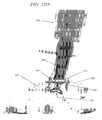
FIGS. 14 and 14A are pictorial views of a first illustrative insertion instrument;
FIG. 14B is a detailed view of the distal tip of the insertion instrument shown in FIGS. 14 and 14A;
FIG. 14C is a detailed view of the distal tip of the insertion instrument shown in FIGS. 14 and 14A in operative engagement with an interspinous spacer;
FIG. 14D shows a visual scale disposed in the insertion instrument shown in FIGS. 14 and 14A;
FIG. 14E illustrates the deployment positions of an interspinous spacer indicated by the visual scale shown in FIG. 14D;
FIG. 14F is a pictorial view of a second illustrative insertion instrument;
FIG. 14G is a detailed view of a load/deploy indicator disposed in the insertion instrument shown in FIG. 14F;
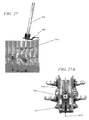
FIG. 15 is a pictorial view of an illustrative ligament splitter;
FIG. 15A is a detailed view of the distal end of the ligament splitter shown in FIG. 15;
FIGS. 16, 17, 18, 19 and 20 are illustrations which show various anatomical locations having relevance to the present tooling and procedure for implanting an interspinous spacer;
FIGS. 21 and 21A comprise a flowchart of an illustrative procedure for implanting an interspinous spacer using the tooling shown in FIGS. 3 to 15;
FIG. 22 is a pictorial view of the illustrative target needle of FIGS. 3 and 3A as inserted through the supraspinous ligament;
FIG. 22A is a detailed view of the distal end of the target needle showing its approximately centralized position between the superior and inferior spinous processes;
FIG. 23 is a detailed view of the target needle as inserted to an appropriate depth;
FIG. 23A is a detailed view of the illustrative K-wire of FIG. 4 as inserted through the target needle;
FIG. 23B is a detailed view of the alignment of the K-wire to the target needle;
FIG. 24 is a pictorial view of an optional use of the illustrative K-wire clamp of FIG. 5 during positioning of the K-wire;
FIG. 25 is a pictorial view of the first illustrative dilator shown in FIG. 6 as inserted through the supraspinous ligament;
FIG. 25 a is a detailed view of the first illustrative dilator as inserted through the supraspinous ligament to an appropriate depth;
FIG. 26 is a pictorial view of the second illustrative dilator shown in FIG. 7 as inserted through the supraspinous ligament;
FIG. 26A is a detailed view of the second illustrative dilator as inserted through the supraspinous ligament to an appropriate depth;
FIG. 26B is a detailed view of the alignment of the first dilator to the second dilator;
FIG. 27 is a pictorial side view of the mounting bracket shown in FIGS. 8, 8A, 8B and 8C as inserted over the second dilator;
FIG. 27A is top view of the mounting bracket and dilator with respect to the mid-line of the spine;
FIG. 27B is a pictorial view of an illustrative docking tower being loaded over the dilator;
FIG. 27C is a side view of the docking tower and dilator showing a preferred trajectory with respect to the supraspinous ligament and spinous processes;
FIG. 27D is a view of the docking tower and dilator with respect to the mid-line of the supraspinous ligament;
FIG. 27E is a view of the docking tower in a deployed position;
FIG. 27F is a detailed side view of the docking tower and dilator showing the positioning of the distal end of the dilator just past the anterior side of the supraspinous ligament;
FIG. 28 is a pictorial side view of the cannula shown in FIGS. 9, 9A and 9B as inserted through the mounting bracket and over the dilators;
FIG. 28A is a detailed view of the distal end of the cannula showing the alignment of the end channels with the spinous processes;
FIG. 28B is a detailed side view of the distal end of the cannula with respect to the distal end of the dilator, supraspinous ligament, and spinous processes;
FIG. 28C is a pictorial view of the mounting bracket and cannula showing the locking orientation of a rotating nut;
FIG. 28D is a pictorial view of the mounting tower, cannula and dilator;
FIG. 29 is a pictorial view of the interspinous knife shown in FIGS. 11, 11A and 11B as inserted into the cannula;
FIG. 29A is a detailed view of the initial cut pattern and the orientation of the interspinous knife with respect to the cannula;
FIG. 29B is a detailed view of an optional cut pattern that is oriented 45 degrees from the initial cut through rotation of the interspinous knife with respect to the cannula;
FIG. 30 is a pictorial view of the first illustrative interspinous gauge shown in FIGS. 13 and 13A making a measurement of the interspinous space between the superior and inferior spinous processes;
FIGS. 30A and 30B are pictorial views of the second illustrative interspinous gauge shown in FIGS. 13B, 13C and 13D;
FIGS. 31A-F are pictorial views of an interspinous spacer in a variety of positions;
FIG. 31G is a pictorial view of the insertion instrument of FIGS. 14, 14A, 14B, 14C, 14D showing operation of the handle which rotates a shaft in the elongated tube;
FIG. 31H is a detailed view of the distal end of the elongated tube of the insertion instrument with rotatable shaft;
FIG. 31I shows a visual scale disposed in the insertion instrument shown in FIGS. 31G and 31H;
FIGS. 31J and 31K are pictorial views of an illustrative interspinous spacer in operative engagement with the insertion instrument shown in FIGS. 31G and 31H;
FIG. 32 is a detailed view of a flat portion of the insertion instrument in alignment with a flat surface of the cannula that sets a depth indicator of “zero”;
FIG. 32A is a pictorial view of the insertion instrument with loaded interspinous spacer as inserted through the cannula;
FIG. 32B is a pictorial view of the insertion instrument of FIGS. 14F and 14G in operative engagement with an interspinous spacer as placed into the interspinous space in an undeployed position;
FIG. 32C is a pictorial view of the insertion instrument of FIGS. 14F and 14G in operative engagement with an interspinous spacer as placed into the interspinous space in a deployed position;
FIG. 33 is a pictorial view of an interspinous spacer as deployed; and
FIG. 34 is a pictorial representation of an image that shows the interspinous spacer as deployed.
DETAILED DESCRIPTION
Before the subject devices, systems and methods are described, it is to be understood that this invention is not limited to particular embodiments described, as such may, of course, vary. It is also to be understood that the terminology used herein is for the purpose of describing particular embodiments only, and is not intended to be limiting, since the scope of the present invention will be limited only by the appended claims.
Unless defined otherwise, all technical and scientific terms used herein have the same meaning as commonly understood by one of ordinary skill in the art to which this invention belongs.
It must be noted that as used herein and in the appended claims, the singular forms “a”, “an”, and “the” include plural referents unless the context clearly dictates otherwise. Thus, for example, reference to “a spinous process” may include a plurality of such spinous processes and reference to “the marker” includes reference to one or more markers and equivalents thereof known to those skilled in the art, and so forth.
Where a range of values is provided, it is understood that each intervening value, to the tenth of the unit of the lower limit, unless the context clearly dictates otherwise, between the upper and lower limits of that range is also specifically disclosed. Each smaller range between any stated value or intervening value in a stated range and any other stated or intervening value in that stated range is encompassed within the invention. The upper and lower limits of these smaller ranges may independently be included or excluded in the range, and each range where either, neither or both limits are included in the smaller ranges is also encompassed within the invention, subject to any specifically excluded limit in the stated range. Where the stated range includes one or both of the limits, ranges excluding either or both of those included limits are also included in the invention.
All publications mentioned herein are incorporated herein by reference to disclose and describe the methods and/or materials in connection with which the publications are cited. The publications discussed herein are provided solely for their disclosure prior to the filing date of the present application. Nothing herein is to be construed as an admission that the present invention is not entitled to antedate such publication by virtue of prior invention. Further, the dates of publication provided may be different from the actual publication dates which may need to be independently confirmed.
The present invention will now be described in greater detail by way of the following description of exemplary embodiments and variations of the devices and methods of the present invention. The invention generally includes a group of tools arranged for the percutaneous implantation of an interspinous spacer using an inventive method. A key feature of the interspinous spacer device is that it is expandable from a low profile configuration to a higher profile or operative configuration. This design allows the device, when in the low profile condition, to be delivered percutaneously through use of the tooling without requiring the removal of any portion of the spinal motion segment into which the device is implanted.
Each of the tools shown in the FIGs and described in the accompanying text are advantageously used as part of as a tooling system to perform the inventive method. That is, the tools are arranged to be used as a group—each tool in combination with others and/or sequentially as described in detail below. Accordingly, the tools generally are configured with coordinated markings and/or features to enable the tools to be used cooperatively and to ensure consistency of operation during the implantation procedure. For example, as noted above and without limiting the invention, each of the tools is arranged with coordinated markings and/or other features to ensure consistent depths of insertion, proper orientation of the tools with respect to each other or an anatomical feature of the patient, and precise delivery of the spacer to maintain safe positioning throughout the implantation procedure.
However, while use of the tools as a tooling system is preferable in some applications of the invention, it is emphasized that each tool may also be beneficially and advantageously utilized alone or in subset combination with other tools, but without using all of the tools in the tooling system. Thus while the utilization of the entire set of tools in the tooling system is often beneficial in many applications, it is not mandatory.
In addition, each of the tools shown in the FIGs and described in the accompanying text are advantageously utilized to perform the inventive percutaneous spacer implantation in a minimally invasive manner so as to minimize the affect of the procedure on the patient's tissues and, in particular, the supraspinous ligament. Utilization of such minimally invasive techniques can shorten the procedure's time and speed recovery by the patient. However, the application of the tools in a minimally invasive manner is not a requirement in order to realize many of the benefits provided by the tooling.
Referring now to FIGS. 3 and 3A, pictorial views of an illustrative target needle 305 and inner puncher 312 are respectively provided. The target needle 305 and inner puncher 312, when assembled (e.g., locked) together, function to place a guidewire (e.g., a K-wire) through the patient's skin into an area which neighbors a vertebral segment of interest. Accordingly, target needle 305 and inner puncher 312 are configured to penetrate the supraspinous ligament and other tissue. Target needle 305 and inner puncher 312 are preferably disposable tools (i.e., arranged as single use instrumentalities in most applications of the invention).
Both the target needle 305 and inner puncher 312 are arranged with graspers on the proximal ends as indicated by reference numerals 318 and 321. Target needle 305 further includes wings 325 that are arranged to facilitate gripping of target needle 305 by an operator.
Target needle 305 includes a hollow needle portion 327 that is arranged to removably receive a needle portion 330 of the inner puncher 312, typically in a close-fitting manner. That is, the outside diameter of the needle portion 330 is sufficiently close in dimension to the inner diameter of the hollow needle portion 327 so that the inner puncher 312 is substantially radially fixedly positioned once needle portion 330 completes its slideable engagement with hollow needle portion 327. Both the hollow needle portion of target needle 305 and the needle portion 330 of inner puncher 312 are preferably composed of stainless steel for most applications of the invention and are thus configured to be visible using fluoroscopy to assist insertion to the desire depth. The inner diameter of target needle 305 is further selected to allow the removable insertion of a guidewire.
Target needle 305 and inner puncher 312, in this illustrative example, are further configured with a positive attachment comprising a threaded-type connection or, as shown in FIGS. 3 and 3A, a rotatably engagable bayonet-type lock. In this arrangement, a pin 321 radially extends from a distal portion of the target needle 305. Pin 321 rotatably lockably engages with a mating slot 336 disposed in a lower portion of the grasper 321 when the inner puncher 312 is fully inserted through the needle portion 327 of target needle 305. When thus locked, the inner punch 312 is substantially fixedly radially and axially located within target needle 305. By anti-rotating the inner punch 312 with respect to the target needle 305, the inner punch 312 is unlocked so it can be removed from the target needle 305.
Inner puncher 312 includes a sharpened portion 335 at the distal end of the needle portion 330 as shown. The needle portion 330 of inner puncher 312 is configured (i.e., has sufficient length) so that the sharpened portion 335 is exposed when the inner puncher 312 is inserted into the hollow needle portion 327 of the target needle 305 and locked into position.
In an optional arrangement for the target needle 305, an energy delivery functionality is provided whereby an energy delivery unit (not shown) such as an RF (radio frequency) unit is operatively coupled to the distal end of the target needle 305 and/or inner puncher 312. Such energy delivery functionality may be utilized to assist with skin or other tissue penetration or blood coagulation, for example.
In another optional arrangement, target needle 305 and/or inner puncher 312 are arranged with one or more markers such as ultrasonic, magnetic, or other types of markers. Use of such markers may advantageously reduce or eliminate the need for fluoroscopic imaging in some applications of the invention.
FIG. 4 is a pictorial view of an illustrative K-wire 402 that is arranged to be inserted through the target needle 305 (FIG. 3) after the inner punch 312 (FIG. 3) is unlocked and removed. K-wire 402 functions to allow one or more devices to be placed over it to a particular anatomical location. K-wire 402 includes a groove 406 which is also shown in the detailed view of FIG. 4A. Groove 406 is arranged as a circumferential notch in most applications of the invention and provides for depth placement on a matched basis among the one or more devices. Accordingly, groove 406 is spaced at a specific depth relative to the end of the target needle 305.
K-wire 402 is constructed from stainless steel in a similar manner to conventional guidewires. K-wire 402 may alternatively include other depth markings such as circumferential markers (not shown) or be arranged to be radiopaque (i.e., not allow X ray or other radiation to penetrate) or include radiopaque sections. K-wire 402 is preferably arranged as a disposable or single-use tool.
In an optional arrangement for K-wire 402, a circumferential band 412 is disposed along its length as shown in FIG. 4B. Circumferential band 412 provides for depth placement in a similar manner as groove 406, and may also be utilized to perform as a mechanical stop to limit the advancement of the K-wire 402 through the target needle 305.
In another optional arrangement, K-wire 402 is arranged with one or more markers such as ultrasonic, magnetic markers or other marker types, for example, to avoid the need for fluoroscopy.
FIG. 5 is a pictorial view of an illustrative K-wire clamp 505 that, when placed by an operator on a guidewire such as K-wire 402 (FIG. 4) near the tissue entry site, functions to stabilize the guidewire. Such stabilization may be helpful to prevent further insertion of the guidewire beyond a desired depth and unwanted inadvertent movement of the guidewire.
K-wire clamp 505 is generally configured in a hinged clamp arrangement in most applications of the invention in which each clamp portion is biased with a spring (e.g., a torsional spring) to provide a desired level of clamping pressure on the guidewire. K-wire clamp 505 is preferably arranged as a disposable or single-use tool.
In an optional arrangement for K-wire clamp 505A, a slip sensor 510 and/or alarm transducer 517 are disposed along portions of the K-wire clamp 505 as shown in FIG. 5A. If slippage (i.e., relative movement between the K-wire clamp 505 and the guidewire) beyond a predetermined threshold is detected by slip sensor 510, then a signal over signal path 522 triggers the alarm transducer 517 to transmit an alarm to an alarm receiving location or alarm monitor (not shown). In such optional arrangement, K-wire clamp 505A provides a positive indication such as a visual indicator (e.g., activation of a light source such as a light emitting diode) or audible alarm (e.g., activation of a tone generator or buzzer) in the event that the K-wire clamp is inadvertently opened (either completely or partially) or the guidewire slips. Slip sensor 510 is alternatively arranged as a magnetic sensor or electrical/resistance-sensing sensor, for example.
Referring to FIGS. 6, 6A, 7 and 7A, pictorial and detailed views of two illustrative dilators are shown. FIG. 6 is a pictorial view of a first illustrative dilator 605 that is arranged with a through channel that slidably engages with a guidewire such as K-wire 402 (FIG. 4) and is inserted through the supraspinous ligament. When used alone or in combination with the second illustrative dilator 705 shown in FIGS. 7 and 7A, dilator 605 progressively (or sequentially) dilates tissue to thereby enable insertion of devices through the dilated opening.
Dilators 605 and 705 are preferably radiopaque and arranged as disposable, single use tools in most applications of the invention. Dilators 605 and 705 are typically constructed from stainless steel, titanium or similar materials. Dilator 605 includes a grip portion 607 at the proximal end, which in this illustrative example, is arranged as series of rings that alternate with recessed portions. Dilator 705 is arranged with a similar grip portion 707. A grip portion employing knurling or other material texturing may be alternatively utilized with either or both dilators 605 and 705 in some applications of the invention.
Dilator 605 includes a groove 611, for example a circumferential notch, that functions as a visible depth marker. Dilator 705 is similarly arranged with a groove 711. Dilators 605 and 705 may optionally include other markers such as ultrasonic, magnetic or other markers, for example, to avoid the need for fluoroscopy.
Dilator 605 is arranged, in this illustrative example, with a mid-line/orientation indicator such as a longitudinal groove 615 that is disposed substantially along the entire length of the dilator (i.e., from the proximal to distal end). Such mid-line/orientation indicator provides a visual marker that assists proper insertion of the dilator 605. Dilator 705 is also arranged with a longitudinal groove 715 in a similar manner.
Dilators 605 and 705 share similar construction and features but differ in size, notably inside and outside diameters (ID and OD, respectively). The respective diameters are selected such that dilator 605 and 705 are mateably and slidably engagable (i.e., in a telescoping manner). In this illustrative example, the OD of dilator 605 is 5 mm and the OD of dilator 705 is 9.3 mm.
Dilator 605 includes a tapered portion 621 at its distal end in which a spinous process channel 626 is disposed. The spinous process channel 626 is configured to align and/or mateably engage with a spinous process to thereby maintain a desired mid-line position of the dilator 605. In addition, the spinous process channel may be utilized to distract tissue whereby a forward force is applied. A scalloped leading edge 630 is optionally disposed at the tapered portion 621 of dilator 605 which is arranged to facilitate insertion of the dilator through the tissue while minimizing tissue trauma.
Dilator 705 also includes a tapered portion 721 and a spinous process channel 726 that are each configured in a similar manner as those corresponding features in dilator 605. A scalloped leading edge 730 is preferably included along the far distal end of dilator 705.
The tapered portions 621 and 721 of dilators 605 and 705, respectively, are preferably sized, when inserted, to end on the anterior side of the supraspinous ligament (which can be verified under fluoroscopy or other visualization means such as ultrasound). Such arrangement is intended to minimize damage to the supraspinous ligament since any trauma to underlying tissue is less consequential. Table 1 below provides illustrative key dimensions for dilators 605 and 705.
TABLE 1
Taper Taper Spinous Process Channel
Length Angle Channel Length Taper
Dilator
605 0.250 in. 27 degrees 0.225 in. 27 degrees
Dilator
705 0.570 in. 17 degrees 0.530 in. 15 degrees
Dilators 605 and 705 are each optionally arranged to include an energy delivery functionality using an operatively coupled energy delivery unit (not shown) such as an RF (radio frequency) unit. In most applications, the energy is delivered through the tip of the dilator to assist with tissue penetration or coagulation.
In an alternative arrangement, a third dilator (not shown) is also utilized. Such third dilator is intermediately-sized between dilator 605 and dilator 705. Accordingly, the third dilator is configured with appropriate inside and outside diameter dimensions to be slidably engaged over the OD of dilator 605 and slidably inserted into the ID of dilator 705, typically in a close-fitting arrangement.
In a second alternative arrangement, a longitudinally oriented, relatively narrow opening such as a slit (not shown) is disposed substantially along the length of dilator 605 and/or dilator 705. Such a feature enables the dilator to be removed from the guidewire without requiring the retraction of the full length of the guidewire. For example, the dilator can be simply removed by passing the guidewire through the longitudinal opening to thereby clear an object or device at the proximal end of the guidewire.
FIGS. 8, 8A, 8B and 8C show pictorial views of an illustrative mounting bracket 802 in various alternative arrangements. Mounting bracket 802 functions to create a stable working platform by holding an elongated device such as a cannula in a fixed position. Mounting bracket 802 is generally positioned over the dilator 705 (FIG. 7) prior to the insertion of a cannula. Alternatively, mounting bracket 802 may be positioned after the insertion of the cannula.
Mounting bracket 802 is typically further attached to a stabilizing device (such as that shown in FIG. 10) using a dual mounting slot arrangement 805 as shown in FIG. 8, or a single mounting slot 807 in base 809. The alternative mounting slot arrangements enable such a stabilizing device to be attached to the superior or inferior ends of mounting bracket 802 (using slot arrangement 805) or laterally (i.e., left or right, using the mounting slot 807). The other end of the stabilizing device is typically fixedly attached to a table or other immobile object. In addition to slots, mounting through-holes are alternatively utilizable for some applications. In alternative arrangements, mounting bracket 802 is configured for attachment directly to the patient (instead of, for example, a table-mounted stabilizing device) through use of adhesives or sutures for skin-mounting or via screws or other mechanical fasteners for bone-mounting.
Base 809 may be optionally arranged to include unique markings which, in this illustrative example, are arranged as dots 811. For example, radiopaque markings or conventional visible markings are usable to assist with alignment, depth control, or mating with other discrete devices or tools. Alternatively, the markings may be arranged using ultrasonic, magnetic or other marker-types, for example, to avoid the need for fluoroscopy.
Mounting bracket 802 thus facilitates the alignment of the cannula with the spine so that an operator may select a desired trajectory and orientation of the cannula into the tissue. That is, mounting bracket 802 with the associated stabilizing device provides positive control of axial, sagittal and coronal positioning of the interspinous spacer as implanted by the present procedure and tooling.
As shown in FIG. 8A, mounting bracket 802A includes a single threaded nut 813 that is rotatably coupled to an externally threaded cylinder 815 having a cylindrically shaped passageway through which the tool is inserted. Cylinder 815 includes one or more longitudinally oriented slots 818 (FIG. 8) that enable the walls of the cylinder 815 to move slightly radially inward to thereby provide a clamping force against the inserted tool when the nut 813 is tightened on the threads of the cylinder 815. The inner walls of the cylinder are optionally configured with projections or texturing to enhance the grip on the tool. Accordingly, nut 813 and cylinder 815 combine to form a receiving tube 820 that surrounds and clamps a portion of the tool's elongated element (which is generally a tubular element).
In FIG. 8B, mounting bracket 802B includes an alternative dual nut design using a primary threaded nut 813B and a secondary locking threaded nut 814. Primary nut 813B is first tightened to fixedly clamp the tool's elongated element in the receiving tube 820. Secondary nut 814 is then tightened to thereby lock the primary nut 813B in place. Other locking-type arrangements are also usable in some applications. For example, a nylon or other plastic insert (not shown) is disposed around the inner threaded portion of nut 813 to provide anti-rotation capabilities. A clutch-type mechanism (not shown) that slips upon reaching a predetermined torque or engagement travel may also be incorporated into the nut/cylinder arrangement. In addition, a positive locking arrangement such as push-to-turn or lift-to-turn (as commonly used in child-proof medicine containers) may be employed in the nut/cylinder mechanism in those applications where a positive lock and unlock feature is desirable.
Mounting bracket 802 is typically arranged, in most applications of the invention, with a semi-spherical projection 825 that is disposed on a bottom surface of the base 809 so that the spherical portion of the projection 825 projects substantially downward when mounting bracket 802 is oriented as shown in the FIGS. 8A and 8B. Projection 825 functions to substantially fill the area between the base 809 and the patient's tissue to thereby assist with stabilization of the mounting bracket 802. The semi-spherical shape of projection 825 provides for such stabilization while simultaneously allowing rotation about three axes (i.e., yaw, pitch and roll) to facilitate setting of the trajectory of a coupled tool such as a cannula.
Base 809 of mounting bracket 802 is arranged in a stepped, or dual plane, configuration in the illustrative example shown in FIGS. 8, 8A and 8B. Base 809 includes a planar portion 832 from which receiving tube 820 upwardly projects and a planar portion 835 in which the one or more mounting slots are disposed. Planar portions 832 and 835 are substantially parallel while being offset to thereby enable mounting bracket 802 to be aligned with the patient's body particularly when using a non-orthogonal tool trajectory. The combination of the dual plane configuration with use of the projection 825 is particularly advantageous in many applications of the invention to provide stability for the mounting bracket 802 over a range of tool trajectories.
An alternative configuration for the mounting bracket is shown in FIG. 8C. There, mounting bracket 802C employs an angled base 809C that may provide additional flexibility for aligning mounting bracket 802C with the body in some applications of the invention.
Mounting bracket 802 is preferably radiopaque and arranged as a disposable, single use tool in most applications of the invention. Mounting bracket 802 is generally preferred to be of rigid construction to provide for stable orientation of the coupled tool. In most applications of the invention, base 809 is constructed of aluminum with the nut 813 and cylinder 815 being formed from radiopaque plastic such as polyphenylsulfone thermoplastic (sold under the brand Radel® R). Markers 811, when arranged as radiopaque markers, are formed using stainless steel.
In an alternative arrangement, mounting bracket 802 is configured with more than one receiving tube 820 (i.e., more than one nut/cylinder combinations). The other receiving tubes (not shown) may fixedly clamp other tools, instruments or devices such as a laparoscopic camera or light. The other receiving tubes may be oriented with the same trajectory as receiving tube 820, or be oriented orthogonally or at some other trajectory with respect to receiving tube 820.
FIGS. 8D and 8E show pictorial views of an illustrative mounting tower 850. Mounting tower 850 is used as an alternative to mounting bracket 802 and similarly functions to create a stable working platform by holding an elongated device such as a cannula in a fixed position. Mounting tower 850 is generally positioned over the dilator 705 (FIG. 7) prior to the insertion of a cannula.
Mounting tower 850 is typically further attached to a stabilizing device (such as that shown in FIG. 10) using a dual mounting slot arrangement 855 in a base 858 as shown in FIGS. 8D and 8E, or alternatively using a single mounting slot or a plurality of mounting slots, i.e., three or more (not shown). The alternative mounting slot arrangements enable such a stabilizing device to be attached to the superior or inferior ends of mounting tower 850 (using slot arrangement 855) or laterally (i.e., left or right, using a mounting slot 855). The other end of the stabilizing device is typically fixedly attached to a table or other immobile object. In addition to slots, mounting through holes are alternatively utilizable for some applications. In alternative arrangements, mounting tower 850 is configured for attachment directly to the patient (instead of, for example, a table-mounted stabilizing device) through use of adhesives or sutures for skin-mounting or via screws or other mechanical fasteners for bone-mounting.
Mounting tower 850 includes a pointing arrow 861 (such as a Cephalad indicator) that, in this illustrative example, is integrally formed with and laterally extending from base 858.
Mounting tower 850 is arranged with two pairs of spinous process grippers indicated by reference numerals 864 and 866 in FIGS. 8D and 8E. Each spinous process gripper pair comprises two longitudinally extending, opposing, pivotally-mounted legs. Opposing gripping surfaces are disposed at the distal ends of the legs and are arranged with a plurality of laterally inwardly extending serrated edges 869 in FIG. 8G. When the mounting tower 850 is in a fully deployed condition, spinous process grippers 864 are arranged to clamp to the superior spinous process and spinous process grippers 866 clamp to the inferior spinous process.
Mounting tower 850 further includes a superior depth post 870 and an inferior depth post 871 which project axially downward from the base 858. Superior depth post 870 is disposed substantially between the legs of spinous process gripper 864. Inferior depth post 871 is disposed substantially between the legs of spinous process gripper 866. Posts 870 and 871 function as depth stops. Thus, posts 870 and 871 are arranged to interface with the posterior side of the supraspinous ligament so as to thereby limit the travel of the mounting tower 850 and position the spinous process grippers 864 and 866 in an appropriate orientation with respect to the spinous processes. In this illustrative example, inferior depth post 871 is shorter than superior depth post 870 so as to provide some angular freedom of motion in the plane including the longitudinal axis of the supraspinous ligament.
Mounting tower 850 thus facilitates the alignment of the cannula and subsequently utilized tools or devices with the spine so that an operator may select a desired trajectory and orientation of the cannula into the tissue. That is, mounting tower 850 with the associated stabilizing device provides positive control of axial, sagittal and coronal positioning of the interspinous spacer as implanted by the present procedure and tooling.
Mounting tower 850 includes a rotatably-mounted lower cylindrically-shaped collar 872 that extends axially upwards from base 858. Collar 872 rotates about a spindle 873 having a receiving tube (i.e., lumen) therethrough. Collar 872 is operatively coupled using a linkage that is internally disposed in mounting tower 850 to the spinous process grippers 864 and 866. Collar 872 is biased against an internally disposed spring to hold the collar 872 against an internally disposed stop. The stop prevents rotation of the collar 872 until the collar 872 is pushed axially downward against the spring bias to thereby disengage from the stop and rotate freely.
Collar 872 includes surface features, for example knurling, to enhance the operator's grip on the collar 872 when being manipulated.
An internally disposed spring normally biases the spinous process grippers 864 and 866 outwardly as indicated by Position 1 in FIG. 8H. The internal linkage is arranged so that rotation of the collar 872 causes movement of the spinous process grippers 864 and 866. In particular, clockwise rotation (when looking axially downward from the orientation of the mounting tower 850 shown in the figures) of collar 872 causes relative inward motion of spinous process grippers 864 with respect to spinous process grippers 866 as indicated by the arrows in FIG. 8H until the spinous process grippers 864 and 866 reach Position 2. As shown, the direction of motion of the spinous process grippers 864 and 866 are in planes which are substantially parallel to the line 874 defined by the longitudinal axis of pointing arrow 861 (i.e., Cephalad indicator).
Clockwise rotation of collar 872 further causes relative outward motion of the opposing legs in each pair of the spinous process grippers 864 and 866 as indicated by the arrows in FIG. 8I. As shown, the direction of motion of each of the opposing legs are in planes that are substantially perpendicular to the line 874 which is defined by the longitudinal axis of pointing arrow 861 (i.e., Cephalad indicator).
Typically, collar 872 is rotated clockwise to place the pairs of spinous process grippers 864 and 866 into a “ready” position prior to deployment. That is, the above-described inward motion of the spinous process grippers 864 and 866 reduces the size of the incision required to pass the spinous process grippers 864 and 866 into the operative position with respect to the spinous processes. In addition, the above-described outward motion of the legs in each pair of spinous process grippers 864 and 866 ensures that a sufficient distance “D,” as indicated in FIG. 8I, is obtained for the legs to pass over the entire width of the supraspinous ligament as is required to clamp to the spinous processes.
FIG. 8J shows the position of the spinous process grippers 864 and 866 as placed in the ready position through clockwise rotation of collar 872 and positioned over the supraspinous ligament 875. Rotation of the collar 872 in a counterclockwise direction allows the spinous process grippers 864 and 866 to return to their normal outwardly-disposed position as shown in FIG. 8K.
Mounting tower 850 further includes a rotatably-mounted upper cylindrically-shaped collar 880 as shown in FIGS. 8D-G and FIG. 8L that is axially disposed above collar 872. In this illustrative example, the upper collar 880 is arranged to have a slightly larger diameter than lower collar 875 to thereby allow the upper collar 880 to be disposed in a partially overlapping annular manner with respect to the lower collar 875. Collar 880 is arranged in a similar manner as collar 872 with surface features, such as knurling, to enhance gripping by the operator.
Collar 880 is threadedly engaged with the spindle 873 Clockwise rotation of collar 880 thus causes the spindle 873 to move axially upwards with respect to the collar 880. An internally disposed linkage couples spindle 873 to the spinous process grippers 864 and 866 and is configured so that the axial upward motion of the spindle 873 causes the opposing legs in each spinous process gripper to move inwards and clamp the spinous processes, i.e., the superior spinous process 881 and inferior spinous process 882. Continued clockwise rotation of collar 880 by the operator functions to put sufficient clamping force “F,” as shown in FIG. 8L, on the spinous processes (collectively designated by reference numeral 884) by the spinous process grippers 864 and 866 to thereby hold the mounting tower 850 securely to the patient's spine.
In alternative arrangements, mounting tower 850 may be arranged with a single set of spinous process grippers or more than two pairs of spinous process grippers. In addition, while rotatably-configured actuation is often preferable, other mechanisms including levers and other linear-type actuators are also usable. Mounting tower arrangements using multiple receiving tubes are also contemplated as being desirable in some applications.
Mounting tower 850 is beneficially arranged, in most applications, as a reusable, or multiple-use tool. Mounting tower 850 is generally preferred to be of rigid construction to provide for stable orientation of the coupled tool. In most applications, mounting tower 850 utilizes metal construction.
Mounting tower 850 may be optionally arranged to include unique markings. For example, radiopaque markings or conventional visible markings are usable to assist with alignment, depth control, or mating with other discrete devices or tools. Alternatively, the markings may be arranged using ultrasonic, magnetic or other marker-types, for example, to avoid the need for fluoroscopy.
FIGS. 9, 9A and 9B are side, and two perspective views, respectively, of an illustrative cannula 903. Cannula 903 is arranged to be fixedly attached (i.e., clamped) in mounting bracket 802 (FIG. 8) to ensure proper orientation of the cannula 903 and delivery of the interspinous spacer in a desired manner. An internal lumen 906 in cannula 903 allows implants such as the interspinous spacer to pass through and is further configured in diameter and length to mate with devices and the present tools. Such mating may be performed in a fixed arrangement using a clamp or other removably coupling device (not shown). Cannula 903 thereby provides alignment and depth control, for example, via mechanical surfaces, visual markers and other indicators as described below. Cannula 903 may also be used, in some applications of the invention, to distract (i.e., push forward) the spinous processes or tissue. It is noted that the ID of the cannula 903 will typically vary according to the size of the interspinous spacer being implanted.
Cannula 903 is preferably arranged as a disposable, single use tool in most applications of the invention. Cannula 903 is typically constructed from a metal elongated tube 909 and includes a pointing arrow 912 (such as a Cephalad indicator) at the proximal end that provides a reference orientation along the mid-line towards the head. Cannula 903 includes a tapered tip 915 at the distal end.
The proximal end further includes a counterbore 918 that extends partially longitudinally inward (towards the distal end of cannula 903) and a flat 921 disposed on the inside wall of cannula 903 formed by the counterbore 918. Counterbore 918 and flat 921 are examples of mechanical surfaces disposed on or within cannula 903 that function to provide visual or mechanical alignment. For example, counterbore 918 and flat 921 provide alignment for devices or tools that are subsequently inserted into cannula 903 and/or provide a fixed insertion depth.
Tapered tip 915 includes one or more tapered spinous process channels 924 which are configured to align and/or mateably engage with a spinous process to thereby maintain a desire position of the cannula 903. In addition, the spinous process channels 924 may be utilized to distract tissue whereby a forward force is applied. A scalloped leading edge 930 is preferably disposed at the tapered tip 915 which is arranged to facilitate insertion of the cannula 903 through the tissue while minimizing tissue trauma. In particular, the scalloped leading edge 930 may help to part the supraspinous ligament, for example, using a rotating motion of cannula 903. Table 2 below provides illustrative key dimensions for cannula 903.
TABLE 2
Taper Taper Spinous Process Channel
Length Angle Channel Length Taper
Cannula
903 0.100 in. 24 degrees 0.475 in. 6 degrees
Tapered tip 915 may be optionally arranged with an energy delivery functionality using an operatively coupled energy delivery unit (not shown) such as an RF (radio frequency) unit. In most applications, the energy is delivered through the tapered tip 915 of cannula 903 to assist with tissue penetration or coagulation.
As an alternative to the pointing arrow 912 noted above, cannula 903 may include a longitudinal groove or marking that is disposed along the length, or a portion of the length of the elongated tube 909. In addition, cannula 903 is generally arranged to include unique markings, for example, radiopaque markings or conventional visible markings that are usable to assist with alignment, depth control, or mating with other discrete devices or tools. Alternatively, the markings may be arranged using ultrasonic, magnetic or other marker-types, for example, to avoid the need for fluoroscopy.
FIG. 10 is a pictorial view of an illustrative flexible stabilizing arm 1012. Stabilizing arm 1012 functions to stabilize one or more devices or tools with respect, for example, to the patient or operating table. Stabilizing arm 1012 further enables an operator to make adjustments to the position and trajectory of coupled devices or tools. The stabilizing arm 1012 is preferably arranged as a reusable, or multiple-use tool.
Stabilizing arm 1012 includes a first attachment element 1018 and a second attachment element 1021 as shown in FIG. 10. A flexible (i.e., articulating) portion 1025 couples the first and second attachment elements 1018 and 1021, respectively. As shown in FIG. 10, flexible portion 1025 comprises a plurality of individual ball and socket type elements that enable stabilizing arm 1012 to be manipulated by the operator into a variety of shapes and configurations that are maintained through friction between such elements. While other types of stabilizing arms (e.g., those having fewer degrees of freedom of motion) are also usable in many applications of the invention, a flexible stabilizing arm such as that shown in FIG. 10 is generally preferred.
First attachment element 1018 is arranged to be removably coupled to a tool or device holding device such as mounting bracket 802 (FIG. 8). As shown in FIG. 10, first attachment element 1018 comprises a threaded screw 1028 having a plurality of gripping ridges 1030 extending radially outward to facilitate threaded screw 1028 to be tightened by hand (i.e., without requiring the use of tools) into the screw receiving portion 1033 of first attachment element 1018. Screw shank 1036 is arranged to engage with a slot or through-hole in mounting bracket 802 to thereby fixedly and removably hold the mounting bracket 802 to the stabilizing arm 1012 when the screw 1028 is tightened.
Second attachment element 1021 is configured for removably or non-removably coupling to a fixture such as an operating table, bed or other fixed or relatively immobile object. For example, second attachment element 1021 is attached to an operating table using mechanical fasteners such as screws or bolts inserted through holes or slots (not shown) in second attachment element 1021. In an alternative arrangement, second attachment element 1021 is configured for attachment directly to the patient (instead of the operating table as provided in the example above) through use of adhesives or sutures for skin-mounting or via screws or other mechanical fasteners for bone-mounting.
In another alternative arrangement, a third attachment element (not shown) is utilized. The third attachment element is disposed between the first attachment element 1018 and second attachment element 1021. Or, the second attachment element 1021 may be disposed between the first attachment element 1018 and the third attachment element. Such a third attachment element advantageously enables, for example, two mounting brackets (such as mounting bracket 903 in FIG. 9) to be presented on a single stabilizing arm.
FIG. 11 is a pictorial view of a first illustrative interspinous knife 1102 which functions to cut through tissue to enable the percutaneous access associated with the subsequent implantation of an interspinous spacer. Interspinous knife 1102 provides a plunge cut-type action through the mechanical manipulation of a plunger 1107 by the operator in a pushing motion, typically by depressing the plunger 1107 with the thumb while gripping the handle portions 1109 with the fingers. The plunge depth is both controlled and adjustable in this illustrative example as described below.
As shown in the detailed view of FIG. 11A, the plunger includes an elongated inner tube 1110 which is rotatably located in the elongated outer tube 1115 of interspinous knife 1102 to thereby enable the operator to make rotations of the cutting blades 1117 disposed at the distal end of the inner tube 1110. As shown, blades 1117 are configured in an “X” pattern, but other blade counts (including a single blade) and patterns are usable depending on the specific requirements of an application of the invention.
Inner tube 1110 is arranged for slideable excursion through the outer tube 1115 to effectuate the plunge cutting action. In various alternative arrangements, plunger 1107 is biased against a spring force provided by a spring element (not shown) or is provided with a linear actuator such as a pneumatic actuator or spring loaded actuator. In another alternative arrangement, the plunge cut action is supplied with a mechanical advantage to increase cutting force. For example, a cam or lever type mechanism (not shown) may be utilized to increase the force applied by the blades 1117 by having the operator manipulate an actuating portion of the plunger through an increased distance.
A depth setting slide 1120 is disposed along a top surface of the handle portions 1109 of interspinous knife 1102 as shown in FIGS. 11 and 11B. Depth setting slide 1120 is arranged to move laterally in a sliding motion from a first position as shown in FIG. 11 to a second position as shown in FIG. 11B. When the depth setting slide 1120 is in the first position, the plunge depth of the plunger 1107 is limited to nominally 15 mm. When in the depth setting slide 1120 is in the second position, the plunge depth of the plunger 1107 is limited to nominally 20 mm. It is emphasized that such plunge depth settings are illustrative and other plunge depths may be selected according to the specific requirements of an application of the invention.
Interspinous knife 1102 is preferably arranged as a disposable, single use tool in most applications of the invention. Blades 1117 are constructed from stainless steel in most applications of the invention. The remaining components of interspinous knife 1102—including inner tube 1110, outer tube 1115, plunger 1107 and depth setting slide 1120—are generally formed from a polymeric material (i.e. plastic) such as a biocompatible plastic.
In the illustrative example shown in FIGS. 11, 11A and 11B, the inner tube 1110 is arranged to be rotated in an indexed manner. That is, the magnitude of rotation angles and the number of rotated positions of the inner tube 1110 are constrained with respect to outer tube 1115. In other applications, an infinitely rotatable inner tube 1110 is utilizable. It may be particularly beneficial in some applications for an initial plunge cut to be performed followed by a second plunge cut after the blades 1117 are rotated at an angle of 45 degrees to the initial plunge cut.
Interspinous knife 1102 includes a widened shoulder feature 1121 that is configured to engage with the counterbore 918 and flat 921 in cannula 903 (FIG. 9) when the interspinous knife 1102 is inserted through the lumen 906. Such engagement between the shoulder feature and counterbore/flat thereby locates and aligns the interspinous knife 1102 at the proper depth and orientation with respect to the cannula 903 and the spine.
Interspinous knife 1102 is typically arranged with radiopaque or conventional visible markings that are usable to assist with alignment, depth control, or mating with other discrete devices or tools. For example, such markings can be used to indicate the longitudinal position (i.e., plunge depth) or orientation (i.e., rotation angle) of the blades 1117. Alternatively, the markings may be arranged using ultrasonic, magnetic or other marker-types, for example, to avoid the need for fluoroscopy.
Interspinous knife 1102 may be optionally arranged with an energy delivery functionality using an operatively coupled energy delivery unit (not shown) such as an RF (radio frequency) unit. In most applications, the energy is delivered through the blades 1117 to assist with tissue penetration or coagulation.
FIG. 11C is a pictorial view of a second illustrative interspinous knife 1130 which functions to cut through tissue to enable the percutaneous access associated with the subsequent implantation of an interspinous spacer. Interspinous knife 1130 is usable to supplement interspinous knife 1102 (FIG. 11) or as an alternative to interspinous knife 1102.
Interspinous knife 1130 includes a semi-spherical depth stop 1135 that is integrally disposed in a handle 1138. Depth stop 1135 is sized and arranged to interface with the counterbore 918 (FIG. 9) in cannula 903 to thereby limit the cutting depth of interspinous knife 1130. Shaft 1141 is sized in length to place the cutting blade 1145 at a predetermined distance from the depth stop 1135. Shaft 1141 is sized so that cutting blade 1145 cuts to a nominal depth “D” of 15 mm, as indicated in FIG. 11D, from the anterior side of the supraspinous ligament 875. Alternatively, shaft 1141 is sized so that cutting blade 1145 cuts to a nominal depth of 20 mm.
Operation of the interspinous knife 1130 includes articulation of interspinous knife 1130 in cannula 903. In addition to a plunge-type cut that is depth controlled by the depth stop 1135, interspinous tissue is also cut by levering the handle 1138 so that the interspinous knife pivotally rotates about the semi-spherically shaped depth stop as a fulcrum. The distal end of the interspinous knife thus sweeps through an arc so that the cutting blade 1145 is movable through a range of positions including that indicated by 1145′ in FIG. 11D.
Interspinous knife 1130 is preferably arranged as a disposable, single use tool in most applications of the invention. Cutting blade 1145 and shaft 1141 are constructed from stainless steel in most applications of the invention. The depth stop 1135 and handle 1138 of interspinous knife 1130 are generally formed from plastic such as a biocompatible plastic.
FIGS. 12, 12A, 12B and 12C show various views and features of a first illustrative interspinous reamer 1201 and its constituent components. Interspinous reamer 1201 is an optionally utilized tool in the tooling set described herein and functions to create a channel through which an interspinous spacer is inserted by removing bone and other tissue when required. Interspinous reamer 1201 is configured to remove both tough tissues including bone, as well as soft tissues. Interspinous reamer 1201 enables percutaneous access in combination, for example, with the mounting bracket 802 (FIG. 8) and cannula 903 (FIG. 9).
Interspinous reamer 1201 is configured to perform a tissue removal with a fixed diameter to thereby minimize damage to non-targeted tissue. Such diameter is preferably selected according to the size of the interspinous spacer being utilized. Interspinous reamer 1201 is further configured for controlled depth of penetration as described below.
Interspinous reamer 1201 uses a two-piece construction comprising a core cutter 1208, as shown in FIG. 12, and a hole cutter 1212, as shown in FIG. 12A. Core cutter 1208 is inserted into hole cutter 1212 to thereby form the interspinous reamer 1201 as shown in FIGS. 12B and 12C. FIG. 12B shows the core cutter 1208 being fully inserted into hole cutter 1212, while FIG. 12C shows the core cutter 1208 being partially inserted into the hole cutter 1212.
The interspinous reamer 1201 is generally operated in a two-step process. A hole cut is made into the target tissue using hole cutter 1212 which is followed by a core cut by the core cutter 1208 which evacuates the tissue from the tube of the hole cutter 1212.
Core cutter 1208 is comprised of a flat bottom drill bit having a sharpened tip 1215 and a forward serrated circumferential edge 1218. An evacuation port 1221 is disposed on the face of core cutter 1208. A spiral evacuation channel 1227 is disposed at the exit of the evacuation port 1221 for transporting removed tissue away from the working channel in the tissue when the interspinous reamer 1201 is coupled to a drill (such as a conventional bone drill, not shown) and rotated. Interspinous reamer 1201 is alternatively arranged to have an integrally incorporated drill or to be coupled to a drill in a conventional manner.
Hole cutter 1212 is arranged as an elongated tube having a sharpened distal end, for example, arranged as a forward serrated circumferential edge 1230, as shown in FIG. 12A. A plurality of laterally disposed holes 1233 are arranged along the elongated tube of hole cutter 1212 to enable cleaning or evacuation of removed tissue into a cannula.
Core cutter 1208 and/or hole cutter 1212 are typically marked to allow for controlled penetration depth. Alternatively, core cutter 1208 and/or hole cutter 1212 can be constructed to include a mechanical lock or positive stop to physically limit or control penetration depth. For example, core cutter 1208 and/or hole cutter 1212 may include a lateral projection that positively engages with the counterbore 918 (FIG. 9B) in cannula 903 (FIG. 9) to function as a stop to limit penetration beyond a predetermined depth.
Interspinous reamer 1201 is typically arranged with radiopaque or conventional visible markings that are usable to assist with alignment, depth control, or mating with other discrete devices or tools. Alternatively, the markings may be arranged using ultrasonic, magnetic or other marker-types, for example, to avoid the need for fluoroscopy.
Interspinous reamer 1201 may be optionally arranged with an energy delivery functionality using an operatively coupled energy delivery unit (not shown) such as an RF (radio frequency) unit. In most applications, the energy is delivered through the distal ends of core cutter 1208 and/or hole cutter 1212 to assist with tissue penetration or coagulation. In an alternative arrangement, interspinous reamer 1201 is configured as an over-the-wire tool using a centrally disposed lumen in the core cutter 1208.
In most applications, interspinous reamer 1201 is beneficially arranged as a reusable, or multiple-use tool.
FIG. 12D is a pictorial view of a second illustrative interspinous reamer 1225. As with the first illustrative interspinous reamer 1201 shown in FIGS. 12, 12A, 12B and 12C, interspinous reamer 1225 is an optionally utilized tool in the tooling set described herein and functions to create a channel through which an interspinous spacer is inserted by removing bone and other tissue when required. Interspinous reamer 1225 is configured to remove both tough tissues including bone, as well as soft tissues. Interspinous reamer 1225 is usable to supplement interspinous reamer 1201 (FIGS. 12 and 12A-C) or as an alternative to the interspinous reamer 1201.
Interspinous reamer 1225 includes a substantially spherically-shaped handle 1228 that is disposed at the proximal end of an elongated shaft 1231. At the shaft's distal end, a substantially cylindrically-shaped cutting element 1235 is disposed. Cutting element 1235 includes a plurality of radially outwardly projecting teeth disposed around the cylinder's surface in multiple rows as shown in the detailed view of FIG. 12E.
Interspinous reamer 1225 includes semi-disc-shaped depth stop 1238 that is disposed between the handle 1228 and the proximal end of the shaft 1231. Depth stop 1238 is sized and arranged to interface with the counterbore 918 (FIG. 9) in cannula 903 to thereby limit the cutting depth of interspinous reamer 1225. Shaft 1231 is sized in length to place the cutting element 1235 at a predetermined distance from the depth stop 1238. Shaft 1231 is sized so that cutting element 1235 cuts to a nominal depth “D” of 15 mm, as indicated in FIG. 12F, from the anterior side of the supraspinous ligament 875.
Interspinous reamer 1225 is typically arranged with radiopaque or conventional visible markings that are usable to assist with alignment, depth control, or mating with other discrete devices or tools. Alternatively, the markings may be arranged using ultrasonic, magnetic or other marker-types, for example, to avoid the need for fluoroscopy.
Interspinous reamer 1225 may be optionally arranged with an energy delivery functionality using an operatively coupled energy delivery unit (not shown) such as an RF (radio frequency) unit. In most applications, the energy is delivered through the distal end of the cutting element 1235 to assist with tissue penetration or coagulation. In an alternative arrangement, interspinous reamer 1225 is configured with a centrally disposed lumen and utilized as an over-the-wire tool.
In most applications, interspinous reamer 1225 is beneficially arranged as a reusable, or multiple-use tool. Handle 1228 is generally preferred to be formed from a polymeric material (i.e., plastic) such as a biocompatible plastic. Shaft 1231, depth stop 1238 and cutting element 1235 are typically formed from stainless steel.
FIG. 13 is a pictorial view of a first illustrative interspinous gauge 1306 which primarily functions to measure the distance between two adjacent spinous processes at an intended insertion point for the interspinous spacer. An operator manipulates control lever 1314 to deploy feelers 1317 from the distal end of an elongated barrel 1322 as shown in FIG. 13A. A gauge (not shown) on the handle 1326 provides a visual indication of the separation distance between the feelers 1317.
In the illustrative example of FIG. 13, a pair of feelers are shown in a deployed position. In other arrangements, other numbers of feelers are usable. In addition, in some applications it may be useful to employ an arrangement where only one feeler is movable while the others remain fixed in position.
The gauge may be selected, for example, from a mechanical type gauge using a needle or pointer on a scale, or an electronic type gauge with a numerical readout using an LCD (liquid crystal display) or LED (light emitting diode) array to indicate the distance between the feelers. In this latter case, the display typically is arranged to receive a signal from one or more sensors disposed on the feelers 1317. The sensor is generally selected from one of stain gauge, force-sensing resistor, potentiometer (e.g., linear potentiometer), magnetic sensor, rotational encoder (where the angle of rotation is correlated to distance) or optical sensor (e.g., phototransistor). Alternatively, in addition to being transmitted to the gauge, the sensor signal may be transmitted to a separate or standalone read-out device or display.
In typical applications, interspinous gauge 1306 is arranged with radiopaque or conventional visible markings that are usable to assist with alignment, depth control, or mating with other discrete devices or tools. Alternatively, the markings may be arranged using ultrasonic, magnetic or other marker-types, for example, to avoid the need for fluoroscopy. In another alternative arrangement, the markings include an indication of the interspinous spacer size or spacer catalog number to be used with the interspinous gauge 1306 (where interspinous spacer sizing is typically rounded, for example, to indicate an optimal or “best” size or catalog number). Instructions-for-use applicable to the interspinous gauge 1306 may also be included in the markings in such alternative arrangement.
Data provided to the operator on the gauge or via the markings is selected, for example, from one or more of position or orientation of the interspinous gauge 1306, deployment or distraction force being applied at the tool's distal end (e.g., through feelers 1317), deployment depth or level of the interspinous gauge 1306, or position and orientation of the interspinous spacer.
Interspinous gauge 1306 is preferably arranged as a reusable, multi-use tool in most applications. Interspinous gauge 1306 further includes a widened shoulder feature 1330 that is configured to engage with the counterbore 918 and flat 921 in cannula 903 (FIG. 9B) when the interspinous gauge 1306 is inserted through the lumen 906 of cannula 903. Such engagement between the shoulder feature and counterbore/flat thereby locates and aligns the interspinous gauge 1306 at the proper depth and orientation with respect to the cannula 903 and the spine.
Interspinous gauge 1306 is alternatively arranged to perform a variety of optional functions including:
1) Measure distraction force. Interspinous gauge 1306 includes force measuring components, such as sensors, that are disposed on the movable feelers 1317 in this alternative arrangement.
2) Distract spinous processes. In this alternative arrangement, the operator manipulates control lever 1314 to deploy feelers 1317 to perform the distraction function. In an optional configuration, the control lever 1314 or other structures in the interspinous gauge 1306 are equipped with distraction force-limiting or distraction distance-limiting features.
3) Determine “Go” or “No Go” status for interspinous spacer implantation. In this alternative arrangement, there are several scenarios, for example, that interspinous gauge 1306 may be used to address: a) evaluation of poor bone quality result in bone deformation instead of distraction; b) identification and/or treatment (e.g., smooth and/or remove) osteophytes that neighbor the point of contact, c) determination of inadequate spinous process thickness for interspinous spacer implantation, and d) other anatomical abnormalities that may be incompatible with the interspinous spacer or the tooling and/or procedures used to implant it. The osteophytes are treatable using directed energy such as an RF energy source coupled to the feelers 1317, for example. Alternatively, mechanical abrasion may be applied through the feelers 1317. Feelers 1317 are generally provided with an abrasive surface and further configured to oscillate through operation of the control level 1314.
In some applications of the invention, interspinous gauge 1306 may also be arranged to include functionalities provided by the insertion instrument shown in FIG. 14 and described in the accompanying text.
FIG. 13B is a pictorial view of a second illustrative interspinous gauge 1350 that is alternatively used in place of the interspinous gauge 1306 shown in FIGS. 13 and 13A. Interspinous gauge 1350 functions in a similar manner to the interspinous gauge 1306 in that it measures the distance between two adjacent spinous processes at an intended insertion point for the interspinous spacer.
An operator manipulates control lever 1355 by squeezing towards handle 1357 to deploy feelers 1361 from the distal end of the elongated barrel 1365. A gauge 1368, as shown in the detailed view of FIG. 13C, provides a visual indication of the separation distance between the feelers 1361. FIG. 13D shows the feelers 1361 in the deployed position in the interspinous space formed between the superior spinous process 881 and inferior spinous process 882.
Interspinous gauge 1350 includes a widened shoulder feature 1370 that is configured to engage with the counterbore 918 and flat 921 in cannula 903 (FIG. 9) when the interspinous gauge 1350 is inserted through the lumen 906 of cannula 903. Such engagement between the shoulder feature and counterbore/flat thereby locates and aligns the interspinous gauge 1350 at the proper depth and orientation with respect to the cannula 903 and the spine.
Extending axially upward towards the handle 1357 from the widened shoulder 1370 is a marker area 1373 that is arranged to include one or more markers to assist with depth control of the interspinous gauge into the cannula 903. In typical applications, the markings are selected from radiopaque or conventional visible markings. Alternatively, the markings may be arranged using ultrasonic, magnetic or other marker-types, for example, to avoid the need for fluoroscopy.
Interspinous gauge 1350 is alternatively arranged to perform the optional functions discussed above in the description of interspinous gauge 1306. Interspinous gauge 1350 is preferably arranged as a reusable, multi-use tool in most applications.
FIGS. 14 and 14A are pictorial views of an illustrative insertion instrument 1404. Insertion instrument 1404 functions to engage with, insert and deploy an interspinous spacer. Illustrative examples of interspinous spacers that are compatible with the insertion instrument 1404 are described in applicant's co-pending U.S. patent application Ser. No. 11/314,712, entitled “Systems and Methods for Posterior Dynamic Stabilization of the Spine” filed Dec. 20, 2005, the disclosure of which is incorporated by reference herein. In the illustrative example shown in FIGS. 14 and 14A, the depicted interspinous spacer uses a deployment mechanism which is activated by translation and/or rotation.
Insertion instrument 1404 uses the working channel that is preferably created by use of tools shown in FIGS. 3-13 and described above including, for example, target needle 305, K-wire 402, dilators 605 and 705, mounting bracket 802, cannula 903, stabilizing arm 1012, interspinous knife 1102, optionally utilized interspinous reamer 1201, and interspinous gauge 1306. Insertion instrument 1404 is typically inserted through cannula 903 (FIG. 9) in mounting bracket 802 which provides alignment and depth control and, in particular, precise control of the optimal axial, sagittal and coronal implant positioning.
Insertion instrument 1404 includes an elongated barrel 1410 that extends from a handle 1416 to which deployment lever 1419 is pivotally disposed. Deployment lever 1419 is operatively coupled to extend and/or rotate an inner shaft 1422 that is disposed within barrel 1410 and extends just beyond the distal end of barrel 1410. In this illustrative example, when the insertion instrument 1404 is engaged to an interspinous spacer, translation, and/or rotation of the inner shaft 1422 expands the movably extendable elements of the interspinous spacer to thereby place it into a deployed condition. Reversal of the translation or rotation places the interspinous spacer back into a collapsed, un-deployed condition through the use of retraction lever 1463.
The deployment lever is alternatively arranged as a T-handle 1475 that is disposed at the proximal end of insertion instrument 1404 and coupled to inner shaft 1422 as shown in FIG. 14F. In this alternative arrangement, rotation of the T-handle 1475 expands the interspinous spacer to thereby deploy it. In this alternative example, the T-handle 1475 rotates in an indexed fashion through use of a laterally projecting pin 1481 from the T-handle axle that travels through a spiral track 1484 to thereby create several discrete positions corresponding to varying deployment positions for the interspinous spacer. These positions “L”, “D”, and “DE” are visually indicated on the insertion instrument 1404 corresponding to interspinous spacer states Load, Deployed, and Deployed Extended which are described below in the text accompanying FIGS. 31A-F.
It is emphasized that other interspinous spacer types and designs (i.e., those that use other deployment mechanisms than that described above) are also usable with insertion instrument 1404. In addition, the interspinous spacer is optionally pre-attached (typically by the manufacturer) to the insertion instrument 1404.
In most applications, insertion instrument 1404 is beneficially arranged as a reusable, or multiple-use tool. In some applications of the invention, it may also be desirable to combine the functionalities provided by insertion instrument 1404 with those provided by interspinous gauge 1306 (FIG. 13) into a single instrumentality or tool.
An outer clamping mechanism 1426 is also disposed at the distal end of barrel 1410 and extends outwardly. As shown in FIG. 14B, outer clamping mechanism 1426 includes an extended tang 1428 and a non-extended tang 1430. Outer clamping mechanism 1426 is operatively coupled to a first operating lever 1435 as shown in FIG. 14. Operation of the first operating lever 1435 causes the outer clamping mechanism 1426 to lock to interspinous spacer 1440 and, in particular, by the engagement of lateral ribs 1442 on the proximal end of interspinous spacer 1440 into corresponding slots 1450 in extended tang 1428 and non-extended tang 1430, as shown in FIG. 14C.
A second operating lever 1438 is operatively coupled to the distal end of inner shaft 1422 to which an inner clamping mechanism 1455 is disposed. Inner clamping mechanism 1455 is comprised of opposing jaws (not shown) that are arranged to grasp a mating projection 1458 extending normally rearward from the proximal end of the interspinous spacer 1440. Translation and/or rotation of mating projection 1458 operates the deployment mechanism of the interspinous spacer 1440. Operation of the second operating lever 1438 causes the inner clamping mechanism to lock to projection 1458 on interspinous spacer 1440.
First and second operating levers 1435 and 1438 are each arranged to include both locking and unlocking functionality through forward and reverse operation of the levers, respectively. Accordingly, insertion instrument 1404 is configured to both engage and disengage interspinous spacer 1440 through operation of the operating levers 1435 and 1438 by the operator. Insertion instrument 1404 is further preferably configured to re-engage with interspinous spacer 1440, for example, for further distraction if required or to remove the interspinous spacer.
In typical applications, insertion instrument 1404 includes a variety of markings, for example, to indicate various status conditions of the tool and the associated interspinous spacer 1440. In an alternative arrangement, the markings are selected as conventional visible markings or may be radiopaque. Insertion instrument 1404 may also be optionally arranged with one or more markers selected, for example, from ultrasonic, magnetic markers or other marker types to advantageously avoid the need for fluoroscopy.
A visual scale 1470 as shown in FIG. 14D is provided as one example of markings to indicate the amount of interspinous spacer deployment and/or the engagement condition (i.e., locked, unlocked, degree of lock etc.) of the interspinous spacer 1440 to the insertion instrument 1404. Visual scale 1470 thus provides quantitative feedback to the operator including “Go” or No Go” deployment status. FIG. 14E illustrates the deployment positions of the interspinous spacer 1440 indicated by the visual scale 1470.
A zero depth indicator is provided by a widened shoulder feature 1473 on insertion instrument 1404 that is configured to engage with the counterbore 918 and flat 921 in cannula 903 (FIG. 9) when the insertion instrument 1404 is inserted through the lumen 906 of cannula 903. Such engagement between the shoulder feature and counterbore/flat thereby locates and aligns the insertion instrument 1404 at the proper depth and orientation with respect to the cannula 903 and the spine.
Insertion instrument 1404 may be optionally arranged with an energy delivery functionality using an operatively coupled energy delivery unit (not shown) such as an RF (radio frequency) unit. In most applications, the energy is delivered through the distal end of barrel 1426 (e.g., through clamping outer mechanism 1426, the distal end of inner shaft 1422, or inner clamping mechanism 1455) or via the coupled interspinous spacer 1440 to assist with tissue penetration or coagulation.
FIG. 15 is a pictorial view of an illustrative ligament splitter 1505 that functions to split or part ligaments, such as the supraspinous ligament, or other tissues. Ligament splitter 1505 is intended for use in the beginning steps of interspinous spacer implantation or during subsequent steps, i.e., one or more times, as required. The ligament is typically separated with ligament splitter 1505 along ligamentous strands to minimize tearing, trauma, or other damage to the ligament. Such separation eases insertion of other devices, instrumentalities or tools (e.g., dilators 605 and 705 in FIGS. 6 and 7, and cannula 903 in FIG. 9). Separation is generally performed along a posterior, mid-line approach through the supraspinous ligament, although alternative approaches are also usable to thereby atraumatically part tissue.
Ligament splitter 1505 is beneficially arranged as a reusable, or multiple-use tool in most applications of the invention.
Ligament splitter 1505 is constructed from an elongated tube 1510 with an internally disposed lumen 1516 through which a guidewire such as K-wire 402 (FIG. 4) is passed. The proximal end includes a handle 1508 that is typically formed from a polymeric material (i.e., plastic) such as a biocompatible plastic. The distal end of ligament splitter 1505, as shown in FIG. 15A, includes cutting blades 1522, which in this illustrative example, are arranged as a pair of blades. In alternative arrangements, other blade counts may be used as required by a particular application of the invention. Cuttings blades 1522 are illustratively arranged with forward cutting surfaces and side cutting surfaces.
The distal end of ligament splitter 1505 is generally tapered, and in one preferred arrangement, the taper length is nominally 0.550 inches with a nominal taper angle of 12 degrees.
The handle 1508 at the proximal end of ligament splitter 1505 is optionally utilized. Such handle may be used to assist with the insertion of ligament splitter 1505 in some applications. When thus equipped, the lumen 1516 is arranged to pass through the handle 1508. The optional handle is further arranged to include one or more markings to indicate an orientation of the handle and/or ligament splitter 1505. Such markings are typically visible markings, but may also be configured as radiopaque in some applications.
Ligament splitter 1505 may be optionally arranged with an energy delivery functionality using an operatively coupled energy delivery unit (not shown) such as an RF (radio frequency) unit. In most applications, the energy is delivered through the cutting blades 1522.
Ligament splitter 1505 is arranged, in most typical applications, to include a variety of markings, for example, to indicate orientation and/or depth of the ligament splitter 1505 when in use. In an alternative arrangement, the markings are selected as radiopaque markers to provide one or more depth markers to thereby assist with the splitting of the ligament. Ligament splitter 1505 may also be optionally arranged with one or more markers selected, for example, from ultrasonic, magnetic markers or other marker types to advantageously avoid the need for fluoroscopy.
In an alternative arrangement that may be particularly useful in some applications of the invention, two or more ligament splitters are utilized. Such ligament splitters share the above-described features and benefits of ligament splitter 1505, but are sized sequentially larger (i.e., in diameter and/or length).
Referring now to FIGS. 16-20, several illustrations are presented which show various anatomical locations having relevance to the present tooling and an inventive procedure for implanting an interspinous spacer such as interspinous spacer 1440 in FIG. 14C.
The procedure is generally intended to be performed in an operating room with the use of fluoroscopy. However, in an alternative arrangement, ultrasound may be used instead of fluoroscopy to thereby allow the procedure to be performed in a doctor's or clinician's office.
FIG. 16 provides an anteroposterior (AP) view of a lumbar spine 1604 and FIG. 17 provides a side view. Shown are the supraspinous ligament 1607 (with ligamentous strands), superior spinous process 1608 and inferior spinous process 1610. The inset illustration—indicated by reference numeral 1620—shows a dilated portion 1625 of supraspinous ligament 1607. FIG. 17 also shows approach angle 1722 and zero point 1732.
A posterior mid-line approach (designated by reference numeral 1802) through the supraspinous ligament 1607, as illustrated in the AP view of FIG. 18, is generally preferred. However, non-mid-line approaches are also usable. For example, an approach 1902 just lateral of the supraspinous ligament is shown in the AP view of FIG. 19. A pure lateral approach 2002 is shown in the AP view of FIG. 20. In such alternative non-mid-line approaches, the same tooling is often utilizable as with the mid-line approach. In some cases, however, similar tooling is utilized with modifications to make the tooling longer, if necessary. The interspinous spacer implantation is alternatively performed using percutaneous or minimally invasive surgical approaches, or using traditional open surgery.
The procedure for implantation of the interspinous spacer preferably includes the creation of a working channel through dilation of tissue (including ligaments) using the tooling system shown in FIGS. 3 to 15 and described in the accompanying text including, for example, target needle 305, K-wire 402, dilators 605 and 705, mounting bracket 802, cannula 903, stabilizing arm 1012, interspinous knife 1102, optionally utilized interspinous reamer 1201, and ligament splitter 1505. The procedure overall is relatively rapid and enables a shortened recovery period. Advantageously, the procedure is completely reversible at each step.
The interspinous spacer 1440 is preferably deployed into an un-distracted working space 1704 (FIG. 17) adjacent to the anterior wall 1708 of supraspinous ligament 1607. However, interspinous spacer 1440 is alternatively deployed in a pre-distracted, or partially distracted space.
FIGS. 21 and 21A show a flowchart of an illustrative procedure for implanting an interspinous spacer using the tooling shown in FIGS. 3 to 15. The description of the flowchart that follows makes reference to a number of illustrations shown in FIGS. 22 to 33 below. The illustrative procedure starts at block 2104.
Blocks 2107 and 2112 include Step 1 in the illustrative procedure. As indicated in block 2107, the target needle 305 (FIG. 3) is inserted through the supraspinous ligament 2223 (FIG. 22) to an appropriate point beyond its anterior side as confirmed through the use of fluoroscopy. As indicated in block 2112, the inner puncher 321 (FIG. 3) is then removed. The result is illustrated in FIG. 22 where the target needle 305 is shown inserted to an appropriate depth past the zero point 2205 (which is defined as the anterior side of the supraspinous ligament 2223). FIG. 22 also shows that the inner puncher 321 is removed from the target needle 305.
Block 2115 in FIG. 21 includes Step 2 in the illustrative procedure in which the K-wire 402 (FIG. 4) is inserted through the hollow needle portion 327 of target needle 305. FIG. 23 shows the hollow needle portion 327 in cross section and the K-wire 402 inserted therethrough to zero point 2205. As shown in FIGS. 23A and 23B, K-wire 402 is inserted to an appropriate depth by aligning the groove 406 to the top of the wing 325. Alternatively, the appropriate depth may be determined using fluoroscopy.
As indicated by block 2120 in FIG. 21, the target needle 305 is next removed, leaving the K-wire 402 in place.
Block 2126 in FIG. 21 shows an optional Step 3A in the illustrative procedure. K-wire clamp 505 (FIG. 5) is optionally utilized to prevent inadvertent advancement of K-wire 402 while an operator determines the proper orientation of other devices that are installed over the K-wire 402. Once such determination is completed, K-wire clamp 505 is typically removed.
FIG. 24 shows K-wire clamp 505 being utilized on K-wire 402 to hold it at the zero point 2025 in supraspinous ligament 2223 (FIG. 22).
Block 2129 in FIG. 21 shows an optional Step 3B in the illustrative procedure where the ligament splitter 1505 (FIG. 15) is inserted over the K-wire 402 (FIG. 4). Ligament splitter 1505 is optionally utilized to split supraspinous ligament 2223 (FIG. 22) and/or other tissue (e.g., non-ligament tissue when utilizing a lateral approach). Typically, the blades 1522 of ligament splitter 1505 are aligned with the superior and inferior spinous processes 1608 and 1610 (FIG. 16) to thereby be parallel with the ligamentous strands of the supraspinous ligament 2223 (FIG. 22). A minimal amount of axial force is then imparted through ligament splitter 1505 to thereby part (i.e., split) the supraspinous ligament 2223. Subsequent tools in the tooling system of the present invention may then be placed through such parted tissue.
In alternative arrangements, ligament splitter 1505 is utilized in non-posterior mid-line approaches such as those encountered with lateral procedures and open surgeries (i.e., non-minimally-invasive surgeries). In addition, it is noted that ligament splitter 1505 may be beneficially used repeatedly, as required, in subsequent steps in the illustrative procedure described herein, or used solely in procedural steps that occur after the initial penetration of the supraspinous ligament.
Block 2133 in FIG. 21 indicates Step 4 in the illustrative procedure in which dilation of tissue is started. Here, the first illustrative dilator 605 (FIG. 6) is passed over the K-wire 402 to an appropriate depth which is, typically, determined using fluoroscopy so that the tapered end portion 621 of dilator 605 is located just past the anterior side of the supraspinous ligament 2223 (FIG. 22). In some applications of the invention, it may be helpful for the operator to rotate or rock the dilator 605 using a back and forth motion as it is being inserted through the tissue. Markers, such as circumferential groove 611 and longitudinal groove 615, described above, generally provide alignment and/or proper depth control of dilator 605. In addition, the spinous process channel 626 on dilator 605, which is also described above, helps to maintain a desired mid-line positioning of dilator 605 with respect to the supraspinous ligament 2223.
In alternative arrangements, dilator 605 is usable to distract the spinous processes (e.g., spinous processes 1608 and 1610 in FIG. 16). Either the spinous process channel 626 or tapered end portion 621 may be used in such cases.
FIG. 25 shows dilator 605 placed over K-wire 402 and inserted through the supraspinous ligament 2223 at the zero point 2025. FIG. 25A is an enlarged view which shows the tapered end portion 621 of dilator 605 located just past the anterior side of the supraspinous ligament 2223.
After the insertion of the first dilator to start the tissue dilation in Step 4 of the illustrative procedure, the K-wire is removed. This is indicated by block 2136 in FIG. 21.
Block 2138 in FIG. 21 indicates Step 5 in the illustrative procedure in which dilation of tissue is continued. Here, the second illustrative dilator 705 (FIG. 7) is inserted over the first illustrative dilator 605 to an appropriate depth so that the tapered end portion 721 of dilator 705 is located just past the anterior side of the supraspinous ligament 2223 (FIG. 22). The appropriate depth is determined using fluoroscopy, or alternatively, by aligning the proximal end of dilator 705 with the groove 611 in dilator 605. In some applications of the invention, it may be helpful for the operator to rotate or rock the dilator 705 using a back and forth motion as it is being inserted through the tissue. Markers, such as circumferential groove 711 and longitudinal groove 715, described above, generally provide alignment and/or proper depth control of dilator 705. In addition, the spinous process channel 726 on dilator 705, which is also described above, helps to maintain a desired mid-line positioning of dilator 705 with respect to the supraspinous ligament 2223.
In alternative arrangements, a third dilator (not shown) may be utilized. Such third dilator may be arranged to be: a) smaller in diameter than dilator 605; b) intermediately-sized between dilator 605 and dilator 705; or c) larger in diameter than dilator 705. Use of such a third dilator is optional in most applications, but may be helpful to minimize tissue trauma.
FIG. 26 shows dilator 705 placed over dilator 605 and inserted through the supraspinous ligament 2223 at the zero point 2025. FIG. 26A is an enlarged view which shows the tapered end portion 721 of dilator 705 located just past the anterior side of the supraspinous ligament 2223. FIG. 26B shows the alignment of circumferential notch 611 with the top of the proximal end of dilator 705 as a means of assuring proper depth control of dilator 705 with respect to dilator 605, zero point 2025, and supraspinous ligament 2223.
After dilator 705 is positioned over dilator 605 to the appropriate depth, as described above, dilator 605 is removed. Such removal is indicated by block 2140 in FIG. 21A.
Block 2143 in FIG. 21A indicates an optional Step 6 in the illustrative procedure in which the mounting bracket 802 (FIG. 8) is placed over the second illustrative dilator 705 (FIG. 7). Mounting bracket 802 is preferably oriented in-line with the spine along the mid-line of the supraspinous ligament. Such alignment may be achieved using fluoroscopy and/or using the visual and/or radiopaque markings described above in the text accompanying FIG. 8.
In alternative arrangements where a lateral approach to the supraspinous ligament is taken, the mounting bracket 802 is positioned with respect to the spine to enable such lateral approach.
FIG. 27 shows mounting bracket 802 placed over dilator 705. FIG. 27A shows the orientation of the mounting bracket 802 with respect to the mid-line 2707 of supraspinous ligament 2223.
Block 2143 in FIG. 21A further indicates an alternative optional approach in the illustrative procedure in which the mounting tower 850 (FIG. 8D) is used instead of the mounting bracket 802. Here, the mounting tower 850 is typically placed over the first illustrative dilator 605 (FIG. 6) after being placed into the “ready” position through manipulation of the lower collar 872 in a clockwise rotation as described above. The operator may wish to grasp the base 858 as necessary to provide a counter-torque when rotating the collar 872, if necessary.
The pointing arrow 861 of mounting tower 850 is oriented superiorly and lowered over the proximal end of the dilator 605 while maintaining the existing trajectory “T” effectuated by the dilator 605 as shown in FIG. 27B and mid-line orientation as shown in FIG. 27D. Preferably, dilator 605 is not further advanced into the interspinous space as the mounting tower 850 is positioned.
Once the distal tips of the spinous process grippers 864 and 866 are inserted through the incision, the operator begins to de-rotate the collar 872 in a counterclockwise direction to allow the distal tips to be inserted through the fascia just lateral of the supraspinous ligament 2223. Mounting tower 850 is lowered until the superior depth post 870 contacts the supraspinous ligament 2223. The operator should recheck that the mid-line orientation and trajectory are satisfactorily maintained.
Collar 872 is then fully de-rotated to enable the spinous process grippers 864 and 866 to fully extend, as shown in FIG. 27E. The upper collar 880 is then rotated clockwise to tighten the spinous process grippers 864 and 866 and clamp the superior spinous process 1608 and inferior spinous process 1610, respectively. The operator should verify that the mounting tower 850 is firmly clamped to the spinous processes. If adjustment is required, collar 880 is de-rotated counterclockwise and then subsequently retightened.
The second illustrative dilator 705 (FIG. 7) is then placed over the first illustrative dilator 605 and through the center lumen of the mounting tower 850. The second illustrative dilator 705 is inserted over the first illustrative dilator 605 to an appropriate depth so that the tapered end portion 721 of dilator 705 is located just past the anterior side of the supraspinous ligament 2223 as shown in FIG. 27F. The appropriate depth is determined using fluoroscopy, or alternatively, by aligning the proximal end of dilator 705 with the groove 611 in dilator 605. In some applications of the invention, it may be helpful for the operator to rotate or rock the dilator 705 using a back and forth motion as it is being inserted through the tissue. Markers, such as circumferential groove 711 and longitudinal groove 715, described above, generally provide alignment and/or proper depth control of dilator 705. In addition, the spinous process channel 726 on dilator 705, which is also described above, helps to maintain a desired mid-line positioning of dilator 705 with respect to the supraspinous ligament 2223.
Block 2146 in FIG. 21A indicates Step 7 in the illustrative procedure in which a working channel is created by the insertion of cannula 903 (FIG. 9) over the second dilator 705 (FIG. 7) and, if utilized, through mounting bracket 802 (FIG. 8). The operator may rotate and/or rock cannula 903 during insertion in some applications of the invention. In some alternative applications, the second dilator 705 may be used to distract the spinous processes using its tapered end portion 721.
Pointing arrow 912 (FIG. 9) of cannula 903 is aligned by the operator with the cephalad and mid-line of the supraspinous ligament. The markers 811 disposed in mounting bracket 802 are also used to align the mounting bracket 802 with the mid-line of the supraspinous ligament. The cannula 903 is advanced to an appropriate position where the spinous processes channels 924 at its distal end is aligned and/or touching (i.e., mating) with adjacent spinous processes. In some applications, the appropriate depth is achieved by having the operator align the top of proximal end of the cannula 903 with the circumferential groove 711 in the dilator 705.
Once the cannula 903 is positioned, the operator locks the mounting bracket 802 to the cannula 903 by turning the nut 813 (FIG. 8). Second dilator 705 is removed as indicated in block 2149 in FIG. 21A and mounting bracket 802 is then fixedly attached to a stabilizing device such as stabilizing arm 1012 (FIG. 10).
FIG. 28 shows the operative relationship between the cannula 903, mounting bracket 802 and second dilator 705 where the top of the proximal end of cannula 903 is aligned with the groove 711 in dilator 705. FIG. 28A is an enlarged view showing the cannula 903 inserted through the supraspinous ligament 2223 prior to the removal of dilator 705. FIG. 28B is an enlarged view showing a desired alignment of the spinous process channels 924 with the superior spinous process 1608 and inferior spinous processes 1610. FIG. 28C shows a desired alignment of the markers 811 in mounting bracket 802 and pointing arrow 912 of cannula 903 with the mid-line 2707 of the supraspinous ligament 2223. FIG. 28C also shows the operative relationship between the mounting bracket 802 and cannula 903 whereby the nut 813 is rotated (as indicated by the reference arrow 2806) in order to clamp cannula 903 in a releasable fashion. Note that in FIG. 28C, a stabilizing device, such as stabilizing arm 1012 (FIG. 10) may be used but is not shown.
In cases where the mounting tower 850 (FIG. 8D) is utilized instead of the mounting bracket 802, the first illustrative dilator 605 is removed from the mounting tower 850. The cannula 903 (FIG. 9) is inserted over the second illustrative dilator 705 and through the center lumen of the mounting tower 850 as shown in FIG. 28D. The operator ensures the correct orientation of cannula 903 by aligning the cannula's pointing arrow 912 with pointing arrow 861 of the mounting tower 850. The cannula 903 is advanced to an appropriate position where the spinous processes channels 924 at its distal end is aligned and/or touching (i.e., mating) with adjacent spinous processes. In some applications, the appropriate depth is achieved by having the operator align the top of the proximal end of the cannula 903 with the circumferential groove 711 in the dilator 705.
Block 2155 in FIG. 21A shows Step 8 in the illustrative procedure in which the interspinous knife 1102 (FIG. 11) is inserted into the cannula 903. In most applications, the interspinous knife 1102 is inserted just to the distal end of cannula 903 by lowering the interspinous knife 1102 until its shoulder feature 1121 (FIG. 11) bottoms out on the counterbore 918 (FIG. 9B) of cannula 903. Alternatively, the interspinous knife 1102 is inserted to a depth in cannula 903 that is determined using other depth indicators (including for example, visual markers), or to some fixed depth, or as indicated through use of fluoroscopy.
Once inserted into cannula 903 to the desire depth, interspinous knife 1102 is generally operated to perform one, or in some applications more than one, plunge cut. A typical plunge cut depth is 15 mm, although interspinous knife 1102 may be arranged as shown in FIGS. 11 and 11B to be adjustable so that other plunge cut depths are achievable, for example, 20 mm in typical alternative arrangements. In alternative arrangements, other set plunge cut depths may be accommodated by interspinous knife 1102, or an infinitely adjustable plunge cut depth may be utilized.
In some applications of the invention where a second plunge cut is utilized, interspinous knife 1102 is typically adjusted so that the cutting blades 1117 (FIG. 11) are rotated to thereby enable the second plunge cut to be oriented at a different angle from the first plunge cut. With the interspinous knife 1102 shown in FIGS. 11, 11A and 11B, such adjustment is effectuated by rotating the inner tube 1110 to some desired angle with respect to outer tube 1115. As noted above, such rotation may be arranged using constrained rotation angles in an indexed manner. Alternatively, interspinous knife 1102 may be rotated with respect to cannula 903 to implement a rotated second plunge cut. In alternative arrangements, interspinous knife 1102 may be configured to use a mechanically assisted plunge cut.
Upon completion of the desire plunge cuts, interspinous knife 1102 is removed from cannula 903.
FIG. 29 shows the operative relationship between the interspinous knife 1102 and cannula 903 when the interspinous knife 1102 is oriented to the appropriate depth through supraspinous ligament 2223. FIG. 29A shows the cutting pattern 2903 of the initial plunge cut. FIG. 29B shows the cutting pattern 2905 of the second plunge cut that is implemented through rotation of the interspinous knife 1102 with respect to the cannula 903. In the illustrative example shown in FIGS. 29A and 29B, the first and second plunge cuts are rotated 45 degrees with respect to each other. As noted above, other rotation angles may be employed as may be desired for a particular application of the invention.
Step 8 in the illustrative procedure may alternatively use interspinous knife 1130 (FIG. 11C) instead of interspinous knife 1102, or to supplement the cuts made by interspinous knife 1102.
Block 2158 in FIG. 21 shows an optional Step 9 in the illustrative procedure in which interspinous reamer 1201 (FIG. 12B) is used, as needed, to remove bone and/or other tissue in order to create a working space for an interspinous spacer. In typical applications where the interspinous reamer is used, the hole cutter 1212 (FIG. 12A) is first inserted through the cannula 903 (FIG. 9). Depth control may be maintained, for example, visually or using mechanical indicators or stops as the hole cutter 1212 cuts the tissue. Core cutter 1208 (FIG. 12) is then inserted into the hole cutter 1212 so that the hole cut of the tissue is followed by core cut by the core cutter 1208 to evacuate the tissue from the tube of the hole cutter 1212. Depth control of core cutter 1208 is maintained visually or using mechanical indicators or stops, for example. Once the interspinous reamer 1201 completes the tissue cutting, it is removed from cannula 903.
In alternative arrangements, optional Step 9 in the illustrative procedure may use one or more interspinous reamers that are configured to have different diameters and/or different distal end geometries to accommodate a variety of tissue types.
Block 2161 in FIG. 21 shows Step 10 in the illustrative procedure in which the interspinous gauge 1306 (FIG. 13) is used to measure or size the appropriate interspinous spacer for a particular patient application by measuring the space between the spinous processes. The interspinous gauge 1306 is first inserted through the cannula 903 (FIG. 9) where the depth and alignment of the insertion is typically determined through use of markers or via fluoroscopy. Alternatively, the widened shoulder feature 1330 (FIG. 13) of interspinous gauge 1306 is configured to engage with the counterbore 918 and flat 921 (FIG. 9) in cannula 903 when the interspinous gauge 1306 is inserted through the lumen 906 of cannula 903. Such engagement between the shoulder feature and counterbore/flat may thereby locate and align the interspinous gauge 1306 at the proper depth and orientation with respect to the cannula 903 and the spine.
The operator then manipulates the control lever 1314 (FIG. 13) to radially extend the feelers 1317 to touch adjacent spinous processes. The operator reads the distance between the distal ends of the feelers on a gauge or other visual readout on the interspinous gauge 1306.
FIG. 30 shows the interspinous gauge 1306 with deployed feelers 1317 in operative relationship with the superior and inferior spinous processes 1608 and 1610. The distance indicated by reference numeral 3006 is provided to the operator on a gauge that is typically affixed to interspinous gauge 1306 to assist in selecting the appropriately sized interspinous spacer. Note that the cannula 903 is not shown for the sake of clarity in the illustration.
In alternative arrangements, Step 10 in the illustrative procedure may include using the interspinous gauge 1306 to distract the spinous processes. Once the spinous processes are distracted, the interspinous gauge 1306 may be used as a measuring instrument as described above. The interspinous gauge 1306 may further be configured and used to measure the force applied to the spinous processes during distraction.
Interspinous gauge 1306 may be further utilized during Step 10 in the illustrative procedure to provide “Go” and/or “No Go” information as described above in the text accompanying FIGS. 13 and 13A. Such information may be helpful in shortening the procedure and avoiding wasting product (e.g., interspinous spacer) and disposable tooling when it is determined that a No Go condition exists.
Step 10 in the illustrative procedure may be alternatively performed using interspinous gauge 1350 (FIG. 13B), as shown in FIGS. 30A and 30B. In this alternative process step, interspinous gauge 1350 is shown inserted through cannula 903 (FIG. 9) as held in the alternatively utilized mounting tower 850 (FIG. 8D) rather than the mounting bracket 802 (FIG. 8). The operator firmly actuates trigger 1355 until resistance is detected at the distal feelers 1361. As the supraspinous ligament may relax over time, the interspinous space measurement is preferably taken over a two to four minute time interval. A readout of the distance between adjacent spinous processes is provided on the gauge 1368. The insertion depth is read from the markings disposed on the marker area 1373 with respect to the top of the cannula 903. In some applications, an accurate measurement is achieved after some degree of distraction of the spinous processes is performed.
Steps 11 and 12 in the illustrative procedure are described below with reference to FIGS. 31A-F which show the interspinous spacer 1440 (FIG. 14) in various positions. Interspinous spacer 1440 comprises a body 3102, actuator 1458, and cam lobes which are pivotally mounted to the body 3102. A superior cam lobe 3105 is arranged to interface with the superior spinous process when the interspinous spacer 1440 is deployed. An inferior cam lobe 3110 interfaces with the inferior spinous process when the interspinous spacer 1440 is deployed.
FIGS. 31A and 31B show the interspinous spacer 1440 in the Undeployed position in which the superior cam lobe 3105 and inferior cam lobe 3110 are in a non-extended (i.e., collapsed) position and the actuator 1458 is in a fully extended position with respect to the body 3102. FIGS. 31C and 31D show the interspinous spacer 1440 in the Deployed position in which the superior cam lobe 3105 and inferior cam lobe 3110 are rotated about their pivots to extend laterally outward from the body 3102. When in the deployed position, the actuator 1458 is partially translated into body 3102. FIGS. 31E and 31F show the interspinous spacer in the Extended position in which the superior cam lobe 3105 and inferior cam lobe 3110 are further extended laterally from the body 3102. When in the extended position, actuator 1458 is fully translated into body 3102.
Referring again to FIG. 21A, block 2167 shows Step 11 in the illustrative procedure in which an undeployed interspinous spacer is loaded on the insertion instrument 1404 (FIG. 14). Referring to FIGS. 31G-K, the operator first ensures that the inner shaft 1422 (FIG. 31H) of insertion instrument 1404 is fully retracted by appropriate manipulation of deployment lever 1419 (FIG. 31G) so that the deployment scale 1470 (FIG. 31I) indicates “L” for load. The operator then confirms the proper orientation of the interspinous spacer 1440 (FIG. 31J) with respect to the insertion instrument 1404 by aligning the extended tang 1428 (FIG. 14B) to the spacer 1440. Actuation of the second operating lever 1438 (FIG. 31G) locks the inner clamping mechanism 1455 at the distal end of the inner shaft 1422 to the actuator 1458 of the interspinous spacer 1440 as shown in FIGS. 31H, 31J, and 31K. Next, actuation of the first operating lever 1435 (FIG. 31G) locks the outer clamping mechanism 1426 to the lateral ribs on the proximal end of interspinous spacer 1440. In an alternative arrangement of the invention, it may be desirable to utilize only a single (e.g., the inner) clamping mechanism to lock the interspinous spacer 1440 to the insertion instrument 1404. Once loaded onto insertion instrument 1404, interspinous spacer 1440 is ready to be implanted.
Block 2172 in FIG. 21 shows Step 12 in the illustrative process in which the interspinous spacer 1440 (FIG. 14) is deployed. The insertion instrument 1404 (FIG. 14), with the interspinous spacer 1440 loaded as described above, is inserted into cannula 903 (FIG. 9). The insertion instrument 1404 is then advanced by the operator to a desired depth using, for example, depth markings under fluoroscopy. Alternatively by bottoming the widened shoulder feature 1473 (FIG. 14) against the counterbore 918 and flat 921 (FIG. 9) in cannula 903, insertion instrument 1404 may be located at both an appropriate “zero” depth with a desired orientation, for example, with respect to the mid-line of the supraspinous ligament. Such zero depth alignment is shown in FIG. 32.
Referring to FIG. 32A, the operator actuates deployment lever 1419 on insertion instrument 1404 as indicated by arrow 3203 until the deployment scale 3207 reaches “D” to thereby deploy the interspinous spacer 1440. The operator then confirms that the interspinous spacer 1440 is properly deployed in its expanded and locked position, and extends deployment as necessary.
The above described steps advantageously implant the interspinous spacer 1440 very precisely. Such precision prevents interspinous spacer migration, minimizes local fractures, and minimizes intrusion upon the dural canal by maintaining the interspinous spacer 1440 with the interspinous space (i.e., a “safe zone”).
Optionally, the operator may reverse the extension of interspinous spacer 1440 by using retraction lever 1463.
Block 2176 in FIG. 21 shows Step 13 in the illustrative procedure in which the deployed interspinous spacer 1440 (FIG. 14) is extended to the proper height by the operator by actuating the deployment lever 1419 on insertion instrument 1404 to thereby rotate the inner shaft 1422 (FIGS. 14, 14B and 14C) and expand the interspinous spacer 1440. Such height is verified using various alternatives including, for example, visible, radiopaque, ultrasonic or magnetic markers. Upon the extension of spacer 1440 to the proper height, insertion instrument 1404, cannula 903 (FIG. 9) and mounting bracket 802 (FIG. 8) are removed. The illustrative procedure ends at block 2183 in FIG. 21A.
FIG. 32B is a pictorial view of the alternatively utilized insertion instrument 1404 with an attached, loaded interspinous spacer 1440 in the Undeployed position. Insertion instrument 1404 is shown with cannula 903 in the alternatively utilized mounting tower 850. FIG. 32C is a pictorial view of the interspinous spacer in the Deployed position.
FIG. 33 is a pictorial view of the interspinous spacer 1440 in the deployed condition after the insertion instrument is withdrawn. FIG. 34 is a fluoroscopic image of the interspinous spacer 1440 (FIG. 14) in the deployed condition.
The preceding merely illustrates the principles of the Invention. It will be appreciated that those skilled in the art will be able to devise various arrangements which, although not explicitly described or shown herein, embody the principles of the invention and are included within its spirit and scope. Furthermore, all examples and conditional language recited herein are principally intended to aid the reader in understanding the principles of the invention and the concepts contributed by the inventors to furthering the art, and are to be construed as being without limitation to such specifically recited examples and conditions. Moreover, all statements herein reciting principles, aspects, and embodiments of the invention as well as specific examples thereof, are intended to encompass both structural and functional equivalents thereof. Additionally, it is intended that such equivalents include both currently known equivalents and equivalents developed in the future, i.e., any elements developed that perform the same function, regardless of structure. The scope of the present invention, therefore, is not intended to be limited to the exemplary embodiments shown and described herein. Rather, the scope and spirit of the present invention is embodied by the appended claims.

Claims (23)

What is claimed is:
1. A method of implanting an interspinous spacer into an interspinous space between a superior spinous process and an inferior spinous process of a patient, the method comprising:
positioning an interspinous spacer in an undeployed configuration at an external posterior location relative to the interspinous space, wherein a superior spinous process stabilizer and an inferior spinous process stabilizer of the interspinous spacer are in a collapsed position in the undeployed configuration;
while in the undeployed configuration, moving the interspinous spacer in a substantially anterior-posterior direction through a supraspinous ligament of the patient and along an insertion path oriented in the substantially anterior-posterior direction toward the interspinous space, wherein the interspinous spacer has a longitudinal dimension capable of remaining aligned with the insertion path while moving the interspinous spacer through the supraspinous ligament; and
while the interspinous spacer is located at the interspinous space and a body of the interspinous spacer is located directly between the superior spinous process and the inferior spinous process, moving the superior and inferior spinous process stabilizers from the undeployed configuration to a deployed configuration such that the superior and inferior spinous process stabilizers of the interspinous spacer interface with the superior and inferior spinous processes.
2. The method of claim 1 wherein moving the superior and inferior spinous process stabilizers comprises extending the superior and inferior spinous process stabilizers while the longitudinal dimension of the interspinous spacer is aligned with the insertion path.
3. The method of claim 1 wherein moving the interspinous spacer through the supraspinous ligament comprises moving the interspinous spacer through a midline portion of the supraspinous ligament.
4. The method of claim 1 wherein:
positioning the interspinous spacer comprises engaging the interspinous spacer to a distal end portion of an insertion instrument;
moving the superior and inferior spinous process stabilizers comprises extending the superior and inferior spinous process stabilizers in response to movement of the insertion instrument, and
the method further comprises disengaging the interspinous spacer from the distal end portion of the insertion instrument.
5. The method of claim 1 wherein moving the interspinous spacer through the supraspinous ligament comprises passing the interspinous spacer through a lumen of a cannula.
6. The method of claim 5 wherein passing the interspinous spacer through the lumen of the cannula comprises passing the interspinous spacer through the lumen with the longitudinal dimension aligned with a longitudinal axis of the cannula.
7. The method of claim 1 wherein the interspinous spacer comprises a superior feature movably coupled to the body and an inferior feature movably coupled to the body, and wherein moving the superior and inferior spinous process stabilizers comprises moving the superior feature superiorly such that the superior spinous process stabilizer interfaces with the superior spinous process and moving the inferior feature inferiorly such that the inferior spinous process stabilizer interfaces with the inferior spinous process.
8. The method of claim 1 wherein moving the superior and inferior spinous process stabilizers from the undeployed configuration to the deployed configuration includes
rotating the superior spinous process stabilizer relative to the body of the interspinous spacer such that the superior spinous process is located between spaced apart arms of the superior spinous process stabilizer; and
rotating the inferior spinous process stabilizer relative to the body of the interspinous spacer such that the inferior spinous process is located between spaced apart arms of the inferior spinous process stabilizer.
9. A method of positioning an interspinous spacer, the method comprising:
positioning a distal end portion of a cannula proximate to an interspinous space between a superior spinous process and an inferior spinous process, the cannula having a longitudinal axis extending in a substantially posterior-anterior direction;
delivering an interspinous spacer to the interspinous space by moving the interspinous spacer in the substantially posterior-anterior direction through the cannula with a longitudinal dimension of the interspinous spacer parallel to the longitudinal axis of the cannula; and
deploying the interspinous spacer from a low profile configuration to an operative configuration while the interspinous spacer is at the interspinous space.
10. The method of claim 9 wherein deploying the interspinous spacer comprises deploying the interspinous spacer while the longitudinal dimension of the interspinous spacer is parallel to the longitudinal axis of the cannula.
11. The method of claim 9, further comprising coupling the interspinous spacer to a distal end portion of a delivery device, and wherein delivering the interspinous spacer comprises passing the interspinous spacer through the cannula with the distal end portion of the delivery device.
12. The method of claim 11 wherein the delivery device comprises an inner shaft extending through a barrel, and wherein deploying the interspinous spacer comprises moving the inner shaft relative to the barrel.
13. The method of claim 11, further comprising disengaging the interspinous spacer from the delivery device and removing the delivery device from the cannula.
14. The method of claim 9 wherein positioning the distal end portion of the cannula comprises passing the distal end portion of the cannula through a supraspinous ligament of a patient.
15. The method of claim 9 wherein positioning the distal end portion of the cannula comprises passing the distal end portion of the cannula laterally adjacent to a supraspinous ligament of a patient.
16. A method comprising:
positioning a distal end portion of a cannula proximate to an interspinous space between a superior spinous process and an inferior spinous process of a subject such that the cannula extends in a substantially anterior-to-posterior direction relative to the subject;
delivering an interspinous spacer to the interspinous space by moving the interspinous spacer in the substantially anterior-to-posterior direction through the cannula; and
deploying the interspinous spacer from a low profile configuration to an operative configuration while a body of the interspinous spacer is positioned directly between the superior spinous process and the inferior spinous process.
17. The method of claim 16 wherein deploying the interspinous spacer comprises moving a superior spinous process stabilizer of the interspinous spacer and an inferior spinous process stabilizer of the interspinous spacer such that the superior and inferior spinous process stabilizers contact the superior and inferior spinous processes, respectively.
18. The method of claim 16 wherein deploying the interspinous spacer comprises moving one or more spinous process stabilizers of the interspinous spacer while a longitudinal dimension of the interspinous spacer is aligned with a longitudinal axis of the cannula.
19. The method of claim 16, further comprising holding the interspinous spacer spaced apart from and posterior to an intervertebral disk adjacent to the interspinous space while deploying the interspinous spacer from the low profile configuration to the operative configuration.
20. The method of claim 16 wherein deploying the interspinous spacer includes deploying superior and inferior process stabilizers of the interspinous spacer such that the superior and inferior process stabilizers receive the superior and inferior spinous processes, respectively, while a longitudinal axis of the interspinous spacer extends in a substantially anterior-to-posterior direction relative to the subject's spine.
21. A method of positioning an interspinous spacer at an interspinous space between a superior spinous process and an inferior spinous process of a subject, the method comprising:
positioning a cannula in the subject, wherein the cannula is configured to extend in a substantially anterior-to-posterior direction relative to the subject's spine;
delivering the interspinous spacer to the interspinous space by moving the interspinous spacer through the cannula and in the substantially anterior-to-posterior direction; and
moving the interspinous spacer toward a deployed configuration while a longitudinal axis of a body of the interspinous spacer extends in the substantially anterior-to-posterior direction and the body of the interspinous spacer is positioned at the interspinous space.
22. The method of claim 21 wherein moving the interspinous spacer toward the deployed configuration includes moving superior and inferior spinous process stabilizers of the interspinous spacer from an undeployed position to a deployed position, and wherein the superior and inferior spinous process stabilizers in the deployed position are configured to hold the superior and inferior spinous processes.
23. The method of claim 22 wherein moving the superior and inferior spinous process stabilizers includes
rotating the superior spinous process stabilizer relative to the body of the interspinous spacer such that the superior spinous process is located between spaced apart arms of the superior spinous process stabilizer; and
rotating the inferior spinous process stabilizer relative to the body of the interspinous spacer such that the inferior spinous process is located between spaced apart arms of the inferior spinous process stabilizer.
US13/413,550 2004-10-20 2012-03-06 Minimally invasive tooling for delivery of interspinous spacer Active US9155572B2 (en)

Priority Applications (5)

Application Number Priority Date Filing Date Title
US13/413,550 US9155572B2 (en) 2004-10-20 2012-03-06 Minimally invasive tooling for delivery of interspinous spacer
US14/879,901 US10080587B2 (en) 2004-10-20 2015-10-09 Methods for treating a patient's spine
US16/116,696 US11013539B2 (en) 2006-10-18 2018-08-29 Methods for treating a patient's spine
US16/116,735 US11076893B2 (en) 2004-10-20 2018-08-29 Methods for treating a patient's spine
US17/354,341 US20210322063A1 (en) 2006-10-18 2021-06-22 Devices and methods for treating a patient's spine

Applications Claiming Priority (8)

Application Number Priority Date Filing Date Title
US10/970,843 US8167944B2 (en) 2004-10-20 2004-10-20 Systems and methods for posterior dynamic stabilization of the spine
US11/006,502 US8123807B2 (en) 2004-10-20 2004-12-06 Systems and methods for posterior dynamic stabilization of the spine
US11/052,002 US8317864B2 (en) 2004-10-20 2005-02-04 Systems and methods for posterior dynamic stabilization of the spine
US11/079,006 US8012207B2 (en) 2004-10-20 2005-03-10 Systems and methods for posterior dynamic stabilization of the spine
US11/190,496 US8409282B2 (en) 2004-10-20 2005-07-26 Systems and methods for posterior dynamic stabilization of the spine
US11/314,712 US8152837B2 (en) 2004-10-20 2005-12-20 Systems and methods for posterior dynamic stabilization of the spine
US11/582,874 US8128662B2 (en) 2004-10-20 2006-10-18 Minimally invasive tooling for delivery of interspinous spacer
US13/413,550 US9155572B2 (en) 2004-10-20 2012-03-06 Minimally invasive tooling for delivery of interspinous spacer

Related Parent Applications (1)

Application Number Title Priority Date Filing Date
US11/582,874 Continuation US8128662B2 (en) 2004-10-20 2006-10-18 Minimally invasive tooling for delivery of interspinous spacer

Related Child Applications (1)

Application Number Title Priority Date Filing Date
US14/879,901 Continuation US10080587B2 (en) 2004-10-20 2015-10-09 Methods for treating a patient's spine

Publications (2)

Publication Number Publication Date
US20120226315A1 US20120226315A1 (en) 2012-09-06
US9155572B2 true US9155572B2 (en) 2015-10-13

Family

ID=39314661

Family Applications (6)

Application Number Title Priority Date Filing Date
US11/582,874 Active 2026-01-10 US8128662B2 (en) 2004-10-20 2006-10-18 Minimally invasive tooling for delivery of interspinous spacer
US13/413,550 Active US9155572B2 (en) 2004-10-20 2012-03-06 Minimally invasive tooling for delivery of interspinous spacer
US14/879,901 Active 2024-12-23 US10080587B2 (en) 2004-10-20 2015-10-09 Methods for treating a patient's spine
US16/116,735 Active 2027-02-05 US11076893B2 (en) 2004-10-20 2018-08-29 Methods for treating a patient's spine
US16/116,696 Active 2027-06-01 US11013539B2 (en) 2006-10-18 2018-08-29 Methods for treating a patient's spine
US17/354,341 Pending US20210322063A1 (en) 2006-10-18 2021-06-22 Devices and methods for treating a patient's spine

Family Applications Before (1)

Application Number Title Priority Date Filing Date
US11/582,874 Active 2026-01-10 US8128662B2 (en) 2004-10-20 2006-10-18 Minimally invasive tooling for delivery of interspinous spacer

Family Applications After (4)

Application Number Title Priority Date Filing Date
US14/879,901 Active 2024-12-23 US10080587B2 (en) 2004-10-20 2015-10-09 Methods for treating a patient's spine
US16/116,735 Active 2027-02-05 US11076893B2 (en) 2004-10-20 2018-08-29 Methods for treating a patient's spine
US16/116,696 Active 2027-06-01 US11013539B2 (en) 2006-10-18 2018-08-29 Methods for treating a patient's spine
US17/354,341 Pending US20210322063A1 (en) 2006-10-18 2021-06-22 Devices and methods for treating a patient's spine

Country Status (7)

Country Link
US (6) US8128662B2 (en)
EP (1) EP2088947B1 (en)
AU (1) AU2007313216A1 (en)
CA (1) CA2666771C (en)
ES (1) ES2806085T3 (en)
IL (1) IL198212A0 (en)
WO (1) WO2008048645A2 (en)

Cited By (26)

* Cited by examiner, † Cited by third party
Publication number Priority date Publication date Assignee Title
US9314279B2 (en) 2004-10-20 2016-04-19 The Board Of Trustees Of The Leland Stanford Junior University Systems and methods for posterior dynamic stabilization of the spine
US9393055B2 (en) 2004-10-20 2016-07-19 Vertiflex, Inc. Spacer insertion instrument
US9532812B2 (en) 2004-10-20 2017-01-03 Vertiflex, Inc. Interspinous spacer
US9572603B2 (en) 2004-10-20 2017-02-21 Vertiflex, Inc. Interspinous spacer
US9675303B2 (en) 2013-03-15 2017-06-13 Vertiflex, Inc. Visualization systems, instruments and methods of using the same in spinal decompression procedures
US9675363B2 (en) 2015-11-13 2017-06-13 Advance Research System, Llc Surgical tools having application for spinal surgical procedures and method of use
US9861398B2 (en) 2004-10-20 2018-01-09 Vertiflex, Inc. Interspinous spacer
US9956011B2 (en) 2004-10-20 2018-05-01 Vertiflex, Inc. Interspinous spacer
US10039576B2 (en) 2004-10-20 2018-08-07 The Board Of Trustees Of The Leland Stanford Junior University Systems and methods for posterior dynamic stabilization of the spine
US10058358B2 (en) 2004-10-20 2018-08-28 The Board Of Trustees Of The Leland Stanford Junior University Systems and methods for posterior dynamic stabilization of the spine
US10080587B2 (en) 2004-10-20 2018-09-25 Vertiflex, Inc. Methods for treating a patient's spine
US10278744B2 (en) 2004-10-20 2019-05-07 The Board Of Trustees Of The Leland Stanford Junior University Systems and methods for posterior dynamic stabilization of the spine
US10292738B2 (en) 2004-10-20 2019-05-21 The Board Of Trustees Of The Leland Stanford Junior University Systems and methods for stabilizing the motion or adjusting the position of the spine
US10524772B2 (en) 2014-05-07 2020-01-07 Vertiflex, Inc. Spinal nerve decompression systems, dilation systems, and methods of using the same
US10588663B2 (en) 2006-10-18 2020-03-17 Vertiflex, Inc. Dilator
US10709481B2 (en) 2004-10-20 2020-07-14 The Board Of Trustees Of The Leland Stanford Junior University Systems and methods for posterior dynamic stabilization of the spine
US10973650B2 (en) 2015-12-30 2021-04-13 Nuvasive, Inc. Lordotic expandable fusion implant
USD925740S1 (en) 2019-11-26 2021-07-20 GetSet Surgical SA Spinal fusion cage
US11173042B2 (en) 2019-11-26 2021-11-16 GetSet Surgical SA Spinal surgery devices, systems, and methods
US11229461B2 (en) 2006-10-18 2022-01-25 Vertiflex, Inc. Interspinous spacer
US11234833B2 (en) 2015-05-12 2022-02-01 Nuvasive, Inc. Expandable lordosis intervertebral implants
US11273057B2 (en) 2019-11-26 2022-03-15 GetSet Surgical SA Spinal surgery instruments, systems, and methods
US11273047B2 (en) 2017-12-18 2022-03-15 Nuvasive, Inc. Expandable implant device
US11278426B2 (en) 2019-11-26 2022-03-22 GetSet Surgical SA Spinal surgery assemblies, systems, and methods
US11679000B2 (en) 2013-05-22 2023-06-20 Nuvasive, Inc. Expandable fusion implant and related methods
WO2023158581A1 (en) 2022-02-15 2023-08-24 Boston Scientific Neuromodulation Corporation Interspinous spacer and systems utilizing the interspinous spacer

Families Citing this family (519)

* Cited by examiner, † Cited by third party
Publication number Priority date Publication date Assignee Title
US7691145B2 (en) 1999-10-22 2010-04-06 Facet Solutions, Inc. Prostheses, systems and methods for replacement of natural facet joints with artificial facet joint surfaces
US8187303B2 (en) 2004-04-22 2012-05-29 Gmedelaware 2 Llc Anti-rotation fixation element for spinal prostheses
US7674293B2 (en) 2004-04-22 2010-03-09 Facet Solutions, Inc. Crossbar spinal prosthesis having a modular design and related implantation methods
US7608104B2 (en) 2003-05-14 2009-10-27 Archus Orthopedics, Inc. Prostheses, tools and methods for replacement of natural facet joints with artifical facet joint surfaces
US20070084897A1 (en) 2003-05-20 2007-04-19 Shelton Frederick E Iv Articulating surgical stapling instrument incorporating a two-piece e-beam firing mechanism
US9060770B2 (en) 2003-05-20 2015-06-23 Ethicon Endo-Surgery, Inc. Robotically-driven surgical instrument with E-beam driver
US8313430B1 (en) * 2006-01-11 2012-11-20 Nuvasive, Inc. Surgical access system and related methods
WO2006055186A2 (en) * 2004-10-25 2006-05-26 Archus Orthopedics, Inc. Spinal prosthesis having a modular design
US7406775B2 (en) 2004-04-22 2008-08-05 Archus Orthopedics, Inc. Implantable orthopedic device component selection instrument and methods
US11890012B2 (en) 2004-07-28 2024-02-06 Cilag Gmbh International Staple cartridge comprising cartridge body and attached support
US8215531B2 (en) 2004-07-28 2012-07-10 Ethicon Endo-Surgery, Inc. Surgical stapling instrument having a medical substance dispenser
US8613747B2 (en) 2004-10-20 2013-12-24 Vertiflex, Inc. Spacer insertion instrument
US8277488B2 (en) 2004-10-20 2012-10-02 Vertiflex, Inc. Interspinous spacer
US8012207B2 (en) 2004-10-20 2011-09-06 Vertiflex, Inc. Systems and methods for posterior dynamic stabilization of the spine
US8945183B2 (en) 2004-10-20 2015-02-03 Vertiflex, Inc. Interspinous process spacer instrument system with deployment indicator
US8123807B2 (en) 2004-10-20 2012-02-28 Vertiflex, Inc. Systems and methods for posterior dynamic stabilization of the spine
US8123782B2 (en) 2004-10-20 2012-02-28 Vertiflex, Inc. Interspinous spacer
US8425559B2 (en) 2004-10-20 2013-04-23 Vertiflex, Inc. Systems and methods for posterior dynamic stabilization of the spine
US8241330B2 (en) 2007-01-11 2012-08-14 Lanx, Inc. Spinous process implants and associated methods
US9055981B2 (en) 2004-10-25 2015-06-16 Lanx, Inc. Spinal implants and methods
WO2006058221A2 (en) 2004-11-24 2006-06-01 Abdou Samy M Devices and methods for inter-vertebral orthopedic device placement
US8696707B2 (en) 2005-03-08 2014-04-15 Zyga Technology, Inc. Facet joint stabilization
US8496686B2 (en) 2005-03-22 2013-07-30 Gmedelaware 2 Llc Minimally invasive spine restoration systems, devices, methods and kits
US11246590B2 (en) 2005-08-31 2022-02-15 Cilag Gmbh International Staple cartridge including staple drivers having different unfired heights
US10159482B2 (en) 2005-08-31 2018-12-25 Ethicon Llc Fastener cartridge assembly comprising a fixed anvil and different staple heights
US11484312B2 (en) 2005-08-31 2022-11-01 Cilag Gmbh International Staple cartridge comprising a staple driver arrangement
US9237891B2 (en) 2005-08-31 2016-01-19 Ethicon Endo-Surgery, Inc. Robotically-controlled surgical stapling devices that produce formed staples having different lengths
US7934630B2 (en) 2005-08-31 2011-05-03 Ethicon Endo-Surgery, Inc. Staple cartridges for forming staples having differing formed staple heights
US7669746B2 (en) 2005-08-31 2010-03-02 Ethicon Endo-Surgery, Inc. Staple cartridges for forming staples having differing formed staple heights
US20070106317A1 (en) 2005-11-09 2007-05-10 Shelton Frederick E Iv Hydraulically and electrically actuated articulation joints for surgical instruments
WO2007126428A2 (en) 2005-12-20 2007-11-08 Archus Orthopedics, Inc. Arthroplasty revision system and method
US11793518B2 (en) 2006-01-31 2023-10-24 Cilag Gmbh International Powered surgical instruments with firing system lockout arrangements
US20110290856A1 (en) 2006-01-31 2011-12-01 Ethicon Endo-Surgery, Inc. Robotically-controlled surgical instrument with force-feedback capabilities
US7753904B2 (en) 2006-01-31 2010-07-13 Ethicon Endo-Surgery, Inc. Endoscopic surgical instrument with a handle that can articulate with respect to the shaft
US11278279B2 (en) 2006-01-31 2022-03-22 Cilag Gmbh International Surgical instrument assembly
US11224427B2 (en) 2006-01-31 2022-01-18 Cilag Gmbh International Surgical stapling system including a console and retraction assembly
US8820603B2 (en) 2006-01-31 2014-09-02 Ethicon Endo-Surgery, Inc. Accessing data stored in a memory of a surgical instrument
US8186555B2 (en) 2006-01-31 2012-05-29 Ethicon Endo-Surgery, Inc. Motor-driven surgical cutting and fastening instrument with mechanical closure system
US20070185490A1 (en) * 2006-01-31 2007-08-09 Dante Implicito Percutaneous interspinous distraction device and method
US20110024477A1 (en) 2009-02-06 2011-02-03 Hall Steven G Driven Surgical Stapler Improvements
US7766918B2 (en) * 2006-01-31 2010-08-03 Warsaw Orthopedic, Inc. Spinal disc replacement surgical instrument and methods for use in spinal disc replacement
US20120292367A1 (en) 2006-01-31 2012-11-22 Ethicon Endo-Surgery, Inc. Robotically-controlled end effector
US7845537B2 (en) 2006-01-31 2010-12-07 Ethicon Endo-Surgery, Inc. Surgical instrument having recording capabilities
US8708213B2 (en) 2006-01-31 2014-04-29 Ethicon Endo-Surgery, Inc. Surgical instrument having a feedback system
US8992422B2 (en) 2006-03-23 2015-03-31 Ethicon Endo-Surgery, Inc. Robotically-controlled endoscopic accessory channel
US8114085B2 (en) * 2006-04-13 2012-02-14 General Electric Company Percutaneous registration-and-access tool for minimally invasive spinal surgery
US8322455B2 (en) 2006-06-27 2012-12-04 Ethicon Endo-Surgery, Inc. Manually driven surgical cutting and fastening instrument
US8702755B2 (en) 2006-08-11 2014-04-22 Gmedelaware 2 Llc Angled washer polyaxial connection for dynamic spine prosthesis
US20080119845A1 (en) * 2006-09-25 2008-05-22 Archus Orthopedics, Inc. Facet replacement device removal and revision systems and methods
US8162952B2 (en) * 2006-09-26 2012-04-24 Ebi, Llc Percutaneous instrument assembly
US7506791B2 (en) 2006-09-29 2009-03-24 Ethicon Endo-Surgery, Inc. Surgical stapling instrument with mechanical mechanism for limiting maximum tissue compression
US10568652B2 (en) 2006-09-29 2020-02-25 Ethicon Llc Surgical staples having attached drivers of different heights and stapling instruments for deploying the same
WO2008139260A2 (en) * 2006-12-15 2008-11-20 The Adelman Research Ltd. Technique and device for laminar osteotomy and laminoplasty
US8475470B2 (en) * 2006-12-21 2013-07-02 General Electric Company Percutaneous registration apparatus and method for use in surgical navigation
US8652120B2 (en) 2007-01-10 2014-02-18 Ethicon Endo-Surgery, Inc. Surgical instrument with wireless communication between control unit and sensor transponders
US8684253B2 (en) 2007-01-10 2014-04-01 Ethicon Endo-Surgery, Inc. Surgical instrument with wireless communication between a control unit of a robotic system and remote sensor
US11291441B2 (en) 2007-01-10 2022-04-05 Cilag Gmbh International Surgical instrument with wireless communication between control unit and remote sensor
US9265532B2 (en) 2007-01-11 2016-02-23 Lanx, Inc. Interspinous implants and methods
US11039836B2 (en) 2007-01-11 2021-06-22 Cilag Gmbh International Staple cartridge for use with a surgical stapling instrument
US7434717B2 (en) 2007-01-11 2008-10-14 Ethicon Endo-Surgery, Inc. Apparatus for closing a curved anvil of a surgical stapling device
WO2008106140A2 (en) 2007-02-26 2008-09-04 Abdou M Samy Spinal stabilization systems and methods of use
EP2114264B1 (en) 2007-02-28 2019-07-03 Smith & Nephew, Inc. Instrumented orthopaedic implant for identifying a landmark
US8784425B2 (en) 2007-02-28 2014-07-22 Smith & Nephew, Inc. Systems and methods for identifying landmarks on orthopedic implants
US8739801B2 (en) * 2007-02-28 2014-06-03 Smith & Nephew, Inc. System and method for identifying a landmark
US20090001130A1 (en) 2007-03-15 2009-01-01 Hess Christopher J Surgical procedure using a cutting and stapling instrument having releasable staple-forming pockets
US8893946B2 (en) 2007-03-28 2014-11-25 Ethicon Endo-Surgery, Inc. Laparoscopic tissue thickness and clamp load measuring devices
US11672531B2 (en) 2007-06-04 2023-06-13 Cilag Gmbh International Rotary drive systems for surgical instruments
US8931682B2 (en) 2007-06-04 2015-01-13 Ethicon Endo-Surgery, Inc. Robotically-controlled shaft based rotary drive systems for surgical instruments
US7753245B2 (en) 2007-06-22 2010-07-13 Ethicon Endo-Surgery, Inc. Surgical stapling instruments
US11849941B2 (en) 2007-06-29 2023-12-26 Cilag Gmbh International Staple cartridge having staple cavities extending at a transverse angle relative to a longitudinal cartridge axis
US8142508B1 (en) 2007-07-02 2012-03-27 Theken Spine, Llc Spinal cage having deployable member which is removable
US8545562B1 (en) 2007-07-02 2013-10-01 Theken Spine, Llc Deployable member for use with an intervertebral cage
US8292958B1 (en) 2007-07-02 2012-10-23 Theken Spine, Llc Spinal cage having deployable member
US10342674B2 (en) 2007-07-02 2019-07-09 Theken Spine, Llc Spinal cage having deployable member
US8864829B1 (en) 2007-07-02 2014-10-21 Theken Spine, Llc Spinal cage having deployable member
US8343189B2 (en) * 2007-09-25 2013-01-01 Zyga Technology, Inc. Method and apparatus for facet joint stabilization
US8267997B2 (en) 2007-11-12 2012-09-18 Theken Spine, Llc Vertebral interbody compression implant
JP5818438B2 (en) 2007-12-21 2015-11-18 スミス アンド ネフュー インコーポレーテッドSmith & Nephew,Inc. Many portal guides
US9826992B2 (en) 2007-12-21 2017-11-28 Smith & Nephew, Inc. Multiple portal guide
ITPI20080010A1 (en) * 2008-02-07 2009-08-08 Giuseppe Calvosa INTERSTEIN VERTEBRAL DISTRACTOR FOR PERCUTANEOUS INSERTION
US7819298B2 (en) 2008-02-14 2010-10-26 Ethicon Endo-Surgery, Inc. Surgical stapling apparatus with control features operable with one hand
US9179912B2 (en) 2008-02-14 2015-11-10 Ethicon Endo-Surgery, Inc. Robotically-controlled motorized surgical cutting and fastening instrument
US8636736B2 (en) 2008-02-14 2014-01-28 Ethicon Endo-Surgery, Inc. Motorized surgical cutting and fastening instrument
US7866527B2 (en) 2008-02-14 2011-01-11 Ethicon Endo-Surgery, Inc. Surgical stapling apparatus with interlockable firing system
US8758391B2 (en) 2008-02-14 2014-06-24 Ethicon Endo-Surgery, Inc. Interchangeable tools for surgical instruments
RU2493788C2 (en) 2008-02-14 2013-09-27 Этикон Эндо-Серджери, Инк. Surgical cutting and fixing instrument, which has radio-frequency electrodes
US8573465B2 (en) 2008-02-14 2013-11-05 Ethicon Endo-Surgery, Inc. Robotically-controlled surgical end effector system with rotary actuated closure systems
US9585657B2 (en) 2008-02-15 2017-03-07 Ethicon Endo-Surgery, Llc Actuator for releasing a layer of material from a surgical end effector
US11272927B2 (en) 2008-02-15 2022-03-15 Cilag Gmbh International Layer arrangements for surgical staple cartridges
US9220514B2 (en) 2008-02-28 2015-12-29 Smith & Nephew, Inc. System and method for identifying a landmark
AU2009223607A1 (en) * 2008-03-12 2009-09-17 Vertiflex, Inc. Interspinous process spacer instrument system with deployment indicator
US8343190B1 (en) 2008-03-26 2013-01-01 Nuvasive, Inc. Systems and methods for spinous process fixation
US20100010449A1 (en) * 2008-07-09 2010-01-14 Kyphon Sarl Cannula Stabilization Device, System, And Method Of Use
US20100042149A1 (en) * 2008-08-18 2010-02-18 Chao Nam T Pelvic obliquity correction instrument
US9005230B2 (en) 2008-09-23 2015-04-14 Ethicon Endo-Surgery, Inc. Motorized surgical instrument
US9386983B2 (en) 2008-09-23 2016-07-12 Ethicon Endo-Surgery, Llc Robotically-controlled motorized surgical instrument
US8210411B2 (en) 2008-09-23 2012-07-03 Ethicon Endo-Surgery, Inc. Motor-driven surgical cutting instrument
US11648005B2 (en) 2008-09-23 2023-05-16 Cilag Gmbh International Robotically-controlled motorized surgical instrument with an end effector
US8608045B2 (en) 2008-10-10 2013-12-17 Ethicon Endo-Sugery, Inc. Powered surgical cutting and stapling apparatus with manually retractable firing system
US10045860B2 (en) 2008-12-19 2018-08-14 Amicus Design Group, Llc Interbody vertebral prosthetic device with self-deploying screws
US8517239B2 (en) 2009-02-05 2013-08-27 Ethicon Endo-Surgery, Inc. Surgical stapling instrument comprising a magnetic element driver
US8444036B2 (en) 2009-02-06 2013-05-21 Ethicon Endo-Surgery, Inc. Motor driven surgical fastener device with mechanisms for adjusting a tissue gap within the end effector
RU2525225C2 (en) 2009-02-06 2014-08-10 Этикон Эндо-Серджери, Инк. Improvement of drive surgical suturing instrument
AU2010232667A1 (en) 2009-03-31 2011-11-03 Lanx, Inc. Spinous process implants and associated methods
US9031637B2 (en) 2009-04-27 2015-05-12 Smith & Nephew, Inc. Targeting an orthopaedic implant landmark
US8945147B2 (en) 2009-04-27 2015-02-03 Smith & Nephew, Inc. System and method for identifying a landmark
US8394125B2 (en) 2009-07-24 2013-03-12 Zyga Technology, Inc. Systems and methods for facet joint treatment
US8086734B2 (en) 2009-08-26 2011-12-27 International Business Machines Corporation Method of autonomic representative selection in local area networks
US9402656B2 (en) * 2009-09-11 2016-08-02 Globus Medical, Inc. Spinous process fusion devices
US9655658B2 (en) 2009-10-14 2017-05-23 Ebi, Llc Deformable device for minimally invasive fixation
CN102770067A (en) 2009-11-20 2012-11-07 膝部创造物有限责任公司 Coordinate mapping system for joint treatment
WO2011063260A1 (en) 2009-11-20 2011-05-26 Knee Creations, Llc Bone-derived implantable devices for subchondral treatment of joint pain
US8906032B2 (en) 2009-11-20 2014-12-09 Zimmer Knee Creations, Inc. Instruments for a variable angle approach to a joint
US8821504B2 (en) 2009-11-20 2014-09-02 Zimmer Knee Creations, Inc. Method for treating joint pain and associated instruments
US8608802B2 (en) 2009-11-20 2013-12-17 Zimmer Knee Creations, Inc. Implantable devices for subchondral treatment of joint pain
US8951261B2 (en) 2009-11-20 2015-02-10 Zimmer Knee Creations, Inc. Subchondral treatment of joint pain
JP2013511358A (en) 2009-11-20 2013-04-04 ニー・クリエイションズ・リミテッド・ライアビリティ・カンパニー Navigation and positioning equipment for joint repair
US9259257B2 (en) 2009-11-20 2016-02-16 Zimmer Knee Creations, Inc. Instruments for targeting a joint defect
US8764806B2 (en) 2009-12-07 2014-07-01 Samy Abdou Devices and methods for minimally invasive spinal stabilization and instrumentation
US8740948B2 (en) 2009-12-15 2014-06-03 Vertiflex, Inc. Spinal spacer for cervical and other vertebra, and associated systems and methods
US8851354B2 (en) 2009-12-24 2014-10-07 Ethicon Endo-Surgery, Inc. Surgical cutting instrument that analyzes tissue thickness
US8220688B2 (en) 2009-12-24 2012-07-17 Ethicon Endo-Surgery, Inc. Motor-driven surgical cutting instrument with electric actuator directional control assembly
US9504482B2 (en) 2010-04-30 2016-11-29 Smith & Nephew, Inc. Guide for drilling an irregular-shaped body
CN107582129B (en) 2010-06-03 2021-10-08 史密夫和内修有限公司 Orthopedic implant
US8663293B2 (en) 2010-06-15 2014-03-04 Zyga Technology, Inc. Systems and methods for facet joint treatment
US9233006B2 (en) 2010-06-15 2016-01-12 Zyga Technology, Inc. Systems and methods for facet joint treatment
US8783543B2 (en) 2010-07-30 2014-07-22 Ethicon Endo-Surgery, Inc. Tissue acquisition arrangements and methods for surgical stapling devices
RU2013119074A (en) 2010-09-27 2014-11-10 Смит Энд Нефью, Инк. DEVICE AND METHODS OF ITS USE DURING ARTHROSCOPIC OPERATION
US11812965B2 (en) 2010-09-30 2023-11-14 Cilag Gmbh International Layer of material for a surgical end effector
US9629814B2 (en) 2010-09-30 2017-04-25 Ethicon Endo-Surgery, Llc Tissue thickness compensator configured to redistribute compressive forces
US11849952B2 (en) 2010-09-30 2023-12-26 Cilag Gmbh International Staple cartridge comprising staples positioned within a compressible portion thereof
US9517063B2 (en) 2012-03-28 2016-12-13 Ethicon Endo-Surgery, Llc Movable member for use with a tissue thickness compensator
US9386988B2 (en) 2010-09-30 2016-07-12 Ethicon End-Surgery, LLC Retainer assembly including a tissue thickness compensator
US9364233B2 (en) 2010-09-30 2016-06-14 Ethicon Endo-Surgery, Llc Tissue thickness compensators for circular surgical staplers
US9839420B2 (en) 2010-09-30 2017-12-12 Ethicon Llc Tissue thickness compensator comprising at least one medicament
US9700317B2 (en) 2010-09-30 2017-07-11 Ethicon Endo-Surgery, Llc Fastener cartridge comprising a releasable tissue thickness compensator
US11298125B2 (en) 2010-09-30 2022-04-12 Cilag Gmbh International Tissue stapler having a thickness compensator
US8857694B2 (en) 2010-09-30 2014-10-14 Ethicon Endo-Surgery, Inc. Staple cartridge loading assembly
US10945731B2 (en) 2010-09-30 2021-03-16 Ethicon Llc Tissue thickness compensator comprising controlled release and expansion
US8695866B2 (en) 2010-10-01 2014-04-15 Ethicon Endo-Surgery, Inc. Surgical instrument having a power control circuit
EP2635199A1 (en) 2010-11-03 2013-09-11 Smith & Nephew, Inc. Drill guide
WO2012103169A2 (en) 2011-01-25 2012-08-02 Smith & Nephew, Inc. Targeting operation sites
US8496689B2 (en) 2011-02-23 2013-07-30 Farzad Massoudi Spinal implant device with fusion cage and fixation plates and method of implanting
US8425560B2 (en) 2011-03-09 2013-04-23 Farzad Massoudi Spinal implant device with fixation plates and lag screws and method of implanting
US9907582B1 (en) 2011-04-25 2018-03-06 Nuvasive, Inc. Minimally invasive spinal fixation system and related methods
AU2012250197B2 (en) 2011-04-29 2017-08-10 Ethicon Endo-Surgery, Inc. Staple cartridge comprising staples positioned within a compressible portion thereof
EP2709542A4 (en) 2011-05-06 2015-06-10 Smith & Nephew Inc Targeting landmarks of orthopaedic devices
US11207064B2 (en) 2011-05-27 2021-12-28 Cilag Gmbh International Automated end effector component reloading system for use with a robotic system
US9072535B2 (en) 2011-05-27 2015-07-07 Ethicon Endo-Surgery, Inc. Surgical stapling instruments with rotatable staple deployment arrangements
US8926661B2 (en) 2011-06-02 2015-01-06 Smith & Nephew, Inc. Surgical fastening
RU2013158108A (en) 2011-06-16 2015-07-27 Смит Энд Нефью, Инк. SURGICAL ALIGNMENT USING GUIDELINES
USD757943S1 (en) 2011-07-14 2016-05-31 Nuvasive, Inc. Spinous process plate
US8882805B1 (en) 2011-08-02 2014-11-11 Lawrence Maccree Spinal fixation system
US8784339B2 (en) * 2011-09-23 2014-07-22 Orthosensor Inc Spinal instrument for measuring load and position of load
US8845728B1 (en) 2011-09-23 2014-09-30 Samy Abdou Spinal fixation devices and methods of use
US11812923B2 (en) 2011-10-07 2023-11-14 Alan Villavicencio Spinal fixation device
US9956007B2 (en) 2011-11-17 2018-05-01 Howmedica Osteonics Corp. Interspinous spacers and associated methods of use and manufacture
US9044230B2 (en) 2012-02-13 2015-06-02 Ethicon Endo-Surgery, Inc. Surgical cutting and fastening instrument with apparatus for determining cartridge and firing motion status
US20130226240A1 (en) 2012-02-22 2013-08-29 Samy Abdou Spinous process fixation devices and methods of use
EP2827807B1 (en) 2012-03-19 2019-12-11 Amicus Design Group, LLC Interbody vertebral prosthetic and orthopedic fusion device with self-deploying anchors
US9566165B2 (en) 2012-03-19 2017-02-14 Amicus Design Group, Llc Interbody vertebral prosthetic and orthopedic fusion device with self-deploying anchors
MX350846B (en) 2012-03-28 2017-09-22 Ethicon Endo Surgery Inc Tissue thickness compensator comprising capsules defining a low pressure environment.
CN104379068B (en) 2012-03-28 2017-09-22 伊西康内外科公司 Holding device assembly including tissue thickness compensation part
MX358135B (en) 2012-03-28 2018-08-06 Ethicon Endo Surgery Inc Tissue thickness compensator comprising a plurality of layers.
US10448977B1 (en) 2012-03-31 2019-10-22 Ali H. MESIWALA Interspinous device and related methods
US20130289399A1 (en) * 2012-04-27 2013-10-31 Vertiflex, Inc. Decompression systems and methods of using the same
US9101358B2 (en) 2012-06-15 2015-08-11 Ethicon Endo-Surgery, Inc. Articulatable surgical instrument comprising a firing drive
US20140005718A1 (en) 2012-06-28 2014-01-02 Ethicon Endo-Surgery, Inc. Multi-functional powered surgical device with external dissection features
JP6290201B2 (en) 2012-06-28 2018-03-07 エシコン・エンド−サージェリィ・インコーポレイテッドEthicon Endo−Surgery,Inc. Lockout for empty clip cartridge
US20140001231A1 (en) 2012-06-28 2014-01-02 Ethicon Endo-Surgery, Inc. Firing system lockout arrangements for surgical instruments
US9289256B2 (en) 2012-06-28 2016-03-22 Ethicon Endo-Surgery, Llc Surgical end effectors having angled tissue-contacting surfaces
US9649111B2 (en) 2012-06-28 2017-05-16 Ethicon Endo-Surgery, Llc Replaceable clip cartridge for a clip applier
US11202631B2 (en) 2012-06-28 2021-12-21 Cilag Gmbh International Stapling assembly comprising a firing lockout
US20140005678A1 (en) 2012-06-28 2014-01-02 Ethicon Endo-Surgery, Inc. Rotary drive arrangements for surgical instruments
BR112014032776B1 (en) 2012-06-28 2021-09-08 Ethicon Endo-Surgery, Inc SURGICAL INSTRUMENT SYSTEM AND SURGICAL KIT FOR USE WITH A SURGICAL INSTRUMENT SYSTEM
US9198767B2 (en) 2012-08-28 2015-12-01 Samy Abdou Devices and methods for spinal stabilization and instrumentation
US9320617B2 (en) 2012-10-22 2016-04-26 Cogent Spine, LLC Devices and methods for spinal stabilization and instrumentation
US9351851B2 (en) * 2012-11-09 2016-05-31 Bevenue Medical, Inc. Disc space sizing devices and methods for using the same
KR20150087273A (en) 2012-11-15 2015-07-29 지가 테크놀로지 인코포레이티드 Systems and methods for facet joint treatment
WO2014090908A1 (en) * 2012-12-14 2014-06-19 Materialise N.V. Surgical guiding tools for orthopedic surgery and systems and methods of manufacturing the same
MX364729B (en) 2013-03-01 2019-05-06 Ethicon Endo Surgery Inc Surgical instrument with a soft stop.
JP6382235B2 (en) 2013-03-01 2018-08-29 エシコン・エンド−サージェリィ・インコーポレイテッドEthicon Endo−Surgery,Inc. Articulatable surgical instrument with a conductive path for signal communication
US9808244B2 (en) 2013-03-14 2017-11-07 Ethicon Llc Sensor arrangements for absolute positioning system for surgical instruments
US9629629B2 (en) 2013-03-14 2017-04-25 Ethicon Endo-Surgey, LLC Control systems for surgical instruments
US9241742B2 (en) 2013-03-14 2016-01-26 DePuy Synthes Products, Inc. Methods and devices for polyaxial screw alignment
US9402650B2 (en) 2013-03-15 2016-08-02 Smith & Nephew, Inc. Surgical fastening
US9386997B2 (en) * 2013-03-29 2016-07-12 Smith & Nephew, Inc. Tunnel gage
US9826976B2 (en) 2013-04-16 2017-11-28 Ethicon Llc Motor driven surgical instruments with lockable dual drive shafts
BR112015026109B1 (en) 2013-04-16 2022-02-22 Ethicon Endo-Surgery, Inc surgical instrument
US9603648B2 (en) 2013-05-29 2017-03-28 Spinal Simplicity Llc. Instrument for inserting an interspinous process implant
US9848929B2 (en) 2013-08-12 2017-12-26 Paragon 28, Inc. Devices and method of achieving bone fusion
MX369362B (en) 2013-08-23 2019-11-06 Ethicon Endo Surgery Llc Firing member retraction devices for powered surgical instruments.
US9808249B2 (en) 2013-08-23 2017-11-07 Ethicon Llc Attachment portions for surgical instrument assemblies
US9962161B2 (en) 2014-02-12 2018-05-08 Ethicon Llc Deliverable surgical instrument
CN106232029B (en) 2014-02-24 2019-04-12 伊西康内外科有限责任公司 Fastening system including firing member locking piece
US10201364B2 (en) 2014-03-26 2019-02-12 Ethicon Llc Surgical instrument comprising a rotatable shaft
US20150272557A1 (en) 2014-03-26 2015-10-01 Ethicon Endo-Surgery, Inc. Modular surgical instrument system
BR112016021943B1 (en) 2014-03-26 2022-06-14 Ethicon Endo-Surgery, Llc SURGICAL INSTRUMENT FOR USE BY AN OPERATOR IN A SURGICAL PROCEDURE
US9826977B2 (en) 2014-03-26 2017-11-28 Ethicon Llc Sterilization verification circuit
US20150297223A1 (en) 2014-04-16 2015-10-22 Ethicon Endo-Surgery, Inc. Fastener cartridges including extensions having different configurations
JP6612256B2 (en) 2014-04-16 2019-11-27 エシコン エルエルシー Fastener cartridge with non-uniform fastener
US10542988B2 (en) 2014-04-16 2020-01-28 Ethicon Llc End effector comprising an anvil including projections extending therefrom
CN106456176B (en) 2014-04-16 2019-06-28 伊西康内外科有限责任公司 Fastener cartridge including the extension with various configuration
US9801628B2 (en) 2014-09-26 2017-10-31 Ethicon Llc Surgical staple and driver arrangements for staple cartridges
BR112016023807B1 (en) 2014-04-16 2022-07-12 Ethicon Endo-Surgery, Llc CARTRIDGE SET OF FASTENERS FOR USE WITH A SURGICAL INSTRUMENT
USD764054S1 (en) 2014-05-29 2016-08-16 Spinal Simplicity Llc. Insertion instrument
US9839436B2 (en) 2014-06-03 2017-12-12 Biomet Manufacturing, Llc Patient-specific glenoid depth control
US9561040B2 (en) 2014-06-03 2017-02-07 Biomet Manufacturing, Llc Patient-specific glenoid depth control
US10314605B2 (en) 2014-07-08 2019-06-11 Benvenue Medical, Inc. Apparatus and methods for disrupting intervertebral disc tissue
US9993177B2 (en) 2014-08-28 2018-06-12 DePuy Synthes Products, Inc. Systems and methods for intraoperatively measuring anatomical orientation
BR112017004361B1 (en) 2014-09-05 2023-04-11 Ethicon Llc ELECTRONIC SYSTEM FOR A SURGICAL INSTRUMENT
US9724094B2 (en) 2014-09-05 2017-08-08 Ethicon Llc Adjunct with integrated sensors to quantify tissue compression
US11311294B2 (en) 2014-09-05 2022-04-26 Cilag Gmbh International Powered medical device including measurement of closure state of jaws
US10105142B2 (en) 2014-09-18 2018-10-23 Ethicon Llc Surgical stapler with plurality of cutting elements
US11523821B2 (en) 2014-09-26 2022-12-13 Cilag Gmbh International Method for creating a flexible staple line
CN107427300B (en) 2014-09-26 2020-12-04 伊西康有限责任公司 Surgical suture buttress and buttress material
US20160089523A1 (en) 2014-09-30 2016-03-31 Coloplast A/S Grooved dilator for implantation of a penile prosthetic
US10076325B2 (en) 2014-10-13 2018-09-18 Ethicon Llc Surgical stapling apparatus comprising a tissue stop
US9924944B2 (en) 2014-10-16 2018-03-27 Ethicon Llc Staple cartridge comprising an adjunct material
US10517594B2 (en) 2014-10-29 2019-12-31 Ethicon Llc Cartridge assemblies for surgical staplers
US11141153B2 (en) 2014-10-29 2021-10-12 Cilag Gmbh International Staple cartridges comprising driver arrangements
US9844376B2 (en) 2014-11-06 2017-12-19 Ethicon Llc Staple cartridge comprising a releasable adjunct material
US10448965B2 (en) 2014-11-12 2019-10-22 Manuel F. DaSilva Systems, methods, and devices for endoscopic nerve release
US20160158501A1 (en) * 2014-12-04 2016-06-09 David Farris Percutaneous scalpel and tissue dilator
US10736636B2 (en) 2014-12-10 2020-08-11 Ethicon Llc Articulatable surgical instrument system
US9844374B2 (en) 2014-12-18 2017-12-19 Ethicon Llc Surgical instrument systems comprising an articulatable end effector and means for adjusting the firing stroke of a firing member
US10085748B2 (en) 2014-12-18 2018-10-02 Ethicon Llc Locking arrangements for detachable shaft assemblies with articulatable surgical end effectors
US10245027B2 (en) 2014-12-18 2019-04-02 Ethicon Llc Surgical instrument with an anvil that is selectively movable about a discrete non-movable axis relative to a staple cartridge
US9844375B2 (en) 2014-12-18 2017-12-19 Ethicon Llc Drive arrangements for articulatable surgical instruments
US10188385B2 (en) 2014-12-18 2019-01-29 Ethicon Llc Surgical instrument system comprising lockable systems
BR112017012996B1 (en) 2014-12-18 2022-11-08 Ethicon Llc SURGICAL INSTRUMENT WITH AN ANvil WHICH IS SELECTIVELY MOVABLE ABOUT AN IMMOVABLE GEOMETRIC AXIS DIFFERENT FROM A STAPLE CARTRIDGE
US9987000B2 (en) 2014-12-18 2018-06-05 Ethicon Llc Surgical instrument assembly comprising a flexible articulation system
US10022243B2 (en) 2015-02-06 2018-07-17 Benvenue Medical, Inc. Graft material injector system and method
US10180463B2 (en) 2015-02-27 2019-01-15 Ethicon Llc Surgical apparatus configured to assess whether a performance parameter of the surgical apparatus is within an acceptable performance band
US11154301B2 (en) 2015-02-27 2021-10-26 Cilag Gmbh International Modular stapling assembly
US10245028B2 (en) 2015-02-27 2019-04-02 Ethicon Llc Power adapter for a surgical instrument
US9993248B2 (en) 2015-03-06 2018-06-12 Ethicon Endo-Surgery, Llc Smart sensors with local signal processing
US10441279B2 (en) 2015-03-06 2019-10-15 Ethicon Llc Multiple level thresholds to modify operation of powered surgical instruments
US9924961B2 (en) 2015-03-06 2018-03-27 Ethicon Endo-Surgery, Llc Interactive feedback system for powered surgical instruments
US10687806B2 (en) 2015-03-06 2020-06-23 Ethicon Llc Adaptive tissue compression techniques to adjust closure rates for multiple tissue types
US9901342B2 (en) 2015-03-06 2018-02-27 Ethicon Endo-Surgery, Llc Signal and power communication system positioned on a rotatable shaft
US10617412B2 (en) 2015-03-06 2020-04-14 Ethicon Llc System for detecting the mis-insertion of a staple cartridge into a surgical stapler
US9808246B2 (en) 2015-03-06 2017-11-07 Ethicon Endo-Surgery, Llc Method of operating a powered surgical instrument
JP2020121162A (en) 2015-03-06 2020-08-13 エシコン エルエルシーEthicon LLC Time dependent evaluation of sensor data to determine stability element, creep element and viscoelastic element of measurement
US10052044B2 (en) 2015-03-06 2018-08-21 Ethicon Llc Time dependent evaluation of sensor data to determine stability, creep, and viscoelastic elements of measures
US10245033B2 (en) 2015-03-06 2019-04-02 Ethicon Llc Surgical instrument comprising a lockable battery housing
US10213201B2 (en) 2015-03-31 2019-02-26 Ethicon Llc Stapling end effector configured to compensate for an uneven gap between a first jaw and a second jaw
US10080615B2 (en) 2015-08-12 2018-09-25 Globus Medical, Inc. Devices and methods for temporary mounting of parts to bone
US11058425B2 (en) 2015-08-17 2021-07-13 Ethicon Llc Implantable layers for a surgical instrument
US10238386B2 (en) 2015-09-23 2019-03-26 Ethicon Llc Surgical stapler having motor control based on an electrical parameter related to a motor current
US10327769B2 (en) 2015-09-23 2019-06-25 Ethicon Llc Surgical stapler having motor control based on a drive system component
US10363036B2 (en) 2015-09-23 2019-07-30 Ethicon Llc Surgical stapler having force-based motor control
US10105139B2 (en) 2015-09-23 2018-10-23 Ethicon Llc Surgical stapler having downstream current-based motor control
US10299878B2 (en) 2015-09-25 2019-05-28 Ethicon Llc Implantable adjunct systems for determining adjunct skew
US10524788B2 (en) 2015-09-30 2020-01-07 Ethicon Llc Compressible adjunct with attachment regions
US11890015B2 (en) 2015-09-30 2024-02-06 Cilag Gmbh International Compressible adjunct with crossing spacer fibers
US10285699B2 (en) 2015-09-30 2019-05-14 Ethicon Llc Compressible adjunct
US10980539B2 (en) 2015-09-30 2021-04-20 Ethicon Llc Implantable adjunct comprising bonded layers
DE102015012964B4 (en) * 2015-10-08 2018-12-27 Karl Storz Se & Co. Kg Access system for endoscopic operations
US10857003B1 (en) 2015-10-14 2020-12-08 Samy Abdou Devices and methods for vertebral stabilization
US10265068B2 (en) 2015-12-30 2019-04-23 Ethicon Llc Surgical instruments with separable motors and motor control circuits
US10335241B2 (en) 2015-12-30 2019-07-02 DePuy Synthes Products, Inc. Method and apparatus for intraoperative measurements of anatomical orientation
US10368865B2 (en) 2015-12-30 2019-08-06 Ethicon Llc Mechanisms for compensating for drivetrain failure in powered surgical instruments
US10292704B2 (en) 2015-12-30 2019-05-21 Ethicon Llc Mechanisms for compensating for battery pack failure in powered surgical instruments
US9554411B1 (en) 2015-12-30 2017-01-24 DePuy Synthes Products, Inc. Systems and methods for wirelessly powering or communicating with sterile-packed devices
US10531816B2 (en) * 2016-02-01 2020-01-14 Zimmer Biomet Spine, Inc. Expandable paddle distractor
BR112018016098B1 (en) 2016-02-09 2023-02-23 Ethicon Llc SURGICAL INSTRUMENT
US11213293B2 (en) 2016-02-09 2022-01-04 Cilag Gmbh International Articulatable surgical instruments with single articulation link arrangements
US10588625B2 (en) 2016-02-09 2020-03-17 Ethicon Llc Articulatable surgical instruments with off-axis firing beam arrangements
US10448948B2 (en) 2016-02-12 2019-10-22 Ethicon Llc Mechanisms for compensating for drivetrain failure in powered surgical instruments
WO2017139556A1 (en) 2016-02-12 2017-08-17 Medos International Sarl Systems and methods for intraoperatively measuring anatomical orientation
US10258331B2 (en) 2016-02-12 2019-04-16 Ethicon Llc Mechanisms for compensating for drivetrain failure in powered surgical instruments
US11224426B2 (en) 2016-02-12 2022-01-18 Cilag Gmbh International Mechanisms for compensating for drivetrain failure in powered surgical instruments
US10617413B2 (en) 2016-04-01 2020-04-14 Ethicon Llc Closure system arrangements for surgical cutting and stapling devices with separate and distinct firing shafts
US11064997B2 (en) 2016-04-01 2021-07-20 Cilag Gmbh International Surgical stapling instrument
US10492783B2 (en) 2016-04-15 2019-12-03 Ethicon, Llc Surgical instrument with improved stop/start control during a firing motion
US11607239B2 (en) 2016-04-15 2023-03-21 Cilag Gmbh International Systems and methods for controlling a surgical stapling and cutting instrument
US10426467B2 (en) 2016-04-15 2019-10-01 Ethicon Llc Surgical instrument with detection sensors
US10335145B2 (en) 2016-04-15 2019-07-02 Ethicon Llc Modular surgical instrument with configurable operating mode
US10357247B2 (en) 2016-04-15 2019-07-23 Ethicon Llc Surgical instrument with multiple program responses during a firing motion
US11179150B2 (en) 2016-04-15 2021-11-23 Cilag Gmbh International Systems and methods for controlling a surgical stapling and cutting instrument
US10828028B2 (en) 2016-04-15 2020-11-10 Ethicon Llc Surgical instrument with multiple program responses during a firing motion
US10456137B2 (en) 2016-04-15 2019-10-29 Ethicon Llc Staple formation detection mechanisms
US10405859B2 (en) 2016-04-15 2019-09-10 Ethicon Llc Surgical instrument with adjustable stop/start control during a firing motion
US10363037B2 (en) 2016-04-18 2019-07-30 Ethicon Llc Surgical instrument system comprising a magnetic lockout
US11317917B2 (en) 2016-04-18 2022-05-03 Cilag Gmbh International Surgical stapling system comprising a lockable firing assembly
US20170296173A1 (en) 2016-04-18 2017-10-19 Ethicon Endo-Surgery, Llc Method for operating a surgical instrument
WO2018009671A1 (en) 2016-07-07 2018-01-11 Stern Mark S Spinous laminar clamp assembly
US10820835B2 (en) 2016-09-12 2020-11-03 Medos International Sarl Systems and methods for anatomical alignment
US10744000B1 (en) 2016-10-25 2020-08-18 Samy Abdou Devices and methods for vertebral bone realignment
US10973648B1 (en) 2016-10-25 2021-04-13 Samy Abdou Devices and methods for vertebral bone realignment
JP6951435B2 (en) * 2016-11-02 2021-10-20 スミス アンド ネフュー インコーポレイテッド Bone dilator
US10758229B2 (en) 2016-12-21 2020-09-01 Ethicon Llc Surgical instrument comprising improved jaw control
US10485543B2 (en) 2016-12-21 2019-11-26 Ethicon Llc Anvil having a knife slot width
US10568625B2 (en) 2016-12-21 2020-02-25 Ethicon Llc Staple cartridges and arrangements of staples and staple cavities therein
BR112019011947A2 (en) 2016-12-21 2019-10-29 Ethicon Llc surgical stapling systems
US10959727B2 (en) 2016-12-21 2021-03-30 Ethicon Llc Articulatable surgical end effector with asymmetric shaft arrangement
US20180168625A1 (en) 2016-12-21 2018-06-21 Ethicon Endo-Surgery, Llc Surgical stapling instruments with smart staple cartridges
US10568626B2 (en) 2016-12-21 2020-02-25 Ethicon Llc Surgical instruments with jaw opening features for increasing a jaw opening distance
US10667810B2 (en) 2016-12-21 2020-06-02 Ethicon Llc Closure members with cam surface arrangements for surgical instruments with separate and distinct closure and firing systems
US11134942B2 (en) 2016-12-21 2021-10-05 Cilag Gmbh International Surgical stapling instruments and staple-forming anvils
JP7010956B2 (en) 2016-12-21 2022-01-26 エシコン エルエルシー How to staple tissue
CN110099619B (en) 2016-12-21 2022-07-15 爱惜康有限责任公司 Lockout device for surgical end effector and replaceable tool assembly
US20180168615A1 (en) 2016-12-21 2018-06-21 Ethicon Endo-Surgery, Llc Method of deforming staples from two different types of staple cartridges with the same surgical stapling instrument
US11419606B2 (en) 2016-12-21 2022-08-23 Cilag Gmbh International Shaft assembly comprising a clutch configured to adapt the output of a rotary firing member to two different systems
US11090048B2 (en) 2016-12-21 2021-08-17 Cilag Gmbh International Method for resetting a fuse of a surgical instrument shaft
US10426471B2 (en) 2016-12-21 2019-10-01 Ethicon Llc Surgical instrument with multiple failure response modes
US10667809B2 (en) 2016-12-21 2020-06-02 Ethicon Llc Staple cartridge and staple cartridge channel comprising windows defined therein
US10973516B2 (en) 2016-12-21 2021-04-13 Ethicon Llc Surgical end effectors and adaptable firing members therefor
US20180168598A1 (en) 2016-12-21 2018-06-21 Ethicon Endo-Surgery, Llc Staple forming pocket arrangements comprising zoned forming surface grooves
US10675025B2 (en) 2016-12-21 2020-06-09 Ethicon Llc Shaft assembly comprising separately actuatable and retractable systems
US10729546B2 (en) 2017-02-02 2020-08-04 Coloplast A/S Inflatable penile prosthetic system
US10758286B2 (en) 2017-03-22 2020-09-01 Benvenue Medical, Inc. Minimal impact access system to disc space
US11089975B2 (en) 2017-03-31 2021-08-17 DePuy Synthes Products, Inc. Systems, devices and methods for enhancing operative accuracy using inertial measurement units
US11517325B2 (en) 2017-06-20 2022-12-06 Cilag Gmbh International Closed loop feedback control of motor velocity of a surgical stapling and cutting instrument based on measured displacement distance traveled over a specified time interval
USD879808S1 (en) 2017-06-20 2020-03-31 Ethicon Llc Display panel with graphical user interface
US10646220B2 (en) 2017-06-20 2020-05-12 Ethicon Llc Systems and methods for controlling displacement member velocity for a surgical instrument
US10980537B2 (en) 2017-06-20 2021-04-20 Ethicon Llc Closed loop feedback control of motor velocity of a surgical stapling and cutting instrument based on measured time over a specified number of shaft rotations
US10327767B2 (en) 2017-06-20 2019-06-25 Ethicon Llc Control of motor velocity of a surgical stapling and cutting instrument based on angle of articulation
US11071554B2 (en) 2017-06-20 2021-07-27 Cilag Gmbh International Closed loop feedback control of motor velocity of a surgical stapling and cutting instrument based on magnitude of velocity error measurements
US11653914B2 (en) 2017-06-20 2023-05-23 Cilag Gmbh International Systems and methods for controlling motor velocity of a surgical stapling and cutting instrument according to articulation angle of end effector
US10881396B2 (en) 2017-06-20 2021-01-05 Ethicon Llc Surgical instrument with variable duration trigger arrangement
US10779820B2 (en) 2017-06-20 2020-09-22 Ethicon Llc Systems and methods for controlling motor speed according to user input for a surgical instrument
USD879809S1 (en) 2017-06-20 2020-03-31 Ethicon Llc Display panel with changeable graphical user interface
US10813639B2 (en) 2017-06-20 2020-10-27 Ethicon Llc Closed loop feedback control of motor velocity of a surgical stapling and cutting instrument based on system conditions
US10390841B2 (en) 2017-06-20 2019-08-27 Ethicon Llc Control of motor velocity of a surgical stapling and cutting instrument based on angle of articulation
US10624633B2 (en) 2017-06-20 2020-04-21 Ethicon Llc Systems and methods for controlling motor velocity of a surgical stapling and cutting instrument
US11382638B2 (en) 2017-06-20 2022-07-12 Cilag Gmbh International Closed loop feedback control of motor velocity of a surgical stapling and cutting instrument based on measured time over a specified displacement distance
US11090046B2 (en) 2017-06-20 2021-08-17 Cilag Gmbh International Systems and methods for controlling displacement member motion of a surgical stapling and cutting instrument
US10368864B2 (en) 2017-06-20 2019-08-06 Ethicon Llc Systems and methods for controlling displaying motor velocity for a surgical instrument
US10888321B2 (en) 2017-06-20 2021-01-12 Ethicon Llc Systems and methods for controlling velocity of a displacement member of a surgical stapling and cutting instrument
US10881399B2 (en) 2017-06-20 2021-01-05 Ethicon Llc Techniques for adaptive control of motor velocity of a surgical stapling and cutting instrument
USD890784S1 (en) 2017-06-20 2020-07-21 Ethicon Llc Display panel with changeable graphical user interface
US10307170B2 (en) 2017-06-20 2019-06-04 Ethicon Llc Method for closed loop control of motor velocity of a surgical stapling and cutting instrument
US20180368844A1 (en) 2017-06-27 2018-12-27 Ethicon Llc Staple forming pocket arrangements
US11324503B2 (en) 2017-06-27 2022-05-10 Cilag Gmbh International Surgical firing member arrangements
US10772629B2 (en) 2017-06-27 2020-09-15 Ethicon Llc Surgical anvil arrangements
US10856869B2 (en) 2017-06-27 2020-12-08 Ethicon Llc Surgical anvil arrangements
US11266405B2 (en) 2017-06-27 2022-03-08 Cilag Gmbh International Surgical anvil manufacturing methods
US10993716B2 (en) 2017-06-27 2021-05-04 Ethicon Llc Surgical anvil arrangements
US11246592B2 (en) 2017-06-28 2022-02-15 Cilag Gmbh International Surgical instrument comprising an articulation system lockable to a frame
US10765427B2 (en) 2017-06-28 2020-09-08 Ethicon Llc Method for articulating a surgical instrument
US10211586B2 (en) 2017-06-28 2019-02-19 Ethicon Llc Surgical shaft assemblies with watertight housings
USD854151S1 (en) 2017-06-28 2019-07-16 Ethicon Llc Surgical instrument shaft
US10903685B2 (en) 2017-06-28 2021-01-26 Ethicon Llc Surgical shaft assemblies with slip ring assemblies forming capacitive channels
EP4070740A1 (en) 2017-06-28 2022-10-12 Cilag GmbH International Surgical instrument comprising selectively actuatable rotatable couplers
USD906355S1 (en) 2017-06-28 2020-12-29 Ethicon Llc Display screen or portion thereof with a graphical user interface for a surgical instrument
US11259805B2 (en) 2017-06-28 2022-03-01 Cilag Gmbh International Surgical instrument comprising firing member supports
US11478242B2 (en) 2017-06-28 2022-10-25 Cilag Gmbh International Jaw retainer arrangement for retaining a pivotable surgical instrument jaw in pivotable retaining engagement with a second surgical instrument jaw
USD869655S1 (en) 2017-06-28 2019-12-10 Ethicon Llc Surgical fastener cartridge
USD851762S1 (en) 2017-06-28 2019-06-18 Ethicon Llc Anvil
US10716614B2 (en) 2017-06-28 2020-07-21 Ethicon Llc Surgical shaft assemblies with slip ring assemblies with increased contact pressure
US11564686B2 (en) 2017-06-28 2023-01-31 Cilag Gmbh International Surgical shaft assemblies with flexible interfaces
US11389161B2 (en) 2017-06-28 2022-07-19 Cilag Gmbh International Surgical instrument comprising selectively actuatable rotatable couplers
US10258418B2 (en) 2017-06-29 2019-04-16 Ethicon Llc System for controlling articulation forces
US11007022B2 (en) 2017-06-29 2021-05-18 Ethicon Llc Closed loop velocity control techniques based on sensed tissue parameters for robotic surgical instrument
US10898183B2 (en) 2017-06-29 2021-01-26 Ethicon Llc Robotic surgical instrument with closed loop feedback techniques for advancement of closure member during firing
US10398434B2 (en) 2017-06-29 2019-09-03 Ethicon Llc Closed loop velocity control of closure member for robotic surgical instrument
US10932772B2 (en) 2017-06-29 2021-03-02 Ethicon Llc Methods for closed loop velocity control for robotic surgical instrument
US11304695B2 (en) 2017-08-03 2022-04-19 Cilag Gmbh International Surgical system shaft interconnection
US11471155B2 (en) 2017-08-03 2022-10-18 Cilag Gmbh International Surgical system bailout
USD907647S1 (en) 2017-09-29 2021-01-12 Ethicon Llc Display screen or portion thereof with animated graphical user interface
US10765429B2 (en) 2017-09-29 2020-09-08 Ethicon Llc Systems and methods for providing alerts according to the operational state of a surgical instrument
USD907648S1 (en) 2017-09-29 2021-01-12 Ethicon Llc Display screen or portion thereof with animated graphical user interface
USD917500S1 (en) 2017-09-29 2021-04-27 Ethicon Llc Display screen or portion thereof with graphical user interface
US10743872B2 (en) 2017-09-29 2020-08-18 Ethicon Llc System and methods for controlling a display of a surgical instrument
US10729501B2 (en) 2017-09-29 2020-08-04 Ethicon Llc Systems and methods for language selection of a surgical instrument
US10796471B2 (en) 2017-09-29 2020-10-06 Ethicon Llc Systems and methods of displaying a knife position for a surgical instrument
US11399829B2 (en) 2017-09-29 2022-08-02 Cilag Gmbh International Systems and methods of initiating a power shutdown mode for a surgical instrument
US11134944B2 (en) 2017-10-30 2021-10-05 Cilag Gmbh International Surgical stapler knife motion controls
US11090075B2 (en) 2017-10-30 2021-08-17 Cilag Gmbh International Articulation features for surgical end effector
US10842490B2 (en) 2017-10-31 2020-11-24 Ethicon Llc Cartridge body design with force reduction based on firing completion
US10779903B2 (en) 2017-10-31 2020-09-22 Ethicon Llc Positive shaft rotation lock activated by jaw closure
US10966718B2 (en) 2017-12-15 2021-04-06 Ethicon Llc Dynamic clamping assemblies with improved wear characteristics for use in connection with electromechanical surgical instruments
US10869666B2 (en) 2017-12-15 2020-12-22 Ethicon Llc Adapters with control systems for controlling multiple motors of an electromechanical surgical instrument
US10743875B2 (en) 2017-12-15 2020-08-18 Ethicon Llc Surgical end effectors with jaw stiffener arrangements configured to permit monitoring of firing member
US11033267B2 (en) 2017-12-15 2021-06-15 Ethicon Llc Systems and methods of controlling a clamping member firing rate of a surgical instrument
US11197670B2 (en) 2017-12-15 2021-12-14 Cilag Gmbh International Surgical end effectors with pivotal jaws configured to touch at their respective distal ends when fully closed
US10743874B2 (en) 2017-12-15 2020-08-18 Ethicon Llc Sealed adapters for use with electromechanical surgical instruments
US10779826B2 (en) 2017-12-15 2020-09-22 Ethicon Llc Methods of operating surgical end effectors
US10779825B2 (en) 2017-12-15 2020-09-22 Ethicon Llc Adapters with end effector position sensing and control arrangements for use in connection with electromechanical surgical instruments
US11006955B2 (en) 2017-12-15 2021-05-18 Ethicon Llc End effectors with positive jaw opening features for use with adapters for electromechanical surgical instruments
US10687813B2 (en) 2017-12-15 2020-06-23 Ethicon Llc Adapters with firing stroke sensing arrangements for use in connection with electromechanical surgical instruments
US11071543B2 (en) 2017-12-15 2021-07-27 Cilag Gmbh International Surgical end effectors with clamping assemblies configured to increase jaw aperture ranges
US10828033B2 (en) 2017-12-15 2020-11-10 Ethicon Llc Handheld electromechanical surgical instruments with improved motor control arrangements for positioning components of an adapter coupled thereto
US10835330B2 (en) 2017-12-19 2020-11-17 Ethicon Llc Method for determining the position of a rotatable jaw of a surgical instrument attachment assembly
US11045270B2 (en) 2017-12-19 2021-06-29 Cilag Gmbh International Robotic attachment comprising exterior drive actuator
USD910847S1 (en) 2017-12-19 2021-02-16 Ethicon Llc Surgical instrument assembly
US11020112B2 (en) 2017-12-19 2021-06-01 Ethicon Llc Surgical tools configured for interchangeable use with different controller interfaces
US10716565B2 (en) 2017-12-19 2020-07-21 Ethicon Llc Surgical instruments with dual articulation drivers
US10729509B2 (en) 2017-12-19 2020-08-04 Ethicon Llc Surgical instrument comprising closure and firing locking mechanism
US11311290B2 (en) 2017-12-21 2022-04-26 Cilag Gmbh International Surgical instrument comprising an end effector dampener
US10682134B2 (en) 2017-12-21 2020-06-16 Ethicon Llc Continuous use self-propelled stapling instrument
US11076853B2 (en) 2017-12-21 2021-08-03 Cilag Gmbh International Systems and methods of displaying a knife position during transection for a surgical instrument
US11129680B2 (en) 2017-12-21 2021-09-28 Cilag Gmbh International Surgical instrument comprising a projector
WO2019148083A1 (en) 2018-01-29 2019-08-01 Benvenue Medical, Inc. Minimally invasive interbody fusion
WO2019161305A1 (en) * 2018-02-15 2019-08-22 Minnetronix Neuro, Inc. Medical device for accessing the central nervous system
WO2019178575A1 (en) 2018-03-16 2019-09-19 Benvenue Medical, Inc. Articulated instrumentation and methods of using the same
US11291440B2 (en) 2018-08-20 2022-04-05 Cilag Gmbh International Method for operating a powered articulatable surgical instrument
US10842492B2 (en) 2018-08-20 2020-11-24 Ethicon Llc Powered articulatable surgical instruments with clutching and locking arrangements for linking an articulation drive system to a firing drive system
US10912559B2 (en) 2018-08-20 2021-02-09 Ethicon Llc Reinforced deformable anvil tip for surgical stapler anvil
US11045192B2 (en) 2018-08-20 2021-06-29 Cilag Gmbh International Fabricating techniques for surgical stapler anvils
US11324501B2 (en) 2018-08-20 2022-05-10 Cilag Gmbh International Surgical stapling devices with improved closure members
US11207065B2 (en) 2018-08-20 2021-12-28 Cilag Gmbh International Method for fabricating surgical stapler anvils
US11253256B2 (en) 2018-08-20 2022-02-22 Cilag Gmbh International Articulatable motor powered surgical instruments with dedicated articulation motor arrangements
US11039834B2 (en) 2018-08-20 2021-06-22 Cilag Gmbh International Surgical stapler anvils with staple directing protrusions and tissue stability features
US10779821B2 (en) 2018-08-20 2020-09-22 Ethicon Llc Surgical stapler anvils with tissue stop features configured to avoid tissue pinch
US11083458B2 (en) 2018-08-20 2021-08-10 Cilag Gmbh International Powered surgical instruments with clutching arrangements to convert linear drive motions to rotary drive motions
US10856870B2 (en) 2018-08-20 2020-12-08 Ethicon Llc Switching arrangements for motor powered articulatable surgical instruments
USD914878S1 (en) 2018-08-20 2021-03-30 Ethicon Llc Surgical instrument anvil
CN114869361A (en) * 2018-09-07 2022-08-09 上海三友医疗器械股份有限公司 Channel establishing device for posterior spinal fusion minimally invasive surgery
US11179248B2 (en) 2018-10-02 2021-11-23 Samy Abdou Devices and methods for spinal implantation
US11696761B2 (en) 2019-03-25 2023-07-11 Cilag Gmbh International Firing drive arrangements for surgical systems
US11172929B2 (en) 2019-03-25 2021-11-16 Cilag Gmbh International Articulation drive arrangements for surgical systems
US11147553B2 (en) 2019-03-25 2021-10-19 Cilag Gmbh International Firing drive arrangements for surgical systems
US11147551B2 (en) 2019-03-25 2021-10-19 Cilag Gmbh International Firing drive arrangements for surgical systems
US11253254B2 (en) 2019-04-30 2022-02-22 Cilag Gmbh International Shaft rotation actuator on a surgical instrument
US11426251B2 (en) 2019-04-30 2022-08-30 Cilag Gmbh International Articulation directional lights on a surgical instrument
US11452528B2 (en) 2019-04-30 2022-09-27 Cilag Gmbh International Articulation actuators for a surgical instrument
US11471157B2 (en) 2019-04-30 2022-10-18 Cilag Gmbh International Articulation control mapping for a surgical instrument
US11648009B2 (en) 2019-04-30 2023-05-16 Cilag Gmbh International Rotatable jaw tip for a surgical instrument
US11903581B2 (en) 2019-04-30 2024-02-20 Cilag Gmbh International Methods for stapling tissue using a surgical instrument
US11432816B2 (en) 2019-04-30 2022-09-06 Cilag Gmbh International Articulation pin for a surgical instrument
US11523822B2 (en) 2019-06-28 2022-12-13 Cilag Gmbh International Battery pack including a circuit interrupter
US11638587B2 (en) 2019-06-28 2023-05-02 Cilag Gmbh International RFID identification systems for surgical instruments
US11219455B2 (en) 2019-06-28 2022-01-11 Cilag Gmbh International Surgical instrument including a lockout key
US11627959B2 (en) 2019-06-28 2023-04-18 Cilag Gmbh International Surgical instruments including manual and powered system lockouts
US11399837B2 (en) 2019-06-28 2022-08-02 Cilag Gmbh International Mechanisms for motor control adjustments of a motorized surgical instrument
US11241235B2 (en) 2019-06-28 2022-02-08 Cilag Gmbh International Method of using multiple RFID chips with a surgical assembly
US11464601B2 (en) 2019-06-28 2022-10-11 Cilag Gmbh International Surgical instrument comprising an RFID system for tracking a movable component
US11291451B2 (en) 2019-06-28 2022-04-05 Cilag Gmbh International Surgical instrument with battery compatibility verification functionality
US11376098B2 (en) 2019-06-28 2022-07-05 Cilag Gmbh International Surgical instrument system comprising an RFID system
US11224497B2 (en) 2019-06-28 2022-01-18 Cilag Gmbh International Surgical systems with multiple RFID tags
US11298132B2 (en) 2019-06-28 2022-04-12 Cilag GmbH Inlernational Staple cartridge including a honeycomb extension
US11684434B2 (en) 2019-06-28 2023-06-27 Cilag Gmbh International Surgical RFID assemblies for instrument operational setting control
US11259803B2 (en) 2019-06-28 2022-03-01 Cilag Gmbh International Surgical stapling system having an information encryption protocol
US11298127B2 (en) 2019-06-28 2022-04-12 Cilag GmbH Interational Surgical stapling system having a lockout mechanism for an incompatible cartridge
US11426167B2 (en) 2019-06-28 2022-08-30 Cilag Gmbh International Mechanisms for proper anvil attachment surgical stapling head assembly
US11478241B2 (en) 2019-06-28 2022-10-25 Cilag Gmbh International Staple cartridge including projections
US11660163B2 (en) 2019-06-28 2023-05-30 Cilag Gmbh International Surgical system with RFID tags for updating motor assembly parameters
US11553971B2 (en) 2019-06-28 2023-01-17 Cilag Gmbh International Surgical RFID assemblies for display and communication
US11771419B2 (en) 2019-06-28 2023-10-03 Cilag Gmbh International Packaging for a replaceable component of a surgical stapling system
US11246678B2 (en) 2019-06-28 2022-02-15 Cilag Gmbh International Surgical stapling system having a frangible RFID tag
US11497492B2 (en) 2019-06-28 2022-11-15 Cilag Gmbh International Surgical instrument including an articulation lock
US11051807B2 (en) 2019-06-28 2021-07-06 Cilag Gmbh International Packaging assembly including a particulate trap
CN110537969A (en) * 2019-09-10 2019-12-06 陕西东望科技有限公司 auxiliary nail placing device for thoracolumbar vertebra nail placing operation
US11607219B2 (en) 2019-12-19 2023-03-21 Cilag Gmbh International Staple cartridge comprising a detachable tissue cutting knife
US11701111B2 (en) 2019-12-19 2023-07-18 Cilag Gmbh International Method for operating a surgical stapling instrument
US11529139B2 (en) 2019-12-19 2022-12-20 Cilag Gmbh International Motor driven surgical instrument
US11464512B2 (en) 2019-12-19 2022-10-11 Cilag Gmbh International Staple cartridge comprising a curved deck surface
US11304696B2 (en) 2019-12-19 2022-04-19 Cilag Gmbh International Surgical instrument comprising a powered articulation system
US11291447B2 (en) 2019-12-19 2022-04-05 Cilag Gmbh International Stapling instrument comprising independent jaw closing and staple firing systems
US11844520B2 (en) 2019-12-19 2023-12-19 Cilag Gmbh International Staple cartridge comprising driver retention members
US11446029B2 (en) 2019-12-19 2022-09-20 Cilag Gmbh International Staple cartridge comprising projections extending from a curved deck surface
US11529137B2 (en) 2019-12-19 2022-12-20 Cilag Gmbh International Staple cartridge comprising driver retention members
US11504122B2 (en) 2019-12-19 2022-11-22 Cilag Gmbh International Surgical instrument comprising a nested firing member
US11559304B2 (en) 2019-12-19 2023-01-24 Cilag Gmbh International Surgical instrument comprising a rapid closure mechanism
US11576672B2 (en) 2019-12-19 2023-02-14 Cilag Gmbh International Surgical instrument comprising a closure system including a closure member and an opening member driven by a drive screw
US11234698B2 (en) 2019-12-19 2022-02-01 Cilag Gmbh International Stapling system comprising a clamp lockout and a firing lockout
US11911032B2 (en) 2019-12-19 2024-02-27 Cilag Gmbh International Staple cartridge comprising a seating cam
TWI770505B (en) * 2020-05-15 2022-07-11 台灣微創醫療器材股份有限公司 Reaming device
USD975851S1 (en) 2020-06-02 2023-01-17 Cilag Gmbh International Staple cartridge
USD975278S1 (en) 2020-06-02 2023-01-10 Cilag Gmbh International Staple cartridge
USD976401S1 (en) 2020-06-02 2023-01-24 Cilag Gmbh International Staple cartridge
USD975850S1 (en) 2020-06-02 2023-01-17 Cilag Gmbh International Staple cartridge
USD966512S1 (en) 2020-06-02 2022-10-11 Cilag Gmbh International Staple cartridge
USD967421S1 (en) 2020-06-02 2022-10-18 Cilag Gmbh International Staple cartridge
USD974560S1 (en) 2020-06-02 2023-01-03 Cilag Gmbh International Staple cartridge
US11737748B2 (en) 2020-07-28 2023-08-29 Cilag Gmbh International Surgical instruments with double spherical articulation joints with pivotable links
US11617577B2 (en) 2020-10-29 2023-04-04 Cilag Gmbh International Surgical instrument comprising a sensor configured to sense whether an articulation drive of the surgical instrument is actuatable
USD980425S1 (en) 2020-10-29 2023-03-07 Cilag Gmbh International Surgical instrument assembly
US11534259B2 (en) 2020-10-29 2022-12-27 Cilag Gmbh International Surgical instrument comprising an articulation indicator
US11779330B2 (en) 2020-10-29 2023-10-10 Cilag Gmbh International Surgical instrument comprising a jaw alignment system
US11452526B2 (en) 2020-10-29 2022-09-27 Cilag Gmbh International Surgical instrument comprising a staged voltage regulation start-up system
USD1013170S1 (en) 2020-10-29 2024-01-30 Cilag Gmbh International Surgical instrument assembly
US11896217B2 (en) 2020-10-29 2024-02-13 Cilag Gmbh International Surgical instrument comprising an articulation lock
US11517390B2 (en) 2020-10-29 2022-12-06 Cilag Gmbh International Surgical instrument comprising a limited travel switch
US11717289B2 (en) 2020-10-29 2023-08-08 Cilag Gmbh International Surgical instrument comprising an indicator which indicates that an articulation drive is actuatable
US11844518B2 (en) 2020-10-29 2023-12-19 Cilag Gmbh International Method for operating a surgical instrument
US11678882B2 (en) 2020-12-02 2023-06-20 Cilag Gmbh International Surgical instruments with interactive features to remedy incidental sled movements
US11744581B2 (en) 2020-12-02 2023-09-05 Cilag Gmbh International Powered surgical instruments with multi-phase tissue treatment
US11653920B2 (en) 2020-12-02 2023-05-23 Cilag Gmbh International Powered surgical instruments with communication interfaces through sterile barrier
US11849943B2 (en) 2020-12-02 2023-12-26 Cilag Gmbh International Surgical instrument with cartridge release mechanisms
US11653915B2 (en) 2020-12-02 2023-05-23 Cilag Gmbh International Surgical instruments with sled location detection and adjustment features
US11890010B2 (en) 2020-12-02 2024-02-06 Cllag GmbH International Dual-sided reinforced reload for surgical instruments
US11627960B2 (en) 2020-12-02 2023-04-18 Cilag Gmbh International Powered surgical instruments with smart reload with separately attachable exteriorly mounted wiring connections
US11737751B2 (en) 2020-12-02 2023-08-29 Cilag Gmbh International Devices and methods of managing energy dissipated within sterile barriers of surgical instrument housings
US11749877B2 (en) 2021-02-26 2023-09-05 Cilag Gmbh International Stapling instrument comprising a signal antenna
US11793514B2 (en) 2021-02-26 2023-10-24 Cilag Gmbh International Staple cartridge comprising sensor array which may be embedded in cartridge body
US11730473B2 (en) 2021-02-26 2023-08-22 Cilag Gmbh International Monitoring of manufacturing life-cycle
US11812964B2 (en) 2021-02-26 2023-11-14 Cilag Gmbh International Staple cartridge comprising a power management circuit
US11696757B2 (en) 2021-02-26 2023-07-11 Cilag Gmbh International Monitoring of internal systems to detect and track cartridge motion status
US11751869B2 (en) 2021-02-26 2023-09-12 Cilag Gmbh International Monitoring of multiple sensors over time to detect moving characteristics of tissue
US11701113B2 (en) 2021-02-26 2023-07-18 Cilag Gmbh International Stapling instrument comprising a separate power antenna and a data transfer antenna
US11723657B2 (en) 2021-02-26 2023-08-15 Cilag Gmbh International Adjustable communication based on available bandwidth and power capacity
US11744583B2 (en) 2021-02-26 2023-09-05 Cilag Gmbh International Distal communication array to tune frequency of RF systems
WO2022198134A1 (en) * 2021-03-19 2022-09-22 Amplify Surgical, Inc. Instrument holder assemblies and retractors for spinal surgery procedures
US11826042B2 (en) 2021-03-22 2023-11-28 Cilag Gmbh International Surgical instrument comprising a firing drive including a selectable leverage mechanism
US11723658B2 (en) 2021-03-22 2023-08-15 Cilag Gmbh International Staple cartridge comprising a firing lockout
US11826012B2 (en) 2021-03-22 2023-11-28 Cilag Gmbh International Stapling instrument comprising a pulsed motor-driven firing rack
US11717291B2 (en) 2021-03-22 2023-08-08 Cilag Gmbh International Staple cartridge comprising staples configured to apply different tissue compression
US11759202B2 (en) 2021-03-22 2023-09-19 Cilag Gmbh International Staple cartridge comprising an implantable layer
US11737749B2 (en) 2021-03-22 2023-08-29 Cilag Gmbh International Surgical stapling instrument comprising a retraction system
US11806011B2 (en) 2021-03-22 2023-11-07 Cilag Gmbh International Stapling instrument comprising tissue compression systems
US11857183B2 (en) 2021-03-24 2024-01-02 Cilag Gmbh International Stapling assembly components having metal substrates and plastic bodies
US11849944B2 (en) 2021-03-24 2023-12-26 Cilag Gmbh International Drivers for fastener cartridge assemblies having rotary drive screws
US11786243B2 (en) 2021-03-24 2023-10-17 Cilag Gmbh International Firing members having flexible portions for adapting to a load during a surgical firing stroke
US11744603B2 (en) 2021-03-24 2023-09-05 Cilag Gmbh International Multi-axis pivot joints for surgical instruments and methods for manufacturing same
US11849945B2 (en) 2021-03-24 2023-12-26 Cilag Gmbh International Rotary-driven surgical stapling assembly comprising eccentrically driven firing member
US11896219B2 (en) 2021-03-24 2024-02-13 Cilag Gmbh International Mating features between drivers and underside of a cartridge deck
US11903582B2 (en) 2021-03-24 2024-02-20 Cilag Gmbh International Leveraging surfaces for cartridge installation
US11786239B2 (en) 2021-03-24 2023-10-17 Cilag Gmbh International Surgical instrument articulation joint arrangements comprising multiple moving linkage features
US11832816B2 (en) 2021-03-24 2023-12-05 Cilag Gmbh International Surgical stapling assembly comprising nonplanar staples and planar staples
US11793516B2 (en) 2021-03-24 2023-10-24 Cilag Gmbh International Surgical staple cartridge comprising longitudinal support beam
US11896218B2 (en) 2021-03-24 2024-02-13 Cilag Gmbh International Method of using a powered stapling device
WO2022250665A1 (en) * 2021-05-26 2022-12-01 James Carr Spinal retractor blade and related retractor device
US11826047B2 (en) 2021-05-28 2023-11-28 Cilag Gmbh International Stapling instrument comprising jaw mounts
US20220378511A1 (en) * 2021-05-28 2022-12-01 Medos International Sarl Systems, methods, and devices for localized tracking of a vertebral body or other anatomic structure
US11877745B2 (en) 2021-10-18 2024-01-23 Cilag Gmbh International Surgical stapling assembly having longitudinally-repeating staple leg clusters

Citations (386)

* Cited by examiner, † Cited by third party
Publication number Priority date Publication date Assignee Title
CA268461A (en) 1927-02-15 H. Everett Claud Storage battery
US2248054A (en) 1939-06-07 1941-07-08 Becker Joseph Screw driver
US2677369A (en) 1952-03-26 1954-05-04 Fred L Knowles Apparatus for treatment of the spinal column
US3242120A (en) 1960-03-22 1966-03-22 Du Pont Self-supporting gel shaped structures
US3648691A (en) 1970-02-24 1972-03-14 Univ Colorado State Res Found Method of applying vertebral appliance
US3986383A (en) 1974-01-02 1976-10-19 Petteys Howard A Expander tool
SU988281A1 (en) 1981-06-26 1983-01-15 За витель Vertical column fixing device
US4632101A (en) 1985-01-31 1986-12-30 Yosef Freedland Orthopedic fastener
US4685447A (en) 1985-03-25 1987-08-11 Pmt Corporation Tissue expander system
US4799484A (en) 1987-04-10 1989-01-24 Ethicon, Inc. Tapered I-beam surgical needles
US4863476A (en) * 1986-08-29 1989-09-05 Shepperd John A N Spinal implant
US4895564A (en) 1988-06-08 1990-01-23 Farrell Edward M Percutaneous femoral bypass system
US5011484A (en) * 1987-11-16 1991-04-30 Breard Francis H Surgical implant for restricting the relative movement of vertebrae
US5015247A (en) 1988-06-13 1991-05-14 Michelson Gary K Threaded spinal implant
US5019081A (en) * 1986-12-10 1991-05-28 Watanabe Robert S Laminectomy surgical process
US5059193A (en) 1989-11-20 1991-10-22 Spine-Tech, Inc. Expandable spinal implant and surgical method
EP0322334B1 (en) 1987-12-23 1992-02-26 Cremascoli France Prosthesis implanted between vertebral spinous processes
US5092866A (en) 1989-02-03 1992-03-03 Breard Francis H Flexible inter-vertebral stabilizer as well as process and apparatus for determining or verifying its tension before installation on the spinal column
US5178628A (en) 1990-04-05 1993-01-12 Matsutani Seisakusho Co., Ltd. Suture needle and method of producing same
US5180393A (en) 1990-09-21 1993-01-19 Polyclinique De Bourgogne & Les Hortensiad Artificial ligament for the spine
US5182281A (en) 1991-01-25 1993-01-26 Laboratorios Del Dr. Esteve, S.A. (omega-(4-(2-pyrimidinyl)-1-piperazinyl)alkyl)-1h-azole derivatives for the treatment of disorders of cognitive functions
US5188281A (en) 1990-05-30 1993-02-23 Mitsubishi Jukogyo Kabushiki Kaisha Brazing procedure in inert atmosphere
US5192281A (en) 1989-07-10 1993-03-09 Fixano Sa Upper locking device for centromedullary pins used for osteosynthesis of fractures of the femur, tibia, and humerus
US5195526A (en) 1988-03-11 1993-03-23 Michelson Gary K Spinal marker needle
FR2681525A1 (en) 1991-09-19 1993-03-26 Medical Op Device for flexible or semi-rigid stabilisation of the spine, in particular of the human spine, by a posterior route
WO1994004088A1 (en) 1992-08-19 1994-03-03 Surgicraft Limited Surgical implants, etc
US5298253A (en) 1990-10-01 1994-03-29 Griffin Corporation Copper hydroxide dry flowable bactericide/fungicide and method of making and using same
WO1994026192A1 (en) 1993-05-07 1994-11-24 Paccagnella Jean Gilbert Linking device for an osteosynthesis strip, especially for insertion in the spine
US5368594A (en) 1991-09-30 1994-11-29 Fixano S.A. Vertebral osteosynthesis device
US5390683A (en) 1991-02-22 1995-02-21 Pisharodi; Madhavan Spinal implantation methods utilizing a middle expandable implant
US5415661A (en) 1993-03-24 1995-05-16 University Of Miami Implantable spinal assist device
WO1995025485A1 (en) 1994-03-23 1995-09-28 Schnorrenberg Chirurgiemechanik Gmbh Positioning and support device for the spinal column
US5456722A (en) 1993-01-06 1995-10-10 Smith & Nephew Richards Inc. Load bearing polymeric cable
WO1995031158A1 (en) 1994-05-11 1995-11-23 Jean Taylor Vertebral implant
US5472452A (en) 1994-08-30 1995-12-05 Linvatec Corporation Rectilinear anchor for soft tissue fixation
WO1996000049A1 (en) 1994-06-24 1996-01-04 Fairant, Paulette Vertebral articular facet prostheses
US5484437A (en) 1988-06-13 1996-01-16 Michelson; Gary K. Apparatus and method of inserting spinal implants
US5487739A (en) 1987-11-17 1996-01-30 Brown University Research Foundation Implantable therapy systems and methods
FR2722980A1 (en) 1994-07-26 1996-02-02 Samani Jacques Spinal implant for securing adjacent pair of vertebrae
US5489308A (en) 1989-07-06 1996-02-06 Spine-Tech, Inc. Spinal implant
US5496318A (en) 1993-01-08 1996-03-05 Advanced Spine Fixation Systems, Inc. Interspinous segmental spine fixation device
US5531748A (en) 1992-11-24 1996-07-02 Fixano Osteosynthesis device for trochanteric or trochanteric-diaphyseal fracture
US5549679A (en) 1994-05-20 1996-08-27 Kuslich; Stephen D. Expandable fabric implant for stabilizing the spinal motion segment
US5591165A (en) 1992-11-09 1997-01-07 Sofamor, S.N.C. Apparatus and method for spinal fixation and correction of spinal deformities
US5609634A (en) 1992-07-07 1997-03-11 Voydeville; Gilles Intervertebral prosthesis making possible rotatory stabilization and flexion/extension stabilization
US5609636A (en) 1994-05-23 1997-03-11 Spine-Tech, Inc. Spinal implant
US5654599A (en) 1994-12-29 1997-08-05 The United States Of America As Represented By The Administrator Of The National Aeronautics And Space Administration Dynamically timed electric motor
US5674295A (en) 1994-10-17 1997-10-07 Raymedica, Inc. Prosthetic spinal disc nucleus
US5700264A (en) 1996-07-01 1997-12-23 Zucherman; James F. Apparatus and method for preparing a site for an interbody fusion implant
US5762629A (en) 1991-10-30 1998-06-09 Smith & Nephew, Inc. Oval cannula assembly and method of use
WO1998029047A1 (en) 1997-01-02 1998-07-09 Saint Francis Medical Technologies, Llc Spine distraction implant and method
US5836948A (en) 1997-01-02 1998-11-17 Saint Francis Medical Technologies, Llc Spine distraction implant and method
US5863948A (en) 1985-06-14 1999-01-26 Massachusetts Eye And Ear Infirmary Increasing aqueous humor outflow
WO1999021501A1 (en) 1997-10-27 1999-05-06 Saint Francis Medical Technologies, Llc Spine distraction implant
WO1999021500A1 (en) 1997-10-27 1999-05-06 Saint Francis Medical Technologies, Llc Spine distraction implant
USRE36211E (en) 1989-07-21 1999-05-18 Brother Kogyo Kabushiki Kaisha Communication managing data processing device in facsimile machine
US5904636A (en) 1998-02-17 1999-05-18 Chen; Paul Exerciser for surfing
US5928207A (en) 1997-06-30 1999-07-27 The Regents Of The University Of California Microneedle with isotropically etched tip, and method of fabricating such a device
WO1999042051A1 (en) 1998-02-20 1999-08-26 Jean Taylor Interspinous prosthesis
US5972015A (en) 1997-08-15 1999-10-26 Kyphon Inc. Expandable, asymetric structures for deployment in interior body regions
WO2000013619A1 (en) 1998-09-04 2000-03-16 Spinal Dynamics Corporation Peanut spectacle multi discoid thoraco-lumbar disc prosthesis
US6039761A (en) 1997-02-12 2000-03-21 Li Medical Technologies, Inc. Intervertebral spacer and tool and method for emplacement thereof
US6045552A (en) 1998-03-18 2000-04-04 St. Francis Medical Technologies, Inc. Spine fixation plate system
US6066154A (en) 1994-01-26 2000-05-23 Kyphon Inc. Inflatable device for use in surgical protocol relating to fixation of bone
US6080157A (en) 1995-09-12 2000-06-27 Cg Surgical Limited Device to stabilize the lamina
US6080155A (en) 1988-06-13 2000-06-27 Michelson; Gary Karlin Method of inserting and preloading spinal implants
WO2000044319A1 (en) 1999-01-27 2000-08-03 Disc-O-Tech Medical Technologies, Ltd. Expandable intervertebral spacer
US6102928A (en) 1990-03-02 2000-08-15 General Surgical Innovations, Inc. Method of dissecting tissue layers
USD433193S (en) 1999-08-18 2000-10-31 The Procter & Gamble Company Sprayer
US6149642A (en) 1998-01-16 2000-11-21 Medical Creative Technologies Inc. Surgical instrument and method for use in hand-assisted laparoscopy
US6152926A (en) 1997-01-02 2000-11-28 St. Francis Medical Technologies, Inc. Spine distraction implant and method
US6159215A (en) 1997-12-19 2000-12-12 Depuy Acromed, Inc. Insertion instruments and method for delivering a vertebral body spacer
US6179873B1 (en) 1995-08-11 2001-01-30 Bernhard Zientek Intervertebral implant, process for widening and instruments for implanting an intervertebral implant
WO2001028442A1 (en) 1999-10-15 2001-04-26 Spine Next Intervertebral implant
US6225048B1 (en) 1997-10-01 2001-05-01 Oregon Health Sciences University Dendritic-marker expressing macrophage cultures and methods of reactivating latent virus
US6264656B1 (en) 1988-06-13 2001-07-24 Gary Karlin Michelson Threaded spinal implant
US6264651B1 (en) 1996-07-16 2001-07-24 Arthrocare Corporation Method for electrosurgical spine surgery
US6267765B1 (en) 1997-06-03 2001-07-31 Jean Taylor Multidirectional adaptable vertebral osteosyntsis device with reduced space requirement
EP1138268A1 (en) 2000-03-21 2001-10-04 Cousin Biotech (S.A.S.) Device for the fixation of an interspinous wedge on the sacrum
US6312431B1 (en) 2000-04-24 2001-11-06 Wilson T. Asfora Vertebrae linking system
WO2001091657A1 (en) 1998-10-20 2001-12-06 St. Francis Medical Technologies, Inc. Supplemental spine fixation device and method
WO2001091658A1 (en) 1997-01-02 2001-12-06 St. Francis Medical Technologies, Inc. Supplemental spine fixation device and method
US6336930B1 (en) 2000-03-07 2002-01-08 Zimmer, Inc. Polymer filled bone plate
WO2002003882A2 (en) 2000-07-12 2002-01-17 Spine Next Shock-absorbing intervertebral implant
WO2002007623A1 (en) 1997-01-02 2002-01-31 St. Francis Medical Technologies, Inc. Spine distraction implant
WO2002007624A1 (en) 2000-07-21 2002-01-31 St. Francis Medical Technologies, Inc. Spinal implants, insertion instruments, and methods of use
US6348053B1 (en) 1996-11-12 2002-02-19 Triage Medical, Inc. Bone fixation device
US6364883B1 (en) 2001-02-23 2002-04-02 Albert N. Santilli Spinous process clamp for spinal fusion and method of operation
US6371989B1 (en) 1996-09-13 2002-04-16 Jean-Luc Chauvin Method of providing proper vertebral spacing
US6375682B1 (en) 2001-08-06 2002-04-23 Lewis W. Fleischmann Collapsible, rotatable and expandable spinal hydraulic prosthetic device
FR2816197A1 (en) 2000-11-07 2002-05-10 Jean Taylor Interspinal prosthesis is X-shaped and is made from flexible material, two arms being compressed together and held in position by clip to introduce prosthesis
US6395032B1 (en) 1998-12-11 2002-05-28 Dimso (Distribution Medicale Du Sud-Ouest) Intervertebral disc prosthesis with liquid chamber
US6402784B1 (en) 1997-07-10 2002-06-11 Aberdeen Orthopaedic Developments Limited Intervertebral disc nucleus prosthesis
US6402750B1 (en) 2000-04-04 2002-06-11 Spinlabs, Llc Devices and methods for the treatment of spinal disorders
US6402740B1 (en) 1998-03-05 2002-06-11 Scimed Systems, Inc. Expandable PMR device and method
US6413228B1 (en) 1998-12-28 2002-07-02 Pro Duct Health, Inc. Devices, methods and systems for collecting material from a breast duct
WO2002051326A1 (en) 2000-12-22 2002-07-04 Spine Next Intervertebral implant with deformable wedge
US6440169B1 (en) 1998-02-10 2002-08-27 Dimso Interspinous stabilizer to be fixed to spinous processes of two vertebrae
US6443988B2 (en) 1994-05-06 2002-09-03 Disc Dynamics, Inc. Mold apparatus and kit for in situ tissue repair
WO2002067793A2 (en) 2001-02-28 2002-09-06 Sdgi Holdings, Inc. Flexible systems f0r spinal stablization and fixation
US6447547B1 (en) 1988-06-28 2002-09-10 Sofamor Danek Group, Inc. Artificial spinal fusion implants
WO2002071960A1 (en) 2001-03-13 2002-09-19 Spine Next Self locking fixable intervertebral implant
WO2002076336A2 (en) 2001-03-22 2002-10-03 Keraplast Technologies, Ltd. Implantable prosthetic or tissue expanding device
US20020143331A1 (en) 1998-10-20 2002-10-03 Zucherman James F. Inter-spinous process implant and method with deformable spacer
US6471976B1 (en) 1990-10-01 2002-10-29 Evelyn J. Taylor Copper complex bactericide/fungicide and method of making same
US6478822B1 (en) 2001-03-20 2002-11-12 Spineco, Inc. Spherical spinal implant
WO2003007791A2 (en) 2001-07-18 2003-01-30 St. Francis Medical Technologies, Inc. Interspinous process distraction system and method with positionable wing and method
WO2003008016A2 (en) 2001-07-17 2003-01-30 St. Francis Medical Technologies, Inc. Mating insertion instruments for spinal implants and methods of use
WO2003007829A1 (en) 2001-07-20 2003-01-30 Spinal Concepts, Inc. Spinal stabilization system and method
US6514256B2 (en) 1997-01-02 2003-02-04 St. Francis Medical Technologies, Inc. Spine distraction implant and method
WO2003015646A2 (en) 2001-08-08 2003-02-27 Jean Taylor Vertebra stabilizing assembly
US6530925B2 (en) 2000-04-28 2003-03-11 Fixano External fixator for immobilizing bone fragments, particularly in the area of the wrist
WO2003024298A2 (en) 2001-09-18 2003-03-27 St. Francis Medical Technologies, Inc. Interspinous process implant sizer and distractor with a split head and size indicator and method
US20030074075A1 (en) 2001-08-27 2003-04-17 Thomas James C. Expandable implant for partial disc replacement and reinforcement of a disc partially removed in a discectomy and for reduction and maintenance of alignment of cancellous bone fractures and methods and apparatuses for same
US6558333B2 (en) 1998-09-24 2003-05-06 Super Dimension Ltd System and method of recording and displaying in context of an image a location of at least one point-of-interest in a body during an intra-body medical procedure
US6565570B2 (en) 2001-03-14 2003-05-20 Electro-Biology, Inc. Bone plate and retractor assembly
US6572617B1 (en) 1997-11-10 2003-06-03 Stryker Spine Vertebra implant
WO2003045262A2 (en) 2001-11-30 2003-06-05 Spine Next Intervertebral implant with elastically deformable wedge
US6575981B1 (en) 1999-02-04 2003-06-10 Sdgi Holdings, Inc. Methods and instrumentation for vertebral interbody fusion
US6579319B2 (en) 2000-11-29 2003-06-17 Medicinelodge, Inc. Facet joint replacement
US6582433B2 (en) 2001-04-09 2003-06-24 St. Francis Medical Technologies, Inc. Spine fixation device and method
US6582451B1 (en) 1999-03-16 2003-06-24 The University Of Sydney Device for use in surgery
US6599292B1 (en) 1998-01-05 2003-07-29 Tegementa, L.L.C. Distraction device for vertebral disc procedures and method of distracting
EP1330987A1 (en) 2002-01-28 2003-07-30 Biomet Merck France Interspinous vertebral implant
US20030149438A1 (en) 2001-04-30 2003-08-07 Howmedica Osteonics Corp. Insertion instrument
US20030153976A1 (en) 1999-10-20 2003-08-14 Cauthen Joseph C. Spinal disc annulus reconstruction method and spinal disc annulus stent
US6610091B1 (en) 1999-10-22 2003-08-26 Archus Orthopedics Inc. Facet arthroplasty devices and methods
US6610065B1 (en) 1998-10-28 2003-08-26 Sdgi Holdings, Inc. Interbody fusion implants and instrumentation
US20030176921A1 (en) 2002-03-13 2003-09-18 Lawson Kevin Jon Two-part prosthetic nucleus replacement for surgical reconstruction of intervertebral discs
US6645211B2 (en) 2001-02-07 2003-11-11 Howmedica Osteonics Corp. Orthopedic support system and method of installation
US6645207B2 (en) 2000-05-08 2003-11-11 Robert A. Dixon Method and apparatus for dynamized spinal stabilization
US6652534B2 (en) 1998-10-20 2003-11-25 St. Francis Medical Technologies, Inc. Apparatus and method for determining implant size
US6652527B2 (en) 1998-10-20 2003-11-25 St. Francis Medical Technologies, Inc. Supplemental spine fixation device and method
US20030220643A1 (en) 2002-05-24 2003-11-27 Ferree Bret A. Devices to prevent spinal extension
US20030220650A1 (en) 2002-03-18 2003-11-27 Major Eric D. Minimally invasive bone manipulation device and method of use
WO2003099147A1 (en) 2002-05-17 2003-12-04 Sdgi Holdings, Inc. Device for fixation of spinous processes
WO2003101350A1 (en) 2002-05-30 2003-12-11 Archus Orthopedics Inc. Prostheses, systems and methods for replacement of natural facet joints with artificial facet joint surfaces
US6663637B2 (en) 2001-01-02 2003-12-16 Robert A Dixon Vertebral distraction stabilizer
US6679886B2 (en) 2000-09-01 2004-01-20 Synthes (Usa) Tools and methods for creating cavities in bone
US6702847B2 (en) 2001-06-29 2004-03-09 Scimed Life Systems, Inc. Endoluminal device with indicator member for remote detection of endoleaks and/or changes in device morphology
US6716245B2 (en) 2000-07-12 2004-04-06 Spine Next Intersomatic implant
US20040087947A1 (en) 2002-08-28 2004-05-06 Roy Lim Minimally invasive expanding spacer and method
US6733534B2 (en) 2002-01-29 2004-05-11 Sdgi Holdings, Inc. System and method for spine spacing
US6746485B1 (en) 1999-02-18 2004-06-08 St. Francis Medical Technologies, Inc. Hair used as a biologic disk, replacement, and/or structure and method
US6783529B2 (en) 1999-04-09 2004-08-31 Depuy Orthopaedics, Inc. Non-metal inserts for bone support assembly
WO2004073533A1 (en) 2003-02-19 2004-09-02 Sdgi Holdings Inc. Interspinous device for impeding the movements of two successive vertebrae, and method for making a pad designed for it
EP1454589A1 (en) 2003-03-03 2004-09-08 Centerpulse Spine-Tech, Inc. Portal apparatus for use in spinal distraction
US6796983B1 (en) 1997-01-02 2004-09-28 St. Francis Medical Technologies, Inc. Spine distraction implant and method
WO2004110300A2 (en) 2001-07-25 2004-12-23 Disc Orthopaedic Technologies Inc. Deformable tools and implants
US6840944B2 (en) 2002-05-21 2005-01-11 Loubert Suddaby Vertebral body end plate cutter
WO2005009300A1 (en) 2003-07-24 2005-02-03 Byung-Kwan Choi Prosthesis for vertebra
WO2005013839A2 (en) 2003-08-08 2005-02-17 Sdgi Holdings, Inc. Implants formed of shape memory polymeric material for spinal fixation
US6858029B2 (en) 2001-05-02 2005-02-22 Chung-Chun Yeh System for fixing and recuperating vertebrae under treatment
US6869398B2 (en) 2003-01-06 2005-03-22 Theodore G. Obenchain Four-blade surgical speculum
WO2005025461A2 (en) 2003-09-10 2005-03-24 Sdgi Holdings, Inc. Devices and methods for inserting spinal implants
US6875212B2 (en) 2000-06-23 2005-04-05 Vertelink Corporation Curable media for implantable medical device
US20050075634A1 (en) 2002-10-29 2005-04-07 Zucherman James F. Interspinous process implant with radiolucent spacer and lead-in tissue expander
WO2005041799A1 (en) 2003-10-21 2005-05-12 Innovative Spinal Technologies System and method for stabilization of internal structures
WO2005044152A1 (en) 2003-11-07 2005-05-19 Impliant Ltd. Spinal prostheses
US20050125066A1 (en) 2003-12-08 2005-06-09 Innovative Spinal Technologies Nucleus replacement securing device and method
WO2005055868A2 (en) 2003-12-02 2005-06-23 St. Francis Medical Technologies, Inc. Bioresorbable interspinous process implant for use with intervertebral disk remediation or replacement implants and procedures
US20050165398A1 (en) 2004-01-26 2005-07-28 Reiley Mark A. Percutaneous spine distraction implant systems and methods
US6926728B2 (en) 2001-07-18 2005-08-09 St. Francis Medical Technologies, Inc. Curved dilator and method
US20050192671A1 (en) 2002-05-23 2005-09-01 Pioneer Laboratories, Inc. Artificial disc device
US20050192586A1 (en) 2002-10-29 2005-09-01 St. Francis Medical Technologies, Inc. Method of preparing for an artificial intervertebral implant using tool
WO2005079672A2 (en) 2004-02-13 2005-09-01 Sdgi Holdings, Inc. Spacer with height and angle adjustments for spacing vertebral members
WO2005086776A2 (en) 2004-03-09 2005-09-22 Depuy Spine, Inc. Posterior process dynamic spacer
US20050216087A1 (en) 2004-01-05 2005-09-29 St. Francis Medical Technologies, Inc. Disk repair structures for positioning disk repair material
US20050228426A1 (en) 2002-02-28 2005-10-13 Campbell Alexander Craig W Surgical device
US20050245937A1 (en) 2004-04-28 2005-11-03 St. Francis Medical Technologies, Inc. System and method for insertion of an interspinous process implant that is rotatable in order to retain the implant relative to the spinous processes
US6966930B2 (en) 2003-10-20 2005-11-22 Impliant Ltd. Facet prosthesis
US20050261768A1 (en) 2004-05-21 2005-11-24 Trieu Hai H Interspinous spacer
US20050278036A1 (en) 2004-06-09 2005-12-15 Ceravic Method for restoration of human or animal bone anatomy, and expansible prosthetic implant allowing implementation of this method
US20060036258A1 (en) 2004-06-08 2006-02-16 St. Francis Medical Technologies, Inc. Sizing distractor and method for implanting an interspinous implant between adjacent spinous processes
US20060064166A1 (en) 2004-09-23 2006-03-23 St. Francis Medical Technologies, Inc. Interspinous process implant including a binder and method of implantation
US20060064165A1 (en) 2004-09-23 2006-03-23 St. Francis Medical Technologies, Inc. Interspinous process implant including a binder and method of implantation
WO2006033659A2 (en) 2003-12-15 2006-03-30 Archus Orthopedics, Inc. Polyaxial adjustment of facet joint prostheses
US20060074431A1 (en) 2004-09-28 2006-04-06 Depuy Spine, Inc. Disc distraction instrument and measuring device
WO2006039260A2 (en) 2004-09-30 2006-04-13 Depuy Spine, Inc. Posterior dynamic stabilizer devices
WO2006039243A1 (en) 2004-09-30 2006-04-13 Janssen Pharmaceutica N.V. Novel benzimidazole derivatives useful as selective androgen receptor modulators (sarms)
US7029473B2 (en) 1998-10-20 2006-04-18 St. Francis Medical Technologies, Inc. Deflectable spacer for use as an interspinous process implant and method
US20060084985A1 (en) 2004-10-20 2006-04-20 The Board Of Trustees Of The Leland Stanford Junior University Systems and methods for posterior dynamic stabilization of the spine
US20060085070A1 (en) 2004-10-20 2006-04-20 Vertiflex, Inc. Systems and methods for posterior dynamic stabilization of the spine
US20060085069A1 (en) 2004-10-20 2006-04-20 The Board Of Trustees Of The Leland Stanford Junior University Systems and methods for posterior dynamic stabilization of the spine
US20060084983A1 (en) 2004-10-20 2006-04-20 The Board Of Trustees Of The Leland Stanford Junior University Systems and methods for posterior dynamic stabilization of the spine
US20060084988A1 (en) 2004-10-20 2006-04-20 The Board Of Trustees Of The Leland Stanford Junior University Systems and methods for posterior dynamic stabilization of the spine
US20060085074A1 (en) 2004-10-18 2006-04-20 Kamshad Raiszadeh Medical device systems for the spine
US7033358B2 (en) 2000-11-07 2006-04-25 Jean Taylor Vertebral arthrodesis equipment
US20060089718A1 (en) 2003-05-22 2006-04-27 St. Francis Medical Technologies, Inc. Interspinous process implant and method of implantation
US20060102269A1 (en) 2004-11-17 2006-05-18 Sumitomo Rubber Industries, Ltd. Pneumatic tire and method of producing the same
US20060122620A1 (en) 2004-10-20 2006-06-08 The Board Of Trustees Of The Leland Stanford Junior University Systems and methods for stabilizing the motion or adjusting the position of the spine
WO2006064356A1 (en) 2004-12-16 2006-06-22 Doellinger Horst Implant for the treatment of lumbar spinal canal stenosis
WO2006065774A1 (en) 2004-12-13 2006-06-22 St. Francis Medical Technologies, Inc. Inter-facet implant
US7070598B2 (en) 2002-06-25 2006-07-04 Sdgi Holdings, Inc. Minimally invasive expanding spacer and method
US20060149289A1 (en) 2004-12-13 2006-07-06 St. Francis Medical Technologies, Inc. Inter-cervical facet implant and method
US20060149254A1 (en) 2004-12-13 2006-07-06 St. Francis Medical Technologies, Inc. Inter-cervical facet implant and method for preserving the tissues surrounding the facet joint
US20060167416A1 (en) 2004-11-23 2006-07-27 Mark Mathis Steerable device for accessing a target site and methods
US7083649B2 (en) 2002-10-29 2006-08-01 St. Francis Medical Technologies, Inc. Artificial vertebral disk replacement implant with translating pivot point
US7087055B2 (en) 2002-06-25 2006-08-08 Sdgi Holdings, Inc. Minimally invasive expanding spacer and method
WO2006089085A2 (en) 2005-02-17 2006-08-24 Kyphon Inc. Percutaneous spinal implants and methods
US20060195102A1 (en) 2005-02-17 2006-08-31 Malandain Hugues F Apparatus and method for treatment of spinal conditions
US20060217811A1 (en) 1999-08-18 2006-09-28 Lambrecht Gregory H Method of performing a procedure within a disc
WO2006102269A2 (en) 2005-03-21 2006-09-28 St. Francis Medical Technologies, Inc. Interspinous process implant having deployable wing and method of implantation
WO2006102485A2 (en) 2005-03-22 2006-09-28 St. Francis Medical Technologies, Inc. Interspinous process implant with slide-in distraction piece and method of implantation
WO2006102428A1 (en) 2005-03-21 2006-09-28 St. Francis Medical Technologies, Inc. Interspinous process implant having a thread-shaped wing
US20060224159A1 (en) 2005-03-31 2006-10-05 Sdgi Holdings, Inc. Intervertebral prosthetic device for spinal stabilization and method of implanting same
FR2884136A1 (en) 2005-04-08 2006-10-13 Spinevision Sa INTERVERTEBRAL SURGICAL IMPLANT FORMING BALL
US20060235386A1 (en) 2005-04-14 2006-10-19 Sdgi Holdings, Inc. Magnetic manipulation of a cable in blind approach
WO2006110464A1 (en) 2005-04-12 2006-10-19 Warsaw Orthopedoc, Inc. Implants and methods for posterior dynamic stabilization of a spinal motion segment
WO2006110462A2 (en) 2005-04-12 2006-10-19 Warsaw Orthopedic, Inc. Implants and methods for inter-transverse process dynamic stabilization of a spinal motion segment
WO2006110767A1 (en) 2005-04-08 2006-10-19 Warsaw Orthopedic, Inc. Interspinous process spacer
WO2006113814A2 (en) 2005-04-15 2006-10-26 Warsaw Orthopedic, Inc. Transverse process and laminar spacers
US20060241597A1 (en) 2004-12-13 2006-10-26 St. Francis Medical Technologies, Inc. Inter-cervical facet joint implant with locking screw system
US20060241757A1 (en) 2005-03-31 2006-10-26 Sdgi Holdings, Inc. Intervertebral prosthetic device for spinal stabilization and method of manufacturing same
WO2006113080A2 (en) 2005-04-18 2006-10-26 St. Francis Medical Technologies, Inc. Interspinous process implant having deployable wings and method of implantation
US20060247623A1 (en) 2005-04-29 2006-11-02 Sdgi Holdings, Inc. Local delivery of an active agent from an orthopedic implant
US20060247773A1 (en) 2005-04-29 2006-11-02 Sdgi Holdings, Inc. Instrumented implant for diagnostics
US20060247632A1 (en) 2004-12-13 2006-11-02 St. Francis Medical Technologies, Inc. Inter-cervical facet implant with surface enhancements
WO2006119235A1 (en) 2005-04-29 2006-11-09 Warsaw Orthopedic, Inc. Spinous process stabilization devices and methods
US20060264939A1 (en) 2003-05-22 2006-11-23 St. Francis Medical Technologies, Inc. Interspinous process implant with slide-in distraction piece and method of implantation
US20060271194A1 (en) 2005-03-22 2006-11-30 St. Francis Medical Technologies, Inc. Interspinous process implant having deployable wing as an adjunct to spinal fusion and method of implantation
US20060271055A1 (en) 2005-05-12 2006-11-30 Jeffery Thramann Spinal stabilization
US20060271044A1 (en) 2003-03-28 2006-11-30 Piero Petrini Interlaminar vertebral prosthesis
US20060276897A1 (en) 2004-12-13 2006-12-07 St. Francis Medical Technologies, Inc. Implant for stabilizing a bone graft during spinal fusion
US20060276801A1 (en) 2005-04-04 2006-12-07 Yerby Scott A Inter-cervical facet implant distraction tool
US20060282078A1 (en) 2005-06-10 2006-12-14 Depuy Spine, Inc. Posterior dynamic stabilization cross connectors
US20070016196A1 (en) 2005-05-10 2007-01-18 Winslow Charles J Inter-cervical facet implant with implantation tool
FR2888744A1 (en) 2005-07-21 2007-01-26 Charles Khalife ROTARY INTERINEABLE DEVICE
WO2007015028A1 (en) 2005-08-04 2007-02-08 Scient'x Double-shaped intervertebral implant
US7179225B2 (en) 2003-08-26 2007-02-20 Shluzas Alan E Access systems and methods for minimally invasive surgery
US7187064B2 (en) 2004-12-09 2007-03-06 Domintech Co., Ltd. Electrical-interference-isolated transistor structure
US20070055237A1 (en) 2005-02-17 2007-03-08 Edidin Avram A Percutaneous spinal implants and methods
US7189236B2 (en) 2000-11-07 2007-03-13 Jean Taylor Vertebral arthrodesis equipment
WO2007035120A1 (en) 2005-09-19 2007-03-29 Lfc Spolka Z O.O. Distance-keeping inter-process implant
US20070073289A1 (en) 2005-09-27 2007-03-29 Depuy Spine, Inc. Posterior dynamic stabilization systems and methods
EP1675535B1 (en) 2003-10-02 2007-05-02 Fixano Intervertebral implant
US20070100340A1 (en) 2005-10-27 2007-05-03 Sdgi Holdings, Inc. Intervertebral prosthetic device for spinal stabilization and method of implanting same
US20070100366A1 (en) 2005-10-28 2007-05-03 Sara Dziedzic Minimally invasive tissue expander systems and methods
US7217291B2 (en) 2003-12-08 2007-05-15 St. Francis Medical Technologies, Inc. System and method for replacing degenerated spinal disks
US7223289B2 (en) 2002-04-16 2007-05-29 Warsaw Orthopedic, Inc. Annulus repair systems and techniques
US20070123904A1 (en) 2005-10-31 2007-05-31 Depuy Spine, Inc. Distraction instrument and method for distracting an intervertebral site
US20070123863A1 (en) 2004-12-13 2007-05-31 St. Francis Medical Technologies, Inc. Inter-cervical facet implant with multiple direction articulation joint and method for implanting
WO2007075375A2 (en) 2005-12-20 2007-07-05 Vertiflex, Inc. Systems and methods for posterior dynamic stabilization of the spine
WO2007075788A2 (en) 2005-12-20 2007-07-05 Vertiflex, Inc. Systems and methods for posterior dynamic stabilization of the spine
US20070161993A1 (en) 2005-09-27 2007-07-12 Lowery Gary L Interspinous vertebral stabilization devices
US20070173818A1 (en) 2006-01-09 2007-07-26 Zimmer Spine, Inc. Posterior dynamic stabilization of spine
US20070173822A1 (en) 2006-01-13 2007-07-26 Sdgi Holdings, Inc. Use of a posterior dynamic stabilization system with an intradiscal device
US20070173823A1 (en) 2006-01-18 2007-07-26 Sdgi Holdings, Inc. Intervertebral prosthetic device for spinal stabilization and method of implanting same
US20070173821A1 (en) 2006-01-13 2007-07-26 Sdgi Holdings, Inc. Materials, devices, and methods for treating multiple spinal regions including the posterior and spinous process regions
US20070173939A1 (en) 2005-12-23 2007-07-26 The Board Of Trustees Of The Leland Stanford Junior University Systems and methods for fixation of bone with an expandable device
US20070179500A1 (en) 2005-12-14 2007-08-02 Spinefrontier Lls Spinous process fixation implant
WO2007089605A2 (en) 2006-01-31 2007-08-09 Dante Implicito Percutaneous interspinous distraction device and method
WO2007089905A2 (en) 2006-02-01 2007-08-09 Synthes (U.S.A.) Interspinous process spacer
WO2007089975A1 (en) 2006-01-27 2007-08-09 Warsaw Orthopedic, Inc. Artificial spinous process for the sacrum and methods of use
US20070198045A1 (en) 2006-02-21 2007-08-23 John Morton System to Facilitate the Use of a Surgical Instrument
US20070198091A1 (en) 2005-12-06 2007-08-23 Boyer Michael L Facet joint prosthesis
US20070208366A1 (en) 2006-03-03 2007-09-06 Richard Pellegrino Minimally invasive tissue expander systems and methods
US20070208346A1 (en) 2003-04-28 2007-09-06 Theirry Marnay Instruments and method for preparing an intervertebral space for receiving an artificial disc implant
US7273496B2 (en) 2002-10-29 2007-09-25 St. Francis Medical Technologies, Inc. Artificial vertebral disk replacement implant with crossbar spacer and method
US20070225807A1 (en) 2005-02-17 2007-09-27 Phan Christopher U Percutaneous spinal implants and methods
US20070225724A1 (en) 2006-03-24 2007-09-27 Edmond Elizabeth W Non-pedicle based interspinous spacer
US20070225706A1 (en) 2005-02-17 2007-09-27 Clark Janna G Percutaneous spinal implants and methods
WO2007109402A2 (en) 2006-03-21 2007-09-27 Spinefrontier Lls Spinous process fixation device
US20070233083A1 (en) 2005-12-19 2007-10-04 Abdou M S Devices and methods for inter-vertebral orthopedic device placement
WO2007111795A1 (en) 2006-02-17 2007-10-04 Endius, Inc. Systems and methods for reducing adjacent level disc disease
US20070233077A1 (en) 2006-03-31 2007-10-04 Khalili Farid B Dynamic intervertebral spacer assembly
US20070233081A1 (en) 2004-05-11 2007-10-04 Denis Pasquet Self-Locking Device for Fastening an Intervertebral Implant
US20070233068A1 (en) 2006-02-22 2007-10-04 Sdgi Holdings, Inc. Intervertebral prosthetic assembly for spinal stabilization and method of implanting same
US20070233084A1 (en) 2006-01-25 2007-10-04 Spinemedica Corporation Implantable spinous process prosthetic devices, including cuffs, and methods of fabricating same
US20070233129A1 (en) 2006-02-17 2007-10-04 Rudolf Bertagnoli Method and system for performing interspinous space preparation for receiving an implant
WO2007111979A2 (en) 2006-03-24 2007-10-04 Ebi, Llc. Expandable spinal prosthesis
US20070233076A1 (en) 2006-03-31 2007-10-04 Sdgi Holdings, Inc. Methods and instruments for delivering interspinous process spacers
US20070233088A1 (en) 2006-01-27 2007-10-04 Edmond Elizabeth W Pedicle and non-pedicle based interspinous and lateral spacers
US20070233098A1 (en) 2004-06-30 2007-10-04 Brooke Mastrorio Adjustable Posterior Spinal Column Positioner
US20070233096A1 (en) 2006-02-13 2007-10-04 Javier Garcia-Bengochea Dynamic inter-spinous device
WO2007110604A1 (en) 2006-03-24 2007-10-04 Galley Geoffrey H Expandable spacing means for insertion between spinous processes of adjacent vertebrae
WO2007111999A2 (en) 2006-03-24 2007-10-04 Ebi, Llc Spacing means for insertion between spinous processes of adjacent vertebrae
US20070233074A1 (en) 2006-03-16 2007-10-04 Sdgi Holdings, Inc. Expandable device for insertion between anatomical structures and a procedure utilizing same
US7282063B2 (en) 1999-07-26 2007-10-16 Advanced Prosthetic Technologies, Inc. Artificial disc spinal surgical prosthesis
WO2007121070A2 (en) 2006-04-14 2007-10-25 Warsaw Orthopedic, Inc. Fixation plate with a bone growth promoting substance and method of use
US20070250060A1 (en) 2006-04-24 2007-10-25 Sdgi Holdings, Inc. Expandable device for insertion between anatomical structures and a procedure utilizing same
US20070260245A1 (en) 2005-02-17 2007-11-08 Malandain Hugues F Percutaneous Spinal Implants and Methods
WO2007127550A2 (en) 2006-04-28 2007-11-08 Warsaw Orthopedic, Inc. Interspinous process brace
WO2007127734A2 (en) 2006-04-28 2007-11-08 Warsaw Orthopedic, Inc. Interosteotic implant
WO2007127694A2 (en) 2006-04-28 2007-11-08 Warsaw Orthopedic, Inc. Interspinous process brace
WO2007127677A1 (en) 2006-04-28 2007-11-08 Warsaw Orthopedic, Inc. Multi-chamber expandable interspinous process brace
WO2007127689A2 (en) 2006-04-28 2007-11-08 Warsaw Orthopedic, Inc. Adjustable interspinous process brace
WO2007127736A2 (en) 2006-04-28 2007-11-08 Warsaw Orthopedic, Inc. Bone fixation grommet
US20070265626A1 (en) 2006-05-09 2007-11-15 Steven Seme Systems and methods for stabilizing a functional spinal unit
WO2007131165A2 (en) 2006-05-04 2007-11-15 Warsaw Orthopedic, Inc. Expandable device for insertion between anatomical strctures
US20070265623A1 (en) 2005-02-17 2007-11-15 Malandain Hugues F Percutaneous Spinal Implants and Methods
US7297162B2 (en) 2004-06-09 2007-11-20 Zimmer Spine, Inc. Expandable helical cage
US20070270829A1 (en) 2006-04-28 2007-11-22 Sdgi Holdings, Inc. Molding device for an expandable interspinous process implant
US20070276368A1 (en) 2006-05-23 2007-11-29 Sdgi Holdings, Inc. Systems and methods for adjusting properties of a spinal implant
US20070276496A1 (en) 2006-05-23 2007-11-29 Sdgi Holdings, Inc. Surgical spacer with shape control
US20070276497A1 (en) 2006-05-23 2007-11-29 Sdgi Holdings. Inc. Surgical spacer
US20070276372A1 (en) 2005-02-17 2007-11-29 Malandain Hugues F Percutaneous Spinal Implants and Methods
US20070276369A1 (en) 2006-05-26 2007-11-29 Sdgi Holdings, Inc. In vivo-customizable implant
US20070276493A1 (en) 2005-02-17 2007-11-29 Malandain Hugues F Percutaneous spinal implants and methods
US20070276373A1 (en) 2005-02-17 2007-11-29 Malandain Hugues F Percutaneous Spinal Implants and Methods
US20070276500A1 (en) 2004-09-23 2007-11-29 St. Francis Medical Technologies, Inc. Interspinous process implant including a binder, binder aligner and method of implantation
US20070272259A1 (en) 2006-05-23 2007-11-29 Sdgi Holdings, Inc. Surgical procedure for inserting a device between anatomical structures
US7306628B2 (en) 2002-10-29 2007-12-11 St. Francis Medical Technologies Interspinous process apparatus and method with a selectably expandable spacer
US7318839B2 (en) 2003-07-23 2008-01-15 Ebi, L.P. Expandable spinal implant
US7320707B2 (en) 2003-11-05 2008-01-22 St. Francis Medical Technologies, Inc. Method of laterally inserting an artificial vertebral disk replacement implant with crossbar spacer
WO2008009049A1 (en) 2006-07-17 2008-01-24 Commonwealth Scientific And Industrial Research Organisation Co2 capture using solar thermal energy
US20080021468A1 (en) 2002-10-29 2008-01-24 Zucherman James F Interspinous process implants and methods of use
US20080027553A1 (en) 1997-01-02 2008-01-31 Zucherman James F Spine distraction implant and method
US20080027552A1 (en) 1997-01-02 2008-01-31 Zucherman James F Spine distraction implant and method
US7335200B2 (en) 2002-10-14 2008-02-26 Scient'x Dynamic intervertebral connection device with controlled multidirectional deflection
US7335203B2 (en) 2003-02-12 2008-02-26 Kyphon Inc. System and method for immobilizing adjacent spinous processes
US20080058806A1 (en) 2006-06-14 2008-03-06 Spartek Medical, Inc. Implant system and method to treat degenerative disorders of the spine
US20080071378A1 (en) 1997-01-02 2008-03-20 Zucherman James F Spine distraction implant and method
US20080086212A1 (en) 1997-01-02 2008-04-10 St. Francis Medical Technologies, Inc. Spine distraction implant
WO2008048645A2 (en) 2006-10-18 2008-04-24 Vertiflex, Inc. Minimally invasive tooling for delivery of interspinous spacer
US20080108990A1 (en) 2006-11-02 2008-05-08 St. Francis Medical Technologies, Inc. Interspinous process implant having a fixed wing and a deployable wing and method of implantation
US20080114455A1 (en) 2006-11-15 2008-05-15 Warsaw Orthopedic, Inc. Rotating Interspinous Process Devices and Methods of Use
US20080132952A1 (en) 2005-02-17 2008-06-05 Malandain Hugues F Percutaneous spinal implants and methods
US7384340B2 (en) 2002-02-13 2008-06-10 Nintendo Co., Ltd. Trading cards interactive with electronic game machine and game system
US20080167655A1 (en) 2007-01-05 2008-07-10 Jeffrey Chun Wang Interspinous implant, tools and methods of implanting
US20080188895A1 (en) 2000-02-16 2008-08-07 Cragg Andrew H Spinal mobility preservation apparatus
US7410501B2 (en) 2001-03-27 2008-08-12 Warsaw Orthopedic, Inc. Radially expanding interbody spinal fusion implants, instrumentation, and method of insertion
US20080208344A1 (en) 2007-02-06 2008-08-28 Kilpela Thomas S Intervertebral Implant Devices and Methods for Insertion Thereof
US20080221692A1 (en) 2002-10-29 2008-09-11 Zucherman James F Interspinous process implants and methods of use
US20080228225A1 (en) 2006-11-30 2008-09-18 Paradigm Spine, Llc Interlaminar-Interspinous Vertebral Stabilization System
US20080234824A1 (en) 2007-02-06 2008-09-25 Youssef Jim A Interspinous dynamic stabilization implant and method of implanting
US7442208B2 (en) 2001-08-20 2008-10-28 Synthes (U.S.A.) Interspinal prosthesis
WO2008130564A1 (en) 2007-04-16 2008-10-30 Vertiflex Inc. Interspinous spacer
US20080319550A1 (en) 2004-10-20 2008-12-25 Moti Altarac Interspinous spacer
US7481840B2 (en) 2004-09-29 2009-01-27 Kyphon Sarl Multi-piece artificial spinal disk replacement device with selectably positioning articulating element
WO2009014728A2 (en) 2004-10-20 2009-01-29 Vertiflex, Inc. Interspinous spacer
WO2009033093A1 (en) 2007-09-07 2009-03-12 Vertiflex, Inc. Interspinous spacer
US7503935B2 (en) 2003-12-02 2009-03-17 Kyphon Sarl Method of laterally inserting an artificial vertebral disk replacement with translating pivot point
US7504798B2 (en) 2005-05-17 2009-03-17 Kabushiki Kaisha Tokai Rika Denki Seisakusho Wiper controller and method for controlling wiper
US20090118833A1 (en) 2007-11-05 2009-05-07 Zimmer Spine, Inc. In-situ curable interspinous process spacer
US20090125030A1 (en) 2006-10-18 2009-05-14 Shawn Tebbe Dilator
US20090138046A1 (en) 2004-10-20 2009-05-28 Moti Altarac Interspinous spacer
US20090138055A1 (en) 2004-10-20 2009-05-28 Moti Altarac Spacer insertion instrument
US7547308B2 (en) 2002-05-06 2009-06-16 Warsaw Orthopedic, Inc. Instrumentation and methods for preparation of an intervertebral space
US7549999B2 (en) 2003-05-22 2009-06-23 Kyphon Sarl Interspinous process distraction implant and method of implantation
US7550009B2 (en) 2004-03-08 2009-06-23 Impliant Ltd. Spinal prosthesis
WO2009086010A2 (en) 2004-12-06 2009-07-09 Vertiflex, Inc. Spacer insertion instrument
US7565259B2 (en) 2004-03-01 2009-07-21 Eric Chen-Li Sheng System and method for reducing temperature variation during burn in
WO2009094463A2 (en) 2008-01-23 2009-07-30 Vertiflex, Inc. Dilator
US7572276B2 (en) 2002-05-06 2009-08-11 Warsaw Orthopedic, Inc. Minimally invasive instruments and methods for inserting implants
US7575600B2 (en) 2004-09-29 2009-08-18 Kyphon Sarl Artificial vertebral disk replacement implant with translating articulation contact surface and method
US20090222043A1 (en) 2004-10-20 2009-09-03 Moti Altarac Interspinous process spacer instrument system with deployment indicator
US7585313B2 (en) 2005-12-22 2009-09-08 Depuy Spine, Inc. Rotatable interspinous spacer
WO2009114479A2 (en) 2008-03-12 2009-09-17 Vertiflex, Inc. Interspinous process spacer instrument system with deployment indicator
US20090248079A1 (en) 2008-03-26 2009-10-01 Kwak Seungkyu Daniel S-Shaped Interspinous Process Spacer Having Tight Access Offset Hooks
US7637950B2 (en) 1999-10-18 2009-12-29 Stryker Spine Intervertebral implant with toothed faces
US7670377B2 (en) 2003-11-21 2010-03-02 Kyphon Sarl Laterally insertable artifical vertebral disk replacement implant with curved spacer
US7682376B2 (en) 2006-01-27 2010-03-23 Warsaw Orthopedic, Inc. Interspinous devices and methods of use
US7699852B2 (en) 2003-11-19 2010-04-20 Zimmer Spine, Inc. Fenestrated bone tap and method
US7699873B2 (en) 2005-11-23 2010-04-20 Warsaw Orthopedic, Inc. Spinous process anchoring systems and methods
US20100131009A1 (en) 2008-11-19 2010-05-27 Christian Roebling Spinous process implant spacer and method of use therefor
US7727241B2 (en) 2003-06-20 2010-06-01 Intrinsic Therapeutics, Inc. Device for delivering an implant through an annular defect in an intervertebral disc
US7742795B2 (en) 2005-03-28 2010-06-22 Minnow Medical, Inc. Tuned RF energy for selective treatment of atheroma and other target tissues and/or structures
US7749231B2 (en) 2002-05-21 2010-07-06 Warsaw Orthopedic, Inc. Instruments and techniques for separating bony structures
US7753938B2 (en) 2005-08-05 2010-07-13 Synthes Usa, Llc Apparatus for treating spinal stenosis
US7758647B2 (en) 2003-07-25 2010-07-20 Impliant Ltd. Elastomeric spinal disc nucleus replacement
US7763074B2 (en) 2004-10-20 2010-07-27 The Board Of Trustees Of The Leland Stanford Junior University Systems and methods for posterior dynamic stabilization of the spine
US7766967B2 (en) 2006-04-06 2010-08-03 Warsaw Orthopedic Inc. Intervertebral disc nucleus replacement implants and methods
US20100234889A1 (en) 2009-03-13 2010-09-16 Harold Hess Interspinous Process Implant and Fusion Cage Spacer
US7819921B2 (en) 2005-08-12 2010-10-26 Coalign Innovations, Inc. Linearly expanding spine cage for enhanced spinal fusion
US20100280551A1 (en) 2009-04-29 2010-11-04 Ellipse Technologies, Inc. Interspinous process device and method
US7828849B2 (en) 2003-02-03 2010-11-09 Warsaw Orthopedic, Inc. Expanding interbody implant and articulating inserter and method
US7837688B2 (en) 2005-06-13 2010-11-23 Globus Medical Spinous process spacer
US7846183B2 (en) 2004-02-06 2010-12-07 Spinal Elements, Inc. Vertebral facet joint prosthesis and method of fixation
US7846186B2 (en) 2005-06-28 2010-12-07 Kyphon SÀRL Equipment for surgical treatment of two vertebrae
US7846185B2 (en) 2006-04-28 2010-12-07 Warsaw Orthopedic, Inc. Expandable interspinous process implant and method of installing same
US7857815B2 (en) 2006-06-22 2010-12-28 Kyphon Sarl System and method for strengthening a spinous process
US7862569B2 (en) 2006-06-22 2011-01-04 Kyphon Sarl System and method for strengthening a spinous process
US7862586B2 (en) 2003-11-25 2011-01-04 Life Spine, Inc. Spinal stabilization systems
US7862592B2 (en) 2005-12-06 2011-01-04 Nuvasive, Inc. Methods and apparatus for treating spinal stenosis
US7867276B2 (en) 2002-03-15 2011-01-11 Paradigm Spine, Llc Dynamic intervertebral implant
US7955392B2 (en) 2006-12-14 2011-06-07 Warsaw Orthopedic, Inc. Interspinous process devices and methods
WO2011084477A2 (en) 2009-12-15 2011-07-14 Vertifex, Inc. Spinal spacer for cervical and other vertebra, and associated systems and methods
US8025684B2 (en) 2001-11-09 2011-09-27 Zimmer Spine, Inc. Instruments and methods for inserting a spinal implant
US8057513B2 (en) 2005-02-17 2011-11-15 Kyphon Sarl Percutaneous spinal implants and methods
US8062332B2 (en) 2002-07-17 2011-11-22 Tyco Healthcare Group Lp Surgical cobra head suture needle
US20120078301A1 (en) 2007-05-01 2012-03-29 Spinal Simplicity Llc Interspinous implants and methods for implanting same
US20120158063A1 (en) 2004-10-20 2012-06-21 Vertiflex, Inc. Interspinous spacer
US8226690B2 (en) 2005-07-22 2012-07-24 The Board Of Trustees Of The Leland Stanford Junior University Systems and methods for stabilization of bone structures
US8277488B2 (en) 2004-10-20 2012-10-02 Vertiflex, Inc. Interspinous spacer
US20130172932A1 (en) 2004-10-20 2013-07-04 Vertiflex, Inc. Interspinous spacer

Family Cites Families (73)

* Cited by examiner, † Cited by third party
Publication number Priority date Publication date Assignee Title
US2933114A (en) 1957-09-16 1960-04-19 Agnar F Bystrom Screw-holding screw driver
US3486505A (en) 1967-05-22 1969-12-30 Gordon M Morrison Orthopedic surgical instrument
US3780733A (en) * 1972-07-24 1973-12-25 Manzor M Martinez Catheter
US4545374A (en) * 1982-09-03 1985-10-08 Jacobson Robert E Method and instruments for performing a percutaneous lumbar diskectomy
US4986831A (en) 1988-04-25 1991-01-22 Angeion Corporation Medical implant
US5040542A (en) 1990-03-05 1991-08-20 Norman Gray Bone biopsy needle
US5857996A (en) 1992-07-06 1999-01-12 Catheter Imaging Systems Method of epidermal surgery
FR2717675B1 (en) 1994-03-24 1996-05-03 Jean Taylor Interspinous wedge.
US5658335A (en) 1995-03-09 1997-08-19 Cohort Medical Products Group, Inc. Spinal fixator
FR2732329B1 (en) * 1995-03-29 1997-06-20 Rhone Poulenc Chimie NOVEL PROCESS FOR PREPARING PRECIPITATED SILICA, NOVEL PRECIPITATED SILICA CONTAINING ALUMINUM AND THEIR USE FOR REINFORCING ELASTOMERS
US6602248B1 (en) 1995-06-07 2003-08-05 Arthro Care Corp. Methods for repairing damaged intervertebral discs
US5746720A (en) 1995-10-18 1998-05-05 Stouder, Jr.; Albert E. Method and apparatus for insertion of a cannula and trocar
DE19726141A1 (en) 1997-06-19 1999-01-28 Daum Gmbh Device for inserting medical instrument into neuronal part of head
US5948017A (en) 1997-10-12 1999-09-07 Taheri; Syde A. Modular graft assembly
US6012292A (en) 1998-07-16 2000-01-11 Mobil Oil Corporation System and method for transferring cryogenic fluids
BR9805340B1 (en) * 1998-12-14 2009-01-13 variable expansion insert for spinal stabilization.
US6328730B1 (en) 1999-03-26 2001-12-11 William W. Harkrider, Jr. Endoluminal multi-luminal surgical sheath and method
US6267763B1 (en) 1999-03-31 2001-07-31 Surgical Dynamics, Inc. Method and apparatus for spinal implant insertion
US6048345A (en) 1999-04-08 2000-04-11 Joseph J. Berke Motorized reciprocating surgical file apparatus and method
AU4246000A (en) 1999-04-16 2000-11-02 Nuvasive, Inc. Articulation systems for positioning minimally invasive surgical tools
US6805697B1 (en) 1999-05-07 2004-10-19 University Of Virginia Patent Foundation Method and system for fusing a spinal region
US6716215B1 (en) 1999-10-29 2004-04-06 Image-Guided Neurologics Cranial drill with sterile barrier
US6478800B1 (en) 2000-05-08 2002-11-12 Depuy Acromed, Inc. Medical installation tool
US20070191991A1 (en) 2000-06-05 2007-08-16 Aqua Conserve, Inc. Irrigation Controller Communication System
US7114501B2 (en) 2000-08-14 2006-10-03 Spine Wave, Inc. Transverse cavity device and method
US6579281B2 (en) 2000-10-11 2003-06-17 Popcab, Llc Instrument stabilizer for through-a-port surgery
US7575576B2 (en) 2001-07-16 2009-08-18 Spinecore, Inc. Wedge ramp distractor and related methods for use in implanting artificial intervertebral discs
US6769983B2 (en) 2001-03-01 2004-08-03 Igt Bonus game
US6616673B1 (en) 2001-04-19 2003-09-09 Biomet, Inc. Segmented joint distractor
US6478801B1 (en) 2001-07-16 2002-11-12 Third Millennium Engineering, Llc Insertion tool for use with tapered trial intervertebral distraction spacers
US20030028251A1 (en) 2001-07-30 2003-02-06 Mathews Hallett H. Methods and devices for interbody spinal stabilization
US20030105466A1 (en) 2001-11-30 2003-06-05 Ralph James D. Spacer device and insertion instrument for use in anterior cervical fixation surgery
US6726690B2 (en) 2002-01-17 2004-04-27 Concept Matrix, Llc Diskectomy instrument and method
US20030233098A1 (en) 2002-06-18 2003-12-18 Stryker Spine Variable depth drill guide
EP1549199A4 (en) 2002-09-27 2010-08-25 Surgitech Llc Shielded reciprocating surgical file
US20060200155A1 (en) 2002-09-27 2006-09-07 Harp Richard J Surgical file instrument
US20040106997A1 (en) 2002-11-01 2004-06-03 Lieberson Robert E. Apparatus and method for creating a surgical channel
US20040148028A1 (en) 2002-12-19 2004-07-29 Ferree Bret A. Artificial disc replacement (ADR) extraction methods and apparatus
US7803162B2 (en) 2003-07-21 2010-09-28 Spine Solutions, Inc. Instruments and method for inserting an intervertebral implant
US7753958B2 (en) 2003-08-05 2010-07-13 Gordon Charles R Expandable intervertebral implant
US20050090822A1 (en) 2003-10-24 2005-04-28 Dipoto Gene Methods and apparatus for stabilizing the spine through an access device
US8070750B2 (en) 2004-03-05 2011-12-06 Depuy Mitek, Inc. Tunnel notcher and guidewire delivery device
US7594919B2 (en) 2004-07-23 2009-09-29 Warsaw Orthopedic, Inc. Artificial disc inserter
EP1778104A1 (en) 2004-07-29 2007-05-02 X-Sten, Corp. Spinal ligament modification devices
US7547309B2 (en) 2004-09-23 2009-06-16 Spine Solutions, Inc. Distractor for lumbar insertion instrument
US7738969B2 (en) 2004-10-15 2010-06-15 Baxano, Inc. Devices and methods for selective surgical removal of tissue
US20060122458A1 (en) * 2004-10-15 2006-06-08 Baxano, Inc. Devices and methods for tissue access
US9055981B2 (en) 2004-10-25 2015-06-16 Lanx, Inc. Spinal implants and methods
EP1863415A4 (en) 2005-03-31 2012-04-04 Life Spine Inc Expandable spinal interbody and intravertebral body devices
CN2794456Y (en) 2005-04-22 2006-07-12 强生(上海)医疗器材有限公司 Hand aid device for cavity mirror
JP2009502365A (en) 2005-07-29 2009-01-29 ヴァートス メディカル インコーポレーテッド Percutaneous tissue resection device and method
US8870890B2 (en) 2005-08-05 2014-10-28 DePuy Synthes Products, LLC Pronged holder for treating spinal stenosis
DE102005044364A1 (en) 2005-09-09 2007-03-15 Karl Storz Gmbh & Co. Kg Spacer for a medical instrument
US7766918B2 (en) 2006-01-31 2010-08-03 Warsaw Orthopedic, Inc. Spinal disc replacement surgical instrument and methods for use in spinal disc replacement
US8251900B2 (en) 2009-03-06 2012-08-28 Ethicon Endo-Surgery, Inc. Surgical access devices and methods providing seal movement in predefined paths
US7942830B2 (en) 2006-05-09 2011-05-17 Vertos Medical, Inc. Ipsilateral approach to minimally invasive ligament decompression procedure
US20080051896A1 (en) 2006-08-25 2008-02-28 Loubert Suddaby Expandable Spinous Process Distractor
US20080071380A1 (en) 2006-09-19 2008-03-20 Thomas Sweeney Systems and Methods for Percutaneous Placement of Interspinous Process Spacers
WO2008139260A2 (en) 2006-12-15 2008-11-20 The Adelman Research Ltd. Technique and device for laminar osteotomy and laminoplasty
US20080177312A1 (en) 2006-12-28 2008-07-24 Mi4Spine, Llc Interspinous Process Spacer Device
US8142461B2 (en) 2007-03-22 2012-03-27 Ethicon Endo-Surgery, Inc. Surgical instruments
US8522773B2 (en) 2008-11-08 2013-09-03 Texas Instruments Austin Incorporated Solar tracking
WO2010080497A2 (en) 2008-12-18 2010-07-15 IMDS, Inc. Systems and methods for dilation and dissection of tissues
US20100261972A1 (en) 2009-04-08 2010-10-14 Ethicon Endo-Surgery, Inc. Surgical Access Device with One Time Seal
USD618796S1 (en) 2009-07-28 2010-06-29 Vertos Medical, Inc. Lockable articulating base plate
WO2011123703A1 (en) 2010-03-31 2011-10-06 Smart Medical Devices, Inc. Depth controllable and measurable medical driver devices
US8518087B2 (en) 2011-03-10 2013-08-27 Interventional Spine, Inc. Method and apparatus for minimally invasive insertion of intervertebral implants
US8834508B2 (en) 2011-05-27 2014-09-16 Spinefrontier Inc Methods, tools and devices for percutaneous access in minimally invasive spinal surgeries
US20130289399A1 (en) 2012-04-27 2013-10-31 Vertiflex, Inc. Decompression systems and methods of using the same
US9675303B2 (en) 2013-03-15 2017-06-13 Vertiflex, Inc. Visualization systems, instruments and methods of using the same in spinal decompression procedures
CN106488702A (en) 2014-05-05 2017-03-08 曹正兵 Antimicrobial surface coating
US10524772B2 (en) 2014-05-07 2020-01-07 Vertiflex, Inc. Spinal nerve decompression systems, dilation systems, and methods of using the same
JP2016157863A (en) 2015-02-25 2016-09-01 株式会社ミツトヨ Laser light source device and adjustment method therefor

Patent Citations (635)

* Cited by examiner, † Cited by third party
Publication number Priority date Publication date Assignee Title
CA268461A (en) 1927-02-15 H. Everett Claud Storage battery
US2248054A (en) 1939-06-07 1941-07-08 Becker Joseph Screw driver
US2677369A (en) 1952-03-26 1954-05-04 Fred L Knowles Apparatus for treatment of the spinal column
US3242120A (en) 1960-03-22 1966-03-22 Du Pont Self-supporting gel shaped structures
US3648691A (en) 1970-02-24 1972-03-14 Univ Colorado State Res Found Method of applying vertebral appliance
US3986383A (en) 1974-01-02 1976-10-19 Petteys Howard A Expander tool
SU988281A1 (en) 1981-06-26 1983-01-15 За витель Vertical column fixing device
US4632101A (en) 1985-01-31 1986-12-30 Yosef Freedland Orthopedic fastener
US4685447A (en) 1985-03-25 1987-08-11 Pmt Corporation Tissue expander system
US5863948A (en) 1985-06-14 1999-01-26 Massachusetts Eye And Ear Infirmary Increasing aqueous humor outflow
US4863476A (en) * 1986-08-29 1989-09-05 Shepperd John A N Spinal implant
US5019081A (en) * 1986-12-10 1991-05-28 Watanabe Robert S Laminectomy surgical process
US4799484A (en) 1987-04-10 1989-01-24 Ethicon, Inc. Tapered I-beam surgical needles
US5011484A (en) * 1987-11-16 1991-04-30 Breard Francis H Surgical implant for restricting the relative movement of vertebrae
US5487739A (en) 1987-11-17 1996-01-30 Brown University Research Foundation Implantable therapy systems and methods
EP0322334B1 (en) 1987-12-23 1992-02-26 Cremascoli France Prosthesis implanted between vertebral spinous processes
US5195526A (en) 1988-03-11 1993-03-23 Michelson Gary K Spinal marker needle
US4895564A (en) 1988-06-08 1990-01-23 Farrell Edward M Percutaneous femoral bypass system
US6096038A (en) 1988-06-13 2000-08-01 Michelson; Gary Karlin Apparatus for inserting spinal implants
US5741253A (en) 1988-06-13 1998-04-21 Michelson; Gary Karlin Method for inserting spinal implants
US6264656B1 (en) 1988-06-13 2001-07-24 Gary Karlin Michelson Threaded spinal implant
US5484437A (en) 1988-06-13 1996-01-16 Michelson; Gary K. Apparatus and method of inserting spinal implants
US6270498B1 (en) 1988-06-13 2001-08-07 Gary Karlin Michelson Apparatus for inserting spinal implants
US6080155A (en) 1988-06-13 2000-06-27 Michelson; Gary Karlin Method of inserting and preloading spinal implants
US5015247A (en) 1988-06-13 1991-05-14 Michelson Gary K Threaded spinal implant
US6447547B1 (en) 1988-06-28 2002-09-10 Sofamor Danek Group, Inc. Artificial spinal fusion implants
US5092866A (en) 1989-02-03 1992-03-03 Breard Francis H Flexible inter-vertebral stabilizer as well as process and apparatus for determining or verifying its tension before installation on the spinal column
US5489308A (en) 1989-07-06 1996-02-06 Spine-Tech, Inc. Spinal implant
US5192281A (en) 1989-07-10 1993-03-09 Fixano Sa Upper locking device for centromedullary pins used for osteosynthesis of fractures of the femur, tibia, and humerus
USRE36211E (en) 1989-07-21 1999-05-18 Brother Kogyo Kabushiki Kaisha Communication managing data processing device in facsimile machine
US5059193A (en) 1989-11-20 1991-10-22 Spine-Tech, Inc. Expandable spinal implant and surgical method
US6102928A (en) 1990-03-02 2000-08-15 General Surgical Innovations, Inc. Method of dissecting tissue layers
US5178628A (en) 1990-04-05 1993-01-12 Matsutani Seisakusho Co., Ltd. Suture needle and method of producing same
US5188281A (en) 1990-05-30 1993-02-23 Mitsubishi Jukogyo Kabushiki Kaisha Brazing procedure in inert atmosphere
US5180393A (en) 1990-09-21 1993-01-19 Polyclinique De Bourgogne & Les Hortensiad Artificial ligament for the spine
US5462738A (en) 1990-10-01 1995-10-31 Griffin Corporation Copper hydroxide dry flowable bactericide/fungicide and method of making and using same
US5298253A (en) 1990-10-01 1994-03-29 Griffin Corporation Copper hydroxide dry flowable bactericide/fungicide and method of making and using same
US6471976B1 (en) 1990-10-01 2002-10-29 Evelyn J. Taylor Copper complex bactericide/fungicide and method of making same
US5182281A (en) 1991-01-25 1993-01-26 Laboratorios Del Dr. Esteve, S.A. (omega-(4-(2-pyrimidinyl)-1-piperazinyl)alkyl)-1h-azole derivatives for the treatment of disorders of cognitive functions
US5390683A (en) 1991-02-22 1995-02-21 Pisharodi; Madhavan Spinal implantation methods utilizing a middle expandable implant
FR2681525A1 (en) 1991-09-19 1993-03-26 Medical Op Device for flexible or semi-rigid stabilisation of the spine, in particular of the human spine, by a posterior route
US5368594A (en) 1991-09-30 1994-11-29 Fixano S.A. Vertebral osteosynthesis device
US5762629A (en) 1991-10-30 1998-06-09 Smith & Nephew, Inc. Oval cannula assembly and method of use
US5609634A (en) 1992-07-07 1997-03-11 Voydeville; Gilles Intervertebral prosthesis making possible rotatory stabilization and flexion/extension stabilization
US5725582A (en) 1992-08-19 1998-03-10 Surgicraft Limited Surgical implants
WO1994004088A1 (en) 1992-08-19 1994-03-03 Surgicraft Limited Surgical implants, etc
EP0768843B1 (en) 1992-08-19 1999-02-24 Surgicraft Limited Surgical implants
US5591165A (en) 1992-11-09 1997-01-07 Sofamor, S.N.C. Apparatus and method for spinal fixation and correction of spinal deformities
US5531748A (en) 1992-11-24 1996-07-02 Fixano Osteosynthesis device for trochanteric or trochanteric-diaphyseal fracture
US5456722A (en) 1993-01-06 1995-10-10 Smith & Nephew Richards Inc. Load bearing polymeric cable
US5496318A (en) 1993-01-08 1996-03-05 Advanced Spine Fixation Systems, Inc. Interspinous segmental spine fixation device
US5415661A (en) 1993-03-24 1995-05-16 University Of Miami Implantable spinal assist device
WO1994026192A1 (en) 1993-05-07 1994-11-24 Paccagnella Jean Gilbert Linking device for an osteosynthesis strip, especially for insertion in the spine
US6066154A (en) 1994-01-26 2000-05-23 Kyphon Inc. Inflatable device for use in surgical protocol relating to fixation of bone
WO1995025485A1 (en) 1994-03-23 1995-09-28 Schnorrenberg Chirurgiemechanik Gmbh Positioning and support device for the spinal column
US6443988B2 (en) 1994-05-06 2002-09-03 Disc Dynamics, Inc. Mold apparatus and kit for in situ tissue repair
WO1995031158A1 (en) 1994-05-11 1995-11-23 Jean Taylor Vertebral implant
DE69507480D1 (en) 1994-05-11 1999-03-04 Jean Taylor Vertebral body implant
EP0767636B1 (en) 1994-05-11 1999-01-20 Jean Taylor Vertebral implant
US5549679A (en) 1994-05-20 1996-08-27 Kuslich; Stephen D. Expandable fabric implant for stabilizing the spinal motion segment
US5571189A (en) 1994-05-20 1996-11-05 Kuslich; Stephen D. Expandable fabric implant for stabilizing the spinal motion segment
US5658337A (en) 1994-05-23 1997-08-19 Spine-Tech, Inc. Intervertebral fusion implant
US5609636A (en) 1994-05-23 1997-03-11 Spine-Tech, Inc. Spinal implant
WO1996000049A1 (en) 1994-06-24 1996-01-04 Fairant, Paulette Vertebral articular facet prostheses
US6132464A (en) 1994-06-24 2000-10-17 Paulette Fairant Vertebral joint facets prostheses
FR2722980A1 (en) 1994-07-26 1996-02-02 Samani Jacques Spinal implant for securing adjacent pair of vertebrae
US5645599A (en) 1994-07-26 1997-07-08 Fixano Interspinal vertebral implant
US5472452A (en) 1994-08-30 1995-12-05 Linvatec Corporation Rectilinear anchor for soft tissue fixation
US5674295A (en) 1994-10-17 1997-10-07 Raymedica, Inc. Prosthetic spinal disc nucleus
US5654599A (en) 1994-12-29 1997-08-05 The United States Of America As Represented By The Administrator Of The National Aeronautics And Space Administration Dynamically timed electric motor
US6179873B1 (en) 1995-08-11 2001-01-30 Bernhard Zientek Intervertebral implant, process for widening and instruments for implanting an intervertebral implant
US6080157A (en) 1995-09-12 2000-06-27 Cg Surgical Limited Device to stabilize the lamina
US5700264A (en) 1996-07-01 1997-12-23 Zucherman; James F. Apparatus and method for preparing a site for an interbody fusion implant
US5904686A (en) 1996-07-01 1999-05-18 Zucherman; James F. Apparatus and method for preparing a site for an interbody fusion implant
US6264651B1 (en) 1996-07-16 2001-07-24 Arthrocare Corporation Method for electrosurgical spine surgery
US6371989B1 (en) 1996-09-13 2002-04-16 Jean-Luc Chauvin Method of providing proper vertebral spacing
US6348053B1 (en) 1996-11-12 2002-02-19 Triage Medical, Inc. Bone fixation device
US20080065086A1 (en) 1997-01-02 2008-03-13 Zucherman James F Spine distraction implant and method
US20070265624A1 (en) 1997-01-02 2007-11-15 Zucherman Jamesq F Spine distraction implant and method
US20050101955A1 (en) 1997-01-02 2005-05-12 St. Francis Medical Technologies, Inc. Spine distraction implant
US6902566B2 (en) 1997-01-02 2005-06-07 St. Francis Medical Technologies, Inc. Spinal implants, insertion instruments, and methods of use
US6090112A (en) 1997-01-02 2000-07-18 St. Francis Medical Technologies, Inc. Spine distraction implant and method
US20050143738A1 (en) 1997-01-02 2005-06-30 St. Francis Medical Technologies, Inc. Laterally insertable interspinous process implant
US20050228383A1 (en) 1997-01-02 2005-10-13 St. Francis Medical Technologies, Inc. Lateral insertion method for spinous process spacer with deployable member
US20050228384A1 (en) 1997-01-02 2005-10-13 St. Francis Medical Technologies, Inc. Spinous process implant with tethers
US20040220568A1 (en) 1997-01-02 2004-11-04 St. Francis Medical Technologies, Inc. Method for lateral implantation of spinous process spacer
US5836948A (en) 1997-01-02 1998-11-17 Saint Francis Medical Technologies, Llc Spine distraction implant and method
US6796983B1 (en) 1997-01-02 2004-09-28 St. Francis Medical Technologies, Inc. Spine distraction implant and method
US7101375B2 (en) 1997-01-02 2006-09-05 St. Francis Medical Technologies, Inc. Spine distraction implant
US7510567B2 (en) 1997-01-02 2009-03-31 Kyphon Sarl Spinal implants, insertion instruments, and methods of use
US6149652A (en) 1997-01-02 2000-11-21 St. Francis Medical Technologies, Inc. Spine distraction implant and method
WO1998029047A1 (en) 1997-01-02 1998-07-09 Saint Francis Medical Technologies, Llc Spine distraction implant and method
US6152926A (en) 1997-01-02 2000-11-28 St. Francis Medical Technologies, Inc. Spine distraction implant and method
US6156038A (en) 1997-01-02 2000-12-05 St. Francis Medical Technologies, Inc. Spine distraction implant and method
US20070055246A1 (en) 1997-01-02 2007-03-08 St. Francis Medical Technologies, Inc. Spine distraction implant and method
US7201751B2 (en) 1997-01-02 2007-04-10 St. Francis Medical Technologies, Inc. Supplemental spine fixation device
US6183471B1 (en) 1997-01-02 2001-02-06 St. Francis Medical Technologies, Inc. Spine distraction implant and method
US6190387B1 (en) 1997-01-02 2001-02-20 St. Francis Medical Technologies, Inc. Spine distraction implant
US7621939B2 (en) 1997-01-02 2009-11-24 Kyphon Sarl Supplemental spine fixation device and method
US20070203495A1 (en) 1997-01-02 2007-08-30 Zucherman James F Spine distraction implant and method
US6235030B1 (en) 1997-01-02 2001-05-22 St. Francis Medical Technologies, Inc. Spine distraction implant
US6238397B1 (en) 1997-01-02 2001-05-29 St. Francis Technologies, Inc. Spine distraction implant and method
US20080058941A1 (en) 1997-01-02 2008-03-06 Zucherman James F Supplemental spine fixation device and method
US20070203496A1 (en) 1997-01-02 2007-08-30 Zucherman James F Spine distraction implant and method
US20070203493A1 (en) 1997-01-02 2007-08-30 Zucherman James F Spine distraction implant and method
US20070203497A1 (en) 1997-01-02 2007-08-30 Zucherman James F Spine distraction implant and method
US6280444B1 (en) 1997-01-02 2001-08-28 St. Francis Technologies, Inc. Spine distraction implant and method
US6699246B2 (en) 1997-01-02 2004-03-02 St. Francis Medical Technologies, Inc. Spine distraction implant
US20010031965A1 (en) 1997-01-02 2001-10-18 Zucherman James F. Spine distraction implant and method
US20080288075A1 (en) 1997-01-02 2008-11-20 Zucherman James F Spine distraction implant and method
US6699247B2 (en) 1997-01-02 2004-03-02 St. Francis Medical Technologies, Inc. Spine distraction implant
WO2001091658A1 (en) 1997-01-02 2001-12-06 St. Francis Medical Technologies, Inc. Supplemental spine fixation device and method
US6332883B1 (en) 1997-01-02 2001-12-25 St. Francis Medical Technologies, Inc. Spine distraction implant
US6332882B1 (en) 1997-01-02 2001-12-25 St. Francis Medical Technologies, Inc. Spine distraction implant
US7635378B2 (en) 1997-01-02 2009-12-22 Kyphon Sarl Spine distraction implant and method
US7635377B2 (en) 1997-01-02 2009-12-22 Kyphon Sarl Spine distraction implant and method
WO2002007623A1 (en) 1997-01-02 2002-01-31 St. Francis Medical Technologies, Inc. Spine distraction implant
US20080215058A1 (en) 1997-01-02 2008-09-04 Zucherman James F Spine distraction implant and method
US6068630A (en) 1997-01-02 2000-05-30 St. Francis Medical Technologies, Inc. Spine distraction implant
US20080183210A1 (en) 1997-01-02 2008-07-31 Zucherman James F Supplemental spine fixation device and method
US20070203501A1 (en) 1997-01-02 2007-08-30 Zucherman James F Spine distraction implant and method
US20080172057A1 (en) 1997-01-02 2008-07-17 Zucherman James F Spine distraction implant and method
US6379355B1 (en) 1997-01-02 2002-04-30 St. Francis Medical Technologies, Inc. Spine distraction implant and method
US20080167656A1 (en) 1997-01-02 2008-07-10 Zucherman James F Spine distraction implant and method
US7828822B2 (en) 1997-01-02 2010-11-09 Kyphon SÀRL Spinous process implant
US20100262243A1 (en) 1997-01-02 2010-10-14 Kyphon Sarl Spine distraction implant
US6478796B2 (en) 1997-01-02 2002-11-12 St. Francis Medical Technologies, Inc. Spin distraction implant and method
EP0959792B1 (en) 1997-01-02 2007-11-14 St. Francis Medical Technologies, Inc. Spine distraction implant
US6074390A (en) 1997-01-02 2000-06-13 St. Francis Medical Technologies, Inc. Spine distraction implant and method
US7666209B2 (en) 1997-01-02 2010-02-23 Kyphon Sarl Spine distraction implant and method
US6419676B1 (en) 1997-01-02 2002-07-16 St. Francis Medical Technologies, Inc. Spine distraction implant and method
US6419677B2 (en) 1997-01-02 2002-07-16 St. Francis Medical Technologies, Inc. Spine distraction implant and method
US20070265625A1 (en) 1997-01-02 2007-11-15 Zucherman James F Spine distraction implant and method
US5876404A (en) 1997-01-02 1999-03-02 St. Francis Medical Technologies, Llc Spine distraction implant and method
US20080086212A1 (en) 1997-01-02 2008-04-10 St. Francis Medical Technologies, Inc. Spine distraction implant
US5860977A (en) 1997-01-02 1999-01-19 Saint Francis Medical Technologies, Llc Spine distraction implant and method
US6451020B1 (en) 1997-01-02 2002-09-17 St. Francis Medical Technologies, Inc. Spine distraction implant and method
US7758619B2 (en) 1997-01-02 2010-07-20 Kyphon SÀRL Spinous process implant with tethers
US20080071378A1 (en) 1997-01-02 2008-03-20 Zucherman James F Spine distraction implant and method
US6048342A (en) 1997-01-02 2000-04-11 St. Francis Medical Technologies, Inc. Spine distraction implant
US7749253B2 (en) 1997-01-02 2010-07-06 Kyphon SÀRL Spine distraction implant and method
US20080015700A1 (en) 1997-01-02 2008-01-17 Zucherman James F Spine distraction implant and method
US20080021560A1 (en) 1997-01-02 2008-01-24 Zucherman James F Spine distraction implant and method
US20100042217A1 (en) 1997-01-02 2010-02-18 Kyphon Sarl Spine distraction implant and method
US6500178B2 (en) 1997-01-02 2002-12-31 St. Francis Medical Technologies, Inc. Spine distraction implant and method
US20100082108A1 (en) 1997-01-02 2010-04-01 Kyphon Sarl Spine distraction implant and method
US20080051904A1 (en) 1997-01-02 2008-02-28 Zucherman James F Supplemental spine fixation device and method
US20080051785A1 (en) 1997-01-02 2008-02-28 Zucherman James F Spine distraction implant and method
US6514256B2 (en) 1997-01-02 2003-02-04 St. Francis Medical Technologies, Inc. Spine distraction implant and method
US20080051905A1 (en) 1997-01-02 2008-02-28 Zucherman James F Supplemental spine fixation device and method
US20080045959A1 (en) 1997-01-02 2008-02-21 Zucherman James F Spine distraction implant and method
US20080046088A1 (en) 1997-01-02 2008-02-21 Zucherman James F Spine distraction implant and method
US20080039945A1 (en) 1997-01-02 2008-02-14 Zucherman James F Spine distraction implant and method
US20080039853A1 (en) 1997-01-02 2008-02-14 Zucherman James F Spine distraction implant and method
US20080021561A1 (en) 1997-01-02 2008-01-24 Zucherman James F Spine distraction implant and method
US20080039946A1 (en) 1997-01-02 2008-02-14 Zucherman James F Spine distraction implant and method
US20080027553A1 (en) 1997-01-02 2008-01-31 Zucherman James F Spine distraction implant and method
US20080039859A1 (en) 1997-01-02 2008-02-14 Zucherman James F Spine distraction implant and method
US20080027552A1 (en) 1997-01-02 2008-01-31 Zucherman James F Spine distraction implant and method
US20080039858A1 (en) 1997-01-02 2008-02-14 Zucherman James F Spine distraction implant and method
US20080033445A1 (en) 1997-01-02 2008-02-07 Zucherman James F Spine distraction implant and method
US6039761A (en) 1997-02-12 2000-03-21 Li Medical Technologies, Inc. Intervertebral spacer and tool and method for emplacement thereof
US6267765B1 (en) 1997-06-03 2001-07-31 Jean Taylor Multidirectional adaptable vertebral osteosyntsis device with reduced space requirement
US5928207A (en) 1997-06-30 1999-07-27 The Regents Of The University Of California Microneedle with isotropically etched tip, and method of fabricating such a device
US6402784B1 (en) 1997-07-10 2002-06-11 Aberdeen Orthopaedic Developments Limited Intervertebral disc nucleus prosthesis
US5972015A (en) 1997-08-15 1999-10-26 Kyphon Inc. Expandable, asymetric structures for deployment in interior body regions
US6225048B1 (en) 1997-10-01 2001-05-01 Oregon Health Sciences University Dendritic-marker expressing macrophage cultures and methods of reactivating latent virus
EP1027004A1 (en) 1997-10-27 2000-08-16 Saint Francis Medical Technologies, Inc. Spine distraction implant
WO1999021501A1 (en) 1997-10-27 1999-05-06 Saint Francis Medical Technologies, Llc Spine distraction implant
EP1030615A1 (en) 1997-10-27 2000-08-30 Saint Francis Medical Technologies, LLC Spine distraction implant
WO1999021500A1 (en) 1997-10-27 1999-05-06 Saint Francis Medical Technologies, Llc Spine distraction implant
US6695842B2 (en) 1997-10-27 2004-02-24 St. Francis Medical Technologies, Inc. Interspinous process distraction system and method with positionable wing and method
US6572617B1 (en) 1997-11-10 2003-06-03 Stryker Spine Vertebra implant
US6159215A (en) 1997-12-19 2000-12-12 Depuy Acromed, Inc. Insertion instruments and method for delivering a vertebral body spacer
US6599292B1 (en) 1998-01-05 2003-07-29 Tegementa, L.L.C. Distraction device for vertebral disc procedures and method of distracting
US6149642A (en) 1998-01-16 2000-11-21 Medical Creative Technologies Inc. Surgical instrument and method for use in hand-assisted laparoscopy
US6440169B1 (en) 1998-02-10 2002-08-27 Dimso Interspinous stabilizer to be fixed to spinous processes of two vertebrae
US5904636A (en) 1998-02-17 1999-05-18 Chen; Paul Exerciser for surfing
EP1056408B1 (en) 1998-02-20 2003-12-17 Jean Taylor Interspinous prosthesis
WO1999042051A1 (en) 1998-02-20 1999-08-26 Jean Taylor Interspinous prosthesis
US6626944B1 (en) 1998-02-20 2003-09-30 Jean Taylor Interspinous prosthesis
US6402740B1 (en) 1998-03-05 2002-06-11 Scimed Systems, Inc. Expandable PMR device and method
US6045552A (en) 1998-03-18 2000-04-04 St. Francis Medical Technologies, Inc. Spine fixation plate system
WO2000013619A1 (en) 1998-09-04 2000-03-16 Spinal Dynamics Corporation Peanut spectacle multi discoid thoraco-lumbar disc prosthesis
US6558333B2 (en) 1998-09-24 2003-05-06 Super Dimension Ltd System and method of recording and displaying in context of an image a location of at least one point-of-interest in a body during an intra-body medical procedure
US7189234B2 (en) 1998-10-20 2007-03-13 St. Francis Medical Technologies, Inc. Interspinous process implant sizer and distractor with a split head and size indicator and method
US7473268B2 (en) 1998-10-20 2009-01-06 Kyphon Sarl Mating insertion instruments for spinal implants and methods of use
WO2001091657A1 (en) 1998-10-20 2001-12-06 St. Francis Medical Technologies, Inc. Supplemental spine fixation device and method
US6712819B2 (en) 1998-10-20 2004-03-30 St. Francis Medical Technologies, Inc. Mating insertion instruments for spinal implants and methods of use
US7029473B2 (en) 1998-10-20 2006-04-18 St. Francis Medical Technologies, Inc. Deflectable spacer for use as an interspinous process implant and method
US20020143331A1 (en) 1998-10-20 2002-10-03 Zucherman James F. Inter-spinous process implant and method with deformable spacer
US6652527B2 (en) 1998-10-20 2003-11-25 St. Francis Medical Technologies, Inc. Supplemental spine fixation device and method
US6652534B2 (en) 1998-10-20 2003-11-25 St. Francis Medical Technologies, Inc. Apparatus and method for determining implant size
US6451019B1 (en) 1998-10-20 2002-09-17 St. Francis Medical Technologies, Inc. Supplemental spine fixation device and method
US6610065B1 (en) 1998-10-28 2003-08-26 Sdgi Holdings, Inc. Interbody fusion implants and instrumentation
US6395032B1 (en) 1998-12-11 2002-05-28 Dimso (Distribution Medicale Du Sud-Ouest) Intervertebral disc prosthesis with liquid chamber
US6413228B1 (en) 1998-12-28 2002-07-02 Pro Duct Health, Inc. Devices, methods and systems for collecting material from a breast duct
US7097648B1 (en) 1999-01-27 2006-08-29 Disc-O-Tech Medical Technologies Ltd. Expandable element delivery system
US20040167625A1 (en) 1999-01-27 2004-08-26 Disc-O-Tech Orthopedic Technologies Inc. Spacer filler
WO2000044321A2 (en) 1999-01-27 2000-08-03 Disc-O-Tech Medical Technologies, Ltd. Expandable element delivery system
WO2000044319A1 (en) 1999-01-27 2000-08-03 Disc-O-Tech Medical Technologies, Ltd. Expandable intervertebral spacer
EP1148850B1 (en) 1999-01-27 2005-04-20 Disc-O-Tech Medical Technologies, Ltd. Expandable intervertebral spacer
US6575981B1 (en) 1999-02-04 2003-06-10 Sdgi Holdings, Inc. Methods and instrumentation for vertebral interbody fusion
US6746485B1 (en) 1999-02-18 2004-06-08 St. Francis Medical Technologies, Inc. Hair used as a biologic disk, replacement, and/or structure and method
US6582451B1 (en) 1999-03-16 2003-06-24 The University Of Sydney Device for use in surgery
US6783529B2 (en) 1999-04-09 2004-08-31 Depuy Orthopaedics, Inc. Non-metal inserts for bone support assembly
US7282063B2 (en) 1999-07-26 2007-10-16 Advanced Prosthetic Technologies, Inc. Artificial disc spinal surgical prosthesis
USD433193S (en) 1999-08-18 2000-10-31 The Procter & Gamble Company Sprayer
US20060217811A1 (en) 1999-08-18 2006-09-28 Lambrecht Gregory H Method of performing a procedure within a disc
US6783546B2 (en) 1999-09-13 2004-08-31 Keraplast Technologies, Ltd. Implantable prosthetic or tissue expanding device
US6761720B1 (en) 1999-10-15 2004-07-13 Spine Next Intervertebral implant
WO2001028442A1 (en) 1999-10-15 2001-04-26 Spine Next Intervertebral implant
US7637950B2 (en) 1999-10-18 2009-12-29 Stryker Spine Intervertebral implant with toothed faces
US20030153976A1 (en) 1999-10-20 2003-08-14 Cauthen Joseph C. Spinal disc annulus reconstruction method and spinal disc annulus stent
US6610091B1 (en) 1999-10-22 2003-08-26 Archus Orthopedics Inc. Facet arthroplasty devices and methods
US6974478B2 (en) 1999-10-22 2005-12-13 Archus Orthopedics, Inc. Prostheses, systems and methods for replacement of natural facet joints with artificial facet joint surfaces
US6949123B2 (en) 1999-10-22 2005-09-27 Archus Orthopedics Inc. Facet arthroplasty devices and methods
US20080188895A1 (en) 2000-02-16 2008-08-07 Cragg Andrew H Spinal mobility preservation apparatus
US6336930B1 (en) 2000-03-07 2002-01-08 Zimmer, Inc. Polymer filled bone plate
EP1138268A1 (en) 2000-03-21 2001-10-04 Cousin Biotech (S.A.S.) Device for the fixation of an interspinous wedge on the sacrum
US20050049708A1 (en) 2000-04-04 2005-03-03 Atkinson Robert E. Devices and methods for the treatment of spinal disorders
US6402750B1 (en) 2000-04-04 2002-06-11 Spinlabs, Llc Devices and methods for the treatment of spinal disorders
US20070225814A1 (en) 2000-04-04 2007-09-27 Anulex Technologies, Inc. Devices and Methods for the Treatment of Spinal Disorders
US6835205B2 (en) 2000-04-04 2004-12-28 Spinalabs, Llc Devices and methods for the treatment of spinal disorders
US6312431B1 (en) 2000-04-24 2001-11-06 Wilson T. Asfora Vertebrae linking system
US6530925B2 (en) 2000-04-28 2003-03-11 Fixano External fixator for immobilizing bone fragments, particularly in the area of the wrist
US6645207B2 (en) 2000-05-08 2003-11-11 Robert A. Dixon Method and apparatus for dynamized spinal stabilization
US6875212B2 (en) 2000-06-23 2005-04-05 Vertelink Corporation Curable media for implantable medical device
US6716245B2 (en) 2000-07-12 2004-04-06 Spine Next Intersomatic implant
US7666228B2 (en) 2000-07-12 2010-02-23 Zimmer Spine Shock-absorbing intervertebral implant
EP1299042B1 (en) 2000-07-12 2006-03-22 Abbott Spine Shock-absorbing intervertebral implant
US7238204B2 (en) 2000-07-12 2007-07-03 Abbott Spine Shock-absorbing intervertebral implant
WO2002003882A2 (en) 2000-07-12 2002-01-17 Spine Next Shock-absorbing intervertebral implant
WO2002007624A1 (en) 2000-07-21 2002-01-31 St. Francis Medical Technologies, Inc. Spinal implants, insertion instruments, and methods of use
US6679886B2 (en) 2000-09-01 2004-01-20 Synthes (Usa) Tools and methods for creating cavities in bone
FR2816197A1 (en) 2000-11-07 2002-05-10 Jean Taylor Interspinal prosthesis is X-shaped and is made from flexible material, two arms being compressed together and held in position by clip to introduce prosthesis
US7033358B2 (en) 2000-11-07 2006-04-25 Jean Taylor Vertebral arthrodesis equipment
US7189236B2 (en) 2000-11-07 2007-03-13 Jean Taylor Vertebral arthrodesis equipment
US6579319B2 (en) 2000-11-29 2003-06-17 Medicinelodge, Inc. Facet joint replacement
US6946000B2 (en) 2000-12-22 2005-09-20 Spine Next Intervertebral implant with deformable wedge
WO2002051326A1 (en) 2000-12-22 2002-07-04 Spine Next Intervertebral implant with deformable wedge
EP1343424B1 (en) 2000-12-22 2004-09-15 Spine Next Intervertebral implant with deformable wedge
US6663637B2 (en) 2001-01-02 2003-12-16 Robert A Dixon Vertebral distraction stabilizer
US6645211B2 (en) 2001-02-07 2003-11-11 Howmedica Osteonics Corp. Orthopedic support system and method of installation
US6364883B1 (en) 2001-02-23 2002-04-02 Albert N. Santilli Spinous process clamp for spinal fusion and method of operation
WO2002067793A2 (en) 2001-02-28 2002-09-06 Sdgi Holdings, Inc. Flexible systems f0r spinal stablization and fixation
US7229441B2 (en) 2001-02-28 2007-06-12 Warsaw Orthopedic, Inc. Flexible systems for spinal stabilization and fixation
WO2002071960A1 (en) 2001-03-13 2002-09-19 Spine Next Self locking fixable intervertebral implant
US7087083B2 (en) 2001-03-13 2006-08-08 Abbott Spine Self locking fixable intervertebral implant
US6565570B2 (en) 2001-03-14 2003-05-20 Electro-Biology, Inc. Bone plate and retractor assembly
US6478822B1 (en) 2001-03-20 2002-11-12 Spineco, Inc. Spherical spinal implant
WO2002076336A2 (en) 2001-03-22 2002-10-03 Keraplast Technologies, Ltd. Implantable prosthetic or tissue expanding device
US7410501B2 (en) 2001-03-27 2008-08-12 Warsaw Orthopedic, Inc. Radially expanding interbody spinal fusion implants, instrumentation, and method of insertion
US6582433B2 (en) 2001-04-09 2003-06-24 St. Francis Medical Technologies, Inc. Spine fixation device and method
US20030149438A1 (en) 2001-04-30 2003-08-07 Howmedica Osteonics Corp. Insertion instrument
US6858029B2 (en) 2001-05-02 2005-02-22 Chung-Chun Yeh System for fixing and recuperating vertebrae under treatment
US6702847B2 (en) 2001-06-29 2004-03-09 Scimed Life Systems, Inc. Endoluminal device with indicator member for remote detection of endoleaks and/or changes in device morphology
WO2003008016A2 (en) 2001-07-17 2003-01-30 St. Francis Medical Technologies, Inc. Mating insertion instruments for spinal implants and methods of use
US6926728B2 (en) 2001-07-18 2005-08-09 St. Francis Medical Technologies, Inc. Curved dilator and method
WO2003007791A2 (en) 2001-07-18 2003-01-30 St. Francis Medical Technologies, Inc. Interspinous process distraction system and method with positionable wing and method
WO2003007829A1 (en) 2001-07-20 2003-01-30 Spinal Concepts, Inc. Spinal stabilization system and method
US20030040746A1 (en) 2001-07-20 2003-02-27 Mitchell Margaret E. Spinal stabilization system and method
US20060271061A1 (en) 2001-07-25 2006-11-30 Disc-O-Tech, Ltd. Deformable tools and implants
WO2004110300A2 (en) 2001-07-25 2004-12-23 Disc Orthopaedic Technologies Inc. Deformable tools and implants
US6375682B1 (en) 2001-08-06 2002-04-23 Lewis W. Fleischmann Collapsible, rotatable and expandable spinal hydraulic prosthetic device
US7445637B2 (en) 2001-08-08 2008-11-04 Jean Taylor Vertebra stabilizing assembly
WO2003015646A2 (en) 2001-08-08 2003-02-27 Jean Taylor Vertebra stabilizing assembly
US7442208B2 (en) 2001-08-20 2008-10-28 Synthes (U.S.A.) Interspinal prosthesis
US20030074075A1 (en) 2001-08-27 2003-04-17 Thomas James C. Expandable implant for partial disc replacement and reinforcement of a disc partially removed in a discectomy and for reduction and maintenance of alignment of cancellous bone fractures and methods and apparatuses for same
WO2003024298A2 (en) 2001-09-18 2003-03-27 St. Francis Medical Technologies, Inc. Interspinous process implant sizer and distractor with a split head and size indicator and method
US8025684B2 (en) 2001-11-09 2011-09-27 Zimmer Spine, Inc. Instruments and methods for inserting a spinal implant
US7163558B2 (en) 2001-11-30 2007-01-16 Abbott Spine Intervertebral implant with elastically deformable wedge
WO2003045262A2 (en) 2001-11-30 2003-06-05 Spine Next Intervertebral implant with elastically deformable wedge
EP1330987A1 (en) 2002-01-28 2003-07-30 Biomet Merck France Interspinous vertebral implant
US6733534B2 (en) 2002-01-29 2004-05-11 Sdgi Holdings, Inc. System and method for spine spacing
US7384340B2 (en) 2002-02-13 2008-06-10 Nintendo Co., Ltd. Trading cards interactive with electronic game machine and game system
US20050228426A1 (en) 2002-02-28 2005-10-13 Campbell Alexander Craig W Surgical device
US20030176921A1 (en) 2002-03-13 2003-09-18 Lawson Kevin Jon Two-part prosthetic nucleus replacement for surgical reconstruction of intervertebral discs
US7867276B2 (en) 2002-03-15 2011-01-11 Paradigm Spine, Llc Dynamic intervertebral implant
US20030220650A1 (en) 2002-03-18 2003-11-27 Major Eric D. Minimally invasive bone manipulation device and method of use
US7223289B2 (en) 2002-04-16 2007-05-29 Warsaw Orthopedic, Inc. Annulus repair systems and techniques
US7572276B2 (en) 2002-05-06 2009-08-11 Warsaw Orthopedic, Inc. Minimally invasive instruments and methods for inserting implants
US7547308B2 (en) 2002-05-06 2009-06-16 Warsaw Orthopedic, Inc. Instrumentation and methods for preparation of an intervertebral space
WO2003099147A1 (en) 2002-05-17 2003-12-04 Sdgi Holdings, Inc. Device for fixation of spinous processes
US7048736B2 (en) 2002-05-17 2006-05-23 Sdgi Holdings, Inc. Device for fixation of spinous processes
US7749231B2 (en) 2002-05-21 2010-07-06 Warsaw Orthopedic, Inc. Instruments and techniques for separating bony structures
US6840944B2 (en) 2002-05-21 2005-01-11 Loubert Suddaby Vertebral body end plate cutter
US20050192671A1 (en) 2002-05-23 2005-09-01 Pioneer Laboratories, Inc. Artificial disc device
US20030220643A1 (en) 2002-05-24 2003-11-27 Ferree Bret A. Devices to prevent spinal extension
WO2003101350A1 (en) 2002-05-30 2003-12-11 Archus Orthopedics Inc. Prostheses, systems and methods for replacement of natural facet joints with artificial facet joint surfaces
US7087055B2 (en) 2002-06-25 2006-08-08 Sdgi Holdings, Inc. Minimally invasive expanding spacer and method
US7070598B2 (en) 2002-06-25 2006-07-04 Sdgi Holdings, Inc. Minimally invasive expanding spacer and method
US8062332B2 (en) 2002-07-17 2011-11-22 Tyco Healthcare Group Lp Surgical cobra head suture needle
US20040087947A1 (en) 2002-08-28 2004-05-06 Roy Lim Minimally invasive expanding spacer and method
US7335200B2 (en) 2002-10-14 2008-02-26 Scient'x Dynamic intervertebral connection device with controlled multidirectional deflection
US20100305611A1 (en) 2002-10-29 2010-12-02 Kyphon Sarl Interspinous process apparatus and method with a selectably expandable spacer
US20080065212A1 (en) 2002-10-29 2008-03-13 Zucherman James F Interspinous process implants and methods of use
US7083649B2 (en) 2002-10-29 2006-08-01 St. Francis Medical Technologies, Inc. Artificial vertebral disk replacement implant with translating pivot point
US7306628B2 (en) 2002-10-29 2007-12-11 St. Francis Medical Technologies Interspinous process apparatus and method with a selectably expandable spacer
US20050075634A1 (en) 2002-10-29 2005-04-07 Zucherman James F. Interspinous process implant with radiolucent spacer and lead-in tissue expander
US7803190B2 (en) 2002-10-29 2010-09-28 Kyphon SÀRL Interspinous process apparatus and method with a selectably expandable spacer
US20080039947A1 (en) 2002-10-29 2008-02-14 Zucherman James F Interspinous process implants and methods of use
US7497859B2 (en) 2002-10-29 2009-03-03 Kyphon Sarl Tools for implanting an artificial vertebral disk
US20080051899A1 (en) 2002-10-29 2008-02-28 Zucherman James F Interspinous process implants and methods of use
US20080033558A1 (en) 2002-10-29 2008-02-07 Zucherman James F Interspinous process implants and methods of use
US20080051898A1 (en) 2002-10-29 2008-02-28 Zucherman James F Interspinous process implants and methods of use
US20080065214A1 (en) 2002-10-29 2008-03-13 Zucherman James F Interspinous process implants and methods of use
US20080065213A1 (en) 2002-10-29 2008-03-13 Zucherman James F Interspinous process implants and methods of use
US20080033553A1 (en) 2002-10-29 2008-02-07 Zucherman James F Interspinous process implants and methods of use
US20080033559A1 (en) 2002-10-29 2008-02-07 Zucherman James F Interspinous process implants and methods of use
US20080046081A1 (en) 2002-10-29 2008-02-21 Zucherman James F Interspinous process implants and methods of use
US7273496B2 (en) 2002-10-29 2007-09-25 St. Francis Medical Technologies, Inc. Artificial vertebral disk replacement implant with crossbar spacer and method
US7662187B2 (en) 2002-10-29 2010-02-16 Kyphon Sarl Interspinous process implants and methods of use
US20080221692A1 (en) 2002-10-29 2008-09-11 Zucherman James F Interspinous process implants and methods of use
US20080021468A1 (en) 2002-10-29 2008-01-24 Zucherman James F Interspinous process implants and methods of use
US7476251B2 (en) 2002-10-29 2009-01-13 Kyphon Sarl Interspinous process apparatus and method with a selectably expandable spacer
US20050192586A1 (en) 2002-10-29 2005-09-01 St. Francis Medical Technologies, Inc. Method of preparing for an artificial intervertebral implant using tool
US20080027545A1 (en) 2002-10-29 2008-01-31 Zucherman James F Interspinous process implants and methods of use
US6869398B2 (en) 2003-01-06 2005-03-22 Theodore G. Obenchain Four-blade surgical speculum
US7828849B2 (en) 2003-02-03 2010-11-09 Warsaw Orthopedic, Inc. Expanding interbody implant and articulating inserter and method
US7335203B2 (en) 2003-02-12 2008-02-26 Kyphon Inc. System and method for immobilizing adjacent spinous processes
WO2004073533A1 (en) 2003-02-19 2004-09-02 Sdgi Holdings Inc. Interspinous device for impeding the movements of two successive vertebrae, and method for making a pad designed for it
US7520887B2 (en) 2003-02-19 2009-04-21 Warsaw Orthopedic, Inc. Interspinous device for impeding the movements of two successive vertebrae, and method for making a pad designed for it
EP1454589A1 (en) 2003-03-03 2004-09-08 Centerpulse Spine-Tech, Inc. Portal apparatus for use in spinal distraction
US20060271044A1 (en) 2003-03-28 2006-11-30 Piero Petrini Interlaminar vertebral prosthesis
US20070208346A1 (en) 2003-04-28 2007-09-06 Theirry Marnay Instruments and method for preparing an intervertebral space for receiving an artificial disc implant
US20070208345A1 (en) 2003-04-28 2007-09-06 Theirry Marnay Instruments and method for preparing an intervertebral space for receiving an artificial disc implant
US7491204B2 (en) 2003-04-28 2009-02-17 Spine Solutions, Inc. Instruments and method for preparing an intervertebral space for receiving an artificial disc implant
US7549999B2 (en) 2003-05-22 2009-06-23 Kyphon Sarl Interspinous process distraction implant and method of implantation
US20060089718A1 (en) 2003-05-22 2006-04-27 St. Francis Medical Technologies, Inc. Interspinous process implant and method of implantation
US20060264939A1 (en) 2003-05-22 2006-11-23 St. Francis Medical Technologies, Inc. Interspinous process implant with slide-in distraction piece and method of implantation
US7695513B2 (en) 2003-05-22 2010-04-13 Kyphon Sarl Distractible interspinous process implant and method of implantation
US20060265067A1 (en) 2003-05-22 2006-11-23 St. Francis Medical Technologies, Inc. Interspinous process implant with slide-in distraction piece and method of implantation
US7727241B2 (en) 2003-06-20 2010-06-01 Intrinsic Therapeutics, Inc. Device for delivering an implant through an annular defect in an intervertebral disc
US7318839B2 (en) 2003-07-23 2008-01-15 Ebi, L.P. Expandable spinal implant
WO2005009300A1 (en) 2003-07-24 2005-02-03 Byung-Kwan Choi Prosthesis for vertebra
US7758647B2 (en) 2003-07-25 2010-07-20 Impliant Ltd. Elastomeric spinal disc nucleus replacement
US7794476B2 (en) 2003-08-08 2010-09-14 Warsaw Orthopedic, Inc. Implants formed of shape memory polymeric material for spinal fixation
WO2005013839A2 (en) 2003-08-08 2005-02-17 Sdgi Holdings, Inc. Implants formed of shape memory polymeric material for spinal fixation
US7179225B2 (en) 2003-08-26 2007-02-20 Shluzas Alan E Access systems and methods for minimally invasive surgery
US7252673B2 (en) 2003-09-10 2007-08-07 Warsaw Orthopedic, Inc. Devices and methods for inserting spinal implants
WO2005025461A2 (en) 2003-09-10 2005-03-24 Sdgi Holdings, Inc. Devices and methods for inserting spinal implants
EP1675535B1 (en) 2003-10-02 2007-05-02 Fixano Intervertebral implant
US6966930B2 (en) 2003-10-20 2005-11-22 Impliant Ltd. Facet prosthesis
WO2005041799A1 (en) 2003-10-21 2005-05-12 Innovative Spinal Technologies System and method for stabilization of internal structures
US7588588B2 (en) 2003-10-21 2009-09-15 Innovative Spinal Technologies System and method for stabilizing of internal structures
US7520899B2 (en) 2003-11-05 2009-04-21 Kyphon Sarl Laterally insertable artificial vertebral disk replacement implant with crossbar spacer
US7320707B2 (en) 2003-11-05 2008-01-22 St. Francis Medical Technologies, Inc. Method of laterally inserting an artificial vertebral disk replacement implant with crossbar spacer
US7833272B2 (en) 2003-11-07 2010-11-16 Impliant Ltd. Spinal prostheses
US7811308B2 (en) 2003-11-07 2010-10-12 Impliant Ltd. Spinal prostheses
EP1578314B1 (en) 2003-11-07 2007-05-30 Impliant Ltd. Spinal prostheses
US7811323B2 (en) 2003-11-07 2010-10-12 Impliant Ltd. Spinal prostheses
US7011685B2 (en) 2003-11-07 2006-03-14 Impliant Ltd. Spinal prostheses
US20070191948A1 (en) 2003-11-07 2007-08-16 Uri Arnin Spinal prostheses
WO2005044152A1 (en) 2003-11-07 2005-05-19 Impliant Ltd. Spinal prostheses
US7811330B2 (en) 2003-11-07 2010-10-12 Impliant Ltd. Spinal prostheses
US7811322B2 (en) 2003-11-07 2010-10-12 Impliant Ltd. Spinal prostheses
US7811324B2 (en) 2003-11-07 2010-10-12 Impliant Ltd. Spinal prostheses
US7699852B2 (en) 2003-11-19 2010-04-20 Zimmer Spine, Inc. Fenestrated bone tap and method
US7691146B2 (en) 2003-11-21 2010-04-06 Kyphon Sarl Method of laterally inserting an artificial vertebral disk replacement implant with curved spacer
US7670377B2 (en) 2003-11-21 2010-03-02 Kyphon Sarl Laterally insertable artifical vertebral disk replacement implant with curved spacer
US7862586B2 (en) 2003-11-25 2011-01-04 Life Spine, Inc. Spinal stabilization systems
US7481839B2 (en) 2003-12-02 2009-01-27 Kyphon Sarl Bioresorbable interspinous process implant for use with intervertebral disk remediation or replacement implants and procedures
WO2005055868A2 (en) 2003-12-02 2005-06-23 St. Francis Medical Technologies, Inc. Bioresorbable interspinous process implant for use with intervertebral disk remediation or replacement implants and procedures
US7503935B2 (en) 2003-12-02 2009-03-17 Kyphon Sarl Method of laterally inserting an artificial vertebral disk replacement with translating pivot point
US20050209603A1 (en) 2003-12-02 2005-09-22 St. Francis Medical Technologies, Inc. Method for remediation of intervertebral disks
US7354453B2 (en) 2003-12-08 2008-04-08 Innovative Spinal Technologies Nucleus replacement securing device and method
US7217291B2 (en) 2003-12-08 2007-05-15 St. Francis Medical Technologies, Inc. System and method for replacing degenerated spinal disks
US20050125066A1 (en) 2003-12-08 2005-06-09 Innovative Spinal Technologies Nucleus replacement securing device and method
US7837734B2 (en) 2003-12-08 2010-11-23 Warsaw Orthopedic, Inc. System and method for replacing degenerated spinal disks
WO2006033659A2 (en) 2003-12-15 2006-03-30 Archus Orthopedics, Inc. Polyaxial adjustment of facet joint prostheses
US20050216087A1 (en) 2004-01-05 2005-09-29 St. Francis Medical Technologies, Inc. Disk repair structures for positioning disk repair material
US20050165398A1 (en) 2004-01-26 2005-07-28 Reiley Mark A. Percutaneous spine distraction implant systems and methods
US7846183B2 (en) 2004-02-06 2010-12-07 Spinal Elements, Inc. Vertebral facet joint prosthesis and method of fixation
US7763028B2 (en) 2004-02-13 2010-07-27 Warsaw Orthopedic, Inc. Spacer with height and angle adjustments for spacing vertebral members
WO2005079672A2 (en) 2004-02-13 2005-09-01 Sdgi Holdings, Inc. Spacer with height and angle adjustments for spacing vertebral members
US7565259B2 (en) 2004-03-01 2009-07-21 Eric Chen-Li Sheng System and method for reducing temperature variation during burn in
US7550009B2 (en) 2004-03-08 2009-06-23 Impliant Ltd. Spinal prosthesis
US7763073B2 (en) 2004-03-09 2010-07-27 Depuy Spine, Inc. Posterior process dynamic spacer
WO2005086776A2 (en) 2004-03-09 2005-09-22 Depuy Spine, Inc. Posterior process dynamic spacer
WO2007097735A2 (en) 2004-04-02 2007-08-30 Sdgi Holdings, Inc. Minimally invasive expanding spacer and method
US20050245937A1 (en) 2004-04-28 2005-11-03 St. Francis Medical Technologies, Inc. System and method for insertion of an interspinous process implant that is rotatable in order to retain the implant relative to the spinous processes
US20080071280A1 (en) 2004-04-28 2008-03-20 St. Francis Medical Technologies, Inc. System and Method for Insertion of an Interspinous Process Implant that is Rotatable in Order to Retain the Implant Relative to the Spinous Processes
US20070233081A1 (en) 2004-05-11 2007-10-04 Denis Pasquet Self-Locking Device for Fastening an Intervertebral Implant
US20050261768A1 (en) 2004-05-21 2005-11-24 Trieu Hai H Interspinous spacer
US20090292315A1 (en) 2004-05-21 2009-11-26 Warsaw Orthopedic, Inc. Interspinous Spacer
US7585316B2 (en) 2004-05-21 2009-09-08 Warsaw Orthopedic, Inc. Interspinous spacer
WO2005115261A1 (en) 2004-05-21 2005-12-08 Sdgi Holdings, Inc. Interspinous spacer
US20060036258A1 (en) 2004-06-08 2006-02-16 St. Francis Medical Technologies, Inc. Sizing distractor and method for implanting an interspinous implant between adjacent spinous processes
US7297162B2 (en) 2004-06-09 2007-11-20 Zimmer Spine, Inc. Expandable helical cage
US20050278036A1 (en) 2004-06-09 2005-12-15 Ceravic Method for restoration of human or animal bone anatomy, and expansible prosthetic implant allowing implementation of this method
US20070233098A1 (en) 2004-06-30 2007-10-04 Brooke Mastrorio Adjustable Posterior Spinal Column Positioner
US20080046087A1 (en) 2004-09-23 2008-02-21 Zucherman James F Interspinous process implant including a binder and method of implantation
WO2006034423A2 (en) 2004-09-23 2006-03-30 St. Francis Medical Technologies, Inc. Interspinous process implant including a binder and method of implantation
US20070276500A1 (en) 2004-09-23 2007-11-29 St. Francis Medical Technologies, Inc. Interspinous process implant including a binder, binder aligner and method of implantation
US20060064165A1 (en) 2004-09-23 2006-03-23 St. Francis Medical Technologies, Inc. Interspinous process implant including a binder and method of implantation
US20060064166A1 (en) 2004-09-23 2006-03-23 St. Francis Medical Technologies, Inc. Interspinous process implant including a binder and method of implantation
US20060074431A1 (en) 2004-09-28 2006-04-06 Depuy Spine, Inc. Disc distraction instrument and measuring device
US7481840B2 (en) 2004-09-29 2009-01-27 Kyphon Sarl Multi-piece artificial spinal disk replacement device with selectably positioning articulating element
US7575600B2 (en) 2004-09-29 2009-08-18 Kyphon Sarl Artificial vertebral disk replacement implant with translating articulation contact surface and method
US20060084976A1 (en) 2004-09-30 2006-04-20 Depuy Spine, Inc. Posterior stabilization systems and methods
US20060084991A1 (en) 2004-09-30 2006-04-20 Depuy Spine, Inc. Posterior dynamic stabilizer devices
WO2006039243A1 (en) 2004-09-30 2006-04-13 Janssen Pharmaceutica N.V. Novel benzimidazole derivatives useful as selective androgen receptor modulators (sarms)
WO2006039260A2 (en) 2004-09-30 2006-04-13 Depuy Spine, Inc. Posterior dynamic stabilizer devices
US20060085074A1 (en) 2004-10-18 2006-04-20 Kamshad Raiszadeh Medical device systems for the spine
US20060085070A1 (en) 2004-10-20 2006-04-20 Vertiflex, Inc. Systems and methods for posterior dynamic stabilization of the spine
US20130165974A1 (en) 2004-10-20 2013-06-27 The Board Of Trustees Of The Leland Stanford Junior University Systems and methods for posterior dynamic stabilization of the spine
US8425559B2 (en) 2004-10-20 2013-04-23 Vertiflex, Inc. Systems and methods for posterior dynamic stabilization of the spine
US7763074B2 (en) 2004-10-20 2010-07-27 The Board Of Trustees Of The Leland Stanford Junior University Systems and methods for posterior dynamic stabilization of the spine
US8409282B2 (en) 2004-10-20 2013-04-02 Vertiflex, Inc. Systems and methods for posterior dynamic stabilization of the spine
US20130012998A1 (en) 2004-10-20 2013-01-10 Vertiflex, Inc. Systems and methods for posterior dynamic stabilization of the spine
US20080319550A1 (en) 2004-10-20 2008-12-25 Moti Altarac Interspinous spacer
US20140228884A1 (en) 2004-10-20 2014-08-14 Vertiflex Inc. Systems and methods for posterior dynamic stabilization of the spine
US20140081332A1 (en) 2004-10-20 2014-03-20 Vertiflex, Inc. Spacer insertion instrument
US8317864B2 (en) 2004-10-20 2012-11-27 The Board Of Trustees Of The Leland Stanford Junior University Systems and methods for posterior dynamic stabilization of the spine
US8292922B2 (en) 2004-10-20 2012-10-23 Vertiflex, Inc. Interspinous spacer
US8277488B2 (en) 2004-10-20 2012-10-02 Vertiflex, Inc. Interspinous spacer
US8900271B2 (en) 2004-10-20 2014-12-02 The Board Of Trustees Of The Leland Stanford Junior University Systems and methods for posterior dynamic stabilization of the spine
US8273108B2 (en) 2004-10-20 2012-09-25 Vertiflex, Inc. Interspinous spacer
US8628574B2 (en) 2004-10-20 2014-01-14 Vertiflex, Inc. Systems and methods for posterior dynamic stabilization of the spine
US20120158063A1 (en) 2004-10-20 2012-06-21 Vertiflex, Inc. Interspinous spacer
US8167944B2 (en) 2004-10-20 2012-05-01 The Board Of Trustees Of The Leland Stanford Junior University Systems and methods for posterior dynamic stabilization of the spine
US8945183B2 (en) 2004-10-20 2015-02-03 Vertiflex, Inc. Interspinous process spacer instrument system with deployment indicator
WO2009014728A2 (en) 2004-10-20 2009-01-29 Vertiflex, Inc. Interspinous spacer
US20130150886A1 (en) 2004-10-20 2013-06-13 Vertiflex, Inc. Interspinous spacer
US20130165975A1 (en) 2004-10-20 2013-06-27 Vertiflex, Inc. Systems and methods for posterior dynamic stabilization of the spine
US20070173832A1 (en) 2004-10-20 2007-07-26 Vertiflex, Inc. Systems and methods for posterior dynamic stabilization of the spine
US8152837B2 (en) 2004-10-20 2012-04-10 The Board Of Trustees Of The Leland Stanford Junior University Systems and methods for posterior dynamic stabilization of the spine
US20060122620A1 (en) 2004-10-20 2006-06-08 The Board Of Trustees Of The Leland Stanford Junior University Systems and methods for stabilizing the motion or adjusting the position of the spine
US20090138046A1 (en) 2004-10-20 2009-05-28 Moti Altarac Interspinous spacer
US8128662B2 (en) * 2004-10-20 2012-03-06 Vertiflex, Inc. Minimally invasive tooling for delivery of interspinous spacer
US20090222043A1 (en) 2004-10-20 2009-09-03 Moti Altarac Interspinous process spacer instrument system with deployment indicator
US20130172933A1 (en) 2004-10-20 2013-07-04 Vertiflex, Inc. Interspinous spacer
US8123807B2 (en) 2004-10-20 2012-02-28 Vertiflex, Inc. Systems and methods for posterior dynamic stabilization of the spine
US8613747B2 (en) 2004-10-20 2013-12-24 Vertiflex, Inc. Spacer insertion instrument
US8123782B2 (en) 2004-10-20 2012-02-28 Vertiflex, Inc. Interspinous spacer
US20060084985A1 (en) 2004-10-20 2006-04-20 The Board Of Trustees Of The Leland Stanford Junior University Systems and methods for posterior dynamic stabilization of the spine
US8864828B2 (en) 2004-10-20 2014-10-21 Vertiflex, Inc. Interspinous spacer
US20060085069A1 (en) 2004-10-20 2006-04-20 The Board Of Trustees Of The Leland Stanford Junior University Systems and methods for posterior dynamic stabilization of the spine
US20060084983A1 (en) 2004-10-20 2006-04-20 The Board Of Trustees Of The Leland Stanford Junior University Systems and methods for posterior dynamic stabilization of the spine
US20090138055A1 (en) 2004-10-20 2009-05-28 Moti Altarac Spacer insertion instrument
US20070161991A1 (en) 2004-10-20 2007-07-12 Moti Altarac Systems and methods for posterior dynamic stabilization of the spine
US20060084988A1 (en) 2004-10-20 2006-04-20 The Board Of Trustees Of The Leland Stanford Junior University Systems and methods for posterior dynamic stabilization of the spine
US8012207B2 (en) 2004-10-20 2011-09-06 Vertiflex, Inc. Systems and methods for posterior dynamic stabilization of the spine
US20130172932A1 (en) 2004-10-20 2013-07-04 Vertiflex, Inc. Interspinous spacer
US20130289622A1 (en) 2004-10-20 2013-10-31 The Board Of Trustees Of The Leland Stanford Junior University Systems and methods for posterior dynamic stabilization of the spine
WO2006045094A2 (en) 2004-10-20 2006-04-27 The Board Of Trustees Of The Leland Stanford Junior University Systems and methods for posterior dynamic stabilization of the spine
US20060102269A1 (en) 2004-11-17 2006-05-18 Sumitomo Rubber Industries, Ltd. Pneumatic tire and method of producing the same
US20060167416A1 (en) 2004-11-23 2006-07-27 Mark Mathis Steerable device for accessing a target site and methods
WO2006063047A2 (en) 2004-12-06 2006-06-15 The Board Of Trustees Of The Leland Stanford Junior University System and method for spinal motion stabilization
WO2009086010A2 (en) 2004-12-06 2009-07-09 Vertiflex, Inc. Spacer insertion instrument
US7187064B2 (en) 2004-12-09 2007-03-06 Domintech Co., Ltd. Electrical-interference-isolated transistor structure
US20060149254A1 (en) 2004-12-13 2006-07-06 St. Francis Medical Technologies, Inc. Inter-cervical facet implant and method for preserving the tissues surrounding the facet joint
US20060241597A1 (en) 2004-12-13 2006-10-26 St. Francis Medical Technologies, Inc. Inter-cervical facet joint implant with locking screw system
US7601170B2 (en) 2004-12-13 2009-10-13 Kyphon Sarl Inter-cervical facet implant and method
US20060149289A1 (en) 2004-12-13 2006-07-06 St. Francis Medical Technologies, Inc. Inter-cervical facet implant and method
WO2006065774A1 (en) 2004-12-13 2006-06-22 St. Francis Medical Technologies, Inc. Inter-facet implant
US20060247650A1 (en) 2004-12-13 2006-11-02 St. Francis Medical Technologies, Inc. Inter-cervical facet joint fusion implant
US7591851B2 (en) 2004-12-13 2009-09-22 Kyphon Sarl Inter-cervical facet implant and method
US20070123863A1 (en) 2004-12-13 2007-05-31 St. Francis Medical Technologies, Inc. Inter-cervical facet implant with multiple direction articulation joint and method for implanting
US20060276897A1 (en) 2004-12-13 2006-12-07 St. Francis Medical Technologies, Inc. Implant for stabilizing a bone graft during spinal fusion
US7776090B2 (en) 2004-12-13 2010-08-17 Warsaw Orthopedic, Inc. Inter-cervical facet implant and method
US20060247633A1 (en) 2004-12-13 2006-11-02 St. Francis Medical Technologies, Inc. Inter-cervical facet implant with surface enhancements
US7763050B2 (en) 2004-12-13 2010-07-27 Warsaw Orthopedic, Inc. Inter-cervical facet implant with locking screw and method
US20060247632A1 (en) 2004-12-13 2006-11-02 St. Francis Medical Technologies, Inc. Inter-cervical facet implant with surface enhancements
WO2006064356A1 (en) 2004-12-16 2006-06-22 Doellinger Horst Implant for the treatment of lumbar spinal canal stenosis
WO2006089085A2 (en) 2005-02-17 2006-08-24 Kyphon Inc. Percutaneous spinal implants and methods
US20070276372A1 (en) 2005-02-17 2007-11-29 Malandain Hugues F Percutaneous Spinal Implants and Methods
US20070276493A1 (en) 2005-02-17 2007-11-29 Malandain Hugues F Percutaneous spinal implants and methods
US20070276373A1 (en) 2005-02-17 2007-11-29 Malandain Hugues F Percutaneous Spinal Implants and Methods
US20070055237A1 (en) 2005-02-17 2007-03-08 Edidin Avram A Percutaneous spinal implants and methods
US8057513B2 (en) 2005-02-17 2011-11-15 Kyphon Sarl Percutaneous spinal implants and methods
US20060195102A1 (en) 2005-02-17 2006-08-31 Malandain Hugues F Apparatus and method for treatment of spinal conditions
US20070260245A1 (en) 2005-02-17 2007-11-08 Malandain Hugues F Percutaneous Spinal Implants and Methods
US20070225807A1 (en) 2005-02-17 2007-09-27 Phan Christopher U Percutaneous spinal implants and methods
US20070265623A1 (en) 2005-02-17 2007-11-15 Malandain Hugues F Percutaneous Spinal Implants and Methods
US20080132952A1 (en) 2005-02-17 2008-06-05 Malandain Hugues F Percutaneous spinal implants and methods
US20070225706A1 (en) 2005-02-17 2007-09-27 Clark Janna G Percutaneous spinal implants and methods
EP1861046A2 (en) 2005-03-21 2007-12-05 St. Francis Medical Technologies, Inc. Interspinous process implant having deployable wing and method of implantation
US20080046086A1 (en) 2005-03-21 2008-02-21 Zucherman James F Interspinous process implant having a thread-shaped wing and method of implantation
WO2006102428A1 (en) 2005-03-21 2006-09-28 St. Francis Medical Technologies, Inc. Interspinous process implant having a thread-shaped wing
US20060264938A1 (en) 2005-03-21 2006-11-23 St. Francis Medical Technologies, Inc. Interspinous process implant having deployable wing and method of implantation
WO2006102269A2 (en) 2005-03-21 2006-09-28 St. Francis Medical Technologies, Inc. Interspinous process implant having deployable wing and method of implantation
US20080177272A1 (en) 2005-03-21 2008-07-24 Zucherman James F Interspinous process implant having deployable wing and method of implantation
US20060265066A1 (en) 2005-03-21 2006-11-23 St. Francis Medical Technologies, Inc. Interspinous process implant having a thread-shaped wing and method of implantation
US7749252B2 (en) 2005-03-21 2010-07-06 Kyphon Sarl Interspinous process implant having deployable wing and method of implantation
US20060271194A1 (en) 2005-03-22 2006-11-30 St. Francis Medical Technologies, Inc. Interspinous process implant having deployable wing as an adjunct to spinal fusion and method of implantation
WO2006102485A2 (en) 2005-03-22 2006-09-28 St. Francis Medical Technologies, Inc. Interspinous process implant with slide-in distraction piece and method of implantation
US7742795B2 (en) 2005-03-28 2010-06-22 Minnow Medical, Inc. Tuned RF energy for selective treatment of atheroma and other target tissues and/or structures
US20060241757A1 (en) 2005-03-31 2006-10-26 Sdgi Holdings, Inc. Intervertebral prosthetic device for spinal stabilization and method of manufacturing same
WO2006107539A1 (en) 2005-03-31 2006-10-12 Warsaw Orthopedic, Inc. Intervertebral device for spinal stabilization and method implanting same
US20060224159A1 (en) 2005-03-31 2006-10-05 Sdgi Holdings, Inc. Intervertebral prosthetic device for spinal stabilization and method of implanting same
US20060276801A1 (en) 2005-04-04 2006-12-07 Yerby Scott A Inter-cervical facet implant distraction tool
WO2006110767A1 (en) 2005-04-08 2006-10-19 Warsaw Orthopedic, Inc. Interspinous process spacer
FR2884136A1 (en) 2005-04-08 2006-10-13 Spinevision Sa INTERVERTEBRAL SURGICAL IMPLANT FORMING BALL
US7862590B2 (en) 2005-04-08 2011-01-04 Warsaw Orthopedic, Inc. Interspinous process spacer
WO2006110464A1 (en) 2005-04-12 2006-10-19 Warsaw Orthopedoc, Inc. Implants and methods for posterior dynamic stabilization of a spinal motion segment
WO2006110462A2 (en) 2005-04-12 2006-10-19 Warsaw Orthopedic, Inc. Implants and methods for inter-transverse process dynamic stabilization of a spinal motion segment
US7780709B2 (en) 2005-04-12 2010-08-24 Warsaw Orthopedic, Inc. Implants and methods for inter-transverse process dynamic stabilization of a spinal motion segment
US20060241614A1 (en) 2005-04-12 2006-10-26 Sdgi Holdings, Inc. Implants and methods for posterior dynamic stabilization of a spinal motion segment
WO2006113406A2 (en) 2005-04-14 2006-10-26 Warsaw Orthopedic, Inc. Magnetic manipulation of a cable in blind approach
US20060235386A1 (en) 2005-04-14 2006-10-19 Sdgi Holdings, Inc. Magnetic manipulation of a cable in blind approach
US7789898B2 (en) 2005-04-15 2010-09-07 Warsaw Orthopedic, Inc. Transverse process/laminar spacer
WO2006113814A2 (en) 2005-04-15 2006-10-26 Warsaw Orthopedic, Inc. Transverse process and laminar spacers
US20080046085A1 (en) 2005-04-18 2008-02-21 Zucherman James F Interspinous process implant having deployable wings and method of implantation
WO2006113080A2 (en) 2005-04-18 2006-10-26 St. Francis Medical Technologies, Inc. Interspinous process implant having deployable wings and method of implantation
US20080045958A1 (en) 2005-04-18 2008-02-21 Zucherman James F Interspinous process implant having deployable wings and method of implantation
US20060271049A1 (en) 2005-04-18 2006-11-30 St. Francis Medical Technologies, Inc. Interspinous process implant having deployable wings and method of implantation
US20060247623A1 (en) 2005-04-29 2006-11-02 Sdgi Holdings, Inc. Local delivery of an active agent from an orthopedic implant
WO2006119236A2 (en) 2005-04-29 2006-11-09 Warsaw Orthopedic, Inc. Instrumented implant for diagnostics
US20060247773A1 (en) 2005-04-29 2006-11-02 Sdgi Holdings, Inc. Instrumented implant for diagnostics
WO2006119235A1 (en) 2005-04-29 2006-11-09 Warsaw Orthopedic, Inc. Spinous process stabilization devices and methods
US7727233B2 (en) 2005-04-29 2010-06-01 Warsaw Orthopedic, Inc. Spinous process stabilization devices and methods
US20070016196A1 (en) 2005-05-10 2007-01-18 Winslow Charles J Inter-cervical facet implant with implantation tool
US20060271055A1 (en) 2005-05-12 2006-11-30 Jeffery Thramann Spinal stabilization
US7504798B2 (en) 2005-05-17 2009-03-17 Kabushiki Kaisha Tokai Rika Denki Seisakusho Wiper controller and method for controlling wiper
US20060282077A1 (en) 2005-06-10 2006-12-14 Depuy Spine, Inc. Multi-level posterior dynamic stabilization systems and methods
WO2006135511A1 (en) 2005-06-10 2006-12-21 Depuy Spine, Inc. Posterior stabilization devices
US20060282078A1 (en) 2005-06-10 2006-12-14 Depuy Spine, Inc. Posterior dynamic stabilization cross connectors
US7658752B2 (en) 2005-06-10 2010-02-09 DePay Spine, Inc. Posterior dynamic stabilization x-device
US7763051B2 (en) 2005-06-10 2010-07-27 Depuy Spine, Inc. Posterior dynamic stabilization systems and methods
US7837688B2 (en) 2005-06-13 2010-11-23 Globus Medical Spinous process spacer
US7846186B2 (en) 2005-06-28 2010-12-07 Kyphon SÀRL Equipment for surgical treatment of two vertebrae
FR2888744A1 (en) 2005-07-21 2007-01-26 Charles Khalife ROTARY INTERINEABLE DEVICE
US8226690B2 (en) 2005-07-22 2012-07-24 The Board Of Trustees Of The Leland Stanford Junior University Systems and methods for stabilization of bone structures
US7862615B2 (en) 2005-08-04 2011-01-04 Scient'x Intervertebral implant with two shapes
WO2007015028A1 (en) 2005-08-04 2007-02-08 Scient'x Double-shaped intervertebral implant
US7753938B2 (en) 2005-08-05 2010-07-13 Synthes Usa, Llc Apparatus for treating spinal stenosis
US7819921B2 (en) 2005-08-12 2010-10-26 Coalign Innovations, Inc. Linearly expanding spine cage for enhanced spinal fusion
WO2007035120A1 (en) 2005-09-19 2007-03-29 Lfc Spolka Z O.O. Distance-keeping inter-process implant
US20070073289A1 (en) 2005-09-27 2007-03-29 Depuy Spine, Inc. Posterior dynamic stabilization systems and methods
US20070161993A1 (en) 2005-09-27 2007-07-12 Lowery Gary L Interspinous vertebral stabilization devices
US20070100340A1 (en) 2005-10-27 2007-05-03 Sdgi Holdings, Inc. Intervertebral prosthetic device for spinal stabilization and method of implanting same
US20070100366A1 (en) 2005-10-28 2007-05-03 Sara Dziedzic Minimally invasive tissue expander systems and methods
US20070123904A1 (en) 2005-10-31 2007-05-31 Depuy Spine, Inc. Distraction instrument and method for distracting an intervertebral site
US7699873B2 (en) 2005-11-23 2010-04-20 Warsaw Orthopedic, Inc. Spinous process anchoring systems and methods
US7862592B2 (en) 2005-12-06 2011-01-04 Nuvasive, Inc. Methods and apparatus for treating spinal stenosis
US20070198091A1 (en) 2005-12-06 2007-08-23 Boyer Michael L Facet joint prosthesis
US20070233082A1 (en) 2005-12-14 2007-10-04 Spinefrontier Lls Spinous process fixation implant
US20070179500A1 (en) 2005-12-14 2007-08-02 Spinefrontier Lls Spinous process fixation implant
US20070233083A1 (en) 2005-12-19 2007-10-04 Abdou M S Devices and methods for inter-vertebral orthopedic device placement
WO2007075375A2 (en) 2005-12-20 2007-07-05 Vertiflex, Inc. Systems and methods for posterior dynamic stabilization of the spine
WO2007075791A2 (en) 2005-12-20 2007-07-05 Vertiflex, Inc. Minimally invasive tooling for delivery of interspinous spacer
WO2007075788A2 (en) 2005-12-20 2007-07-05 Vertiflex, Inc. Systems and methods for posterior dynamic stabilization of the spine
US7585313B2 (en) 2005-12-22 2009-09-08 Depuy Spine, Inc. Rotatable interspinous spacer
US20070173939A1 (en) 2005-12-23 2007-07-26 The Board Of Trustees Of The Leland Stanford Junior University Systems and methods for fixation of bone with an expandable device
US20070173818A1 (en) 2006-01-09 2007-07-26 Zimmer Spine, Inc. Posterior dynamic stabilization of spine
US20070173821A1 (en) 2006-01-13 2007-07-26 Sdgi Holdings, Inc. Materials, devices, and methods for treating multiple spinal regions including the posterior and spinous process regions
US20070173822A1 (en) 2006-01-13 2007-07-26 Sdgi Holdings, Inc. Use of a posterior dynamic stabilization system with an intradiscal device
US20070173823A1 (en) 2006-01-18 2007-07-26 Sdgi Holdings, Inc. Intervertebral prosthetic device for spinal stabilization and method of implanting same
US20070233084A1 (en) 2006-01-25 2007-10-04 Spinemedica Corporation Implantable spinous process prosthetic devices, including cuffs, and methods of fabricating same
US7837711B2 (en) 2006-01-27 2010-11-23 Warsaw Orthopedic, Inc. Artificial spinous process for the sacrum and methods of use
US7682376B2 (en) 2006-01-27 2010-03-23 Warsaw Orthopedic, Inc. Interspinous devices and methods of use
WO2007089975A1 (en) 2006-01-27 2007-08-09 Warsaw Orthopedic, Inc. Artificial spinous process for the sacrum and methods of use
US20070233088A1 (en) 2006-01-27 2007-10-04 Edmond Elizabeth W Pedicle and non-pedicle based interspinous and lateral spacers
WO2007089605A2 (en) 2006-01-31 2007-08-09 Dante Implicito Percutaneous interspinous distraction device and method
US20070185490A1 (en) 2006-01-31 2007-08-09 Dante Implicito Percutaneous interspinous distraction device and method
WO2007089905A2 (en) 2006-02-01 2007-08-09 Synthes (U.S.A.) Interspinous process spacer
US20070233096A1 (en) 2006-02-13 2007-10-04 Javier Garcia-Bengochea Dynamic inter-spinous device
WO2007111795A1 (en) 2006-02-17 2007-10-04 Endius, Inc. Systems and methods for reducing adjacent level disc disease
US20070233089A1 (en) 2006-02-17 2007-10-04 Endius, Inc. Systems and methods for reducing adjacent level disc disease
US20070233129A1 (en) 2006-02-17 2007-10-04 Rudolf Bertagnoli Method and system for performing interspinous space preparation for receiving an implant
US20070198045A1 (en) 2006-02-21 2007-08-23 John Morton System to Facilitate the Use of a Surgical Instrument
US20070233068A1 (en) 2006-02-22 2007-10-04 Sdgi Holdings, Inc. Intervertebral prosthetic assembly for spinal stabilization and method of implanting same
US20070208366A1 (en) 2006-03-03 2007-09-06 Richard Pellegrino Minimally invasive tissue expander systems and methods
US20070233074A1 (en) 2006-03-16 2007-10-04 Sdgi Holdings, Inc. Expandable device for insertion between anatomical structures and a procedure utilizing same
US7871426B2 (en) 2006-03-21 2011-01-18 Spinefrontier, LLS Spinous process fixation device
WO2007109402A2 (en) 2006-03-21 2007-09-27 Spinefrontier Lls Spinous process fixation device
WO2007111979A2 (en) 2006-03-24 2007-10-04 Ebi, Llc. Expandable spinal prosthesis
WO2007110604A1 (en) 2006-03-24 2007-10-04 Galley Geoffrey H Expandable spacing means for insertion between spinous processes of adjacent vertebrae
US20070225724A1 (en) 2006-03-24 2007-09-27 Edmond Elizabeth W Non-pedicle based interspinous spacer
WO2007111999A2 (en) 2006-03-24 2007-10-04 Ebi, Llc Spacing means for insertion between spinous processes of adjacent vertebrae
WO2007117882A1 (en) 2006-03-31 2007-10-18 Warsaw Orthopedic, Inc. Methods and instruments for delivering interspinous process spacers
US20070233076A1 (en) 2006-03-31 2007-10-04 Sdgi Holdings, Inc. Methods and instruments for delivering interspinous process spacers
US20070233077A1 (en) 2006-03-31 2007-10-04 Khalili Farid B Dynamic intervertebral spacer assembly
US7766967B2 (en) 2006-04-06 2010-08-03 Warsaw Orthopedic Inc. Intervertebral disc nucleus replacement implants and methods
US7806911B2 (en) 2006-04-14 2010-10-05 Warsaw Orthopedic, Inc. Fixation plate and method of use
WO2007121070A2 (en) 2006-04-14 2007-10-25 Warsaw Orthopedic, Inc. Fixation plate with a bone growth promoting substance and method of use
WO2007127588A1 (en) 2006-04-24 2007-11-08 Warsaw Orthopedic, Inc Expandable device for insertion between anatomical structures and a procedure utilizing same
US20070250060A1 (en) 2006-04-24 2007-10-25 Sdgi Holdings, Inc. Expandable device for insertion between anatomical structures and a procedure utilizing same
US20070270824A1 (en) 2006-04-28 2007-11-22 Warsaw Orthopedic, Inc. Interspinous process brace
US20070270829A1 (en) 2006-04-28 2007-11-22 Sdgi Holdings, Inc. Molding device for an expandable interspinous process implant
WO2007127677A1 (en) 2006-04-28 2007-11-08 Warsaw Orthopedic, Inc. Multi-chamber expandable interspinous process brace
US20070270823A1 (en) 2006-04-28 2007-11-22 Sdgi Holdings, Inc. Multi-chamber expandable interspinous process brace
WO2007127689A2 (en) 2006-04-28 2007-11-08 Warsaw Orthopedic, Inc. Adjustable interspinous process brace
WO2007127736A2 (en) 2006-04-28 2007-11-08 Warsaw Orthopedic, Inc. Bone fixation grommet
WO2007127550A2 (en) 2006-04-28 2007-11-08 Warsaw Orthopedic, Inc. Interspinous process brace
WO2007127694A2 (en) 2006-04-28 2007-11-08 Warsaw Orthopedic, Inc. Interspinous process brace
US7846185B2 (en) 2006-04-28 2010-12-07 Warsaw Orthopedic, Inc. Expandable interspinous process implant and method of installing same
US20070270828A1 (en) 2006-04-28 2007-11-22 Sdgi Holdings, Inc. Interspinous process brace
US20070270826A1 (en) 2006-04-28 2007-11-22 Sdgi Holdings, Inc. Interosteotic implant
US20070270827A1 (en) 2006-04-28 2007-11-22 Warsaw Orthopedic, Inc Adjustable interspinous process brace
WO2007127734A2 (en) 2006-04-28 2007-11-08 Warsaw Orthopedic, Inc. Interosteotic implant
US20070270822A1 (en) 2006-04-28 2007-11-22 Sdgi Holdings, Inc. Bone fixation grommet
US20070270834A1 (en) 2006-05-04 2007-11-22 Sdgi Holdings, Inc. Expandable device for insertion between anatomical structures and a procedure utilizing same
WO2007131165A2 (en) 2006-05-04 2007-11-15 Warsaw Orthopedic, Inc. Expandable device for insertion between anatomical strctures
WO2007134113A2 (en) 2006-05-09 2007-11-22 Raymedica, Llc Systems and methods for stabilizing a functional spinal unit
US20070265626A1 (en) 2006-05-09 2007-11-15 Steven Seme Systems and methods for stabilizing a functional spinal unit
US20070276368A1 (en) 2006-05-23 2007-11-29 Sdgi Holdings, Inc. Systems and methods for adjusting properties of a spinal implant
US20070272259A1 (en) 2006-05-23 2007-11-29 Sdgi Holdings, Inc. Surgical procedure for inserting a device between anatomical structures
US20070276497A1 (en) 2006-05-23 2007-11-29 Sdgi Holdings. Inc. Surgical spacer
US20070276496A1 (en) 2006-05-23 2007-11-29 Sdgi Holdings, Inc. Surgical spacer with shape control
US20070276369A1 (en) 2006-05-26 2007-11-29 Sdgi Holdings, Inc. In vivo-customizable implant
US20080058807A1 (en) 2006-06-14 2008-03-06 Spartek Medical, Inc. Implant system and method to treat degenerative disorders of the spine
US20080058808A1 (en) 2006-06-14 2008-03-06 Spartek Medical, Inc. Implant system and method to treat degenerative disorders of the spine
US20080058806A1 (en) 2006-06-14 2008-03-06 Spartek Medical, Inc. Implant system and method to treat degenerative disorders of the spine
US7857815B2 (en) 2006-06-22 2010-12-28 Kyphon Sarl System and method for strengthening a spinous process
US7862569B2 (en) 2006-06-22 2011-01-04 Kyphon Sarl System and method for strengthening a spinous process
WO2008009049A1 (en) 2006-07-17 2008-01-24 Commonwealth Scientific And Industrial Research Organisation Co2 capture using solar thermal energy
US20090125030A1 (en) 2006-10-18 2009-05-14 Shawn Tebbe Dilator
US8845726B2 (en) 2006-10-18 2014-09-30 Vertiflex, Inc. Dilator
WO2008048645A2 (en) 2006-10-18 2008-04-24 Vertiflex, Inc. Minimally invasive tooling for delivery of interspinous spacer
US20080108990A1 (en) 2006-11-02 2008-05-08 St. Francis Medical Technologies, Inc. Interspinous process implant having a fixed wing and a deployable wing and method of implantation
WO2008057506A2 (en) 2006-11-07 2008-05-15 Vertiflex, Inc. Systems and methods for posterior dynamic stabilization of the spine
US20080114455A1 (en) 2006-11-15 2008-05-15 Warsaw Orthopedic, Inc. Rotating Interspinous Process Devices and Methods of Use
US20080228225A1 (en) 2006-11-30 2008-09-18 Paradigm Spine, Llc Interlaminar-Interspinous Vertebral Stabilization System
US7955392B2 (en) 2006-12-14 2011-06-07 Warsaw Orthopedic, Inc. Interspinous process devices and methods
US20080167655A1 (en) 2007-01-05 2008-07-10 Jeffrey Chun Wang Interspinous implant, tools and methods of implanting
US20080208344A1 (en) 2007-02-06 2008-08-28 Kilpela Thomas S Intervertebral Implant Devices and Methods for Insertion Thereof
US20080234824A1 (en) 2007-02-06 2008-09-25 Youssef Jim A Interspinous dynamic stabilization implant and method of implanting
WO2008130564A1 (en) 2007-04-16 2008-10-30 Vertiflex Inc. Interspinous spacer
US20120078301A1 (en) 2007-05-01 2012-03-29 Spinal Simplicity Llc Interspinous implants and methods for implanting same
WO2009033093A1 (en) 2007-09-07 2009-03-12 Vertiflex, Inc. Interspinous spacer
US20090118833A1 (en) 2007-11-05 2009-05-07 Zimmer Spine, Inc. In-situ curable interspinous process spacer
WO2009091922A2 (en) 2008-01-15 2009-07-23 Vertiflex, Inc. Interspinous spacer
WO2009094463A2 (en) 2008-01-23 2009-07-30 Vertiflex, Inc. Dilator
WO2009114479A2 (en) 2008-03-12 2009-09-17 Vertiflex, Inc. Interspinous process spacer instrument system with deployment indicator
US20090248079A1 (en) 2008-03-26 2009-10-01 Kwak Seungkyu Daniel S-Shaped Interspinous Process Spacer Having Tight Access Offset Hooks
US20100131009A1 (en) 2008-11-19 2010-05-27 Christian Roebling Spinous process implant spacer and method of use therefor
US20100234889A1 (en) 2009-03-13 2010-09-16 Harold Hess Interspinous Process Implant and Fusion Cage Spacer
US20100280551A1 (en) 2009-04-29 2010-11-04 Ellipse Technologies, Inc. Interspinous process device and method
WO2011084477A2 (en) 2009-12-15 2011-07-14 Vertifex, Inc. Spinal spacer for cervical and other vertebra, and associated systems and methods
US8740948B2 (en) 2009-12-15 2014-06-03 Vertiflex, Inc. Spinal spacer for cervical and other vertebra, and associated systems and methods
US20140214082A1 (en) 2009-12-15 2014-07-31 Vertiflex, Inc. Spinal spacer for cervical and other vertebra, and associated systems and methods
US20110313457A1 (en) 2009-12-15 2011-12-22 Vertiflex, Inc. Spinal spacer for cervical and other vertebra, and associated systems and methods

Non-Patent Citations (56)

* Cited by examiner, † Cited by third party
Title
Australia Exam Report for Application No. AU2006329867, Applicant: The Board of Trustees of Leland Stanford Junior University; Date of Issue: Jan. 27, 2012, 2 pages.
Australia Exam Report for Application No. AU2007317886, Applicant: VertiFlex, Inc.; Date of Issue: Jun. 18, 2012, 3 pages.
Australia Exam Report for Application No. AU2008241447, Applicant: VertiFlex, Inc.; Date of Issue: Jul. 5, 2012, 4 pages.
Australia Exam Report for Application No. AU2008275708, Applicant: VertiFlex, Inc.; Date of Issue: Nov. 12, 2012, 4 pages.
Australia Exam Report for Application No. AU2008279680, Applicant: VertiFlex, Inc.; Date of Issue: Oct. 30, 2012, 5 pages.
Australia Exam Report for Application No. AU2008296066, Applicant: VertiFlex, Inc.; Date of Issue: Mar. 6, 2013, 3 pages.
Australia Exam Report for Application No. AU2008343092, Applicant: VertiFlex, Inc.; Date of Issue: Feb. 8, 2013, 4 pages.
Australia Exam Report for Application No. AU2009223607, Applicant: VertiFlex, Inc.; Date of Issue: Jun. 4, 2013, 3 pages.
Australia Exam Report No. 1 for Application No. AU2009206098, Applicant: VertiFlex, Inc.; Date of Issue: Mar. 6, 2013, 4 pages.
Australia Exam Report No. 2 for Application No. AU2009206098, Applicant: VertiFlex, Inc.; Date of Issue: Aug. 19, 2014, 4 pages.
Canada Exam Report for Application No. CA2634251, Applicant: the Board of Trustees of Leland Stanford Junior University; Date of Issue: Dec. 3, 2013, 2 pages.
Canada Exam Report for Application No. CA2668833, Applicant: VertiFlex, Inc.; Date of Issue: Dec. 5, 2013, 2 pages.
Canada Exam Report for Application No. CA2695937, Applicant: VertiFlex, Inc.; Date of Issue: Aug. 7, 2014, 2 pages.
Canada Exam Report for Application No. CA2697628, Applicant: VertiFlex, Inc.; Date of Issue: Oct. 16, 2014, 2 pages.
Canada Exam Report for Application No. CA2698718, Applicant: VertiFlex, Inc.; Date of Issue: May 20, 2014, 3 pages.
European Search Report Application No. EP05849654.8; Applicant: The Board of Trustees of the Leland Stanford Junior University; Date of Completion: Jun. 21, 2011, 4 pages.
International Search Report and Written Opinion; Application No. PCT/US2005/038026; Mailing Date: Apr. 22, 2008, 9 pages.
International Search Report and Written Opinion; Application No. PCT/US2005/044256; Mailing Date: Jul. 28, 2006, 7 pages.
International Search Report and Written Opinion; Application No. PCT/US2006/047824; Mailing Date: Oct. 16, 2008, 17 pages.
International Search Report and Written Opinion; Application No. PCT/US2006/048611; Mailing Date: Oct. 14, 2008; 10 pages.
International Search Report and Written Opinion; Application No. PCT/US2006/048614; Mailing Date: Feb. 3, 2006; 23 pages.
International Search Report and Written Opinion; Application No. PCT/US2007/022171; Mailing Date: Apr. 15, 2008, 9 pages.
International Search Report and Written Opinion; Application No. PCT/US2007/023312; Mailing Date: May 22, 2008, 14 pages.
International Search Report and Written Opinion; Application No. PCT/US2008/004901; Mailing Date: Aug. 19, 2008, 7 pages.
International Search Report and Written Opinion; Application No. PCT/US2008/008382; Mailing Date: Mar. 2, 2009, 13 pages.
International Search Report and Written Opinion; Application No. PCT/US2008/008983; Mailing Date: Feb. 23, 2009, 7 pages.
International Search Report and Written Opinion; Application No. PCT/US2008/075487; Mailing Date: Dec. 31, 2008, 7 pages.
International Search Report and Written Opinion; Application No. PCT/US2008/087527; Mailing Date: Jul. 30, 2009, 10 pages.
International Search Report and Written Opinion; Application No. PCT/US2009/031150; Mailing Date: Aug. 28, 2009, 6 pages.
International Search Report and Written Opinion; Application No. PCT/US2009/031710; Mailing Date: Sep. 1, 2009, 10 pages.
International Search Report and Written Opinion; Application No. PCT/US2009/036561; Mailing Date: Sep. 17, 2009, 12 pages.
International Search Report and Written Opinion; Application No. PCT/US2010/060498; Mailing Date: Aug. 25, 2011, 17 pages.
Minns, R.J., et al., "Preliminary Design and Experimental Studies of a Novel Soft Implant for Correcting Sagittal Plane Instability in the Lumbar Spine," (1997) Spine, 22(16): 1819-1827.
Supplementary European Search Report for Application No. EP07861426; Applicant: VertiFlex, Inc.; Date of Issue: Jun. 7, 2011, 6 pages.
Supplementary European Search Report for Application No. EP07861721.4; Applicant: VertiFlex, Inc.; Date of Issue: Nov. 24, 2009, 6 pages.
Supplementary European Search Report for Application No. EP08742949.4; Applicant: VertiFlex, Inc.; Date of Issue: Sep. 17, 2012, 6 pages.
Supplementary European Search Report for Application No. EP08780034.8; Applicant: VertiFlex, Inc.; Date of Issue: Sep. 19, 2012, 7 pages.
Supplementary European Search Report for Application No. EP08794704.0; Applicant: VertiFlex, Inc.; Date of Issue: Oct. 23, 2012, 9 pages.
Supplementary European Search Report for Application No. EP08799267.3; Applicant: VertiFlex, Inc.; Date of Issue: Jun. 29, 2011, 7 pages.
Supplementary European Search Report for Application No. EP08867282.9; Applicant: VertiFlex, Inc.; Date of Issue: Nov. 28, 2012, 10 pages.
Supplementary European Search Report for Application No. EP09170304.1; Applicant: VertiFlex, Inc.; Date of Issue: Nov. 24, 2009, 5 pages.
Supplementary European Search Report for Application No. EP09170338.9; Applicant: VertiFlex, Inc.; Date of Issue: Nov. 24, 2009, 6 pages.
Supplementary European Search Report for Application No. EP09702116.6; Applicant: VertiFlex, Inc.; Date of Issue: Feb. 11, 2011, 7 pages.
Supplementary European Search Report for Application No. EP11151901.3; Applicant: VertiFlex, Inc.; Date of Issue: Apr. 7, 2011, 6 pages.
Supplementary European Search Report for Application No. EP13184922.6; Applicant: VertiFlex, Inc.; Date of Issue: Oct. 30, 2013, 8 pages.
Supplementary European Search Report; Application No. EP05815519.3; Applicant: The Board of Trustees of Leland Stanford Junior University; Date of Completion: Sep. 28, 2011, 9 pages.
Supplementary European Search Report; Application No. EP05849654.6; Applicant: VertiFlex, Inc.; Date of Completion: May 15, 2009, 10 pages.
Supplementary European Search Report; Application No. EP05849654; Applicant: The Board of Trustees of Leland Stanford Junior University; Date of Completion: May 15, 2009, 5 pages.
Supplementary European Search Report; Application No. EP06845480; Applicant: VertiFlex, Inc.; Date of Completion: Aug. 14, 2012, 9 pages.
Supplementary European Search Report; Application No. EP07861426.0; Applicant: VertiFlex, Inc.; Date of Completion: Jun. 7 2011, 6 pages.
Supplementary European Search Report; Application No. EP07861721.4; Applicant: VertiFlex, Inc.; Date of Completion: Nov. 24, 2009, 6 pages.
Supplementary European Search Report; Application No. EP09170304.1; Applicant: VertiFlex, Inc.; Date of Completion: Nov. 11, 2009, 5 pages.
Supplementary European Search Report; Application No. EP09170338.9; Applicant: VertiFlex, Inc.; Date of Completion: Nov. 12, 2009, 6 pages.
Supplementary European Search Report; Application No. EP09702116.6; Applicant: VertiFlex, Inc.; Date of Completion: Feb. 11, 2011, 6 pages.
Supplementary European Search Report; Application No. EP11151901.3; Applicant: VertiFlex, Inc.; Date of Completion: Apr. 7, 2011, 6 pages.
Swan, Colby, "Preliminary Design and Experimental Studies of a Novel Soft Implant for Correcting Sogittal Plane Instability in the Lumbar Spine," Spine, 1997, 22(16), 1826-1827.

Cited By (37)

* Cited by examiner, † Cited by third party
Publication number Priority date Publication date Assignee Title
US9314279B2 (en) 2004-10-20 2016-04-19 The Board Of Trustees Of The Leland Stanford Junior University Systems and methods for posterior dynamic stabilization of the spine
US9393055B2 (en) 2004-10-20 2016-07-19 Vertiflex, Inc. Spacer insertion instrument
US9532812B2 (en) 2004-10-20 2017-01-03 Vertiflex, Inc. Interspinous spacer
US9572603B2 (en) 2004-10-20 2017-02-21 Vertiflex, Inc. Interspinous spacer
US11076893B2 (en) 2004-10-20 2021-08-03 Vertiflex, Inc. Methods for treating a patient's spine
US10835295B2 (en) 2004-10-20 2020-11-17 Vertiflex, Inc. Interspinous spacer
US9861398B2 (en) 2004-10-20 2018-01-09 Vertiflex, Inc. Interspinous spacer
US9956011B2 (en) 2004-10-20 2018-05-01 Vertiflex, Inc. Interspinous spacer
US10039576B2 (en) 2004-10-20 2018-08-07 The Board Of Trustees Of The Leland Stanford Junior University Systems and methods for posterior dynamic stabilization of the spine
US10058358B2 (en) 2004-10-20 2018-08-28 The Board Of Trustees Of The Leland Stanford Junior University Systems and methods for posterior dynamic stabilization of the spine
US10080587B2 (en) 2004-10-20 2018-09-25 Vertiflex, Inc. Methods for treating a patient's spine
US10166047B2 (en) 2004-10-20 2019-01-01 Vertiflex, Inc. Interspinous spacer
US10258389B2 (en) 2004-10-20 2019-04-16 The Board Of Trustees Of The Leland Stanford Junior University Systems and methods for posterior dynamic stabilization of the spine
US10278744B2 (en) 2004-10-20 2019-05-07 The Board Of Trustees Of The Leland Stanford Junior University Systems and methods for posterior dynamic stabilization of the spine
US10292738B2 (en) 2004-10-20 2019-05-21 The Board Of Trustees Of The Leland Stanford Junior University Systems and methods for stabilizing the motion or adjusting the position of the spine
US10835297B2 (en) 2004-10-20 2020-11-17 Vertiflex, Inc. Interspinous spacer
US10709481B2 (en) 2004-10-20 2020-07-14 The Board Of Trustees Of The Leland Stanford Junior University Systems and methods for posterior dynamic stabilization of the spine
US10610267B2 (en) 2004-10-20 2020-04-07 Vertiflex, Inc. Spacer insertion instrument
US10653456B2 (en) 2005-02-04 2020-05-19 Vertiflex, Inc. Interspinous spacer
US10588663B2 (en) 2006-10-18 2020-03-17 Vertiflex, Inc. Dilator
US11013539B2 (en) 2006-10-18 2021-05-25 Vertiflex, Inc. Methods for treating a patient's spine
US11229461B2 (en) 2006-10-18 2022-01-25 Vertiflex, Inc. Interspinous spacer
US9675303B2 (en) 2013-03-15 2017-06-13 Vertiflex, Inc. Visualization systems, instruments and methods of using the same in spinal decompression procedures
US11679000B2 (en) 2013-05-22 2023-06-20 Nuvasive, Inc. Expandable fusion implant and related methods
US10524772B2 (en) 2014-05-07 2020-01-07 Vertiflex, Inc. Spinal nerve decompression systems, dilation systems, and methods of using the same
US11357489B2 (en) 2014-05-07 2022-06-14 Vertiflex, Inc. Spinal nerve decompression systems, dilation systems, and methods of using the same
US11234833B2 (en) 2015-05-12 2022-02-01 Nuvasive, Inc. Expandable lordosis intervertebral implants
US9675363B2 (en) 2015-11-13 2017-06-13 Advance Research System, Llc Surgical tools having application for spinal surgical procedures and method of use
US10952749B2 (en) 2015-11-13 2021-03-23 Advance Research System, Llc Surgical tools having application for spinal surgical procedures and method of use
US10973650B2 (en) 2015-12-30 2021-04-13 Nuvasive, Inc. Lordotic expandable fusion implant
US11690730B2 (en) 2015-12-30 2023-07-04 Nuvasive, Inc. Lordotic expandable fusion implant
US11273047B2 (en) 2017-12-18 2022-03-15 Nuvasive, Inc. Expandable implant device
US11278426B2 (en) 2019-11-26 2022-03-22 GetSet Surgical SA Spinal surgery assemblies, systems, and methods
US11273057B2 (en) 2019-11-26 2022-03-15 GetSet Surgical SA Spinal surgery instruments, systems, and methods
US11173042B2 (en) 2019-11-26 2021-11-16 GetSet Surgical SA Spinal surgery devices, systems, and methods
USD925740S1 (en) 2019-11-26 2021-07-20 GetSet Surgical SA Spinal fusion cage
WO2023158581A1 (en) 2022-02-15 2023-08-24 Boston Scientific Neuromodulation Corporation Interspinous spacer and systems utilizing the interspinous spacer

Also Published As

Publication number Publication date
US11076893B2 (en) 2021-08-03
IL198212A0 (en) 2009-12-24
CA2666771A1 (en) 2008-04-28
US10080587B2 (en) 2018-09-25
US11013539B2 (en) 2021-05-25
US20120226315A1 (en) 2012-09-06
US20190090912A1 (en) 2019-03-28
US20210322063A1 (en) 2021-10-21
WO2008048645A2 (en) 2008-04-24
US20190090913A1 (en) 2019-03-28
CA2666771C (en) 2015-02-17
US20160135853A1 (en) 2016-05-19
EP2088947A2 (en) 2009-08-19
ES2806085T3 (en) 2021-02-16
EP2088947A4 (en) 2011-07-06
EP2088947B1 (en) 2020-05-06
US8128662B2 (en) 2012-03-06
WO2008048645A3 (en) 2008-06-12
AU2007313216A1 (en) 2008-04-24
US20070276370A1 (en) 2007-11-29

Similar Documents

Publication Publication Date Title
US20210322063A1 (en) Devices and methods for treating a patient's spine
WO2007075791A2 (en) Minimally invasive tooling for delivery of interspinous spacer
US11812940B2 (en) Minimally open interbody access retraction device and surgical method
EP2043533B1 (en) System for spine fixation
US8840621B2 (en) Spinal access systems and methods
US8641733B2 (en) System and method for facet fixation
US8231660B2 (en) System and method for facet fixation
CA2650223A1 (en) Systems and methods for stabilization of bone structures
WO2020172451A1 (en) System and method for high tibial osteotomy
US20230149046A1 (en) Reduction system for spondylolisthesis
US20130072937A1 (en) Instruments for mini-invasive spinal column surgery and uses thereof

Legal Events

Date Code Title Description
STCF Information on status: patent grant

Free format text: PATENTED CASE

MAFP Maintenance fee payment

Free format text: PAYMENT OF MAINTENANCE FEE, 4TH YEAR, LARGE ENTITY (ORIGINAL EVENT CODE: M1551); ENTITY STATUS OF PATENT OWNER: LARGE ENTITY

Year of fee payment: 4

MAFP Maintenance fee payment

Free format text: PAYMENT OF MAINTENANCE FEE, 8TH YEAR, LARGE ENTITY (ORIGINAL EVENT CODE: M1552); ENTITY STATUS OF PATENT OWNER: LARGE ENTITY

Year of fee payment: 8

AS Assignment

Owner name: BOSTON SCIENTIFIC NEUROMODULATION CORPORATION, CALIFORNIA

Free format text: MERGER;ASSIGNOR:VERTIFLEX, INC.;REEL/FRAME:065467/0566

Effective date: 20221024