US9161875B2 - Multi-axis joint for a spar of a limb holder - Google Patents
Multi-axis joint for a spar of a limb holder Download PDFInfo
- Publication number
- US9161875B2 US9161875B2 US13/790,148 US201313790148A US9161875B2 US 9161875 B2 US9161875 B2 US 9161875B2 US 201313790148 A US201313790148 A US 201313790148A US 9161875 B2 US9161875 B2 US 9161875B2
- Authority
- US
- United States
- Prior art keywords
- vertical
- position lock
- spar
- movable
- joint
- Prior art date
- Legal status (The legal status is an assumption and is not a legal conclusion. Google has not performed a legal analysis and makes no representation as to the accuracy of the status listed.)
- Active
Links
Images


Classifications
-
- A—HUMAN NECESSITIES
- A61—MEDICAL OR VETERINARY SCIENCE; HYGIENE
- A61G—TRANSPORT, PERSONAL CONVEYANCES, OR ACCOMMODATION SPECIALLY ADAPTED FOR PATIENTS OR DISABLED PERSONS; OPERATING TABLES OR CHAIRS; CHAIRS FOR DENTISTRY; FUNERAL DEVICES
- A61G13/00—Operating tables; Auxiliary appliances therefor
- A61G13/10—Parts, details or accessories
- A61G13/12—Rests specially adapted therefor; Arrangements of patient-supporting surfaces
- A61G13/1205—Rests specially adapted therefor; Arrangements of patient-supporting surfaces for specific parts of the body
-
- A—HUMAN NECESSITIES
- A61—MEDICAL OR VETERINARY SCIENCE; HYGIENE
- A61F—FILTERS IMPLANTABLE INTO BLOOD VESSELS; PROSTHESES; DEVICES PROVIDING PATENCY TO, OR PREVENTING COLLAPSING OF, TUBULAR STRUCTURES OF THE BODY, e.g. STENTS; ORTHOPAEDIC, NURSING OR CONTRACEPTIVE DEVICES; FOMENTATION; TREATMENT OR PROTECTION OF EYES OR EARS; BANDAGES, DRESSINGS OR ABSORBENT PADS; FIRST-AID KITS
- A61F5/00—Orthopaedic methods or devices for non-surgical treatment of bones or joints; Nursing devices; Anti-rape devices
- A61F5/01—Orthopaedic devices, e.g. splints, casts or braces
- A61F5/04—Devices for stretching or reducing fractured limbs; Devices for distractions; Splints
-
- A—HUMAN NECESSITIES
- A61—MEDICAL OR VETERINARY SCIENCE; HYGIENE
- A61G—TRANSPORT, PERSONAL CONVEYANCES, OR ACCOMMODATION SPECIALLY ADAPTED FOR PATIENTS OR DISABLED PERSONS; OPERATING TABLES OR CHAIRS; CHAIRS FOR DENTISTRY; FUNERAL DEVICES
- A61G13/00—Operating tables; Auxiliary appliances therefor
- A61G13/0036—Orthopaedic operating tables
-
- A—HUMAN NECESSITIES
- A61—MEDICAL OR VETERINARY SCIENCE; HYGIENE
- A61G—TRANSPORT, PERSONAL CONVEYANCES, OR ACCOMMODATION SPECIALLY ADAPTED FOR PATIENTS OR DISABLED PERSONS; OPERATING TABLES OR CHAIRS; CHAIRS FOR DENTISTRY; FUNERAL DEVICES
- A61G13/00—Operating tables; Auxiliary appliances therefor
- A61G13/10—Parts, details or accessories
- A61G13/101—Clamping means for connecting accessories to the operating table
-
- A—HUMAN NECESSITIES
- A61—MEDICAL OR VETERINARY SCIENCE; HYGIENE
- A61G—TRANSPORT, PERSONAL CONVEYANCES, OR ACCOMMODATION SPECIALLY ADAPTED FOR PATIENTS OR DISABLED PERSONS; OPERATING TABLES OR CHAIRS; CHAIRS FOR DENTISTRY; FUNERAL DEVICES
- A61G13/00—Operating tables; Auxiliary appliances therefor
- A61G13/10—Parts, details or accessories
- A61G13/12—Rests specially adapted therefor; Arrangements of patient-supporting surfaces
- A61G13/1205—Rests specially adapted therefor; Arrangements of patient-supporting surfaces for specific parts of the body
- A61G13/1245—Knees, upper or lower legs
-
- A—HUMAN NECESSITIES
- A61—MEDICAL OR VETERINARY SCIENCE; HYGIENE
- A61G—TRANSPORT, PERSONAL CONVEYANCES, OR ACCOMMODATION SPECIALLY ADAPTED FOR PATIENTS OR DISABLED PERSONS; OPERATING TABLES OR CHAIRS; CHAIRS FOR DENTISTRY; FUNERAL DEVICES
- A61G13/00—Operating tables; Auxiliary appliances therefor
- A61G13/10—Parts, details or accessories
- A61G13/12—Rests specially adapted therefor; Arrangements of patient-supporting surfaces
- A61G13/1205—Rests specially adapted therefor; Arrangements of patient-supporting surfaces for specific parts of the body
- A61G13/125—Ankles or feet
-
- A—HUMAN NECESSITIES
- A61—MEDICAL OR VETERINARY SCIENCE; HYGIENE
- A61G—TRANSPORT, PERSONAL CONVEYANCES, OR ACCOMMODATION SPECIALLY ADAPTED FOR PATIENTS OR DISABLED PERSONS; OPERATING TABLES OR CHAIRS; CHAIRS FOR DENTISTRY; FUNERAL DEVICES
- A61G13/00—Operating tables; Auxiliary appliances therefor
- A61G13/10—Parts, details or accessories
- A61G13/12—Rests specially adapted therefor; Arrangements of patient-supporting surfaces
- A61G13/128—Rests specially adapted therefor; Arrangements of patient-supporting surfaces with mechanical surface adaptations
- A61G13/1285—Rests specially adapted therefor; Arrangements of patient-supporting surfaces with mechanical surface adaptations having modular surface parts, e.g. being replaceable or turnable
Definitions
- the present disclosure is related to a support apparatus for supporting a patient. More particularly, the present disclosure relates to a support apparatus including a surgical table and a limb support coupled to the surgical table.
- Support apparatuses include a surgical table and a limb support.
- the limb support includes a support platform coupled to one end of the surgical table, a first limb holder, and a second limb holder.
- Each limb holder is coupled to the support platform and configured to support a patient's limb during surgery.
- the patient's limb may be placed in tension to aid the surgeon performing the surgery.
- the limb holder may be arranged in any number of positions relative to the support platform during surgery on the patient while the patient's limb is in tension.
- a limb holder may move in unintended ways during movement of the patient's limb during surgery while the patient's limb is maintained in tension. Unintended movement of the patient's limb may be minimized by moving the two-axis limb holder in only one plane of movement at a time. As a result, movement of the limb holder should be performed in only one plane of movement at a time so that tension is not lost on the patient's limb.
- a limb holder includes a joint mount, a spar, and a multi-axis joint.
- the mount is adapted to couple to a platform in a fixed position.
- the spar is arranged to extend in an outward direction away from the joint mount and is adapted to couple to a patient's foot and retain the patient's foot in tension during a procedure.
- the multi-axis joint is arranged to interconnect the spar and the joint mount to cause the spar to move relative to the joint mount.
- the multi-axis joint may include a vertical-position lock and a horizontal-position lock.
- the horizontal-position lock may interconnect the spar and the vertical-position lock.
- the horizontal-position lock may be movable between a blocking position in which movement of the spar and the vertical-position lock is blocked and an unblocking position in which the spar and the vertical-position lock are freed to move together relative to the joint mount about a vertical axis.
- the vertical-position lock may interconnect the spar and the horizontal-position lock.
- the vertical-position lock may be movable between a locked position in which the spar is blocked from moving relative to the horizontal-position lock and the joint mount and an unlocked position in which the spar is freed to move relative to the horizontal-position lock and the joint mount.
- the spar and the vertical-position lock may be freed to move about a vertical axis when the horizontal-position lock is in the unblocking position.
- the spar may be freed to move about a horizontal axis when the vertical-position lock is in the unlocked position.
- the multi-axis joint may further include a support platform.
- the horizontal-position lock may lie between and interconnect the joint mount and the support platform to cause the support platform to move relative to the joint mount.
- the multi-axis joint may further include a joint housing coupled to the support platform to move therewith.
- the vertical-position lock may interconnect portions of the joint housing and the spar to cause the portions of the joint housing and the spar to move relative to the support platform.
- the horizontal-position lock may include a stationary disk, a set of movable pins, and movable disk.
- the stationary disk may be coupled to the support platform in a fixed position relative to the support platform.
- the set of movable pins may be coupled to the support platform and biased to extend away from the support platform toward the joint mount.
- the movable disk may be coupled to the joint mount to move relative to the joint mount, the stationary disk, and the set of movable pins when the horizontal-position lock is in the unblocking position.
- the stationary disk may be formed to include a set of stationary-disk holes having a first quantity.
- the movable disk may be formed to include a set of movable-disk holes having a second quantity.
- the set of movable pins may have a third quantity. At least two pins included in the set of movable pins may extend through two stationary-disk holes and two movable-disk holes when the horizontal-position lock is in the blocking position.
- the movable disk may be spaced apart from the stationary disk.
- the set of movable pins may be disengaged from the movable disk so that none of the movable pins extend through any of the movable-disk holes when the horizontal-position lock is in the unblocking position.
- the first quantity may be equal to the second quantity and the third quantity is less than the first quantity.
- the horizontal-position lock may be movable in about 4.5 degree increments.
- each movable pin included in the set of movable pins may be spaced-apart circumferentially an equal distance from each neighboring movable pin.
- Each stationary-disk hole may be spaced-apart circumferentially an equal distance from each neighboring stationary-disk hole.
- Each movable-disk hole may be spaced-apart circumferentially an equal amount from each neighboring movable-disk hole.
- the horizontal-position lock may be movable in about 4.5 degree increments.
- the vertical-position lock may be movable in about 4 degree increments.
- the joint housing may include a first shell support, a second shell support, and a housing shell.
- the first shell support may be coupled to the support platform to move therewith.
- the second shell may be coupled to the support platform in spaced-apart relation to move therewith.
- the housing shell may be coupled to the spar to move therewith and to the first and second shell supports to move relative to the first and second shell supports.
- the vertical-position lock may include a stationary plate and a movable plate.
- the stationary plate may be coupled to the second shell support to move therewith.
- the movable plate may be coupled to the housing shell to move therewith and relative to the stationary plate.
- the movable plate may engage the stationary plate when the vertical-position lock is in the locked position.
- the movable plate may be spaced apart from and disengaging the stationary plate when the vertical-position lock is in the unlocked position.
- the stationary plate may include a disk and a plurality of radially-extending teeth appended to the disk.
- the plurality of radially-extending teeth may be arranged to extend toward the movable plate.
- the plurality of teeth may be spaced-apart equally from one another.
- the movable plate may include a disk and a plurality of radially-extending teeth appended to the disk.
- the plurality radially-extending teeth may be arranged to extend toward the stationary plate.
- the plurality of radially-extending teeth may be spaced-apart equally from one another.
- the vertical-position lock may be movable in about 4 degree increments.
- the horizontal-lock actuator may be coupled to the horizontal-position lock to cause the horizontal-position lock to move between the blocking and unblocking positions.
- the horizontal-lock actuator may include a trigger, a linkage, a lever, and a drive linkage.
- the trigger may be coupled to the spar to move relative to the spar in response to application of an actuation force to the trigger.
- the linkage may be coupled to the trigger to move therewith.
- the lever may be coupled to the linkage to move therewith about a pivot axis.
- the drive linkage may be coupled to a movable disk included in the horizontal-position lock.
- application of the actuation force may cause the lever to engage and move the drive linkage which causes the movable disk of the horizontal-position lock to move away from and out of engagement with a set of movable pins included in the horizontal-position lock.
- the horizontal-position lock may assume the unblocking position.
- the spar and the vertical-position lock may be freed to move about a vertical axis when the horizontal-position lock is in the unblocking position.
- the spar may be freed to move about a horizontal axis when the vertical-position lock is in the unlocked position.
- the pivot axis may be spaced apart from and generally parallel to the horizontal axis.
- the horizontal-lock actuator may further include a horizontal-lock bias spring.
- the horizontal-lock bias spring may be positioned to lie between the joint mount and the drive linkage.
- the horizontal-lock actuator may be configured to provide a bias force to the horizontal-position lock to cause the horizontal-position lock to assume the blocking position when the actuation force is removed from the trigger.
- the vertical-lock actuator may be coupled to the vertical-position lock to cause the vertical-position lock to move between the locked and the unlocked positions.
- the vertical-lock actuator may include a grip, a rotation collar, a cam, and a cam follower.
- the grip may be coupled to the spar to extend perpendicularly away from the spar and move relative to the spar in response to application of a rotation force to the grip.
- the rotation collar may be coupled to the grip to move therewith about a rotation axis.
- the cam may be coupled to the rotation collar to move therewith.
- the cam follower may be coupled to the vertical-position to lock to cause the vertical-position lock to move between the locked and the unlocked position in response to rotation of the grip about the rotation axis.
- the vertical-lock actuator may further include a rotation linkage.
- the rotation linkage may be arranged to interconnect the rotation collar and the cam to cause movement of the rotation collar to be translated to the cam.
- the horizontal-lock actuator may include a trigger, a linkage, a lever, and a drive linkage.
- the trigger may be coupled to the spar to move relative to the spar in response to application of an actuation force to the trigger.
- the linkage may be coupled to the trigger to move therewith.
- the lever may be coupled to the linkage to move therewith about a pivot axis.
- the drive linkage may be coupled to a movable disk included in the horizontal-position lock.
- the rotation linkage may be formed to include a hollow passageway therein. A portion of the linkage may be arranged to extend through the hollow passageway to cause movement of the linkage to be independent of movement of the rotation linkage.
- the multi-axis joint may further include a joint housing coupled to the support platform to move therewith.
- the vertical-position lock may interconnect portions of the joint housing and the spar to cause the portions of the joint housing and the spar to move relative to the support platform.
- the joint housing may include a first shell support, a second shell support, and a housing shell.
- the first shell support may be coupled to the support platform to move therewith.
- the second shell may be coupled to the support platform in spaced-apart relation to move therewith.
- the housing shell may be coupled to the spar to move therewith and to the first and second shell supports to move relative to the first and second shell supports.
- the vertical-position lock may include a stationary plate and a movable plate. The stationary plate may be coupled to the second shell support to move therewith.
- the movable plate may be coupled to the housing shell and the cam follower to move therewith and relative to the stationary plate. Movement of the grip may cause the cam to move the cam follower causing the cam follower, the housing shell, and the movable plate of the vertical-position lock to move back and forth along a horizontal axis.
- the spar may be freed to move about the horizontal axis when the vertical-position lock is in the unlocked position.
- the horizontal-lock actuator may further include a bias mechanism.
- the bias mechanism may be positioned to lie between a portion of the cam follower and the first shell support.
- the bias mechanism may be configured to bias the cam follower and the movable plate of the vertical-position lock away from the stationary plate of the vertical-position lock.
- the spar may be movable about a horizontal axis through a range of motion.
- the range of motion may be about 20 degrees down from a generally horizontal position of the spar and about 55 degrees up from the generally horizontal position of the spar.
- the limb holder may be configured to support a leg of a patient.
- the patient may have a weight of about 350 pounds and an inseam of about 42 inches.
- the limb holder may withstand a torque of about 250 foot pounds when the spar is in the generally horizontal position.
- the vertical-position lock moves from the blocking position to the unblocking position when the horizontal-position lock is in the locked position.
- the vertical-position lock may move from the blocking position to the unblocking position when the horizontal-position lock is in the unlocked position.
- the horizontal-position lock may move from the locked position to the unlocked position when the vertical-position lock is in the blocking position.
- the horizontal-position lock may move from the locked position to the unlocked position when the vertical-position lock is in the unblocking position.
- the multi-axis joint may further include a support platform and a joint housing.
- the horizontal-position lock may lie between and interconnect the joint mount and the support platform to cause the support platform to move relative to the joint mount.
- the joint housing may be coupled to the support platform to move therewith.
- the vertical-position lock may interconnect portions of the joint housing and the spar to cause the portions of the joint housing and the spar to move relative to the support platform.
- the vertical-position lock may include a vertical stationary disk, a vertical movable disk, and a set movable pins.
- the stationary disk may be coupled to joint housing in a fixed position relative to the joint housing.
- the vertical movable disk may be coupled to the joint housing to move relative to the joint housing.
- the set of movable pins may be trapped between the vertical stationary disk and the vertical movable disk and biased to extend away from the vertical stationary disk toward the vertical movable disk and engage the vertical movable disk when the vertical-position lock is in the locked position.
- the vertical stationary disk may be formed to include a set of stationary-disk holes having a first quantity.
- the vertical movable disk may be formed to include a set of movable-disk holes having a second quantity.
- the set of movable pins may have a third quantity, and at least two pins included in the set of movable pins extends through two stationary-disk holes and two movable-disk holes when the vertical-position lock is in the locked position.
- the vertical movable disk may be spaced apart from the vertical stationary disk to cause the set of movable pins to be disengaged from the vertical movable disk.
- none of the movable pins may extend through any of the movable-disk holes when the vertical-position lock is in the unlocked position.
- the vertical-position lock may be movable in about 4.5 degree increments.
- each movable pin included in the set of movable pins may be spaced-apart circumferentially an equal distance from each neighboring movable pin.
- Each stationary-disk hole may be spaced-apart circumferentially an equal distance from each neighboring stationary-disk hole.
- Each movable-disk hole may be spaced-apart circumferentially an equal distance from each neighboring movable-disk hole.
- a limb holder includes a joint, a spar, and a multi-axis joint.
- the joint mount is adapted to couple to a support platform in a fixed position.
- the spar extends in an outward direction away from the joint mount and is adapted to couple to a patient's limb.
- the multi-axis joint includes a vertical-position lock and a horizontal-position lock.
- the horizontal-position lock interconnects the spar and the vertical-position lock and is movable between a blocking position in which movement of the spar and the vertical-position lock is blocked and an unblocking position in which the spar and the vertical-position lock are freed to move together relative to the joint mount about a horizontal axis.
- the vertical-position lock interconnects the spar and the horizontal-position lock and is movable between a locked position in which the spar is blocked from moving relative to the horizontal-position lock and the joint mount and an unlocked position in which the spar is freed to move relative to the horizontal-position lock and the joint mount.
- the patient's limb may be retained in traction throughout movement of the spar relative to the joint mount.
- FIG. 1 is a perspective view of a support apparatus in accordance with the present disclosure showing that the support apparatus includes a surgical table and one embodiment of a limb-support unit coupled to a foot end of the surgical table;
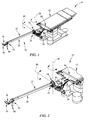
- FIG. 2 is an enlarged partial perspective view of the limb-support unit of FIG. 1 ;
- FIG. 3 is an exploded assembly view of the limb-support unit of FIG. 1 showing that the limb-support unit includes a two-axis leg holder and a support platform;
- FIG. 4 is an exploded assembly view of the two-axis leg holder of FIG. 3 ;
- FIG. 5 is an enlarged partial perspective view of the two-axis leg holder of FIGS. 1-4 showing a horizontal-lock actuator in an engaged position causing a horizontal-position lock to remain in the blocking position blocking movement of the two-axis leg holder about a horizontal axis relative to the support platform;
- FIG. 6 is a sectional view taken along line 6 - 6 of FIG. 5 showing the horizontal-position lock in the blocking position;
- FIG. 7 is a view similar to FIG. 5 showing the horizontal-lock actuator in an engaged position causing the horizontal-position lock to move to the unblocking position as suggested in FIG. 8 ;
- FIG. 8 is a sectional view taken along line 8 - 8 of FIG. 7 showing the horizontal-position lock moved to the unblocking position;
- FIG. 9 is a view similar to FIG. 5 showing a vertical-lock actuator in a disengaged position causing a vertical-position lock to remain in a locked position blocking movement of the two-axis leg holder about a vertical axis relative to the support platform;
- FIG. 10 is a sectional view taken along line 10 - 10 of FIG. 9 showing the vertical-position lock in the locked position;
- FIG. 11 is a view similar to FIG. 9 showing the vertical-position lock moved to the unlocked position allowing movement of the movable leg support relative to the support platform;
- FIG. 12 is a sectional view taken along line 12 - 12 of FIG. 11 showing the vertical-position lock moved to the unlocked position;
- FIG. 13 is an exploded assembly view of a limb-support unit showing that the limb-support unit includes another embodiment of a two-axis leg holder in accordance with the present disclosure
- FIG. 14 is an exploded assembly view of the two-axis leg holder of FIG. 13 ;
- FIG. 15 is an enlarged partial perspective view of the two-axis leg holder of FIGS. 13 and 14 showing a horizontal-lock actuator in a disengaged position causing a horizontal-position lock included in the two-axis leg holder to remain in the blocking position blocking movement of the two-axis leg holder about a horizontal axis relative to the support platform;
- FIG. 16 is a sectional view taken along line 16 - 16 of FIG. 15 showing the horizontal-position lock in the blocking position;
- FIG. 17 is a view similar to FIG. 15 showing the horizontal-lock actuator in an engaged position causing the horizontal-position lock to move to the unblocking position as suggested in FIG. 18 ;
- FIG. 18 is a sectional view taken along line 18 - 18 of FIG. 17 showing the horizontal-position lock moved to the unblocking position;
- FIG. 19 is a view similar to FIG. 15 showing a vertical-lock actuator in a disengaged position causing a vertical-position lock to remain in a locked position;
- FIG. 20 is a sectional view taken along line 20 - 20 of FIG. 19 showing the vertical-position lock in the locked position;
- FIG. 21 is a view similar to FIG. 19 showing the vertical-position lock moved to the unlocked position.
- FIG. 22 is a sectional view taken along line 22 - 22 of FIG. 21 showing the vertical-position lock moved to the unlocked position.
- a support apparatus 10 includes, for example, a surgical table 12 and a limb-support unit 14 as shown in FIGS. 1-3 .
- the limb-support unit 14 for example, is coupled to a foot end 16 of the surgical table 12 as shown in FIGS. 1 and 2 .
- the limb-support unit 14 supports a patient's legs (not shown) and the surgical table 12 supports a patient's upper body (not shown).
- the limb-support unit 14 may be used to place tension on the patient's legs during surgery. This is also called placing the patient's legs in traction.
- the patient's leg being operated on may need to be repositioned to provide the surgeon with improved access while maintaining the patient's leg in traction.
- the limb-support unit 14 in accordance with the present disclosure, provides the ability to reposition the patient's leg while maintaining that leg in traction.
- the limb-support unit 14 may be used to support a patient's arm (not shown) in tension as well.
- the limb-support unit 14 includes a support platform 18 , also called platform 18 , and a two-axis limb holder 22 , also called a two-axis leg holder 22 , as shown in FIGS. 1-3 .
- the support platform 18 is coupled to the foot end 16 of the surgical table 12 in a fixed position as shown in FIGS. 1 and 2 .
- the limb-support unit 14 may also include a one-axis leg holder that is coupled to the support platform 18 in a fixed position when supporting one of the patient's legs. When the one-axis leg holder is not supporting one of the patient's legs, the one-axis leg holder may be repositioned relative to the support platform 18 .
- the two-axis leg holder 22 is coupled to the support platform 18 as shown in FIGS. 1 and 2 . Portions of the two-axis leg holder 22 move relative to the support platform 18 as suggested in FIGS. 1 and 2 .
- the two-axis leg holder 22 includes a joint mount 24 , a multi-axis joint 26 , and a spar 28 as shown in FIGS. 3 and 4 .
- the joint mount 24 is coupled to the support platform 18 in a fixed position while the limb-support unit 14 supports portions of the patient. When the limb-support unit 14 is not supporting portions of the patient, the joint mount 24 may be decoupled from the support platform 18 and repositioned on the support platform 18 .
- the multi-axis joint 26 is arranged to interconnect the spar 28 and the joint mount 24 to cause the spar 28 to move relative to the joint mount 24 as suggested in FIG. 4 .
- the spar 28 is coupled to the multi-axis joint 26 and arranged to extend away from the multi-axis joint 26 to support the patient's leg in traction during surgery.
- the multi-axis joint 26 includes a joint housing 30 , a support platform 32 , a vertical-position lock 34 , and a horizontal-position lock 36 as shown in FIGS. 4-12 .
- the horizontal-position lock 36 lies between and interconnects the joint mount 24 and the support platform 32 .
- the joint housing 30 is coupled to the support platform 32 to move with the support platform 32 .
- the vertical-position lock 34 interconnects portions of the joint housing 30 and the spar 28 . Together, the vertical-position lock 34 and the horizontal-position lock 36 cooperate to control movement of the spar 28 relative to the joint mount 24 as suggested in FIGS. 1-3 .
- the horizontal-position lock 36 is movable between a blocking position shown in FIGS. 5 and 6 and an unblocking position shown in FIGS. 7 and 8 .
- the horizontal-position lock 36 when in the blocking position, blocks movement of the spar 28 , the vertical-position lock 34 , the joint housing 30 , and the support platform 32 relative to the joint mount 24 .
- the horizontal-position lock 36 is in the unblocking position, the spar 28 , the vertical-position lock 34 , the joint housing 30 , and the support platform 32 are freed to rotate together as a unit about a vertical axis 38 relative to the joint mount 24 .
- the vertical-position lock 34 is movable between a locked position shown in FIGS. 9 and 10 and an unlocked position shown in FIGS. 11 and 12 .
- the vertical-position lock 34 blocks movement of the spar 28 relative to portions of the joint housing 30 , the horizontal-position lock 36 , and the support platform 32 .
- the vertical-position lock 34 allows the spar 28 to move about a horizontal axis 40 .
- the vertical-position lock 34 may move between the locked and the unlocked positions when the horizontal-position lock 36 is in either the blocking or the unblocking positions.
- the horizontal-position lock 36 may move between the blocking and the unblocking position when the vertical-position lock 34 is in either the locked or the unlocked position.
- the horizontal-position lock 36 includes a stationary disk 42 , a set 44 of movable pins, and a movable disk 46 as shown in FIG. 4 .
- the set 44 of movable pins includes twenty pins spaced-apart radially from one another an equal amount.
- Stationary disk 42 is coupled to the support platform 32 in a fixed position relative to the support platform 32 .
- the set 44 of movable pins are trapped between the stationary disk 42 and the support platform 32 and spring biased to extend away from the support platform 32 .
- the set 44 of pins are configured to move through an associated set 47 of holes formed in the stationary disk between a retracted position and an extended position.
- the set 47 of holes includes twenty holes aligned with the set 44 of twenty pins.
- the movable disk 46 is coupled to the joint mount 24 to move relative to the joint mount 24 , the stationary disk 42 , and the set 44 of pins.
- the movable disk 46 When the horizontal-position lock 36 is in the blocking position, the movable disk 46 lies in confronting relation with the stationary disk 42 and four pins of the set 44 of pins extend through four holes of the set 47 of holes in the stationary disk 42 and extend into four holes formed in the movable disk 46 .
- the movable disk 46 is formed to include a set 48 of sixteen holes therein. The sixteen holes are spaced-apart radially from one another an equal amount.
- the movable disk 46 When the horizontal-position lock is in the unblocking position, the movable disk 46 is spaced apart from the stationary disk 42 a distance sufficient to cause the four pins to be withdrawn from the four holes formed in the movable disk 46 allowing the stationary disk 42 to rotate about the vertical axis 38 with the support platform 32 relative to the movable disk 46 .
- the stationary disk 42 includes twenty holes, there are twenty pins, and the movable disk 46 includes sixteen holes, only four holes in the stationary disk 42 , four pins, and four holes in the movable disk 46 align every about 4.5 degrees. As a result, the horizontal-position lock can be adjusted in about 4.5 degree increments. However, the number holes in the stationary disk 42 , the number of pin in set 44 , and the number of holes in movable disk 46 may be changed to suit the increment desired.
- the vertical-position lock 34 also called a hirth joint or hirth coupling, includes a stationary plate 50 and a movable plate 52 as shown in FIG. 4 .
- the stationary plate 50 is coupled to a second shell support 116 included in joint housing 30 to move with the second shell support 116 .
- the movable plate 52 is coupled to a housing shell 112 included in the joint housing 30 to move back and forth with the housing shell 112 along the horizontal axis 40 relative to the stationary plate 50 .
- the movable plate 52 lies in confronting engaging relation with stationary plate 50 as shown in FIG. 10 .
- the movable plate 52 When the vertical-position lock 34 is in the unlocked position, the movable plate 52 is spaced apart from the stationary plate 50 allowing the movable plate 52 to rotate up and down about horizontal axis 40 relative to shell supports 114 , 116 and stationary plate 50 .
- the stationary plate 50 includes a disk and a plurality of radially-extending inwardly-projecting teeth appended to the disk.
- the plurality of radially-extending inwardly-projecting teeth extend towards the movable plate 52 .
- the movable plate 52 includes a disk and a plurality of radially-extending outwardly-projecting teeth appended to the disk.
- the radially-extending outwardly-projecting teeth extend toward the stationary plate 50 .
- the teeth appended to both disk are numbered so as to compliment one another and are configured to mate with one another when the vertical-position lock 34 is in the locked position.
- the vertical-position lock 34 allows for adjustments in position of the spar 28 in about 4 degree increments.
- the design of the stationary plate 40 and the movable plate 52 may be varied to achieve the increment desired.
- Each of the vertical-position lock 34 and the horizontal-position lock 36 are movable independently of one another as suggested in FIGS. 1 and 2 .
- Vertical-position lock 34 is moved by a vertical-lock actuator 54 included in the two-axis leg holder 22 as shown in FIGS. 9-12 .
- the horizontal-position lock 36 is moved by the horizontal-lock actuator 56 included in the two-axis leg holder 22 as shown in FIGS. 5-8 .
- the vertical-lock actuator 54 is coupled to the spar 28 and to the vertical-position lock 34 and is movable to cause the vertical-position lock 34 to move between the locked and unlocked positions.
- the horizontal-lock actuator 56 is coupled to the spar 28 and to the horizontal-position lock 36 and is movable to cause the horizontal-position lock 36 to move between the blocking and the unblocking positions.
- the horizontal-lock actuator 56 includes a trigger 58 , a first trigger linkage 60 , a second trigger linkage 62 , a connecting linkage 64 , a lever 66 , and a drive linkage 68 as shown in FIGS. 4 and 5 - 8 .
- the trigger 58 is coupled to a spar handle 70 included in the spar 28 to move relative to the spar handle 70 in response to application of an actuation force F to the trigger 58 .
- the first trigger linkage 60 interconnects the trigger 58 and the second trigger linkage 62 as shown in FIGS. 5 and 7 .
- the second trigger linkage 62 interconnects the first trigger linkage 60 and the connecting linkage 64 which extends along a beam 72 included in the spar 28 .
- the connecting linkage 64 is coupled to the lever 66 to cause the lever to pivot about a lever axis 74 as shown in FIGS. 6 and 8 .
- the lever is configured to engage and move the drive linkage 68 which is coupled to the movable disk 46 included in the vertical-position lock 34 .
- a caregiver applies the actuation force F to the trigger 58 causing the trigger 58 to pivot in a counter-clockwise direction 76 about a first trigger axis 78 as suggested in FIG. 5 and shown in FIG. 7 .
- Movement of the trigger 58 causes the first trigger linkage 60 to move toward the beam 72 which causes the second trigger linkage 62 to rotate about a second trigger axis 80 in the counter-clockwise direction 76 .
- Movement of the second trigger linkage 62 causes the connecting linkage 64 to be driven toward the multi-axis joint 26 as suggested in FIGS. 5 and 6 and shown in FIGS. 7 and 8 .
- Movement of the connecting linkage 64 causes the lever 66 to be rotated about the lever axis 74 in a counter-clockwise direction 82 .
- Rotation of the lever 66 engages and moves the drive linkage 68 in a downward direction 84 as suggested in FIG. 6 and shown in FIG. 8 .
- the movable disk 46 is coupled to the drive linkage 68 to move therewith and moves downwardly out of engagement with the pins included in the set 44 of pins.
- the horizontal-position lock 36 is moved to the unlocked position freeing the vertical-position lock 34 , portions of the joint housing 30 , and the spar 28 to move about the vertical axis 38 relative to the joint mount 24 .
- the horizontal-lock actuator 56 further includes a horizontal-lock bias spring 86 which provides a bias force to urge the horizontal-position lock 36 to return to the blocking position when the actuation force F is removed.
- the horizontal-lock bias spring 86 is positioned to lie between the joint mount 24 and the drive linkage 68 as shown in FIGS. 4 , 6 , and 8 .
- the vertical-lock actuator 54 includes a grip 88 , a rotation collar 90 , a rotation linkage 92 , a cam 94 , a cam follower 96 , and a bias mechanism 98 as shown in FIG. 4 and suggested in FIGS. 9-12 .
- the grip 88 is coupled to the spar handle 70 to extend perpendicularly away from the spar handle 70 as shown in FIGS. 9 and 11 .
- the rotation collar 90 is coupled to the grip 88 to move therewith as the grip 88 is rotated about a rotation axis 100 in a counter-clockwise direction 110 as suggested in FIG. 9 and shown in FIG. 11 .
- the rotation axis 100 is defined by the rotation linkage 92 .
- the rotation collar 90 is also coupled to the spar handle 70 to rotate relative to the spar handle 70 .
- the rotation linkage 92 interconnects the rotation collar 90 and the cam 94 to cause movement of the rotation collar 90 to be translated to the cam 94 .
- the rotation linkage is arranged to extend between the multi-axis joint 26 and the spar handle 70 .
- the rotation linkage 92 is formed to include a hollow passageway therein and the connecting linkage 64 of the horizontal-lock actuator 56 is configured to extend there through for movement independent of the rotation linkage 92 .
- the cam follower 96 is coupled to the movable plate 52 and the housing shell 112 to cause the movable plate 52 , the cam follower 96 , and the housing shell 112 to move back and forth along the horizontal axis 40 in response to movement of the cam 94 .
- the bias mechanism 98 is positioned to lie between a portion of the cam follower 96 and a first shell support 114 included in joint housing 30 to cause the cam follower 96 and the movable plate 52 to move away from the stationary plate 50 as shown in FIGS. 9 and 11 .
- the bias mechanism 98 provides another bias force to urge the vertical-position lock 34 to the unlocked position when the rotation force R is removed from the grip 88 .
- the spar 28 is capable of moving about the horizontal axis 40 through a range of motion of about 20 degrees down from a generally horizontal position and about 55 degrees up from a generally horizontal position.
- the two-axis leg holder 22 is also configured to support a portion of a 350 pound patient with an inseam of about 42 inches. As a result, the two-axis leg holder 22 can withstand a torque of about 250 foot pounds when the spar 28 is generally horizontal.
- the grip 88 of vertical-lock actuator 54 includes a rod 104 , a grip shell 106 , and a shell bias spring 108 as shown in FIG. 4 .
- the rod 104 is coupled to the rotation collar 90 to move therewith.
- the grip shell 106 is coupled to the rod 104 to move back and forth relative to the rod 104 between a first position and a second position.
- the shell bias spring 108 is coupled to the rod and the grip shell 106 to bias the grip shell 106 into the first position.
- an upper tapered portion of the grip shell 106 is arranged to mate with an associated tapered portion formed in the beam 72 . The two tapered portions cooperate to maintain grip shell 106 in the first position.
- the grip shell 106 When the grip shell 106 is in the second position, the grip shell 106 is spaced apart from the beam 72 such that the two tapered portions are no longer engaged with one another. As a result, grip 88 is freed to rotate about the rotation axis 100 when in the second position.
- the joint housing 30 includes a housing shell 112 , a first shell support 114 , a second shell support 116 , and a shell coupler 118 .
- the housing shell 112 is positioned to lie between and interconnect the first and the second shell supports 114 , 116 .
- the housing shell 112 is coupled to the support platform 32 to extend upwardly away from the support platform 32 .
- the first and second shell supports 114 , 116 are coupled to the support platform 32 and configured to receive portions of the cam follower 96 therein and provide rotative bearing engagement between the cam follower 96 and the shell supports 114 , 116 .
- the shell coupler 118 is coupled to both the shell supports 114 , 116 and is configured to maintain the shell supports 114 , 116 in spaced-apart relation to one another trapping the housing shell 112 therebetween.
- the shell coupler 118 is a nut and a bolt.
- a limb-support unit 214 includes the support platform 18 and a two-axis leg holder 222 as shown in FIG. 13 .
- the two-axis leg holder 222 includes the joint mount 24 , a multi-axis joint 226 , and a spar 28 as shown in FIGS. 13 and 14 .
- the multi-axis joint 226 is arranged to interconnect the spar 28 and the joint mount 24 to cause the spar 28 to move relative to the joint mount 24 as suggested in FIG. 4 .
- the spar 28 is coupled to the multi-axis joint 226 and arranged to extend away from the multi-axis joint 226 to support the patient's leg in traction during surgery.
- the multi-axis joint 226 includes the joint housing 30 , the support platform 32 , a vertical-position lock 234 , and the horizontal-position lock 36 as shown in FIGS. 14-22 .
- the horizontal-position lock 36 lies between and interconnects the joint mount 24 and the support platform 32 .
- the joint housing 30 is coupled to the support platform 32 to move with the support platform 32 .
- the vertical-position lock 234 interconnects the joint housing 30 and the spar 28 . Together, the vertical-position lock 234 and the horizontal-position lock 36 cooperate to control movement of the spar 28 relative to the joint mount 24 as suggested in FIG. 13 .
- the horizontal-position lock 36 is movable between a blocking position shown in FIGS. 15 and 16 and an unblocking position shown in FIGS. 17 and 18 .
- the horizontal-position lock 36 when in the blocking position, blocks movement of the spar 28 , the vertical-position lock 234 , the joint housing 30 , and the support platform 32 relative to the joint mount 24 .
- the horizontal-position lock 36 is in the unblocking position, the spar 28 , the vertical-position lock 234 , the joint housing 30 , and the support platform are freed to rotate together as a unit about the vertical axis 38 relative to the joint mount 24 .
- the vertical-position lock 234 is movable between a locked position shown in FIGS. 19 and 20 and an unlocked position shown in FIGS. 21 and 22 .
- the vertical-position lock 234 blocks movement of the spar 28 relative to the joint housing 30 , the horizontal-position lock 36 , and the support platform 32 .
- the vertical-position lock 234 allows the spar 28 to move about the horizontal axis 40 .
- the vertical-position lock 234 may move between the locked and the unlocked positions when the horizontal-position lock 36 is in either the blocking or the unblocking positions.
- the horizontal-position lock 36 may move between the blocking and the unblocking position when the vertical-position lock 234 is in either the locked or the unlocked position.
- the vertical-position lock 234 includes a vertical stationary disk 242 , a set 244 of movable pins, and a vertical movable disk 246 as shown in FIG. 14 .
- the set 244 of movable pins includes twenty pins spaced-apart radially from one another an equal amount.
- Vertical stationary disk 242 is coupled to the joint housing 30 in a fixed position relative to the joint housing 30 .
- the set 244 of movable pins are trapped between the vertical stationary disk 242 and the joint housing 30 .
- the set 244 of pins are configured to move through an associated set 247 of holes formed in the vertical stationary disk 242 between a retracted position and an extended position.
- the set 247 of holes includes twenty holes aligned with the set 244 of twenty pins.
- the vertical movable disk 246 is coupled to the joint housing 30 to move relative to the joint housing 30 , the vertical stationary disk 242 , and the set 244 of pins.
- the vertical movable disk 246 When the vertical-position lock 234 is in the locked position, the vertical movable disk 246 lies in confronting relation with the vertical stationary disk 242 and four pins of the set 244 of pins extend through four holes of the set of holes in the vertical stationary disk 242 and extend into four holes formed in the vertical movable disk 246 .
- the vertical movable disk 246 is formed to include a set 248 of holes therein.
- the set 248 of holes includes sixteen holes spaced-apart radially from one another an equal amount.
- the vertical movable disk 246 When the vertical-position lock 234 is in the unlocked position, the vertical movable disk 246 is spaced apart from the vertical stationary disk 242 to cause the four pins to be withdrawn from the four holes formed in the vertical movable disk 246 allowing the vertical stationary disk 242 to rotate about the horizontal axis 40 with the spar 28 .
- the vertical stationary disk 242 includes twenty holes, there are twenty pins, and the vertical movable disk 246 includes sixteen holes, only four holes in the vertical stationary disk 242 , four pins, and four holes in the vertical movable disk 246 align every 4.5 degrees. As a result, the vertical-position lock 234 can be adjusted in 4.5 degree increments. However, the number holes in the vertical stationary disk 242 , the number of pins in the set 244 , and the number of holes in the vertical movable disk 246 may be changed to suit the increment desired.
- Each of the vertical-position lock 234 and the horizontal-position lock 36 are movable independently of one another.
- the vertical-position lock 234 is moved by a vertical-lock actuator 254 included in two-axis leg holder 222 as shown in FIGS. 19-22 .
- the vertical-lock actuator 254 is coupled to the spar 28 and to the vertical-position lock 234 and is movable to cause the vertical-position lock 234 to move between the locked and unlocked positions.
- the vertical-lock actuator 254 includes a rotation collar 290 , a rotation linkage 292 , a cam 294 , and a cam follower 296 as shown in FIG. 14 and suggested in FIGS. 19-22 .
- the rotation collar 290 is coupled to the spar handle 70 to move therewith as the spar handle 70 is rotated about the rotation axis 100 in a clockwise direction 2110 as suggested in FIG. 19 and shown in FIG. 21 .
- the rotation axis 100 is defined by the rotation linkage 292 .
- the rotation linkage 292 interconnects the rotation collar 290 and the cam 294 to cause movement of the rotation collar 290 to be translated to the cam 294 .
- the rotation linkage 292 is arranged to extend between the multi-axis joint 226 and the spar handle 270 .
- the rotation linkage 292 is formed to include a hollow passageway therein and the connecting linkage 64 of the horizontal-lock actuator 56 is configured to extend there through for movement independent of the rotation linkage 292 .
- the cam follower 296 is coupled to the vertical movable disk 246 to cause the vertical movable disk 246 and the cam follower 296 to move back and forth along the horizontal axis 40 in response to movement of the cam 294 .
- Bias may be provided to the vertical-lock actuator 254 by gravity or inclusion of a bias mechanism. Bias may cause the cam follower 296 and the vertical movable disk 246 to move away from the vertical stationary disk 242 as shown in FIGS. 19 and 21 .
- the vertical-lock actuator 254 may further include a vertical-lock bias spring which provides another bias force to urge the vertical-position lock 234 to return to the locked position when the rotation force R is removed from the spar handle 70 .
- the vertical-lock bias spring may be positioned to lie between the joint housing 30 and the cam follower to bias the vertical-position lock 234 to the locked position.
Abstract
Description
Claims (32)
Priority Applications (4)
| Application Number | Priority Date | Filing Date | Title |
|---|---|---|---|
| US13/790,148 US9161875B2 (en) | 2012-09-07 | 2013-03-08 | Multi-axis joint for a spar of a limb holder |
| EP13183032.5A EP2705820B1 (en) | 2012-09-07 | 2013-09-04 | Multi-axis joint for a spar of a limb holder |
| US14/869,339 US10238568B2 (en) | 2012-09-07 | 2015-09-29 | Release handle mechanisms for a spar of a limb holder |
| US14/986,136 US10398615B2 (en) | 2012-09-07 | 2015-12-31 | Multi-axis joint for a spar of a limb holder |
Applications Claiming Priority (2)
| Application Number | Priority Date | Filing Date | Title |
|---|---|---|---|
| US201261698157P | 2012-09-07 | 2012-09-07 | |
| US13/790,148 US9161875B2 (en) | 2012-09-07 | 2013-03-08 | Multi-axis joint for a spar of a limb holder |
Related Child Applications (1)
| Application Number | Title | Priority Date | Filing Date |
|---|---|---|---|
| US14/869,339 Continuation US10238568B2 (en) | 2012-09-07 | 2015-09-29 | Release handle mechanisms for a spar of a limb holder |
Publications (2)
| Publication Number | Publication Date |
|---|---|
| US20140068863A1 US20140068863A1 (en) | 2014-03-13 |
| US9161875B2 true US9161875B2 (en) | 2015-10-20 |
Family
ID=49170550
Family Applications (3)
| Application Number | Title | Priority Date | Filing Date |
|---|---|---|---|
| US13/790,148 Active US9161875B2 (en) | 2012-09-07 | 2013-03-08 | Multi-axis joint for a spar of a limb holder |
| US14/869,339 Active 2034-03-08 US10238568B2 (en) | 2012-09-07 | 2015-09-29 | Release handle mechanisms for a spar of a limb holder |
| US14/986,136 Active 2034-11-08 US10398615B2 (en) | 2012-09-07 | 2015-12-31 | Multi-axis joint for a spar of a limb holder |
Family Applications After (2)
| Application Number | Title | Priority Date | Filing Date |
|---|---|---|---|
| US14/869,339 Active 2034-03-08 US10238568B2 (en) | 2012-09-07 | 2015-09-29 | Release handle mechanisms for a spar of a limb holder |
| US14/986,136 Active 2034-11-08 US10398615B2 (en) | 2012-09-07 | 2015-12-31 | Multi-axis joint for a spar of a limb holder |
Country Status (2)
| Country | Link |
|---|---|
| US (3) | US9161875B2 (en) |
| EP (1) | EP2705820B1 (en) |
Cited By (12)
| Publication number | Priority date | Publication date | Assignee | Title |
|---|---|---|---|---|
| US20160106612A1 (en) * | 2012-09-07 | 2016-04-21 | Allen Medical Systems, Inc. | Multi-axis joint for a spar of a limb holder |
| USD792595S1 (en) * | 2016-01-25 | 2017-07-18 | Dongguan Weihong Hardware And Plastic Products Co., Ltd. | Automatic support for headrest |
| US10238569B2 (en) * | 2013-10-18 | 2019-03-26 | MAQUET GmbH | Fastening unit for fastening a device for supporting a patient to be x-rayed to an operating table |
| USD878836S1 (en) | 2017-08-17 | 2020-03-24 | Stryker Corp. | Table extender |
| US10828218B2 (en) | 2015-06-05 | 2020-11-10 | Stryker Corporation | Surgical table and accessories to facilitate hip arthroscopy |
| US10835440B2 (en) * | 2016-04-01 | 2020-11-17 | Allen Medical Systems, Inc. | Boot carriage for repositioning a surgical boot along a support rod |
| US11234885B2 (en) * | 2018-02-20 | 2022-02-01 | Allen Medical Systems, Inc. | Adjustable lithotomy positioning apparatus with a limb rest |
| US20220338633A1 (en) * | 2019-10-08 | 2022-10-27 | Entellus Medical, Inc. | Headrest for a Procedure Chair and Procedure Chair Having a Headrest |
| US11510805B2 (en) | 2017-02-06 | 2022-11-29 | Stryker Corp. | Anatomical gripping system for gripping the leg and foot of a patient when effecting hip distraction and/or when effecting leg positioning |
| US11559455B2 (en) | 2017-02-06 | 2023-01-24 | Stryker Corp. | Distraction frame for effecting hip distraction |
| US11564855B2 (en) | 2020-09-28 | 2023-01-31 | Stryker Corporation | Systems and methods for supporting and stabilizing a patient during hip distraction |
| US11684532B2 (en) | 2017-02-06 | 2023-06-27 | Stryker Corp. | Method and apparatus for supporting and stabilizing a patient during hip distraction |
Families Citing this family (5)
| Publication number | Priority date | Publication date | Assignee | Title |
|---|---|---|---|---|
| EP2873405B1 (en) * | 2013-11-18 | 2016-05-18 | Schaerer Medical Management AG | Modular operating table |
| US20150196447A1 (en) * | 2014-01-13 | 2015-07-16 | Athello, Inc. | Lower Extremity Positioning Assembly And Table Extension |
| US20160346147A1 (en) * | 2015-05-31 | 2016-12-01 | Christopher James Brown | Surgical limb positioning and support device and method |
| DE102017110718A1 (en) * | 2017-05-17 | 2018-11-22 | MAQUET GmbH | Medical support arm with lockable swivel joint |
| BE1026472B1 (en) * | 2018-07-16 | 2020-02-10 | Orfit Ind | First trunk element of a connecting assembly for releasably connecting an extension panel to a patient support panel mounted on a pedestal |
Citations (151)
| Publication number | Priority date | Publication date | Assignee | Title |
|---|---|---|---|---|
| US870324A (en) | 1907-02-06 | 1907-11-05 | David Frank | Operating-table. |
| US2188592A (en) | 1936-12-21 | 1940-01-30 | Damon R Hosken | Invalid bed |
| US2509086A (en) | 1948-08-10 | 1950-05-23 | Eaton Appliance Corp | Headrest for operating tables |
| US2872259A (en) | 1956-11-26 | 1959-02-03 | Allen & Hanburys Ltd | Operation tables having removably supported interchangeable head and leg extension sections |
| US2935286A (en) | 1956-01-27 | 1960-05-03 | Parsons Jim Skelt | Infusion standard |
| US3015113A (en) | 1955-12-02 | 1962-01-02 | Superior Sleeprite Corp | Adjustable bed |
| US3042025A (en) | 1955-03-01 | 1962-07-03 | Robert P Jackson | Apparatus for treating body and spinal distortions |
| US3046072A (en) | 1960-01-21 | 1962-07-24 | Shampaine Ind Inc | Accessory supports for surgical operating tables and the like |
| US3099441A (en) | 1959-12-29 | 1963-07-30 | Ries Mfg Company | Surgical device |
| US3188079A (en) | 1962-04-05 | 1965-06-08 | American Sterilizer Co | Surgical headrest |
| US3828377A (en) | 1973-02-02 | 1974-08-13 | G Fary | Adjustable body rest |
| US3873081A (en) | 1974-01-07 | 1975-03-25 | Robert H Smith | Surgical support |
| US3946452A (en) | 1975-03-17 | 1976-03-30 | Eary Sr George D | Adjustable head and shoulder rest |
| US3947686A (en) | 1974-04-25 | 1976-03-30 | The Babcock & Wilcox Co. | Graphite composite X-ray transparent patient support |
| US4018412A (en) | 1975-10-14 | 1977-04-19 | Kees Surgical Specialty Company | Bracket for an operating table |
| US4028754A (en) | 1975-03-17 | 1977-06-14 | Eary Sr George Daniel | Adjustable head and shoulder rest |
| US4033339A (en) | 1975-08-12 | 1977-07-05 | by said Gratz L. Roberts SAID William P Roberts | Cervical side posture table having effective head restraint means |
| US4054282A (en) | 1976-11-19 | 1977-10-18 | Louis O. Scheu, Jr. | Auxiliary operating table for hand surgery and the like |
| US4108426A (en) | 1978-01-26 | 1978-08-22 | Siemens Aktiengesellschaft | Device for holding the head of a patient |
| US4139917A (en) | 1977-10-17 | 1979-02-20 | Loel Fenwick | Labor, delivery and patient care bed |
| US4143652A (en) | 1976-01-29 | 1979-03-13 | Hans Meier | Surgical retaining device |
| US4225125A (en) | 1977-04-28 | 1980-09-30 | Matburn (Holdings) Limited | Operation table |
| US4239200A (en) | 1979-02-05 | 1980-12-16 | Sarrafian Shahan K | Foot-ankle surgical table |
| US4346488A (en) | 1979-08-13 | 1982-08-31 | Eary Sr George D | Adjustable upper body rest |
| US4355631A (en) | 1981-03-19 | 1982-10-26 | Minnesota Scientific, Inc. | Surgical retractor apparatus with improved clamping device |
| US4383351A (en) | 1981-10-23 | 1983-05-17 | Loel Fenwick | Universal clamp |
| US4391438A (en) | 1981-06-12 | 1983-07-05 | Heffington Jr Charles A | Patient support attachment for surgical tables |
| US4398707A (en) | 1981-09-16 | 1983-08-16 | Cloward Ralph B | Surgical saddle |
| USD271834S (en) | 1980-10-07 | 1983-12-20 | Huntsinger Daniel F | Cushion |
| US4455698A (en) | 1981-10-21 | 1984-06-26 | Eary Sr George D | Adjustable upper body rest |
| US4474364A (en) | 1982-11-29 | 1984-10-02 | American Sterilizer Company | Surgical table |
| US4487523A (en) | 1981-12-31 | 1984-12-11 | American Sterilizer Company | Accessory clamp for abductor bar |
| US4506872A (en) | 1982-09-29 | 1985-03-26 | Siemens Aktiengesellschaft | Device for mounting accessories on a patient support apparatus |
| US4520800A (en) | 1983-05-09 | 1985-06-04 | Standex International Corporation | Patient treatment table |
| US4526355A (en) | 1982-09-29 | 1985-07-02 | Moore Robert R | Arthroscopic leg holder |
| US4527555A (en) | 1981-05-18 | 1985-07-09 | Hermann Ruf | Auxiliary table for extension and repositioning in medical operations |
| US4527787A (en) | 1983-05-31 | 1985-07-09 | Collis Jr John S | X-ray table |
| US4531247A (en) | 1982-09-28 | 1985-07-30 | Eary Sr George D | Adjustable upper body rest |
| US4549501A (en) | 1984-05-17 | 1985-10-29 | Iowa State University Research Foundation, Inc. | Animal head restrainer |
| US4558857A (en) | 1982-02-19 | 1985-12-17 | Contraves Ag | Operating table |
| US4559930A (en) | 1984-05-07 | 1985-12-24 | Cobiski John F | Thoracic bench |
| US4562588A (en) | 1981-11-20 | 1985-12-31 | Hermann Ruf | Positioning device for an extension and repositioning apparatus |
| US4583725A (en) | 1985-03-05 | 1986-04-22 | Arnold Roger D | Patient support frame for posterior lumbar laminectomy |
| US4616813A (en) | 1984-04-10 | 1986-10-14 | Mcconnell Bernard E | Suspension for surgical support apparatus |
| US4635914A (en) | 1984-01-03 | 1987-01-13 | Kabanek Joseph R | Orthopedic attachment for surgical tables |
| US4653482A (en) | 1985-05-17 | 1987-03-31 | Kurland Kenneth Z | Upper-extremity traction tray attachment for operating tables |
| US4662619A (en) | 1985-02-26 | 1987-05-05 | Charles D. Ray, Ltd. | Kneeling attachment for operations in the prone sitting position |
| US4671728A (en) | 1985-07-11 | 1987-06-09 | Applied Power, Inc. | Hydraulic system for a mobile transport vehicle that supports and positions a load relative to a docking structure |
| US4712781A (en) | 1986-05-12 | 1987-12-15 | Watanabe Orthopedic Systems, Inc. | Operating table for microscopic lumbar laminectomy surgery |
| US4729535A (en) | 1986-12-09 | 1988-03-08 | Frazier Stanley J | Apparatus for supporting a cooking device |
| US4752064A (en) | 1987-03-23 | 1988-06-21 | Gene Voss | Therapeutic head support |
| US4796846A (en) | 1987-06-01 | 1989-01-10 | Automated Medical Products, Corporation | Retaining device for a surgical instrument |
| US4827541A (en) | 1987-12-15 | 1989-05-09 | Vollman Kathleen M | Prone patient positioner |
| US4840363A (en) | 1981-05-27 | 1989-06-20 | Mcconnell Bernard E | Telescoping, sterile upright support assembly |
| US4852840A (en) | 1988-09-06 | 1989-08-01 | Marks Dale H | Clamp for mounting a device to a tubular |
| US4866796A (en) | 1985-04-17 | 1989-09-19 | Thomas J. Ring | Therapeutic table |
| US4872656A (en) | 1981-12-21 | 1989-10-10 | American Sterilizer Company | Orthopedic table with movable upper body and sacrum supports |
| US4901963A (en) | 1985-06-20 | 1990-02-20 | Universal Consolidated Methods, Inc. | Adjustable clamp |
| US4901964A (en) | 1985-01-22 | 1990-02-20 | Mcconnell Bernard E | Rail clamp |
| US4908892A (en) | 1988-11-07 | 1990-03-20 | Michelson Gary K | Spinal surgery chest bolster |
| US4971037A (en) | 1988-09-19 | 1990-11-20 | Pilling Co. | Surgical retractor support |
| US4989848A (en) | 1981-12-21 | 1991-02-05 | American Sterilizer Company | Apparatus for adjusting the position of the upper body support of an orthopedic table |
| US4995067A (en) | 1989-10-05 | 1991-02-19 | The United States Of America As Represented By The Secretary Of The Air Force | Surgical and x-ray operation table extension |
| US5009407A (en) | 1989-05-15 | 1991-04-23 | Watanabe Robert S | Surgical table for microscopic lumbar laminectomy surgery |
| US5088706A (en) | 1990-08-30 | 1992-02-18 | Jackson Roger P | Spinal surgery table |
| US5108213A (en) | 1991-03-22 | 1992-04-28 | Edgewater Medical Equipment Systems, Inc. | Clamping assembly |
| US5121892A (en) | 1991-02-15 | 1992-06-16 | Herzog Kenneth J | Pivoting rail clamp |
| US5131106A (en) | 1990-08-30 | 1992-07-21 | Jackson Roger P | Spinal surgery table |
| US5135210A (en) | 1989-05-01 | 1992-08-04 | Michelson Gary K | Surgical armboard attachment device |
| US5163193A (en) | 1991-10-11 | 1992-11-17 | Whitmore Henry B | 4-post spinal system with vacuum lock |
| US5197975A (en) | 1989-01-09 | 1993-03-30 | Bruno Mombrinie | Radiolucent spine support frame |
| US5239716A (en) | 1992-04-03 | 1993-08-31 | Fisk Albert W | Surgical spinal positioning frame |
| US5276927A (en) | 1992-09-21 | 1994-01-11 | Ohio Medical Instrument Co. | Radiolucent head support |
| US5279310A (en) | 1993-01-26 | 1994-01-18 | Ching Chi Hsien | Spinal column correction device |
| US5287575A (en) | 1992-11-09 | 1994-02-22 | Allen Medical Systems | Hand table |
| US5297539A (en) | 1990-08-31 | 1994-03-29 | Liebl Thomas J | Therapeutic device for chiropractic diagnosis and treatment |
| US5297303A (en) | 1993-04-26 | 1994-03-29 | Stafford Teresa E | Examination table top |
| US5320444A (en) | 1993-01-22 | 1994-06-14 | Bookwalter John R | Enclosed surgical apparatus clamp |
| US5400772A (en) | 1991-05-24 | 1995-03-28 | Minnesota Scientific, Inc. | Surgical retractor apparatus with improved clamping device |
| US5444882A (en) | 1990-09-17 | 1995-08-29 | Orthopedic Systems, Inc. | Spinal surgery table |
| US5452728A (en) | 1989-03-02 | 1995-09-26 | Superspine, Inc. | Soft tissue support system |
| US5489258A (en) | 1993-05-14 | 1996-02-06 | Bissell Inc. | Multi-position body support |
| US5520623A (en) | 1995-03-07 | 1996-05-28 | Williams; Dallas | Head and face support device |
| US5535466A (en) | 1992-09-24 | 1996-07-16 | Snell; Thomas B. | Surgical tables |
| US5538215A (en) | 1994-11-15 | 1996-07-23 | Midmark Corporation | Siderail socket |
| US5566682A (en) | 1995-08-11 | 1996-10-22 | Yavitz; Edward Q. | Therapeutic support device |
| US5575027A (en) | 1995-04-18 | 1996-11-19 | Mueller; George B. | Method of supporting a chest and abdomen and apparatus therefor |
| US5613254A (en) | 1994-12-02 | 1997-03-25 | Clayman; Ralph V. | Radiolucent table for supporting patients during medical procedures |
| US5628078A (en) | 1994-08-15 | 1997-05-13 | Midmark Corporation | Surgical table side extender assembly |
| US5642302A (en) | 1995-02-21 | 1997-06-24 | Banque De Developpement Du Canada | Method and apparatus for positioning a human body |
| US5655238A (en) | 1996-04-05 | 1997-08-12 | Midmark Corporation | Extreme position surgery table top attachment |
| US5658315A (en) | 1994-02-23 | 1997-08-19 | Orthopedic Systems, Inc. | Apparatus and method for lower limb traction |
| US5675851A (en) | 1996-10-08 | 1997-10-14 | Feathers; John A. | X-ray table extension for head and upper body support |
| US5680861A (en) | 1996-07-08 | 1997-10-28 | General Electric Company | Modular subject positioning system for medical imaging |
| US5701991A (en) | 1996-02-06 | 1997-12-30 | Hi-Speed Checkweigher Co., Inc. | Clamping mechanism |
| US5741210A (en) | 1995-10-10 | 1998-04-21 | Minnesota Scientific, Inc. | Clamping device for a surgical retractor |
| US5758647A (en) | 1996-10-17 | 1998-06-02 | Cummins; Jimmie E. | Support and indexing apparatus for lumbar region imaging |
| US5758374A (en) | 1996-05-20 | 1998-06-02 | Ronci; Samuel | Portable table assembly |
| US5836559A (en) | 1997-05-23 | 1998-11-17 | Ronci; Samuel | Clamp for securing a pole to a stationary object |
| US5836026A (en) | 1997-05-22 | 1998-11-17 | Reed; Michael C. | Orthopedic trapeze with self-locking rotatable mechanism |
| US5926876A (en) | 1996-11-19 | 1999-07-27 | Compacta International, Ltd. | Surgical operating table accessory for shoulder procedures |
| USD414974S (en) | 1998-07-18 | 1999-10-12 | JEM International Corporation | Face down cushion |
| US6001076A (en) | 1995-06-20 | 1999-12-14 | Nuffield Nursing Homes Trust | Apparatus for positioning a patient for spinal surgery |
| US6003174A (en) | 1997-09-03 | 1999-12-21 | Kantrowitz; Allen | Radiolucent table extension and method |
| US6065165A (en) | 1997-08-22 | 2000-05-23 | Hill-Rom, Inc. | Prone patient apparatus |
| US6076525A (en) | 1999-01-28 | 2000-06-20 | Hoffman; Michael D. | Frame for prone surgical positioning |
| US6154903A (en) | 1997-11-07 | 2000-12-05 | Wai-Chung; Patrick | Body rest structures |
| US6154901A (en) | 1997-09-26 | 2000-12-05 | New York Society For The Relief Of The Ruptured And Crippled Maintaining The Hospital For Special Surgery | Spinal-surgery table |
| US6195820B1 (en) | 1999-05-27 | 2001-03-06 | Hill-Rom, Inc. | Pivoting hand table |
| US6199552B1 (en) | 1999-04-07 | 2001-03-13 | Pedro R. Crespo | Bed with suspended platform |
| US6199233B1 (en) | 1998-04-24 | 2001-03-13 | Allen Kantrowitz | Radiolucent table extension assembly |
| US6237172B1 (en) | 1998-10-01 | 2001-05-29 | Morgan Medesign, Inc. | Patient support table |
| US6260220B1 (en) | 1997-02-13 | 2001-07-17 | Orthopedic Systems, Inc. | Surgical table for lateral procedures |
| US6295671B1 (en) | 1998-03-06 | 2001-10-02 | Ohio Medical Instrument Company, Inc. | Medical surgical table including interchangeable orthopedic attachment and scanning table |
| US6324710B1 (en) | 2000-04-14 | 2001-12-04 | Arthur S. Hernandez | Prone support apparatus for spinal procedures |
| US20020032927A1 (en) | 1999-02-11 | 2002-03-21 | Dinkler Charles E. | Hinged adaptor assembly for radiolucent table extension |
| US6382576B1 (en) | 1999-06-08 | 2002-05-07 | Hill-Rom Services, Inc. | Clamping apparatus |
| US6385802B1 (en) | 1999-12-17 | 2002-05-14 | Bamcor, Inc. | Operating room table having lumbar support bar |
| US20020061255A1 (en) | 1999-03-04 | 2002-05-23 | Nguyen Khoi Minh | Fluid delivery mechanism |
| US20020061225A1 (en) | 2000-03-28 | 2002-05-23 | Boucher Michael M. | Socket and rail clamp apparatus |
| US6428497B1 (en) | 2001-09-01 | 2002-08-06 | Richard A. Crouch | Therapeutic table system |
| US20020170115A1 (en) | 1997-11-07 | 2002-11-21 | Borders Richard L. | Leg section support for a surgical table |
| US20030028967A1 (en) * | 2001-08-13 | 2003-02-13 | Peter Schuerch | Adjustable position limb support for surgical tables |
| US6526609B2 (en) | 2001-03-29 | 2003-03-04 | William Beaumont Hospital | X-ray transparent hospital bed compatible with open geometry portable CT scanners |
| US20030061660A1 (en) | 2000-10-30 | 2003-04-03 | American Table Manufacturing, Inc. | Surgical table top and accessory clamp used thereon |
| US6584630B1 (en) | 2000-04-06 | 2003-07-01 | Ohio Medical Instrument Company, Inc. | Radiolucent surgical table extension assembly and method |
| US20030167569A1 (en) | 2002-03-11 | 2003-09-11 | Newkirk David C. | Surgical table having integral lateral supports |
| US6622324B2 (en) | 2000-03-28 | 2003-09-23 | Hill-Rom Services, Inc. | Hip brace apparatus |
| US6663055B2 (en) | 2000-03-15 | 2003-12-16 | The Or Group, Inc. | Armboard assembly |
| US6691350B2 (en) | 1999-12-13 | 2004-02-17 | Hill-Rom Services, Inc. | Accessories for a patient support apparatus |
| US6701553B1 (en) | 1999-04-21 | 2004-03-09 | Hill-Rom Services, Inc. | Proning bed |
| US6718581B2 (en) | 2001-06-06 | 2004-04-13 | Oakworks, Inc. | Support device |
| US20040133979A1 (en) * | 2003-01-13 | 2004-07-15 | Newkirk David C. | Orthopedic table apparatus |
| US20040133983A1 (en) | 2003-01-13 | 2004-07-15 | Newkirk David C. | Surgical table |
| US6813788B2 (en) | 2000-04-06 | 2004-11-09 | Schaerer Mayfield Usa, Inc. | Variable length radiolucent surgical table extension |
| WO2005020819A1 (en) | 2003-08-28 | 2005-03-10 | Oncolog Medical Qa Ab | Patient repositioning device and method |
| US20050160533A1 (en) | 2004-01-23 | 2005-07-28 | Hillenbrand Industries | Surgical positioning apparatus |
| US20050268400A1 (en) * | 2004-06-08 | 2005-12-08 | Francesco Siccardi | Converter system to couple and command a support of a patient to be operated |
| US7017211B2 (en) | 2001-03-29 | 2006-03-28 | Kci Licensing, Inc. | Head restraint for therapeutic bed |
| US7020917B1 (en) | 2001-03-12 | 2006-04-04 | Steris Corporation | Radiolucent surgical table with low shadow accessory interface profile |
| US20060253985A1 (en) | 2004-11-10 | 2006-11-16 | Skripps Thomas K | Head support apparatus for spinal surgery |
| US20070074347A1 (en) | 2005-09-24 | 2007-04-05 | Qfix Systems, Llc | Radiation therapy patient couch top compatible with diagnostic imaging |
| US20080078031A1 (en) | 2006-10-02 | 2008-04-03 | Weinstein Samantha A | Modular System for Patient Positioning During Medical Procedures |
| WO2009029524A1 (en) | 2007-08-24 | 2009-03-05 | Allen Medical Systems, Inc. | Surgical table accessory platform |
| US7520007B2 (en) | 2004-11-10 | 2009-04-21 | Allen Medical Systems, Inc. | Accessory rail clamp with latch and lock mechanisms |
| US7520008B2 (en) | 2004-11-10 | 2009-04-21 | Allen Medical Systems | Surgical table extension |
| US7600281B2 (en) | 2004-11-10 | 2009-10-13 | Allen Medical Systems, Inc. | Body support apparatus for spinal surgery |
| US7669262B2 (en) | 2004-11-10 | 2010-03-02 | Allen Medical Systems, Inc. | Accessory frame for spinal surgery |
| US20130081635A1 (en) | 2011-09-30 | 2013-04-04 | Jesse Scott Drake | Surgical Assembly |
| US8683631B2 (en) * | 2012-01-26 | 2014-04-01 | American Sterilizer Company | Sacral pad for a medical table |
| US20140215718A1 (en) * | 2011-09-06 | 2014-08-07 | Malcolm Wootton | Operating tables and accessories |
Family Cites Families (7)
| Publication number | Priority date | Publication date | Assignee | Title |
|---|---|---|---|---|
| US4407045A (en) * | 1981-12-21 | 1983-10-04 | Boothe Leland H | Ladder hinge and multi-position locking mechanism therefor |
| US5645079A (en) * | 1994-12-02 | 1997-07-08 | Zahiri; Hormoz | Apparatus for mechanically holding, maneuvering and maintaining a body part of a patient during orthopedic surgery |
| EP1286640B1 (en) * | 2000-06-02 | 2009-08-05 | Hill-Rom Services, Inc. | Foot support for a patient support |
| US7243654B2 (en) * | 2005-04-08 | 2007-07-17 | Peter Schuerch | Adjustable position limb support for surgical tables |
| US7947006B2 (en) * | 2005-11-30 | 2011-05-24 | Smith & Nephew, Inc. | Hip distraction |
| WO2009062545A1 (en) * | 2007-11-13 | 2009-05-22 | Schaerer Mayfield Medical Ag | Modular device for positioning and immobilisation of a patient's body for surgical operations and corresponding operating table |
| US9161875B2 (en) | 2012-09-07 | 2015-10-20 | Allen Medical Systems, Inc. | Multi-axis joint for a spar of a limb holder |
-
2013
- 2013-03-08 US US13/790,148 patent/US9161875B2/en active Active
- 2013-09-04 EP EP13183032.5A patent/EP2705820B1/en active Active
-
2015
- 2015-09-29 US US14/869,339 patent/US10238568B2/en active Active
- 2015-12-31 US US14/986,136 patent/US10398615B2/en active Active
Patent Citations (156)
| Publication number | Priority date | Publication date | Assignee | Title |
|---|---|---|---|---|
| US870324A (en) | 1907-02-06 | 1907-11-05 | David Frank | Operating-table. |
| US2188592A (en) | 1936-12-21 | 1940-01-30 | Damon R Hosken | Invalid bed |
| US2509086A (en) | 1948-08-10 | 1950-05-23 | Eaton Appliance Corp | Headrest for operating tables |
| US3042025A (en) | 1955-03-01 | 1962-07-03 | Robert P Jackson | Apparatus for treating body and spinal distortions |
| US3015113A (en) | 1955-12-02 | 1962-01-02 | Superior Sleeprite Corp | Adjustable bed |
| US2935286A (en) | 1956-01-27 | 1960-05-03 | Parsons Jim Skelt | Infusion standard |
| US2872259A (en) | 1956-11-26 | 1959-02-03 | Allen & Hanburys Ltd | Operation tables having removably supported interchangeable head and leg extension sections |
| US3099441A (en) | 1959-12-29 | 1963-07-30 | Ries Mfg Company | Surgical device |
| US3046072A (en) | 1960-01-21 | 1962-07-24 | Shampaine Ind Inc | Accessory supports for surgical operating tables and the like |
| US3188079A (en) | 1962-04-05 | 1965-06-08 | American Sterilizer Co | Surgical headrest |
| US3828377A (en) | 1973-02-02 | 1974-08-13 | G Fary | Adjustable body rest |
| US3873081A (en) | 1974-01-07 | 1975-03-25 | Robert H Smith | Surgical support |
| US3947686A (en) | 1974-04-25 | 1976-03-30 | The Babcock & Wilcox Co. | Graphite composite X-ray transparent patient support |
| US3946452A (en) | 1975-03-17 | 1976-03-30 | Eary Sr George D | Adjustable head and shoulder rest |
| US4028754A (en) | 1975-03-17 | 1977-06-14 | Eary Sr George Daniel | Adjustable head and shoulder rest |
| US4033339A (en) | 1975-08-12 | 1977-07-05 | by said Gratz L. Roberts SAID William P Roberts | Cervical side posture table having effective head restraint means |
| US4018412A (en) | 1975-10-14 | 1977-04-19 | Kees Surgical Specialty Company | Bracket for an operating table |
| US4143652A (en) | 1976-01-29 | 1979-03-13 | Hans Meier | Surgical retaining device |
| US4054282A (en) | 1976-11-19 | 1977-10-18 | Louis O. Scheu, Jr. | Auxiliary operating table for hand surgery and the like |
| US4225125A (en) | 1977-04-28 | 1980-09-30 | Matburn (Holdings) Limited | Operation table |
| US4139917A (en) | 1977-10-17 | 1979-02-20 | Loel Fenwick | Labor, delivery and patient care bed |
| US4108426A (en) | 1978-01-26 | 1978-08-22 | Siemens Aktiengesellschaft | Device for holding the head of a patient |
| US4239200A (en) | 1979-02-05 | 1980-12-16 | Sarrafian Shahan K | Foot-ankle surgical table |
| US4346488A (en) | 1979-08-13 | 1982-08-31 | Eary Sr George D | Adjustable upper body rest |
| USD271834S (en) | 1980-10-07 | 1983-12-20 | Huntsinger Daniel F | Cushion |
| US4355631A (en) | 1981-03-19 | 1982-10-26 | Minnesota Scientific, Inc. | Surgical retractor apparatus with improved clamping device |
| US4527555A (en) | 1981-05-18 | 1985-07-09 | Hermann Ruf | Auxiliary table for extension and repositioning in medical operations |
| US4840363A (en) | 1981-05-27 | 1989-06-20 | Mcconnell Bernard E | Telescoping, sterile upright support assembly |
| US4391438A (en) | 1981-06-12 | 1983-07-05 | Heffington Jr Charles A | Patient support attachment for surgical tables |
| US4398707A (en) | 1981-09-16 | 1983-08-16 | Cloward Ralph B | Surgical saddle |
| US4455698A (en) | 1981-10-21 | 1984-06-26 | Eary Sr George D | Adjustable upper body rest |
| US4383351A (en) | 1981-10-23 | 1983-05-17 | Loel Fenwick | Universal clamp |
| US4562588A (en) | 1981-11-20 | 1985-12-31 | Hermann Ruf | Positioning device for an extension and repositioning apparatus |
| US4989848A (en) | 1981-12-21 | 1991-02-05 | American Sterilizer Company | Apparatus for adjusting the position of the upper body support of an orthopedic table |
| US4872656A (en) | 1981-12-21 | 1989-10-10 | American Sterilizer Company | Orthopedic table with movable upper body and sacrum supports |
| US4487523A (en) | 1981-12-31 | 1984-12-11 | American Sterilizer Company | Accessory clamp for abductor bar |
| US4558857A (en) | 1982-02-19 | 1985-12-17 | Contraves Ag | Operating table |
| US4531247A (en) | 1982-09-28 | 1985-07-30 | Eary Sr George D | Adjustable upper body rest |
| US4526355A (en) | 1982-09-29 | 1985-07-02 | Moore Robert R | Arthroscopic leg holder |
| US4506872A (en) | 1982-09-29 | 1985-03-26 | Siemens Aktiengesellschaft | Device for mounting accessories on a patient support apparatus |
| US4474364A (en) | 1982-11-29 | 1984-10-02 | American Sterilizer Company | Surgical table |
| US4520800A (en) | 1983-05-09 | 1985-06-04 | Standex International Corporation | Patient treatment table |
| US4527787A (en) | 1983-05-31 | 1985-07-09 | Collis Jr John S | X-ray table |
| US4635914A (en) | 1984-01-03 | 1987-01-13 | Kabanek Joseph R | Orthopedic attachment for surgical tables |
| US4616813A (en) | 1984-04-10 | 1986-10-14 | Mcconnell Bernard E | Suspension for surgical support apparatus |
| US4559930A (en) | 1984-05-07 | 1985-12-24 | Cobiski John F | Thoracic bench |
| US4549501A (en) | 1984-05-17 | 1985-10-29 | Iowa State University Research Foundation, Inc. | Animal head restrainer |
| US4901964A (en) | 1985-01-22 | 1990-02-20 | Mcconnell Bernard E | Rail clamp |
| US4662619A (en) | 1985-02-26 | 1987-05-05 | Charles D. Ray, Ltd. | Kneeling attachment for operations in the prone sitting position |
| US4583725A (en) | 1985-03-05 | 1986-04-22 | Arnold Roger D | Patient support frame for posterior lumbar laminectomy |
| US4866796A (en) | 1985-04-17 | 1989-09-19 | Thomas J. Ring | Therapeutic table |
| US4653482A (en) | 1985-05-17 | 1987-03-31 | Kurland Kenneth Z | Upper-extremity traction tray attachment for operating tables |
| US4901963A (en) | 1985-06-20 | 1990-02-20 | Universal Consolidated Methods, Inc. | Adjustable clamp |
| US4671728A (en) | 1985-07-11 | 1987-06-09 | Applied Power, Inc. | Hydraulic system for a mobile transport vehicle that supports and positions a load relative to a docking structure |
| US4712781A (en) | 1986-05-12 | 1987-12-15 | Watanabe Orthopedic Systems, Inc. | Operating table for microscopic lumbar laminectomy surgery |
| US4729535A (en) | 1986-12-09 | 1988-03-08 | Frazier Stanley J | Apparatus for supporting a cooking device |
| US4752064A (en) | 1987-03-23 | 1988-06-21 | Gene Voss | Therapeutic head support |
| US4796846A (en) | 1987-06-01 | 1989-01-10 | Automated Medical Products, Corporation | Retaining device for a surgical instrument |
| US4827541A (en) | 1987-12-15 | 1989-05-09 | Vollman Kathleen M | Prone patient positioner |
| US4852840A (en) | 1988-09-06 | 1989-08-01 | Marks Dale H | Clamp for mounting a device to a tubular |
| US4971037A (en) | 1988-09-19 | 1990-11-20 | Pilling Co. | Surgical retractor support |
| US4908892A (en) | 1988-11-07 | 1990-03-20 | Michelson Gary K | Spinal surgery chest bolster |
| US5197975A (en) | 1989-01-09 | 1993-03-30 | Bruno Mombrinie | Radiolucent spine support frame |
| US5452728A (en) | 1989-03-02 | 1995-09-26 | Superspine, Inc. | Soft tissue support system |
| US5135210A (en) | 1989-05-01 | 1992-08-04 | Michelson Gary K | Surgical armboard attachment device |
| US5009407A (en) | 1989-05-15 | 1991-04-23 | Watanabe Robert S | Surgical table for microscopic lumbar laminectomy surgery |
| US4995067A (en) | 1989-10-05 | 1991-02-19 | The United States Of America As Represented By The Secretary Of The Air Force | Surgical and x-ray operation table extension |
| US5131106A (en) | 1990-08-30 | 1992-07-21 | Jackson Roger P | Spinal surgery table |
| US5088706A (en) | 1990-08-30 | 1992-02-18 | Jackson Roger P | Spinal surgery table |
| US5297539A (en) | 1990-08-31 | 1994-03-29 | Liebl Thomas J | Therapeutic device for chiropractic diagnosis and treatment |
| US5444882A (en) | 1990-09-17 | 1995-08-29 | Orthopedic Systems, Inc. | Spinal surgery table |
| US5121892A (en) | 1991-02-15 | 1992-06-16 | Herzog Kenneth J | Pivoting rail clamp |
| US5108213A (en) | 1991-03-22 | 1992-04-28 | Edgewater Medical Equipment Systems, Inc. | Clamping assembly |
| US5400772A (en) | 1991-05-24 | 1995-03-28 | Minnesota Scientific, Inc. | Surgical retractor apparatus with improved clamping device |
| US5163193A (en) | 1991-10-11 | 1992-11-17 | Whitmore Henry B | 4-post spinal system with vacuum lock |
| US5239716A (en) | 1992-04-03 | 1993-08-31 | Fisk Albert W | Surgical spinal positioning frame |
| US5276927A (en) | 1992-09-21 | 1994-01-11 | Ohio Medical Instrument Co. | Radiolucent head support |
| US5535466A (en) | 1992-09-24 | 1996-07-16 | Snell; Thomas B. | Surgical tables |
| US5287575A (en) | 1992-11-09 | 1994-02-22 | Allen Medical Systems | Hand table |
| US5320444A (en) | 1993-01-22 | 1994-06-14 | Bookwalter John R | Enclosed surgical apparatus clamp |
| US5279310A (en) | 1993-01-26 | 1994-01-18 | Ching Chi Hsien | Spinal column correction device |
| US5297303A (en) | 1993-04-26 | 1994-03-29 | Stafford Teresa E | Examination table top |
| US5489258A (en) | 1993-05-14 | 1996-02-06 | Bissell Inc. | Multi-position body support |
| US5658315A (en) | 1994-02-23 | 1997-08-19 | Orthopedic Systems, Inc. | Apparatus and method for lower limb traction |
| US5628078A (en) | 1994-08-15 | 1997-05-13 | Midmark Corporation | Surgical table side extender assembly |
| US5538215A (en) | 1994-11-15 | 1996-07-23 | Midmark Corporation | Siderail socket |
| US5613254A (en) | 1994-12-02 | 1997-03-25 | Clayman; Ralph V. | Radiolucent table for supporting patients during medical procedures |
| US5642302A (en) | 1995-02-21 | 1997-06-24 | Banque De Developpement Du Canada | Method and apparatus for positioning a human body |
| US5520623A (en) | 1995-03-07 | 1996-05-28 | Williams; Dallas | Head and face support device |
| US5575027A (en) | 1995-04-18 | 1996-11-19 | Mueller; George B. | Method of supporting a chest and abdomen and apparatus therefor |
| US6001076A (en) | 1995-06-20 | 1999-12-14 | Nuffield Nursing Homes Trust | Apparatus for positioning a patient for spinal surgery |
| US5566682A (en) | 1995-08-11 | 1996-10-22 | Yavitz; Edward Q. | Therapeutic support device |
| US5741210A (en) | 1995-10-10 | 1998-04-21 | Minnesota Scientific, Inc. | Clamping device for a surgical retractor |
| US5701991A (en) | 1996-02-06 | 1997-12-30 | Hi-Speed Checkweigher Co., Inc. | Clamping mechanism |
| US5655238A (en) | 1996-04-05 | 1997-08-12 | Midmark Corporation | Extreme position surgery table top attachment |
| US5758374A (en) | 1996-05-20 | 1998-06-02 | Ronci; Samuel | Portable table assembly |
| US5680861A (en) | 1996-07-08 | 1997-10-28 | General Electric Company | Modular subject positioning system for medical imaging |
| US5675851A (en) | 1996-10-08 | 1997-10-14 | Feathers; John A. | X-ray table extension for head and upper body support |
| US5758647A (en) | 1996-10-17 | 1998-06-02 | Cummins; Jimmie E. | Support and indexing apparatus for lumbar region imaging |
| US5926876A (en) | 1996-11-19 | 1999-07-27 | Compacta International, Ltd. | Surgical operating table accessory for shoulder procedures |
| US6260220B1 (en) | 1997-02-13 | 2001-07-17 | Orthopedic Systems, Inc. | Surgical table for lateral procedures |
| US5836026A (en) | 1997-05-22 | 1998-11-17 | Reed; Michael C. | Orthopedic trapeze with self-locking rotatable mechanism |
| US5836559A (en) | 1997-05-23 | 1998-11-17 | Ronci; Samuel | Clamp for securing a pole to a stationary object |
| US6065165A (en) | 1997-08-22 | 2000-05-23 | Hill-Rom, Inc. | Prone patient apparatus |
| US6003174A (en) | 1997-09-03 | 1999-12-21 | Kantrowitz; Allen | Radiolucent table extension and method |
| US6154901A (en) | 1997-09-26 | 2000-12-05 | New York Society For The Relief Of The Ruptured And Crippled Maintaining The Hospital For Special Surgery | Spinal-surgery table |
| US6154903A (en) | 1997-11-07 | 2000-12-05 | Wai-Chung; Patrick | Body rest structures |
| US6754923B2 (en) | 1997-11-07 | 2004-06-29 | Hill-Rom Services, Inc. | Leg section support for a surgical table |
| US20020170115A1 (en) | 1997-11-07 | 2002-11-21 | Borders Richard L. | Leg section support for a surgical table |
| US6295671B1 (en) | 1998-03-06 | 2001-10-02 | Ohio Medical Instrument Company, Inc. | Medical surgical table including interchangeable orthopedic attachment and scanning table |
| US6199233B1 (en) | 1998-04-24 | 2001-03-13 | Allen Kantrowitz | Radiolucent table extension assembly |
| USD414974S (en) | 1998-07-18 | 1999-10-12 | JEM International Corporation | Face down cushion |
| US6237172B1 (en) | 1998-10-01 | 2001-05-29 | Morgan Medesign, Inc. | Patient support table |
| US6076525A (en) | 1999-01-28 | 2000-06-20 | Hoffman; Michael D. | Frame for prone surgical positioning |
| US6557195B2 (en) | 1999-02-11 | 2003-05-06 | Ohio Medical Instruments Company, Inc. | Hinged adaptor assembly for radiolucent table extension |
| US20020032927A1 (en) | 1999-02-11 | 2002-03-21 | Dinkler Charles E. | Hinged adaptor assembly for radiolucent table extension |
| US20020061255A1 (en) | 1999-03-04 | 2002-05-23 | Nguyen Khoi Minh | Fluid delivery mechanism |
| US6199552B1 (en) | 1999-04-07 | 2001-03-13 | Pedro R. Crespo | Bed with suspended platform |
| US6701553B1 (en) | 1999-04-21 | 2004-03-09 | Hill-Rom Services, Inc. | Proning bed |
| US6195820B1 (en) | 1999-05-27 | 2001-03-06 | Hill-Rom, Inc. | Pivoting hand table |
| US6336412B2 (en) | 1999-05-27 | 2002-01-08 | Hill-Rom Services, Inc. | Pivoting hand table |
| US6382576B1 (en) | 1999-06-08 | 2002-05-07 | Hill-Rom Services, Inc. | Clamping apparatus |
| US6691350B2 (en) | 1999-12-13 | 2004-02-17 | Hill-Rom Services, Inc. | Accessories for a patient support apparatus |
| US6385802B1 (en) | 1999-12-17 | 2002-05-14 | Bamcor, Inc. | Operating room table having lumbar support bar |
| US20040123389A1 (en) * | 2000-03-15 | 2004-07-01 | Michael Boucher | Armboard assembly |
| US6663055B2 (en) | 2000-03-15 | 2003-12-16 | The Or Group, Inc. | Armboard assembly |
| US6622324B2 (en) | 2000-03-28 | 2003-09-23 | Hill-Rom Services, Inc. | Hip brace apparatus |
| US6622980B2 (en) | 2000-03-28 | 2003-09-23 | Hill-Rom Services, Inc. | Socket and rail clamp apparatus |
| US20020061225A1 (en) | 2000-03-28 | 2002-05-23 | Boucher Michael M. | Socket and rail clamp apparatus |
| US6584630B1 (en) | 2000-04-06 | 2003-07-01 | Ohio Medical Instrument Company, Inc. | Radiolucent surgical table extension assembly and method |
| US6813788B2 (en) | 2000-04-06 | 2004-11-09 | Schaerer Mayfield Usa, Inc. | Variable length radiolucent surgical table extension |
| US6324710B1 (en) | 2000-04-14 | 2001-12-04 | Arthur S. Hernandez | Prone support apparatus for spinal procedures |
| US20030061660A1 (en) | 2000-10-30 | 2003-04-03 | American Table Manufacturing, Inc. | Surgical table top and accessory clamp used thereon |
| US7020917B1 (en) | 2001-03-12 | 2006-04-04 | Steris Corporation | Radiolucent surgical table with low shadow accessory interface profile |
| US6526609B2 (en) | 2001-03-29 | 2003-03-04 | William Beaumont Hospital | X-ray transparent hospital bed compatible with open geometry portable CT scanners |
| US7017211B2 (en) | 2001-03-29 | 2006-03-28 | Kci Licensing, Inc. | Head restraint for therapeutic bed |
| US6718581B2 (en) | 2001-06-06 | 2004-04-13 | Oakworks, Inc. | Support device |
| US20030028967A1 (en) * | 2001-08-13 | 2003-02-13 | Peter Schuerch | Adjustable position limb support for surgical tables |
| US6428497B1 (en) | 2001-09-01 | 2002-08-06 | Richard A. Crouch | Therapeutic table system |
| US20030167569A1 (en) | 2002-03-11 | 2003-09-11 | Newkirk David C. | Surgical table having integral lateral supports |
| US20040133979A1 (en) * | 2003-01-13 | 2004-07-15 | Newkirk David C. | Orthopedic table apparatus |
| US20040133983A1 (en) | 2003-01-13 | 2004-07-15 | Newkirk David C. | Surgical table |
| WO2005020819A1 (en) | 2003-08-28 | 2005-03-10 | Oncolog Medical Qa Ab | Patient repositioning device and method |
| US20050160533A1 (en) | 2004-01-23 | 2005-07-28 | Hillenbrand Industries | Surgical positioning apparatus |
| US20050268400A1 (en) * | 2004-06-08 | 2005-12-08 | Francesco Siccardi | Converter system to couple and command a support of a patient to be operated |
| US7520008B2 (en) | 2004-11-10 | 2009-04-21 | Allen Medical Systems | Surgical table extension |
| US7520007B2 (en) | 2004-11-10 | 2009-04-21 | Allen Medical Systems, Inc. | Accessory rail clamp with latch and lock mechanisms |
| US20060253985A1 (en) | 2004-11-10 | 2006-11-16 | Skripps Thomas K | Head support apparatus for spinal surgery |
| US7600281B2 (en) | 2004-11-10 | 2009-10-13 | Allen Medical Systems, Inc. | Body support apparatus for spinal surgery |
| US7669262B2 (en) | 2004-11-10 | 2010-03-02 | Allen Medical Systems, Inc. | Accessory frame for spinal surgery |
| US20070074347A1 (en) | 2005-09-24 | 2007-04-05 | Qfix Systems, Llc | Radiation therapy patient couch top compatible with diagnostic imaging |
| US20080078031A1 (en) | 2006-10-02 | 2008-04-03 | Weinstein Samantha A | Modular System for Patient Positioning During Medical Procedures |
| WO2009029524A1 (en) | 2007-08-24 | 2009-03-05 | Allen Medical Systems, Inc. | Surgical table accessory platform |
| US20140215718A1 (en) * | 2011-09-06 | 2014-08-07 | Malcolm Wootton | Operating tables and accessories |
| US20130081635A1 (en) | 2011-09-30 | 2013-04-04 | Jesse Scott Drake | Surgical Assembly |
| US8683631B2 (en) * | 2012-01-26 | 2014-04-01 | American Sterilizer Company | Sacral pad for a medical table |
Non-Patent Citations (1)
| Title |
|---|
| International Search Report for PCT International Application Serial No. PCT/US2008/074028, completed Nov. 7, 2008, (6 pages). |
Cited By (15)
| Publication number | Priority date | Publication date | Assignee | Title |
|---|---|---|---|---|
| US10398615B2 (en) * | 2012-09-07 | 2019-09-03 | Allen Medical Systems, Inc. | Multi-axis joint for a spar of a limb holder |
| US20160106612A1 (en) * | 2012-09-07 | 2016-04-21 | Allen Medical Systems, Inc. | Multi-axis joint for a spar of a limb holder |
| US10238568B2 (en) | 2012-09-07 | 2019-03-26 | Allen Medical Systems, Inc. | Release handle mechanisms for a spar of a limb holder |
| US10238569B2 (en) * | 2013-10-18 | 2019-03-26 | MAQUET GmbH | Fastening unit for fastening a device for supporting a patient to be x-rayed to an operating table |
| US10828218B2 (en) | 2015-06-05 | 2020-11-10 | Stryker Corporation | Surgical table and accessories to facilitate hip arthroscopy |
| US11382816B2 (en) | 2015-06-05 | 2022-07-12 | Stryker Corporation | Surgical table and accessories to facilitate hip arthroscopy |
| USD792595S1 (en) * | 2016-01-25 | 2017-07-18 | Dongguan Weihong Hardware And Plastic Products Co., Ltd. | Automatic support for headrest |
| US10835440B2 (en) * | 2016-04-01 | 2020-11-17 | Allen Medical Systems, Inc. | Boot carriage for repositioning a surgical boot along a support rod |
| US11510805B2 (en) | 2017-02-06 | 2022-11-29 | Stryker Corp. | Anatomical gripping system for gripping the leg and foot of a patient when effecting hip distraction and/or when effecting leg positioning |
| US11559455B2 (en) | 2017-02-06 | 2023-01-24 | Stryker Corp. | Distraction frame for effecting hip distraction |
| US11684532B2 (en) | 2017-02-06 | 2023-06-27 | Stryker Corp. | Method and apparatus for supporting and stabilizing a patient during hip distraction |
| USD878836S1 (en) | 2017-08-17 | 2020-03-24 | Stryker Corp. | Table extender |
| US11234885B2 (en) * | 2018-02-20 | 2022-02-01 | Allen Medical Systems, Inc. | Adjustable lithotomy positioning apparatus with a limb rest |
| US20220338633A1 (en) * | 2019-10-08 | 2022-10-27 | Entellus Medical, Inc. | Headrest for a Procedure Chair and Procedure Chair Having a Headrest |
| US11564855B2 (en) | 2020-09-28 | 2023-01-31 | Stryker Corporation | Systems and methods for supporting and stabilizing a patient during hip distraction |
Also Published As
| Publication number | Publication date |
|---|---|
| US10398615B2 (en) | 2019-09-03 |
| EP2705820A3 (en) | 2014-10-01 |
| US20160051432A1 (en) | 2016-02-25 |
| US20160106612A1 (en) | 2016-04-21 |
| EP2705820B1 (en) | 2016-10-26 |
| US20140068863A1 (en) | 2014-03-13 |
| US10238568B2 (en) | 2019-03-26 |
| EP2705820A2 (en) | 2014-03-12 |
Similar Documents
| Publication | Publication Date | Title |
|---|---|---|
| US10238568B2 (en) | Release handle mechanisms for a spar of a limb holder | |
| US7461825B2 (en) | Tray support arm assembly | |
| AU2019204265B2 (en) | Devices and methods for guiding and applying traction to a patient's leg during surgery | |
| US5503416A (en) | Undercarriage for X-ray diagnostic equipment | |
| JP6918975B2 (en) | Robot arm carts with lock swivel joints and other positioning adjustment features, and their use | |
| EP2895132B1 (en) | Telescoping and elevating femoral support | |
| EP1685818B1 (en) | Birthing support apparatus | |
| KR20190043543A (en) | Table adapter for mounting robot arm to surgical table | |
| KR20190080829A (en) | Surgery table attachment apparatus | |
| US20240024067A1 (en) | Medical device support and method of use | |
| KR20160097150A (en) | Patient platform connection device | |
| WO2015031623A1 (en) | Surgical table arm support assembly and surgica table therewith | |
| KR101948755B1 (en) | Joint Assembly For Connecting A Long Extension Panel To A Patient Support Panel Of A Radiation Therapy Table And A Two-Piece Patient Support Table Formed Thereby | |
| SK8831Y1 (en) | Sidewall assembly, especially for a hospital bed |
Legal Events
| Date | Code | Title | Description |
|---|---|---|---|
| AS | Assignment |
Owner name: ALLEN MEDICAL SYSTEMS, INC., INDIANA Free format text: ASSIGNMENT OF ASSIGNORS INTEREST;ASSIGNORS:CLARK, ANDREW D.;DRAKE, JESSE S.;CATACCHIO, ANTHONY V.;AND OTHERS;SIGNING DATES FROM 20130418 TO 20130422;REEL/FRAME:030306/0058 |
|
| AS | Assignment |
Owner name: JPMORGAN CHASE BANK, N.A., AS COLLATERAL AGENT, ILLINOIS Free format text: SECURITY INTEREST;ASSIGNORS:ALLEN MEDICAL SYSTEMS, INC.;HILL-ROM SERVICES, INC.;ASPEN SURGICAL PRODUCTS, INC.;AND OTHERS;REEL/FRAME:036582/0123 Effective date: 20150908 Owner name: JPMORGAN CHASE BANK, N.A., AS COLLATERAL AGENT, IL Free format text: SECURITY INTEREST;ASSIGNORS:ALLEN MEDICAL SYSTEMS, INC.;HILL-ROM SERVICES, INC.;ASPEN SURGICAL PRODUCTS, INC.;AND OTHERS;REEL/FRAME:036582/0123 Effective date: 20150908 |
|
| STCF | Information on status: patent grant |
Free format text: PATENTED CASE |
|
| AS | Assignment |
Owner name: JPMORGAN CHASE BANK, N.A., AS COLLATERAL AGENT, ILLINOIS Free format text: SECURITY AGREEMENT;ASSIGNORS:HILL-ROM SERVICES, INC.;ASPEN SURGICAL PRODUCTS, INC.;ALLEN MEDICAL SYSTEMS, INC.;AND OTHERS;REEL/FRAME:040145/0445 Effective date: 20160921 Owner name: JPMORGAN CHASE BANK, N.A., AS COLLATERAL AGENT, IL Free format text: SECURITY AGREEMENT;ASSIGNORS:HILL-ROM SERVICES, INC.;ASPEN SURGICAL PRODUCTS, INC.;ALLEN MEDICAL SYSTEMS, INC.;AND OTHERS;REEL/FRAME:040145/0445 Effective date: 20160921 |
|
| CC | Certificate of correction | ||
| MAFP | Maintenance fee payment |
Free format text: PAYMENT OF MAINTENANCE FEE, 4TH YEAR, LARGE ENTITY (ORIGINAL EVENT CODE: M1551); ENTITY STATUS OF PATENT OWNER: LARGE ENTITY Year of fee payment: 4 |
|
| AS | Assignment |
Owner name: HILL-ROM COMPANY, INC., ILLINOIS Free format text: RELEASE BY SECURED PARTY;ASSIGNOR:JPMORGAN CHASE BANK, N.A.;REEL/FRAME:050254/0513 Effective date: 20190830 Owner name: ALLEN MEDICAL SYSTEMS, INC., ILLINOIS Free format text: RELEASE BY SECURED PARTY;ASSIGNOR:JPMORGAN CHASE BANK, N.A.;REEL/FRAME:050254/0513 Effective date: 20190830 Owner name: MORTARA INSTRUMENT SERVICES, INC., WISCONSIN Free format text: RELEASE BY SECURED PARTY;ASSIGNOR:JPMORGAN CHASE BANK, N.A.;REEL/FRAME:050254/0513 Effective date: 20190830 Owner name: ANODYNE MEDICAL DEVICE, INC., FLORIDA Free format text: RELEASE BY SECURED PARTY;ASSIGNOR:JPMORGAN CHASE BANK, N.A.;REEL/FRAME:050254/0513 Effective date: 20190830 Owner name: HILL-ROM SERVICES, INC., ILLINOIS Free format text: RELEASE BY SECURED PARTY;ASSIGNOR:JPMORGAN CHASE BANK, N.A.;REEL/FRAME:050254/0513 Effective date: 20190830 Owner name: VOALTE, INC., FLORIDA Free format text: RELEASE BY SECURED PARTY;ASSIGNOR:JPMORGAN CHASE BANK, N.A.;REEL/FRAME:050254/0513 Effective date: 20190830 Owner name: MORTARA INSTRUMENT, INC., WISCONSIN Free format text: RELEASE BY SECURED PARTY;ASSIGNOR:JPMORGAN CHASE BANK, N.A.;REEL/FRAME:050254/0513 Effective date: 20190830 Owner name: WELCH ALLYN, INC., NEW YORK Free format text: RELEASE BY SECURED PARTY;ASSIGNOR:JPMORGAN CHASE BANK, N.A.;REEL/FRAME:050254/0513 Effective date: 20190830 Owner name: HILL-ROM, INC., ILLINOIS Free format text: RELEASE BY SECURED PARTY;ASSIGNOR:JPMORGAN CHASE BANK, N.A.;REEL/FRAME:050254/0513 Effective date: 20190830 |
|
| AS | Assignment |
Owner name: JPMORGAN CHASE BANK, N.A., ILLINOIS Free format text: SECURITY AGREEMENT;ASSIGNORS:HILL-ROM HOLDINGS, INC.;HILL-ROM, INC.;HILL-ROM SERVICES, INC.;AND OTHERS;REEL/FRAME:050260/0644 Effective date: 20190830 |
|
| AS | Assignment |
Owner name: HILL-ROM HOLDINGS, INC., ILLINOIS Free format text: RELEASE OF SECURITY INTEREST AT REEL/FRAME 050260/0644;ASSIGNOR:JPMORGAN CHASE BANK, N.A.;REEL/FRAME:058517/0001 Effective date: 20211213 Owner name: BARDY DIAGNOSTICS, INC., ILLINOIS Free format text: RELEASE OF SECURITY INTEREST AT REEL/FRAME 050260/0644;ASSIGNOR:JPMORGAN CHASE BANK, N.A.;REEL/FRAME:058517/0001 Effective date: 20211213 Owner name: VOALTE, INC., FLORIDA Free format text: RELEASE OF SECURITY INTEREST AT REEL/FRAME 050260/0644;ASSIGNOR:JPMORGAN CHASE BANK, N.A.;REEL/FRAME:058517/0001 Effective date: 20211213 Owner name: HILL-ROM, INC., ILLINOIS Free format text: RELEASE OF SECURITY INTEREST AT REEL/FRAME 050260/0644;ASSIGNOR:JPMORGAN CHASE BANK, N.A.;REEL/FRAME:058517/0001 Effective date: 20211213 Owner name: WELCH ALLYN, INC., NEW YORK Free format text: RELEASE OF SECURITY INTEREST AT REEL/FRAME 050260/0644;ASSIGNOR:JPMORGAN CHASE BANK, N.A.;REEL/FRAME:058517/0001 Effective date: 20211213 Owner name: ALLEN MEDICAL SYSTEMS, INC., ILLINOIS Free format text: RELEASE OF SECURITY INTEREST AT REEL/FRAME 050260/0644;ASSIGNOR:JPMORGAN CHASE BANK, N.A.;REEL/FRAME:058517/0001 Effective date: 20211213 Owner name: HILL-ROM SERVICES, INC., ILLINOIS Free format text: RELEASE OF SECURITY INTEREST AT REEL/FRAME 050260/0644;ASSIGNOR:JPMORGAN CHASE BANK, N.A.;REEL/FRAME:058517/0001 Effective date: 20211213 Owner name: BREATHE TECHNOLOGIES, INC., CALIFORNIA Free format text: RELEASE OF SECURITY INTEREST AT REEL/FRAME 050260/0644;ASSIGNOR:JPMORGAN CHASE BANK, N.A.;REEL/FRAME:058517/0001 Effective date: 20211213 |
|
| MAFP | Maintenance fee payment |
Free format text: PAYMENT OF MAINTENANCE FEE, 8TH YEAR, LARGE ENTITY (ORIGINAL EVENT CODE: M1552); ENTITY STATUS OF PATENT OWNER: LARGE ENTITY Year of fee payment: 8 |