US9178716B2 - Method and system of providing IP-based packet communications in a utility network - Google Patents

Method and system of providing IP-based packet communications in a utility network Download PDF

Info

Publication number
US9178716B2
US9178716B2 US14/518,475 US201414518475A US9178716B2 US 9178716 B2 US9178716 B2 US 9178716B2 US 201414518475 A US201414518475 A US 201414518475A US 9178716 B2 US9178716 B2 US 9178716B2
Authority
US
United States
Prior art keywords
node
network
address
access points
ipv6
Prior art date
Legal status (The legal status is an assumption and is not a legal conclusion. Google has not performed a legal analysis and makes no representation as to the accuracy of the status listed.)
Active
Application number
US14/518,475
Other versions
US20150039742A1 (en
Inventor
Raj Vaswani
James Pace
George Flammer
Jay Ramasastry
Current Assignee (The listed assignees may be inaccurate. Google has not performed a legal analysis and makes no representation or warranty as to the accuracy of the list.)
Itron Networked Solutions Inc
Original Assignee
Silver Spring Networks Inc
Priority date (The priority date is an assumption and is not a legal conclusion. Google has not performed a legal analysis and makes no representation as to the accuracy of the date listed.)
Filing date
Publication date
Application filed by Silver Spring Networks Inc filed Critical Silver Spring Networks Inc
Priority to US14/518,475 priority Critical patent/US9178716B2/en
Assigned to SILVER SPRING NETWORKS, INC. reassignment SILVER SPRING NETWORKS, INC. ASSIGNMENT OF ASSIGNORS INTEREST (SEE DOCUMENT FOR DETAILS). Assignors: PACE, JAMES, FLAMMER, GEORGE, RAMASATRY, JAY, VASWANI, RAJ
Publication of US20150039742A1 publication Critical patent/US20150039742A1/en
Application granted granted Critical
Publication of US9178716B2 publication Critical patent/US9178716B2/en
Assigned to WELLS FARGO BANK, NATIONAL ASSOCIATION reassignment WELLS FARGO BANK, NATIONAL ASSOCIATION SECURITY INTEREST (SEE DOCUMENT FOR DETAILS). Assignors: ITRON NETWORKED SOLUTIONS, INC., ITRON, INC.
Assigned to ITRON NETWORKED SOLUTIONS, INC. reassignment ITRON NETWORKED SOLUTIONS, INC. CHANGE OF NAME (SEE DOCUMENT FOR DETAILS). Assignors: SILVER SPRING NETWORKS, INC.
Active legal-status Critical Current
Anticipated expiration legal-status Critical

Links

Images

Classifications

    • HELECTRICITY
    • H04ELECTRIC COMMUNICATION TECHNIQUE
    • H04LTRANSMISSION OF DIGITAL INFORMATION, e.g. TELEGRAPHIC COMMUNICATION
    • H04L12/00Data switching networks
    • H04L12/28Data switching networks characterised by path configuration, e.g. LAN [Local Area Networks] or WAN [Wide Area Networks]
    • H04L12/46Interconnection of networks
    • H04L12/4633Interconnection of networks using encapsulation techniques, e.g. tunneling
    • HELECTRICITY
    • H04ELECTRIC COMMUNICATION TECHNIQUE
    • H04WWIRELESS COMMUNICATION NETWORKS
    • H04W60/00Affiliation to network, e.g. registration; Terminating affiliation with the network, e.g. de-registration
    • H04W60/04Affiliation to network, e.g. registration; Terminating affiliation with the network, e.g. de-registration using triggered events
    • GPHYSICS
    • G01MEASURING; TESTING
    • G01DMEASURING NOT SPECIALLY ADAPTED FOR A SPECIFIC VARIABLE; ARRANGEMENTS FOR MEASURING TWO OR MORE VARIABLES NOT COVERED IN A SINGLE OTHER SUBCLASS; TARIFF METERING APPARATUS; MEASURING OR TESTING NOT OTHERWISE PROVIDED FOR
    • G01D21/00Measuring or testing not otherwise provided for
    • GPHYSICS
    • G01MEASURING; TESTING
    • G01DMEASURING NOT SPECIALLY ADAPTED FOR A SPECIFIC VARIABLE; ARRANGEMENTS FOR MEASURING TWO OR MORE VARIABLES NOT COVERED IN A SINGLE OTHER SUBCLASS; TARIFF METERING APPARATUS; MEASURING OR TESTING NOT OTHERWISE PROVIDED FOR
    • G01D4/00Tariff metering apparatus
    • G01D4/002Remote reading of utility meters
    • G01D4/004Remote reading of utility meters to a fixed location
    • GPHYSICS
    • G06COMPUTING; CALCULATING OR COUNTING
    • G06FELECTRIC DIGITAL DATA PROCESSING
    • G06F15/00Digital computers in general; Data processing equipment in general
    • G06F15/16Combinations of two or more digital computers each having at least an arithmetic unit, a program unit and a register, e.g. for a simultaneous processing of several programs
    • G06F15/163Interprocessor communication
    • G06F15/173Interprocessor communication using an interconnection network, e.g. matrix, shuffle, pyramid, star, snowflake
    • G06F15/17306Intercommunication techniques
    • H04L29/12066
    • H04L29/12216
    • H04L29/12254
    • H04L29/12915
    • HELECTRICITY
    • H04ELECTRIC COMMUNICATION TECHNIQUE
    • H04LTRANSMISSION OF DIGITAL INFORMATION, e.g. TELEGRAPHIC COMMUNICATION
    • H04L45/00Routing or path finding of packets in data switching networks
    • H04L45/22Alternate routing
    • HELECTRICITY
    • H04ELECTRIC COMMUNICATION TECHNIQUE
    • H04LTRANSMISSION OF DIGITAL INFORMATION, e.g. TELEGRAPHIC COMMUNICATION
    • H04L45/00Routing or path finding of packets in data switching networks
    • H04L45/28Routing or path finding of packets in data switching networks using route fault recovery
    • HELECTRICITY
    • H04ELECTRIC COMMUNICATION TECHNIQUE
    • H04LTRANSMISSION OF DIGITAL INFORMATION, e.g. TELEGRAPHIC COMMUNICATION
    • H04L45/00Routing or path finding of packets in data switching networks
    • H04L45/74Address processing for routing
    • H04L45/741Routing in networks with a plurality of addressing schemes, e.g. with both IPv4 and IPv6
    • HELECTRICITY
    • H04ELECTRIC COMMUNICATION TECHNIQUE
    • H04LTRANSMISSION OF DIGITAL INFORMATION, e.g. TELEGRAPHIC COMMUNICATION
    • H04L61/00Network arrangements, protocols or services for addressing or naming
    • H04L61/09Mapping addresses
    • H04L61/10Mapping addresses of different types
    • H04L61/1511
    • H04L61/2007
    • H04L61/2038
    • H04L61/2061
    • HELECTRICITY
    • H04ELECTRIC COMMUNICATION TECHNIQUE
    • H04LTRANSMISSION OF DIGITAL INFORMATION, e.g. TELEGRAPHIC COMMUNICATION
    • H04L61/00Network arrangements, protocols or services for addressing or naming
    • H04L61/09Mapping addresses
    • H04L61/25Mapping addresses of the same type
    • H04L61/2503Translation of Internet protocol [IP] addresses
    • H04L61/251Translation of Internet protocol [IP] addresses between different IP versions
    • HELECTRICITY
    • H04ELECTRIC COMMUNICATION TECHNIQUE
    • H04LTRANSMISSION OF DIGITAL INFORMATION, e.g. TELEGRAPHIC COMMUNICATION
    • H04L61/00Network arrangements, protocols or services for addressing or naming
    • H04L61/09Mapping addresses
    • H04L61/25Mapping addresses of the same type
    • H04L61/2503Translation of Internet protocol [IP] addresses
    • H04L61/2514Translation of Internet protocol [IP] addresses between local and global IP addresses
    • HELECTRICITY
    • H04ELECTRIC COMMUNICATION TECHNIQUE
    • H04LTRANSMISSION OF DIGITAL INFORMATION, e.g. TELEGRAPHIC COMMUNICATION
    • H04L61/00Network arrangements, protocols or services for addressing or naming
    • H04L61/45Network directories; Name-to-address mapping
    • H04L61/4505Network directories; Name-to-address mapping using standardised directories; using standardised directory access protocols
    • H04L61/4511Network directories; Name-to-address mapping using standardised directories; using standardised directory access protocols using domain name system [DNS]
    • HELECTRICITY
    • H04ELECTRIC COMMUNICATION TECHNIQUE
    • H04LTRANSMISSION OF DIGITAL INFORMATION, e.g. TELEGRAPHIC COMMUNICATION
    • H04L61/00Network arrangements, protocols or services for addressing or naming
    • H04L61/50Address allocation
    • H04L61/5007Internet protocol [IP] addresses
    • HELECTRICITY
    • H04ELECTRIC COMMUNICATION TECHNIQUE
    • H04LTRANSMISSION OF DIGITAL INFORMATION, e.g. TELEGRAPHIC COMMUNICATION
    • H04L61/00Network arrangements, protocols or services for addressing or naming
    • H04L61/50Address allocation
    • H04L61/5038Address allocation for local use, e.g. in LAN or USB networks, or in a controller area network [CAN]
    • HELECTRICITY
    • H04ELECTRIC COMMUNICATION TECHNIQUE
    • H04LTRANSMISSION OF DIGITAL INFORMATION, e.g. TELEGRAPHIC COMMUNICATION
    • H04L61/00Network arrangements, protocols or services for addressing or naming
    • H04L61/50Address allocation
    • H04L61/5061Pools of addresses
    • H04L61/6059
    • HELECTRICITY
    • H04ELECTRIC COMMUNICATION TECHNIQUE
    • H04LTRANSMISSION OF DIGITAL INFORMATION, e.g. TELEGRAPHIC COMMUNICATION
    • H04L69/00Network arrangements, protocols or services independent of the application payload and not provided for in the other groups of this subclass
    • H04L69/14Multichannel or multilink protocols
    • HELECTRICITY
    • H04ELECTRIC COMMUNICATION TECHNIQUE
    • H04LTRANSMISSION OF DIGITAL INFORMATION, e.g. TELEGRAPHIC COMMUNICATION
    • H04L69/00Network arrangements, protocols or services independent of the application payload and not provided for in the other groups of this subclass
    • H04L69/16Implementation or adaptation of Internet protocol [IP], of transmission control protocol [TCP] or of user datagram protocol [UDP]
    • H04L69/167Adaptation for transition between two IP versions, e.g. between IPv4 and IPv6
    • H04W4/04
    • HELECTRICITY
    • H04ELECTRIC COMMUNICATION TECHNIQUE
    • H04WWIRELESS COMMUNICATION NETWORKS
    • H04W40/00Communication routing or communication path finding
    • H04W40/02Communication route or path selection, e.g. power-based or shortest path routing
    • HELECTRICITY
    • H04ELECTRIC COMMUNICATION TECHNIQUE
    • H04WWIRELESS COMMUNICATION NETWORKS
    • H04W80/00Wireless network protocols or protocol adaptations to wireless operation
    • H04W80/04Network layer protocols, e.g. mobile IP [Internet Protocol]
    • HELECTRICITY
    • H04ELECTRIC COMMUNICATION TECHNIQUE
    • H04LTRANSMISSION OF DIGITAL INFORMATION, e.g. TELEGRAPHIC COMMUNICATION
    • H04L2101/00Indexing scheme associated with group H04L61/00
    • H04L2101/60Types of network addresses
    • H04L2101/618Details of network addresses
    • H04L2101/659Internet protocol version 6 [IPv6] addresses
    • HELECTRICITY
    • H04ELECTRIC COMMUNICATION TECHNIQUE
    • H04LTRANSMISSION OF DIGITAL INFORMATION, e.g. TELEGRAPHIC COMMUNICATION
    • H04L67/00Network arrangements or protocols for supporting network services or applications
    • H04L67/01Protocols
    • H04L67/12Protocols specially adapted for proprietary or special-purpose networking environments, e.g. medical networks, sensor networks, networks in vehicles or remote metering networks
    • H04L67/125Protocols specially adapted for proprietary or special-purpose networking environments, e.g. medical networks, sensor networks, networks in vehicles or remote metering networks involving control of end-device applications over a network
    • HELECTRICITY
    • H04ELECTRIC COMMUNICATION TECHNIQUE
    • H04WWIRELESS COMMUNICATION NETWORKS
    • H04W4/00Services specially adapted for wireless communication networks; Facilities therefor
    • H04W4/30Services specially adapted for particular environments, situations or purposes
    • H04W4/33Services specially adapted for particular environments, situations or purposes for indoor environments, e.g. buildings
    • HELECTRICITY
    • H04ELECTRIC COMMUNICATION TECHNIQUE
    • H04WWIRELESS COMMUNICATION NETWORKS
    • H04W48/00Access restriction; Network selection; Access point selection
    • H04W48/08Access restriction or access information delivery, e.g. discovery data delivery
    • HELECTRICITY
    • H04ELECTRIC COMMUNICATION TECHNIQUE
    • H04WWIRELESS COMMUNICATION NETWORKS
    • H04W8/00Network data management
    • H04W8/26Network addressing or numbering for mobility support
    • HELECTRICITY
    • H04ELECTRIC COMMUNICATION TECHNIQUE
    • H04WWIRELESS COMMUNICATION NETWORKS
    • H04W84/00Network topologies
    • H04W84/02Hierarchically pre-organised networks, e.g. paging networks, cellular networks, WLAN [Wireless Local Area Network] or WLL [Wireless Local Loop]
    • H04W84/10Small scale networks; Flat hierarchical networks
    • H04W84/12WLAN [Wireless Local Area Networks]
    • HELECTRICITY
    • H04ELECTRIC COMMUNICATION TECHNIQUE
    • H04WWIRELESS COMMUNICATION NETWORKS
    • H04W84/00Network topologies
    • H04W84/18Self-organising networks, e.g. ad-hoc networks or sensor networks
    • HELECTRICITY
    • H04ELECTRIC COMMUNICATION TECHNIQUE
    • H04WWIRELESS COMMUNICATION NETWORKS
    • H04W88/00Devices specially adapted for wireless communication networks, e.g. terminals, base stations or access point devices
    • H04W88/005Data network PoA devices
    • HELECTRICITY
    • H04ELECTRIC COMMUNICATION TECHNIQUE
    • H04WWIRELESS COMMUNICATION NETWORKS
    • H04W88/00Devices specially adapted for wireless communication networks, e.g. terminals, base stations or access point devices
    • H04W88/08Access point devices
    • HELECTRICITY
    • H04ELECTRIC COMMUNICATION TECHNIQUE
    • H04WWIRELESS COMMUNICATION NETWORKS
    • H04W92/00Interfaces specially adapted for wireless communication networks
    • H04W92/02Inter-networking arrangements
    • YGENERAL TAGGING OF NEW TECHNOLOGICAL DEVELOPMENTS; GENERAL TAGGING OF CROSS-SECTIONAL TECHNOLOGIES SPANNING OVER SEVERAL SECTIONS OF THE IPC; TECHNICAL SUBJECTS COVERED BY FORMER USPC CROSS-REFERENCE ART COLLECTIONS [XRACs] AND DIGESTS
    • Y02TECHNOLOGIES OR APPLICATIONS FOR MITIGATION OR ADAPTATION AGAINST CLIMATE CHANGE
    • Y02BCLIMATE CHANGE MITIGATION TECHNOLOGIES RELATED TO BUILDINGS, e.g. HOUSING, HOUSE APPLIANCES OR RELATED END-USER APPLICATIONS
    • Y02B90/00Enabling technologies or technologies with a potential or indirect contribution to GHG emissions mitigation
    • Y02B90/20Smart grids as enabling technology in buildings sector
    • Y02B90/242
    • Y02B90/246
    • YGENERAL TAGGING OF NEW TECHNOLOGICAL DEVELOPMENTS; GENERAL TAGGING OF CROSS-SECTIONAL TECHNOLOGIES SPANNING OVER SEVERAL SECTIONS OF THE IPC; TECHNICAL SUBJECTS COVERED BY FORMER USPC CROSS-REFERENCE ART COLLECTIONS [XRACs] AND DIGESTS
    • Y02TECHNOLOGIES OR APPLICATIONS FOR MITIGATION OR ADAPTATION AGAINST CLIMATE CHANGE
    • Y02DCLIMATE CHANGE MITIGATION TECHNOLOGIES IN INFORMATION AND COMMUNICATION TECHNOLOGIES [ICT], I.E. INFORMATION AND COMMUNICATION TECHNOLOGIES AIMING AT THE REDUCTION OF THEIR OWN ENERGY USE
    • Y02D30/00Reducing energy consumption in communication networks
    • Y02D30/50Reducing energy consumption in communication networks in wire-line communication networks, e.g. low power modes or reduced link rate
    • YGENERAL TAGGING OF NEW TECHNOLOGICAL DEVELOPMENTS; GENERAL TAGGING OF CROSS-SECTIONAL TECHNOLOGIES SPANNING OVER SEVERAL SECTIONS OF THE IPC; TECHNICAL SUBJECTS COVERED BY FORMER USPC CROSS-REFERENCE ART COLLECTIONS [XRACs] AND DIGESTS
    • Y04INFORMATION OR COMMUNICATION TECHNOLOGIES HAVING AN IMPACT ON OTHER TECHNOLOGY AREAS
    • Y04SSYSTEMS INTEGRATING TECHNOLOGIES RELATED TO POWER NETWORK OPERATION, COMMUNICATION OR INFORMATION TECHNOLOGIES FOR IMPROVING THE ELECTRICAL POWER GENERATION, TRANSMISSION, DISTRIBUTION, MANAGEMENT OR USAGE, i.e. SMART GRIDS
    • Y04S20/00Management or operation of end-user stationary applications or the last stages of power distribution; Controlling, monitoring or operating thereof
    • Y04S20/30Smart metering, e.g. specially adapted for remote reading
    • Y04S20/322
    • Y04S20/42
    • YGENERAL TAGGING OF NEW TECHNOLOGICAL DEVELOPMENTS; GENERAL TAGGING OF CROSS-SECTIONAL TECHNOLOGIES SPANNING OVER SEVERAL SECTIONS OF THE IPC; TECHNICAL SUBJECTS COVERED BY FORMER USPC CROSS-REFERENCE ART COLLECTIONS [XRACs] AND DIGESTS
    • Y04INFORMATION OR COMMUNICATION TECHNOLOGIES HAVING AN IMPACT ON OTHER TECHNOLOGY AREAS
    • Y04SSYSTEMS INTEGRATING TECHNOLOGIES RELATED TO POWER NETWORK OPERATION, COMMUNICATION OR INFORMATION TECHNOLOGIES FOR IMPROVING THE ELECTRICAL POWER GENERATION, TRANSMISSION, DISTRIBUTION, MANAGEMENT OR USAGE, i.e. SMART GRIDS
    • Y04S40/00Systems for electrical power generation, transmission, distribution or end-user application management characterised by the use of communication or information technologies, or communication or information technology specific aspects supporting them
    • Y04S40/18Network protocols supporting networked applications, e.g. including control of end-device applications over a network

Definitions

  • the field of the invention relates generally to systems for controlling and delivering commodities, and more particular to IP-based packet communication systems for monitoring, controlling, and delivering commodities.
  • Automated Meter Reading (AMR) systems and Automated Meter Infrastructure Systems (AMI) provide services and capabilities to monitor and/or report the usage (or consumption) of a commodity, such as water, electricity, gas, etc.
  • AMR Automated Meter Reading
  • AMI Automated Meter Infrastructure Systems
  • Such systems provide communication between a commodity meter and one or more systems to report, bill, etc.
  • Commodity metering information, as well as other information, is typically reported from the network devices associated with the meters to the reporting and billing systems.
  • the present invention seeks to overcome the limitations of conventional utility networks.
  • FIG. 1 is a generalized block diagram of a computer-based system that may be used to implement the present invention, according to one embodiment of the invention.
  • FIG. 2 is a generalized block diagram of a computer-based system that may be used to implement the present invention, according to one embodiment of the invention.
  • FIG. 3 is a generalized flow diagram illustrating a process for providing network addresses for nodes in a local area network, according to one possible embodiment.
  • FIG. 4 is a generalized communications flow diagram of illustrating registering a nodal device with an access point, according to one embodiment of the invention.
  • FIG. 5 is a generalized block diagram illustrating registering a rechargeable hybrid car with an access point, according to one embodiment of the invention.
  • FIG. 6 is a generalized block diagram of a node as may be found in communications network, according to one embodiment of the invention.
  • FIG. 7 is a generalized block diagram of an access point as may be found in a communications network, according to one embodiment of the invention.
  • FIG. 8 is a generalized block diagram of back office system as may be found in a communications network, according to one embodiment of the invention.
  • FIG. 9 is a generalized block diagram illustrating a sub-network of a utility node, according to one possible embodiment.
  • FIG. 10 is a generalized block diagram illustrating a network where and IPv4 tunnel connects an IPv6 LAN to and IPv6 back office system, according to one embodiment of the invention.
  • FIG. 11 is a generalized block diagram illustrating packet flow between the access point associated with the IPv6 LAN and the BOS through the IPv4 WAN, according to one embodiment of the invention.
  • FIG. 12 is a generalized block diagram illustrating a network where IPv6 packets are passed through an IPv4 WAN, according to one possible embodiment.
  • FIG. 13 is a generalized block diagram illustrating a network where IPv4 packets are passed through an IPv6 LAN, according to one possible embodiment.
  • the present invention provides a system and method for IP-based communication in a utility network.
  • a node within the utility network may go through a discovery process to identify its neighbors and the wireless LAN access points that can provide egress from the LAN.
  • the node then establishes a set of optimum routes to the preferred access points for egress via next-hop neighbor nodes that offer the lowest path cost.
  • the node may send a registration request to one or more access point devices.
  • An IP network address prefix of the network address of the access point device received from the one or more access point devices is used by the end node to programmatically generate a unique network address for the utility node.
  • the utility node registers with a DNS server.
  • Messages sent to the utility node are routed through the access point corresponding to the prefix used to generate the network address for the utility node.
  • the network address for the utility node and access point may be IPv6 addresses and the network address prefix may be an IPv6 prefix.
  • the present invention is described in the context of a specific embodiment. This is done to facilitate the understanding of the features and principles of the present invention and the present invention is not limited to this embodiment.
  • the present invention is described in the context of a system for remotely reading, controlling and managing electronic devices in a utility network.
  • the present invention is applicable to other systems for network-based management of electronic devices and commodity meters.
  • the example embodiment provides for a network-based system and method of monitoring and controlling a utility meter in a utility network.
  • FIG. 1 is a generalized block diagram of a utility network 100 that may be used to implement embodiments of the present invention.
  • Utility network 100 may include one or more electronic devices 101 .
  • the electronic devices 101 may be connected over a wireless local area network (LAN) 102 .
  • the LAN may be a neighborhood area network (NAN) corresponding to a neighborhood or service area for the utility.
  • NAN neighborhood area network
  • multiple LANs may be used, which may or may not overlap, such that a given electronic device can be connected to (or be part of) only one wireless LAN or multiple wireless LANs.
  • the electronic devices may be any type of electronic device.
  • Examples of electronic devices include utility nodes, which may include a utility meter or may connect to a utility meter.
  • a utility meter is a device which is capable of measuring a metered quantity, typically a commodity like electricity, water, natural gas, etc.
  • Utility nodes which connect to a utility meter may include a network interface card (NIC) for communicating on a network, and may include one or more RF transceivers for communicating on one or more wireless LANs.
  • NIC network interface card
  • Other examples of electronic devices include communication devices, such as set top boxes (as may be used in cable television or satellite television delivery), household appliances (e.g. refrigerator, heater, light(s), cooking appliances, etc.), computers or computing devices (e.g.
  • Relays may handle communication between electronic devices 101 and the wireless LAN 102 .
  • a relay could provide communication between the electronic device and the infrastructure of the wireless network.
  • other devices in the network such as meters, electronic devices, gateways, etc. may also perform as relays, and relays may perform the functions of other devices or software on the network.
  • the wireless LAN 102 may be any type of wireless network, and may use any frequency, communications channel or communications protocol.
  • the LANs 102 are typically connected to one or more access points (AP) 103 .
  • a given LAN may be connected to only a single AP, or may be connected to two or more access points.
  • the access points 103 may be connected to one or more wide area networks (WAN) 104 .
  • the WANs 104 may be connected to one or more back office systems (BOS) 105 .
  • BOS back office systems
  • the back office system may handle a variety of business or management tasks, including participation in the collection of metering information, managing metering devices, security for the network, or other functions as may be desired in an AMI network. Examples of back office systems include billing and accounting systems, proxy servers, outage detection systems (as may be used in a utility network), data storage systems, etc.
  • Nodes within the communications network may be a LAN or a WAN, or a combination of both, may communicate using one or more protocols.
  • Nodes may include an electronic device, a relay, an access point, a router, or a BOS. Some nodes may be able to communicate using IPv6, some may be capable of communicating on IPv4, while some may be capable of communicating on either IPv4 or IPv6. Some nodes may be capable of encapsulating IPv6 packets in an IPv4 packet. Additionally, some nodes may be able to establish an IPv4 tunnel through an IPv6 network. The communication between nodes is described more fully below.
  • FIG. 2 is a generalized block diagram of a communications network including a LAN 200 and LAN 206 .
  • the LANs connect nodes 202 and access points 201 .
  • LAN 200 has two access points, and LAN 206 has once access point.
  • DNS domain name server
  • a domain name server (DNS) 203 is connected to LAN 200 and LAN 206 through access point 201 to a communications network 204 .
  • DNS server 203 is capable of receiving and processing dynamic updates, thus providing a dynamic DNS service. Dynamic updating of DNS is done according to IETF RFC 2136.
  • Communications network 204 may be any type of communications network including, without limitation, a LAN, WAN, wireless, fixed line, private network, virtual private network, etc.
  • the communications network 204 is a wide area network, and may use one or more communications protocols such as IPv4 or IPv6.
  • One or more computing devices 205 connect to the communications network 204 .
  • a message to a node 202 from the computing device 205 may be sent using a network address for the node.
  • Computing device 205 may be any device, combination of devices, network management system, server, back office systems (BOS), computers, network devices, communications devices, software application or component which is capable of communicating with an access point or node via the communication network 204 .
  • a second LAN 206 may also be connected to the DNS server 203 and the communications network 204 .
  • a DNS server may be dedicated to a single LAN, or two or more LANs may share a DNS server.
  • LAN 200 and LAN 206 do not overlap, in that none of the nodes, and none of access points shown are members of both LAN 200 and LAN 206 .
  • Alternate embodiments may have one or more LANs which overlap, with one or more nodes and/or access points common to one or more LANs. Alternate embodiments may have additional LANs, which may or may not overlap with each other.
  • the network address of a node is obtained according to the process described in connection with FIG. 3 below.
  • DNS server 203 maintains network addresses for the nodes of the LAN network that it is associated with.
  • a DNS server may be associated with one or more LANs and maintain the network addresses of nodes within one or more LANs.
  • a node registered with several access points may have at least as many network addresses.
  • the network addresses for the nodes may be included in the DNS server, or node route registry. Additionally, the DNS server may also maintain address allocation information such as node address allocation indicator (or node preference indicator). Table 1 below shows some of the information which may be included in maintaining network addresses for nodes in a LAN.
  • the resource records maintained in the DNS server may include:
  • the node name is the MAC address of the node.
  • other embodiments may use other names for the node, which may or may not include or be based upon the MAC address.
  • the Resource Record (RR) Type in table 1 may be an IPv6 type.
  • Information in the route registry may be updated according to multiple criteria, including periodically or in the event one or more criteria are satisfied.
  • DNS server For illustration purposes only one DNS server is shown and discussed below. Alternate embodiments, however, may use multiple DNS servers.
  • Alternate embodiments of the DNS resource records may include additional information or may exclude some of the information included in Table 1. Additionally, while Table 1 includes information on only three nodes, alternate embodiments of a route registry could have information on more or fewer nodes. While Table 1 includes up to three network addresses for a given node, alternate embodiments of a route registry may have any number of addresses per node.
  • FIG. 3 is a generalized flow diagram of a process 300 for obtaining a network address of a node.
  • a node intending to send a packet or a message to a node makes a DNS resolution request to a DNS server.
  • the DNS resolution request includes a node identifier, typically the node name.
  • the node identifier may be any combination of letters, numbers, symbols or characters.
  • the node identifier is the MAC address of the intended node.
  • the source or requesting node includes information specifying the node's identifier, the node's network address, network address preference, etc.
  • the DNS server receives the DNS resolution request for the intended node.
  • the DNS server responds with a network address for the node associated with the node identifier.
  • the network address is an IP address.
  • the resource record AAAA relates to an IPv6 address.
  • IPv4 resource record (RR) may be A, PTR, CNAME type.
  • the DNS server may have more than one network address for a given node. For example, multiple IPv6 addresses may be associated with a given node (or access point, or BOS, or any other device on a network). If multiple addresses are associated with a given node, at step 302 the DNS server may provide all available network addresses for a particular RR. Alternatively, the DNS server may select a subset of the network addresses associated with the intended node.
  • the DNS server may choose one network address to include in the response to the electronic device. If a subset of network addresses associated with the intended node is selected the selection may be based upon a connection cost, upon a preset selection criteria, upon a policy (for example, the electronic device intending to exchange messages with the node, the type, size or priority of the message, some aspect of the use of the message by the node, or the nature of the network device e.g.: a server, a network management system, a billing system, an outage management system, a utility management system, etc.) or upon some other criteria. If multiple network addresses are provided in the DNS resolution response, the response may also include the corresponding node address preference indicators.
  • the node receives the DNS resolution response from the DNS server.
  • the node sends its message using a network address received from the DNS server.
  • the address used to send the message from the node and/or an electronic device to the intended node or electronic device may correspond to one or more access points.
  • the network address would typically be an IPv6 address.
  • the IPv6 prefix of the network address may be associated with a given access point. In this manner the IPv6 network address may allow a given access pint to be used to transmit a message to the network destination. If a node is in a LAN with multiple access points, the node may have more than one IPv6 address associated with the node.
  • the present example has a given node with a node name of Node1.
  • Node1 has two IPv6 network addresses associated with it.
  • the route registry entry for Node1 may read:
  • AP1 is associated with IPv6 prefix 2001:2105:20ae:1::/64 and AP2 is associated with IPv6 prefix 2001:2105:20ae:2::/64.
  • a network device for example a back office system which manages outage detection, intending to send a message to Node1 may receive either network address associated with Node1 from the route registry of the DNS server (or may receive both network addresses).
  • a message sent from the outage detection system to Node1 using the network address with prefix 2001:2105:20ae:2::/64 would be routed through AP2.
  • a message sent from the outage detection system to Node1 using the network address with prefix 2001:2105:20ae:1::/64 would be routed through AP1.
  • FIG. 4 is a generalized communications flow diagram illustrating process 400 for registering a nodal device with an access point. Registering a nodal device to obtain a network address may apply to any format or protocol of network addresses.
  • the LAN may be using IPv6 protocols (exclusively or in parallel with IPv4 protocols).
  • process 400 will describe nodes of a wireless LAN using IPv6 network addresses.
  • Node M initiates a discovery process and identifies its neighbor nodes and the access points of one or more LANs which provide egress and ingress.
  • Node M may further initiate a routing analysis to identify a preferred set of one-hop neighbors who provide egress via one or more access points at the lowest path cost.
  • node M sends a layer 2 registration message to an access point AP.
  • the AP responds with a layer 2 acknowledgement message including an IPv6 prefix which is associated with the AP.
  • the acknowledgement message may include configuration information.
  • the configuration information includes information which allows node M to register with a DNS server.
  • the AP may proxy the DNS request on behalf of node M.
  • node M receives the layer 2 acknowledgement message and sends a layer 3 IPv6 registration message to the DNS.
  • the IPv6 registration message to the DNS includes the IPv6 address for node M, which utilizes the IPv6 prefix received from the AP and a unique IPv6 “suffix”, to complete an IPv6 address for node M. This is done consistent with stateless autoconfiguration steps of RFC 2462.
  • the IPv6 suffix is based upon the MAC address of the node M. Alternate embodiments may use other suffixes not based upon the MAC address to create a unique IPv6 address for the node M. Note, the IPv6 address for node M need not be globally unique.
  • a layer 3 acknowledgement message is sent from the DNS to the node M and received by the node M at 405 .
  • the layer 3 acknowledgement message may include confirmation of the registration of node M's registration with the DNS server, and may include additional information.
  • process 400 only shows the registration of one node with one access point
  • all nodes would register with at least one access point.
  • nodes would register with more than one access point on their LAN in the event there is more than one access point on the LAN associated with the node.
  • a node may even register with all the access points on the LAN the node is associated with.
  • a given node may have more than one unique IPv6 address associated with the node. If, as described above, a node's IPv6 address is determined from the IPv6 prefix of an access point and a unique component (e.g., the MAC address of the node) then if the node registers with multiple access points the node will be associated with multiple unique IPv6 addresses. In this manner nodes may be multihomed.
  • a unique component e.g., the MAC address of the node
  • Node M may send a layer 3 SNMP TRAP or INFORM message to a back office system BOS at 406 .
  • the DNS server may signal the BOS via SNMP.
  • the SNMP TRAP or INFORM message will include at least one IPv6 address of the node M (and may include multiple network addresses associated with node M).
  • the BOS receives the SNMP TRAP or INFORM message and replies with a layer 3 message such as a GMI (Generic Management Interface) data query.
  • GMI data query message may request information on node M.
  • the GMI data query message may request information on the configuration settings of the meter, status of the meter, information on the metered commodity, etc.
  • node M receives the data query message and sends a data response message.
  • the BOS receives the data response message from node M.
  • the BOS may request the network address of a given node at any time. For example, if the BOS has not received a message from node M when a message was expected, the BOS may query node M. If the BOS does not already have the network address of node M, or, as in one presently preferred embodiment, if the network is configured to request a network address unless the BOS is responding to a message received, the BOS may perform a lookup (i.e. a DNS resolution request) with the DNS server. At 410 the BOS sends an IPv6 network address lookup message for node M to the DNS server.
  • a lookup i.e. a DNS resolution request
  • the DNS server responds to the BOS with an IPv6 address for node M to the BOS (if the DNS server has a network address for node M, otherwise the DNS server may respond that it does not have a network address for node M).
  • the IPv6 address for node M is received at 412 .
  • the BOS may attempt to programmatically derive the IP address or may attempt to generate an IP address.
  • the BOS may create an ad-hoc IPv6 address using the AP's IPv6 address and the node's MAC address (as described above).
  • the BOS may also send an IPv6 message to the AP requesting the AP to forward a message to the node based upon the node according to the node's unique MAC identifier.
  • the BOS may request the AP ping the node to determine the network address of the node and/or inquire into the results of the registration process.
  • node M may send a message indicating a problem to the BOS (or to any device reachable by node M) such as an SNMP TRAP or INFORM message.
  • the node M may send a “last gasp” message.
  • node M sends a last gasp message to the AP.
  • the later 2 last gasp message is very short with only the essential information to conserve node's and network's resources, so the message is received reliably by other neighbor nodes and the corresponding AP.
  • the AP receives the last gasp message from node M, and in the presently preferred embodiment packs an SNMP TRAP or INFORM PDU (Protocol Data Unit or SNMP packet) with L2 “last gasp” messages and forwards them to the BOS which indicates the AP has received a last gasp message from node M.
  • SNMP TRAP or INFORM PDU Protocol Data Unit or SNMP packet
  • the present example has a given node that is a transportation device as shown in FIG. 5 .
  • Node H is a hybrid car which may have its batteries charged from an electric grid.
  • BOS-HB an electrical utility billing BOS called BOS-HB.
  • Node H is within the coverage area of LAN-7, a wireless communications network using the IPv6 protocol.
  • Node H sends a layer 2 registration request message to at least one access point within LAN-7.
  • AP1 an access point with LAN-7 responds with its IPv6 prefix, which is 4ea3.
  • Node H uses the received prefix from AP1 to create a unique IPv6 address.
  • Node H uses the MAC address of a network card in Node H, along with the IPv6 prefix from AP1, to create the unique IPv6 address.
  • Node H sends a layer 3 registration message to a DNS server associated with LAN-7 and receives an acknowledgement from the DNS server.
  • Node H also registers with a second access point on LAN-7 called AP2.
  • AP1 and AP2 are both capable of communicating with BOS-HB through a communications network.
  • AP2 sends Node-H its IPv6 prefix of 21ff, which Node H uses to create a second unique IPv6 address associated with AP2.
  • Node H then sends an SNMP TRAP or INFORM message to BOS-HB indicating that it is on LAN-7.
  • the message to BOS-HB includes information to alert BOS-HB that Node H is currently connected to the electrical grid and receiving power to recharge the batteries of Node H.
  • BOS-HB sends Node H messages to inquire into the electrical usage of Node H and also sends messages to check if Node H is still on the network.
  • BOS-HB Prior to sending a message to Node H, BOS-HB performs a lookup of Node-H's network address with the DNS server.
  • the DNS server in responding to lookup requests corresponding to Node-H, may determine which of the two unique IP addresses associated with Node H to provide BOS-HB.
  • the route registry of the DNS server includes a unique preference indicator associated with the IPv6 addresses corresponding to Node H.
  • the preference indicator specifies that AP2 is preferred over AP1, as AP2 has a more reliable connection with AP2 than with AP1.
  • the DNS server replies to BOS-HB with the network address associated with AP2.
  • BOS-HB uses the network address associated with AP2, which then routes messages to Node-H through AP2.
  • BOS-HB (or another device on the network) may request and receive the next most preferred network address associated with Node-H, and resend the failed message using the next most preferred network address for Node-H.
  • the DNS server may change the preference indicators associated with one or more network addresses associated with Node-H, and may also change the preference indicators of other nodes on according to one or more criteria (e.g. proximity to Node-H, dependence on AP2, dependence on Node-H, etc.).
  • the request to change the preference indicator in the DDNS registry may originate from any one of Node-H, the BOS-HB, AP-1, AP-2.
  • Node H responds to the request from BOS-HB received from AP2 by sending a packet including the network address of Node H. If the included network address includes the prefix of AP1, the pack may be routed through AP1 to BOS-HB, thus allowing a network address to determine which access point, from among multiple access points, to use in egressing from LAN-7. Node H may select which of multiple network addresses associated with Node H to include in packet's header sent from Node H. By routing packets based upon the access point prefix included in the Node H, the egress point of the LAN may be selected, allowing control of egress in multi-egress embodiments.
  • Node H is a mobile node capable of moving from one location to another (which may result in moving out of direct contact with a given AP, node or LAN), the AP may deregister a mobile node.
  • mobile nodes may be deregistered if they have not been in communication with the AP for a preset or configurable, period of time.
  • mobile nodes may send information to one or more APs not to deregister them, or policies at the AP may decide not to deregister a given mobile node based upon one or more characteristics.
  • Utility networks capable of supporting communication using IPv6 addressing and protocols may use a variety of devices capable of communicating, preferably, using IPv6.
  • system components such as a utility node, an access point, and a back office system would have IPv6 functional support integrated into the respective system component.
  • Example preferred embodiments of IPv6 capable systems components are shown and described in connection with FIGS. 6 , 7 and 8 .
  • FIG. 6 is a generalized block diagram of a node 600 as may be found in communications network 600 described above.
  • node 600 may include a device information controller 601 , memory 602 , LAN radio controller and interface 603 , private radio controller and interface 604 , meter and external data interface 605 , and IPv6 protocol controller 609 .
  • Meter and external data interface 605 may connect to a slave device 606 , local meter data interface 607 , and or an external sensor device output interface.
  • IPv6 protocol controller 609 may receive and send IPv6 packets, and may also create or maintain IPv6 tunnels or encapsulate/de-encapsulate packets as needed.
  • example node 600 does not include a meter for metering a commodity, alternate embodiments may include metering capability.
  • example node 600 does not include radios such as a private network radio or LAN radio, alternate embodiments of the node may include one or more radios.
  • example node 600 is described as a single device, alternate embodiments may use multiple computers, electronic devices or radios in implementing example node 600 .
  • FIG. 7 is a generalized block diagram of an access point 700 as may be found in communications network 600 described above.
  • Access point 700 which may also act as a gateway to nodes in a network such as a wireless LAN, may include an access point information controller 701 , memory 702 , a WAN interface 703 , a private wireless radio network controller 704 , a wireless LAN radio controller and interface 705 , and network IDs IPv6 protocol controller 706 .
  • the network IDs IPv6 protocol controller 706 may also include a tunnel broker, or a tunnel broker may be included separately from the router and 6-in-4 formatter in embodiments utilizing a tunnel broker.
  • example access point 700 does not include radios such as a private network radio, WAN or LAN radio, alternate embodiments of the access point may include one or more radios.
  • example access point 700 is distinct from a meter or other device in the network (e.g. a relay, etc.) alternate embodiments could combine the functionality of a node, meter, relay, or any other device or system in the network.
  • a meter or other device in the network e.g. a relay, etc.
  • alternate embodiments could combine the functionality of a node, meter, relay, or any other device or system in the network.
  • access point 700 is described as a single device, alternate embodiments may use multiple computers, electronic devices or radios in implementing access point 700 .
  • FIG. 8 is a generalized block diagram of back office system 800 as may be found in communications network 500 described above.
  • Back office system 800 may include a communications server 801 , a wireless private network communications controller 802 , a router and 6-in-4 formatter 803 , an application server 804 and a database server 805 .
  • Wireless private network communications controller 802 may communicate with a private wireless network.
  • the router and 6-in-4 formatter 803 may communicate with the WAN.
  • the router and 6-in-4 formatter may also include a tunnel broker, or a tunnel broker may be included separately from the router and 6-in-4 formatter in embodiments utilizing a tunnel broker.
  • the WAN may be the internet, an intranet, or any other type of wide area network.
  • the formatter may be a 6 to 4 formatter for IPv6 encapsulation.
  • Application server may be any type of application which may be used in a utility network. Examples, without limitation, include billing applications, accounting applications, outage detection and/or management applications, configuration and or provisioning applications, network applications such as a proxy server, a DNS or DNS server, a storage, back-up and or recovery application, a customer interface application (for example, an interface application to allow a customer to control aspects associated with a node or to control aspects of a node), a node manager, a content management or delivery system, a communication manager or communication providing application, etc.
  • back office system 800 is described as a single entity, it may be implemented on one or more computers, for example on multiple servers in a data center. The described components of back office system 800 may be implemented on different computers, or may be implemented across multiple computers. Additionally, back office system 800 may be implemented across multiple computers in multiple locations or on multiple networks. Back office system 800 may also aggregate or include multiple applications. For example, a back office system may include both an accounting system as well as a customer billing system. As another example, back office system may include a billing system and a proxy server. Additional combinations of any number of applications may be included in additional alternate embodiments.
  • FIG. 9 is a generalized block diagram illustrating a utility node sub-network 900 .
  • Network 900 may include a utility node 901 .
  • the utility node may include a commodity meter, or may interface with a commodity meter.
  • Utility node 901 is capable of communicating with a communications network 902 .
  • utility node 901 includes a wireless radio capable of communicating with a wireless LAN using IP protocols (IPv4 or IPv6).
  • Utility node 901 also includes an in-premise device interface 903 .
  • In-premise device interface 903 connects to in-premise devices 904 to provide a communications link between the utility node and the in-premise devices. Additionally, the utility node may provide a communications link between the in premise devices 904 and the communications network 902 connected to the utility node.
  • the utility node in-premise device interface 903 assigns a network address to in premise devices which it is capable of communicating with.
  • the network address assigned by the in-premise device interface 903 is an IP address.
  • the network address assigned to an in-premise device is unique within communications network 902 .
  • the in-premise device interface 903 may also share, or allow sharing, of the network address assigned to an in-premise device outside of the subnet within the premise.
  • in-premise devices are directly addressable from outside the sub-network of the premise.
  • the utility node proxies the assigned IP address on behalf of the corresponding in-premise device, allowing other nodes in the communication network to communicate with the in-premise device using the assigned IP address. Example 3 illustrates this through one possible embodiment.
  • the present example is of a utility node with a node name of Node 31 Cedar Ave.
  • Node 31 Cedar Ave is deployed in a residential unit (a home) and is capable of communicating with in-premise devices (devices within the home) through multiple protocols and communications technologies.
  • utility node 31 Cedar Ave may communicate with devices using ether a wireless personal area network (WPAN) or using PLC (Power line Carrier) communications with PLC capable devices connected to the home's power grid.
  • WPAN wireless personal area network
  • PLC Power line Carrier
  • the example home includes five in-premise devices, a thermostat communicating via WPAN, a pool pump communicating via WPAN, a freezer communicating via PLC, and a home entertainment system communicating via WPAN.
  • the WPAN may be any one, or any combination, of network technologies or standards including, without limitation, Bluetooth, ZigBee (IEEE 802.15.4), IrDA, UWB (IEEE 802.15.3), Dust TSMP, Insteon, other technologies based upon IEEE 802.15, etc.
  • Utility Node 31 Cedar Ave communicates wirelessly with a utility network using IPv6 communications protocols.
  • the utility network includes other utility nodes and at least one access point, as well as a BOS for managing node 31 Cedar Ave.
  • Node 31 Cedar Ave includes an electricity usage meter which monitors and reports the electrical usage of the home. Additionally, Node 31 Cedar Ave includes an interface for other commodity meters, which is connected to a natural gas meter which monitors and reports the natural gas usage of the home.
  • Node 31 Cedar Ave assigns an IPv6 address to each of these in-premise devices.
  • Node 31 Cedar Ave shares the assigned IPv6 address for the thermostat, pool pump, freezer and entertainment system with communications network.
  • the network addresses of the in-premise devices are shared with an in-premise management portal which is connected to the utility network and which allows the homeowner to monitor and control the in-premise devices.
  • the network addresses of one or more in-premise devices may also be proxied by Node 31 Cedar Ave within communications network or which may communicate through the communications network with Node 31 Cedar Ave.
  • the homeowner may communicate with the in-premise devices using the assigned IP address.
  • Node 31 Cedar Ave receives packets intended for in-premise devices, identifies the intended device according to the assigned IP address, and forwards the payload of the packets to the intended device over the appropriate in-premise communication system (WPAN, PLC, etc.).
  • WPAN in-premise communication system
  • PLC in-premise communication system
  • communication signals from the in-premise devise received over the in-premise communication system is input into the payload of a packet(s) and send to the in-premise management portal, including the network address assigned to the in-premise device.
  • the in-premise registry entry for the in-premise devices may read:
  • In-Premise Registry In-Premise Assigned IPv In-Premise Device 6 Network Communication Native Name Address Technology Address Thermostat Address 1 ZigBee Z 1 Freezer Address 2 PLC PLC 1 Pool Pump Address 3 ZigBee Z 2 Entertainment Address 4 ZigBee Z 3 System
  • Node 31 California Ave uses the assigned network addresses and the in premise communication technology to allow communication between the in-premise devices and outside of premise communications networks.
  • the utility node may also maintain an access control list (ACL) for in-premise devices.
  • ACL access control list
  • the utility node allows access to an in-premise device according to the ACL.
  • the ACL may specify that a home security system may only allow access from a security portal. Any device or system attempting to communicate with the home security system will be denied access unless it provides the appropriate verification information specified in the ACL as corresponding to the security portal.
  • the utility node ACL may also specify service ports or network daemon names which are allowable for either, or both, inbound and outbound traffic.
  • the utility node may assign routable network addresses to in-premise devices.
  • premise devices may not be capable of using the network address, as in Example 3 above, where WPAN and PLC devices use their own network address and have assigned an IP address.
  • the network address assigned the in-premise device is proxied by the utility node.
  • an access point may assign a portion of its allocated IPv6 addresses to the utility node.
  • the utility node may allocate addresses to in premise devices from the IPv6 addresses assigned the utility node.
  • the AP may allocate a block of continuous addresses to one or more utility nodes. The utility nodes may then assign any of the allocated addresses, or portions of them, to in-premises devices.
  • the network address assigned a device may be, partially or entirely, based upon the MAC address of the utility node communicating with the device, an access point, or the device itself.
  • rules or policies may be used to determine the allocation of addresses to in premise devices. Rules may be based upon the device type, device attributes, network technology or network protocol used by the device, the device's commodity usage type (e.g. electric, gas, water, etc.), the device's commodity usage history or characteristic (e.g. high usage, moderate usage, etc.), the premise or section of a premise the device is physically located in, or assigned attributes of the device (e.g. the importance of a device, the use of a device such as medical equipment, fire suppression equipment, security equipment, emergency response equipment, etc.), or upon attributes assigned by a user of the device or the owner/operator of the premise. Rules may also combine multiple factors listed above, for example considering the type of device, the physical premise, the electrical power consumption, and whether the device is related to security or emergency response.
  • the device's commodity usage type e.g. electric, gas, water, etc.
  • the device's commodity usage history or characteristic e.g. high usage, moderate usage, etc.
  • some network addresses may be set aside for particular devices, uses, users, etc.
  • certain network addresses may be set aside for emergency personnel or their equipment.
  • a mobile in-premise device of an emergency responder which appears on a given in-premise subnet may be assigned an address from a set-aside group of addresses for such devices of emergency responders.
  • the address given from the group of address set aside may also be allocated according to a rule, for example assigning an address based upon the type of responder (police, fire, EMT, etc.) their affiliation or organization (department, precinct, etc.) the device type, or any other attribute of the organization, purpose, device, etc.
  • Example 4 illustrates one possible embodiment for implementing allocation of addresses to utility nodes and the assignment of allocated addresses to in-premise devices using utility nodes.
  • a utility node with a node name of Meter HM is deployed in a residential unit (a home) and is capable of communicating with in-premise devices (devices within the home or neighboring homes) through multiple protocols and communications technologies. Additionally, Meter HM also includes a commodity meter which meters the electricity used in the home. Meter HM may communicate with devices using either WPAN or PLC, with PLC capable devices connected to the home's power grid.
  • the home includes six in-premise devices which may communicate with Meter HM: a thermostat communicating via WPAN, a freezer communicating via PLC, a home alarm system communicating over WPAN, a video camera which monitors a portion of the home and communicates over WPAN, a health monitoring system which may monitor the health of an elderly relative and which communicates over WPAN, and a home entertainment system communicating via WPAN.
  • Meter HM six in-premise devices which may communicate with Meter HM: a thermostat communicating via WPAN, a freezer communicating via PLC, a home alarm system communicating over WPAN, a video camera which monitors a portion of the home and communicates over WPAN, a health monitoring system which may monitor the health of an elderly relative and which communicates over WPAN, and a home entertainment system communicating via WPAN.
  • Meter HM communicates wirelessly with a utility network using IPv6 communications protocols.
  • the utility network includes other utility nodes and at Access points AP214, AP137 and AP8, as well as a BOS for managing Meter HM.
  • the BOS also includes a customer portal which allows the homeowner to either monitor or control, or both, some or all of the in premise devices.
  • Access points AP214, AP137 and AP8 each have a /64 allocation of IPv6 addresses.
  • Access point AP137 has allocated a /125 of IPv6 addresses to utility node Meter HM.
  • Meter HM selects addresses from its /125 allocation of IPv6 addresses to assign addresses to the in-premise devise which register with it.
  • Meter HM assigns addresses to the thermostat communicating via WPAN, the freezer communicating via PLC, the home alarm system communicating over WPAN, the video camera communicates over WPAN, the health monitoring system communicating over WPAN, and the home entertainment system communicating via WPAN.
  • Meter HM may reassign the network address assigned to the removed or unregistered in-premise device to another in premise device.
  • Allocation of blocks of addresses to utility nodes may be segregated according to various criteria. For example, different sections of the utility network, geographically or logically, may have address blocks allocated from a subset of available address blocks.
  • Determination of whether to use “6 to 4” or “6 in 4” communication through an IPv4 network may be made by the access point, the back office system, or another component of the system. Communication between an IPv6 node in the utility network through an IPv4 network may be through either “6 to 4” or “6 in 4” communication, according to the type of node, the type of network, the selected access point, the back office system, the type of message, the contents of the message, the desired security level, etc. For example, for increased security “6 in 4” communication may be used. Note, “6 in 4” communication is often referred to as tunneling, whereas “6 to 4” communication is often referred to as network address translations (NAT) or packet encapsulation.
  • NAT network address translations
  • FIG. 10 is a generalized block diagram illustrating a network 1000 where an IPv4 tunnel connects an IPv6 LAN to and IPv6 back office system.
  • Network 1000 includes two local area networks 1001 and 1002 .
  • LANs 1001 and 1002 include nodes 1003 .
  • nodes 1003 are utility nodes.
  • LAN 1002 is connected to access point AP1 1004 .
  • LAN 1001 is connected to access points AP2 1005 and AP3 1006 .
  • Access point AP1 1004 and access point AP2 1005 connect to communications network 1007 .
  • Access point AP3 1006 connects to communications network 1008 .
  • communications networks 1007 and 1008 are wide area networks.
  • Back office system BOS-1 1009 connects to WAN 1007 .
  • Back office system BOS-2 1010 connects to WAN 1007 and WAN 1008 .
  • Back office system BOS-3 1011 connects to WAN 1008 .
  • LANs 1001 and 1002 communicate using the IPv6 protocol.
  • WAN 1008 utilize the IPv6 communications protocol.
  • Access point AP3 1006 connecting LAN 1001 to WAN 1008 , utilizes IPv6.
  • Back office Systems BOS-1 1009 , BOS-2 1010 and BOS-3 1101 all utilize the IPv6 communications protocol.
  • WAN 1007 is an IPv4 network, and does not support IPv6.
  • Access points 1004 and 1005 which connect LAN 1002 and 1001 , respectively, to WAN 1007 are capable of communicating using IPv6 and in participating in a mechanism that facilitates transit of IPv6 packets through WAN 1007 to BOS 1009 and 1010 , and vice versa.
  • AP1 1004 creates and uses an IPv6 tunnel (dynamically or manually configured) through WAN 1007 .
  • An IPv6 packet from a node 1003 on LAN 1001 to BOS-2 1010 may route the packet through WAN 1007 or through WAN 1008 . If the IPv6 packet is to be routed through WAN 1008 , AP3 1006 is used and as WAN 1008 is an IPv6 network, no tunneling, translation or encapsulation need be performed.
  • IPv6 packet from node 1003 will either be passed through a “6-in-4” tunnel, as described in FIG. 10 , or may be encapsulated in an IPv4 packet for transit through WAN 1007 in a 6 to 4 virtual tunnel, as described below in connection with FIG. 12 .
  • packet flow between the access point associated with the IPv6 LAN and the BOS is through the IPv4 WAN.
  • FIG. 12 is a generalized block diagram illustrating a network 1200 where IPv6 packets are passed through an IPv4 WAN.
  • Network 1200 may include two local area networks 1201 and 1202 .
  • LANs 1201 and 1202 include nodes 1203 .
  • nodes 1203 are utility nodes.
  • LANs 1201 and 1202 communicate with nodes 1203 using IPv6 protocols and addressing.
  • LAN 1202 is connected to access point AP1 1204 .
  • LAN 1201 is connected to access points AP2 1205 and AP3 1206 .
  • Access point AP1 1204 and access point AP2 1205 connect to communications network 1207 .
  • Access point AP3 1206 connects to communications network 1208 .
  • communications networks 1207 and 1208 are wide area networks which communicate using IPv4 protocols and addresses.
  • Back office system BOS-1 1209 connects to WAN 1207 .
  • Back office system BOS-2 1210 connects to WAN 1208 .
  • Back office system BOS-3 1211 connects to WAN 1208 .
  • a node 1203 on LAN 1201 or 1202 sending a message to one, or more, of the back office systems BOS-1, BOS-2, and BOS-3 must pass through one or more IPv4 WANs 1207 or 1208 .
  • Node 1203 on LAN 1201 or 1202 sends an IPv6 packet using and IPv6 address to the appropriate access point to communicate with the intended back office system.
  • AP1 1204 may be used to connect to WAN 1207 .
  • AP1 1204 receives the IPv6 packet from node 1203 , and may encapsulate the received IPv6 packet in the payload portion of an IPv4 packet.
  • AP1 may have or acquire a global IPv4 address for itself for this purpose.
  • the IPv4 header with Protocol 41 is prepended to the IPv6 packet.
  • IPv4 address associated with BOS-1 is used in the IPv4 packet with the IPv6 packet as payload (the IPv6 packet is a datagram within the IPv4 packet).
  • the IPv4 address of BOS-1 for the prepended packet header can also be derived from the IPv6 destination address of the encapsulated packet by extracting the 32-bits following the IPv6 destination address' 2002::prefix.
  • the IPv4 source address in the prepended packet is the IPv4 address of AP1.
  • the packet IPv4 packet is then transmitted to BOS-1 1209 through WAN 1207 .
  • BOS-1 1209 receives the IPv4 packet, and extracts the encapsulated IPv6 packet.
  • the payload of the IPv6 packet is extracted by the BOS-1 1209 . In this manner AP1 1204 and BOS-1 1209 use a “6 to 4” tunnel translation though IPv4 WAN 1207 without establishing an explicit tunnel.
  • AP1 1204 receiving the IPv6 packet from node 1203 , and encapsulate IPv6 packets within UDP packets for transmission to BOS-1 1209 using WAN 1207 .
  • AP1 1204 and BOS-1 1209 are able to exchange IPv6 packets through IPv4 WAN 1207 .
  • BOS-1 1209 intending to send a message to node 1203 through IPv4 WAN and IPv6 LAN may send an IPv4 packet to AP1 1204 through WAN 1207 .
  • AP1 1204 may prepend an IPv6 prefix to the IPv4 address of the packet received from BOS-1 1209 and intended for node 1203 , allowing the IPv4 address to be effectively converted for transmitting the received packet over IPv6 LAN 1201 .
  • an IPv6 “explicit tunnel” may be created through one or more IPv4 WANs (or more than one IPv6 tunnels may be created through a given IPv4 WAN) as also discussed above in connection with FIG. 10 .
  • Node 1203 on LAN 1201 or 1202 sends an IPv6 packet using and IPv6 address to the appropriate access point to communicate with the intended back office system.
  • AP1 1204 may be used to connect to WAN 1207 .
  • AP1 1204 receives the IPv6 packet from node 1203 , and may establish an IPv6 tunnel (or may access an established IPv6 tunnel) through IPv4 WAN 1207 .
  • a tunnel broker may establish an IPv6 tunnel through IPv4 WAN 1207 .
  • This is a configured tunnel (referred to as 6 in4 tunnel) where the traffic between nodes on either side intended BOS and AP nodes will, in the presently preferred embodiment, always use this tunnel.
  • a configuration script may be exchanged between the access point of the utility network and a back office system in establishing the tunnel through the wide area network.
  • AP1 1204 establishes the IPv6 tunnel to BOS-1 1209 .
  • alternate embodiments may have one or more back office systems establish a “6 in 4” tunnel through a WAN to one or more access points.
  • 6 in4 tunnel is a configured tunnel.
  • UDP encapsulation of IPv6 packets may also be used, for example to prevent the transiting packet through WAN 1207 is not blocked by any NAT (Network address Translation) device that may be present in WAN 1207 .
  • NAT Network address Translation
  • the IPv6 packet IPv4 received by AP1 1204 is transmitted to BOS-1 1209 via the “6 in 4” tunnel through WAN 1207 .
  • BOS-1 1209 receives and processes the IPv6 packet.
  • BOS-1 1209 may send IPv6 packets to Node 1203 through AP1 1204 using the “6 in 4” tunnel through WAN 1207 .
  • FIG. 13 is a generalized block diagram illustrating a network 1300 where IPv4 packets are passed through an IPv6 LAN.
  • Network 1300 may include two local area networks 1301 and 1302 .
  • LANs 1301 and 1302 include nodes 1303 .
  • nodes 1303 are utility nodes.
  • LAN 1302 is connected to access point AP1 1304 .
  • LAN 1301 is connected to access points AP2 1305 and AP3 1306 .
  • Access point 1304 and access point 1305 connect to communications network 1307 .
  • Access point 1306 connects to communications network 1308 .
  • communications networks 1307 and 1308 are wide area networks.
  • Back office system BOS-1 1309 connects to WAN 1307 .
  • Back office system BOS-2 1310 connects to WAN 1307 and WAN 1308 .
  • Back office system BOS-3 1311 connects to WAN 1308 .
  • Nodes 1312 on LAN 1301 are IPv4 nodes which communicate using IPv4, whereas LAN 1301 utilizes IPv6.
  • Node 1312 sending a message to BOS 1310 which connects to LAN 1301 through IPv6 WANs and access points, may be accomplished by node 1312 sending an IPv4 packet on LAN 1301 .
  • Node 1312 sends its IPv4 packet to AP2 for forwarding to BOS-1 1309 .
  • AP2 has the capability to read the destination header in the IPv4 packet but does not reformat the packet; the packet traverses to BOS-1 1309 or BOS-2 1310 over IPv4 WAN 1307 ;
  • BOS-1 1309 and BOS-2 1310 both have the capability to strip the IPv4 packet, read the source information and the payload;
  • BOS-1 1309 and BOS-2 1310 also generate IPv4 packets intended for IPv4 node 1312 for traverse through WAN 1307 , and forwarding to node 1312 by AP2 1305 .
  • AP2 1305 has the capability to map and convert the IPv4 address and headers to IPv6 and also read and map the payload on to IPv6 packet. From then on, the IPv6 packet traverses through WAN 1307 in a 6 to 4 or 6 in4 tunnels like all other IPv6 packets do; BOS 1309 and BOS 1310 receive and process the reformatted IPv6 packet, and also generate an IPv6 packet in any response to or communication with node 1312 . The return IPv6 packet is converted back to IPv4 format by AP2 1305 before it is forwarded to node 1312 .
  • IPv4 packet from node 1312 heading to BOS 1310 or BOS 1311 via IPv6 WAN is converted to IPv6 format by AP2 1305 or AP3 1306 , and forwarded to BOS 1310 or BOS 1311 (in this manner, 6 in4 or 6 to 4 tunneling need not be involved).

Abstract

One example embodiment provides a method and system where a node in a utility network registers with one or more access point devices associated with one or more local area utility networks. The utility node generates a unique network address using a network address prefix of a network address associated with the access point device. The utility node registers with a DNS server. Messages sent to the utility node are routed through the access point corresponding to the received prefix used to generate the unique network address for the utility node. The network address for the utility node and access point may be IPv6 addresses and the network address prefix may be an IPv6 prefix, or may be an IPv4 address.

Description

RELATED APPLICATIONS
The present application is a continuation of U.S. application Ser. No. 13/834,727, filed Mar. 15, 2013, which is a continuation of U.S. application Ser. No. 11/807,185, filed May 24, 2007, now U.S. Pat. No. 8,429,295, which claims priority to U.S. Provisional Application No. 60/899,328, entitled “SYSTEM & METHOD OF COMMUNICATIONS FOR UTILITY & HOME NETWORK SERVICES USING IPV6 AND IP PROTOCOL SUITE,” filed Feb. 2, 2007. The entire contents of these prior applications are hereby incorporated by reference in their entirety.
BACKGROUND
1. Field of the Invention
The field of the invention relates generally to systems for controlling and delivering commodities, and more particular to IP-based packet communication systems for monitoring, controlling, and delivering commodities.
2. Related Background
Automated Meter Reading (AMR) systems and Automated Meter Infrastructure Systems (AMI) provide services and capabilities to monitor and/or report the usage (or consumption) of a commodity, such as water, electricity, gas, etc. Such systems provide communication between a commodity meter and one or more systems to report, bill, etc. Commodity metering information, as well as other information, is typically reported from the network devices associated with the meters to the reporting and billing systems.
The present invention seeks to overcome the limitations of conventional utility networks.
BRIEF DESCRIPTION OF THE DRAWINGS
FIG. 1 is a generalized block diagram of a computer-based system that may be used to implement the present invention, according to one embodiment of the invention.
FIG. 2 is a generalized block diagram of a computer-based system that may be used to implement the present invention, according to one embodiment of the invention.
FIG. 3 is a generalized flow diagram illustrating a process for providing network addresses for nodes in a local area network, according to one possible embodiment.
FIG. 4 is a generalized communications flow diagram of illustrating registering a nodal device with an access point, according to one embodiment of the invention.
FIG. 5 is a generalized block diagram illustrating registering a rechargeable hybrid car with an access point, according to one embodiment of the invention.
FIG. 6 is a generalized block diagram of a node as may be found in communications network, according to one embodiment of the invention.
FIG. 7 is a generalized block diagram of an access point as may be found in a communications network, according to one embodiment of the invention.
FIG. 8 is a generalized block diagram of back office system as may be found in a communications network, according to one embodiment of the invention.
FIG. 9 is a generalized block diagram illustrating a sub-network of a utility node, according to one possible embodiment.
FIG. 10 is a generalized block diagram illustrating a network where and IPv4 tunnel connects an IPv6 LAN to and IPv6 back office system, according to one embodiment of the invention.
FIG. 11 is a generalized block diagram illustrating packet flow between the access point associated with the IPv6 LAN and the BOS through the IPv4 WAN, according to one embodiment of the invention.
FIG. 12 is a generalized block diagram illustrating a network where IPv6 packets are passed through an IPv4 WAN, according to one possible embodiment.
FIG. 13 is a generalized block diagram illustrating a network where IPv4 packets are passed through an IPv6 LAN, according to one possible embodiment.
SUMMARY
The present invention provides a system and method for IP-based communication in a utility network. A node within the utility network may go through a discovery process to identify its neighbors and the wireless LAN access points that can provide egress from the LAN. The node then establishes a set of optimum routes to the preferred access points for egress via next-hop neighbor nodes that offer the lowest path cost. The node may send a registration request to one or more access point devices. An IP network address prefix of the network address of the access point device received from the one or more access point devices is used by the end node to programmatically generate a unique network address for the utility node. The utility node registers with a DNS server. Messages sent to the utility node are routed through the access point corresponding to the prefix used to generate the network address for the utility node. The network address for the utility node and access point may be IPv6 addresses and the network address prefix may be an IPv6 prefix.
DETAILED DESCRIPTION
The present invention is described in the context of a specific embodiment. This is done to facilitate the understanding of the features and principles of the present invention and the present invention is not limited to this embodiment. In particular, the present invention is described in the context of a system for remotely reading, controlling and managing electronic devices in a utility network. The present invention is applicable to other systems for network-based management of electronic devices and commodity meters.
The example embodiment provides for a network-based system and method of monitoring and controlling a utility meter in a utility network.
FIG. 1 is a generalized block diagram of a utility network 100 that may be used to implement embodiments of the present invention. Utility network 100 may include one or more electronic devices 101. In a preferred embodiment, the electronic devices 101 may be connected over a wireless local area network (LAN) 102. In the example of a utility network, the LAN may be a neighborhood area network (NAN) corresponding to a neighborhood or service area for the utility. As shown in the example embodiment, multiple LANs may be used, which may or may not overlap, such that a given electronic device can be connected to (or be part of) only one wireless LAN or multiple wireless LANs. The electronic devices may be any type of electronic device. Examples of electronic devices include utility nodes, which may include a utility meter or may connect to a utility meter. A utility meter is a device which is capable of measuring a metered quantity, typically a commodity like electricity, water, natural gas, etc. Utility nodes which connect to a utility meter may include a network interface card (NIC) for communicating on a network, and may include one or more RF transceivers for communicating on one or more wireless LANs. Other examples of electronic devices include communication devices, such as set top boxes (as may be used in cable television or satellite television delivery), household appliances (e.g. refrigerator, heater, light(s), cooking appliances, etc.), computers or computing devices (e.g. game consoles, storage devices, PCs, servers, etc.) networking devices such as relay, gateway, access point, router, or other networking devices, phones or cell phones, battery storage device, transportation devices, transportation vehicles (for example: an electric or hybrid car or other vehicle), entertainment devices (e.g. TVs, DVD players, set top boxes, gaming consoles, etc.), or other devise which may be found in a home, business, roadway or parking lot, or other location. Relays may handle communication between electronic devices 101 and the wireless LAN 102. For example, a relay could provide communication between the electronic device and the infrastructure of the wireless network. Unless otherwise noted, other devices in the network such as meters, electronic devices, gateways, etc. may also perform as relays, and relays may perform the functions of other devices or software on the network.
The wireless LAN 102 may be any type of wireless network, and may use any frequency, communications channel or communications protocol.
The LANs 102 are typically connected to one or more access points (AP) 103. A given LAN may be connected to only a single AP, or may be connected to two or more access points. The access points 103 may be connected to one or more wide area networks (WAN) 104. The WANs 104 may be connected to one or more back office systems (BOS) 105. The back office system may handle a variety of business or management tasks, including participation in the collection of metering information, managing metering devices, security for the network, or other functions as may be desired in an AMI network. Examples of back office systems include billing and accounting systems, proxy servers, outage detection systems (as may be used in a utility network), data storage systems, etc.
Nodes within the communications network, which may be a LAN or a WAN, or a combination of both, may communicate using one or more protocols. Nodes may include an electronic device, a relay, an access point, a router, or a BOS. Some nodes may be able to communicate using IPv6, some may be capable of communicating on IPv4, while some may be capable of communicating on either IPv4 or IPv6. Some nodes may be capable of encapsulating IPv6 packets in an IPv4 packet. Additionally, some nodes may be able to establish an IPv4 tunnel through an IPv6 network. The communication between nodes is described more fully below.
Assigning and Registering Network Addresses in Communication Networks
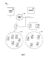
FIG. 2 is a generalized block diagram of a communications network including a LAN 200 and LAN 206. The LANs connect nodes 202 and access points 201. As shown, LAN 200 has two access points, and LAN 206 has once access point. A domain name server (DNS) 203 is connected to LAN 200 and LAN 206 through access point 201 to a communications network 204. In the presently preferred embodiment, DNS server 203 is capable of receiving and processing dynamic updates, thus providing a dynamic DNS service. Dynamic updating of DNS is done according to IETF RFC 2136. Communications network 204 may be any type of communications network including, without limitation, a LAN, WAN, wireless, fixed line, private network, virtual private network, etc. In the presently preferred embodiment the communications network 204 is a wide area network, and may use one or more communications protocols such as IPv4 or IPv6. One or more computing devices 205 connect to the communications network 204. A message to a node 202 from the computing device 205 may be sent using a network address for the node. Computing device 205 may be any device, combination of devices, network management system, server, back office systems (BOS), computers, network devices, communications devices, software application or component which is capable of communicating with an access point or node via the communication network 204. A second LAN 206 may also be connected to the DNS server 203 and the communications network 204. A DNS server may be dedicated to a single LAN, or two or more LANs may share a DNS server. As shown, LAN 200 and LAN 206 do not overlap, in that none of the nodes, and none of access points shown are members of both LAN 200 and LAN 206. Alternate embodiments may have one or more LANs which overlap, with one or more nodes and/or access points common to one or more LANs. Alternate embodiments may have additional LANs, which may or may not overlap with each other. In the presently preferred embodiment, the network address of a node is obtained according to the process described in connection with FIG. 3 below.
DNS server 203 maintains network addresses for the nodes of the LAN network that it is associated with. As discussed above, a DNS server may be associated with one or more LANs and maintain the network addresses of nodes within one or more LANs. In one preferred embodiment, a node registered with several access points may have at least as many network addresses. The network addresses for the nodes may be included in the DNS server, or node route registry. Additionally, the DNS server may also maintain address allocation information such as node address allocation indicator (or node preference indicator). Table 1 below shows some of the information which may be included in maintaining network addresses for nodes in a LAN. The resource records maintained in the DNS server may include:
TABLE 1
Resource Node Network Node Node Address
Record Type Address Name Preference Indicator
AAAA ADDR1 MAC1 50
ADDR2 30
ADDR2 10
AAAA ADDR4 MAC2 80
AAAA ADDR5 MAC3 44
ADDR6 20
As illustrated in Table 1, in the presently preferred embodiment the node name is the MAC address of the node. However, other embodiments may use other names for the node, which may or may not include or be based upon the MAC address. Further, the Resource Record (RR) Type in table 1 may be an IPv6 type.
Information in the route registry may be updated according to multiple criteria, including periodically or in the event one or more criteria are satisfied.
For illustration purposes only one DNS server is shown and discussed below. Alternate embodiments, however, may use multiple DNS servers.
Alternate embodiments of the DNS resource records may include additional information or may exclude some of the information included in Table 1. Additionally, while Table 1 includes information on only three nodes, alternate embodiments of a route registry could have information on more or fewer nodes. While Table 1 includes up to three network addresses for a given node, alternate embodiments of a route registry may have any number of addresses per node.
FIG. 3 is a generalized flow diagram of a process 300 for obtaining a network address of a node. At step 301 a node intending to send a packet or a message to a node makes a DNS resolution request to a DNS server. The DNS resolution request includes a node identifier, typically the node name. The node identifier may be any combination of letters, numbers, symbols or characters. As described above in connection with Table 1, in one presently preferred embodiment the node identifier is the MAC address of the intended node. As shown in Table 1, the source or requesting node includes information specifying the node's identifier, the node's network address, network address preference, etc. At step 302 the DNS server receives the DNS resolution request for the intended node. At step 303 the DNS server responds with a network address for the node associated with the node identifier. In the presently preferred embodiment, the network address is an IP address. In one presently preferred embodiment, the resource record AAAA relates to an IPv6 address. IPv4 resource record (RR) may be A, PTR, CNAME type. The DNS server may have more than one network address for a given node. For example, multiple IPv6 addresses may be associated with a given node (or access point, or BOS, or any other device on a network). If multiple addresses are associated with a given node, at step 302 the DNS server may provide all available network addresses for a particular RR. Alternatively, the DNS server may select a subset of the network addresses associated with the intended node. For example, the DNS server may choose one network address to include in the response to the electronic device. If a subset of network addresses associated with the intended node is selected the selection may be based upon a connection cost, upon a preset selection criteria, upon a policy (for example, the electronic device intending to exchange messages with the node, the type, size or priority of the message, some aspect of the use of the message by the node, or the nature of the network device e.g.: a server, a network management system, a billing system, an outage management system, a utility management system, etc.) or upon some other criteria. If multiple network addresses are provided in the DNS resolution response, the response may also include the corresponding node address preference indicators. At step 304 the node receives the DNS resolution response from the DNS server. At step 305 the node sends its message using a network address received from the DNS server.
The address used to send the message from the node and/or an electronic device to the intended node or electronic device may correspond to one or more access points. For example, in an IPv6 LAN the network address would typically be an IPv6 address. In the event there is more than one access point, the IPv6 prefix of the network address may be associated with a given access point. In this manner the IPv6 network address may allow a given access pint to be used to transmit a message to the network destination. If a node is in a LAN with multiple access points, the node may have more than one IPv6 address associated with the node.
Example 1 Multi Ingress Using IPv6 Network Addressing
The present example has a given node with a node name of Node1. Node1 has two IPv6 network addresses associated with it. The route registry entry for Node1 may read:
DDNS Route Registry
Resource Node Address
Node Record Preference
Name Type Node Network Address Indicator
. . . . . . . . . . . .
MAC1 AAAA 2001:2105:20ae:1:225:3400:208:aa03 50
2001:2105:20ae:2:225:3400:208:aa03 30
. . . . . . . . . . . .

Node1 connects to a communications network through two access points: AP1 and AP2. AP1 is associated with IPv6 prefix 2001:2105:20ae:1::/64 and AP2 is associated with IPv6 prefix 2001:2105:20ae:2::/64. A network device, for example a back office system which manages outage detection, intending to send a message to Node1 may receive either network address associated with Node1 from the route registry of the DNS server (or may receive both network addresses). A message sent from the outage detection system to Node1 using the network address with prefix 2001:2105:20ae:2::/64 would be routed through AP2. A message sent from the outage detection system to Node1 using the network address with prefix 2001:2105:20ae:1::/64 would be routed through AP1.
FIG. 4 is a generalized communications flow diagram illustrating process 400 for registering a nodal device with an access point. Registering a nodal device to obtain a network address may apply to any format or protocol of network addresses. In one presently preferred embodiment, the LAN may be using IPv6 protocols (exclusively or in parallel with IPv4 protocols). For discussion purposes, process 400 will describe nodes of a wireless LAN using IPv6 network addresses. In a presently preferred embodiment, Node M initiates a discovery process and identifies its neighbor nodes and the access points of one or more LANs which provide egress and ingress. Node M may further initiate a routing analysis to identify a preferred set of one-hop neighbors who provide egress via one or more access points at the lowest path cost. It may then commence registration process with one or more APs and the affiliated DNS servers. At 401 node M sends a layer 2 registration message to an access point AP. At 402 the AP responds with a layer 2 acknowledgement message including an IPv6 prefix which is associated with the AP. Additionally, the acknowledgement message may include configuration information. In a presently preferred embodiment, the configuration information includes information which allows node M to register with a DNS server. In Another embodiment the AP may proxy the DNS request on behalf of node M. At 403 node M receives the layer 2 acknowledgement message and sends a layer 3 IPv6 registration message to the DNS. In one presently preferred embodiment, the IPv6 registration message to the DNS includes the IPv6 address for node M, which utilizes the IPv6 prefix received from the AP and a unique IPv6 “suffix”, to complete an IPv6 address for node M. This is done consistent with stateless autoconfiguration steps of RFC 2462. In one preferred embodiment, the IPv6 suffix is based upon the MAC address of the node M. Alternate embodiments may use other suffixes not based upon the MAC address to create a unique IPv6 address for the node M. Note, the IPv6 address for node M need not be globally unique.
At 404 a layer 3 acknowledgement message is sent from the DNS to the node M and received by the node M at 405. The layer 3 acknowledgement message may include confirmation of the registration of node M's registration with the DNS server, and may include additional information.
While process 400 only shows the registration of one node with one access point, in the presently preferred embodiment all nodes would register with at least one access point. Additionally, in one presently preferred embodiment nodes would register with more than one access point on their LAN in the event there is more than one access point on the LAN associated with the node. A node may even register with all the access points on the LAN the node is associated with.
In the presently preferred embodiment, a given node may have more than one unique IPv6 address associated with the node. If, as described above, a node's IPv6 address is determined from the IPv6 prefix of an access point and a unique component (e.g., the MAC address of the node) then if the node registers with multiple access points the node will be associated with multiple unique IPv6 addresses. In this manner nodes may be multihomed.
Node M may send a layer 3 SNMP TRAP or INFORM message to a back office system BOS at 406. Alternatively, the DNS server may signal the BOS via SNMP. Preferably, the SNMP TRAP or INFORM message will include at least one IPv6 address of the node M (and may include multiple network addresses associated with node M). At 407 the BOS receives the SNMP TRAP or INFORM message and replies with a layer 3 message such as a GMI (Generic Management Interface) data query. GMI data query message may request information on node M. For example, if node M is a meter in a utility network, the GMI data query message may request information on the configuration settings of the meter, status of the meter, information on the metered commodity, etc. At 408 node M receives the data query message and sends a data response message. At 409 the BOS receives the data response message from node M.
The BOS may request the network address of a given node at any time. For example, if the BOS has not received a message from node M when a message was expected, the BOS may query node M. If the BOS does not already have the network address of node M, or, as in one presently preferred embodiment, if the network is configured to request a network address unless the BOS is responding to a message received, the BOS may perform a lookup (i.e. a DNS resolution request) with the DNS server. At 410 the BOS sends an IPv6 network address lookup message for node M to the DNS server. At 411 the DNS server responds to the BOS with an IPv6 address for node M to the BOS (if the DNS server has a network address for node M, otherwise the DNS server may respond that it does not have a network address for node M). The IPv6 address for node M is received at 412.
In the event the node is not registered, or if the BOS does not receive a network address for the node, the BOS may attempt to programmatically derive the IP address or may attempt to generate an IP address. The BOS may create an ad-hoc IPv6 address using the AP's IPv6 address and the node's MAC address (as described above). The BOS may also send an IPv6 message to the AP requesting the AP to forward a message to the node based upon the node according to the node's unique MAC identifier. Alternatively, the BOS may request the AP ping the node to determine the network address of the node and/or inquire into the results of the registration process.
In the event node M encounters a problem, for example loss of power, a security incident, a problem with its hardware or software, a network problem, etc., node M may send a message indicating a problem to the BOS (or to any device reachable by node M) such as an SNMP TRAP or INFORM message. In the event of a loss of power, the node M may send a “last gasp” message. At 413 node M sends a last gasp message to the AP. Typically, the later 2 last gasp message is very short with only the essential information to conserve node's and network's resources, so the message is received reliably by other neighbor nodes and the corresponding AP. At 414 the AP receives the last gasp message from node M, and in the presently preferred embodiment packs an SNMP TRAP or INFORM PDU (Protocol Data Unit or SNMP packet) with L2 “last gasp” messages and forwards them to the BOS which indicates the AP has received a last gasp message from node M.
Example 2 Network Addressing for Transportation Nodes
The present example has a given node that is a transportation device as shown in FIG. 5. Specifically, Node H is a hybrid car which may have its batteries charged from an electric grid. Upon plugging Node H into an electrical outlet node H attempts to establish communication with an electrical utility billing BOS called BOS-HB. In the present example Node H is within the coverage area of LAN-7, a wireless communications network using the IPv6 protocol. Node H sends a layer 2 registration request message to at least one access point within LAN-7. AP1, an access point with LAN-7 responds with its IPv6 prefix, which is 4ea3. Node H uses the received prefix from AP1 to create a unique IPv6 address. Node H uses the MAC address of a network card in Node H, along with the IPv6 prefix from AP1, to create the unique IPv6 address. Node H sends a layer 3 registration message to a DNS server associated with LAN-7 and receives an acknowledgement from the DNS server. Node H also registers with a second access point on LAN-7 called AP2. AP1 and AP2 are both capable of communicating with BOS-HB through a communications network. AP2 sends Node-H its IPv6 prefix of 21ff, which Node H uses to create a second unique IPv6 address associated with AP2. Node H then sends an SNMP TRAP or INFORM message to BOS-HB indicating that it is on LAN-7. Additionally, the message to BOS-HB includes information to alert BOS-HB that Node H is currently connected to the electrical grid and receiving power to recharge the batteries of Node H. BOS-HB sends Node H messages to inquire into the electrical usage of Node H and also sends messages to check if Node H is still on the network. Prior to sending a message to Node H, BOS-HB performs a lookup of Node-H's network address with the DNS server. The DNS server, in responding to lookup requests corresponding to Node-H, may determine which of the two unique IP addresses associated with Node H to provide BOS-HB. In this example embodiment, the route registry of the DNS server includes a unique preference indicator associated with the IPv6 addresses corresponding to Node H. The preference indicator specifies that AP2 is preferred over AP1, as AP2 has a more reliable connection with AP2 than with AP1. Thus, the DNS server replies to BOS-HB with the network address associated with AP2. BOS-HB then uses the network address associated with AP2, which then routes messages to Node-H through AP2. In the event of a failure to deliver a message from BOS-HB to Node-H through AP2, BOS-HB (or another device on the network) may request and receive the next most preferred network address associated with Node-H, and resend the failed message using the next most preferred network address for Node-H. As the next most preferred network address for Node-H corresponds to AP1, the retry of the failed message is routed through AP1 to Node-H. In response to the failed delivery message to the network address associated with AP2, the DNS server may change the preference indicators associated with one or more network addresses associated with Node-H, and may also change the preference indicators of other nodes on according to one or more criteria (e.g. proximity to Node-H, dependence on AP2, dependence on Node-H, etc.). The request to change the preference indicator in the DDNS registry may originate from any one of Node-H, the BOS-HB, AP-1, AP-2.
Node H responds to the request from BOS-HB received from AP2 by sending a packet including the network address of Node H. If the included network address includes the prefix of AP1, the pack may be routed through AP1 to BOS-HB, thus allowing a network address to determine which access point, from among multiple access points, to use in egressing from LAN-7. Node H may select which of multiple network addresses associated with Node H to include in packet's header sent from Node H. By routing packets based upon the access point prefix included in the Node H, the egress point of the LAN may be selected, allowing control of egress in multi-egress embodiments.
As Node H is a mobile node capable of moving from one location to another (which may result in moving out of direct contact with a given AP, node or LAN), the AP may deregister a mobile node. For example, mobile nodes may be deregistered if they have not been in communication with the AP for a preset or configurable, period of time. Additionally, or alternatively, mobile nodes may send information to one or more APs not to deregister them, or policies at the AP may decide not to deregister a given mobile node based upon one or more characteristics.
System Components in Support of IPv6 Utility Networks
Utility networks capable of supporting communication using IPv6 addressing and protocols may use a variety of devices capable of communicating, preferably, using IPv6. In the presently preferred embodiment, system components such as a utility node, an access point, and a back office system would have IPv6 functional support integrated into the respective system component. Example preferred embodiments of IPv6 capable systems components are shown and described in connection with FIGS. 6, 7 and 8.
FIG. 6 is a generalized block diagram of a node 600 as may be found in communications network 600 described above. In one preferred embodiment, node 600 may include a device information controller 601, memory 602, LAN radio controller and interface 603, private radio controller and interface 604, meter and external data interface 605, and IPv6 protocol controller 609. Meter and external data interface 605 may connect to a slave device 606, local meter data interface 607, and or an external sensor device output interface. IPv6 protocol controller 609 may receive and send IPv6 packets, and may also create or maintain IPv6 tunnels or encapsulate/de-encapsulate packets as needed.
While the example node 600 does not include a meter for metering a commodity, alternate embodiments may include metering capability.
While the example node 600 does not include radios such as a private network radio or LAN radio, alternate embodiments of the node may include one or more radios.
While example node 600 is described as a single device, alternate embodiments may use multiple computers, electronic devices or radios in implementing example node 600.
FIG. 7 is a generalized block diagram of an access point 700 as may be found in communications network 600 described above. Access point 700, which may also act as a gateway to nodes in a network such as a wireless LAN, may include an access point information controller 701, memory 702, a WAN interface 703, a private wireless radio network controller 704, a wireless LAN radio controller and interface 705, and network IDs IPv6 protocol controller 706. The network IDs IPv6 protocol controller 706 may also include a tunnel broker, or a tunnel broker may be included separately from the router and 6-in-4 formatter in embodiments utilizing a tunnel broker.
While the example access point 700 does not include radios such as a private network radio, WAN or LAN radio, alternate embodiments of the access point may include one or more radios.
While the example access point 700 is distinct from a meter or other device in the network (e.g. a relay, etc.) alternate embodiments could combine the functionality of a node, meter, relay, or any other device or system in the network.
While access point 700 is described as a single device, alternate embodiments may use multiple computers, electronic devices or radios in implementing access point 700.
FIG. 8 is a generalized block diagram of back office system 800 as may be found in communications network 500 described above. Back office system 800 may include a communications server 801, a wireless private network communications controller 802, a router and 6-in-4 formatter 803, an application server 804 and a database server 805. Wireless private network communications controller 802 may communicate with a private wireless network. The router and 6-in-4 formatter 803 may communicate with the WAN. The router and 6-in-4 formatter may also include a tunnel broker, or a tunnel broker may be included separately from the router and 6-in-4 formatter in embodiments utilizing a tunnel broker. The WAN may be the internet, an intranet, or any other type of wide area network. Alternatively, the formatter may be a 6 to 4 formatter for IPv6 encapsulation. Application server may be any type of application which may be used in a utility network. Examples, without limitation, include billing applications, accounting applications, outage detection and/or management applications, configuration and or provisioning applications, network applications such as a proxy server, a DNS or DNS server, a storage, back-up and or recovery application, a customer interface application (for example, an interface application to allow a customer to control aspects associated with a node or to control aspects of a node), a node manager, a content management or delivery system, a communication manager or communication providing application, etc.
While back office system 800 is described as a single entity, it may be implemented on one or more computers, for example on multiple servers in a data center. The described components of back office system 800 may be implemented on different computers, or may be implemented across multiple computers. Additionally, back office system 800 may be implemented across multiple computers in multiple locations or on multiple networks. Back office system 800 may also aggregate or include multiple applications. For example, a back office system may include both an accounting system as well as a customer billing system. As another example, back office system may include a billing system and a proxy server. Additional combinations of any number of applications may be included in additional alternate embodiments.
Utility Node Subnetworks
FIG. 9 is a generalized block diagram illustrating a utility node sub-network 900. Network 900 may include a utility node 901. The utility node may include a commodity meter, or may interface with a commodity meter. Utility node 901 is capable of communicating with a communications network 902. In one preferred embodiment, utility node 901 includes a wireless radio capable of communicating with a wireless LAN using IP protocols (IPv4 or IPv6). Utility node 901 also includes an in-premise device interface 903. In-premise device interface 903 connects to in-premise devices 904 to provide a communications link between the utility node and the in-premise devices. Additionally, the utility node may provide a communications link between the in premise devices 904 and the communications network 902 connected to the utility node.
In one presently preferred embodiment, the utility node in-premise device interface 903 assigns a network address to in premise devices which it is capable of communicating with. In one possible embodiment, the network address assigned by the in-premise device interface 903 is an IP address. Preferably, the network address assigned to an in-premise device is unique within communications network 902. The in-premise device interface 903 may also share, or allow sharing, of the network address assigned to an in-premise device outside of the subnet within the premise. Thus, in-premise devices are directly addressable from outside the sub-network of the premise. The utility node proxies the assigned IP address on behalf of the corresponding in-premise device, allowing other nodes in the communication network to communicate with the in-premise device using the assigned IP address. Example 3 illustrates this through one possible embodiment.
Example 3 In-Premise Communication Using IPv6 Network Addressing
The present example is of a utility node with a node name of Node 31 Cedar Ave. Node 31 Cedar Ave is deployed in a residential unit (a home) and is capable of communicating with in-premise devices (devices within the home) through multiple protocols and communications technologies. For example, utility node 31 Cedar Ave may communicate with devices using ether a wireless personal area network (WPAN) or using PLC (Power line Carrier) communications with PLC capable devices connected to the home's power grid. The example home includes five in-premise devices, a thermostat communicating via WPAN, a pool pump communicating via WPAN, a freezer communicating via PLC, and a home entertainment system communicating via WPAN.
The WPAN may be any one, or any combination, of network technologies or standards including, without limitation, Bluetooth, ZigBee (IEEE 802.15.4), IrDA, UWB (IEEE 802.15.3), Dust TSMP, Insteon, other technologies based upon IEEE 802.15, etc.
Utility Node 31 Cedar Ave communicates wirelessly with a utility network using IPv6 communications protocols. The utility network includes other utility nodes and at least one access point, as well as a BOS for managing node 31 Cedar Ave.
Utility Node 31 Cedar Ave includes an electricity usage meter which monitors and reports the electrical usage of the home. Additionally, Node 31 Cedar Ave includes an interface for other commodity meters, which is connected to a natural gas meter which monitors and reports the natural gas usage of the home.
Node 31 Cedar Ave assigns an IPv6 address to each of these in-premise devices. Node 31 Cedar Ave shares the assigned IPv6 address for the thermostat, pool pump, freezer and entertainment system with communications network. Specifically, the network addresses of the in-premise devices are shared with an in-premise management portal which is connected to the utility network and which allows the homeowner to monitor and control the in-premise devices. The network addresses of one or more in-premise devices may also be proxied by Node 31 Cedar Ave within communications network or which may communicate through the communications network with Node 31 Cedar Ave.
Through the in-premise management portal the homeowner (or others) may communicate with the in-premise devices using the assigned IP address. Node 31 Cedar Ave receives packets intended for in-premise devices, identifies the intended device according to the assigned IP address, and forwards the payload of the packets to the intended device over the appropriate in-premise communication system (WPAN, PLC, etc.). Similarly, communication signals from the in-premise devise received over the in-premise communication system is input into the payload of a packet(s) and send to the in-premise management portal, including the network address assigned to the in-premise device.
The in-premise registry entry for the in-premise devices may read:
In-Premise Registry
In-Premise Assigned IPv In-Premise
Device
6 Network Communication Native
Name Address Technology Address
Thermostat Address
1 ZigBee Z1
Freezer Address 2 PLC PLC1
Pool Pump Address 3 ZigBee Z2
Entertainment Address 4 ZigBee Z3
System
Node 31 Cedar Ave uses the assigned network addresses and the in premise communication technology to allow communication between the in-premise devices and outside of premise communications networks.
In one preferred embodiment the utility node may also maintain an access control list (ACL) for in-premise devices. Using the ACL, the utility node allows access to an in-premise device according to the ACL. For example, the ACL may specify that a home security system may only allow access from a security portal. Any device or system attempting to communicate with the home security system will be denied access unless it provides the appropriate verification information specified in the ACL as corresponding to the security portal.
The utility node ACL may also specify service ports or network daemon names which are allowable for either, or both, inbound and outbound traffic.
In one presently preferred embodiment, the utility node may assign routable network addresses to in-premise devices. In premise devices may not be capable of using the network address, as in Example 3 above, where WPAN and PLC devices use their own network address and have assigned an IP address. Thus, the network address assigned the in-premise device is proxied by the utility node. In embodiments using IPv6, an access point may assign a portion of its allocated IPv6 addresses to the utility node. In turn, the utility node may allocate addresses to in premise devices from the IPv6 addresses assigned the utility node. In one preferred embodiment, the AP may allocate a block of continuous addresses to one or more utility nodes. The utility nodes may then assign any of the allocated addresses, or portions of them, to in-premises devices.
The network address assigned a device may be, partially or entirely, based upon the MAC address of the utility node communicating with the device, an access point, or the device itself.
Additionally or alternatively, rules or policies may be used to determine the allocation of addresses to in premise devices. Rules may be based upon the device type, device attributes, network technology or network protocol used by the device, the device's commodity usage type (e.g. electric, gas, water, etc.), the device's commodity usage history or characteristic (e.g. high usage, moderate usage, etc.), the premise or section of a premise the device is physically located in, or assigned attributes of the device (e.g. the importance of a device, the use of a device such as medical equipment, fire suppression equipment, security equipment, emergency response equipment, etc.), or upon attributes assigned by a user of the device or the owner/operator of the premise. Rules may also combine multiple factors listed above, for example considering the type of device, the physical premise, the electrical power consumption, and whether the device is related to security or emergency response.
Additionally or alternatively, some network addresses may be set aside for particular devices, uses, users, etc. For example, certain network addresses may be set aside for emergency personnel or their equipment. Thus, a mobile in-premise device of an emergency responder which appears on a given in-premise subnet may be assigned an address from a set-aside group of addresses for such devices of emergency responders. The address given from the group of address set aside may also be allocated according to a rule, for example assigning an address based upon the type of responder (police, fire, EMT, etc.) their affiliation or organization (department, precinct, etc.) the device type, or any other attribute of the organization, purpose, device, etc.
Example 4 illustrates one possible embodiment for implementing allocation of addresses to utility nodes and the assignment of allocated addresses to in-premise devices using utility nodes.
Example 4 Assigning In-Premise IPv6 Network Addresses
A utility node with a node name of Meter HM is deployed in a residential unit (a home) and is capable of communicating with in-premise devices (devices within the home or neighboring homes) through multiple protocols and communications technologies. Additionally, Meter HM also includes a commodity meter which meters the electricity used in the home. Meter HM may communicate with devices using either WPAN or PLC, with PLC capable devices connected to the home's power grid. The home includes six in-premise devices which may communicate with Meter HM: a thermostat communicating via WPAN, a freezer communicating via PLC, a home alarm system communicating over WPAN, a video camera which monitors a portion of the home and communicates over WPAN, a health monitoring system which may monitor the health of an elderly relative and which communicates over WPAN, and a home entertainment system communicating via WPAN.
Meter HM communicates wirelessly with a utility network using IPv6 communications protocols. The utility network includes other utility nodes and at Access points AP214, AP137 and AP8, as well as a BOS for managing Meter HM. The BOS also includes a customer portal which allows the homeowner to either monitor or control, or both, some or all of the in premise devices.
Access points AP214, AP137 and AP8 each have a /64 allocation of IPv6 addresses. Access point AP137 has allocated a /125 of IPv6 addresses to utility node Meter HM. Meter HM selects addresses from its /125 allocation of IPv6 addresses to assign addresses to the in-premise devise which register with it. Meter HM assigns addresses to the thermostat communicating via WPAN, the freezer communicating via PLC, the home alarm system communicating over WPAN, the video camera communicates over WPAN, the health monitoring system communicating over WPAN, and the home entertainment system communicating via WPAN. In the event one or more in-premise devices is removed, or unregistered from Meter HM then Meter HM may reassign the network address assigned to the removed or unregistered in-premise device to another in premise device.
Allocation of blocks of addresses to utility nodes may be segregated according to various criteria. For example, different sections of the utility network, geographically or logically, may have address blocks allocated from a subset of available address blocks.
While the above example embodiments had the in-premise devices communicate with a utility node which is assigned to (or installed at) the some premise of the utility node, alternate embodiments may allow in-premise devices to communicate via utility nodes from neighboring premises.
While the above example used continuous blocks of a given size according to CIDR (Classless Inter-domain routing) notation, alternate embodiments could use address blocks of any size, whether continuous or non-continuous.
Transit of Packets from an IPv6 Node Through IPv4 Network
Determination of whether to use “6 to 4” or “6 in 4” communication through an IPv4 network may be made by the access point, the back office system, or another component of the system. Communication between an IPv6 node in the utility network through an IPv4 network may be through either “6 to 4” or “6 in 4” communication, according to the type of node, the type of network, the selected access point, the back office system, the type of message, the contents of the message, the desired security level, etc. For example, for increased security “6 in 4” communication may be used. Note, “6 in 4” communication is often referred to as tunneling, whereas “6 to 4” communication is often referred to as network address translations (NAT) or packet encapsulation.
FIG. 10 is a generalized block diagram illustrating a network 1000 where an IPv4 tunnel connects an IPv6 LAN to and IPv6 back office system. Network 1000 includes two local area networks 1001 and 1002. LANs 1001 and 1002 include nodes 1003. In the presently preferred embodiment, nodes 1003 are utility nodes. LAN 1002 is connected to access point AP1 1004. LAN 1001 is connected to access points AP2 1005 and AP3 1006. Access point AP1 1004 and access point AP2 1005 connect to communications network 1007. Access point AP3 1006 connects to communications network 1008. In the presently preferred embodiment, communications networks 1007 and 1008 are wide area networks. Back office system BOS-1 1009 connects to WAN 1007. Back office system BOS-2 1010 connects to WAN 1007 and WAN 1008. Back office system BOS-3 1011 connects to WAN 1008.
In the example embodiment, LANs 1001 and 1002 communicate using the IPv6 protocol. Similarly, WAN 1008 utilize the IPv6 communications protocol. Access point AP3 1006, connecting LAN 1001 to WAN 1008, utilizes IPv6. Back office Systems BOS-1 1009, BOS-2 1010 and BOS-3 1101 all utilize the IPv6 communications protocol.
WAN 1007 is an IPv4 network, and does not support IPv6. Access points 1004 and 1005 which connect LAN 1002 and 1001, respectively, to WAN 1007 are capable of communicating using IPv6 and in participating in a mechanism that facilitates transit of IPv6 packets through WAN 1007 to BOS 1009 and 1010, and vice versa.
A message from a node 1003 on LAN 1002, intended for BOS-1 1009 or BOS-2 1010, is sent using and IPv6 address and packet format to access point AP1 1004. AP1 1004 creates and uses an IPv6 tunnel (dynamically or manually configured) through WAN 1007. An IPv6 packet from a node 1003 on LAN 1001 to BOS-2 1010 may route the packet through WAN 1007 or through WAN 1008. If the IPv6 packet is to be routed through WAN 1008, AP3 1006 is used and as WAN 1008 is an IPv6 network, no tunneling, translation or encapsulation need be performed. However, if the packet is routed through WAN 1007, then AP2 1005 is used an the IPv6 packet from node 1003 will either be passed through a “6-in-4” tunnel, as described in FIG. 10, or may be encapsulated in an IPv4 packet for transit through WAN 1007 in a 6 to 4 virtual tunnel, as described below in connection with FIG. 12.
As shown in FIG. 11, packet flow between the access point associated with the IPv6 LAN and the BOS is through the IPv4 WAN.
FIG. 12 is a generalized block diagram illustrating a network 1200 where IPv6 packets are passed through an IPv4 WAN. Network 1200 may include two local area networks 1201 and 1202. LANs 1201 and 1202 include nodes 1203. In the presently preferred embodiment, nodes 1203 are utility nodes. LANs 1201 and 1202 communicate with nodes 1203 using IPv6 protocols and addressing. LAN 1202 is connected to access point AP1 1204. LAN 1201 is connected to access points AP2 1205 and AP3 1206. Access point AP1 1204 and access point AP2 1205 connect to communications network 1207. Access point AP3 1206 connects to communications network 1208. In the presently preferred embodiment, communications networks 1207 and 1208 are wide area networks which communicate using IPv4 protocols and addresses. Back office system BOS-1 1209 connects to WAN 1207. Back office system BOS-2 1210 connects to WAN 1208. Back office system BOS-3 1211 connects to WAN 1208.
A node 1203 on LAN 1201 or 1202 sending a message to one, or more, of the back office systems BOS-1, BOS-2, and BOS-3 must pass through one or more IPv4 WANs 1207 or 1208.
Node 1203 on LAN 1201 or 1202 sends an IPv6 packet using and IPv6 address to the appropriate access point to communicate with the intended back office system. In the event BOS-1 1209 is the intended back office system, AP1 1204 may be used to connect to WAN 1207. AP1 1204 receives the IPv6 packet from node 1203, and may encapsulate the received IPv6 packet in the payload portion of an IPv4 packet. AP1 may have or acquire a global IPv4 address for itself for this purpose. The IPv4 header with Protocol 41 is prepended to the IPv6 packet. An IPv4 address associated with BOS-1 is used in the IPv4 packet with the IPv6 packet as payload (the IPv6 packet is a datagram within the IPv4 packet). The IPv4 address of BOS-1 for the prepended packet header can also be derived from the IPv6 destination address of the encapsulated packet by extracting the 32-bits following the IPv6 destination address' 2002::prefix. In such an embodiment, the IPv4 source address in the prepended packet is the IPv4 address of AP1. The packet IPv4 packet is then transmitted to BOS-1 1209 through WAN 1207. BOS-1 1209 receives the IPv4 packet, and extracts the encapsulated IPv6 packet. The payload of the IPv6 packet is extracted by the BOS-1 1209. In this manner AP1 1204 and BOS-1 1209 use a “6 to 4” tunnel translation though IPv4 WAN 1207 without establishing an explicit tunnel.
Alternatively, AP1 1204 receiving the IPv6 packet from node 1203, and encapsulate IPv6 packets within UDP packets for transmission to BOS-1 1209 using WAN 1207. As above, in this manner AP1 1204 and BOS-1 1209 are able to exchange IPv6 packets through IPv4 WAN 1207.
BOS-1 1209 intending to send a message to node 1203 through IPv4 WAN and IPv6 LAN may send an IPv4 packet to AP1 1204 through WAN 1207. AP1 1204 may prepend an IPv6 prefix to the IPv4 address of the packet received from BOS-1 1209 and intended for node 1203, allowing the IPv4 address to be effectively converted for transmitting the received packet over IPv6 LAN 1201.
In yet another alternative embodiment, an IPv6 “explicit tunnel” may be created through one or more IPv4 WANs (or more than one IPv6 tunnels may be created through a given IPv4 WAN) as also discussed above in connection with FIG. 10. For example, Node 1203 on LAN 1201 or 1202 sends an IPv6 packet using and IPv6 address to the appropriate access point to communicate with the intended back office system. In the event BOS-1 1209 is the intended back office system, AP1 1204 may be used to connect to WAN 1207. AP1 1204 receives the IPv6 packet from node 1203, and may establish an IPv6 tunnel (or may access an established IPv6 tunnel) through IPv4 WAN 1207. A tunnel broker (not shown) may establish an IPv6 tunnel through IPv4 WAN 1207. This is a configured tunnel (referred to as 6 in4 tunnel) where the traffic between nodes on either side intended BOS and AP nodes will, in the presently preferred embodiment, always use this tunnel. A configuration script may be exchanged between the access point of the utility network and a back office system in establishing the tunnel through the wide area network. In one preferred embodiments, AP1 1204 establishes the IPv6 tunnel to BOS-1 1209. However, alternate embodiments may have one or more back office systems establish a “6 in 4” tunnel through a WAN to one or more access points. 6 in4 tunnel is a configured tunnel. In alternate embodiments, UDP encapsulation of IPv6 packets may also be used, for example to prevent the transiting packet through WAN 1207 is not blocked by any NAT (Network address Translation) device that may be present in WAN 1207.
The IPv6 packet IPv4 received by AP1 1204 is transmitted to BOS-1 1209 via the “6 in 4” tunnel through WAN 1207. BOS-1 1209 receives and processes the IPv6 packet. Similarly, BOS-1 1209 may send IPv6 packets to Node 1203 through AP1 1204 using the “6 in 4” tunnel through WAN 1207.
Transit of IPv4 Packets Through an IPv6 Utility LAN Network
FIG. 13 is a generalized block diagram illustrating a network 1300 where IPv4 packets are passed through an IPv6 LAN. Network 1300 may include two local area networks 1301 and 1302. LANs 1301 and 1302 include nodes 1303. In the presently preferred embodiment, nodes 1303 are utility nodes. LAN 1302 is connected to access point AP1 1304. LAN 1301 is connected to access points AP2 1305 and AP3 1306. Access point 1304 and access point 1305 connect to communications network 1307. Access point 1306 connects to communications network 1308. In the presently preferred embodiment, communications networks 1307 and 1308 are wide area networks. Back office system BOS-1 1309 connects to WAN 1307. Back office system BOS-2 1310 connects to WAN 1307 and WAN 1308. Back office system BOS-3 1311 connects to WAN 1308.
Nodes 1312 on LAN 1301 are IPv4 nodes which communicate using IPv4, whereas LAN 1301 utilizes IPv6. Node 1312 sending a message to BOS 1310, which connects to LAN 1301 through IPv6 WANs and access points, may be accomplished by node 1312 sending an IPv4 packet on LAN 1301.
Node 1312 sends its IPv4 packet to AP2 for forwarding to BOS-1 1309. In this case, AP2 has the capability to read the destination header in the IPv4 packet but does not reformat the packet; the packet traverses to BOS-1 1309 or BOS-2 1310 over IPv4 WAN 1307; BOS-1 1309 and BOS-2 1310 both have the capability to strip the IPv4 packet, read the source information and the payload; BOS-1 1309 and BOS-2 1310 also generate IPv4 packets intended for IPv4 node 1312 for traverse through WAN 1307, and forwarding to node 1312 by AP2 1305.
In one possible alternative embodiment, AP2 1305 has the capability to map and convert the IPv4 address and headers to IPv6 and also read and map the payload on to IPv6 packet. From then on, the IPv6 packet traverses through WAN 1307 in a 6 to 4 or 6 in4 tunnels like all other IPv6 packets do; BOS 1309 and BOS 1310 receive and process the reformatted IPv6 packet, and also generate an IPv6 packet in any response to or communication with node 1312. The return IPv6 packet is converted back to IPv4 format by AP2 1305 before it is forwarded to node 1312.
In yet another possible embodiment, the IPv4 packet from node 1312 heading to BOS 1310 or BOS 1311 via IPv6 WAN is converted to IPv6 format by AP2 1305 or AP3 1306, and forwarded to BOS 1310 or BOS 1311 (in this manner, 6 in4 or 6 to 4 tunneling need not be involved).
The invention has been described with reference to particular embodiments. However, it will be readily apparent to those skilled in the art that it is possible to embody the invention in specific forms other than those of the preferred embodiments described above. This may be done without departing from the spirit of the invention.
Thus, the preferred embodiment is merely illustrative and should not be considered restrictive in any way. The scope of the invention is given by the appended claims, rather than the preceding description, and all variations and equivalents which fall within the range of the claims are intended to be embraced therein.

Claims (21)

What is claimed is:
1. A wireless communication system comprising:
a plurality of nodes that are part of a wireless local area network; and
a plurality of access points connected to the wireless local area network, the access points providing communication between at least one of the plurality of nodes and at least one wide area network;
wherein at least one of the plurality of nodes is configured to:
register with at least two of the plurality of access points; and
for each of the plurality of access points with which the at least one node registers, obtain a unique network address of the at least one node corresponding to that access point in response to registration, such that the at least one node obtains a plurality of unique network addresses each respectively associated with a corresponding one of the plurality of access points with which the at least one node registers,
wherein the at least one node is configured to forward, via at least one of the access points with which the at least one node is registered, multiple unique network addresses to an intended network destination accessible through the at least one wide area network, to provide the intended network destination with multiple routes to reach the node,
wherein the multiple routes are respectively associated with a corresponding one of at least two of the access points with which the node has registered.
2. The wireless communication system of claim 1, wherein the intended network destination is associated with a global network address, and
wherein the global network address associated with the intended network destination is used by the at least one node to send a message to the intended network destination.
3. The wireless communication system of claim 1, wherein at least one of the plurality of unique network addresses corresponding to the access point that the at least one node is registered with includes an address prefix associated with the access point the node is registered with.
4. The wireless communication system of claim 3, wherein the address prefix is an IPv6 address prefix.
5. The wireless communication system of claim 1, wherein at least one of the plurality of nodes is configured to communicate with a utility meter and transmit information on a metered commodity.
6. The wireless communication system of claim 1, wherein the at least one node is configured to receive a message routed through one of the access points the at least node is registered with via the unique network address obtained for the one of the plurality of access points.
7. A method of communicating in a network, comprising:
registering, by a node in a wireless local area network, with a plurality of access point devices that provide an interface between the wireless local area network and an external network;
receiving, by the node, a corresponding network address prefix for each of the plurality of access points the node registers with, respectively, such that the node receives a plurality of network address prefixes each respectively corresponding to one of the plurality of access points with which the node registers;
generating a plurality of unique network addresses for the node, each of the plurality of unique network addresses being based on a corresponding one of the plurality of network address prefixes; and
forwarding, by the node via at least one of the access points with which the node is registered, multiple unique network addresses to an intended network destination to provide the intended network destination with multiple routes to reach the node,
wherein the multiple routes are respectively associated with a corresponding one of at least two of the access points with which the node has registered.
8. The method of claim 7, comprising:
registering the unique network addresses with a dynamic domain name server associated with the external network to provide at least one network device in communication with the external network with a plurality of routes to reach the node,
wherein the plurality of routes are respectively associated with a corresponding one of the plurality of access points which received the sent registration.
9. The method of claim 7, comprising:
routing messages to the node according to one of the unique network addresses,
wherein the network address prefixes are IPv6 address prefixes, and
wherein the routed messages are routed through one of the access points corresponding to the IPv6 prefix, and one of the multiple unique network addresses for the node is chosen according to a network address preference indicator.
10. The method of claim 9, wherein the network address preference indicator is stored in a DNS server associated with the wireless local area network.
11. The method of claim 9, wherein the preference indicator corresponds to a configurable cost metric of packet delivery performance of a connection to the corresponding node.
12. The method of claim 9, wherein the preference indicator corresponds to a configurable cost metric of packet delivery performance of a connection to the corresponding node.
13. The method of claim 9, wherein the preference indicator corresponds to a configurable policy.
14. The method of claim 9, comprising:
selecting an alternate route upon failure of an initial packet delivery attempt.
15. The method of claim 9, wherein the preference indicator is based on at least one of reliability, speed, priority and link quality.
16. The method of claim 9, comprising:
modifying the preference indicator corresponding to the unique network address used to send a message to the node in response to a failed attempt to deliver a message to the node.
17. The method of claim 16, comprising:
modifying preference indicators of DNS entries corresponding to other nodes that are dependent on a node which failed to deliver the message to the node.
18. The method of claim 7, wherein the node is configured to communicate with a utility meter and transmit information on a metered commodity.
19. The method of claim 7, comprising:
communicating, via the node, with at least one in-premise device over a sub-network of a premises;
associating at least one of the network address with the in-premise device; and
sending an indication of the association of the network address with the in-premise device to at least one other node in the local area network.
20. The method of claim 7, comprising:
communicating, via the node, with at least one in-premise device over a sub-network of a premises;
receiving a block of network addresses from at least one of the access points in the local area network;
allocating a network address to the in-premise device from the received block of network addresses; and
sending an indication of the allocation of the network address with the in-premise device to at least one other node in the local area network.
21. A wireless communication system comprising:
a plurality of nodes that are part of a wireless local area network; and
a plurality of access points connected to the wireless local area network, the access points providing communication between at least one of the plurality of nodes and at least one wide area network;
wherein at least one of the plurality of nodes is configured to:
register with at least two of the plurality of access points; and
for each of the plurality of access points with which the at least one node registers, obtain a unique network address of the at least one node corresponding to that access point in response to registration, such that the at least one node obtains a plurality of unique network addresses each respectively associated with a corresponding one of the plurality of access points with which the at least one node registers,
wherein the at least one node is addressable using all of the plurality of unique network addresses obtained by the at least one node.
US14/518,475 2007-02-02 2014-10-20 Method and system of providing IP-based packet communications in a utility network Active US9178716B2 (en)

Priority Applications (1)

Application Number Priority Date Filing Date Title
US14/518,475 US9178716B2 (en) 2007-02-02 2014-10-20 Method and system of providing IP-based packet communications in a utility network

Applications Claiming Priority (4)

Application Number Priority Date Filing Date Title
US89932807P 2007-02-02 2007-02-02
US11/807,185 US8429295B2 (en) 2007-02-02 2007-05-24 Method and system of providing IP-based packet communications in a utility network
US13/834,727 US8892774B2 (en) 2007-02-02 2013-03-15 Method and system of providing IP-based packet communications in a utility network
US14/518,475 US9178716B2 (en) 2007-02-02 2014-10-20 Method and system of providing IP-based packet communications in a utility network

Related Parent Applications (1)

Application Number Title Priority Date Filing Date
US13/834,727 Continuation US8892774B2 (en) 2007-02-02 2013-03-15 Method and system of providing IP-based packet communications in a utility network

Publications (2)

Publication Number Publication Date
US20150039742A1 US20150039742A1 (en) 2015-02-05
US9178716B2 true US9178716B2 (en) 2015-11-03

Family

ID=39675706

Family Applications (10)

Application Number Title Priority Date Filing Date
US11/807,173 Active 2030-02-01 US8953610B2 (en) 2007-02-02 2007-05-24 Method and system for transit between two IPV6 nodes of a utility network connected VIA an IPV4 network using encapsulation technique
US11/807,177 Active 2028-10-13 US8489716B2 (en) 2007-02-02 2007-05-24 Method and system of providing network addresses to in-premise devices in a utility network
US11/807,184 Abandoned US20080186203A1 (en) 2007-02-02 2007-05-24 Method and system for packet transit through IPV4 networks connecting IPV6 nodes and LANs in a utility grid using tunneling technique
US11/807,185 Active 2030-04-27 US8429295B2 (en) 2007-02-02 2007-05-24 Method and system of providing IP-based packet communications in a utility network
US11/807,176 Active 2030-05-17 US8364846B2 (en) 2007-02-02 2007-05-24 Method and system of providing IP-based packet communications with in-premisis devices in a utility network
US13/834,727 Active 2027-07-23 US8892774B2 (en) 2007-02-02 2013-03-15 Method and system of providing IP-based packet communications in a utility network
US13/933,943 Active 2027-11-29 US9094458B2 (en) 2007-02-02 2013-07-02 Method and system of providing network addresses to in-premise devices in a utility network
US14/518,475 Active US9178716B2 (en) 2007-02-02 2014-10-20 Method and system of providing IP-based packet communications in a utility network
US14/600,427 Active US9288181B2 (en) 2007-02-02 2015-01-20 Method and system of providing IPv6 packet transit between two IPv6 nodes of a utility network connected via an IPv4 network using encapsulation technique
US15/040,422 Abandoned US20160165564A1 (en) 2007-02-02 2016-02-10 Method and system of providing ip-based packet communications in a utility network

Family Applications Before (7)

Application Number Title Priority Date Filing Date
US11/807,173 Active 2030-02-01 US8953610B2 (en) 2007-02-02 2007-05-24 Method and system for transit between two IPV6 nodes of a utility network connected VIA an IPV4 network using encapsulation technique
US11/807,177 Active 2028-10-13 US8489716B2 (en) 2007-02-02 2007-05-24 Method and system of providing network addresses to in-premise devices in a utility network
US11/807,184 Abandoned US20080186203A1 (en) 2007-02-02 2007-05-24 Method and system for packet transit through IPV4 networks connecting IPV6 nodes and LANs in a utility grid using tunneling technique
US11/807,185 Active 2030-04-27 US8429295B2 (en) 2007-02-02 2007-05-24 Method and system of providing IP-based packet communications in a utility network
US11/807,176 Active 2030-05-17 US8364846B2 (en) 2007-02-02 2007-05-24 Method and system of providing IP-based packet communications with in-premisis devices in a utility network
US13/834,727 Active 2027-07-23 US8892774B2 (en) 2007-02-02 2013-03-15 Method and system of providing IP-based packet communications in a utility network
US13/933,943 Active 2027-11-29 US9094458B2 (en) 2007-02-02 2013-07-02 Method and system of providing network addresses to in-premise devices in a utility network

Family Applications After (2)

Application Number Title Priority Date Filing Date
US14/600,427 Active US9288181B2 (en) 2007-02-02 2015-01-20 Method and system of providing IPv6 packet transit between two IPv6 nodes of a utility network connected via an IPv4 network using encapsulation technique
US15/040,422 Abandoned US20160165564A1 (en) 2007-02-02 2016-02-10 Method and system of providing ip-based packet communications in a utility network

Country Status (16)

Country Link
US (10) US8953610B2 (en)
EP (1) EP2127226B1 (en)
JP (1) JP5329433B2 (en)
KR (1) KR101434705B1 (en)
CN (2) CN101641908B (en)
AU (1) AU2008214466B2 (en)
BR (1) BRPI0806837A2 (en)
CA (1) CA2676656C (en)
DK (1) DK2127226T3 (en)
HK (1) HK1139530A1 (en)
MX (1) MX2009008085A (en)
MY (1) MY151825A (en)
RO (1) RO126258A2 (en)
RU (1) RU2479932C2 (en)
TW (5) TWI369101B (en)
WO (5) WO2008097447A1 (en)

Cited By (1)

* Cited by examiner, † Cited by third party
Publication number Priority date Publication date Assignee Title
US20150219463A1 (en) * 2014-02-04 2015-08-06 Korea University Research And Business Foundation Real-time transportation network topology control-combined traffic flow control and dynamic route guidance system using in-vehicle navigator with bidirectional communication and parking guidance and reservation system using the same

Families Citing this family (123)

* Cited by examiner, † Cited by third party
Publication number Priority date Publication date Assignee Title
US9001645B2 (en) * 2006-05-17 2015-04-07 Rajant Corporation System and method for packet delivery backtracking
US7532587B2 (en) * 2006-09-06 2009-05-12 Motorola, Inc. Method and apparatus for performing anonymous source routing
US8953610B2 (en) * 2007-02-02 2015-02-10 Silver Spring Networks, Inc. Method and system for transit between two IPV6 nodes of a utility network connected VIA an IPV4 network using encapsulation technique
US7957322B2 (en) 2007-02-02 2011-06-07 Silver Sring Networks, Inc. Flow-through provisioning in utility AMR/AMI networks
WO2008096273A2 (en) * 2007-02-09 2008-08-14 Business Intelligent Processing Systems, Plc System and method for performing payment transactions, verifying age, verifying identity, and managing taxes
US8477771B2 (en) * 2007-03-01 2013-07-02 Meraki Networks, Inc. System and method for remote monitoring and control of network devices
US8130700B2 (en) 2007-06-15 2012-03-06 Silver Spring Networks, Inc. Method and system for providing network and routing protocols for utility services
US7769888B2 (en) 2007-06-15 2010-08-03 Silver Spring Networks, Inc. Method and system for providing network and routing protocols for utility services
US8072951B2 (en) 2007-06-15 2011-12-06 Silver Spring Networks, Inc. Method and system for providing routing protocols in a frequency hopping spread spectrum network
US8233905B2 (en) 2007-06-15 2012-07-31 Silver Spring Networks, Inc. Load management in wireless mesh communications networks
US8279870B2 (en) 2007-08-01 2012-10-02 Silver Spring Networks, Inc. Method and system of routing in a utility smart-grid network
US8805552B2 (en) 2007-08-28 2014-08-12 Causam Energy, Inc. Method and apparatus for actively managing consumption of electric power over an electric power grid
US8806239B2 (en) 2007-08-28 2014-08-12 Causam Energy, Inc. System, method, and apparatus for actively managing consumption of electric power supplied by one or more electric power grid operators
US9130402B2 (en) 2007-08-28 2015-09-08 Causam Energy, Inc. System and method for generating and providing dispatchable operating reserve energy capacity through use of active load management
US9177323B2 (en) 2007-08-28 2015-11-03 Causam Energy, Inc. Systems and methods for determining and utilizing customer energy profiles for load control for individual structures, devices, and aggregation of same
US8280057B2 (en) * 2007-09-04 2012-10-02 Honeywell International Inc. Method and apparatus for providing security in wireless communication networks
WO2009055061A1 (en) 2007-10-25 2009-04-30 Trilliant Networks, Inc. Gas meter having ultra-sensitive magnetic material retrofitted onto meter dial and method for performing meter retrofit
CA2705093A1 (en) 2007-11-25 2009-05-28 Trilliant Networks, Inc. Communication and message route optimization and messaging in a mesh network
US8332055B2 (en) 2007-11-25 2012-12-11 Trilliant Networks, Inc. Energy use control system and method
EP2215556B1 (en) 2007-11-25 2019-08-28 Trilliant Networks, Inc. System and method for transmitting power status notifications in an advanced metering infrastructure network
US8138934B2 (en) 2007-11-25 2012-03-20 Trilliant Networks, Inc. System and method for false alert filtering of event messages within a network
US7940679B2 (en) * 2008-05-08 2011-05-10 Elster Electricity, Llc Power outage management and power support restoration for devices in a wireless network
US7783764B2 (en) * 2008-05-27 2010-08-24 Silver Spring Networks, Inc. Multi-protocol network registration and address resolution
TWI392317B (en) * 2008-05-27 2013-04-01 Silver Spring Networks Inc Multi-protocol network registration and address resolution
US8316136B2 (en) * 2009-05-22 2012-11-20 Silver Spring Networks, Inc. Multi-protocol network registration and address resolution
WO2010022535A1 (en) 2008-08-26 2010-03-04 上海贝尔股份有限公司 Method and device for transferring packet in ipv6 access node
WO2010027495A1 (en) 2008-09-04 2010-03-11 Trilliant Networks, Inc. A system and method for implementing mesh network communications using a mesh network protocol
US9743337B2 (en) * 2008-09-22 2017-08-22 Silver Spring Networks, Inc. Meshed networking of access points in a utility network
US8325060B2 (en) * 2008-09-22 2012-12-04 Silver Spring Networks, Inc. Transparent routing in a power line carrier network
AR074654A1 (en) * 2008-10-01 2011-02-02 Silver Spring Networks Inc METHOD AND SYSTEM FOR APPLYING ENVIRONMENTAL INCENTIVES
US8782746B2 (en) * 2008-10-17 2014-07-15 Comcast Cable Communications, Llc System and method for supporting multiple identities for a secure identity device
CN101447935B (en) * 2008-11-20 2011-12-21 华为技术有限公司 Data packet transmitting method, system and equipment thereof
US8289182B2 (en) 2008-11-21 2012-10-16 Trilliant Networks, Inc. Methods and systems for virtual energy management display
KR101277368B1 (en) * 2008-12-25 2013-06-20 미쓰비시덴키 가부시키가이샤 Communication management device, communication node, communication system, and data communication method
US9014832B2 (en) * 2009-02-02 2015-04-21 Eloy Technology, Llc Augmenting media content in a media sharing group
US8391194B2 (en) * 2009-02-13 2013-03-05 Qualcomm Incorporated High rate packet data (HRPS) idle state handout from femto access point to macro access network
US8874693B2 (en) * 2009-02-20 2014-10-28 Microsoft Corporation Service access using a service address
ES2502290T3 (en) * 2009-02-27 2014-10-03 Technische Universität Dresden Procedure and system for the communication of a resource generating and / or resource consuming apparatus with a central control unit
WO2010105038A1 (en) 2009-03-11 2010-09-16 Trilliant Networks, Inc. Process, device and system for mapping transformers to meters and locating non-technical line losses
EP2244066A1 (en) * 2009-04-21 2010-10-27 Alcatel Lucent Method and system for transferring information, as well as a master device, a slave device and a central instance for such system
US8719337B1 (en) * 2009-04-27 2014-05-06 Junaid Islam IPv6 to web architecture
KR101649578B1 (en) * 2009-05-13 2016-08-19 코닌클리케 필립스 엔.브이. A method for assigning a network address for communicating in a segmented network
TWI491300B (en) 2009-06-10 2015-07-01 皇家飛利浦電子股份有限公司 Wireless network system, joining device for use in a wireless network system, method of commissioning awireless network system and computer program product
US8730057B2 (en) * 2009-08-17 2014-05-20 Tendril Networks, Inc. AMR meter to ZigBee communications bridge
US8516141B2 (en) * 2009-09-01 2013-08-20 Konica Minolta Laboratory U.S.A., Inc. Method and system for modifying and/or changing a MAC ID utilizing an IPv6 network connection
US8037343B2 (en) * 2009-09-15 2011-10-11 Verizon Patent And Licensing, Inc. Trap-based configuration audit
CN102045244A (en) * 2009-10-10 2011-05-04 中兴通讯股份有限公司 IPV4 (Internet Protocol Version 4) network as well as implementation method and system for intercommunicating with new network
US8958400B2 (en) 2009-10-16 2015-02-17 Silver Spring Networks, Inc. Wireless device with opportunistic band access
US8605609B2 (en) * 2010-03-11 2013-12-10 Silver Spring Networks, Inc. Simulation of multiple nodes in an internetwork
WO2011126600A1 (en) * 2010-04-07 2011-10-13 Silver Spring Networks, Inc. Systems and methods for charging electric vehicles
US9729516B2 (en) * 2010-04-09 2017-08-08 Gemalto Sa Method of machine-to-machine communication
CN101830421A (en) * 2010-04-26 2010-09-15 万迅电脑软件(深圳)有限公司 Wireless oiling and gassing method and system based on RFID and GPS technologies
DE102010026174A1 (en) * 2010-07-06 2012-01-12 Siemens Aktiengesellschaft System and method for storing network parameter data of a power supply network
KR101678494B1 (en) * 2010-08-16 2016-11-22 삼성전자주식회사 Method for Setupping Protection and Device for implementing thereof
CA2809034A1 (en) 2010-08-27 2012-03-01 Randy Frei System and method for interference free operation of co-located tranceivers
CA2813534A1 (en) 2010-09-13 2012-03-22 Trilliant Networks, Inc. Process for detecting energy theft
TWI450614B (en) * 2010-10-27 2014-08-21 Hon Hai Prec Ind Co Ltd Femtocell and internet accessing method
WO2012068045A2 (en) 2010-11-15 2012-05-24 Trilliant Holdings Inc. System and method for securely communicating across multiple networks using a single radio
WO2012097204A1 (en) 2011-01-14 2012-07-19 Trilliant Holdings, Inc. Process, device and system for volt/var optimization
WO2012103072A2 (en) 2011-01-25 2012-08-02 Trilliant Holdings, Inc. Aggregated real-time power outages/restoration reporting (rtpor) in a secure mesh network
EP3285458B1 (en) 2011-02-10 2022-10-26 Trilliant Holdings, Inc. Device and method for facilitating secure communications over a cellular network
US9041349B2 (en) 2011-03-08 2015-05-26 Trilliant Networks, Inc. System and method for managing load distribution across a power grid
US20120268291A1 (en) * 2011-04-19 2012-10-25 John Christopher Boot Systems and method for transmitting data in an advanced metering infrastructure
WO2012150374A1 (en) * 2011-05-03 2012-11-08 Nokia Corporation Method and apparatus for managing radio interfaces
US20130002449A1 (en) * 2011-06-28 2013-01-03 General Electric Company Systems, methods, and apparatus for utility meter configuration
US20130028306A1 (en) 2011-07-26 2013-01-31 Cristina Seibert Systems and methods for multimode signal acquisition
US9001787B1 (en) 2011-09-20 2015-04-07 Trilliant Networks Inc. System and method for implementing handover of a hybrid communications module
KR20130033869A (en) * 2011-09-27 2013-04-04 삼성전기주식회사 Method and system for association between controller and device in home network
CN103037459B (en) * 2011-09-29 2015-08-19 中国移动通信集团江苏有限公司 Method of data synchronization and device
US20130091212A1 (en) * 2011-10-08 2013-04-11 Broadcom Corporation Social network device communication resource allocation
US9065869B2 (en) 2011-10-08 2015-06-23 Broadcom Corporation Social network device memberships and applications
TWI454093B (en) * 2011-10-18 2014-09-21 Av Tech Corp Installation method of network electronic device and network electronic device installation setting system
US9967235B2 (en) 2011-11-14 2018-05-08 Florida Power & Light Company Systems and methods for managing advanced metering infrastructure
US9084091B2 (en) * 2011-11-17 2015-07-14 Silver Spring Networks, Inc. Registration and data exchange using proxy gateway
US8887238B2 (en) 2011-12-07 2014-11-11 Time Warner Cable Enterprises Llc Mechanism for establishing reputation in a network environment
US8914170B2 (en) 2011-12-07 2014-12-16 General Electric Company System and method for communicating data in a vehicle system
CN102523272B (en) * 2011-12-08 2014-07-16 北京航空航天大学 Electric energy measuring, controlling and protecting system
KR101907933B1 (en) * 2011-12-23 2018-10-17 한국전자통신연구원 User-centric virtual network and building method thereof
US20130184878A1 (en) * 2012-01-13 2013-07-18 General Electric Company Systems and Methods for Tracing Nodes in an Electrical Network
CN103327129B (en) * 2012-03-21 2018-10-26 深圳市共进电子股份有限公司 For the domain name analytic method of more WAN mouthfuls of gateway devices
US8902901B2 (en) * 2012-03-23 2014-12-02 Itron, Inc. Communication packet conversion
CN102761440B (en) * 2012-06-28 2015-01-28 华为终端有限公司 Method for establishing channel for managing IPv4 terminal and network gateway
US8983669B2 (en) 2012-07-31 2015-03-17 Causam Energy, Inc. System, method, and data packets for messaging for electric power grid elements over a secure internet protocol network
US10861112B2 (en) 2012-07-31 2020-12-08 Causam Energy, Inc. Systems and methods for advanced energy settlements, network-based messaging, and applications supporting the same on a blockchain platform
US9513648B2 (en) 2012-07-31 2016-12-06 Causam Energy, Inc. System, method, and apparatus for electric power grid and network management of grid elements
US8849715B2 (en) 2012-10-24 2014-09-30 Causam Energy, Inc. System, method, and apparatus for settlement for participation in an electric power grid
US10475138B2 (en) 2015-09-23 2019-11-12 Causam Energy, Inc. Systems and methods for advanced energy network
TWI477128B (en) * 2012-09-10 2015-03-11 Chunghwa Telecom Co Ltd A system and method for automatically configuring different IPv6 network header codes and network traffic classes
TWI469605B (en) * 2012-09-18 2015-01-11 Hon Hai Prec Ind Co Ltd Network address translation system and method
EP2725763B1 (en) * 2012-10-24 2015-01-07 Alcatel Lucent Apparatus, method and computer program for relaying payload data between two network nodes
US9472093B2 (en) 2012-12-17 2016-10-18 Itron, Inc. Near field communications for utility meters
KR101548948B1 (en) * 2013-03-08 2015-09-03 주식회사 케이티 Method and system for providing electric vehicle in charging with contents
AU2014228186B2 (en) 2013-03-15 2019-11-07 Hayward Industries, Inc. Modular pool/spa control system
US9182275B2 (en) * 2013-04-01 2015-11-10 Silver Spring Networks Distributing light intensity readings in a wireless mesh
US10097503B2 (en) 2013-09-27 2018-10-09 Fastly, Inc. Content node network address selection for content delivery
US9794355B2 (en) 2014-04-08 2017-10-17 Samsung Electronics Co., Ltd. Systems and methods for adaptive notification networks
US9794218B2 (en) * 2014-04-29 2017-10-17 Trustiosity, Llc Persistent network addressing system and method
CN106797406B (en) * 2014-08-21 2021-01-08 诺基亚技术有限公司 IPv4 communication using 6LoWPAN header compression mechanism
US20160135235A1 (en) * 2014-11-06 2016-05-12 David R. Elmaleh System and method for information sharing based on wireless association
CN104468864B (en) * 2014-12-24 2018-05-01 国家电网公司 A kind of method for network address translation of IPv6-in-IPv4 tunnel packets
EP3059930B1 (en) 2015-02-18 2021-01-06 Siemens Aktiengesellschaft Method for configuring a communication device of an industrial automation system and communication device
EP3062490B1 (en) 2015-02-27 2018-07-18 Siemens Aktiengesellschaft Method for transmitting data within an industrial automation system and communication device
CN106302845B (en) * 2015-05-29 2020-07-17 西安中兴新软件有限责任公司 Domain name system address configuration method and device of data channel product
CN106340176B (en) * 2015-07-09 2020-01-17 中国电力科学研究院 Information sharing method of intelligent electric meter, intelligent electric meter and acquisition router
CN105162728B (en) 2015-07-31 2018-07-31 小米科技有限责任公司 Method for network access, equipment and system
US9678911B2 (en) * 2015-11-12 2017-06-13 Aupera Technologies, Inc. System for distributed computing and storage
JP6580462B2 (en) * 2015-11-02 2019-09-25 PicoCELA株式会社 Network system, node, frame communication method and program
US10356038B2 (en) * 2015-12-14 2019-07-16 Microsoft Technology Licensing, Llc Shared multi-tenant domain name system (DNS) server for virtual networks
US10250452B2 (en) 2015-12-14 2019-04-02 Microsoft Technology Licensing, Llc Packaging tool for first and third party component deployment
US10666517B2 (en) 2015-12-15 2020-05-26 Microsoft Technology Licensing, Llc End-to-end automated servicing model for cloud computing platforms
US11720085B2 (en) 2016-01-22 2023-08-08 Hayward Industries, Inc. Systems and methods for providing network connectivity and remote monitoring, optimization, and control of pool/spa equipment
EP3405629A4 (en) 2016-01-22 2020-01-22 Hayward Industries, Inc. Systems and methods for providing network connectivity and remote monitoring, optimization, and control of pool/spa equipment
CN109314725B (en) * 2016-05-18 2022-03-25 瑞典爱立信有限公司 Local breakout in mobile IP networks
CN106016385A (en) * 2016-05-26 2016-10-12 东莞市沁鑫热能科技有限公司 Induction cooker integration control system based on Internet of Things
TWI628934B (en) * 2016-11-11 2018-07-01 中華電信股份有限公司 IPv6 INTERCONNECTION CONTROL SYSTEM METHOD THEREOF
CN108171957B (en) * 2016-12-07 2021-11-30 中兴通讯股份有限公司 Meter reading method, device and system and communication gateway
US10749692B2 (en) 2017-05-05 2020-08-18 Honeywell International Inc. Automated certificate enrollment for devices in industrial control systems or other systems
CN108777849B (en) * 2018-04-12 2020-06-19 北京邮电大学 Indoor mirror virtual relay layout method and device
US11936629B2 (en) * 2018-06-21 2024-03-19 VMware LLC System and method for creating a secure hybrid overlay network
US11290378B2 (en) * 2018-08-21 2022-03-29 Frontiir PTE Ltd Network systems and architecture with multiple load balancers and network access controllers
US11245570B2 (en) * 2019-03-01 2022-02-08 Itron, Inc. Remote data publishing
CN112258827B (en) * 2020-10-16 2021-08-24 杭州百富电子技术有限公司 Ammeter box convenient for meter reading and meter reading method
US11870876B2 (en) * 2021-04-29 2024-01-09 Arris Enterprises Llc Enhanced DOCSIS packet classification for tunneled traffic having IPV4 and IPV6 rules mixed in a single upstream (US) and/or downstream (DS) traffic classifier

Citations (22)

* Cited by examiner, † Cited by third party
Publication number Priority date Publication date Assignee Title
WO1998026548A1 (en) 1996-12-10 1998-06-18 Whistle Communications Corporation Automatic configuration for internet access device
US6502158B1 (en) * 1999-04-23 2002-12-31 Sony Corporation Method and system for address spaces
US6546469B2 (en) 2001-03-12 2003-04-08 International Business Machines Corporation Multiprocessor system snoop scheduling mechanism for limited bandwidth snoopers
US6701361B1 (en) 1996-08-22 2004-03-02 Intermec Ip Corp. Enhanced mobility and address resolution in a wireless premises based network
US20040054799A1 (en) 1996-08-22 2004-03-18 Meier Robert C. Enhanced mobility and address resolution in a wireless premises based network
US20040071148A1 (en) 2001-08-21 2004-04-15 Hitachi, Ltd. Information device, gateway device and control method
US6768743B1 (en) * 1999-10-26 2004-07-27 3Com Corporation Method and system for address server redirection for multiple address networks
US20040218616A1 (en) 1997-02-12 2004-11-04 Elster Electricity, Llc Remote access to electronic meters using a TCP/IP protocol suite
US6816706B1 (en) 1999-09-08 2004-11-09 Qwest Communications International, Inc. Wireless communication access point
US20040254999A1 (en) 2003-06-13 2004-12-16 Bellsouth Intellectual Property Corporation System for providing content to multiple users
US20050055432A1 (en) 2003-09-08 2005-03-10 Smart Synch, Inc. Systems and methods for remote power management using 802.11 wireless protocols
US6885309B1 (en) 2000-06-01 2005-04-26 Cellnet Innovations, Inc. Meter to internet pathway
US20050176473A1 (en) 2002-01-29 2005-08-11 Diego Melpignano Internet protocol based wireless communication arrangements
US20050201300A1 (en) 2004-03-11 2005-09-15 Raj Bridgelall Self-configuring wireless personal area network
US20050281207A1 (en) 2004-06-14 2005-12-22 Samsung Electronics Co., Ltd. ZigBee network device for separately determining network parameter and assigning addresses, and address assignment method thereof
EP1631009A1 (en) 2004-08-25 2006-03-01 Delphi Technologies, Inc. System and method for using a utility meter
US20060203721A1 (en) 2005-03-11 2006-09-14 Kuen-Rong Hsieh Apparatus and method for packet forwarding with quality of service and rate control
US20070013946A1 (en) * 2005-07-14 2007-01-18 Kabushiki Kaisha Toshiba Multiple protocol address register method, multiple protocol address register system, multiple protocol address register server, and multiple protocol address communication terminal
US20070258473A1 (en) 2004-10-29 2007-11-08 Simone Ruffino Method for Controlling Routing Operations in a Network, Related Network and Computer Program Product Thereof
US20080186202A1 (en) * 2007-02-02 2008-08-07 Raj Vaswani Method and system of providing IP-based packet communications with in-premisis devices in a utility network
US7490152B2 (en) 2003-04-11 2009-02-10 Alcatel-Lucent Usa Inc. Version caching mechanism
US20120173758A1 (en) * 2007-06-15 2012-07-05 Silver Spring Networks, Inc. Method and system for providing network and routing protocols for utility services

Family Cites Families (50)

* Cited by examiner, † Cited by third party
Publication number Priority date Publication date Assignee Title
US5425028A (en) * 1992-07-16 1995-06-13 International Business Machines Corporation Protocol selection and address resolution for programs running in heterogeneous networks
JP3097525B2 (en) * 1995-11-10 2000-10-10 株式会社日立製作所 Data transmission method for performing information filtering
US7046682B2 (en) * 1997-02-12 2006-05-16 Elster Electricity, Llc. Network-enabled, extensible metering system
US20060062250A1 (en) * 1998-06-26 2006-03-23 Payne William A Iii Method for wireless access system supporting multiple frame types
US6272540B1 (en) * 1998-12-31 2001-08-07 Intel Corporation Arrangement and method for providing flexible management of a network
EP1087575A1 (en) * 1999-09-24 2001-03-28 BRITISH TELECOMMUNICATIONS public limited company Packet network interfacing
WO2002013412A1 (en) * 2000-08-09 2002-02-14 Statsignal Systems, Inc. Systems and methods for providing remote monitoring of electricity consumption for an electric meter
AUPQ963100A0 (en) * 2000-08-24 2000-09-14 Tele-Ip Limited Means for interfacing non-standard devices under snmp
JP2002084561A (en) * 2000-09-06 2002-03-22 Nec Corp Connection system, connection method therefor, and recording medium in which connection program is recorded
JP2002095072A (en) * 2000-09-14 2002-03-29 Hitachi Ltd Control method of apparatus
US7280540B2 (en) * 2001-01-09 2007-10-09 Stonesoft Oy Processing of data packets within a network element cluster
JP4001820B2 (en) * 2001-03-08 2007-10-31 ブリティッシュ・テレコミュニケーションズ・パブリック・リミテッド・カンパニー Address converter
US20030050070A1 (en) * 2001-03-14 2003-03-13 Alex Mashinsky Method and system for dynamic spectrum allocation and management
US7061924B1 (en) * 2001-05-24 2006-06-13 Intel Corporation Methods and apparatus for remote metering
JP2003224874A (en) * 2002-01-29 2003-08-08 Fujitsu Ltd Router and mobile communication terminal in mobile communication network
US20030177174A1 (en) * 2002-03-14 2003-09-18 International Business Machines Corporation Target resource allocation in an iSCSI network environment
US7284068B1 (en) * 2002-06-20 2007-10-16 Cisco Technology, Inc. Technique for providing multi-homing capability in data networks
US20030236914A1 (en) * 2002-06-25 2003-12-25 Intel Corporation Connection of next generation mobile nodes across previous generation networks to next generation networks
CA2393547A1 (en) * 2002-07-15 2004-01-15 Hexago Inc. Method and apparatus for connecting ipv6 devices through an ipv4 network using a tunneling protocol
JP2004068700A (en) * 2002-08-06 2004-03-04 Toyota Motor Corp Exhaust gas purification method
EP1420559A1 (en) * 2002-11-13 2004-05-19 Thomson Licensing S.A. Method and device for supporting a 6to4 tunneling protocol across a network address translation mechanism
AU2003284503A1 (en) * 2002-11-29 2004-06-23 Freebit Co., Ltd. Server for routing connection to client device
US20040148428A1 (en) * 2003-01-28 2004-07-29 George Tsirtsis Methods and apparatus for supporting an internet protocol (IP) version independent mobility management system
US7031328B2 (en) * 2003-03-10 2006-04-18 Cisco Technology, Inc. Arrangement for traversing an IPv4 network by IPv6 mobile routers
JP4025674B2 (en) 2003-04-01 2007-12-26 富士通株式会社 Detour communication route design method
US20040210524A1 (en) * 2003-04-15 2004-10-21 David Benenati Methods for unified billing across independent networks
KR100757860B1 (en) * 2003-05-29 2007-09-11 삼성전자주식회사 Complex Wireless Service Device using Wired or Wireless communication systems
GB2418804B (en) 2003-07-23 2007-06-27 Samsung Electronics Co Ltd Method and system for generating IP addresses of access terminals and transmitting messages for generation of IP addresses in an IP system
CN100579089C (en) * 2003-09-26 2010-01-06 无极公司 Device control system, method, and apparatus
US20050251403A1 (en) * 2004-05-10 2005-11-10 Elster Electricity, Llc. Mesh AMR network interconnecting to TCP/IP wireless mesh network
RU2247669C1 (en) * 2004-05-27 2005-03-10 Общество с ограниченной ответственностью "АЛЬТОНИКА" (ООО "АЛЬТОНИКА") Vehicle data control system
US7502698B2 (en) * 2004-07-05 2009-03-10 Ip Power Systems Corporation Power consumption measuring device and power control system
US11144995B2 (en) * 2004-07-19 2021-10-12 Fmh Ag Risk Insurance Company Insurance product associated with risk management on the application of crop inputs
US7840217B2 (en) * 2004-07-23 2010-11-23 Cisco Technology, Inc. Methods and apparatus for achieving route optimization and location privacy in an IPV6 network
US8026830B2 (en) * 2004-09-02 2011-09-27 Boh Technology, L.L.C. Methods and systems for meter reading and high speed data transfer
US20060083262A1 (en) * 2004-10-14 2006-04-20 Utstarcom, Inc. Method and apparatus to facilitate use of a pool of internet protocol 6to4 address prefixes
US7437470B2 (en) * 2004-11-18 2008-10-14 International Business Machines Corporation Tunneling IPv6 packets
KR100738524B1 (en) * 2004-11-24 2007-07-11 삼성전자주식회사 Tunneling method and apparatus for multicasting
TWI267270B (en) 2004-11-26 2006-11-21 Univ Nat Central Seamless multimedia stream system applying a dynamic multicast technique
JP4330520B2 (en) * 2004-12-08 2009-09-16 富士通株式会社 Communication device
KR100716163B1 (en) * 2004-12-23 2007-05-10 삼성전자주식회사 Tunneling Method and Apparatus for Multicasting Between IPv4 Network and IPv6 Network
KR20070106971A (en) * 2005-01-11 2007-11-06 텔코디아 테크놀로지스, 인코포레이티드 Method to establish and organize an ad-hoc wireless peer to peer network
US7363137B2 (en) * 2005-02-03 2008-04-22 Lincoln Global, Inc. Construction equipment discovery on a network
JP4285420B2 (en) * 2005-02-22 2009-06-24 株式会社日立製作所 Sensor network management system
CN1842051A (en) * 2005-03-30 2006-10-04 国际商业机器公司 Flow equalization apparatus and process and network forwarding apparatus and method using same
PT1865669T (en) * 2005-03-31 2018-08-03 Sun Patent Trust Communication control method, communication node, and mobile node
KR101265954B1 (en) * 2005-07-11 2013-05-23 더 트러스티이스 오브 콜롬비아 유니버시티 인 더 시티 오브 뉴욕 Method and apparatus of performing tunnel signaling over ip tunneling path
US8477731B2 (en) * 2005-07-25 2013-07-02 Qualcomm Incorporated Method and apparatus for locating a wireless local area network in a wide area network
RU52504U1 (en) * 2005-08-30 2006-03-27 Закрытое Акционерное Общество Российская Приборостроительная Корпорация "Системы Управления" INTEGRATED SYSTEM OF INDIVIDUAL ACCOUNTING AND REGULATION OF ENERGY RESOURCES CONSUMPTION IN HOUSING AND COMMUNAL SERVICES
US7613914B2 (en) * 2006-07-27 2009-11-03 Intel Corporation Wireless user device having integrated hotspotter technology

Patent Citations (22)

* Cited by examiner, † Cited by third party
Publication number Priority date Publication date Assignee Title
US6701361B1 (en) 1996-08-22 2004-03-02 Intermec Ip Corp. Enhanced mobility and address resolution in a wireless premises based network
US20040054799A1 (en) 1996-08-22 2004-03-18 Meier Robert C. Enhanced mobility and address resolution in a wireless premises based network
WO1998026548A1 (en) 1996-12-10 1998-06-18 Whistle Communications Corporation Automatic configuration for internet access device
US20040218616A1 (en) 1997-02-12 2004-11-04 Elster Electricity, Llc Remote access to electronic meters using a TCP/IP protocol suite
US6502158B1 (en) * 1999-04-23 2002-12-31 Sony Corporation Method and system for address spaces
US6816706B1 (en) 1999-09-08 2004-11-09 Qwest Communications International, Inc. Wireless communication access point
US6768743B1 (en) * 1999-10-26 2004-07-27 3Com Corporation Method and system for address server redirection for multiple address networks
US6885309B1 (en) 2000-06-01 2005-04-26 Cellnet Innovations, Inc. Meter to internet pathway
US6546469B2 (en) 2001-03-12 2003-04-08 International Business Machines Corporation Multiprocessor system snoop scheduling mechanism for limited bandwidth snoopers
US20040071148A1 (en) 2001-08-21 2004-04-15 Hitachi, Ltd. Information device, gateway device and control method
US20050176473A1 (en) 2002-01-29 2005-08-11 Diego Melpignano Internet protocol based wireless communication arrangements
US7490152B2 (en) 2003-04-11 2009-02-10 Alcatel-Lucent Usa Inc. Version caching mechanism
US20040254999A1 (en) 2003-06-13 2004-12-16 Bellsouth Intellectual Property Corporation System for providing content to multiple users
US20050055432A1 (en) 2003-09-08 2005-03-10 Smart Synch, Inc. Systems and methods for remote power management using 802.11 wireless protocols
US20050201300A1 (en) 2004-03-11 2005-09-15 Raj Bridgelall Self-configuring wireless personal area network
US20050281207A1 (en) 2004-06-14 2005-12-22 Samsung Electronics Co., Ltd. ZigBee network device for separately determining network parameter and assigning addresses, and address assignment method thereof
EP1631009A1 (en) 2004-08-25 2006-03-01 Delphi Technologies, Inc. System and method for using a utility meter
US20070258473A1 (en) 2004-10-29 2007-11-08 Simone Ruffino Method for Controlling Routing Operations in a Network, Related Network and Computer Program Product Thereof
US20060203721A1 (en) 2005-03-11 2006-09-14 Kuen-Rong Hsieh Apparatus and method for packet forwarding with quality of service and rate control
US20070013946A1 (en) * 2005-07-14 2007-01-18 Kabushiki Kaisha Toshiba Multiple protocol address register method, multiple protocol address register system, multiple protocol address register server, and multiple protocol address communication terminal
US20080186202A1 (en) * 2007-02-02 2008-08-07 Raj Vaswani Method and system of providing IP-based packet communications with in-premisis devices in a utility network
US20120173758A1 (en) * 2007-06-15 2012-07-05 Silver Spring Networks, Inc. Method and system for providing network and routing protocols for utility services

Non-Patent Citations (13)

* Cited by examiner, † Cited by third party
Title
Bagnulo, Marcelo et al.: "Traffic Engineering in Multihomed Sites" 10th IEEE Symposium on Computers and Communications Proceedings. IEEE Computer Society, Jun. 27-30, 2005, pp. 495-500, XP002496193, Los Alamitos, CA, USA.
International Search Report and Written Opinion dated Jun. 20, 2008 from corresponding PCT Application No. PCT/US2008/001165 from related U.S. Appl. No. 11/807,176. (13 pages).
International Search Report and Written Opinion from corresponding PCT Application No. PCT/US2008/001109 dated Jul. 3, 2008. (12 pages).
Office Action mailed Apr. 14, 2010 from related U.S. Appl. No. 11/807,177.
Office Action mailed Aug. 14, 2009 from related U.S. Appl. No. 11/807,176.
Office Action mailed on Apr. 16, 2010 from related U.S. Appl. No. 11/807,176.
Office Action mailed on Sep. 17, 2009 from related U.S. Appl. No. 11/807,177.
Pentikainen, Heikki: "Home Services Top of IPv6" Internet Citation, [Online] Mar. 24, 2004, pp. 1-14, XP002482969 Retrieved from the Internet: URL:http://www.ficora.fi/attachments/suomi-A)L/1145442469261/Files/CurrentFile/IPv6-pentikainen.pef>[Retrieved on Jun. 4, 2008].
Sakane, S. et al., "A translation method between 802.15.4 nodes and IPv6 nodes," Applications and the Internet Workshops, 2006. Saint Workshops 2006, International Symposium in Phoenix, AZ, USA, Jan. 23-27, 2006, Piscataway, NJ, USA, USA, IEEE, Jan. 23, 2006, pp. 34-37, XP010890167 ISBM: 978-0/7695-2510-5 abstract p. 36, left-hand column, paragraph 2-4.
Search and Examination Report from corresponding Singapore Patent Application No. 2009051152/110105/TMSSK/5871 dated Jan. 5, 2011. (12 pages).
Search Report and Written Opinion dated Sep. 26, 2008 from corresponding PCT International Application No. PCT/US2008/001166. (18 pages).
Silverajan, Bilhanan et al.: "IPv6 Experiments in Deploying and Accessing Services from Home Networks", 2006 Asia-Pacific Conference on Communications, IEE, PI, Aug. 1, 2006, pp. 1-5, XP031024172, Isbn: 978-1-4244-0573-2.
Thompson, Nathanael et al.: "Flow Scheduling for End-host Multihoming" INFOCOM 2006. 25th IEEE International Conference on Computer Communications. Apr. 1, 2006, pp. 1-12, XP031072237, ISBN: 978-1-4244-0221-2.

Cited By (2)

* Cited by examiner, † Cited by third party
Publication number Priority date Publication date Assignee Title
US20150219463A1 (en) * 2014-02-04 2015-08-06 Korea University Research And Business Foundation Real-time transportation network topology control-combined traffic flow control and dynamic route guidance system using in-vehicle navigator with bidirectional communication and parking guidance and reservation system using the same
US9734710B2 (en) * 2014-02-04 2017-08-15 Korea University Research And Business Foundation Real-time transportation network topology control-combined traffic flow control and dynamic route guidance system using in-vehicle navigator with bidirectional communication and parking guidance and reservation system using the same

Also Published As

Publication number Publication date
EP2127226A2 (en) 2009-12-02
TWI427991B (en) 2014-02-21
US8953610B2 (en) 2015-02-10
US20160165564A1 (en) 2016-06-09
TWI372546B (en) 2012-09-11
CN103701944A (en) 2014-04-02
US8429295B2 (en) 2013-04-23
TWI376132B (en) 2012-11-01
KR20090112742A (en) 2009-10-28
TWI369111B (en) 2012-07-21
AU2008214466A1 (en) 2008-08-14
US20150039742A1 (en) 2015-02-05
CN101641908A (en) 2010-02-03
CN103701944B (en) 2017-05-17
US8892774B2 (en) 2014-11-18
CN101641908B (en) 2013-12-11
US20150131533A1 (en) 2015-05-14
MX2009008085A (en) 2009-12-14
RU2009132956A (en) 2011-03-10
EP2127226B1 (en) 2014-03-12
WO2008097447A1 (en) 2008-08-14
TW200841668A (en) 2008-10-16
CA2676656C (en) 2017-07-04
TW200849919A (en) 2008-12-16
WO2008097453A1 (en) 2008-08-14
JP5329433B2 (en) 2013-10-30
KR101434705B1 (en) 2014-09-19
WO2008097454A2 (en) 2008-08-14
US20080186203A1 (en) 2008-08-07
DK2127226T3 (en) 2014-05-26
US8489716B2 (en) 2013-07-16
US20130297756A1 (en) 2013-11-07
TW200847715A (en) 2008-12-01
US20080186202A1 (en) 2008-08-07
JP2010518694A (en) 2010-05-27
BRPI0806837A2 (en) 2016-07-12
US9288181B2 (en) 2016-03-15
US9094458B2 (en) 2015-07-28
US20130254426A1 (en) 2013-09-26
WO2008097446A1 (en) 2008-08-14
US8364846B2 (en) 2013-01-29
US20080187001A1 (en) 2008-08-07
US20080189436A1 (en) 2008-08-07
WO2008097454A3 (en) 2008-12-04
CA2676656A1 (en) 2008-08-14
RU2479932C2 (en) 2013-04-20
AU2008214466A2 (en) 2009-09-24
HK1139530A1 (en) 2010-09-17
MY151825A (en) 2014-07-14
RO126258A2 (en) 2011-04-29
US20080189415A1 (en) 2008-08-07
TWI369101B (en) 2012-07-21
AU2008214466B2 (en) 2011-11-10
WO2008097457A1 (en) 2008-08-14
TW200841649A (en) 2008-10-16
TW200845678A (en) 2008-11-16

Similar Documents

Publication Publication Date Title
US9178716B2 (en) Method and system of providing IP-based packet communications in a utility network
US20130301598A1 (en) Routing traffic towards a mobile node

Legal Events

Date Code Title Description
AS Assignment

Owner name: SILVER SPRING NETWORKS, INC., CALIFORNIA

Free format text: ASSIGNMENT OF ASSIGNORS INTEREST;ASSIGNORS:VASWANI, RAJ;PACE, JAMES;FLAMMER, GEORGE;AND OTHERS;SIGNING DATES FROM 20130327 TO 20130405;REEL/FRAME:033983/0058

STCF Information on status: patent grant

Free format text: PATENTED CASE

AS Assignment

Owner name: WELLS FARGO BANK, NATIONAL ASSOCIATION, NORTH CAROLINA

Free format text: SECURITY INTEREST;ASSIGNORS:ITRON, INC.;ITRON NETWORKED SOLUTIONS, INC.;REEL/FRAME:045017/0893

Effective date: 20180105

Owner name: WELLS FARGO BANK, NATIONAL ASSOCIATION, NORTH CARO

Free format text: SECURITY INTEREST;ASSIGNORS:ITRON, INC.;ITRON NETWORKED SOLUTIONS, INC.;REEL/FRAME:045017/0893

Effective date: 20180105

AS Assignment

Owner name: ITRON NETWORKED SOLUTIONS, INC., WASHINGTON

Free format text: CHANGE OF NAME;ASSIGNOR:SILVER SPRING NETWORKS, INC.;REEL/FRAME:045221/0804

Effective date: 20180105

MAFP Maintenance fee payment

Free format text: PAYMENT OF MAINTENANCE FEE, 4TH YEAR, LARGE ENTITY (ORIGINAL EVENT CODE: M1551); ENTITY STATUS OF PATENT OWNER: LARGE ENTITY

Year of fee payment: 4

MAFP Maintenance fee payment

Free format text: PAYMENT OF MAINTENANCE FEE, 8TH YEAR, LARGE ENTITY (ORIGINAL EVENT CODE: M1552); ENTITY STATUS OF PATENT OWNER: LARGE ENTITY

Year of fee payment: 8