US9179357B2 - Systems and methods for buffer status reporting in wireless communication systems - Google Patents
Systems and methods for buffer status reporting in wireless communication systems Download PDFInfo
- Publication number
- US9179357B2 US9179357B2 US14/258,579 US201414258579A US9179357B2 US 9179357 B2 US9179357 B2 US 9179357B2 US 201414258579 A US201414258579 A US 201414258579A US 9179357 B2 US9179357 B2 US 9179357B2
- Authority
- US
- United States
- Prior art keywords
- protocol layer
- time interval
- base station
- transmission opportunity
- determining
- Prior art date
- Legal status (The legal status is an assumption and is not a legal conclusion. Google has not performed a legal analysis and makes no representation as to the accuracy of the status listed.)
- Active, expires
Links
Images


Classifications
-
- H—ELECTRICITY
- H04—ELECTRIC COMMUNICATION TECHNIQUE
- H04W—WIRELESS COMMUNICATION NETWORKS
- H04W28/00—Network traffic management; Network resource management
- H04W28/02—Traffic management, e.g. flow control or congestion control
- H04W28/0278—Traffic management, e.g. flow control or congestion control using buffer status reports
-
- H—ELECTRICITY
- H04—ELECTRIC COMMUNICATION TECHNIQUE
- H04L—TRANSMISSION OF DIGITAL INFORMATION, e.g. TELEGRAPHIC COMMUNICATION
- H04L47/00—Traffic control in data switching networks
- H04L47/10—Flow control; Congestion control
- H04L47/28—Flow control; Congestion control in relation to timing considerations
-
- H—ELECTRICITY
- H04—ELECTRIC COMMUNICATION TECHNIQUE
- H04W—WIRELESS COMMUNICATION NETWORKS
- H04W28/00—Network traffic management; Network resource management
- H04W28/02—Traffic management, e.g. flow control or congestion control
- H04W28/0268—Traffic management, e.g. flow control or congestion control using specific QoS parameters for wireless networks, e.g. QoS class identifier [QCI] or guaranteed bit rate [GBR]
-
- H04W72/042—
-
- H—ELECTRICITY
- H04—ELECTRIC COMMUNICATION TECHNIQUE
- H04W—WIRELESS COMMUNICATION NETWORKS
- H04W72/00—Local resource management
- H04W72/04—Wireless resource allocation
- H04W72/044—Wireless resource allocation based on the type of the allocated resource
- H04W72/0446—Resources in time domain, e.g. slots or frames
-
- H—ELECTRICITY
- H04—ELECTRIC COMMUNICATION TECHNIQUE
- H04W—WIRELESS COMMUNICATION NETWORKS
- H04W72/00—Local resource management
- H04W72/12—Wireless traffic scheduling
-
- H—ELECTRICITY
- H04—ELECTRIC COMMUNICATION TECHNIQUE
- H04W—WIRELESS COMMUNICATION NETWORKS
- H04W72/00—Local resource management
- H04W72/20—Control channels or signalling for resource management
- H04W72/23—Control channels or signalling for resource management in the downlink direction of a wireless link, i.e. towards a terminal
-
- H—ELECTRICITY
- H04—ELECTRIC COMMUNICATION TECHNIQUE
- H04W—WIRELESS COMMUNICATION NETWORKS
- H04W80/00—Wireless network protocols or protocol adaptations to wireless operation
- H04W80/02—Data link layer protocols
-
- H—ELECTRICITY
- H04—ELECTRIC COMMUNICATION TECHNIQUE
- H04W—WIRELESS COMMUNICATION NETWORKS
- H04W28/00—Network traffic management; Network resource management
- H04W28/02—Traffic management, e.g. flow control or congestion control
- H04W28/06—Optimizing the usage of the radio link, e.g. header compression, information sizing, discarding information
Definitions
- This disclosure relates generally to wireless communication systems and, more particularly, to systems and methods for buffer status reporting in wireless communication systems.
- LTE Long-Term Evolution
- IP internet protocol
- the number of internal control messages exchanged within a network entity can be high.
- the increased number of internal control messages may cause processing delays in the network entity and, as a result, degrade the quality of service (QoS).
- QoS quality of service
- a method for efficient buffer status reporting at a base station may include identifying a transmission opportunity associated with a first protocol layer of the base station, the transmission opportunity indicating a transmission capacity of the base station; determining, via one or more hardware processors, a time interval for sending a buffer status report from a second protocol layer of the base station to the first protocol layer based on at least the transmission opportunity; determining, via the one or more hardware processors, an expected buffer occupancy based on at least the time interval and a packet incoming rate associated with downlink packets; and sending the buffer status report from the second protocol layer to the first protocol layer based on at least the time interval.
- the buffer status report may indicate a buffer size associated with the expected buffer occupancy of the downlink packets to be transmitted by the first protocol layer.
- the method may further include receiving one or more parameters from an application of the base station.
- the one or more parameters may be used by the base station to determine at least one of the average transmission opportunity, the average time interval between the status indication messages, or the packet incoming rate.
- the packet incoming rate may be determined by calculating an average number of packets received on a logical channel of a user equipment over a certain time period.
- the first protocol layer may be a medium access control (MAC) layer and the second protocol layer may be a radio link control (RLC) layer.
- MAC medium access control
- RLC radio link control
- a system for efficient buffer status reporting at a base station may include one or more hardware processors and a memory storing instructions that, when executed by the one or more hardware processors, may cause the one or more hardware processors to perform operations including: identifying a transmission opportunity associated with a first protocol layer of the base station, the transmission opportunity indicating a transmission capacity of the base station; determining a time interval for sending a buffer status report from a second protocol layer of the base station to the first protocol layer based on at least the transmission opportunity; determining an expected buffer occupancy based on at least the time interval and a packet incoming rate associated with downlink packets; and sending the buffer status report from the second protocol layer to the first protocol layer based on at least the time interval.
- a non-transitory computer-readable medium storing instructions for efficient buffer status reporting at a base station.
- the non-transitory computer-readable medium when executed by a processor, may cause the processor to perform operations including: identifying a transmission opportunity associated with a first protocol layer of the base station, the transmission opportunity indicating a transmission capacity of the base station; determining a time interval for sending a buffer status report from a second protocol layer of the base station to the first protocol layer based on at least the transmission opportunity; determining an expected buffer occupancy based on at least the time interval and a packet incoming rate associated with downlink packets; and sending the buffer status report from the second protocol layer to the first protocol layer based on at least the time interval.
- FIG. 1 illustrates an exemplary cellular wireless communication system for implementing methods and systems consistent with the present disclosure.
- FIG. 2 illustrates an exemplary protocol architecture of a base station for implementing methods and systems consistent with the present disclosure.
- FIG. 3 illustrates an exemplary protocol layer implementation, in accordance with an embodiment of the present disclosure.
- FIG. 4 illustrates an exemplary functional block diagram of an intelligent status reporting (ISR) module, according to some embodiments of the present disclosure.
- ISR intelligent status reporting
- FIG. 5 is a flowchart of an exemplary method for buffer status reporting at a base station, consistent with some embodiments of the present disclosure.
- FIG. 6 is a flowchart of an exemplary method for determining intelligent status request time interval for buffer status reporting, consistent with some embodiments of the present disclosure.
- FIG. 7 is a flowchart of an exemplary method for determining expected buffer occupancy for buffer status reporting, consistent with some embodiments of the present disclosure.
- FIG. 1 illustrates an exemplary cellular Long-Term Evolution (LTE) wireless communication system 100 for implementing methods and systems consistent with the present disclosure.
- the LTE system 100 shown in FIG. 1 includes one or more base stations (e.g., 114 and 116 ).
- the base stations are shown as evolved NodeBs (eNBs) 114 and 116 .
- Base stations are nodes that can relay signals for mobile devices, also referred to herein a user equipment (UE).
- UE user equipment
- the term “base station” (BS) can be interchangeably used with a network node, an access node, or a network component. Two or more base stations may operate on the same radio frequency or on different radio frequencies depending on the separation between the two or more base stations.
- the example LTE system 100 of FIG. 1 includes one or more radio access networks ( 110 , 112 ), core networks (CNs) 120 , and external networks 130 .
- the radio access networks may be Evolved Universal Terrestrial Radio Access Networks (EUTRANs).
- core networks 120 may be evolved packet cores (EPCs).
- EPCs evolved packet cores
- one or more mobile electronic devices 101 - 104 may operate within the LTE system 100 .
- 2G/3G systems Global System for Mobile communication (GSM), Interim Standard 95 (IS-95), Universal Mobile Telecommunications System (UMTS) and/or Code Division Multiple Access (CDMA2000) may also be integrated into the LTE wireless communication system 100 .
- GSM Global System for Mobile communication
- IS-95 Interim Standard 95
- UMTS Universal Mobile Telecommunications System
- CDMA2000 Code Division Multiple Access
- the example LTE system shown in FIG. 1 includes eNB 114 and eNB 116 .
- Cell 110 may be the service area of eNB 114 and Cell 112 may be the service area of eNB 116 .
- Cell 110 and Cell 112 may overlap.
- User equipment (UEs) 101 and 102 may operate in Cell 112 and be served by eNB 116 .
- the LTE system 100 can include one or more eNBs (e.g., eNB 114 and eNB 116 ), and one or more UEs (e.g., UE 101 and UE 102 ) can operate in a cell.
- the eNB 114 or 116 may include a processing module.
- the processing module may include one or more processing components (alternatively referred to as “processors” or “central processing units” (CPUs)) operable to execute instructions related to one or more of the processes, steps, or actions described in connection with one or more of the embodiments disclosed herein.
- the processing module may include other auxiliary components, such as random access memory (RAM), read only memory (ROM), secondary storage (for example, a hard disk drive or flash memory). Additionally, the processing module may execute certain instructions and commands to provide wireless or wired communication, using a wired communication subsystem or a wireless communication subsystem of the eNB.
- the UEs 101 - 104 may be any wireless electronic device used by an end-user to communicate, for example, within the LTE system 100 .
- the UEs 101 - 104 may transmit voice, video, multimedia, text, web content and/or any other user/client-specific content.
- the transmission of some contents, e.g., video and web content, may require high channel throughput to satisfy the end-user demand.
- the UEs 101 - 104 may generate requests, send responses or otherwise communicate in different means with Evolved Packet Core (EPC) 120 and/or Internet Protocol (IP) networks 130 through one or more eNBs 114 and 116 .
- EPC Evolved Packet Core
- IP Internet Protocol
- Examples of UE include, but are not limited to, a mobile phone, a smart phone, a telephone, a television, a remote controller, a set-top box, a computer monitor, a computer (including a tablet computer, a desktop computer, a handheld or laptop computer, a netbook computer), a personal digital assistant (PDA), etc.
- a mobile phone a smart phone
- a telephone a television
- a remote controller a set-top box
- a computer monitor including a tablet computer, a desktop computer, a handheld or laptop computer, a netbook computer
- PDA personal digital assistant
- a radio access network is part of a mobile telecommunication system that implements a radio access technology, such as Universal Mobile Telecommunications System (UMTS), CDMA2000, and 3rd Generation Partnership Project (3GPP) LTE.
- UMTS Universal Mobile Telecommunications System
- 3GPP 3rd Generation Partnership Project
- the Radio Access Network (RAN) included in an LTE telecommunications system 100 is called a EUTRAN.
- the EUTRAN can be located between the UEs and EPC.
- the EUTRAN includes at least one eNB 114 or 116 .
- the eNB can be a radio base station that may control all, or at least some, radio related functions in a fixed part of the system.
- One or more of eNB 114 or 116 can provide radio interface within their coverage area or a cell for the UEs 101 - 104 to communicate.
- the eNBs 114 and 116 may be distributed throughout the cellular network to provide a wide area of coverage.
- the backhaul link between the eNBs 114 and 116 is referred to as an X2 interface.
- the eNBs 114 and 116 directly communicate with one or more UEs 101 - 104 , other eNBs, and the EPC 120 .
- the eNBs 114 and 116 may be the end point of the radio protocols towards the UEs 101 - 104 and may relay signals between the radio connection and the connectivity towards the EPC 120 .
- the backhaul link between the eNB and the core network is referred to as an S1 interface.
- the EPC 120 is the main component of a core network (CN).
- the CN can be a backbone network, which may be a central part of the telecommunications system.
- the EPC 120 can include a mobility management entity (MME), a serving gateway (SGW), and a packet data network gateway (PGW).
- MME mobility management entity
- SGW serving gateway
- PGW packet data network gateway
- the MME may be the main control element in the EPC 120 responsible for the functionalities comprising the control plane functions related to subscriber and session management.
- the SGW can serve as a local mobility anchor, such that the packets are routed through this point for intra EUTRAN mobility and mobility with other legacy 2G/3G systems.
- the SGW functions may include the user plane tunnel management and switching.
- the PGW may provide connectivity to the services domain comprising external networks 130 , such as the IP networks.
- cellular wireless communication systems may be described as cellular networks made up of a number of radio cells, or cells that are each served by a base station or other fixed transceiver. The cells may be used to cover different areas in order to provide radio coverage over an area.
- Example cellular telecommunication systems include Global System for Mobile Communication (GSM) protocols, Universal Mobile Telecommunications System (UMTS), 3GPP Long Term Evolution (LTE), and others.
- GSM Global System for Mobile Communication
- UMTS Universal Mobile Telecommunications System
- LTE 3GPP Long Term Evolution
- wireless broadband communication systems may also be suitable for the various implementations described in the present disclosure.
- Example wireless broadband communication systems include IEEE 802.11 WLAN, IEEE 802.16 WiMAX network, etc.
- FIG. 2 illustrates an exemplary protocol architecture of a base station 200 for implementing methods and systems consistent with the present disclosure.
- Functionalities of a base station can be generally split into two primary categories: data plane functions and control plane functions.
- the protocol architecture of a base station may include a control plane 205 and a data plane 210 .
- the control plane 205 may interact with MME 215 for managing information flow and signaling between the radio access network and the core network.
- the data plane 210 may interact with SGW 220 and UE 225 to carry user data.
- data plane 210 may comprise a Physical (PHY) layer 230 , a Medium Access Control (MAC) layer 235 , a Radio Link Control (RLC) layer including one or more RLC entities (e.g., 240 - 260 ), a Packet Data Convergence Protocol (PDCP) layer including one or more PDCP entities (e.g., 265 - 275 ), and one or more GPRS Tunneling Protocol for User Plane (GTP-U) (e.g., 280 and 285 ).
- RLC Radio Link Control
- PDCP Packet Data Convergence Protocol
- GTP-U GPRS Tunneling Protocol for User Plane
- the user data packets exchanged between SGW and UE travel through each of the protocol layers GTP-U, PDCP, RLC, MAC and PHY layer within the eNB sub-system.
- user control packets exchanged between MME and UE travel through Radio Resource Control (RRC), PDCP, RLC, MAC and PHY
- the user packets may be transmitted over Ethernet channels between MME/SGW and eNB, and/or over air interface through Radio Bearers (RBs) by eNB.
- RBs Radio Bearers
- Each RB data is transmitted on a specific Logical Channel (LCH) per UE.
- LCH Logical Channel
- Each Radio Bearer (RB) may be associated with one PDCP entity, which in turn may be associated with one or more RLC entities (one for each direction) depending on RB characteristics (e.g., uni-directional or bi-directional).
- the Downlink (DL) user packets may be transmitted from the MME/SGW to UE via eNB.
- Downlink packets may flow through the protocol layers (PDCP, RLC and MAC) within the eNB.
- the downlink packets may be received at the RLC layer from the SGW through GTP-U and PDCP, and these packets may be maintained in buffers at the RLC layer.
- the RLC layer may inform the MAC layer of its transmission buffer size by sending an Internal Control Message (ICM), such as MAC Status Request.
- ICM Internal Control Message
- the MAC layer may then provide the RLC layer with its current available capacity information by sending transmission opportunity message (e.g., MAC Status Indication) at each Transmission Time Interval (TTI).
- transmission opportunity message e.g., MAC Status Indication
- the RLC layer may then compile (concatenation and/or segmentation along with header addition) packets from one or more buffers (queues) based on the transmission opportunity information.
- the RLC layer may also send the compiled message to the MAC layer, for example, as MAC Data Request.
- the MAC layer may further process the packets and deliver them to physical layer for air transmission. The reverse process may occur for uplink packets at eNB sub-system.
- FIG. 3 illustrates an exemplary protocol layer implementation 300 of a base station, according to some embodiments of the present disclosure.
- the base station may include a GTP-U protocol layer 305 , a PDCP protocol layer 310 , an RLC Layer including one or more RLC entities (e.g., 315 and 320 ), a MAC protocol layer 325 , and a physical layer 330 .
- the RLC entities 315 and 320 may each include an Intelligent Status Reporting (ISR) module 335 and 340 , respectively.
- the Intelligent Status Reporting module may serve to maintain efficient buffer status reporting to the MAC protocol layer 325 .
- ISR Intelligent Status Reporting
- the ISR module may enable the RLC entity to send buffer status reports at certain time interval and also take into account the expected incoming buffer occupancy in the buffer status report sent to the MAC protocol layer.
- the time interval may be calculated by the RLC entity based upon the average of the time interval between two transmission opportunities by the MAC layer.
- the MAC protocol layer may calculate independently, by using its internal logic, the time interval between two transmission opportunities. This series of the calculated time intervals between two transmission opportunities may be observed by the RLC entity, and based upon the average of these series of time intervals, the RLC entity may calculate an intelligent status request time interval at which buffer status report may be sent to the MAC protocol layer.
- the capabilities of the ISR module include, for example, receiving initial buffer parameters from a management application, calculating packet incoming rate, calculating current buffer occupancy and expected buffer occupancy, determining an intelligent status request time interval (ISRTI) for sending buffer status reports to the MAC layer, etc.
- ISR module receives initial buffer parameters from a management application, calculating packet incoming rate, calculating current buffer occupancy and expected buffer occupancy, determining an intelligent status request time interval (ISRTI) for sending buffer status reports to the MAC layer, etc.
- ISRTI intelligent status request time interval
- FIG. 4 illustrates an exemplary functional block diagram 400 of an intelligent status reporting (ISR) module, according to some embodiments of the present disclosure.
- the ISR module 401 may interact with management application 402 , PDCP protocol layer 406 , and MAC protocol layer 408 .
- the ISR module 401 may include an Initial Buffer Configuration Item 404 , a Packet Incoming Rate Calculation module 412 , a Current Buffer Occupancy (CBO) Calculation module 414 , a Status Indication Time Interval Calculation module 418 , an Intelligent Status Reporting Time Interval (ISRTI) Calculation module 420 , and/or an Expected Buffer Occupancy (EBO) Calculation module 422 .
- the ISR module 401 may include a transmission (Tx) Opportunity data storage 410 , a CBO data storage 416 , and/or a Buffer Occupancy (BO) data storage 424 .
- the Initial Buffer Configuration Item 404 may receive initial buffer configuration parameters from the Management Application 402 .
- the received initial buffer configuration parameters may include, for example, Status Indication Time Interval Constant ⁇ , Incoming Packet Size Constant ⁇ , and Transmission Opportunity Constant .
- the Initial Buffer Configuration Item 404 may pass the Incoming Packet Size Constant ⁇ , Status Indication Time Interval Constant ⁇ , and Transmission Opportunity Constant , to the Packet Incoming Rate Calculation module 412 , Status Indication Time Interval Calculation module 418 , and Intelligent Status Request Time Interval Calculation module 420 , respectively.
- the Packet Incoming Rate Calculation module 412 may calculate the Packet Incoming Rate (PIR) for each of the UE's each Logical Channel (LCH) based on the average number of packets received over a time interval from PDCP protocol layer 406 .
- the CBO Calculation module 414 may calculate current buffer occupancy when a new packet associated with a LCH of a UE is received from a corresponding PDCP entity.
- the Status Indication Time Interval Calculation module 418 may calculate the Status Indication Time Interval (SITI), which is the average time interval between two MAC Status Indication messages providing transmission opportunity associated with a LCH of a UE.
- the ISRTI Calculation module 420 may calculate the intelligent status reporting time interval (ISRTI) based on the CBO and SITI.
- the Expected Buffer Occupancy (EBO) Calculation module 422 may calculate the Expected Buffer Occupancy (EBO) based on the calculated PIR and ISRTI.
- the Buffer Occupancy (BO) data storage 424 may combine the CBO and EBO, and may send the combined BO value to the MAC protocol layer 408 at every ISRTI in a buffer status report message.
- the buffer status report message may be an internal control message within the base station, such as a MAC Status Request message. By sending the buffer status report at every ISRTI, the number of internal control messages at the base station can be effectively reduced, because the buffer status report is not necessarily triggered every time a new packet is received in a UE's logical channel.
- the buffer status report may be triggered at the expiry of the ISRTI. If the ISRTI has not expired, the RLC entity may wait for more incoming data packets before sending a buffer status report to the MAC protocol layer.
- FIG. 5 is a flowchart of an exemplary method 500 for buffer status reporting at a base station, consistent with some embodiments of the present disclosure.
- DL packets or MAC Status Indication messages may be passed through the Intelligent Status Reporting module 401 for calculating the buffer size that can be reported to MAC protocol layer and verifying the criteria for sending the buffer status reporting message (e.g., MAC Status Request message).
- the buffer status reporting message may be sent to MAC protocol layer 408 .
- the exemplary method 500 may be implemented, for example, by the ISR module 401 of the base station.
- the ISR module 401 may receive downlink packets from a PDCP entity of the base station.
- the ISR module 401 may calculate the PIR at step 506 based on the received downlink packets.
- the PIR may be calculated based on the average number of packets received for a UE's logical channel over a time interval.
- the PIR may be calculated as a running average of the current PIR and the past PIR using the parameter ⁇ received from the management application.
- calculating the PIR may include a first step of calculating the number of packet received Per LCH Per UE based on the number of packets received from the corresponding PDCP entity and the lapse of time for the arrival of the new packets.
- a second step of calculating the PIR may include updating the previous PIR by averaging of the number of packet received Per LCH Per UE with the previous PIR based on the Incoming Packet Size Constant ⁇ .
- the CBO may be calculated based on the packet size of the received downlink packets. For example, the CBO may be increased by the packet size of the received downlink packets.
- the ISR module 401 may account for the MAC Status Indication messages received from the MAC Protocol layer.
- the MAC Status Indication message may be an internal control message sent from the MAC protocol layer to the RLC protocol layer, indicating its available transmission capacity at the MAC protocol layer.
- the ISR module 401 may receive MAC Status Indication messages from the MAC protocol layer of the base station.
- the ISR module 401 may calculate the Status Indication Time Interval (SITI) at step 510 based on, for example, the received MAC Status Indication messages.
- the SITI may be calculated as a running average of the current SITI and the past SITI using the parameter ⁇ , i.e., the Status Indication Time Interval Constant, received from the management application.
- the SITI may be updated by averaging the amount of time between the current and previous MAC Status Indication message with the previous SITI based on the Status Indication Time Interval Constant ⁇ .
- the ISR module 401 may calculate the ISRTI based on the updated SITI.
- calculating the ISRTI may include a first step of calculating the Average Transmission Opportunity (ATO).
- ATO may represent the running average of transmission opportunity of a UE's logical channel, provided to the RLC protocol layer by the MAC Status Indication message.
- the transmission opportunity may indicate the size of packets, for example, in units of bytes, that can be transmitted by the RLC entity.
- the ISRTI may be calculated based on the values of SITI, CBO and ATO.
- the ISR module 401 may calculate the Expected Buffer Occupancy (EBO) based on the calculated ISRTI.
- EBO Expected Buffer Occupancy
- the EBO may be calculated by multiplying the calculated ISRTI with the PIR.
- the EBO may represent the expected buffer occupancy during the intelligent status reporting time interval, although those data packets are not yet received at the RLC entity
- the ISR module 401 may determine whether buffer occupancy (BO) can be sent to the MAC protocol layer in a buffer status report message. For example, the ISR module 401 may determine whether the amount of time ISRTI has lapsed since the last buffer status report message was sent. If the amount of time ISRTI has lapsed since the last buffer status report message was sent, the ISR module 401 may determine that BO can be sent to the MAC protocol layer in an internal control message. On the other hand, if the amount of time ISRTI has not lapsed since the last buffer status report message was sent, the ISR module 401 may determine that BO cannot be sent to the MAC protocol layer in an internal control message, and the RLC entity may wait additional time before sending the BO to the MAC layer.
- BO buffer occupancy
- the RLC entity will not send the buffer status reporting message to the MAC protocol layer, and the method for buffer status reporting may return to steps 502 and 504 .
- the RLC entity may send the BO in a MAC Status Request message to the MAC protocol layer at step 518 .
- the BO indicated in the MAC Status Request message may be a summation of the current buffer occupancy and the expected buffer occupancy. After sending the BO, the method for buffer status reporting may return to steps 502 and 504 .
- FIG. 6 is a flowchart of an exemplary method 600 for determining intelligent status request time interval for buffer status reporting, consistent with some embodiments of the present disclosure.
- the exemplary method 600 may be implemented, for example, by the ISR module 401 of the base station.
- the method for determining intelligent status request time interval for buffer status reporting may begin by receiving initial buffer configuration parameters from a management application.
- the initial buffer configuration parameters may include, for example, the Status Indication Time Interval Constant ⁇ and the Transmission Opportunity Constant .
- the method may proceed by calculating the Status Indication Time Interval (SITI).
- SITI may be calculated from the time interval between the current and last MAC Status Indication message received at the RLC protocol layer.
- the SITI may be updated by averaging the time interval between the current and previous MAC Status Indication message with the previous SITI based on the Status Indication Time Interval Constant ⁇ .
- the method may proceed by calculating the Average Transmission Opportunity (ATO).
- the ATO may represent the transmission capacity at the MAC layer to transmit packets of a UE's logical channel.
- the ATO may be updated by averaging the current transmission opportunity at the MAC protocol layer with the previous ATO based on the Transmission Opportunity Constant .
- the current transmission opportunity at the MAC protocol layer may be indicated by an internal control message of the base station, e.g., the MAC Status Indication message.
- the method may proceed by calculating the current buffer occupancy (CBO).
- CBO may be increased when new packets are received at the corresponding PDCP entity.
- the method may proceed by calculating the Intelligent Status Request Time Interval (ISRTI).
- the ISRTI may represent the time interval for sending buffer status report to the MAC protocol layer in an internal control message, e.g., the MAC Status Request message.
- the ISRTI may be determined to be proportional to the Current Buffer Occupancy and the SITI, and inversely proportional to the ATO.
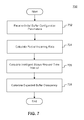
- FIG. 7 is a flowchart of an exemplary method 700 for determining expected buffer occupancy for buffer status reporting, consistent with some embodiments of the present disclosure.
- the exemplary method 700 may be implemented, for example, by the ISR module 401 of the base station.
- the method for determining expected buffer occupancy for buffer status reporting may include receiving initial buffer configuration parameters from a management application.
- the initial buffer configuration parameters may include, for example, the Incoming Packet Size Constant ⁇ .
- the method may further include calculating the Packet Incoming Rate (PIR).
- PIR Packet Incoming Rate
- the PIR may be determined by dividing the total number of packets received at the RLC entity corresponding to a UE's LCH by the time period within which the packets are received.
- the PIR may be updated by averaging the current PIR with the previous PIR based on the Incoming Packet Size Constant ⁇ .
- the method may include calculating the Intelligent Status Request Time Interval (ISRTI).
- the ISRTI may be calculated by the method described in connection with FIG. 6 .
- the method may further include calculating the expected buffer occupancy (EBO).
- the EBO may increase as the ISRTI or the PIR increases, and decrease as the ISRTI or the PIR decreases.
- the EBO may be combined with the CBO, and RLC entity may report a summation of the EBO and CBO to the MAC protocol layer in an internal control message, e.g., a MAC Status Request message.
- a computer-readable storage medium refers to any type of physical memory on which information or data readable by a processor may be stored.
- a computer-readable storage medium may store instructions for execution by one or more processors, including instructions for causing the processor(s) to perform steps or stages consistent with the embodiments described herein.
- the term “computer-readable medium” should be understood to include tangible items and exclude carrier waves and transient signals, i.e., be non-transitory. Examples include random access memory (RAM), read-only memory (ROM), volatile memory, nonvolatile memory, hard drives, CD ROMs, DVDs, flash drives, disks, and any other known physical storage media.
Abstract
Description
NumberOfPacketPerLCHPerUE=NumberOfPacketsReceivedFromPDCP/(current_time−previous_time) Step 1:
PIR=β*(current_NumberOfPacketPerLCHPerUE−previous_NumberOfPacketPerLCHPerUE)+(1−β)*Previous_PacketIncomingRate Step 2:
SITI=α*(current_time−previous_time)+(1×α)*Previous_SITI
ATO=
ISRTI=(SITI)*CBO/ATO Step 2:
CBO=CBO+IncomingPacketSize
ISRTI=(SITI)*CBO/ATO.
Claims (21)
Applications Claiming Priority (2)
| Application Number | Priority Date | Filing Date | Title |
|---|---|---|---|
| IN1217/CHE/2014 | 2014-03-10 | ||
| IN1217CH2014 | 2014-03-10 |
Publications (2)
| Publication Number | Publication Date |
|---|---|
| US20150257033A1 US20150257033A1 (en) | 2015-09-10 |
| US9179357B2 true US9179357B2 (en) | 2015-11-03 |
Family
ID=54018794
Family Applications (1)
| Application Number | Title | Priority Date | Filing Date |
|---|---|---|---|
| US14/258,579 Active 2034-07-04 US9179357B2 (en) | 2014-03-10 | 2014-04-22 | Systems and methods for buffer status reporting in wireless communication systems |
Country Status (1)
| Country | Link |
|---|---|
| US (1) | US9179357B2 (en) |
Cited By (2)
| Publication number | Priority date | Publication date | Assignee | Title |
|---|---|---|---|---|
| US20170019229A1 (en) * | 2015-07-17 | 2017-01-19 | Makoto Torikoshi | Communication apparatus, power control method, and recording medium |
| US11425592B2 (en) * | 2017-09-12 | 2022-08-23 | Nokia Solutions And Networks Oy | Packet latency reduction in mobile radio access networks |
Families Citing this family (2)
| Publication number | Priority date | Publication date | Assignee | Title |
|---|---|---|---|---|
| US10645610B2 (en) * | 2017-11-24 | 2020-05-05 | Mediatek Singapore Pte. Ltd. | Method and apparatus for skipping uplink transmission in mobile communications |
| US11190456B2 (en) * | 2018-11-30 | 2021-11-30 | International Business Machines Corporation | Real-time adjustment of packet size limit in virtual networks |
Citations (13)
| Publication number | Priority date | Publication date | Assignee | Title |
|---|---|---|---|---|
| US20030145097A1 (en) | 2002-01-28 | 2003-07-31 | Connor Patrick L. | Ingress throttling via adaptive interrupt delay scheduling |
| WO2003090419A1 (en) | 2002-04-18 | 2003-10-30 | Motorola, Inc., | Reducing packet data delay variation |
| US20070127373A1 (en) | 2005-10-03 | 2007-06-07 | Texas Instruments Incorporated | Delayed Data Feeding for Increased Media Access Control Processing Time |
| US20080294793A1 (en) | 2004-05-27 | 2008-11-27 | Microsoft Corporation | Reducing information reception delays |
| US20090119564A1 (en) | 2007-11-02 | 2009-05-07 | Telefonaktiebolaget Lm Ericsson (Publ) | Methods and Apparatus for Processing Error Control Messages in a Wireless Communication System |
| US20090215456A1 (en) | 2008-02-01 | 2009-08-27 | Lg Electronics Inc. | Method for sending rlc pdu and allocating radio resource in mobile communications system and rlc entity of mobile communications |
| US20100074230A1 (en) * | 2007-03-06 | 2010-03-25 | Ntt Docomo, Inc. | Mobile station, base station, radio communication system, and communication control method |
| US20100165936A1 (en) | 2008-12-22 | 2010-07-01 | Qualcomm Incorporated | PRE-BUNDLING OF RLC SDUs IN THE RLC LAYER |
| US20110299476A1 (en) * | 2007-08-12 | 2011-12-08 | Patrick Fischer | Wireless device and method of transmitting uplink data and buffer status reports in a wireless communications system |
| US20130272123A1 (en) * | 2010-08-17 | 2013-10-17 | Qualcomm Incorporated | Systems and Methods for Traffic Policing |
| US8913518B2 (en) * | 2012-08-03 | 2014-12-16 | Intel Corporation | Enhanced node B, user equipment and methods for discontinuous reception in inter-ENB carrier aggregation |
| US20150071260A1 (en) * | 2011-09-23 | 2015-03-12 | Lg Electronics Inc. | Method and apparatus for transmitting and receiving signal to and from network at user equipment in a wireless communication system |
| US9019818B2 (en) * | 2010-04-02 | 2015-04-28 | Nokia Solutions And Networks Oy | Dynamic buffer status report selection for carrier aggregation |
-
2014
- 2014-04-22 US US14/258,579 patent/US9179357B2/en active Active
Patent Citations (13)
| Publication number | Priority date | Publication date | Assignee | Title |
|---|---|---|---|---|
| US20030145097A1 (en) | 2002-01-28 | 2003-07-31 | Connor Patrick L. | Ingress throttling via adaptive interrupt delay scheduling |
| WO2003090419A1 (en) | 2002-04-18 | 2003-10-30 | Motorola, Inc., | Reducing packet data delay variation |
| US20080294793A1 (en) | 2004-05-27 | 2008-11-27 | Microsoft Corporation | Reducing information reception delays |
| US20070127373A1 (en) | 2005-10-03 | 2007-06-07 | Texas Instruments Incorporated | Delayed Data Feeding for Increased Media Access Control Processing Time |
| US20100074230A1 (en) * | 2007-03-06 | 2010-03-25 | Ntt Docomo, Inc. | Mobile station, base station, radio communication system, and communication control method |
| US20110299476A1 (en) * | 2007-08-12 | 2011-12-08 | Patrick Fischer | Wireless device and method of transmitting uplink data and buffer status reports in a wireless communications system |
| US20090119564A1 (en) | 2007-11-02 | 2009-05-07 | Telefonaktiebolaget Lm Ericsson (Publ) | Methods and Apparatus for Processing Error Control Messages in a Wireless Communication System |
| US20090215456A1 (en) | 2008-02-01 | 2009-08-27 | Lg Electronics Inc. | Method for sending rlc pdu and allocating radio resource in mobile communications system and rlc entity of mobile communications |
| US20100165936A1 (en) | 2008-12-22 | 2010-07-01 | Qualcomm Incorporated | PRE-BUNDLING OF RLC SDUs IN THE RLC LAYER |
| US9019818B2 (en) * | 2010-04-02 | 2015-04-28 | Nokia Solutions And Networks Oy | Dynamic buffer status report selection for carrier aggregation |
| US20130272123A1 (en) * | 2010-08-17 | 2013-10-17 | Qualcomm Incorporated | Systems and Methods for Traffic Policing |
| US20150071260A1 (en) * | 2011-09-23 | 2015-03-12 | Lg Electronics Inc. | Method and apparatus for transmitting and receiving signal to and from network at user equipment in a wireless communication system |
| US8913518B2 (en) * | 2012-08-03 | 2014-12-16 | Intel Corporation | Enhanced node B, user equipment and methods for discontinuous reception in inter-ENB carrier aggregation |
Non-Patent Citations (5)
Cited By (3)
| Publication number | Priority date | Publication date | Assignee | Title |
|---|---|---|---|---|
| US20170019229A1 (en) * | 2015-07-17 | 2017-01-19 | Makoto Torikoshi | Communication apparatus, power control method, and recording medium |
| US10051562B2 (en) * | 2015-07-17 | 2018-08-14 | Ricoh Company, Ltd. | Communication apparatus, power control method, and recording medium |
| US11425592B2 (en) * | 2017-09-12 | 2022-08-23 | Nokia Solutions And Networks Oy | Packet latency reduction in mobile radio access networks |
Also Published As
| Publication number | Publication date |
|---|---|
| US20150257033A1 (en) | 2015-09-10 |
Similar Documents
| Publication | Publication Date | Title |
|---|---|---|
| US11116029B2 (en) | Mobility management entity, network entity, and method and computer readable medium therefor | |
| JP5897116B2 (en) | Mobile transceiver, base station transceiver, data server, and related apparatus, method and computer program | |
| US8630202B2 (en) | Method and apparatus for controlling buffer status report messaging | |
| EP3219106B1 (en) | Context-aware resource management for video streaming services | |
| US11026133B2 (en) | Flexible quality of service for inter-base station handovers within wireless network | |
| EP4013108A1 (en) | User plane information reporting method and apparatus | |
| US9787595B2 (en) | Evolved node-B and mobility management entity and user equipment and methods for supporting attended and unattended services | |
| US10341991B2 (en) | Dynamic uplink/downlink subframe configuration | |
| US20140200011A1 (en) | LTE/HSDPA Carrier Aggregation | |
| US20210385723A1 (en) | Policy Management Method and Apparatus | |
| US20220159504A1 (en) | Method and apparatus for adjusting qos of a qos flow based on assistance information | |
| US9179357B2 (en) | Systems and methods for buffer status reporting in wireless communication systems | |
| US20170150403A1 (en) | Methods and nodes for managing bearers | |
| US20240121666A1 (en) | Method and apparatus for flow control | |
| US9609543B1 (en) | Determining a transmission order of data packets in a wireless communication system | |
| US11647419B2 (en) | Adjusting window size based on quality of experience | |
| EP2624625A1 (en) | Gateway data transmission method, device and system | |
| US9246817B1 (en) | System and method of managing traffic flow in a communication network | |
| WO2017107926A1 (en) | Method, device and system for distributing data in mobile network | |
| US10313918B2 (en) | Management of received internet protocol packet bundling for real time services | |
| WO2024032211A1 (en) | Congestion control method and apparatus | |
| US20240114384A1 (en) | Information transmission method and apparatus, communication device, and storage medium | |
| WO2023197143A1 (en) | Base station, user equipment, and extended reality processing method | |
| KR102161014B1 (en) | Method and apparatus for scheduling of packet |
Legal Events
| Date | Code | Title | Description |
|---|---|---|---|
| AS | Assignment |
Owner name: WIPRO LIMITED, INDIA Free format text: ASSIGNMENT OF ASSIGNORS INTEREST;ASSIGNORS:MANNA, AVIJIT;CHAUDHURI, SAPTARSHI;SIGNING DATES FROM 20140224 TO 20140307;REEL/FRAME:032728/0988 |
|
| FEPP | Fee payment procedure |
Free format text: PAYER NUMBER DE-ASSIGNED (ORIGINAL EVENT CODE: RMPN); ENTITY STATUS OF PATENT OWNER: LARGE ENTITY Free format text: PAYOR NUMBER ASSIGNED (ORIGINAL EVENT CODE: ASPN); ENTITY STATUS OF PATENT OWNER: LARGE ENTITY |
|
| STCF | Information on status: patent grant |
Free format text: PATENTED CASE |
|
| CC | Certificate of correction | ||
| MAFP | Maintenance fee payment |
Free format text: PAYMENT OF MAINTENANCE FEE, 4TH YEAR, LARGE ENTITY (ORIGINAL EVENT CODE: M1551); ENTITY STATUS OF PATENT OWNER: LARGE ENTITY Year of fee payment: 4 |
|
| MAFP | Maintenance fee payment |
Free format text: PAYMENT OF MAINTENANCE FEE, 8TH YEAR, LARGE ENTITY (ORIGINAL EVENT CODE: M1552); ENTITY STATUS OF PATENT OWNER: LARGE ENTITY Year of fee payment: 8 |