US9179394B2 - Apparatus and method for coordinated sensing of wireless devices in a communication system - Google Patents
Apparatus and method for coordinated sensing of wireless devices in a communication system Download PDFInfo
- Publication number
- US9179394B2 US9179394B2 US11/974,119 US97411907A US9179394B2 US 9179394 B2 US9179394 B2 US 9179394B2 US 97411907 A US97411907 A US 97411907A US 9179394 B2 US9179394 B2 US 9179394B2
- Authority
- US
- United States
- Prior art keywords
- base station
- quiet periods
- quiet
- sensing
- wireless devices
- Prior art date
- Legal status (The legal status is an assumption and is not a legal conclusion. Google has not performed a legal analysis and makes no representation as to the accuracy of the status listed.)
- Active, expires
Links
Images


Classifications
-
- H—ELECTRICITY
- H04—ELECTRIC COMMUNICATION TECHNIQUE
- H04W—WIRELESS COMMUNICATION NETWORKS
- H04W48/00—Access restriction; Network selection; Access point selection
- H04W48/08—Access restriction or access information delivery, e.g. discovery data delivery
- H04W48/12—Access restriction or access information delivery, e.g. discovery data delivery using downlink control channel
Definitions
- This disclosure is generally directed to communication systems and more specifically to an apparatus and method for coordinated sensing of wireless devices in a communication system.
- wireless communication systems include base stations or access points in wireless local area networks (WLANs).
- the base stations or access points typically include components for wirelessly transmitting and receiving information.
- the base stations or access points typically interact with wireless devices (such as mobile telephones and computing devices) to provide wireless services (such as wireless voice and data services) to the wireless devices.
- wireless devices such as mobile telephones and computing devices
- wireless services such as wireless voice and data services
- the base stations or access points “overlap,” which means that multiple base stations or access points have overlapping coverage areas and can provide service to the same physical area.
- the phrase “base station” and its derivatives may be used to collectively refer to base stations, access points, and other similar structures.
- Wi-Fi networks routinely engage in various sensing activities to identify sources of interference that can interrupt or degrade wireless communications.
- base stations often need to engage in “incumbent user” sensing.
- the base stations may represent transmitters having a lower priority or right to use a particular wireless frequency or frequency channel.
- Other devices called “incumbent users” typically represent transmitters having a higher priority or right to use a particular wireless frequency or frequency channel.
- a television broadcaster may represent an incumbent user having a higher priority to use a particular wireless frequency or frequency channel.
- the base stations in these or other types of networks often need to sense whether they are or could be interfering with an incumbent user. This may involve simply detecting the presence of an incumbent user that could experience interference due to the operation of one or more of the base stations. If an incumbent user having a higher priority to a frequency or frequency channel is detected, a base station could take suitable corrective action. For instance, the base station could change the wireless frequency or frequency channel it uses to communicate with wireless devices in the network. Also, the base stations may engage in incumbent user sensing to determine if a particular wireless frequency or frequency channel is currently available for use by the base stations (i.e. no incumbent users are detected on a particular wireless frequency or frequency channel).
- This disclosure provides an apparatus and method for coordinated sensing of wireless devices in a communication system.
- a method in a first embodiment, includes identifying one or more first quiet periods associated with a first base station and identifying one or more second quiet periods associated with a second base station. The method also includes determining whether an amount of overlap between the first and second quiet periods is acceptable. In addition, the method includes using the first and second quiet periods to sense wireless devices when the amount of overlap between the first and second quiet periods is acceptable.
- the amount of overlap is acceptable only when no overlap exists between the first and second quiet periods.
- the first base station is associated with a first decision time related to the one or more first quiet periods
- the second base station is associated with a second decision time related to the one or more second quiet periods.
- the method also includes determining whether the first decision time is earlier than the second decision time when the amount of overlap between the first and second quiet periods is not acceptable.
- the information associated with the one or more first quiet periods may be rebroadcast from the first base station (the information having been broadcast earlier).
- the first decision time is later than the second decision time, one or more new first quiet periods associated with the first base station may be identified, and information associated with the one or more new first quiet periods may be broadcast from the first base station.
- a coordinate device is served by the first base station and assists the second base station.
- the method also includes selecting the coordinate device from among a plurality of devices. The coordinate device is selected based on the coordinate device being located in a coverage area served by both the first and second base stations and away from an interference contour associated with the second base station.
- a coordinate device is served by the first base station and assists the second base station.
- the method further includes setting a detection distance of the coordinate device. The detection distance is set so that a detection area associated with the coordinate device is substantially within an interference contour associated with the second base station.
- an apparatus in a second embodiment, includes a memory configured to store information identifying one or more first quiet periods associated with a first base station and information identifying one or more second quiet periods associated with a second base station.
- the apparatus also includes a controller configured to determine whether an amount of overlap between the first and second quiet periods is acceptable and to initiate sensing of wireless devices using the first and second quiet periods when the amount of overlap between the first and second quiet periods is acceptable.
- a computer program is embodied on a computer readable medium.
- the computer program includes computer readable program code for identifying one or more first quiet periods associated with a first base station and identifying one or more second quiet periods associated with a second base station.
- the computer program also includes computer readable program code for determining whether an amount of overlap between the first and second quiet periods is acceptable.
- the computer program further includes computer readable program code for initiating sensing of wireless devices using the first and second quiet periods when the amount of overlap between the first and second quiet periods is acceptable.
- an apparatus in a fourth embodiment, includes a transceiver configured to communicate wirelessly with a first base station.
- the apparatus also includes a controller configured to perform (i) in-band sensing of wireless devices during one or more first quiet periods associated with the first base station and (ii) out-band sensing of wireless devices during one or more second quiet periods associated with a second base station.
- the first and second quiet periods represent non-overlapping quiet periods.
- FIG. 1 illustrates an example communication system according to this disclosure
- FIG. 2 illustrates an example distributive quiet period sensing in a communication system according to this disclosure
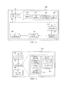
- FIG. 3 illustrates an example base station according to this disclosure
- FIG. 4 illustrates an example customer premises equipment (CPE) according to this disclosure
- FIG. 5 illustrates an example method for selecting non-overlapping quiet periods in a communication system according to this disclosure
- FIG. 6 illustrates an example method for sensing incumbent users during non-overlapping quiet periods in a communication system according to this disclosure.
- FIG. 7 illustrates an example technique for false detection avoidance in a communication system according to this disclosure.
- FIGS. 1 through 7 discussed below, and the various embodiments used to describe the principles of the present invention in this patent document are by way of illustration only and should not be construed in any way to limit the scope of the invention. Those skilled in the art will understand that the principles of the invention may be implemented in any type of suitably arranged device or system.
- FIG. 1 illustrates an example communication system 100 according to this disclosure.
- the embodiment of the system 100 shown in FIG. 1 is for illustration only. Other embodiments of the system 100 could be used without departing from the scope of this disclosure.
- the system 100 includes multiple cell sites 102 a - 102 c .
- the cell sites 102 a - 102 c generally include areas where one or more wireless devices may receive wireless service.
- the cell sites 102 a - 102 c may include areas where wireless devices may receive wireless voice and data services.
- each of the cell sites 102 a - 102 c is associated with a different wireless frequency or frequency channel.
- the dashed line around each of the cell sites 102 a - 102 c may represent an interference contour, which defines the area in which a cell site may cause interference on the wireless frequency or frequency channel used by the cell site. While shown as being circular in FIG. 1 , each of the cell sites 102 a - 102 c may have any suitable interference contour.
- the cell sites 102 a - 102 c include base stations 104 a - 104 c , respectively.
- Each of the base stations 104 a - 104 c communicates with one or more wireless devices over a wireless medium, such as by using radio frequency (RF) or other wireless technology.
- RF radio frequency
- the base stations 104 a - 104 c may transmit and receive wireless signals containing voice, data, and/or control signals to and from the wireless devices.
- each of the base stations 104 a - 104 c communicates using a different wireless frequency or frequency channel compared to its neighboring base station(s).
- Each of the base stations 104 a - 104 c includes any suitable structure for communicating wirelessly with one or more wireless devices, including cellular base stations and wireless access points.
- a base station is shown in FIG. 3 , which is described below.
- the base stations 104 a - 104 c reside at the centers of the cell sites 102 a - 102 c
- each of the base stations 104 a - 104 c could reside at any suitable position within its cell site.
- the base stations 104 a - 104 c communicate with customer premises equipment (CPEs) 106 a - 106 c located within the cell sites 102 a - 102 c .
- CPEs customer premises equipment
- Each of the CPEs 106 a - 106 c represents one or more components that provide communication services to a customer.
- the CPEs 106 a - 106 c could include telephones, modems, set-top boxes, computing devices, or any other or additional components that may receive voice, data, or other services in the system 100 .
- the CPEs 106 a - 106 c could include fixed or mobile devices.
- Each of the CPEs 106 a - 106 c includes any suitable structure for receiving wireless communication services.
- FIG. 4 One example embodiment of a CPE is shown in FIG. 4 , which is described below.
- the base stations 104 a - 104 c and the CPEs 106 a - 106 c may use any suitable wireless technology.
- the base stations 104 a - 104 c and the CPEs 106 a - 106 c may use radio frequency (RF) signals to communicate.
- RF radio frequency
- the base stations 104 a - 104 c and the CPEs 106 a - 106 c may support the IEEE 802.16, 802.22, or other standard(s) for wireless communications.
- An incumbent transmitter (ITx) 108 is shown as residing within the cell sites 102 a and 102 c .
- the incumbent transmitter 108 generally represents a transmitting device that has a higher priority to use a wireless frequency or frequency channel in at least one of the cell sites, such as in the cell site 102 a (but not necessarily in the cell site 102 c ).
- the incumbent transmitter 108 could, for example, represent a television station transmitter or other incumbent user devices.
- various components in the system 100 perform sensing operations to detect incumbent users (such as the incumbent transmitter 108 ) or to find available frequencies or channels.
- the base stations 104 a - 104 c and/or the CPEs 106 a - 106 c may perform “in-band” sensing.
- “In-band” sensing generally refers to sensing or detecting devices that are transmitting on the same frequency or frequency channel as the sensing device.
- the base stations 104 a - 104 c and/or the CPEs 106 a - 106 c may perform “out-band” sensing.
- “Out-band” sensing generally refers to sensing or detecting devices that are transmitting on a different frequency or frequency channel as the sensing device.
- the CPEs 106 a - 106 c that perform “out-band” sensing may be referred to as “coordinate CPEs” or “non-coordinate CPEs.”
- a “non-coordinate CPE” generally refers to a CPE that performs “out-band” sensing only on behalf of its serving base station (the base station actually providing service to the CPE).
- a “coordinate CPE” generally refers to a CPE that performs “out-band” sensing on behalf of its serving base station and at least one assisted base station (a base station not actually providing service to the CPE). Each “coordinate CPE” typically resides (at least temporarily) in an overlapped area that is served by at least two of the base stations 104 a - 104 c .
- the CPE 106 a could be associated with the base station 104 a and represent a coordinate CPE for the base stations 104 b - 104 c
- the CPE 106 b could be associated with the base station 104 b and represent a coordinate CPE for the base stations 104 a and 104 c
- the CPE 106 c could be associated with the base station 104 c and represent a coordinate CPE for the base stations 104 a - 104 b .
- the phrases “assisted cell site” and “assisted base station” refer to a cell site and a base station, respectively, that are helped by a coordinate CPE served by a different cell site or base station, where the coordinate CPE performs or assists in “out-band” sensing for the assisted cell site or base station.
- the CPE 106 c could be served by the cell site 102 c and perform “out-band” sensing for the cell site 102 a , making the cell site 102 a an “assisted” cell site.
- the “in-band” and “out-band” sensing allow the base stations 104 a - 104 c to identify incumbent users and make modifications to their operations as necessary (such as by switching frequency channels).
- the “out-band” sensing also allows the base stations 104 a - 104 c to identify frequencies or channels that are potentially available for use (such as channels where no incumbent users are detected).
- quiet periods of the base stations 104 a - 104 c can be coordinated.
- a quiet period generally represents a period of time when a base station and its associated wireless devices stop transmitting on a particular frequency or frequency channel.
- the quiet periods of a first base station may allow that first base station (or its associated CPEs) to perform “in-band” sensing operations in their working channels. Also, the quiet periods of other base stations may allow the first base station (or its associated coordinate CPEs) to perform “out-band” sensing operations in their working channels.
- the quiet periods of the base stations 104 a - 104 c may be coordinated so that they do not overlap with one another (or so that any amount of overlap is acceptable).
- the base station 104 a and its associated CPE 106 a may stop transmitting on its working frequency or frequency channel.
- “in-band” sensing may occur, and the base station 104 a and/or the CPE 106 a may “listen” to this frequency or frequency channel and attempt to detect any incumbent users.
- the base station 104 a or the CPE 106 a could attempt to determine whether any incumbent users are transmitting on the same frequency or frequency channel as the base station 104 a . If so, the base station 104 a could change its frequency or frequency channel (and, if necessary, the CPE 106 a could notify the base station 104 a of the interference).
- each of the base stations 104 b - 104 c and its respective wireless devices may stop transmitting on its respective frequency or frequency channel.
- “out-band” sensing may occur, and the coordinate CPE 106 a may “listen” to these frequencies or frequency channels and attempt to detect any incumbent users. For instance, the coordinate CPE 106 a could attempt to determine whether any incumbent users are transmitting on the same frequency or frequency channel as any of the other base stations 104 b - 104 c . If so, the coordinate CPE 106 a notifies its base station 104 a , and the base station 104 a may then notify the other base station 104 b or 104 c.
- the coordinate CPEs may (among other things) help to identify “hidden” incumbent users.
- a “hidden” incumbent user generally represents a device operating within a cell site that is not detectable by the base station in that cell site or its associated CPEs.
- the incumbent transmitter 108 may be located far away from the base station 104 a and the CPE 106 a served by the base station 104 a in the cell site 102 a .
- the base station 104 a and the CPE 106 a may be unable to detect the incumbent transmitter 108 .
- the coordinate CPE 106 c may be located much closer to the incumbent transmitter 108 .
- the coordinate CPE 106 c could perform “out-band” sensing and detect the incumbent transmitter 108 operating on the same frequency channel as the base station 104 a . Because the incumbent transmitter 108 resides within the interference contour of the cell site 102 a , the incumbent transmitter 108 could be interfered with by the base station 104 a . As a result, the coordinate CPE 106 c notifies its serving base station (base station 104 c in this example) of the interference or the existence of the incumbent transmitter 108 .
- the base station 104 c then notifies the base station 104 a of the interference or the existence of the incumbent transmitter 108 (either directly or indirectly, such as through a backhaul IP network or a mobile switching center or other component controlling or communicating with the base stations 104 a - 104 c ).
- the base station 104 a may change its operation, such as by selecting a new frequency or frequency channel, even though the base station 104 a and its associated CPE 106 a could not or did not detect the presence of the incumbent transmitter 108 .
- FIG. 1 illustrates one example of a communication system 100
- the system 100 could include any number of cell sites, base stations, CPEs (whether coordinate or non-coordinate), and incumbent users.
- the system 100 could be connected to any suitable network(s), such as another wireless network or a data network.
- FIG. 1 illustrates one example operational environment in which base stations may coordinate their quiet periods. This functionality could be used in any other communication system.
- FIG. 2 illustrates an example distributive quiet period sensing 200 in a communication system according to this disclosure.
- the distributive quiet period sensing 200 shown in FIG. 2 is for illustration only. Other distributive quiet periods could be used during sensing without departing from the scope of this disclosure. Also, for ease of explanation, the distributive quiet period sensing 200 of FIG. 2 is described with respect to the system 100 of FIG. 1 . The distributive quiet period sensing 200 of FIG. 2 could be used with any other suitable system.
- the distributive quiet period sensing 200 involves three different frequency channels labeled “Ch. 1,” “Ch. 2,” and “Ch. 3.” These three channels could, for example, be associated with the three base stations 104 a - 104 c in FIG. 1 . Each of the channels is generally associated with a different frequency or frequency range. Each of the channels is also associated with multiple transmit periods 202 a - 202 c . These transmit periods 202 a - 202 c denote periods of time when the channels are in use by the base stations 104 a - 104 c and their associated wireless devices, such as when the base stations 104 a - 104 c and their associated wireless devices are transmitting wireless signals on their associated working frequency channels.
- Each of the channels is further associated with multiple quiet periods 204 a - 204 c .
- These quiet periods 204 a - 204 c denote periods of time when the channels are not in use by the base stations 104 a - 104 c and their associated wireless devices, meaning periods of time when the base stations 104 a - 104 c and their associated wireless devices are not transmitting wireless signals on their associated frequency channels.
- the curved lines that appear within each channel's quiet periods represent “in-band” sensing that occurs during those quiet periods.
- “in-band” sensing may occur during each quiet period 204 a in “Channel 1,” and the base station 104 a and/or its associated CPE 106 a may listen to “Channel 1” and attempt to identify any incumbent users on “Channel 1.”
- “in-band” sensing may occur during each quiet period 204 b in “Channel 2,” and the base station 104 b and/or its associated CPE 106 b may listen to “Channel 2” and attempt to identify any incumbent users on “Channel 2.”
- Similar operations may occur during the quiet periods 204 c in “Channel 3.”
- the length of each quiet period 204 a - 204 c is selected to be the minimal amount of time necessary to sense in-band communications. This minimal amount of time may help to reduce the impact of the quiet periods 204 a - 204 c on
- the straight lines that occur between channels in FIG. 2 represent “out-band” sensing that occurs.
- “out-band” sensing may be performed by the coordinate CPEs 106 b - 106 c (which normally operate using “Channel 2” and “Channel 3,” respectively) during each quiet period 204 a in “Channel 1.” This allows the coordinate CPEs 106 b - 106 c to detect incumbent users operating on the same frequency channel as the base station 104 a .
- “out-band” sensing may be performed by the coordinate CPEs 106 a and 106 c (which normally operate using “Channel 1” and “Channel 3,” respectively) during each quiet period 204 b in “Channel 2.”
- “out-band” sensing may be performed by the coordinate CPEs 106 a - 106 b (which normally operate using “Channel 1” and “Channel 2,” respectively) during each quiet period 204 c in “Channel 3.”
- the coordinate CPE may inform its serving base station, which may then notify the appropriate assisted base station (the base station in the cell site using the same frequency or channel as the incumbent user).
- the system 100 may operate more effectively or efficiently in identifying incumbent users. If the quiet periods 204 a - 204 c were completely synchronized (all quiet periods start and stop at the same times), the base stations 104 a - 104 c and their associated CPEs 106 a - 106 c could perform “in-band” sensing during the synchronized quiet periods 204 a - 204 c . However, the coordinate CPEs 106 a - 106 c may be unable to perform “out-band” sensing during any of the quiet periods 204 a - 204 c for their assisted base stations.
- a coordinate CPE can perform “in-band” sensing during the quiet periods of its serving base station and “out-band” sensing for its assisted base station(s) during the quiet periods of the assisted base station(s).
- FIG. 2 illustrates one example of a distributive quiet period sensing 200 in a communication system
- various changes may be made to FIG. 2 .
- the use of three channels is for illustration only, and any other suitable number of channels can be involved in the quiet period coordination.
- the exact placement of the quiet periods 204 a - 204 c in FIG. 2 is for illustration only, and the quiet periods could be arranged in any suitable non-overlapping manner.
- two quiet periods may be “non-overlapping” even when one quiet period ends and another quiet period begins at the same time.
- a small amount of overlap could be allowed between two quiet periods in two different frequencies or channels.
- the quiet periods may or may not have constant time periods, and the length between quiet periods may or may not be constant.
- FIG. 3 illustrates an example base station 104 a according to this disclosure.
- the embodiment of the base station 104 a shown in FIG. 3 is for illustration only. Other embodiments of the base station 104 a could be used without departing from the scope of this disclosure. Also, for ease of explanation, the base station 104 a of FIG. 3 is described with respect to the system 100 of FIG. 1 . The base station 104 a of FIG. 3 could be used with any other suitable system.
- the base station 104 a includes a base station controller 302 and one or more base transceiver subsystems 304 .
- the base station controller 302 generally controls the overall operation of the base station 104 a .
- the base station controller 302 could, for example, control wireless communication resources in the base station 104 a , such as the base transceiver subsystems 304 .
- the base station controller 302 includes any hardware, software, firmware, or combination thereof for controlling a base station.
- Each base transceiver subsystem 304 generally includes components used for wireless communications to and from the base station 104 a .
- each base transceiver subsystem 304 includes a base transceiver subsystem (BTS) controller 306 , a channel controller 308 , a transceiver interface 310 , a transceiver 312 , and an antenna 314 .
- the BTS controller 306 generally controls the base transceiver subsystem 304 and communicates with the base station controller 302 .
- the BTS controller 306 includes any hardware, software, firmware, or combination thereof for controlling a base transceiver subsystem.
- the channel controller 308 generally controls communication channels for communicating with wireless devices, such as forward (outbound) and reverse (inbound) channels.
- the channel controller 308 includes any hardware, software, firmware, or combination thereof for controlling communication channels in a base transceiver subsystem.
- the transceiver interface 310 acts as an interface between the communication channels and the transceiver 312 .
- the transceiver interface 310 includes any suitable structure providing an interface to a transceiver.
- the transceiver 312 includes any suitable structure supporting wireless transmission of outbound signals and wireless reception of inbound signals, such as an RF transceiver.
- the transceiver 312 could include amplifiers, filters, and analog-to-digital converters for processing inbound signals and amplifiers, filters, and digital-to-analog converters for processing outbound signals.
- the antenna 314 represents any suitable structure for transmitting and receiving wireless signals, such as an RF antenna or antenna array.
- the base station controller 302 includes or supports various components or functions for the coordination of quiet periods with other base stations (such as base stations 104 b - 104 c in FIG. 1 ). Also, the base station controller 302 includes or supports various components or functions for controlling “in-band” and “out-band” sensing by CPEs associated with the base station 104 a (such as CPE 106 a in FIG. 1 ). For example, the base station controller 302 includes or has access to a memory 316 , which can be used to store instructions or data used, generated, or collected by the base station controller 302 .
- the memory 316 could be used to store information associated with the quiet periods used by the base station 104 a and information associated with the quiet periods used by other base stations 104 b - 104 c .
- the memory 316 could also be used to store information associated with one or more coordinate CPEs currently supporting other assisted base stations, such as an identity and location of a coordinate CPE.
- the memory 316 could store any other or additional information.
- the memory 316 includes any suitable volatile and/or non-volatile storage and retrieval device or devices.
- the base station controller 302 also includes or has access to a CPE manager 318 .
- the CPE manager 318 supports interaction with various CPEs by the base station controller 302 .
- the CPE manager 318 could initiate the collection of various information, such as location information, from the CPEs.
- the CPE manager 318 could also initiate incumbent user sensing by the CPEs by initiating “in-band” and/or “out-band” sensing by its associated CPEs via the appropriate command(s).
- the CPE manager 318 could further initiate “out-band” sensing by coordinate CPEs for other (assisted) base stations during the assisted base stations' quiet periods via the appropriate command(s).
- the CPE manager 318 could send a channel sensing command to a CPE, where the channel sensing command identifies when sensing is to occur, the channel on which sensing is to occur, and a sensing contour (the range at which sensing is to occur).
- the same or similar commands could be used for “in-band” sensing, “out-band” sensing for the serving base station, and “out-band” sensing for an assisted base station.
- the CPE manager 318 could further initiate reporting of the results of the incumbent user sensing by the CPEs via the appropriate command(s).
- the results could represent any suitable information, such as an identification of all incumbent users sensed and the frequency or channel used by each sensed incumbent user.
- the CPE manager 318 includes any hardware, software, firmware, or combination thereof for interacting with and controlling one or more CPEs.
- the base station controller 302 further includes or has access to a coordinate CPE selector 320 .
- the coordinate CPE selector 320 allows the base station controller 302 to select one or more of its associated CPEs for use as coordinate CPEs. For example, each associated CPE being served by the base station 104 a could report its position to that base station 104 a . Also, the base station 104 a could be provided with an interfering contour associated with a neighboring base station 104 b or 104 c .
- the interfering contour generally defines the area where two base stations' coverage areas overlaps.
- the coordinate CPE selector 320 can use the reported positions of the CPEs and the interfering contour of each assisted base station 104 b or 104 c to select coordinate CPEs, which can be used (among other things) to perform “in-band” and/or “out-band” sensing for the serving base station 104 a and “out-band” sensing for the assisted base station 104 b or 104 c .
- the coordinate CPE selector 320 could identify one or more of its associated CPEs that reside within the area where two base stations' coverage areas overlap, and the coordinate CPE selector 320 could use at least one of those CPEs as a coordinate CPE.
- the coordinate CPE selector 320 includes any hardware, software, firmware, or combination thereof for identifying or selecting coordinate CPES.
- the base station controller 302 includes or has access to a quiet period (QP) selector 322 .
- the quiet period selector 322 operates to select quiet periods that can be used by the base station 104 a to support “in-band” and “out-band” sensing.
- the quiet period selector 322 could, for example, identify a quiet period start time and a quiet period length for the base station 104 a , and then compare that information to the quiet period start times and quiet period lengths of other base stations 104 b - 104 c . If overlap is not detected in the quiet periods, the base station 104 a may use the quiet period start time and the quiet period length identified by the quiet period selector 322 .
- the quiet period selector 322 can take steps to ensure that the quiet periods used by the base station 104 a do not overlap with other quiet periods of other base stations 104 b - 104 c .
- the quiet period selector 322 could also determine whether an amount of overlap between the quiet periods is acceptable, such as whether the amount of overlap exceeds an acceptable threshold.
- the quiet period selector 322 includes any hardware, software, firmware, or combination thereof for identifying a quiet period for a base station.
- FIG. 3 illustrates one example of a base station 104 a
- the functional division shown in FIG. 3 is for illustration only.
- Various components in FIG. 3 could be combined or omitted and additional components could be added according to particular needs.
- the components 318 - 322 of the base station could reside on the memory 316 (such as when they represent software or firmware).
- various components or functions shown as residing within the base station 104 a could reside in other components, such as within a coordinate CPE 106 a .
- FIG. 3 illustrates one example base station capable of coordinating its quiet periods with other base stations. This functionality could be used in any other device.
- FIG. 4 illustrates an example CPE 106 a in accordance with this disclosure.
- the embodiment of the CPE 106 a shown in FIG. 4 is for illustration only. Other embodiments of the CPE 106 a could be used without departing from the scope of this disclosure. Also, for ease of explanation, the CPE 106 a of FIG. 4 is described with respect to the system 100 of FIG. 1 . The CPE 106 a of FIG. 4 could be used with any other suitable system.
- the CPE 106 a includes a CPE controller 402 and a CPE operation module 404 .
- the CPE controller 402 generally controls the overall operation of the CPE 106 a .
- the CPE controller 402 could, for example, control wireless communications with a base station, such as base station 104 a .
- the CPE controller 402 could also support the collection of various information during “in-band” and “out-band” sensing for its serving base station.
- the CPE controller 402 could support the collection of various information during “out-band” sensing for an assisted base station.
- the CPE controller 402 includes any hardware, software, firmware, or combination thereof for controlling a CPE.
- the CPE operation module 404 performs various operations associated with the CPE 106 a .
- the CPE operation module 404 could interface and interact with telephones, fax machines, and computing devices in a residence or other location, allowing the devices to receive communication services via the CPE 106 a .
- the CPE operation module 404 could perform any of a wide variety of functions, depending on the particular implementation and purpose of the CPE 106 a.
- a transceiver 406 and an antenna 408 facilitate wireless communications between the CPE 106 a and, for example, the base station 104 a .
- the transceiver 406 and the antenna 408 may also facilitate wireless detection of incumbent users operating within range of the CPE 106 a .
- the transceiver 406 includes any suitable structure supporting wireless transmission of outbound signals and wireless reception of inbound signals, such as an RF transceiver.
- the antenna 408 represents any suitable structure for transmitting and receiving wireless signals, such as an RF antenna or antenna array.
- the CPE controller 402 includes or supports various components or functions for “in-band” and “out-band” sensing on behalf of its serving base station (such as base station 104 a ) and “out-band” sensing on behalf of an assisted base station (such as base station 104 b or 104 c ).
- the CPE controller 402 includes or has access to a sensing manager 410 .
- the sensing manager 410 can perform coordinate sensing, which may allow the sensing manager 410 to determine the location of the CPE 106 a .
- the sensing manager 410 may use any suitable technique to identify its location, such as GPS.
- the sensing manager 410 can also perform channel sensing, which could involve sensing whether any incumbent users are transmitting on a specified frequency or frequency channel during a quiet period of one or more base stations.
- the sensing manager 410 could perform “in-band” sensing during quiet periods of its serving base station 104 a and “out-band” sensing during quiet periods of its assisted base stations 104 b - 104 c .
- the channel sensing could be invoked based on a channel sensing command received from the serving base station 104 a . Any suitable information can be collected during the channel sensing, such as the identity of an incumbent user and the frequency or channel being used by the incumbent user.
- the sensing manager 410 can perform channel reporting, which can involve reporting information about any incumbent users detected during the channel sensing.
- the sensing manager 410 includes any hardware, software, firmware, or combination thereof for sensing and reporting incumbent users during one or more base stations' quiet periods.
- the CPE controller 402 also includes or has access to a memory 412 , which can be used to store instructions or data used, generated, or collected by the CPE controller 402 .
- the memory 412 could be used to store information defining a command set, which identifies the valid commands that can be received by the CPE 106 a .
- the memory 412 could also be used to store information associated with the identified location of the CPE 106 a .
- the memory 412 could further be used to store information associated with incumbent users detected during channel sensing, which could be retrieved from the memory 412 during channel reporting.
- the memory 412 could store any other or additional information.
- the memory 412 includes any suitable volatile and/or non-volatile storage and retrieval device or devices.
- FIG. 4 illustrates one example of a coordinate CPE 106 a
- various changes may be made to FIG. 4 .
- the functional division shown in FIG. 4 is for illustration only.
- Various components in FIG. 4 could be combined or omitted and additional components could be added according to particular needs.
- the components 410 of the CPE could reside on the memory 412 (such as when they represent software or firmware)
- various components or functions shown as residing within the CPE 106 a could reside in other components, such as within a base station 104 a .
- FIG. 4 illustrates one example of a CPE capable of sensing incumbent users during one or more base stations' quiet periods and reporting that information. This functionality could be used in any other device.
- FIG. 5 illustrates an example method 500 for selecting non-overlapping quiet periods in a communication system according to this disclosure.
- the embodiment of the method 500 shown in FIG. 5 is for illustration only. Other embodiments of the method 500 could be used without departing from the scope of this disclosure. Also, for ease of explanation, FIG. 5 is described with respect to the base station 104 a operating in the system 100 of FIG. 1 . The method 500 could be used with any suitable device and in any suitable system.
- a base station 104 a selects or determines quiet period information for its quiet periods at step 502 .
- This may include, for example, the quiet period selector 322 in the base station 104 a selecting the start time for its quiet periods and the interval between its quiet periods.
- the quiet period selector 322 could also select other attributes or characteristics of its quiet periods, such as the length of its quiet period. In other embodiments, various attributes or characteristics of the quiet periods, such as their length or the interval between periods, could be fixed.
- the base station 104 a broadcasts its quiet period information to neighboring cells at step 504 .
- This may include, for example, the quiet period selector 322 providing information related to its identified quiet periods to a BTS controller 306 for transmission via an antenna 314 .
- the quiet period selector 322 could provide any suitable information for transmission.
- the information could, for instance, include the identified start time of the quiet periods, the interval between quiet periods, the length of each quiet period, and the time at which the quiet period information was identified (referred to as the base station's “decision time”).
- Any neighboring base stations 104 b - 104 c may receive the quiet period information directly from the base station 104 a or indirectly, such as via one or more bridge CPEs (CPEs capable of relaying information between base stations) or other devices (such as backhaul IP networks).
- CPEs capable of relaying information between base stations
- other devices such as backhaul IP networks.
- the base station 104 a receives quiet period information from one or more neighboring cells at step 506 .
- This may include, for example, the base station 104 a receiving quiet period information from other base stations 104 b - 104 c through one or more of its base transceiver subsystems 304 .
- the information from the neighboring cells could include the identified start time of a neighboring base station's quiet periods, the length of the neighboring base station's quiet periods, the interval between the neighboring base station's quiet periods, and the neighboring base station's decision time.
- the information could be received directly from the neighboring base stations 104 b - 104 c or indirectly, such as via one or more bridge CPEs or other devices (such as backhaul IP networks).
- the base station 104 a determines if its quiet periods overlap with any of the quiet periods of its neighboring cells at step 508 . This may include, for example, the quiet period selector 322 determining whether any of the quiet periods of the base station 104 a overlap with any of the quiet periods of the neighboring base station(s) 104 b - 104 c . The quiet period selector 322 can make this determination using the start time, the interval between quiet periods, and the length of its own quiet periods, along with the start time(s), the interval(s), and the length(s) of the other base station(s)' quiet periods. If no overlap is present, the method 500 ends. At this point, the base stations need no additional coordination to have non-overlapping quiet periods.
- the base station 104 a determines whether it has an earlier decision time than the neighboring cells at step 510 . This may include, for example, the quiet period selector 322 comparing the decision time of the base station 104 a against the decision time(s) of the other base station(s) 104 b - 104 c . In the illustrated embodiment, the base station with the earlier decision time has priority.
- the base station 104 a selects new quiet period information at step 512 .
- the new quiet period information can be selected in any suitable manner, such as by adding a predetermined or random amount of time to the previously-determined start time or by selecting an entirely new start time (without reference to the previously-determined start time).
- the base station 104 a then rebroadcasts its quiet period information to one or more neighboring cells at step 514 . If the base station 104 a has an earlier decision time at step 510 , the base station 104 a rebroadcasts the same quiet period information (the same information as in step 504 ) at step 514 .
- the rebroadcast may or may not contain an indication that the base station 104 a has an earlier decision time. In this way, the base stations can interact as needed to coordinate their quiet periods so that they are not overlapping.
- FIG. 5 illustrates one example of a method for selecting non-overlapping quiet periods in a communication system
- various changes may be made to FIG. 5 .
- various steps in FIG. 5 could overlap, occur in a different order, or occur multiple times.
- the base stations could rebroadcast their quiet time information periodically or multiple times, allowing the base stations to maintain coordination among their quiet periods.
- the base stations could allow a small amount of overlap between their quiet periods. In these embodiments, the base stations could, for example, determine whether the amount of overlap falls below a threshold value at step 508 .
- FIG. 6 illustrates an example method 600 for sensing incumbent users during non-overlapping quiet periods in a communication system according to this disclosure.
- the embodiment of the method 600 shown in FIG. 6 is for illustration only. Other embodiments of the method 600 could be used without departing from the scope of this disclosure. Also, for ease of explanation, FIG. 6 is described with respect to the base station 104 a operating along with its associated coordinate CPE 106 a in the system 100 of FIG. 1 .
- the method 600 could be used with any suitable device(s) and in any suitable system.
- a base station 104 a selects a time interval between its quiet periods at step 602 . This could include, for example, the quiet period selector 322 identifying a time period between the start of one quiet period and the start of a consecutive quiet period. In some embodiments, all of the base stations in a system use the same time interval.
- the base station 104 a and/or its associated coordinate CPE 106 a performs channel sensing on one or more working channels of one or more neighboring cells at step 604 .
- the quiet periods of the neighboring base station(s) allow the base station 104 a and/or its associated coordinate CPE 106 a to sense incumbent users operating on the frequency/frequencies or channel/channels of the neighboring base station(s).
- the coordinate CPE 106 a may or may not be required to stop its own transmissions during the channel sensing.
- the coordinate CPE 106 a may stop normal transmissions by its transceiver 406 and use the transceiver 406 to perform channel sensing during the neighboring base stations' quiet periods.
- the coordinate CPE 106 a could also include a sensing receiver that can be used during channel sensing independent of the transceiver 406 (allowing the transceiver 406 to continue normal transmissions during channel sensing).
- the base station 104 a and/or its associated coordinate CPE 106 a determines whether interference has been detected during the channel sensing at step 606 . This could include, for example, the coordinate CPE 106 a determining whether any incumbent users were detected during channel sensing. These incumbent users may represent devices transmitting on the same frequency or channel as a neighboring base station, meaning the neighboring base station could be interfering with the incumbent users.
- one or more neighboring cells are notified of the interference at step 608 .
- This may include, for example, the coordinate CPE 106 a informing its serving base station 104 a that it has detected an incumbent user that is being interfered with by the neighboring cell(s).
- This may also include the base station 104 a notifying one or more neighboring base stations in those cells of the detected interference.
- the notification could be direct (from the base station 104 a to another base station) or indirect (from the base station 104 a to at least one other component such as a bridge CPE and then to the other base station, or through a backhaul IP network).
- one or more neighboring base stations can modify their operation when an incumbent user is detected.
- the one or more neighboring base stations could select different frequencies or frequency channels to reduce or eliminate interference caused to the incumbent user.
- FIG. 6 illustrates one example of a method 600 for sensing incumbent users during non-overlapping quiet periods in a communication system
- various changes may be made to FIG. 6 .
- various steps in FIG. 6 could overlap, occur in a different order, or occur multiple times.
- the base station and its coordinate CPE could repeatedly test for interference, such as during each quiet period of the base station's neighboring cells.
- the base stations could allow a small amount of overlap between their quiet periods.
- FIG. 6 has illustrated operations that may occur during “out-band” sensing by the base station 104 a and CPE 106 a for an assisted base station. Other operations may occur at the base station 104 a and CPE 106 a during “in-band” sensing and “out-band” sensing for the serving base station 104 a.
- FIG. 7 illustrates an example technique for false detection avoidance in a communication system according to this disclosure.
- the technique shown in FIG. 7 is for illustration only. Other techniques could be used to reduce or eliminate false detections without departing from the scope of this disclosure. Also, the technique in FIG. 7 could be used with any suitable device(s) and in any suitable system.
- one or more of the coordinate CPEs could provide a false interference detection.
- a coordinate CPE could indicate that interference with an incumbent user has been detected even when there is little or no actual interference.
- an incumbent transmitter 108 a in FIG. 7 is located completely outside of the interference contour of the cell site 102 a , so the base station 104 a does not interfere with the incumbent transmitter 108 a .
- the incumbent transmitter 108 a could still be within range of the CPE 106 c (especially if the CPE 106 c was moved down closer to the interference contour of the cell site 102 a ).
- the CPE 106 c could detect the incumbent transmitter 108 a during the quiet periods of the base station 104 a . This could lead the CPE 106 c to indicate (falsely) that the incumbent transmitter 108 a is being interfered with by the base station 104 a.
- the positions of the CPEs 106 a - 106 c can be used to select appropriate coordinate CPES.
- the system could operate so that a coordinate CPE represents a CPE that is not near the interference contour of the cell site that the CPE is assisting.
- a CPE may not be selected to perform channel sensing for an assisted base station if that CPE is near the boundary of that base station's interference contour.
- the detection distance of a CPE selected for use as a coordinate CPE can also be adjusted to avoid false interference detection.
- a detection distance 702 of the CPE 106 c can be adjusted so that most or all of the detection area (the area within the circle representing the detection distance 702 ) is within the boundary of the assisted cell site (cell site 102 a ).
- the detection distance 702 of the CPE 106 c can be adjusted so that the CPE 106 c generally, substantially, or only detects incumbent users 108 b within the cite site that the CPE 106 c is assisting.
- a coordinate CPE may detect only incumbent users 108 b that are actually within the interference contour of an assisted cell site.
- FIG. 7 illustrates one example of a technique for false detection avoidance in a communication system
- various changes may be made to FIG. 7 .
- any other suitable technique could be used to avoid false detection of incumbent users.
- any additional properties could be used and/or adjusted instead of or in addition to the position and detection range of a coordinate CPE.
- various functions described above are implemented or supported by a computer program that is formed from computer readable program code and that is embodied in a computer readable medium.
- computer readable program code includes any type of computer code, including source code, object code, and executable code.
- computer readable medium includes any type of medium capable of being accessed by a computer, such as read only memory (ROM), random access memory (RAM), a hard disk drive, a compact disc (CD), a digital video/versatile disc (DVD), or any other type of memory.
- Example computer readable mediums can be randomly accessed, volatile, non-volatile, removable, or non-removable.
- a computer readable medium could be provided from within a system or device, or the computer readable medium can be provided external to a system or device, as well.
- Couple and its derivatives refer to any direct or indirect communication between two or more components, whether or not those components are in physical contact with one another.
- the term “or” is inclusive, meaning and/or.
- the phrases “associated with” and “associated therewith,” as well as derivatives thereof, may mean to include, be included within, interconnect with, contain, be contained within, connect to or with, couple to or with, be communicable with, cooperate with, interleave, juxtapose, be proximate to, be bound to or with, have, have a property of, or the like.
- controller means any device, system, or part thereof that controls at least one operation.
- a controller may be implemented in hardware, firmware, software, or some combination of at least two of the same.
- the functionality associated with any particular controller may be centralized or distributed, whether locally or remotely.
Abstract
Description
Claims (28)
Priority Applications (3)
| Application Number | Priority Date | Filing Date | Title |
|---|---|---|---|
| US11/974,119 US9179394B2 (en) | 2006-10-20 | 2007-10-11 | Apparatus and method for coordinated sensing of wireless devices in a communication system |
| EP20070254157 EP1914942B1 (en) | 2006-10-20 | 2007-10-19 | Apparatus and method for coordinated sensing of wireless devices in a communication system |
| DE200760012187 DE602007012187D1 (en) | 2006-10-20 | 2007-10-19 | Apparatus and method for coordinated detection of wireless devices in a communication system |
Applications Claiming Priority (2)
| Application Number | Priority Date | Filing Date | Title |
|---|---|---|---|
| US85327806P | 2006-10-20 | 2006-10-20 | |
| US11/974,119 US9179394B2 (en) | 2006-10-20 | 2007-10-11 | Apparatus and method for coordinated sensing of wireless devices in a communication system |
Publications (2)
| Publication Number | Publication Date |
|---|---|
| US20080096542A1 US20080096542A1 (en) | 2008-04-24 |
| US9179394B2 true US9179394B2 (en) | 2015-11-03 |
Family
ID=38996726
Family Applications (1)
| Application Number | Title | Priority Date | Filing Date |
|---|---|---|---|
| US11/974,119 Active 2032-12-02 US9179394B2 (en) | 2006-10-20 | 2007-10-11 | Apparatus and method for coordinated sensing of wireless devices in a communication system |
Country Status (3)
| Country | Link |
|---|---|
| US (1) | US9179394B2 (en) |
| EP (1) | EP1914942B1 (en) |
| DE (1) | DE602007012187D1 (en) |
Families Citing this family (16)
| Publication number | Priority date | Publication date | Assignee | Title |
|---|---|---|---|---|
| WO2008090509A2 (en) * | 2007-01-26 | 2008-07-31 | Koninklijke Philips Electronics N.V. | Quiet period management in wirelses networks |
| US8155033B2 (en) * | 2007-11-28 | 2012-04-10 | Motorola Solutions, Inc. | Opportunistic spectrum sensing optimization for a communication system |
| CN101471831A (en) * | 2007-12-28 | 2009-07-01 | 三星电子株式会社 | Channel collision cooperation method based on time division in dynamic frequency-hopping wireless region network |
| US8014346B2 (en) * | 2008-03-05 | 2011-09-06 | Motorola Solutions, Inc. | Method for enabling periodic scanning in wireless communication networks |
| US8060104B2 (en) * | 2008-05-30 | 2011-11-15 | Motorola Solutions, Inc. | Coexistence and incumbent protection in a cognitive radio network |
| KR101527116B1 (en) * | 2008-12-16 | 2015-06-08 | 한국전자통신연구원 | A channel sensing scheme using natural quiet period in cognitive radio systems |
| WO2010097722A1 (en) * | 2009-02-27 | 2010-09-02 | Koninklijke Philips Electronics, N.V. | Scheduling and protection of quiet periods in a quiet zone for incumbent signal detection |
| US8224364B2 (en) | 2009-11-23 | 2012-07-17 | Motorola Solutions, Inc. | Method for quieting and sensing in a secondary communications system |
| US9148791B2 (en) * | 2010-02-26 | 2015-09-29 | Nokia Technologies Oy | Method and apparatus for spectrum sensing |
| US8804536B2 (en) * | 2010-08-16 | 2014-08-12 | Qualcomm Incorporated | Method and apparatus for facilitating sensing in cognitive radio communications |
| US8666421B2 (en) * | 2011-05-13 | 2014-03-04 | Limei Xu | Method for spectrum sensing in cognitive radio networks with open wireless architecture |
| US20140071959A1 (en) * | 2012-09-07 | 2014-03-13 | Nokia Corporation | Method, apparatus, and computer program product for coexistence of wireless networks |
| WO2014199342A1 (en) | 2013-06-12 | 2014-12-18 | Andrew Wireless Systems Gmbh | Optimization system for distributed antenna system |
| US11071081B2 (en) | 2015-05-22 | 2021-07-20 | Commscope Technologies Llc | Validation sub-system for telecommunication system |
| US9942366B2 (en) * | 2015-06-24 | 2018-04-10 | Intel Corporation | Method of utilizing echo cancellation for enhancing wide-bandwidth opportunity for wi-fi |
| US9749110B2 (en) * | 2015-09-22 | 2017-08-29 | Intel Corporation | MAC protocol for wide-bandwidth transmission utilizing echo cancellation for Wi-Fi |
Citations (12)
| Publication number | Priority date | Publication date | Assignee | Title |
|---|---|---|---|---|
| US5991287A (en) * | 1996-12-30 | 1999-11-23 | Lucent Technologies, Inc. | System and method for providing seamless handover in a wireless computer network |
| US20030022692A1 (en) * | 2001-07-26 | 2003-01-30 | Nec Corporation | Method, wireless network system and base station thereof for controlling power to send radio waves from a base station connected with a network system |
| EP1355450A1 (en) | 2002-04-10 | 2003-10-22 | Lucent Technologies Inc. | Channel overlap mitigation in wireless LANs using a central medium access control |
| US20050013283A1 (en) * | 2003-07-14 | 2005-01-20 | Yoon Young C. | Enhancements to periodic silences in wireless communication systems |
| US6947768B2 (en) * | 2001-09-28 | 2005-09-20 | Kabushiki Kaisha Toshiba | Base station apparatus and terminal apparatus |
| US7072648B2 (en) * | 2000-01-06 | 2006-07-04 | Nec Infrontia Corporation | Fault monitoring method for commodity management radio communicating apparatus, storage medium for storing fault monitoring program for commodity management radio apparatus and fault monitoring program |
| US20070042798A1 (en) * | 2005-08-16 | 2007-02-22 | Telefonaktiebolaget Lm Ericsson (Publ) | Transmit power initialization for secondary reverse link carriers in a wireless communication network |
| US20070248076A1 (en) * | 2006-04-21 | 2007-10-25 | Samsung Electronics Co., Ltd. | Method and system for improving frame synchronization, channel estimation and access in wireless communication networks |
| US7406336B2 (en) * | 2003-12-22 | 2008-07-29 | Telefonaktiebolaget L M Ericsson (Publ) | Method for determining transmit weights |
| US20080225878A1 (en) * | 2005-09-16 | 2008-09-18 | Koninklijke Philips Electronics, N.V. | Spectrum Management in Dynamic Spectrum Access Wireless Systems |
| US7650150B1 (en) * | 2003-05-12 | 2010-01-19 | Diakoumis Parissis Gerakoulis | Point coordinated spread-spectrum wireless local area network |
| US20100061256A1 (en) * | 2006-05-25 | 2010-03-11 | Agency For Science, Technology And Research | Methods of Determining Whether a Frequency Channel is Available for Data Transmission for a Communication Device |
-
2007
- 2007-10-11 US US11/974,119 patent/US9179394B2/en active Active
- 2007-10-19 DE DE200760012187 patent/DE602007012187D1/en active Active
- 2007-10-19 EP EP20070254157 patent/EP1914942B1/en active Active
Patent Citations (13)
| Publication number | Priority date | Publication date | Assignee | Title |
|---|---|---|---|---|
| US5991287A (en) * | 1996-12-30 | 1999-11-23 | Lucent Technologies, Inc. | System and method for providing seamless handover in a wireless computer network |
| US7072648B2 (en) * | 2000-01-06 | 2006-07-04 | Nec Infrontia Corporation | Fault monitoring method for commodity management radio communicating apparatus, storage medium for storing fault monitoring program for commodity management radio apparatus and fault monitoring program |
| US20030022692A1 (en) * | 2001-07-26 | 2003-01-30 | Nec Corporation | Method, wireless network system and base station thereof for controlling power to send radio waves from a base station connected with a network system |
| US6947768B2 (en) * | 2001-09-28 | 2005-09-20 | Kabushiki Kaisha Toshiba | Base station apparatus and terminal apparatus |
| US20030202498A1 (en) * | 2002-04-10 | 2003-10-30 | De Heer Arie Johannes | Overlap mitigation in wireless LANs using a central medium access control |
| EP1355450A1 (en) | 2002-04-10 | 2003-10-22 | Lucent Technologies Inc. | Channel overlap mitigation in wireless LANs using a central medium access control |
| US7650150B1 (en) * | 2003-05-12 | 2010-01-19 | Diakoumis Parissis Gerakoulis | Point coordinated spread-spectrum wireless local area network |
| US20050013283A1 (en) * | 2003-07-14 | 2005-01-20 | Yoon Young C. | Enhancements to periodic silences in wireless communication systems |
| US7406336B2 (en) * | 2003-12-22 | 2008-07-29 | Telefonaktiebolaget L M Ericsson (Publ) | Method for determining transmit weights |
| US20070042798A1 (en) * | 2005-08-16 | 2007-02-22 | Telefonaktiebolaget Lm Ericsson (Publ) | Transmit power initialization for secondary reverse link carriers in a wireless communication network |
| US20080225878A1 (en) * | 2005-09-16 | 2008-09-18 | Koninklijke Philips Electronics, N.V. | Spectrum Management in Dynamic Spectrum Access Wireless Systems |
| US20070248076A1 (en) * | 2006-04-21 | 2007-10-25 | Samsung Electronics Co., Ltd. | Method and system for improving frame synchronization, channel estimation and access in wireless communication networks |
| US20100061256A1 (en) * | 2006-05-25 | 2010-03-11 | Agency For Science, Technology And Research | Methods of Determining Whether a Frequency Channel is Available for Data Transmission for a Communication Device |
Non-Patent Citations (6)
Also Published As
| Publication number | Publication date |
|---|---|
| EP1914942A1 (en) | 2008-04-23 |
| DE602007012187D1 (en) | 2011-03-10 |
| US20080096542A1 (en) | 2008-04-24 |
| EP1914942B1 (en) | 2011-01-26 |
Similar Documents
| Publication | Publication Date | Title |
|---|---|---|
| US9179394B2 (en) | Apparatus and method for coordinated sensing of wireless devices in a communication system | |
| KR970002762B1 (en) | Directional handover control in digital mobile radio system employing maho | |
| JP5306658B2 (en) | Simultaneous detection and data transmission | |
| EP0894411B1 (en) | Multi-mode communication network with handset-selected channel assignments | |
| US8077640B2 (en) | Method for supporting asymmetric service flexible in multi-carrier time division duplex mobile communication system | |
| US9161293B2 (en) | Method and apparatus for using received signal strength indicator (RSSI) filtering to provide air-time optimization in wireless networks | |
| JP6021823B2 (en) | Method for detecting a network or device and its neighbors | |
| EP2048892A1 (en) | Radio communication method, radio base station, radio communication terminal, and base station controller | |
| US8233908B2 (en) | Method and apparatus to dynamically select a frequency between basic service sets in a same channel | |
| US20100234039A1 (en) | Communication system with femtocells and an interference control method therefor | |
| JP5965024B2 (en) | Service switching method for managed devices that service networks or devices | |
| US11533780B2 (en) | Wireless backbone and structured wireless | |
| US8054787B2 (en) | Apparatus and method for enhanced adaptive channel selection and subframe allocation in a communication system | |
| KR20010005756A (en) | Communication channel selecting method and base station device | |
| US20130076987A1 (en) | Method, audio/video apparatus and communication device | |
| KR20100069063A (en) | Wireless communication systems and methods providing seamless services utilizing unlicensed communication bands | |
| US9179379B1 (en) | Method and apparatus for frequency management | |
| JP3308865B2 (en) | Interference avoidance channel detection method | |
| US20230070695A1 (en) | Wireless backbone and structured wireless | |
| JP7064461B2 (en) | User equipment and mobile communication network | |
| CN113179542A (en) | Wireless communication circuit and wireless communication method | |
| US20050221831A1 (en) | Routing area selection for a communication device accessing a network through a secondary communication network | |
| JPH07298333A (en) | Mobile communication hand-over method, mobile station device, and base station device | |
| CN115189746B (en) | Mobile phone signal amplifier and amplification method | |
| US20100291944A1 (en) | Cognitive network |
Legal Events
| Date | Code | Title | Description |
|---|---|---|---|
| AS | Assignment |
Owner name: STMICROELECTRONICS, INC., TEXAS Free format text: ASSIGNMENT OF ASSIGNORS INTEREST;ASSIGNORS:CHU, LIWEN;HU, WENDONG;VLANTIS, GEORGE;REEL/FRAME:020015/0011 Effective date: 20071005 |
|
| AS | Assignment |
Owner name: STMICROELECTRONICS, INC., TEXAS Free format text: CHANGE OF ASSIGNEE ADDRESS;ASSIGNOR:STMICROELECTRONICS, INC.;REEL/FRAME:036284/0822 Effective date: 20101202 |
|
| STCF | Information on status: patent grant |
Free format text: PATENTED CASE |
|
| MAFP | Maintenance fee payment |
Free format text: PAYMENT OF MAINTENANCE FEE, 4TH YEAR, LARGE ENTITY (ORIGINAL EVENT CODE: M1551); ENTITY STATUS OF PATENT OWNER: LARGE ENTITY Year of fee payment: 4 |
|
| MAFP | Maintenance fee payment |
Free format text: PAYMENT OF MAINTENANCE FEE, 8TH YEAR, LARGE ENTITY (ORIGINAL EVENT CODE: M1552); ENTITY STATUS OF PATENT OWNER: LARGE ENTITY Year of fee payment: 8 |