US9181126B2 - Glass fusion method - Google Patents
Glass fusion method Download PDFInfo
- Publication number
- US9181126B2 US9181126B2 US13/345,199 US201213345199A US9181126B2 US 9181126 B2 US9181126 B2 US 9181126B2 US 201213345199 A US201213345199 A US 201213345199A US 9181126 B2 US9181126 B2 US 9181126B2
- Authority
- US
- United States
- Prior art keywords
- glass
- glass layer
- layer
- fused
- laser
- Prior art date
- Legal status (The legal status is an assumption and is not a legal conclusion. Google has not performed a legal analysis and makes no representation as to the accuracy of the status listed.)
- Active
Links
Images


Classifications
-
- C—CHEMISTRY; METALLURGY
- C03—GLASS; MINERAL OR SLAG WOOL
- C03B—MANUFACTURE, SHAPING, OR SUPPLEMENTARY PROCESSES
- C03B23/00—Re-forming shaped glass
- C03B23/20—Uniting glass pieces by fusing without substantial reshaping
- C03B23/203—Uniting glass sheets
-
- B—PERFORMING OPERATIONS; TRANSPORTING
- B23—MACHINE TOOLS; METAL-WORKING NOT OTHERWISE PROVIDED FOR
- B23K—SOLDERING OR UNSOLDERING; WELDING; CLADDING OR PLATING BY SOLDERING OR WELDING; CUTTING BY APPLYING HEAT LOCALLY, e.g. FLAME CUTTING; WORKING BY LASER BEAM
- B23K26/00—Working by laser beam, e.g. welding, cutting or boring
- B23K26/20—Bonding
-
- C—CHEMISTRY; METALLURGY
- C03—GLASS; MINERAL OR SLAG WOOL
- C03C—CHEMICAL COMPOSITION OF GLASSES, GLAZES OR VITREOUS ENAMELS; SURFACE TREATMENT OF GLASS; SURFACE TREATMENT OF FIBRES OR FILAMENTS MADE FROM GLASS, MINERALS OR SLAGS; JOINING GLASS TO GLASS OR OTHER MATERIALS
- C03C27/00—Joining pieces of glass to pieces of other inorganic material; Joining glass to glass other than by fusing
- C03C27/06—Joining glass to glass by processes other than fusing
-
- C—CHEMISTRY; METALLURGY
- C03—GLASS; MINERAL OR SLAG WOOL
- C03C—CHEMICAL COMPOSITION OF GLASSES, GLAZES OR VITREOUS ENAMELS; SURFACE TREATMENT OF GLASS; SURFACE TREATMENT OF FIBRES OR FILAMENTS MADE FROM GLASS, MINERALS OR SLAGS; JOINING GLASS TO GLASS OR OTHER MATERIALS
- C03C8/00—Enamels; Glazes; Fusion seal compositions being frit compositions having non-frit additions
- C03C8/24—Fusion seal compositions being frit compositions having non-frit additions, i.e. for use as seals between dissimilar materials, e.g. glass and metal; Glass solders
Definitions
- the present invention relates to a glass fusing method for manufacturing a glass fusing structure by fusing glass members together.
- a conventional glass fusing method in the above-mentioned technical field is one comprising burning a glass layer containing a laser-absorbing pigment onto one glass member along a region to be fused, then overlaying the other glass member on the former glass member such that the glass layer is interposed therebetween, and irradiating the region to be fused therealong with a laser beam, so as to fuse one glass member and the other glass member together.
- a typical technique for burning a glass layer onto a glass member is one comprising firmly attaching a glass layer to the glass member by removing an organic solvent and a binder from a paste layer containing a glass frit, a laser-absorbing pigment, the organic solvent, and the binder; and then heating the glass member having the glass layer firmly attached thereto in a firing furnace, so as to melt the glass layer, thereby burning the glass layer onto the glass member (see, for example, Patent Literature 1).
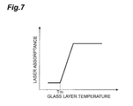
- the inventors conducted diligent studies and, as a result, have found out that the burning of a glass layer by laser beam irradiation leads to damages in a glass member because of the fact that the laser absorptance of the glass layer drastically increases when the temperature of the glass layer exceeds its melting point Tm at the time of burning as illustrated in FIG. 7 . That is, in the glass layer firmly attached to the glass member, voids formed by the removal of the binder and the particle property of the glass frit produce scattering of light exceeding the absorption characteristic of the laser-absorbing pigment, so that the laser absorptance is low (e.g., the glass layer appears whiter under visible light).
- the glass frit melts to fill the voids and loses the particle property, so that the laser-absorbing pigment remarkably exhibits its absorption characteristic, whereby the glass layer drastically increases its laser absorptance (e.g., appears darker under visible light).
- the laser irradiation at the laser power P lets the glass layer reach a temperature Ta higher than the crystallization temperature Tc.
- the change in color of the glass layer under visible light in the case where the laser absorptance of the glass layer is enhanced by the melting of the glass layer is not limited to the change from a whiter state to a darker state.
- laser-absorbing pigments for near-infrared laser beams include those exhibiting green when the glass layer melts.
- the glass fusing method in accordance with the present invention is a glass fusing method for manufacturing a glass fusing structure by fusing first and second glass members together, the method comprising the steps of disposing a glass layer between the first glass member and a thermal conductor along a region to be fused, the glass layer being formed by removing an organic solvent and a binder from a paste layer containing a glass powder, a laser-absorbing material, the organic solvent and the binder; irradiating the region to be fused therealong with a first laser beam while using the thermal conductor as a heatsink, so as to melt the glass layer disposed between the first glass member and the thermal conductor, and fix the glass layer to the first glass member; and overlaying the second glass member on the first glass member having the glass layer fixed thereto such that the glass layer is interposed therebetween, and irradiating the region to be fused therealong with a second laser beam, so as to fuse the first and second glass members together.
- the glass layer is disposed between the first glass member and the thermal conductor along the region to be fused, and the first laser beam is emitted while using the thermal conductor as a heatsink, so as to melt the glass layer and fix the glass layer to the first glass member.
- the thermal conductor serves as the heatsink and draws heat from the glass layer, thereby inhibiting the glass layer from falling into an excessive heat input state.
- the thermal conductor has a thermal conductivity higher than that of the glass powder. This allows the thermal conductor to serve as the heatsink and draw heat efficiently from the glass layer. More preferably, in this case, the thermal conductivity of the thermal conductor is higher than that of the first glass member. This allows the thermal conductor to serve as the heatsink and draw heat more efficiently from the glass layer.
- the difference between coefficients of linear expansion of the glass powder and the thermal conductor is greater than the difference between coefficients of linear expansion of the glass powder and the first glass member. This can reliably prevent the glass layer from firmly attaching to the thermal conductor when fixing the glass layer to the first glass member.
- the first laser beam irradiates the glass layer from the first glass member side. This can fully heat the interface part between the first glass member and the glass layer, thereby strongly fixing the glass layer to the first glass member.
- the present invention can efficiently fuse glass members together by preventing the glass members from being damaged.
- FIG. 1 is a perspective view for explaining a glass fusing structure manufactured by an embodiment of the glass fusing method in accordance with the present invention
- FIG. 2 is a perspective view for explaining the glass fusing method for manufacturing the glass fusing structure of FIG. 1 ;
- FIG. 3 is a sectional view for explaining the glass fusing method for manufacturing the glass fusing structure of FIG. 1 ;
- FIG. 4 is a perspective view for explaining the glass fusing method for manufacturing the glass fusing structure of FIG. 1 ;
- FIG. 5 is a perspective view for explaining the glass fusing method for manufacturing the glass fusing structure of FIG. 1 ;
- FIG. 6 is a sectional view for explaining the glass fusing method for manufacturing the glass fusing structure of FIG. 1 ;
- FIG. 7 is a graph illustrating the relationship between the temperature and laser absorptance of a glass layer.
- FIG. 8 is a graph illustrating the relationship between the laser power and the temperature of the glass layer.
- FIG. 1 is a perspective view of the glass fusing structure manufactured by an embodiment of the glass fusing method in accordance with the present invention.
- the glass fusing structure 1 is a fusion-bonded grass structure in which glass members (first and second glass members) 4 , 5 are fused together through a glass layer 3 formed along a region R to be fused.
- each of the glass members 4 , 5 is a rectangular plate-shaped member made of alkali-free glass having a thickness of 0.7 mm, while the region R to be fused is set like a rectangular ring along the outer edges of the glass members 4 , 5 .
- the glass layer 3 is made of low-melting glass (vanadium-phosphate-based glass, lead borosilicate glass, or the like) and formed into a rectangular ring along the region R to be fused.
- a frit paste is applied by a dispenser, screen-printing, or the like, so as to form a paste layer 6 on a surface 4 a of the glass member 4 along the region R to be fused.
- An example of the frit paste is one formed by kneading a powdery glass frit (glass powder) 2 made of amorphous low-melting glass (vanadium-phosphate-based glass, lead borosilicate glass, or the like), a laser-absorbing pigment (laser-absorbing material) which is an inorganic pigment such as iron oxide, an organic solvent such as amyl acetate, and a binder which is a resin component (such as acrylic resin) thermally decomposable at the glass softening temperature or lower.
- the paste layer 6 contains the glass frit, laser-absorbing pigment, organic solvent, and binder.
- the paste layer 6 is dried, so as to eliminate the organic solvent, and further heated, so as to remove the binder, thereby firmly attaching the glass layer 3 to the surface 4 a of the glass member 4 along the region R to be fused.
- voids formed by the removal of the binder and the particle property of the glass frit 2 produce scattering of light exceeding the absorption characteristic of the laser-absorbing pigment, so that the glass layer 3 firmly attached to the surface 4 a of the glass member 4 is in a low laser absorptance state (e.g., appears whiter under visible light).
- the glass member 4 is mounted on a surface 7 a (a polished surface here) of a planar thermal conductor 7 made of aluminum, such that the glass layer 3 is interposed therebetween.
- a surface 7 a a polished surface here
- the glass layer 3 formed by removing the organic solvent and binder from the paste layer 6 is disposed between the glass member 4 and the thermal conductor 7 along the region R to be fused.
- the region R to be fused is irradiated therealong with a laser beam (first laser beam L 1 ) such that a converging spot is located at the glass layer 3 .
- first laser beam L 1 a laser beam
- the glass layer 3 burned onto the surface 4 a of the glass member 4 loses its particle property and remarkably exhibits the absorption characteristic of the laser-absorbing pigment, thereby attaining a high laser absorptance state (e.g., appearing darker under visible light).
- the glass layer 3 burned onto the surface 4 a of the glass member 4 is in a state where irregularities on its surface 3 a opposite from the glass member 4 are made flat.
- the thermal conductor 7 serves as the heatsink and draws heat from the glass layer 3 , thereby inhibiting the glass layer 3 from falling into an excessive heat input state.
- the thermal conductor 7 is made of aluminum, so that the thermal conductivity of the thermal conductor 7 is higher than that of the glass frit 2 and that of the glass member 4 , whereby the heat is dissipated from the glass layer 3 to the thermal conductor 7 very efficiently.
- the glass layer 3 does not firmly attach to the surface 7 a of the thermal conductor 7 at the time of burning.
- the glass member 5 is overlaid on the glass member 4 having the glass layer 3 burned thereonto, such that the glass layer 3 is interposed therebetween.
- the surface 3 a of the glass layer 3 is made flat, a surface 5 a of the glass member 5 comes into contact with the surface 3 a of the glass layer 3 without gaps.
- the region R to be fused is irradiated therealong with a laser beam (second laser beam) L 2 while locating a converging spot at the glass layer 3 .
- the glass layer 3 in a high laser absorptance state absorbs the laser beam L 2 , so as to melt and resolidify the glass layer 3 and its peripheral portions (the portions of the glass members 4 , 5 on their surfaces 4 a , 5 a ), thereby bonding the glass members 4 , 5 together.
- the surface 5 a of the glass member 5 is in contact with the surface 3 a of the glass layer 3 without gaps, the glass members 4 , 5 are uniformly fused together along the region R to be fused.
- the glass fusing method for manufacturing the glass fusing structure 1 disposes the glass layer 3 between the glass member 4 and the thermal conductor 7 along the region R to be fused and then emits the laser beam L 1 while using the thermal conductor 7 as a heatsink, so as to melt the glass layer 3 , thereby burning and fixing the glass layer 3 onto the glass member 4 .
- the thermal conductor 7 serves as the heatsink and draws heat from the glass layer 3 , thereby inhibiting the glass layer 3 from falling into an excessive heat input state.
- the laser beam L 2 it is not necessary for the laser beam L 2 to be emitted with such a high laser power as to melt the portion of the glass layer 3 on the surface 3 a at the time of fusing the glass members 4 , 5 together thereafter, whereby cracks can be prevented from occurring in the glass members 4 , 5 because of a heat shock due to excessive heat input as in the burning of the glass layer 3 .
- the above-mentioned glass fusing method can efficiently fuse the glass members 4 , 5 together by preventing the glass members 4 , 5 from being damaged.
- the above-mentioned glass fusing method irradiates the glass layer 3 with the laser beam L 1 from the glass member 4 side. Therefore, the interface part between the glass member 4 and the glass layer 3 is fully heated. Hence, the glass layer 3 can be strongly burned and fixed onto the glass member 4 . This can also more reliably prevent the portion of the glass layer 3 (portion of the glass layer 3 on the surface 3 a ) located on the side of the glass member 5 to which it is to be fused from being crystallized by excessive heat input.
- the portion of the glass layer 3 located on the side of the glass member 4 onto which it is to be burned may be crystallized by irradiation with the laser beam L 1 .
- the portion of the glass layer 3 (the portion of the glass layer 3 on the surface 3 a ) located on the side of the glass member 5 to which it is to be fused may be crystallized by irradiation with the laser beam L 2 . This is because finally crystallizing the glass layer 3 reduces the coefficient of linear expansion of the glass layer 3 in the glass fusing structure 1 .
- Organic EL packages and the like have a small size themselves, for which thinner glass members 4 , 5 are used, so that low expansion glass is often chosen as a material for the glass members 4 , 5 in order to make them harder to break.
- the glass layer 3 in order for the glass layer 3 to have a coefficient of linear expansion matching that of the glass members 4 , 5 (i.e., in order to lower the coefficient of linear expansion of the glass layer 3 ), the glass layer 3 is made to contain a large amount of a filler constituted by ceramics or the like. By containing the large amount of the filler, the glass layer 3 changes its laser absorptance greatly between before and after irradiation with the laser beam L 1 . Therefore, the above-mentioned glass fusing method is effective in particular when low expansion glass is chosen as the material for the glass members 4 , 5 .
- the present invention is not limited to the above-mentioned embodiment.
- a thermal conductor 7 made of a material transparent to the laser beam L 1 may be used, so as to irradiate the glass layer 3 with the laser beam L 1 through the thermal conductor 7 from the side opposite from the glass member 4 .
- the glass member 4 may be mounted on the surface 7 a of the thermal conductor 7 such that the glass layer 3 is interposed therebetween, whereby the glass layer 3 formed by removing the organic solvent and binder from the paste layer 6 is disposed between the glass member 4 and the thermal conductor 7 along the region R to be fused.
- the present invention can efficiently fuse glass members together by preventing the glass members from being damaged.
Abstract
A glass layer fixing method for manufacturing a glass layer fixing member by fixing a glass layer to a first glass member, includes the steps of disposing the glass layer on the first glass member along a region to be fused, the glass layer containing a glass powder and a laser-absorbing material and irradiating the region to be fused therealong with a first laser beam, so as to melt the glass layer, fix the glass layer to the first glass member, and increase a laser absorptance of the glass layer.
Description
This is a continuation application of copending application Ser. No. 12/994,320, having a §371 date of Nov. 23, 2010, which is a national stage filing based on PCT International Application No. PCT/JP2009/058764, filed on May 11, 2009. The copending application Ser. No. 12/994,320 is incorporated by reference herein in its entirety.
The present invention relates to a glass fusing method for manufacturing a glass fusing structure by fusing glass members together.
Known as a conventional glass fusing method in the above-mentioned technical field is one comprising burning a glass layer containing a laser-absorbing pigment onto one glass member along a region to be fused, then overlaying the other glass member on the former glass member such that the glass layer is interposed therebetween, and irradiating the region to be fused therealong with a laser beam, so as to fuse one glass member and the other glass member together.
A typical technique for burning a glass layer onto a glass member is one comprising firmly attaching a glass layer to the glass member by removing an organic solvent and a binder from a paste layer containing a glass frit, a laser-absorbing pigment, the organic solvent, and the binder; and then heating the glass member having the glass layer firmly attached thereto in a firing furnace, so as to melt the glass layer, thereby burning the glass layer onto the glass member (see, for example, Patent Literature 1).
On the other hand, proposed from the viewpoint of suppressing the increase in energy consumption and burning time caused by the use of the firing furnace (i.e., the viewpoint of high efficiency) is a technique which irradiates a glass layer attached to a glass member with a laser beam, so as to melt the glass layer, thereby burning the glass layer onto the glass member (see, for example, Patent Literature 2).
- Patent Literature 1: Japanese Translated International Patent Application Laid-Open No. 2006-524419
- Patent Literature 2: Japanese Patent Application Laid-Open No. 2002-366050
However, there have been cases where glass members having glass layers burned thereonto by laser light irradiation are damaged by cracks and the like occurring at the time of burning and their fusion thereafter.
In view of such circumstances, it is an object of the present invention to provide a glass fusing method which can efficiently fuse glass members together by preventing the glass members from being damaged.
For achieving the above-mentioned object, the inventors conducted diligent studies and, as a result, have found out that the burning of a glass layer by laser beam irradiation leads to damages in a glass member because of the fact that the laser absorptance of the glass layer drastically increases when the temperature of the glass layer exceeds its melting point Tm at the time of burning as illustrated in FIG. 7 . That is, in the glass layer firmly attached to the glass member, voids formed by the removal of the binder and the particle property of the glass frit produce scattering of light exceeding the absorption characteristic of the laser-absorbing pigment, so that the laser absorptance is low (e.g., the glass layer appears whiter under visible light). When a laser beam is emitted with such a laser power P that the glass layer attains a temperature Tp higher than the melting point Tm but lower than its crystallization temperature Tc as illustrated in FIG. 8 , the glass frit melts to fill the voids and loses the particle property, so that the laser-absorbing pigment remarkably exhibits its absorption characteristic, whereby the glass layer drastically increases its laser absorptance (e.g., appears darker under visible light). This causes the glass layer to absorb the laser beam more than expected, thereby generating cracks in the glass member because of a heat shock due to excessive heat input. In practice, as illustrated in FIG. 8 , the laser irradiation at the laser power P lets the glass layer reach a temperature Ta higher than the crystallization temperature Tc. When a portion of the glass layer on the side opposite from the glass member onto which it is to be burned (i.e., a portion of the glass layer located on the side of the glass member to which it is to be fused) is crystallized by excessive heat input, the melting point rises in this portion. This makes it necessary to emit the laser beam with a higher laser power at the time of fusing the glass members together thereafter so as to melt the portion of the glass layer located on the side of the glass member to which it is to be fused, whereby cracks are generated in the glass member because of a heat shock due to excessive heat input as in the burning. The inventors have conducted further studies based on this finding, thereby completing the present invention. The change in color of the glass layer under visible light in the case where the laser absorptance of the glass layer is enhanced by the melting of the glass layer is not limited to the change from a whiter state to a darker state. For example, laser-absorbing pigments for near-infrared laser beams include those exhibiting green when the glass layer melts.
The glass fusing method in accordance with the present invention is a glass fusing method for manufacturing a glass fusing structure by fusing first and second glass members together, the method comprising the steps of disposing a glass layer between the first glass member and a thermal conductor along a region to be fused, the glass layer being formed by removing an organic solvent and a binder from a paste layer containing a glass powder, a laser-absorbing material, the organic solvent and the binder; irradiating the region to be fused therealong with a first laser beam while using the thermal conductor as a heatsink, so as to melt the glass layer disposed between the first glass member and the thermal conductor, and fix the glass layer to the first glass member; and overlaying the second glass member on the first glass member having the glass layer fixed thereto such that the glass layer is interposed therebetween, and irradiating the region to be fused therealong with a second laser beam, so as to fuse the first and second glass members together.
In this glass fusing method, the glass layer is disposed between the first glass member and the thermal conductor along the region to be fused, and the first laser beam is emitted while using the thermal conductor as a heatsink, so as to melt the glass layer and fix the glass layer to the first glass member. While the glass layer drastically increases its laser absorptance when being fixed, the thermal conductor serves as the heatsink and draws heat from the glass layer, thereby inhibiting the glass layer from falling into an excessive heat input state. As a consequence, even when the glass layer is fixed to the first glass member by irradiation with the first laser beam, the glass members can be prevented from being damaged by cracks occurring therein and the like at the time of fixing the glass layer and fusing the glass members together thereafter. Therefore, this glass fusing method can prevent the glass members from being damaged and efficiently fuse the glass members together.
Preferably, in the glass fusing method in accordance with the present invention, the thermal conductor has a thermal conductivity higher than that of the glass powder. This allows the thermal conductor to serve as the heatsink and draw heat efficiently from the glass layer. More preferably, in this case, the thermal conductivity of the thermal conductor is higher than that of the first glass member. This allows the thermal conductor to serve as the heatsink and draw heat more efficiently from the glass layer.
Preferably, in the glass fusing method in accordance with the present invention, the difference between coefficients of linear expansion of the glass powder and the thermal conductor is greater than the difference between coefficients of linear expansion of the glass powder and the first glass member. This can reliably prevent the glass layer from firmly attaching to the thermal conductor when fixing the glass layer to the first glass member.
Preferably, in the glass fusing method in accordance with the present invention, the first laser beam irradiates the glass layer from the first glass member side. This can fully heat the interface part between the first glass member and the glass layer, thereby strongly fixing the glass layer to the first glass member.
The present invention can efficiently fuse glass members together by preventing the glass members from being damaged.
In the following, preferred embodiments of the present invention will be explained in detail with reference to the drawings. In the drawings, the same or equivalent parts will be referred to with the same signs while omitting their overlapping descriptions.
The glass fusing method for manufacturing the above-mentioned glass fusing structure 1 will now be explained.
First, as illustrated in FIG. 2 , a frit paste is applied by a dispenser, screen-printing, or the like, so as to form a paste layer 6 on a surface 4 a of the glass member 4 along the region R to be fused. An example of the frit paste is one formed by kneading a powdery glass frit (glass powder) 2 made of amorphous low-melting glass (vanadium-phosphate-based glass, lead borosilicate glass, or the like), a laser-absorbing pigment (laser-absorbing material) which is an inorganic pigment such as iron oxide, an organic solvent such as amyl acetate, and a binder which is a resin component (such as acrylic resin) thermally decomposable at the glass softening temperature or lower. The paste layer 6 contains the glass frit, laser-absorbing pigment, organic solvent, and binder.
Subsequently, the paste layer 6 is dried, so as to eliminate the organic solvent, and further heated, so as to remove the binder, thereby firmly attaching the glass layer 3 to the surface 4 a of the glass member 4 along the region R to be fused. Here, voids formed by the removal of the binder and the particle property of the glass frit 2 produce scattering of light exceeding the absorption characteristic of the laser-absorbing pigment, so that the glass layer 3 firmly attached to the surface 4 a of the glass member 4 is in a low laser absorptance state (e.g., appears whiter under visible light).
Thereafter, as illustrated in FIG. 3 , the glass member 4 is mounted on a surface 7 a (a polished surface here) of a planar thermal conductor 7 made of aluminum, such that the glass layer 3 is interposed therebetween. As a consequence, the glass layer 3 formed by removing the organic solvent and binder from the paste layer 6 is disposed between the glass member 4 and the thermal conductor 7 along the region R to be fused.
Next, while using the thermal conductor 7 as a heatsink, the region R to be fused is irradiated therealong with a laser beam (first laser beam L1) such that a converging spot is located at the glass layer 3. This melts and resolidifies the glass layer 3 disposed between the glass member 4 and the thermal conductor 7, thereby burning the glass layer 3 onto the surface 4 a of the glass member 4. As the voids are filled by the melting of the glass frit 2, the glass layer 3 burned onto the surface 4 a of the glass member 4 loses its particle property and remarkably exhibits the absorption characteristic of the laser-absorbing pigment, thereby attaining a high laser absorptance state (e.g., appearing darker under visible light). The glass layer 3 burned onto the surface 4 a of the glass member 4 is in a state where irregularities on its surface 3 a opposite from the glass member 4 are made flat.
At the time of burning the glass layer 3, the thermal conductor 7 serves as the heatsink and draws heat from the glass layer 3, thereby inhibiting the glass layer 3 from falling into an excessive heat input state. Here, the thermal conductor 7 is made of aluminum, so that the thermal conductivity of the thermal conductor 7 is higher than that of the glass frit 2 and that of the glass member 4, whereby the heat is dissipated from the glass layer 3 to the thermal conductor 7 very efficiently.
Since the difference between the coefficients of linear expansion of the glass frit 2 and thermal conductor 7 is greater than the difference between the coefficients of linear expansion of the glass frit 2 and glass member 4, the glass layer 3 does not firmly attach to the surface 7 a of the thermal conductor 7 at the time of burning. While this fact indicates that it will be more preferred if the difference between the coefficients of linear expansion of the glass frit 2 and thermal conductor 7 is greater, not only aluminum (having a coefficient of linear expansion of 23×10−6/K) but stainless steel (having a coefficient of linear expansion of 17.3×10⁻⁶/K) or copper (having a coefficient of linear expansion of 16.8×10⁻⁶/K) can also constitute the thermal conductor 7 for use in combination with the glass frit 2 made of vanadium-phosphate-based glass (having a coefficient of linear expansion of 7.0×10⁻⁶/K) or lead borosilicate glass (having a coefficient of linear expansion of 13×10−6/K).
Subsequent to the burning of the glass layer 3, as illustrated in FIG. 4 , the glass member 5 is overlaid on the glass member 4 having the glass layer 3 burned thereonto, such that the glass layer 3 is interposed therebetween. Here, since the surface 3 a of the glass layer 3 is made flat, a surface 5 a of the glass member 5 comes into contact with the surface 3 a of the glass layer 3 without gaps.
Next, as illustrated in FIG. 5 , the region R to be fused is irradiated therealong with a laser beam (second laser beam) L2 while locating a converging spot at the glass layer 3. As a consequence, the glass layer 3 in a high laser absorptance state absorbs the laser beam L2, so as to melt and resolidify the glass layer 3 and its peripheral portions (the portions of the glass members 4, 5 on their surfaces 4 a, 5 a), thereby bonding the glass members 4, 5 together. Here, since the surface 5 a of the glass member 5 is in contact with the surface 3 a of the glass layer 3 without gaps, the glass members 4, 5 are uniformly fused together along the region R to be fused.
As explained in the foregoing, the glass fusing method for manufacturing the glass fusing structure 1 disposes the glass layer 3 between the glass member 4 and the thermal conductor 7 along the region R to be fused and then emits the laser beam L1 while using the thermal conductor 7 as a heatsink, so as to melt the glass layer 3, thereby burning and fixing the glass layer 3 onto the glass member 4. While the laser absorptance of the glass layer 3 rapidly increases at the time of burning the glass layer 3, the thermal conductor 7 serves as the heatsink and draws heat from the glass layer 3, thereby inhibiting the glass layer 3 from falling into an excessive heat input state. This can prevent cracks from occurring in the glass members 4, 5 because of a heat shock due to excessive heat input at the time of burning the glass layer 3 even when the glass layer 3 is burned by irradiation with the laser beam L1. Further, at the time of burning the glass layer 3, the portion of the glass layer 3 on the surface 3 a (i.e., the portion of the glass layer 3 located on the side of the glass member 5 to which it is to be fused) is not crystallized by excessive heat input and thus does not raise its melting point. Therefore, it is not necessary for the laser beam L2 to be emitted with such a high laser power as to melt the portion of the glass layer 3 on the surface 3 a at the time of fusing the glass members 4, 5 together thereafter, whereby cracks can be prevented from occurring in the glass members 4, 5 because of a heat shock due to excessive heat input as in the burning of the glass layer 3. Hence, the above-mentioned glass fusing method can efficiently fuse the glass members 4, 5 together by preventing the glass members 4, 5 from being damaged.
The above-mentioned glass fusing method irradiates the glass layer 3 with the laser beam L1 from the glass member 4 side. Therefore, the interface part between the glass member 4 and the glass layer 3 is fully heated. Hence, the glass layer 3 can be strongly burned and fixed onto the glass member 4. This can also more reliably prevent the portion of the glass layer 3 (portion of the glass layer 3 on the surface 3 a) located on the side of the glass member 5 to which it is to be fused from being crystallized by excessive heat input.
At the time of burning the glass layer 3, the portion of the glass layer 3 located on the side of the glass member 4 onto which it is to be burned may be crystallized by irradiation with the laser beam L1. At the time of fusing the glass members 4, 5 together, the portion of the glass layer 3 (the portion of the glass layer 3 on the surface 3 a) located on the side of the glass member 5 to which it is to be fused may be crystallized by irradiation with the laser beam L2. This is because finally crystallizing the glass layer 3 reduces the coefficient of linear expansion of the glass layer 3 in the glass fusing structure 1.
Organic EL packages and the like have a small size themselves, for which thinner glass members 4, 5 are used, so that low expansion glass is often chosen as a material for the glass members 4, 5 in order to make them harder to break. Here, in order for the glass layer 3 to have a coefficient of linear expansion matching that of the glass members 4, 5 (i.e., in order to lower the coefficient of linear expansion of the glass layer 3), the glass layer 3 is made to contain a large amount of a filler constituted by ceramics or the like. By containing the large amount of the filler, the glass layer 3 changes its laser absorptance greatly between before and after irradiation with the laser beam L1. Therefore, the above-mentioned glass fusing method is effective in particular when low expansion glass is chosen as the material for the glass members 4, 5.
The present invention is not limited to the above-mentioned embodiment.
For example, as illustrated in FIG. 6 , a thermal conductor 7 made of a material transparent to the laser beam L1 may be used, so as to irradiate the glass layer 3 with the laser beam L1 through the thermal conductor 7 from the side opposite from the glass member 4.
After firmly attaching the glass layer 3 to the surface 7 a of the thermal conductor 7 along the region R to be fused, the glass member 4 may be mounted on the surface 7 a of the thermal conductor 7 such that the glass layer 3 is interposed therebetween, whereby the glass layer 3 formed by removing the organic solvent and binder from the paste layer 6 is disposed between the glass member 4 and the thermal conductor 7 along the region R to be fused.
The present invention can efficiently fuse glass members together by preventing the glass members from being damaged.
1 . . . glass fusing structure; 2 . . . glass frit (glass powder); 3 . . . glass layer; 4 . . . glass member (first glass member); 5 . . . glass member (second glass member); 6 . . . paste layer; 7 . . . thermal conductor; R . . . region to be fused; L1 . . . laser beam (first laser beam); L2 . . . laser beam (second laser beam)
Claims (2)
1. A method for manufacturing a glass layer fixing member by fixing a glass layer to a first glass member, the method comprising the steps of:
disposing the glass layer on the first glass member along a region to be fused, the glass layer containing a glass powder and a laser-absorbing material; and
irradiating the region to be fused therealong with a first laser beam, so as to melt the glass layer, fix the glass layer to the first glass member, and increase a laser absorptance of the glass layer,
wherein a laser absorbance rate of the glass layer is increased when the glass powder melts to fill voids causing loss of a particle property;
overlaying a second glass member on the first glass member having the glass layer fixed thereto along the region to be fused such that the glass layer is interposed therebetween; and
irradiating the region to be fused therealong with a second laser beam so as to fuse the first and second glass members together,
wherein disposing the glass layer on the first glass member and irradiating the region to be fused with a first laser beam is implemented before the step of overlaying a second glass member.
2. The method according to claim 1 , wherein the glass layer is irradiated with the first laser beam such that the glass layer attains a temperature higher than its melting point but lower than its crystallization temperature.
Priority Applications (1)
| Application Number | Priority Date | Filing Date | Title |
|---|---|---|---|
| US13/345,199 US9181126B2 (en) | 2008-05-26 | 2012-01-06 | Glass fusion method |
Applications Claiming Priority (5)
| Application Number | Priority Date | Filing Date | Title |
|---|---|---|---|
| JPP2008-136843 | 2008-05-26 | ||
| JP2008136843A JP5308718B2 (en) | 2008-05-26 | 2008-05-26 | Glass welding method |
| PCT/JP2009/058764 WO2009145046A1 (en) | 2008-05-26 | 2009-05-11 | Glass fusion method |
| US99432010A | 2010-11-23 | 2010-11-23 | |
| US13/345,199 US9181126B2 (en) | 2008-05-26 | 2012-01-06 | Glass fusion method |
Related Parent Applications (3)
| Application Number | Title | Priority Date | Filing Date |
|---|---|---|---|
| PCT/JP2009/058764 Continuation WO2009145046A1 (en) | 2008-05-26 | 2009-05-11 | Glass fusion method |
| US12/994,320 Continuation US8516852B2 (en) | 2008-05-26 | 2009-05-11 | Glass fusion method |
| US99432010A Continuation | 2008-05-26 | 2010-11-23 |
Publications (2)
| Publication Number | Publication Date |
|---|---|
| US20120151965A1 US20120151965A1 (en) | 2012-06-21 |
| US9181126B2 true US9181126B2 (en) | 2015-11-10 |
Family
ID=41376931
Family Applications (2)
| Application Number | Title | Priority Date | Filing Date |
|---|---|---|---|
| US12/994,320 Active 2029-07-25 US8516852B2 (en) | 2008-05-26 | 2009-05-11 | Glass fusion method |
| US13/345,199 Active US9181126B2 (en) | 2008-05-26 | 2012-01-06 | Glass fusion method |
Family Applications Before (1)
| Application Number | Title | Priority Date | Filing Date |
|---|---|---|---|
| US12/994,320 Active 2029-07-25 US8516852B2 (en) | 2008-05-26 | 2009-05-11 | Glass fusion method |
Country Status (7)
| Country | Link |
|---|---|
| US (2) | US8516852B2 (en) |
| JP (1) | JP5308718B2 (en) |
| KR (2) | KR20110021725A (en) |
| CN (1) | CN102046555B (en) |
| DE (1) | DE112009001365B4 (en) |
| TW (2) | TWI404695B (en) |
| WO (1) | WO2009145046A1 (en) |
Families Citing this family (16)
| Publication number | Priority date | Publication date | Assignee | Title |
|---|---|---|---|---|
| JP5308717B2 (en) * | 2008-05-26 | 2013-10-09 | 浜松ホトニクス株式会社 | Glass welding method |
| JP5308718B2 (en) | 2008-05-26 | 2013-10-09 | 浜松ホトニクス株式会社 | Glass welding method |
| JP5535654B2 (en) * | 2008-06-11 | 2014-07-02 | 浜松ホトニクス株式会社 | Glass welding method |
| JP5535652B2 (en) * | 2008-06-11 | 2014-07-02 | 浜松ホトニクス株式会社 | Glass welding method |
| DE112009001456T5 (en) * | 2008-06-23 | 2011-05-19 | Hamamatsu Photonics K.K., Hamamatsu-shi | Glass fusing method |
| JP5481167B2 (en) * | 2009-11-12 | 2014-04-23 | 浜松ホトニクス株式会社 | Glass welding method |
| JP5535590B2 (en) | 2009-11-25 | 2014-07-02 | 浜松ホトニクス株式会社 | Glass welding method and glass layer fixing method |
| JP5535588B2 (en) | 2009-11-25 | 2014-07-02 | 浜松ホトニクス株式会社 | Glass welding method and glass layer fixing method |
| JP5535589B2 (en) * | 2009-11-25 | 2014-07-02 | 浜松ホトニクス株式会社 | Glass welding method and glass layer fixing method |
| JP5525246B2 (en) | 2009-11-25 | 2014-06-18 | 浜松ホトニクス株式会社 | Glass welding method and glass layer fixing method |
| JP5481173B2 (en) * | 2009-11-25 | 2014-04-23 | 浜松ホトニクス株式会社 | Glass welding method and glass layer fixing method |
| JP5567319B2 (en) | 2009-11-25 | 2014-08-06 | 浜松ホトニクス株式会社 | Glass welding method and glass layer fixing method |
| JP5466929B2 (en) * | 2009-11-25 | 2014-04-09 | 浜松ホトニクス株式会社 | Glass welding method and glass layer fixing method |
| JP5481172B2 (en) | 2009-11-25 | 2014-04-23 | 浜松ホトニクス株式会社 | Glass welding method and glass layer fixing method |
| US20180127296A1 (en) * | 2016-11-10 | 2018-05-10 | Goodrich Corporation | Additive manufacture of optical components |
| CN106925891A (en) * | 2017-05-05 | 2017-07-07 | 湖南理工学院 | It is a kind of while the method for realizing multiple pieces of glass encapsulation and internal processing |
Citations (97)
| Publication number | Priority date | Publication date | Assignee | Title |
|---|---|---|---|---|
| US3453097A (en) | 1964-10-19 | 1969-07-01 | Gerhard Mensel Glasbearbeitung | Method of working glass with absorbent by a laser beam |
| US3663793A (en) * | 1971-03-30 | 1972-05-16 | Westinghouse Electric Corp | Method of decorating a glazed article utilizing a beam of corpuscular energy |
| US4343833A (en) | 1979-06-26 | 1982-08-10 | Mitsubishi Denki Kabushiki Kaisha | Method of manufacturing thermal head |
| JPH02120259A (en) | 1988-10-28 | 1990-05-08 | Toshiba Corp | Sealed and bonded glass and production thereof |
| JPH05166462A (en) | 1991-12-17 | 1993-07-02 | Matsushita Electric Ind Co Ltd | Manufacture of vacuum vessel for flat display device |
| US5489321A (en) | 1994-07-14 | 1996-02-06 | Midwest Research Institute | Welding/sealing glass-enclosed space in a vacuum |
| JP2000313630A (en) | 1998-08-07 | 2000-11-14 | Shin Meiwa Ind Co Ltd | Method for fusing glass, device for fusing glass, fused glass and method for producing fused glass |
| CN1329395A (en) | 2000-03-10 | 2002-01-02 | 精工爱普生株式会社 | Package sealing method, method for manufacturing module fr electronic device sealing device and packafge element |
| JP2002015108A (en) | 2000-06-30 | 2002-01-18 | Nomura Holding Inc | Device and method for analyzing enterprise value |
| JP2002224871A (en) | 2001-01-31 | 2002-08-13 | Seiko Epson Corp | Laser beam cutting method, manufacturing method for optoelectronic device, optoelectronic device, electronic device and laser beam cutting device |
| KR100350323B1 (en) | 2000-12-28 | 2002-08-29 | 박재홍 | A method for sealing a flat panel display in vacuum atmosphere |
| JP2002287107A (en) | 2001-03-28 | 2002-10-03 | Hitachi Ltd | Liquid crystal display device and method for manufacturing the same |
| JP2002366050A (en) | 2001-06-12 | 2002-12-20 | Matsushita Electric Ind Co Ltd | Method for manufacturing image display device, manufacturing device and image display device manufactured by using the same |
| JP2002367514A (en) | 2001-06-12 | 2002-12-20 | Matsushita Electric Ind Co Ltd | Method and device for manufacturing display panel |
| US6565400B1 (en) | 2001-06-26 | 2003-05-20 | Candescent Technologies Corporation | Frit protection in sealing process for flat panel displays |
| US20040069017A1 (en) | 2001-10-09 | 2004-04-15 | Delta Optoelectronics Inc. | Encapsulation of a display element and method of forming the same |
| JP2004182567A (en) | 2002-12-05 | 2004-07-02 | Nippon Sheet Glass Co Ltd | Method for manufacturing vacuum glass panel and vacuum glass panel manufactured by using the method |
| US20040207314A1 (en) | 2003-04-16 | 2004-10-21 | Aitken Bruce G. | Glass package that is hermetically sealed with a frit and method of fabrication |
| JP2005007665A (en) | 2003-06-17 | 2005-01-13 | Hamamatsu Photonics Kk | Laser welding method and laser welding apparatus |
| US20050103755A1 (en) | 2003-11-13 | 2005-05-19 | Baker Martin C. | Hand-held laser welding wand reflection shield |
| JP2005213125A (en) | 2004-02-02 | 2005-08-11 | Futaba Corp | Method for manufacturing electron tube and airtight container for electron tube |
| US20060082298A1 (en) | 2004-10-20 | 2006-04-20 | Becken Keith J | Optimization of parameters for sealing organic emitting light diode (OLED) displays |
| TWI255934B (en) | 1998-12-04 | 2006-06-01 | Samsung Electronics Co Ltd | A substrate and a liquid crystal display panel capable of being cut by using a laser and a method for manufacturing the same |
| JP2006151774A (en) | 2004-12-01 | 2006-06-15 | Nippon Electric Glass Co Ltd | Sealing material |
| CN1798708A (en) | 2003-04-16 | 2006-07-05 | 康宁股份有限公司 | Hermetically sealed glass package and method of fabrication |
| CN1836177A (en) | 2003-07-16 | 2006-09-20 | 3M创新有限公司 | Laminates and methods of making same |
| KR20070003681A (en) | 2005-06-30 | 2007-01-05 | 삼성에스디아이 주식회사 | Glass-to-glass joining method using laser, vacuum envelope manufactured by the method |
| JP2007090405A (en) | 2005-09-29 | 2007-04-12 | Epson Toyocom Corp | Laminated optical element, and its manufacturing method |
| US20070128967A1 (en) | 2005-12-06 | 2007-06-07 | Becken Keith J | Method of making a glass envelope |
| WO2007067533A2 (en) | 2005-12-06 | 2007-06-14 | Corning Incorporated | System and method for frit sealing glass packages |
| CN101005915A (en) | 2004-07-30 | 2007-07-25 | 康宁股份有限公司 | Process and apparatus for scoring brittle material |
| US20070173167A1 (en) | 2006-01-26 | 2007-07-26 | Young Seo Choi | Organic light-emitting display device and method of fabricating the same |
| US20070170845A1 (en) * | 2006-01-26 | 2007-07-26 | Dong Soo Choi | Organic light emitting display device |
| JP2007264135A (en) | 2006-03-27 | 2007-10-11 | Nec Corp | Laser cutting method, manufacturing method of display device, and display device |
| CN101103429A (en) | 2004-10-13 | 2008-01-09 | 康宁股份有限公司 | Hermetically sealed glass package and method of fabrication |
| CN101139165A (en) | 2006-08-18 | 2008-03-12 | 康宁股份有限公司 | Boro-silicate glass frits for hermetic sealing of light emitting device displays |
| US20080106194A1 (en) | 2006-11-07 | 2008-05-08 | Stephan Lvovich Logunov | Seal for light emitting display device, method, and apparatus |
| JP2008115057A (en) | 2006-11-07 | 2008-05-22 | Electric Power Dev Co Ltd | Sealant, manufacturing process of glass panel and dye-sensitized solar cell |
| JP2008115067A (en) | 2006-11-07 | 2008-05-22 | Lemi Ltd | Method of cutting flat panel display thin plate |
| JP2008127223A (en) | 2006-11-17 | 2008-06-05 | Lemi Ltd | Method for cutting flat panel display thin glass sheet |
| US20080135175A1 (en) | 2005-08-09 | 2008-06-12 | Asahi Glass Company, Limited | Thin plate glass laminate and process for producing display device using thin plate glass laminate |
| JP2008527655A (en) | 2005-12-06 | 2008-07-24 | コーニング インコーポレイテッド | Sealed glass package and manufacturing method thereof |
| TW200911438A (en) | 2007-02-16 | 2009-03-16 | Jenoptik Automatisierungstech | Method and apparatus for cutting laminated glass sheets |
| CN101386477A (en) | 2007-09-13 | 2009-03-18 | 佳能株式会社 | Method of manufacturing hermetically sealed container |
| US20090080055A1 (en) | 2005-05-16 | 2009-03-26 | Donnelly Corporation | Rearview mirror element assemblies and systems |
| US20090086325A1 (en) | 2007-09-28 | 2009-04-02 | Anping Liu | Method and apparatus for frit sealing with a variable laser beam |
| US20090110882A1 (en) | 2006-05-08 | 2009-04-30 | Asahi Glass Company, Limited | Thin plate glass laminate, process for producing display device using thin plate glass laminate, and support glass substrate |
| CN101434453A (en) | 2007-11-13 | 2009-05-20 | 佳能株式会社 | Method for making airtight container |
| US20090142984A1 (en) | 2007-11-30 | 2009-06-04 | Stephan Lvovich Logunov | Methods and apparatus for packaging electronic components |
| JP2009196862A (en) | 2008-02-22 | 2009-09-03 | Hamamatsu Photonics Kk | Fusing adhesion method of glass |
| WO2009131144A1 (en) | 2008-04-25 | 2009-10-29 | 浜松ホトニクス株式会社 | Process for fusing glass |
| TW200944908A (en) | 2008-04-25 | 2009-11-01 | Au Optronics Corp | Display panel capable of being cut by laser, and mother substrate including the display panels thereof |
| US20090297861A1 (en) | 2008-05-30 | 2009-12-03 | Andrew Douglas Banks | Controlled atmosphere when sintering a frit to a glass plate |
| US20090297862A1 (en) * | 2008-05-30 | 2009-12-03 | Heather Debra Boek | Method for sintering a frit to a glass plate |
| WO2009150975A1 (en) | 2008-06-11 | 2009-12-17 | 浜松ホトニクス株式会社 | Fusion-bonding process for glass |
| WO2009150976A1 (en) | 2008-06-11 | 2009-12-17 | 浜松ホトニクス株式会社 | Fusion-bonding process for glass |
| US20090308105A1 (en) | 2008-06-11 | 2009-12-17 | Michelle Nicole Pastel | Mask and method for sealing a glass envelope |
| WO2009157282A1 (en) | 2008-06-23 | 2009-12-30 | 浜松ホトニクス株式会社 | Fusion-bonding process for glass |
| WO2009157281A1 (en) | 2008-06-23 | 2009-12-30 | 浜松ホトニクス株式会社 | Fusion-bonding process for glass |
| US7641976B2 (en) | 2005-12-06 | 2010-01-05 | Corning Incorporated | Glass package that is hermetically sealed with a frit and method of fabrication |
| US20100006228A1 (en) | 2007-05-30 | 2010-01-14 | Satoshi Abe | Lamination shaping apparatus |
| US20100095705A1 (en) | 2008-10-20 | 2010-04-22 | Burkhalter Robert S | Method for forming a dry glass-based frit |
| US20100116119A1 (en) | 2008-11-10 | 2010-05-13 | Bayne John F | Method for separating a composite glass assembly |
| US20100129666A1 (en) | 2008-11-24 | 2010-05-27 | Stephan Lvovich Logunov | Laser assisted frit sealing of high cte glasses and the resulting sealed glass package |
| US20100267307A1 (en) | 2009-04-16 | 2010-10-21 | Samsung Mobile Display Co., Ltd. | Sealing apparatus and method of manufacturing flat display device using the same |
| US7834550B2 (en) | 2006-01-24 | 2010-11-16 | Samsung Mobile Display Co., Ltd. | Organic light emitting display and fabricating method of the same |
| US20100304513A1 (en) | 2009-05-28 | 2010-12-02 | Kelvin Nguyen | Method for forming an organic light emitting diode device |
| US20110061789A1 (en) | 2008-05-26 | 2011-03-17 | Hamamamatsu-Shi | Glass welding method |
| US20110072855A1 (en) | 2008-05-26 | 2011-03-31 | Hamamatsu Photonics K.K. | Glass fusion method |
| US7932670B2 (en) | 2006-06-30 | 2011-04-26 | Lg Display Co., Ltd. | Organic electro-luminescence display device and method of manufacturing the same |
| US20110135857A1 (en) | 2008-07-28 | 2011-06-09 | Corning Incorporated | Method for sealing a liquid within a glass package and the resulting glass package |
| US20110169108A1 (en) | 2008-07-16 | 2011-07-14 | Ferro Corporation | Hot-Melt Sealing Glass Compositions And Methods Of Making And Using The Same |
| US20110223360A1 (en) | 2008-11-26 | 2011-09-15 | Asahi Glass Company, Limited | Glass member provided with sealing material layer, and electronic device using it and process for producing the electronic device |
| US20110223371A1 (en) | 2008-12-12 | 2011-09-15 | Asahi Glass Company, Limited | Sealing glass, glass member provided with sealing material layer, electronic device and process for producing it |
| US20110265518A1 (en) | 2010-04-30 | 2011-11-03 | Canon Kabushiki Kaisha | Manufacturing method of hermetic container and image display apparatus |
| US20120111059A1 (en) | 2009-07-23 | 2012-05-10 | Asahi Glass Company, Limited | Process and apparatus for producing glass member provided with sealing material layer and process for producing electronic device |
| US20120147538A1 (en) | 2009-06-30 | 2012-06-14 | Asahi Glass Company, Limited | Glass member provided with sealing material layer, electronic device using it and process for producing the electronic device |
| US20120234048A1 (en) | 2009-11-12 | 2012-09-20 | Hamamatsu Photonics K.K. | Glass welding method |
| US20120240633A1 (en) | 2009-11-25 | 2012-09-27 | Hamamatsu Photonics K.K. | Glass welding method and glass layer fixing method |
| US20120240629A1 (en) | 2009-11-25 | 2012-09-27 | Hamamatsu Photonics K.K. | Glass welding method and glass layer fixing method |
| US20120240631A1 (en) | 2009-11-25 | 2012-09-27 | Hamamatsu Photonics K.K. | Glass welding method and glass layer fixing method |
| US20120240628A1 (en) | 2009-11-25 | 2012-09-27 | Hamamatsu Photonics K.K. | Glass welding method and glass layer fixing method |
| US20120240632A1 (en) | 2009-11-25 | 2012-09-27 | Hamamatsu Photonics K.K. | Glass welding method and glass layer fixing method |
| US20120240630A1 (en) | 2009-11-25 | 2012-09-27 | Hamamatsu Photonics K.K. | Glass welding method and glass layer fixing method |
| US20120247153A1 (en) | 2009-11-25 | 2012-10-04 | Hamamatsu Photonics K.K. | Glass welding method and glass layer fixing method |
| US20120260694A1 (en) | 2009-11-25 | 2012-10-18 | Hamamatsu Photonics K.K. | Glass welding method and glass layer fixing method |
| US20120287026A1 (en) | 2010-07-23 | 2012-11-15 | Panasonic Corporation | Display panel and production method thereof |
| US20120285200A1 (en) | 2011-05-13 | 2012-11-15 | Semiconductor Energy Laboratory Co., Ltd. | Method for Manufacturing Glass Sealed Body and Method for Manufacturing Light-Emitting Device |
| US20120318023A1 (en) | 2011-06-17 | 2012-12-20 | Semiconductor Energy Laboratory Co., Ltd. | Method of manufacturing light-emitting device |
| US20130011598A1 (en) | 2010-03-19 | 2013-01-10 | Asahi Glass Company, Limited | Electronic device and method for manufacturing same |
| US20130104980A1 (en) | 2010-04-15 | 2013-05-02 | Ferro Corporation | Low-Melting Lead-Free Bismuth Sealing Glasses |
| US20130111953A1 (en) | 2010-04-27 | 2013-05-09 | Ferro Corporation | Hermetic Sealing of Glass Plates |
| US20130134396A1 (en) | 2011-11-28 | 2013-05-30 | Semiconductor Energy Laboratory Co., Ltd. | Glass Pattern and Method for Forming the Same, Sealed Body and Method for Manufacturing the Same, and Light-Emitting Device |
| US20130174608A1 (en) | 2010-06-14 | 2013-07-11 | Asahi Glass Company, Limited | Sealing material paste and process for producing electronic device employing the same |
| US20130237115A1 (en) | 2006-01-20 | 2013-09-12 | Samsung Display Co., Ltd. | Organic light-emitting display device with frit seal and reinforcing structure |
| US20130280981A1 (en) | 2012-04-20 | 2013-10-24 | Samsung Display Co., Ltd. | Apparatus and method for laser sealing |
| TWI495409B (en) | 2011-11-23 | 2015-08-01 | Lg Display Co Ltd | Driving printed circuit board and liquid crystal display device including the same |
Family Cites Families (1)
| Publication number | Priority date | Publication date | Assignee | Title |
|---|---|---|---|---|
| KR100713987B1 (en) | 2006-02-20 | 2007-05-04 | 삼성에스디아이 주식회사 | Substrate close adhesion apparatus and method for sealing organic light emitting display device using the same |
-
2008
- 2008-05-26 JP JP2008136843A patent/JP5308718B2/en active Active
-
2009
- 2009-05-11 KR KR1020107022465A patent/KR20110021725A/en not_active Application Discontinuation
- 2009-05-11 KR KR1020127000271A patent/KR101387838B1/en active IP Right Grant
- 2009-05-11 DE DE112009001365.1T patent/DE112009001365B4/en not_active Expired - Fee Related
- 2009-05-11 CN CN2009801193545A patent/CN102046555B/en not_active Expired - Fee Related
- 2009-05-11 WO PCT/JP2009/058764 patent/WO2009145046A1/en active Application Filing
- 2009-05-11 US US12/994,320 patent/US8516852B2/en active Active
- 2009-05-14 TW TW101101638A patent/TWI404695B/en not_active IP Right Cessation
- 2009-05-14 TW TW098116060A patent/TWI474979B/en not_active IP Right Cessation
-
2012
- 2012-01-06 US US13/345,199 patent/US9181126B2/en active Active
Patent Citations (129)
| Publication number | Priority date | Publication date | Assignee | Title |
|---|---|---|---|---|
| US3453097A (en) | 1964-10-19 | 1969-07-01 | Gerhard Mensel Glasbearbeitung | Method of working glass with absorbent by a laser beam |
| US3663793A (en) * | 1971-03-30 | 1972-05-16 | Westinghouse Electric Corp | Method of decorating a glazed article utilizing a beam of corpuscular energy |
| US4343833A (en) | 1979-06-26 | 1982-08-10 | Mitsubishi Denki Kabushiki Kaisha | Method of manufacturing thermal head |
| JPH02120259A (en) | 1988-10-28 | 1990-05-08 | Toshiba Corp | Sealed and bonded glass and production thereof |
| JPH05166462A (en) | 1991-12-17 | 1993-07-02 | Matsushita Electric Ind Co Ltd | Manufacture of vacuum vessel for flat display device |
| US5489321A (en) | 1994-07-14 | 1996-02-06 | Midwest Research Institute | Welding/sealing glass-enclosed space in a vacuum |
| JP2000313630A (en) | 1998-08-07 | 2000-11-14 | Shin Meiwa Ind Co Ltd | Method for fusing glass, device for fusing glass, fused glass and method for producing fused glass |
| TWI255934B (en) | 1998-12-04 | 2006-06-01 | Samsung Electronics Co Ltd | A substrate and a liquid crystal display panel capable of being cut by using a laser and a method for manufacturing the same |
| CN1329395A (en) | 2000-03-10 | 2002-01-02 | 精工爱普生株式会社 | Package sealing method, method for manufacturing module fr electronic device sealing device and packafge element |
| JP2002015108A (en) | 2000-06-30 | 2002-01-18 | Nomura Holding Inc | Device and method for analyzing enterprise value |
| KR100350323B1 (en) | 2000-12-28 | 2002-08-29 | 박재홍 | A method for sealing a flat panel display in vacuum atmosphere |
| US20130314760A1 (en) | 2001-01-23 | 2013-11-28 | Donnelly Corporation | Rearview mirror assembly for vehicle |
| JP2002224871A (en) | 2001-01-31 | 2002-08-13 | Seiko Epson Corp | Laser beam cutting method, manufacturing method for optoelectronic device, optoelectronic device, electronic device and laser beam cutting device |
| JP2002287107A (en) | 2001-03-28 | 2002-10-03 | Hitachi Ltd | Liquid crystal display device and method for manufacturing the same |
| JP2002366050A (en) | 2001-06-12 | 2002-12-20 | Matsushita Electric Ind Co Ltd | Method for manufacturing image display device, manufacturing device and image display device manufactured by using the same |
| JP2002367514A (en) | 2001-06-12 | 2002-12-20 | Matsushita Electric Ind Co Ltd | Method and device for manufacturing display panel |
| US6565400B1 (en) | 2001-06-26 | 2003-05-20 | Candescent Technologies Corporation | Frit protection in sealing process for flat panel displays |
| US20040069017A1 (en) | 2001-10-09 | 2004-04-15 | Delta Optoelectronics Inc. | Encapsulation of a display element and method of forming the same |
| JP2004182567A (en) | 2002-12-05 | 2004-07-02 | Nippon Sheet Glass Co Ltd | Method for manufacturing vacuum glass panel and vacuum glass panel manufactured by using the method |
| CN1738777A (en) | 2002-12-05 | 2006-02-22 | 日本板硝子株式会社 | Vacuum glass panel manufacturing method and vacuum glass panel manufactured by the manufacturing method |
| CN1798710A (en) | 2003-04-16 | 2006-07-05 | 康宁股份有限公司 | Glass package that is hermetically sealed with a frit and method of fabrication |
| US20040207314A1 (en) | 2003-04-16 | 2004-10-21 | Aitken Bruce G. | Glass package that is hermetically sealed with a frit and method of fabrication |
| CN100409392C (en) | 2003-04-16 | 2008-08-06 | 康宁股份有限公司 | Glass package that is hermetically sealed with a frit and method of fabrication |
| US20070007894A1 (en) * | 2003-04-16 | 2007-01-11 | Aitken Bruce G | Glass package that is hermetically sealed with a frit and method of fabrication |
| CN101312234A (en) | 2003-04-16 | 2008-11-26 | 康宁股份有限公司 | Glass package that is hermetically sealed with a frit and method of fabrication |
| CN1798708A (en) | 2003-04-16 | 2006-07-05 | 康宁股份有限公司 | Hermetically sealed glass package and method of fabrication |
| JP2005007665A (en) | 2003-06-17 | 2005-01-13 | Hamamatsu Photonics Kk | Laser welding method and laser welding apparatus |
| CN1836177A (en) | 2003-07-16 | 2006-09-20 | 3M创新有限公司 | Laminates and methods of making same |
| US20070053088A1 (en) | 2003-07-16 | 2007-03-08 | Kranz Heather K | Laminates and methods of making same |
| US20050103755A1 (en) | 2003-11-13 | 2005-05-19 | Baker Martin C. | Hand-held laser welding wand reflection shield |
| JP2005213125A (en) | 2004-02-02 | 2005-08-11 | Futaba Corp | Method for manufacturing electron tube and airtight container for electron tube |
| CN101005915A (en) | 2004-07-30 | 2007-07-25 | 康宁股份有限公司 | Process and apparatus for scoring brittle material |
| US7820941B2 (en) | 2004-07-30 | 2010-10-26 | Corning Incorporated | Process and apparatus for scoring a brittle material |
| CN101103429A (en) | 2004-10-13 | 2008-01-09 | 康宁股份有限公司 | Hermetically sealed glass package and method of fabrication |
| US20060084348A1 (en) | 2004-10-20 | 2006-04-20 | Becken Keith J | Method for backside sealing organic light emitting diode (OLED) displays |
| US20080182062A1 (en) | 2004-10-20 | 2008-07-31 | Becken Keith J | Optimization of parameters for sealing organic emitting light diode (OLED) displays |
| US20060082298A1 (en) | 2004-10-20 | 2006-04-20 | Becken Keith J | Optimization of parameters for sealing organic emitting light diode (OLED) displays |
| CN101095247A (en) | 2004-10-20 | 2007-12-26 | 康宁股份有限公司 | Optimization of parameters for sealing organic emitting light diode(oled) displays |
| US7371143B2 (en) | 2004-10-20 | 2008-05-13 | Corning Incorporated | Optimization of parameters for sealing organic emitting light diode (OLED) displays |
| JP2006151774A (en) | 2004-12-01 | 2006-06-15 | Nippon Electric Glass Co Ltd | Sealing material |
| US20090080055A1 (en) | 2005-05-16 | 2009-03-26 | Donnelly Corporation | Rearview mirror element assemblies and systems |
| US20120320444A1 (en) | 2005-05-16 | 2012-12-20 | Donnelly Corporation | Rearview mirror element assembly for vehicle |
| KR20070003681A (en) | 2005-06-30 | 2007-01-05 | 삼성에스디아이 주식회사 | Glass-to-glass joining method using laser, vacuum envelope manufactured by the method |
| US20080135175A1 (en) | 2005-08-09 | 2008-06-12 | Asahi Glass Company, Limited | Thin plate glass laminate and process for producing display device using thin plate glass laminate |
| JP2007090405A (en) | 2005-09-29 | 2007-04-12 | Epson Toyocom Corp | Laminated optical element, and its manufacturing method |
| US20100154476A1 (en) | 2005-12-06 | 2010-06-24 | Corning Incorporated | System and Method for Frit Sealing Glass Packages |
| US7641976B2 (en) | 2005-12-06 | 2010-01-05 | Corning Incorporated | Glass package that is hermetically sealed with a frit and method of fabrication |
| CN101501808A (en) | 2005-12-06 | 2009-08-05 | 康宁股份有限公司 | System and method for frit sealing glass packages |
| WO2007067533A2 (en) | 2005-12-06 | 2007-06-14 | Corning Incorporated | System and method for frit sealing glass packages |
| JP2008527655A (en) | 2005-12-06 | 2008-07-24 | コーニング インコーポレイテッド | Sealed glass package and manufacturing method thereof |
| US20070128967A1 (en) | 2005-12-06 | 2007-06-07 | Becken Keith J | Method of making a glass envelope |
| US20130237115A1 (en) | 2006-01-20 | 2013-09-12 | Samsung Display Co., Ltd. | Organic light-emitting display device with frit seal and reinforcing structure |
| US7834550B2 (en) | 2006-01-24 | 2010-11-16 | Samsung Mobile Display Co., Ltd. | Organic light emitting display and fabricating method of the same |
| US20070173167A1 (en) | 2006-01-26 | 2007-07-26 | Young Seo Choi | Organic light-emitting display device and method of fabricating the same |
| US20070170845A1 (en) * | 2006-01-26 | 2007-07-26 | Dong Soo Choi | Organic light emitting display device |
| US8063561B2 (en) | 2006-01-26 | 2011-11-22 | Samsung Mobile Display Co., Ltd. | Organic light emitting display device |
| JP2007264135A (en) | 2006-03-27 | 2007-10-11 | Nec Corp | Laser cutting method, manufacturing method of display device, and display device |
| US20090110882A1 (en) | 2006-05-08 | 2009-04-30 | Asahi Glass Company, Limited | Thin plate glass laminate, process for producing display device using thin plate glass laminate, and support glass substrate |
| US7932670B2 (en) | 2006-06-30 | 2011-04-26 | Lg Display Co., Ltd. | Organic electro-luminescence display device and method of manufacturing the same |
| CN101139165A (en) | 2006-08-18 | 2008-03-12 | 康宁股份有限公司 | Boro-silicate glass frits for hermetic sealing of light emitting device displays |
| US20080124558A1 (en) | 2006-08-18 | 2008-05-29 | Heather Debra Boek | Boro-silicate glass frits for hermetic sealing of light emitting device displays |
| JP2008115057A (en) | 2006-11-07 | 2008-05-22 | Electric Power Dev Co Ltd | Sealant, manufacturing process of glass panel and dye-sensitized solar cell |
| US20080106194A1 (en) | 2006-11-07 | 2008-05-08 | Stephan Lvovich Logunov | Seal for light emitting display device, method, and apparatus |
| JP2008115067A (en) | 2006-11-07 | 2008-05-22 | Lemi Ltd | Method of cutting flat panel display thin plate |
| TW200822789A (en) | 2006-11-07 | 2008-05-16 | Corning Inc | Seal for light emitting display device, method, and apparatus |
| US20110001424A1 (en) | 2006-11-07 | 2011-01-06 | Stephan Lvovich Logunov | Seal for light emitting display device, method, and apparatus |
| JP2008127223A (en) | 2006-11-17 | 2008-06-05 | Lemi Ltd | Method for cutting flat panel display thin glass sheet |
| TW200911438A (en) | 2007-02-16 | 2009-03-16 | Jenoptik Automatisierungstech | Method and apparatus for cutting laminated glass sheets |
| US20100006228A1 (en) | 2007-05-30 | 2010-01-14 | Satoshi Abe | Lamination shaping apparatus |
| US20090071588A1 (en) | 2007-09-13 | 2009-03-19 | Canon Kabushiki Kaisha | Method of manufacturing hermetically sealed container |
| CN101386477A (en) | 2007-09-13 | 2009-03-18 | 佳能株式会社 | Method of manufacturing hermetically sealed container |
| US20090086325A1 (en) | 2007-09-28 | 2009-04-02 | Anping Liu | Method and apparatus for frit sealing with a variable laser beam |
| JP2009123421A (en) | 2007-11-13 | 2009-06-04 | Canon Inc | Method of manufacturing air tight container |
| CN101434453A (en) | 2007-11-13 | 2009-05-20 | 佳能株式会社 | Method for making airtight container |
| US20090142984A1 (en) | 2007-11-30 | 2009-06-04 | Stephan Lvovich Logunov | Methods and apparatus for packaging electronic components |
| JP2009196862A (en) | 2008-02-22 | 2009-09-03 | Hamamatsu Photonics Kk | Fusing adhesion method of glass |
| WO2009131144A1 (en) | 2008-04-25 | 2009-10-29 | 浜松ホトニクス株式会社 | Process for fusing glass |
| TW200944908A (en) | 2008-04-25 | 2009-11-01 | Au Optronics Corp | Display panel capable of being cut by laser, and mother substrate including the display panels thereof |
| US20110072855A1 (en) | 2008-05-26 | 2011-03-31 | Hamamatsu Photonics K.K. | Glass fusion method |
| US8516852B2 (en) | 2008-05-26 | 2013-08-27 | Hamamatsu Photonics K.K. | Glass fusion method |
| US20120151965A1 (en) | 2008-05-26 | 2012-06-21 | Hamamatsu Photonics K.K. | Glass fusion method |
| US20110061789A1 (en) | 2008-05-26 | 2011-03-17 | Hamamamatsu-Shi | Glass welding method |
| US20090297861A1 (en) | 2008-05-30 | 2009-12-03 | Andrew Douglas Banks | Controlled atmosphere when sintering a frit to a glass plate |
| US20120156406A1 (en) | 2008-05-30 | 2012-06-21 | Andrew Douglas Banks | Controlled atmosphere when sintering a frit to a glass plate |
| US20090297862A1 (en) * | 2008-05-30 | 2009-12-03 | Heather Debra Boek | Method for sintering a frit to a glass plate |
| US20110256407A1 (en) | 2008-05-30 | 2011-10-20 | Heather Debra Boek | Method for sintering a frit to a glass plate |
| WO2009150975A1 (en) | 2008-06-11 | 2009-12-17 | 浜松ホトニクス株式会社 | Fusion-bonding process for glass |
| US20110088431A1 (en) | 2008-06-11 | 2011-04-21 | Hamamatsu Photonics K.K. | Fusion-bonding process for glass |
| CN102056858A (en) | 2008-06-11 | 2011-05-11 | 浜松光子学株式会社 | Fusion-bonding process for glass |
| WO2009150976A1 (en) | 2008-06-11 | 2009-12-17 | 浜松ホトニクス株式会社 | Fusion-bonding process for glass |
| US20090308105A1 (en) | 2008-06-11 | 2009-12-17 | Michelle Nicole Pastel | Mask and method for sealing a glass envelope |
| US20110067448A1 (en) | 2008-06-11 | 2011-03-24 | Hamamatsu Photonics K.K. | Fusion-bonding process for glass |
| WO2009157281A1 (en) | 2008-06-23 | 2009-12-30 | 浜松ホトニクス株式会社 | Fusion-bonding process for glass |
| US20110088430A1 (en) | 2008-06-23 | 2011-04-21 | Hamamatsu Photonics K.K. | Fusion-bonding process for glass |
| WO2009157282A1 (en) | 2008-06-23 | 2009-12-30 | 浜松ホトニクス株式会社 | Fusion-bonding process for glass |
| US20110169108A1 (en) | 2008-07-16 | 2011-07-14 | Ferro Corporation | Hot-Melt Sealing Glass Compositions And Methods Of Making And Using The Same |
| US20110135857A1 (en) | 2008-07-28 | 2011-06-09 | Corning Incorporated | Method for sealing a liquid within a glass package and the resulting glass package |
| US20120222450A1 (en) | 2008-10-20 | 2012-09-06 | Lamberson Lisa A | Antimony-free glass, antimony-free frit and a glass package that is hermetically sealed with the frit |
| US20100095705A1 (en) | 2008-10-20 | 2010-04-22 | Burkhalter Robert S | Method for forming a dry glass-based frit |
| US20100116119A1 (en) | 2008-11-10 | 2010-05-13 | Bayne John F | Method for separating a composite glass assembly |
| US20100129666A1 (en) | 2008-11-24 | 2010-05-27 | Stephan Lvovich Logunov | Laser assisted frit sealing of high cte glasses and the resulting sealed glass package |
| US20110223360A1 (en) | 2008-11-26 | 2011-09-15 | Asahi Glass Company, Limited | Glass member provided with sealing material layer, and electronic device using it and process for producing the electronic device |
| US20110223371A1 (en) | 2008-12-12 | 2011-09-15 | Asahi Glass Company, Limited | Sealing glass, glass member provided with sealing material layer, electronic device and process for producing it |
| US20100267307A1 (en) | 2009-04-16 | 2010-10-21 | Samsung Mobile Display Co., Ltd. | Sealing apparatus and method of manufacturing flat display device using the same |
| US20100304513A1 (en) | 2009-05-28 | 2010-12-02 | Kelvin Nguyen | Method for forming an organic light emitting diode device |
| US8440479B2 (en) | 2009-05-28 | 2013-05-14 | Corning Incorporated | Method for forming an organic light emitting diode device |
| US20120147538A1 (en) | 2009-06-30 | 2012-06-14 | Asahi Glass Company, Limited | Glass member provided with sealing material layer, electronic device using it and process for producing the electronic device |
| US20120111059A1 (en) | 2009-07-23 | 2012-05-10 | Asahi Glass Company, Limited | Process and apparatus for producing glass member provided with sealing material layer and process for producing electronic device |
| US8490434B2 (en) | 2009-07-23 | 2013-07-23 | Asahi Glass Company, Limited | Process and apparatus for producing glass member provided with sealing material layer and process for producing electronic device |
| US20120234048A1 (en) | 2009-11-12 | 2012-09-20 | Hamamatsu Photonics K.K. | Glass welding method |
| US20120240629A1 (en) | 2009-11-25 | 2012-09-27 | Hamamatsu Photonics K.K. | Glass welding method and glass layer fixing method |
| US20120247153A1 (en) | 2009-11-25 | 2012-10-04 | Hamamatsu Photonics K.K. | Glass welding method and glass layer fixing method |
| US20120260694A1 (en) | 2009-11-25 | 2012-10-18 | Hamamatsu Photonics K.K. | Glass welding method and glass layer fixing method |
| US20120240630A1 (en) | 2009-11-25 | 2012-09-27 | Hamamatsu Photonics K.K. | Glass welding method and glass layer fixing method |
| US20120240632A1 (en) | 2009-11-25 | 2012-09-27 | Hamamatsu Photonics K.K. | Glass welding method and glass layer fixing method |
| US20120240628A1 (en) | 2009-11-25 | 2012-09-27 | Hamamatsu Photonics K.K. | Glass welding method and glass layer fixing method |
| US20120240631A1 (en) | 2009-11-25 | 2012-09-27 | Hamamatsu Photonics K.K. | Glass welding method and glass layer fixing method |
| US20120240633A1 (en) | 2009-11-25 | 2012-09-27 | Hamamatsu Photonics K.K. | Glass welding method and glass layer fixing method |
| US20130011598A1 (en) | 2010-03-19 | 2013-01-10 | Asahi Glass Company, Limited | Electronic device and method for manufacturing same |
| US20130104980A1 (en) | 2010-04-15 | 2013-05-02 | Ferro Corporation | Low-Melting Lead-Free Bismuth Sealing Glasses |
| US20130111953A1 (en) | 2010-04-27 | 2013-05-09 | Ferro Corporation | Hermetic Sealing of Glass Plates |
| US20110265518A1 (en) | 2010-04-30 | 2011-11-03 | Canon Kabushiki Kaisha | Manufacturing method of hermetic container and image display apparatus |
| US20130174608A1 (en) | 2010-06-14 | 2013-07-11 | Asahi Glass Company, Limited | Sealing material paste and process for producing electronic device employing the same |
| US20120287026A1 (en) | 2010-07-23 | 2012-11-15 | Panasonic Corporation | Display panel and production method thereof |
| US20120285200A1 (en) | 2011-05-13 | 2012-11-15 | Semiconductor Energy Laboratory Co., Ltd. | Method for Manufacturing Glass Sealed Body and Method for Manufacturing Light-Emitting Device |
| US20120318023A1 (en) | 2011-06-17 | 2012-12-20 | Semiconductor Energy Laboratory Co., Ltd. | Method of manufacturing light-emitting device |
| TWI495409B (en) | 2011-11-23 | 2015-08-01 | Lg Display Co Ltd | Driving printed circuit board and liquid crystal display device including the same |
| US20130134396A1 (en) | 2011-11-28 | 2013-05-30 | Semiconductor Energy Laboratory Co., Ltd. | Glass Pattern and Method for Forming the Same, Sealed Body and Method for Manufacturing the Same, and Light-Emitting Device |
| US20130280981A1 (en) | 2012-04-20 | 2013-10-24 | Samsung Display Co., Ltd. | Apparatus and method for laser sealing |
Non-Patent Citations (18)
| Title |
|---|
| Cheung, Kerry, "Die-Level Glass Frit Vacuum Packaging for a Micro-Fuel Processor System," Massachusetts Institute of Technology, Jun. 2005, pp. 17-19. |
| JP 20022366050 (Human Translation), retrieved from USPTO Translation Services and attached to the above-listed U.S. Office Action dated Apr. 25, 2013 in U.S. Appl. No. 12/994,539. |
| JP 20022366050 (Machine Translation), as attached to Office Action dated Jun. 1, 2012 in U.S. Appl. No. 12/994,354. |
| JP 2008115057 (Human Translation), retrieved from USPTO Translation Services and attached to the above-listed U.S. Office Action dated Apr. 25, 2013 in U.S. Appl. No. 12/994,539. |
| JP 2008115057 (Machine Translation), as attached to Office Action dated Jun. 1, 2012 in U.S. Appl. No. 12/994,354. |
| U.S. Office Action dated Apr. 25, 2013 that issued in U.S. Appl. No. 12/994,539 including Double Patenting rejections on pp. 5-8. |
| U.S. Office Action dated Apr. 25, 2014 that issued in U.S. Appl. No. 13/511,721 including Double Patenting Rejections on pp. 2-3. |
| U.S. Office Action dated Jan. 16, 2014 that issued in U.S. Appl. No. 13/511,735 including Double Patenting Rejections on pp. 4-8. |
| U.S. Office Action dated Jan. 22, 2014 that issued in U.S. Appl. No. 13/509,112 including Double Patenting Rejections on pp. 4-5. |
| U.S. Office Action dated Jan. 28, 2014 that issued in U.S. Appl. No. 13/511,688 including Double Patenting Rejections on pp. 4-8. |
| U.S. Office Action dated Jul. 1, 2014 that issued in U.S. Appl. No. 13/511,738 including Double Patenting Rejections on pp. 4-5. |
| U.S. Office Action dated Jul. 1, 2014 that issued in U.S. Appl. No. 13/511,747 including Double Patenting Rejections on pp. 4-5. |
| U.S. Office Action dated Jul. 2, 2014 that issued in U.S. Appl. No. 13/511,754 including Double Patenting Rejections on pp. 5-8. |
| U.S. Office Action dated Jul. 31, 2014 that issued in U.S. Appl. No. 12/994,354 including Double Patenting Rejections on pp. 7-10. |
| U.S. Office Action dated Jul. 9, 2012 that issued in U.S. Appl. No. 12/994,321 including Double Patenting Rejections on pp. 7-9. |
| U.S. Office Action dated Jun. 28, 2012 that issued in U.S. Appl. No. 12/994,320 including Double Patenting Rejections on pp. 7-9. |
| U.S. Office Action dated Jun. 3, 2014 that issued in U.S. Appl. No. 13/511,683 including Double Patenting Rejections on pp. 5-11. |
| U.S. Office Action dated May 9, 2013 that issued in U.S. Appl. No. 12/994,399 including Double Patenting Rejections on pp. 6-10. |
Also Published As
| Publication number | Publication date |
|---|---|
| DE112009001365B4 (en) | 2021-08-19 |
| KR20110021725A (en) | 2011-03-04 |
| CN102046555B (en) | 2013-06-12 |
| DE112009001365T5 (en) | 2011-04-07 |
| TW201000412A (en) | 2010-01-01 |
| TWI474979B (en) | 2015-03-01 |
| TWI404695B (en) | 2013-08-11 |
| JP5308718B2 (en) | 2013-10-09 |
| KR20120023178A (en) | 2012-03-12 |
| JP2009280470A (en) | 2009-12-03 |
| US20110072855A1 (en) | 2011-03-31 |
| KR101387838B1 (en) | 2014-04-23 |
| TW201223911A (en) | 2012-06-16 |
| US8516852B2 (en) | 2013-08-27 |
| US20120151965A1 (en) | 2012-06-21 |
| CN102046555A (en) | 2011-05-04 |
| WO2009145046A1 (en) | 2009-12-03 |
Similar Documents
| Publication | Publication Date | Title |
|---|---|---|
| US9181126B2 (en) | Glass fusion method | |
| US8863553B2 (en) | Glass welding method | |
| US9045365B2 (en) | Fusion-bonding process for glass | |
| US8839643B2 (en) | Fusion bonding process for glass | |
| US8490430B2 (en) | Process for fusing glass | |
| JP5140201B2 (en) | Glass layer fixing method | |
| TWI410391B (en) | Method for sealing a photonic device | |
| US9021836B2 (en) | Glass welding method and glass layer fixing method | |
| US9236213B2 (en) | Glass welding method and glass layer fixing method | |
| JP5264683B2 (en) | Glass layer fixing method | |
| JP5244077B2 (en) | Glass layer fixing method | |
| WO2011065107A1 (en) | Glass welding method |
Legal Events
| Date | Code | Title | Description |
|---|---|---|---|
| STCF | Information on status: patent grant |
Free format text: PATENTED CASE |
|
| MAFP | Maintenance fee payment |
Free format text: PAYMENT OF MAINTENANCE FEE, 4TH YEAR, LARGE ENTITY (ORIGINAL EVENT CODE: M1551); ENTITY STATUS OF PATENT OWNER: LARGE ENTITY Year of fee payment: 4 |
|
| MAFP | Maintenance fee payment |
Free format text: PAYMENT OF MAINTENANCE FEE, 8TH YEAR, LARGE ENTITY (ORIGINAL EVENT CODE: M1552); ENTITY STATUS OF PATENT OWNER: LARGE ENTITY Year of fee payment: 8 |