US9186849B2 - Composite part manufacturing compensation system and method - Google Patents
Composite part manufacturing compensation system and method Download PDFInfo
- Publication number
- US9186849B2 US9186849B2 US12/965,786 US96578610A US9186849B2 US 9186849 B2 US9186849 B2 US 9186849B2 US 96578610 A US96578610 A US 96578610A US 9186849 B2 US9186849 B2 US 9186849B2
- Authority
- US
- United States
- Prior art keywords
- compensation
- data set
- plies
- composite part
- generating
- Prior art date
- Legal status (The legal status is an assumption and is not a legal conclusion. Google has not performed a legal analysis and makes no representation as to the accuracy of the status listed.)
- Active, expires
Links
Images


Classifications
-
- B—PERFORMING OPERATIONS; TRANSPORTING
- B29—WORKING OF PLASTICS; WORKING OF SUBSTANCES IN A PLASTIC STATE IN GENERAL
- B29C—SHAPING OR JOINING OF PLASTICS; SHAPING OF MATERIAL IN A PLASTIC STATE, NOT OTHERWISE PROVIDED FOR; AFTER-TREATMENT OF THE SHAPED PRODUCTS, e.g. REPAIRING
- B29C70/00—Shaping composites, i.e. plastics material comprising reinforcements, fillers or preformed parts, e.g. inserts
- B29C70/04—Shaping composites, i.e. plastics material comprising reinforcements, fillers or preformed parts, e.g. inserts comprising reinforcements only, e.g. self-reinforcing plastics
- B29C70/28—Shaping operations therefor
- B29C70/30—Shaping by lay-up, i.e. applying fibres, tape or broadsheet on a mould, former or core; Shaping by spray-up, i.e. spraying of fibres on a mould, former or core
- B29C70/38—Automated lay-up, e.g. using robots, laying filaments according to predetermined patterns
-
- B—PERFORMING OPERATIONS; TRANSPORTING
- B29—WORKING OF PLASTICS; WORKING OF SUBSTANCES IN A PLASTIC STATE IN GENERAL
- B29C—SHAPING OR JOINING OF PLASTICS; SHAPING OF MATERIAL IN A PLASTIC STATE, NOT OTHERWISE PROVIDED FOR; AFTER-TREATMENT OF THE SHAPED PRODUCTS, e.g. REPAIRING
- B29C69/00—Combinations of shaping techniques not provided for in a single one of main groups B29C39/00 - B29C67/00, e.g. associations of moulding and joining techniques; Apparatus therefore
- B29C69/005—Combinations of shaping techniques not provided for in a single one of main groups B29C39/00 - B29C67/00, e.g. associations of moulding and joining techniques; Apparatus therefore cutting-off or cutting-out a part of a strip-like or sheet-like material, transferring that part and fixing it to an article
-
- G—PHYSICS
- G05—CONTROLLING; REGULATING
- G05B—CONTROL OR REGULATING SYSTEMS IN GENERAL; FUNCTIONAL ELEMENTS OF SUCH SYSTEMS; MONITORING OR TESTING ARRANGEMENTS FOR SUCH SYSTEMS OR ELEMENTS
- G05B19/00—Programme-control systems
- G05B19/02—Programme-control systems electric
- G05B19/18—Numerical control [NC], i.e. automatically operating machines, in particular machine tools, e.g. in a manufacturing environment, so as to execute positioning, movement or co-ordinated operations by means of programme data in numerical form
- G05B19/4093—Numerical control [NC], i.e. automatically operating machines, in particular machine tools, e.g. in a manufacturing environment, so as to execute positioning, movement or co-ordinated operations by means of programme data in numerical form characterised by part programming, e.g. entry of geometrical information as taken from a technical drawing, combining this with machining and material information to obtain control information, named part programme, for the NC machine
- G05B19/40937—Numerical control [NC], i.e. automatically operating machines, in particular machine tools, e.g. in a manufacturing environment, so as to execute positioning, movement or co-ordinated operations by means of programme data in numerical form characterised by part programming, e.g. entry of geometrical information as taken from a technical drawing, combining this with machining and material information to obtain control information, named part programme, for the NC machine concerning programming of machining or material parameters, pocket machining
-
- B—PERFORMING OPERATIONS; TRANSPORTING
- B29—WORKING OF PLASTICS; WORKING OF SUBSTANCES IN A PLASTIC STATE IN GENERAL
- B29C—SHAPING OR JOINING OF PLASTICS; SHAPING OF MATERIAL IN A PLASTIC STATE, NOT OTHERWISE PROVIDED FOR; AFTER-TREATMENT OF THE SHAPED PRODUCTS, e.g. REPAIRING
- B29C70/00—Shaping composites, i.e. plastics material comprising reinforcements, fillers or preformed parts, e.g. inserts
- B29C70/04—Shaping composites, i.e. plastics material comprising reinforcements, fillers or preformed parts, e.g. inserts comprising reinforcements only, e.g. self-reinforcing plastics
- B29C70/28—Shaping operations therefor
- B29C70/54—Component parts, details or accessories; Auxiliary operations, e.g. feeding or storage of prepregs or SMC after impregnation or during ageing
- B29C70/545—Perforating, cutting or machining during or after moulding
-
- B—PERFORMING OPERATIONS; TRANSPORTING
- B29—WORKING OF PLASTICS; WORKING OF SUBSTANCES IN A PLASTIC STATE IN GENERAL
- B29L—INDEXING SCHEME ASSOCIATED WITH SUBCLASS B29C, RELATING TO PARTICULAR ARTICLES
- B29L2009/00—Layered products
-
- G—PHYSICS
- G05—CONTROLLING; REGULATING
- G05B—CONTROL OR REGULATING SYSTEMS IN GENERAL; FUNCTIONAL ELEMENTS OF SUCH SYSTEMS; MONITORING OR TESTING ARRANGEMENTS FOR SUCH SYSTEMS OR ELEMENTS
- G05B2219/00—Program-control systems
- G05B2219/30—Nc systems
- G05B2219/45—Nc applications
- G05B2219/45238—Tape, fiber, glue, material dispensing in layers, beads, filling, sealing
-
- G—PHYSICS
- G05—CONTROLLING; REGULATING
- G05B—CONTROL OR REGULATING SYSTEMS IN GENERAL; FUNCTIONAL ELEMENTS OF SUCH SYSTEMS; MONITORING OR TESTING ARRANGEMENTS FOR SUCH SYSTEMS OR ELEMENTS
- G05B2219/00—Program-control systems
- G05B2219/30—Nc systems
- G05B2219/49—Nc machine tool, till multiple
- G05B2219/49002—Map unfolded surface on flat surface to make dies, composite objects, free form
-
- G—PHYSICS
- G05—CONTROLLING; REGULATING
- G05B—CONTROL OR REGULATING SYSTEMS IN GENERAL; FUNCTIONAL ELEMENTS OF SUCH SYSTEMS; MONITORING OR TESTING ARRANGEMENTS FOR SUCH SYSTEMS OR ELEMENTS
- G05B2219/00—Program-control systems
- G05B2219/30—Nc systems
- G05B2219/49—Nc machine tool, till multiple
- G05B2219/49013—Deposit layers, cured by scanning laser, stereo lithography SLA, prototyping
-
- Y—GENERAL TAGGING OF NEW TECHNOLOGICAL DEVELOPMENTS; GENERAL TAGGING OF CROSS-SECTIONAL TECHNOLOGIES SPANNING OVER SEVERAL SECTIONS OF THE IPC; TECHNICAL SUBJECTS COVERED BY FORMER USPC CROSS-REFERENCE ART COLLECTIONS [XRACs] AND DIGESTS
- Y02—TECHNOLOGIES OR APPLICATIONS FOR MITIGATION OR ADAPTATION AGAINST CLIMATE CHANGE
- Y02P—CLIMATE CHANGE MITIGATION TECHNOLOGIES IN THE PRODUCTION OR PROCESSING OF GOODS
- Y02P80/00—Climate change mitigation technologies for sector-wide applications
- Y02P80/30—Reducing waste in manufacturing processes; Calculations of released waste quantities
-
- Y—GENERAL TAGGING OF NEW TECHNOLOGICAL DEVELOPMENTS; GENERAL TAGGING OF CROSS-SECTIONAL TECHNOLOGIES SPANNING OVER SEVERAL SECTIONS OF THE IPC; TECHNICAL SUBJECTS COVERED BY FORMER USPC CROSS-REFERENCE ART COLLECTIONS [XRACs] AND DIGESTS
- Y02—TECHNOLOGIES OR APPLICATIONS FOR MITIGATION OR ADAPTATION AGAINST CLIMATE CHANGE
- Y02P—CLIMATE CHANGE MITIGATION TECHNOLOGIES IN THE PRODUCTION OR PROCESSING OF GOODS
- Y02P80/00—Climate change mitigation technologies for sector-wide applications
- Y02P80/40—Minimising material used in manufacturing processes
Definitions
- the present invention relates to the fabrication and manufacture of composite parts, and more particularly to a system for measuring manufactured dimensions of a first as-built part and generating additional uniquely shaped plies for layup and re-curing so that the final part meets production requirements.
- a laser radar measuring system scans and captures the surface geometry of a first build of a composite part.
- the as-built measurement data is compared against production specifications.
- Additional plies of composite material are then designed for placement on the sub-standard part.
- the plies may be layered and tapered depending on the area to be built up. Once the plies are calculated, they are laid out in an optimum manner on a composite material sheet for markup and cutting. This nesting saves material costs by putting the plies together in a layout that creates the least amount of waste.
- the plies are then located onto the as-built part guided by lasers for precise location.
- the as-built part and additional plies are then cured together. Finally the revised part is re-measured to confirm that the newly as-built dimensions are within production tolerances.
- FIG. 1 is a block diagram of the invention
- FIG. 2 is a block diagram of the ply compensation software architecture
- FIG. 3 shows a particular arrangement of the compensation plies being applied to a deficient part
- FIG. 4 is a computer screen shot showing how the compensation plies are nested to minimize waste
- FIG. 5 is a computer screen shot showing the trace paths that the laser projection system will draw on the deficient part to assist in the ply layout
- FIG. 6A shows a flowchart for the major processes of the invention
- FIG. 6B is a side elevation view of a composite part showing the application of compensation plies to achieve a nominal surface
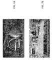
- FIG. 7A shows a large industrial kiln for curing composite parts
- FIG. 7B shows and composite airfoil being worked on
- FIG. 7C is a screenshot of the invention performing a calculation to determine the size and location of compensation plies
- FIG. 7D is a computer screen shot showing how the invention nests the individual plies to minimize material waste
- FIG. 7E is a computer screen shot showing the laser projection technology which draws illuminated shapes to assist in the placing and location of the compensation plies;
- FIG. 8 is a block diagram illustrating the major functional elements of the invention.
- FIG. 9 is a block diagram showing the major architectural components of the ply compensation software.
- FIG. 10 is a block diagram further illustrating the major functional elements of the invention.
- FIG. 11 is a block diagram showing the data flow of the ply compensation program
- FIG. 12 is a computer screen shot showing the compensation ply analysis
- FIG. 13 is a computer screen shot showing the compensation ply layout in a nesting format so as to minimize material waste
- FIG. 14 is a computer screen shot showing the laser projection patterns that will be used to locate and orient the compensation plies as they are laid out on the substandard part;
- FIG. 15 is a computer screen shot illustrating the reporting feature of the invention.
- FIG. 16 is a computer screen shot illustrating a coverage map generated by the invention.
- FIG. 17 is a picture of the laser radar system used to generate a data set which represents the as-built dimensions of the composite part.
- FIG. 18 is a series of photographs showing the invention process.
- a laser radar scans the surface of an as-built part, and creates a three-dimensional data set representing the surface of the as-built part.
- the as-built surface is compared with and against a second data set that represents the as-designed surface.
- a third date is set is created representing the differential dimensions between the as-built surface and the as-designed surface. Any areas which are considered to be out of tolerance are then targeted for ply compensation.
- the software program using parameter inputs such as ply thickness, fiber orientation, stepping protocol, and other parameters for generating the appropriate number and thickness of plies, creates a series of patterns of plies which are to be cut out of a bolt of the ply cloth for layup on the substandard part.
- the nesting software module then takes the series of plies and assembles them into an optimum configuration which when laid out on the ply cloth will minimize material waste.
- the layout configuration may be printed on thin tracing paper for overlay on the ply cloth or alternatively the patterns may be projected onto the cloth for marking and subsequent cut out.
- a laser projection program illuminates trace patterns on the substandard part to identify the location and orientation for placement of the compensation plies.
- the part is then cured a second time in an oven. After curing, the part is once again scanned with laser radar to create a new data set to be compared with the ads designed data set.
- a quality reporting module compares the second as-built data set with the as-designed data set to generate a report showing the final as-built dimensions in compliance with the design specification.
- the first set of inputs is the non-recurring data which is data particular to the design specifications of the part to be built.
- the second set of input data is the data collected by the laser radar representing the as-built dimensions and three-dimensional surface of the part being manufactured.
- the two data sets are compared to determine and locate surface areas that are not within desired tolerances. Those noncompliant areas are then targeted for build up with compensation plies.
- the compensation plies are shaped so as to match, fill and fit into the noncompliant areas of the composite part. Depending upon the depth and shape of the deficiency, one or more plies may be required in a stacking fashion to fill in that area which is non compliant.
- plies are stacked, their perimeter dimension may be incrementally reduced or increased as to create the appropriate three-dimensional shape as required by the design specification.
- Such stacked shaped may be thought of as pyramidal, and depending upon the deficient area, may be right side up or inverted.
- the laser files are modified so as to project the areas where the compensation plies will be applied.
- a multitude of reports are generated to document the manufacturing, surveying, compensation, re-scanning, and final as-built dimensions.
- FIG. 3 shows a particular arrangement of the compensation plies being applied to a deficient part. Note the deficient area being built up on the left-hand side of the part. Several layers of compensation plies are being stacked to bring the composite part within design tolerances. A smaller ply indicated by the red color is stacked upon a larger ply (brown), which is further stacked upon and even larger ply (yellow). This pyramidal stacking brings the substandard part into compliance with the design specification.
- FIG. 4 is a computer screen shot showing how the compensation plies are nested to minimize waste. Note that each ply is labeled with a unique number which will be used to identify its location during placement on to the sub-standard part. Also note how the plies have been arranged so as to minimize wasted material after they have been caught from the cloth.
- FIG. 5 is a computer screen shot showing the trace paths that the laser projection system will draw on the deficient part to assist in the ply layout. These are the locations where the plies will be laid on to the substandard part.
- FIG. 6A shows a block diagram flowchart for the major processes of the invention.
- the software program is critical to the invention as it collects the standard part data and the substandard part data, compares the two data sets to find deficiencies, determines the size and location for compensation plies, automatically nests the plies to minimize waste of material, generates instructions to cut the plies, generates new laser files to project outlines for placing the plies onto the substandard part, and processes the rescan data after the part has been cured to verify final part compliance.
- FIG. 6B is a side elevation view of a composite part showing the application of compensation plies to achieve a nominal surface. Note the composite part's surface is significantly below the nominal surface which creates the substandard part. The dimensional difference between the nominal surface and the composite part surface exceeds the specified tolerance for the final part. Therefore, in those areas where the as-built part is noncompliant, compensation plies will be shaped and designed to fill in these deficient areas. The addition of the compensation plies will raise the finished surface up to the desired nominal surface, and thus the finished part will be within design tolerances.
- FIG. 7A shows a large industrial kiln for curing composite parts. And end cover swings away to open the end of the tubular chamber. Parts to be cured are slid into the oven for a predetermined number of heating cycles.
- FIG. 7B shows a composite airfoil being worked on.
- This horizontal stabilizer is a typical airframe part to which this process may be applied.
- FIG. 7C is a screenshot of the invention performing a calculation to determine the size and location of compensation plies.
- a series of very thin plies are required to compensate.
- Different colors are used by the computer program to indicate the thickness required for compensation.
- the color scheme may be selected and or assigned by the operator.
- FIG. 7D is a computer screen shot showing how the invention nests the individual plies to minimize material waste.
- the nesting program generates the machine code instructions for the CNC machine to perform the cutting operation.
- FIG. 7E is a computer screen shot showing the laser projection technology which draws illuminated shapes to assist in the placing and location of the compensation plies.
- the individual plies may be viewed separately or in a stacked manner.
- FIG. 8 is a block diagram illustrating the major functional elements of the invention.
- FIG. 9 is a block diagram showing the major architectural components of the ply compensation software.
- FIG. 10 is a block diagram further illustrating the major functional elements of the invention.
- FIG. 11 is a block diagram showing the data flow of the ply compensation program.
- FIG. 12 is a computer screen shot showing the compensation ply analysis.
- FIG. 13 is a computer screen shot showing the compensation ply layout in a nesting format so as to minimize material waste.
- FIG. 14 is a computer screen shot showing the laser projection patterns that will be used to locate and orient the compensation plies as they are laid out on the substandard part.
- FIG. 15 is a computer screen shot illustrating the reporting feature of the invention indicating those areas that required ply compensation. Various parameters are recorded and reported such as dimensional data, ply count, discrepancy amount, thickness, location, and orientation (alignment of fibers and/or fabric grain if required).
- FIG. 16 is a computer screen shot illustrating a coverage map generated by the invention.
- the coverage map may be used to generate and or modify laser files to project location information onto the substandard part for the application of compensation plies.
- the coverage map may also be used to generate graphical information for the operator and or to support the reporting functions of the invention.
- FIG. 17 is a picture of the laser radar system used to generate a data set which represents the as-built dimensions of the composite part.
- FIG. 18 is a series of photographs showing the invention process.
Abstract
Description
-
- a) compare the “as-built” composite part data to the “as-designed” specification
- b) determine and identify the zones not within engineering tolerances
- c) calculate the shape and quantity of compensation plies required to build the part into engineering tolerances
- d) automatically nest and cut the compensation plies
- e) automatically generate the laser projection files to position compensation plies accurately
- f) re-cure the composite part
- g) test the finished composite part for compliance with engineering tolerances
-
- a) Compare “As Built” Composite Part to “As Designed”
- b) Determine Zones Out of Engineering Tolerances
- c) Calculate Shape and Quantity of Compensation Plies Required to Build Part Into Engineering Tolerance
- d) Automatically Generate the Nest and NC Code to cut the Compensation Plies
- e) Automatically Generate the Laser Projection Files to Position Compensation Plies Accurately
- f) Automatically Generate Plots and Reports for Statistical Analysis, Cutting and Laser lay-up process.
Claims (20)
Priority Applications (3)
| Application Number | Priority Date | Filing Date | Title |
|---|---|---|---|
| US12/965,786 US9186849B2 (en) | 2009-12-10 | 2010-12-10 | Composite part manufacturing compensation system and method |
| US14/923,222 US10286614B2 (en) | 2009-12-10 | 2015-10-26 | Composite part manufacturing compensation system and method |
| US16/226,884 US11167504B2 (en) | 2009-12-10 | 2018-12-20 | Composite part manufacturing compensation system and method |
Applications Claiming Priority (2)
| Application Number | Priority Date | Filing Date | Title |
|---|---|---|---|
| US28519109P | 2009-12-10 | 2009-12-10 | |
| US12/965,786 US9186849B2 (en) | 2009-12-10 | 2010-12-10 | Composite part manufacturing compensation system and method |
Related Child Applications (1)
| Application Number | Title | Priority Date | Filing Date |
|---|---|---|---|
| US14/923,222 Continuation US10286614B2 (en) | 2009-12-10 | 2015-10-26 | Composite part manufacturing compensation system and method |
Publications (2)
| Publication Number | Publication Date |
|---|---|
| US20150165674A1 US20150165674A1 (en) | 2015-06-18 |
| US9186849B2 true US9186849B2 (en) | 2015-11-17 |
Family
ID=53367326
Family Applications (3)
| Application Number | Title | Priority Date | Filing Date |
|---|---|---|---|
| US12/965,786 Active 2031-05-16 US9186849B2 (en) | 2009-12-10 | 2010-12-10 | Composite part manufacturing compensation system and method |
| US14/923,222 Active 2032-05-27 US10286614B2 (en) | 2009-12-10 | 2015-10-26 | Composite part manufacturing compensation system and method |
| US16/226,884 Active 2030-12-13 US11167504B2 (en) | 2009-12-10 | 2018-12-20 | Composite part manufacturing compensation system and method |
Family Applications After (2)
| Application Number | Title | Priority Date | Filing Date |
|---|---|---|---|
| US14/923,222 Active 2032-05-27 US10286614B2 (en) | 2009-12-10 | 2015-10-26 | Composite part manufacturing compensation system and method |
| US16/226,884 Active 2030-12-13 US11167504B2 (en) | 2009-12-10 | 2018-12-20 | Composite part manufacturing compensation system and method |
Country Status (1)
| Country | Link |
|---|---|
| US (3) | US9186849B2 (en) |
Families Citing this family (6)
| Publication number | Priority date | Publication date | Assignee | Title |
|---|---|---|---|---|
| FR3045450A1 (en) * | 2015-12-21 | 2017-06-23 | Plastic Omnium Cie | IMPROVED MANUFACTURING METHOD OF A MOTOR VEHICLE PART |
| WO2017204945A1 (en) * | 2016-05-26 | 2017-11-30 | Ocv Intellectual Capital, Llc | System for making fibre-reinforcing materials for structural components |
| US11007727B2 (en) | 2017-12-29 | 2021-05-18 | Tpi Composites, Inc. | Semi-automated layup process for fabrication of wind turbine blades using laser projection system |
| US11181887B2 (en) * | 2018-12-14 | 2021-11-23 | The Boeing Company | Predictive surface adjustment for joint assembly |
| FR3102281B1 (en) * | 2019-10-21 | 2021-11-05 | Airbus | Method and system for optimizing the arrangement of a set of aircraft parts on a plate |
| DE102019132346B4 (en) * | 2019-11-28 | 2021-12-16 | Lufthansa Technik Aktiengesellschaft | Device for the positioning of fluid dynamically functional foils and their use |
Citations (17)
| Publication number | Priority date | Publication date | Assignee | Title |
|---|---|---|---|---|
| US4848137A (en) * | 1988-03-23 | 1989-07-18 | The Boeing Company | Automated shim manufacturing system |
| US5341183A (en) * | 1992-09-28 | 1994-08-23 | The Boeing Company | Method for controlling projection of optical layup template |
| US5450147A (en) * | 1992-09-28 | 1995-09-12 | The Boeing Company | Method for controlling projection of optical layup template utilizing cooperative targets |
| US5651600A (en) * | 1992-09-28 | 1997-07-29 | The Boeing Company | Method for controlling projection of optical layup template utilizing cooperative targets |
| US6000801A (en) * | 1997-05-02 | 1999-12-14 | General Scanning, Inc. | Multi-color laser projector for optical layup template and the like |
| US20010046323A1 (en) * | 2000-03-09 | 2001-11-29 | The Boeing Company | Method, apparatus and computer program product for determining shim shape |
| US6547397B1 (en) * | 2000-04-19 | 2003-04-15 | Laser Projection Technologies, Inc. | Apparatus and method for projecting a 3D image |
| US20030090025A1 (en) * | 2001-11-13 | 2003-05-15 | Nelson Karl M. | Resin transfer molding multi-part/shim tooling (RTM-MPST) |
| US20040217497A1 (en) * | 2003-05-02 | 2004-11-04 | The Boeing Company | Triple purpose lay-up tool |
| US6843565B2 (en) * | 2002-08-02 | 2005-01-18 | General Electric Company | Laser projection system to facilitate layup of complex composite shapes |
| US20050082262A1 (en) * | 2003-09-10 | 2005-04-21 | Rueb Kurt D. | Laser projection systems and methods |
| US6907651B1 (en) * | 1999-08-21 | 2005-06-21 | Bae Systems Plc | Manufacturing and assembly of structures using shims |
| US20060191622A1 (en) * | 2005-02-28 | 2006-08-31 | The Boeing Company | Real-time infrared thermography inspection and control for automated composite material layup |
| US7241981B2 (en) * | 2004-03-05 | 2007-07-10 | Lap Laser Llc | Systems and methods for displaying images and processing work pieces |
| US7268893B2 (en) * | 2004-11-12 | 2007-09-11 | The Boeing Company | Optical projection system |
| US20080164376A1 (en) * | 2006-11-20 | 2008-07-10 | Honda Motor Co., Ltd. | Leading edge skin height difference adjusting structure and method of assembling leading edge skin |
| US20100112190A1 (en) * | 2008-11-04 | 2010-05-06 | Drewett Jeffrey T | Composite laminate thickness compensation |
Family Cites Families (10)
| Publication number | Priority date | Publication date | Assignee | Title |
|---|---|---|---|---|
| US5088047A (en) * | 1989-10-16 | 1992-02-11 | Bynum David K | Automated manufacturing system using thin sections |
| US7463368B2 (en) * | 2003-09-10 | 2008-12-09 | Metris Canada Inc | Laser projection system, intelligent data correction system and method |
| US20070193655A1 (en) * | 2006-02-07 | 2007-08-23 | Columbia Forest Products, Inc. | Extraction of non-contiguous component panels from a panel |
| GB0910938D0 (en) * | 2009-06-25 | 2009-08-05 | Airbus Operations Ltd | Method of manufacturing a structure |
| US20130066601A1 (en) * | 2011-09-13 | 2013-03-14 | CGN & Associates, Inc. | Product attribute visualizer |
| US20140261970A1 (en) * | 2013-03-15 | 2014-09-18 | General Electric Company | Method of making a laminate component and method of removing voids from a pre-preg ply and a pre-preg component |
| JP6356339B2 (en) * | 2015-08-11 | 2018-07-11 | サビック グローバル テクノロジーズ ビー.ブイ. | Multi-ply laminated composites with low unit area weight |
| US10322792B2 (en) * | 2016-02-08 | 2019-06-18 | The Boeing Company | Ply optimization feasibility analysis for multi-layer composite parts |
| US10380319B2 (en) * | 2016-02-08 | 2019-08-13 | The Boeing Company | Sublaminate library generation for optimization of multi-panel composite parts |
| EP3581884A1 (en) * | 2018-06-15 | 2019-12-18 | Hexagon Technology Center GmbH | Additive manufacturing with optical process monitoring |
-
2010
- 2010-12-10 US US12/965,786 patent/US9186849B2/en active Active
-
2015
- 2015-10-26 US US14/923,222 patent/US10286614B2/en active Active
-
2018
- 2018-12-20 US US16/226,884 patent/US11167504B2/en active Active
Patent Citations (17)
| Publication number | Priority date | Publication date | Assignee | Title |
|---|---|---|---|---|
| US4848137A (en) * | 1988-03-23 | 1989-07-18 | The Boeing Company | Automated shim manufacturing system |
| US5341183A (en) * | 1992-09-28 | 1994-08-23 | The Boeing Company | Method for controlling projection of optical layup template |
| US5450147A (en) * | 1992-09-28 | 1995-09-12 | The Boeing Company | Method for controlling projection of optical layup template utilizing cooperative targets |
| US5651600A (en) * | 1992-09-28 | 1997-07-29 | The Boeing Company | Method for controlling projection of optical layup template utilizing cooperative targets |
| US6000801A (en) * | 1997-05-02 | 1999-12-14 | General Scanning, Inc. | Multi-color laser projector for optical layup template and the like |
| US6907651B1 (en) * | 1999-08-21 | 2005-06-21 | Bae Systems Plc | Manufacturing and assembly of structures using shims |
| US20010046323A1 (en) * | 2000-03-09 | 2001-11-29 | The Boeing Company | Method, apparatus and computer program product for determining shim shape |
| US6547397B1 (en) * | 2000-04-19 | 2003-04-15 | Laser Projection Technologies, Inc. | Apparatus and method for projecting a 3D image |
| US20030090025A1 (en) * | 2001-11-13 | 2003-05-15 | Nelson Karl M. | Resin transfer molding multi-part/shim tooling (RTM-MPST) |
| US6843565B2 (en) * | 2002-08-02 | 2005-01-18 | General Electric Company | Laser projection system to facilitate layup of complex composite shapes |
| US20040217497A1 (en) * | 2003-05-02 | 2004-11-04 | The Boeing Company | Triple purpose lay-up tool |
| US20050082262A1 (en) * | 2003-09-10 | 2005-04-21 | Rueb Kurt D. | Laser projection systems and methods |
| US7241981B2 (en) * | 2004-03-05 | 2007-07-10 | Lap Laser Llc | Systems and methods for displaying images and processing work pieces |
| US7268893B2 (en) * | 2004-11-12 | 2007-09-11 | The Boeing Company | Optical projection system |
| US20060191622A1 (en) * | 2005-02-28 | 2006-08-31 | The Boeing Company | Real-time infrared thermography inspection and control for automated composite material layup |
| US20080164376A1 (en) * | 2006-11-20 | 2008-07-10 | Honda Motor Co., Ltd. | Leading edge skin height difference adjusting structure and method of assembling leading edge skin |
| US20100112190A1 (en) * | 2008-11-04 | 2010-05-06 | Drewett Jeffrey T | Composite laminate thickness compensation |
Also Published As
| Publication number | Publication date |
|---|---|
| US20150165674A1 (en) | 2015-06-18 |
| US20160121556A1 (en) | 2016-05-05 |
| US20190118494A1 (en) | 2019-04-25 |
| US11167504B2 (en) | 2021-11-09 |
| US10286614B2 (en) | 2019-05-14 |
Similar Documents
| Publication | Publication Date | Title |
|---|---|---|
| US11167504B2 (en) | Composite part manufacturing compensation system and method | |
| US11554556B2 (en) | Optimization of layup process for fabrication of wind turbine blades using model-based optical projection system | |
| US9156240B2 (en) | Automated production and installation of patches for reworking structures | |
| Akande | Dimensional accuracy and surface finish optimization of fused deposition modelling parts using desirability function analysis | |
| US9993971B2 (en) | Fitting doublers using gap mapping | |
| JP2551677B2 (en) | How to generate a computerized ply pattern | |
| CN107672180B (en) | A kind of 3D printing accuracy checking method based on reverse Engineering Technology | |
| US20180297115A1 (en) | Real Time Detection of Defects during Formation of an Additively Manufactured Component | |
| CN105437543A (en) | Three-dimensional printing device and coordinate deviation compensation method of spray head thereof | |
| CN105058795A (en) | Error compensating method for material-increase manufacturing | |
| US20110290421A1 (en) | Automatic system for quality control and position correction of taped parts | |
| US20010023543A1 (en) | Conformance gauge | |
| EP3658316A1 (en) | Method for modifying components using additive manufacturing | |
| US20070042327A1 (en) | Determination of scaling for scaled physical architectural models | |
| WO2021076115A1 (en) | Generation of modified model data for three-dimensional printers | |
| Singh | An overview of three dimensional printing for casting applications | |
| US10875271B2 (en) | Gap fillers for composite materials | |
| Ituarte et al. | Post-processing opportunities of professional and consumer grade 3D printing equipment: a comparative study | |
| Spillane et al. | A Voxel-Based Design Approach for Creating Functionally Graded Structures Via Material Extrusion Additive Manufacturing | |
| Krauze | MoDern Process of coMPosite structures ManufacturinG BaseD on caD Definition of the coMPosite | |
| RU2419541C1 (en) | Device to produce multilayer blank for fabrication of laminar articles | |
| Sirinterlikci et al. | 3D Printing Pre-processing | |
| James | LAMINATE DESIGN METHODS FOR CLOSED VOLUME STRUCTURES | |
| Nehro | Using 3D Printing to Build Flight-Certified Hardware | |
| Cassola Camps | Manufacturing parameters characterisation of 3D printer |
Legal Events
| Date | Code | Title | Description |
|---|---|---|---|
| AS | Assignment |
Owner name: MAGESTIC SYSTEMS INCORPORATED, NEW JERSEY Free format text: ASSIGNMENT OF ASSIGNORS INTEREST;ASSIGNORS:MACLEAN, GREGORY;SPELLMAN, MICHAEL;GODFREY, JEFF;SIGNING DATES FROM 20140616 TO 20140617;REEL/FRAME:033127/0423 |
|
| STCF | Information on status: patent grant |
Free format text: PATENTED CASE |
|
| AS | Assignment |
Owner name: AUTODESK, INC., CALIFORNIA Free format text: ASSIGNMENT OF ASSIGNORS INTEREST;ASSIGNOR:MAGESTIC SYSTEMS INC.;REEL/FRAME:037598/0286 Effective date: 20151026 |
|
| MAFP | Maintenance fee payment |
Free format text: PAYMENT OF MAINTENANCE FEE, 4TH YEAR, LARGE ENTITY (ORIGINAL EVENT CODE: M1551); ENTITY STATUS OF PATENT OWNER: LARGE ENTITY Year of fee payment: 4 |
|
| MAFP | Maintenance fee payment |
Free format text: PAYMENT OF MAINTENANCE FEE, 8TH YEAR, LARGE ENTITY (ORIGINAL EVENT CODE: M1552); ENTITY STATUS OF PATENT OWNER: LARGE ENTITY Year of fee payment: 8 |