US9187004B1 - Electric vehicle carousel battery exchange/charging system - Google Patents
Electric vehicle carousel battery exchange/charging system Download PDFInfo
- Publication number
- US9187004B1 US9187004B1 US14/678,341 US201514678341A US9187004B1 US 9187004 B1 US9187004 B1 US 9187004B1 US 201514678341 A US201514678341 A US 201514678341A US 9187004 B1 US9187004 B1 US 9187004B1
- Authority
- US
- United States
- Prior art keywords
- battery
- transportation platform
- carousel
- charged
- depleted
- Prior art date
- Legal status (The legal status is an assumption and is not a legal conclusion. Google has not performed a legal analysis and makes no representation as to the accuracy of the status listed.)
- Expired - Fee Related
Links
- 238000000429 assembly Methods 0.000 claims description 2
- 230000000712 assembly Effects 0.000 claims description 2
- 238000003780 insertion Methods 0.000 abstract description 2
- 230000037431 insertion Effects 0.000 abstract description 2
- 229910000831 Steel Inorganic materials 0.000 description 35
- 239000010959 steel Substances 0.000 description 35
- 238000000034 method Methods 0.000 description 9
- 238000009434 installation Methods 0.000 description 6
- 230000009977 dual effect Effects 0.000 description 3
- 238000007792 addition Methods 0.000 description 2
- 238000000151 deposition Methods 0.000 description 2
- 238000005516 engineering process Methods 0.000 description 2
- 238000013459 approach Methods 0.000 description 1
- 230000010267 cellular communication Effects 0.000 description 1
- 238000012217 deletion Methods 0.000 description 1
- 230000037430 deletion Effects 0.000 description 1
- 239000000284 extract Substances 0.000 description 1
- 230000005484 gravity Effects 0.000 description 1
- 238000012986 modification Methods 0.000 description 1
- 230000004048 modification Effects 0.000 description 1
- 230000000284 resting effect Effects 0.000 description 1
- 238000005096 rolling process Methods 0.000 description 1
- 238000006467 substitution reaction Methods 0.000 description 1
- 230000001360 synchronised effect Effects 0.000 description 1
- 230000007704 transition Effects 0.000 description 1
- 238000004804 winding Methods 0.000 description 1
Images


Classifications
-
- B—PERFORMING OPERATIONS; TRANSPORTING
- B60—VEHICLES IN GENERAL
- B60L—PROPULSION OF ELECTRICALLY-PROPELLED VEHICLES; SUPPLYING ELECTRIC POWER FOR AUXILIARY EQUIPMENT OF ELECTRICALLY-PROPELLED VEHICLES; ELECTRODYNAMIC BRAKE SYSTEMS FOR VEHICLES IN GENERAL; MAGNETIC SUSPENSION OR LEVITATION FOR VEHICLES; MONITORING OPERATING VARIABLES OF ELECTRICALLY-PROPELLED VEHICLES; ELECTRIC SAFETY DEVICES FOR ELECTRICALLY-PROPELLED VEHICLES
- B60L53/00—Methods of charging batteries, specially adapted for electric vehicles; Charging stations or on-board charging equipment therefor; Exchange of energy storage elements in electric vehicles
- B60L53/30—Constructional details of charging stations
-
- B60L11/1822—
-
- B60L11/1824—
-
- B—PERFORMING OPERATIONS; TRANSPORTING
- B60—VEHICLES IN GENERAL
- B60L—PROPULSION OF ELECTRICALLY-PROPELLED VEHICLES; SUPPLYING ELECTRIC POWER FOR AUXILIARY EQUIPMENT OF ELECTRICALLY-PROPELLED VEHICLES; ELECTRODYNAMIC BRAKE SYSTEMS FOR VEHICLES IN GENERAL; MAGNETIC SUSPENSION OR LEVITATION FOR VEHICLES; MONITORING OPERATING VARIABLES OF ELECTRICALLY-PROPELLED VEHICLES; ELECTRIC SAFETY DEVICES FOR ELECTRICALLY-PROPELLED VEHICLES
- B60L53/00—Methods of charging batteries, specially adapted for electric vehicles; Charging stations or on-board charging equipment therefor; Exchange of energy storage elements in electric vehicles
- B60L53/80—Exchanging energy storage elements, e.g. removable batteries
-
- B—PERFORMING OPERATIONS; TRANSPORTING
- B60—VEHICLES IN GENERAL
- B60S—SERVICING, CLEANING, REPAIRING, SUPPORTING, LIFTING, OR MANOEUVRING OF VEHICLES, NOT OTHERWISE PROVIDED FOR
- B60S5/00—Servicing, maintaining, repairing, or refitting of vehicles
- B60S5/06—Supplying batteries to, or removing batteries from, vehicles
-
- H—ELECTRICITY
- H01—ELECTRIC ELEMENTS
- H01M—PROCESSES OR MEANS, e.g. BATTERIES, FOR THE DIRECT CONVERSION OF CHEMICAL ENERGY INTO ELECTRICAL ENERGY
- H01M10/00—Secondary cells; Manufacture thereof
- H01M10/42—Methods or arrangements for servicing or maintenance of secondary cells or secondary half-cells
- H01M10/425—Structural combination with electronic components, e.g. electronic circuits integrated to the outside of the casing
- H01M2010/4278—Systems for data transfer from batteries, e.g. transfer of battery parameters to a controller, data transferred between battery controller and main controller
-
- H—ELECTRICITY
- H01—ELECTRIC ELEMENTS
- H01M—PROCESSES OR MEANS, e.g. BATTERIES, FOR THE DIRECT CONVERSION OF CHEMICAL ENERGY INTO ELECTRICAL ENERGY
- H01M2220/00—Batteries for particular applications
- H01M2220/20—Batteries in motive systems, e.g. vehicle, ship, plane
-
- Y—GENERAL TAGGING OF NEW TECHNOLOGICAL DEVELOPMENTS; GENERAL TAGGING OF CROSS-SECTIONAL TECHNOLOGIES SPANNING OVER SEVERAL SECTIONS OF THE IPC; TECHNICAL SUBJECTS COVERED BY FORMER USPC CROSS-REFERENCE ART COLLECTIONS [XRACs] AND DIGESTS
- Y02—TECHNOLOGIES OR APPLICATIONS FOR MITIGATION OR ADAPTATION AGAINST CLIMATE CHANGE
- Y02E—REDUCTION OF GREENHOUSE GAS [GHG] EMISSIONS, RELATED TO ENERGY GENERATION, TRANSMISSION OR DISTRIBUTION
- Y02E60/00—Enabling technologies; Technologies with a potential or indirect contribution to GHG emissions mitigation
- Y02E60/10—Energy storage using batteries
-
- Y—GENERAL TAGGING OF NEW TECHNOLOGICAL DEVELOPMENTS; GENERAL TAGGING OF CROSS-SECTIONAL TECHNOLOGIES SPANNING OVER SEVERAL SECTIONS OF THE IPC; TECHNICAL SUBJECTS COVERED BY FORMER USPC CROSS-REFERENCE ART COLLECTIONS [XRACs] AND DIGESTS
- Y02—TECHNOLOGIES OR APPLICATIONS FOR MITIGATION OR ADAPTATION AGAINST CLIMATE CHANGE
- Y02T—CLIMATE CHANGE MITIGATION TECHNOLOGIES RELATED TO TRANSPORTATION
- Y02T10/00—Road transport of goods or passengers
- Y02T10/60—Other road transportation technologies with climate change mitigation effect
- Y02T10/70—Energy storage systems for electromobility, e.g. batteries
-
- Y—GENERAL TAGGING OF NEW TECHNOLOGICAL DEVELOPMENTS; GENERAL TAGGING OF CROSS-SECTIONAL TECHNOLOGIES SPANNING OVER SEVERAL SECTIONS OF THE IPC; TECHNICAL SUBJECTS COVERED BY FORMER USPC CROSS-REFERENCE ART COLLECTIONS [XRACs] AND DIGESTS
- Y02—TECHNOLOGIES OR APPLICATIONS FOR MITIGATION OR ADAPTATION AGAINST CLIMATE CHANGE
- Y02T—CLIMATE CHANGE MITIGATION TECHNOLOGIES RELATED TO TRANSPORTATION
- Y02T10/00—Road transport of goods or passengers
- Y02T10/60—Other road transportation technologies with climate change mitigation effect
- Y02T10/7072—Electromobility specific charging systems or methods for batteries, ultracapacitors, supercapacitors or double-layer capacitors
-
- Y—GENERAL TAGGING OF NEW TECHNOLOGICAL DEVELOPMENTS; GENERAL TAGGING OF CROSS-SECTIONAL TECHNOLOGIES SPANNING OVER SEVERAL SECTIONS OF THE IPC; TECHNICAL SUBJECTS COVERED BY FORMER USPC CROSS-REFERENCE ART COLLECTIONS [XRACs] AND DIGESTS
- Y02—TECHNOLOGIES OR APPLICATIONS FOR MITIGATION OR ADAPTATION AGAINST CLIMATE CHANGE
- Y02T—CLIMATE CHANGE MITIGATION TECHNOLOGIES RELATED TO TRANSPORTATION
- Y02T90/00—Enabling technologies or technologies with a potential or indirect contribution to GHG emissions mitigation
- Y02T90/10—Technologies relating to charging of electric vehicles
- Y02T90/12—Electric charging stations
Abstract
A system providing a driver of an electric vehicle with the ability to exchange a depleted battery with a charged battery. Information regarding the status of an electric battery is transmitted to service stations, and information is returned to a driver indicating the location of a service station with a charged battery. The driver enters the station and is automatically positioned next to a rotating carousel. A robotic arm removes the depleted battery from the vehicle and pulls it onto the carousel, which rotates and deposits the battery onto a return conveyor belt, which carries the battery to a transportation platform for movement to a battery rack for charging. The transportation platform removes a charged battery from the battery rack and carries it to an outgoing conveyor belt, which carries it to the carousel, which rotates until the battery is next to the vehicle for insertion by the robotic arm.
Description
The present invention relates to a system that can be implemented in roadside stations to enable owners of electrically-powered vehicles to exchange depleted or discharged batteries with charged batteries, thereby improving their mobility.
The widespread adoption of vehicles powered by electrical batteries has been impeded by their limited mobility. An owner can use an electrically-powered vehicle (hereinafter “electric vehicle”) to drive to work, to shop, and to perform errands, but he must keep in mind his distance from his power source, which is typically his garage. The vehicle's battery is plugged into the home's power source in the evening so that it can be charged overnight. While the vehicle serves its purpose for commuting and for local trips, presently it cannot be depended upon by a driver to use when driving long distances or when taking a vacation away from home.
A need exists for roadside stations which enable the owner of an electrical vehicle to exchange his vehicle's discharged or depleted batteries with charged batteries, in a short amount of time.
The present invention is designed to increase the popularity of electric vehicles by providing their owners with unlimited mobility, security and confidence, namely by providing service stations that will keep the batteries in their vehicles charged at all times.1 1Presently, manufacturers use stationary batteries in their electrically-powered vehicles. The present invention anticipates the move to portable electrical batteries or battery modules.
The present invention envisions a network of service stations that will be conveniently located on highways. Current wireless technology can be used to monitor an electrical battery's power level as it discharges and to locate nearby service stations. When the battery reaches a pre-determined “low” level, the driver will be alerted to stop at a service station to exchange the battery for a charged batter. Ideally, the information regarding the vehicle's make and model and its particular battery is transmitted to the service station, so that the automated system can come into play to implement the battery exchange process.
When the driver reaches the service station, he will be instructed to enter a particular lane and drive onto a track conveyor. The automated process positions the vehicle on the conveyor, which carries the vehicle to the carousel station. The driver releases the cover of the battery compartment, and a robotic arm extracts the depleted battery from the compartment, pulling it out onto the carousel. The carousel then rotates to the next position, where a charged battery has been conveyed by the process described infra. The robotic arm pushes the battery into the empty battery compartment. The process is repeated if there is more than one battery to be exchanged. After the battery or batteries have been exchanged, the vehicle is conveyed to the exit lane, and the driver closes the cover of the battery compartment and exits the service station.
The process for selecting and delivering the correct battery to the vehicle is also an automated process. A computer will receive the information transmitted by the electrically-powered vehicle regarding the type of vehicle and battery. The computer will direct the movements of an overhead crane, which will select a battery platform and secure it in place by lowering it into a pin and eyelet. A robotic arm pulls the correct battery from its charging compartment onto the platform. The platform with the battery will be transported to an out-going gravity conveyor. The battery reaches the conveyor belt, which will transport the battery to its position on the carousel, where a robotic arm will place it into the battery compartment of the waiting vehicle.
An object of the present invention is to increase the public's demand for using electric vehicles.
Another object of the present invention is to provide owners of electric vehicles with the ability to exchange their vehicles' depleted electrical batteries, no matter what size or type, for charged electrical batteries.
Yet another object of the present invention is to provide service stations that can process the battery exchanges in as little time as the task of re-fueling a vehicle's gas tank, making such exchanges both easy and convenient.
A still further object of the present invention is to provide service stations that can charge depleted batteries so that they are ready for reinstallation into another electric vehicle.
One more object of the present invention is to provide a system and service stations which can be conveniently located on highways, thereby improving the mobility of electric vehicles.
The system of the present invention is designed to incorporate a linear movement of a depleted battery from the time it is removed from a vehicle until the time, after re-charging, that it is re-introduced into a similar electric vehicle.
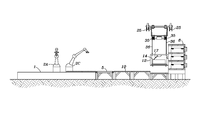
As shown in FIG. 1 , the exchange/charging system of the present invention comprises a horizontal, circular, rotating carousel 1 with an even number of rectangular roller conveyor sections 7 (here shown as 7A, 7B, 7C, 7D, 7E, 7F, 7G, 7H, 71, 7J, 7K, and 7L). A stationary circular platform 6 supports several pedestals 4 (here 4A, 4B, and 4C), each of which holds a robotic/mechanical arm 2 (here 2A, 2B, and 2C). There will be three or four robotic/mechanical arms 2, depending on the configuration of the system. The robotic/mechanical arms 2 are used to either remove or install a battery 14 from or into an electric vehicle 13, using its blade 3 (here 3A, 3B, and 3C), which is inserted into the slot 15 of the battery 14. The batteries 14 are transported between the transportation platform landing area 11 and the carousel 1 on curved, roller-type, gravity-actuated, conveyor belts (here 9, 10), each having a belt-driven section 5 that insures that the transportation platform landing area 11 and a particular conveyor section 7 on the carousel 1 are properly positioned before the battery 14 moves onto one or the other.
In operation, a vehicle 13 will stop next to the carousel 1 at roller conveyor section 7A. The robotic/mechanical arm 2A reaches out and removes the depleted battery 14 from the vehicle 13, depositing it onto empty roller conveyor section 7A of the carousel 1. The carousel 1 advances and the robotic/mechanical arm 2B pushes the depleted battery 14 onto the return conveyor belt 9, where it glides up to and then onto the motorized belt-driven section 5. When the transportation platform 12, reaches the transportation platform landing area 11, the battery 14 is transferred to the transportation platform 12. The transportation platform 12 lifts the battery 14 and aligns it with the designated empty battery-charging module 30, and the battery 14 is deposited into the designated battery charging module 30. The transportation platform 12 then aligns with a charged battery 14, which is moved onto the transportation platform 12 and taken to the outgoing transportation platform landing area 11, where the charged battery 14 is slid off onto the outgoing conveyor belt 10. When the battery 14 arrives at the carousel 1, the robotic/mechanical arm 2C reaches out and pulls the battery 14 onto the carousel 1. Meanwhile the transportation platform 12 traverses the width of the building, returning to the return conveyor belt 9, transportation platform landing area 11. The carousel 1 advances until the correct charged battery 14 is aligned with the vehicle, and a robotic arm 2 installs the battery 14. The vehicle 13 drives away and the next vehicle pulls into the space vacated by the previous vehicle 13 and the process starts again with this vehicle. This simple system is designed for speed, efficiency and completely automated operation.
In FIG. 3 , the blade 3 of a robotic/mechanical arm 2 has been inserted into the slot 15 of a charged battery 14 located on the outgoing conveyor belt 10, and the robotic arm 2 will pull the battery 14 onto a conveyor section 7 of the carousel 1 with the assistance of the motorized belt-driven section 5.
As shown in FIG. 4 , the depleted battery 14 is being pushed onto the transportation platform 12 with the assistance of the motorized belt-driven section 5, and the blade 37 of the ceiling-mounted robotic/mechanical arm 17 is being inserted into a slot 38 in the battery 14 to pull or lift the battery 14 onto the transportation platform 12.
As shown in FIG. 5 , once the depleted battery 14 is positioned on the transportation platform 12, the transportation platform 12 will carry the depleted battery 14 to a predetermined battery charging module 30 and, using a pushing motion, the robotic/mechanical arm 17 will deposit the depleted battery 14 into the appropriate battery charging module 30.
As shown in FIG. 6 , after depositing the depleted battery 14 into the battery charging module 30, the transportation platform 12 will then move to the next predetermined battery charging module 30 and the robotic/mechanical arm 17 will remove the charged battery 14 from the battery charging module 30 with a pulling motion and deposit the charged battery 14 onto the transportation platform 12.
Once the transportation platform 12 is positioned at the transportation platform landing area 11, a charged battery 14 will be pushed onto the outgoing gravity-motivated conveyor belt 10 by the robotic/mechanical arm 17, as shown in FIG. 8 .
As shown in FIG. 9 , the blade 3 of the robotic/mechanical arm 2 has been inserted into the slot 15 of the depleted battery 14 resting on a conveyor section 7 on the carousel 1, directly aligned with the return conveyor belt 9. The arm 2 pushes the battery 14 onto the return conveyor belt 9, where it will slowly glide towards the battery rack 8.
Referring to FIG. 10 and FIG. 11 , the transportation platform 12 is designed to travel horizontally on the two I-beams 25 alongside the battery rack 8 (not shown). The upper portion of the transportation platform 12 has four steel wheels 26 with bearings. Each pair of wheels 26 is attached to a round steel bar axle 24, with a collar 27 on either side of each wheel 26. Below the axles 24, a first steel plate 20A is attached by eight U-bolts 23, four pairs of two each, to the axles 24. Welded to the underside of the first steel plate 20A are two steel angle pieces 22A, one along each edge. The upper portions of four vertical steel bars 21 are welded to the steel angle pieces 22. A second steel plate 20B forming the bottom of the upper portion of the transportation platform 12 is welded to steel angle pieces 22B. The lower portion of vertical steel bars 21 are welded to steel angles 22B, to complete the upper portion of the transportation platform 12.
Welded to the underside of the second steel plate 20B are two dual drum winches 35. Attached to each of the four winch cables 36 is a steel hook 29, which is attached to a steel eyelet 28 (see detail FIG. 10A ) that has been welded to the upperside of a third steel plate 20C. Welded horizontally to the underside of the third steel plate 20C are two steel angles 22C, one along each edge. The upper portion of the vertical steel bars 21 are welded to the steel angle pieces 22C. A fourth steel plate 20D forming the bottom of the lower portion of the transportation platform 12 is welded to steel angle pieces 22D. The lower portion of the vertical steel bars 21 are welded to steel angle pieces 22D, to complete the lower portion of the transportation platform 12.
A single roller conveyor section 40 has been welded onto the upperside of the fourth steel plate 20D in order to assist in the placement of the battery 14 (not shown). The arm support 39 of the ceiling-mounted robotic/mechanical arm 17 has been welded to the underside of the third steel plate 20C as shown in FIG. 10 and FIG. 11 . The robotic/mechanical arm 17 will be used for the installation/removal of the batteries 14 to and from the transportation platform 12.
The transportation platform 12 incorporates two electromagnets 16, each one attached to a steel bar 21, facing the battery rack 8. The electromagnets 16 will be energized once the transportation platform 12 is positioned in front of the battery charging module 30 into or out of which the battery 14 is to be installed or removed (not shown) in order to stabilize the movement of the transportation platform 12.
The alignment of the transportation platform 12 at the transportation platform landing area 11 is accomplished using four pins 18, each of which will be inserted into a pre-drilled hole 41 in the steel plate 46 of the transportation platform landing area support 34, as shown in FIG. 11A . This section can be reinforced using steel bar supports. The transportation platform landing area support 34 will be recessed in order for the transportation platform 12 to align properly with the return conveyor belt 9 and the outgoing conveyor belt 10.
As shown in FIG. 12 and FIG. 13 , the battery rack 8 is constructed from horizontal I-beams 42 welded to vertical I-beam support columns 43. The battery rack 8 will run the width of the building between the transportation platform landing areas 11, as shown in FIG. 13 . Welded between the support columns 43 and connecting them are plate steel panels 44. Battery charging modules 30 are placed along the plate steel panels 44 and secured; they provide a place for the batteries 14 to receive a charge. (The battery charging systems will be supplied by the manufacturers of the batteries.) The battery rack 8 will be capable of charging all electric vehicle batteries, regardless of their size. The battery charging module 30 depicts a front and overhead view of a normal battery charging module 30. The battery charging module 30A is designed for charging a smaller-sized battery, with an insert 45 specifically designed to allow for charging any size battery 14; it insures that the battery charging module 30A maintains the proper alignment for use with the transportation platform 12, as shown in FIG. 12 .
The transportation platform 12 will be driven using a DC motor 19 affixed to a sprocket 31 and chain 32. The chain 32 will be welded to the upper steel plate 20A (not visible in this view) of the transportation platform 12 and looped around an adjacent sprocket 31 at the other end of the battery rack 8, as shown in FIG. 13 . To insure that the chain 32 maintains the proper tension, a chain tensioner 33 will be incorporated.
As seen in FIG. 14 and FIG. 15 , the carousel 1 makes it possible to exchange batteries 14 quickly and efficiently. The carousel 1 will be supported using a steel plate platform 50 welded to an I-beam support frame 51, as shown in FIG. 14 . The carousel 1 will ride on roller bearing assembly 52 consisting of two pieces, the roller bearing ring 53 and the bearing race ring 54. The roller bearing ring 53 will be welded to the underside of the carousel 1, and the bearing race ring 54 will be welded to the topside of the steel plate platform 50, as shown in FIG. 15 . The carousel 1 will require two roller bearing assemblies 52, one at its outer diameter and one at the inner diameter. The carousel 1 will be driven by a DC motor 60 fitted with a sprocket 61 and inserted into a chain 62 welded to the outside circumference of the carousel's steel plate platform plate 50, as shown in FIG. 14 . The support for the DC motor 60 will be an I-beam support column 63 welded to a steel angle mounting bracket 64, as shown in FIG. 15 .
To insure that the batteries 14 are properly aligned during the complete process, guides can be incorporated at every transition point so that the positioning of the battery 14 will remain exact, as shown in FIG. 16 .
Owners of electric battery vehicles can plan to take long automobile trips using Wi-Fi and GPS technology, and relying on the exchange stations utilizing the battery exchange system of the present invention. At the beginning of the trip, the battery is fully charge. The vehicle's computer monitors the battery level and is in constant cellular communications with all the surrounding exchange stations along the route. After approximately 225 miles, the vehicle's computer alerts the driver that the battery has 25% capacity remaining. The driver has no concerns because the computer has also notified him of all the stations within the area that have a fully charged battery for his vehicle. Once the driver makes his choice, the GPS directs the driver to the appropriate station. As the driver approaches the station, the computer directs the driver to the lane in which he will enter for the battery exchange to take place. The appropriate battery has already been pulled from the charging rack, and, as the automobile pulls up to the exchange carousel, the driver's battery is the next in line. The robotic arm whisks away the depleted battery and installs the fully-charged battery in a matter of minutes, and, for a small fee the driver pulls away. If, for some reason, a fully-charged battery was not available, the depleted battery would be exchanged with a partially-charged one, approximately 75% to 90% capacity, and the fee would reflect this. The driver could complete his journey with little or no inconvenience. Because the system of the present invention is designed to be fully automated, stations would never need to be closed and, in case of power failure, a backup generator would suffice. When planning his trip, a driver could book hotel reservations at a hotel with charging terminals so as to avoid having to worry about having his vehicle's battery charged for local travel. The next morning the battery would be fully charged.
Although the present invention has been described with reference to preferred embodiments, it will be understood by those skilled in the art that additions, modifications, substitutions, deletions and other changes not specifically described are possible, and that the details herein are to be interpreted as illustrative and not as self-limiting. The preferred embodiment describes the system of the present invention as it would operate utilizing the configuration of a single-lane carousel and a single battery exchange station. This configuration works well for small volumes of traffic, but can be expanded with the addition of multiple service islands. To satisfy higher volumes of traffic flow and the need for a quick turnaround, a configuration using a single carousel with two lanes could be built, whereby cars would travel in opposite directions. An additional robotic/mechanical arm 2 would be incorporated to service the vehicle occupying the second lane. Other configurations are also possible. For instance, in areas with extremely high volumes of traffic, each island could incorporate two carousels, with a central battery rack in between them, with each carousel incorporating an additional robotic/mechanical arm 2, allowing servicing of four vehicles at a time. The operation of the transportation platform would be synchronized to make sure the correct charged batteries are sent to the correct automobile for installation.
Claims (7)
1. A system for exchanging a removable depleted battery from a battery-powered electric vehicle and replacing the depleted battery with a charged battery, the system comprising:
a horizontal circular rotating carousel disposed around a circular central platform, the carousel supporting a plurality of radial rectangular roller conveyor sections, each of said conveyor sections extending from an outer circumference of the central platform to an outer circumference of the carousel;
a plurality of robotic arms mounted on an upper surface of the central platform, each of said robotic arms having means for lifting the removable depleted battery from the vehicle and replacing it with a charged battery;
a return conveyor belt disposed between the outer circumference of the carousel and a first transportation platform landing area, the return conveyor belt used for transporting the depleted battery from a first roller conveyor section to the first transportation platform landing area;
an outgoing conveyor belt disposed between the outer circumference of the carousel and a second transportation platform area, the outgoing conveyor belt designed for transporting the charged battery from the second transportation platform landing area to a second roller conveyor section;
a battery storage rack having a plurality of charging modules for charging depleted batteries and storing charged batteries;
a transportation platform located adjacent to the battery storage rack, the transportation platform used for transporting the depleted battery from the first transportation platform landing area to one of the modules in the battery storage rack for charging and for removing the charged battery from one of the modules in the battery storage rack and transporting the charged battery to the second transportation platform landing area.
2. The system of claim 1 which further includes:
means for automatically positioning the electric vehicle next to the rotating carousel.
3. The system of claim 1 wherein the transportation platform has a ceiling and which further comprises:
a ceiling-mounted robotic arm for moving the battery.
4. The system of claim 1 which further comprises:
a system of horizontal I-beams and wheels mounted above the transportation platform for moving the transportation platform horizontally; and
a system of dual-drum winches and cables mounted above the transportation platform for moving the transportation platform vertically.
5. The system of claim 1 which further comprises:
a first direct current motor affixed to a sprocket and chain assembly, the motor driving the transportation platform.
6. The system of claim 1 which further comprises:
an insert disposed in a charging module for a small battery.
7. The system of claim 1 which further comprises:
two roller bearing assemblies upon which the carousel rides; and
a second direct current motor for driving the carousel.
Priority Applications (1)
| Application Number | Priority Date | Filing Date | Title |
|---|---|---|---|
| US14/678,341 US9187004B1 (en) | 2015-04-03 | 2015-04-03 | Electric vehicle carousel battery exchange/charging system |
Applications Claiming Priority (1)
| Application Number | Priority Date | Filing Date | Title |
|---|---|---|---|
| US14/678,341 US9187004B1 (en) | 2015-04-03 | 2015-04-03 | Electric vehicle carousel battery exchange/charging system |
Publications (1)
| Publication Number | Publication Date |
|---|---|
| US9187004B1 true US9187004B1 (en) | 2015-11-17 |
Family
ID=54434481
Family Applications (1)
| Application Number | Title | Priority Date | Filing Date |
|---|---|---|---|
| US14/678,341 Expired - Fee Related US9187004B1 (en) | 2015-04-03 | 2015-04-03 | Electric vehicle carousel battery exchange/charging system |
Country Status (1)
| Country | Link |
|---|---|
| US (1) | US9187004B1 (en) |
Cited By (45)
| Publication number | Priority date | Publication date | Assignee | Title |
|---|---|---|---|---|
| US20150129337A1 (en) * | 2012-04-18 | 2015-05-14 | Sten Corfitsen | Device and method for replacement of batteries in battery driven vehicles |
| US20150291133A1 (en) * | 2012-05-31 | 2015-10-15 | Erving Javier Hidalgo Balboa | Mobile system for replacing removable fuel tanks |
| CN105539384A (en) * | 2016-01-06 | 2016-05-04 | 贵州恒晋科技有限公司 | Device for automatically replacing power battery of electric automobile |
| US20160291080A1 (en) * | 2015-04-01 | 2016-10-06 | Chroma Ate Inc. | Automatic test system and method |
| CN107324245A (en) * | 2017-06-28 | 2017-11-07 | 中航锂电(江苏)有限公司 | Novel interactive battery pole coil anticollision forklift |
| CN107839507A (en) * | 2017-09-15 | 2018-03-27 | 江西博能上饶客车有限公司 | One kind changes electric-type electric automobile and its changes method for electrically |
| CN108001263A (en) * | 2017-11-23 | 2018-05-08 | 臻昊(北京)新能源科技有限公司 | Dynamic battery changing system |
| CN108155395A (en) * | 2018-02-09 | 2018-06-12 | 山东信湖新能源科技有限公司 | A kind of automatic dropping equipment of li-Mn button cell rotating disc type |
| CN108177636A (en) * | 2018-02-28 | 2018-06-19 | 蔚来汽车有限公司 | elevator |
| CN108454434A (en) * | 2018-03-06 | 2018-08-28 | 浙江浙能能源服务有限公司 | A kind of active-mode intelligent moving charging changes electric system |
| CN108885245A (en) * | 2016-03-01 | 2018-11-23 | 皇家飞利浦有限公司 | Dongle for magnetic resonance imaging |
| WO2019052188A1 (en) * | 2017-09-12 | 2019-03-21 | 上海蔚来汽车有限公司 | Battery changing system for electric vehicle |
| CN109515401A (en) * | 2018-10-25 | 2019-03-26 | 蔚来汽车有限公司 | Replacing vehicle level platform and replacing vehicle electric system |
| US20190118782A1 (en) * | 2017-10-20 | 2019-04-25 | SynCells, Inc. | Robotics for rotating energy cells in vehicles |
| WO2019085344A1 (en) * | 2017-11-03 | 2019-05-09 | 蔚来汽车有限公司 | Quick battery swap system, vehicle-mounted battery transfer method, and vehicle-mounted battery operating platform |
| WO2019093265A1 (en) * | 2017-11-10 | 2019-05-16 | パナソニックIpマネジメント株式会社 | Loaded body housing device |
| US10446809B1 (en) * | 2018-09-28 | 2019-10-15 | Daniel Francis Roddy | Portable modular energy storage |
| CN110386010A (en) * | 2019-06-27 | 2019-10-29 | 博众精工科技股份有限公司 | A kind of battery turnover method based on direct-type charging storehouse |
| CN110481517A (en) * | 2019-09-19 | 2019-11-22 | 杨文险 | A kind of electric vehicle parks unit and working method, service station, service station management system and its application method |
| CN110574186A (en) * | 2017-03-23 | 2019-12-13 | 本田技研工业株式会社 | Containing device |
| US20190393627A1 (en) * | 2017-03-24 | 2019-12-26 | Honda Motor Co.,Ltd. | Housing device |
| EP3605648A1 (en) * | 2018-08-03 | 2020-02-05 | Deutsche Telekom AG | Batteries and a suitable quick change system for batteries for vehicles |
| WO2020033474A1 (en) * | 2018-08-09 | 2020-02-13 | BITO Robotics, Inc. | Battery swapping system for autonomous guided vehicle |
| US10573859B2 (en) * | 2018-07-03 | 2020-02-25 | Daniel Francis Roddy | Portable modular energy storage |
| US20200086754A1 (en) * | 2017-09-13 | 2020-03-19 | State Grid Chongqing Electric Power Co. Electric Power Research Institute | Mobile charging apparatus and method for charging an electric vehicle |
| CN111267668A (en) * | 2020-03-19 | 2020-06-12 | 英业达科技有限公司 | Battery replacement system and carrier |
| US10720614B2 (en) * | 2018-09-28 | 2020-07-21 | Daniel Francis Roddy | Portable modular energy storage |
| CN111572402A (en) * | 2020-05-25 | 2020-08-25 | 金华安靠电源科技有限公司 | Method for automatically replacing battery of electric automobile |
| US20200276926A1 (en) * | 2017-09-27 | 2020-09-03 | Mohan Dewan | A mobile power storage, transport and distribution system |
| CN112932248A (en) * | 2021-01-28 | 2021-06-11 | 重庆置勋科技有限公司 | Electric heat preservation pot and automatic charging and replacing device thereof |
| US11125461B2 (en) | 2017-06-13 | 2021-09-21 | Gerard O'Hora | Smart vent system with local and central control |
| CN113428036A (en) * | 2021-07-19 | 2021-09-24 | 中国煤炭科工集团太原研究院有限公司 | Automatic charging platform of high-capacity power supply device for underground coal mine |
| CN113872270A (en) * | 2021-09-07 | 2021-12-31 | 安徽省拓天电力设计咨询有限公司 | Energy storage control method of clean energy power generation system |
| US11325490B2 (en) * | 2019-06-27 | 2022-05-10 | EV PASS Co., LTD | Movable station for electric kick scooter |
| CN114590162A (en) * | 2022-03-22 | 2022-06-07 | 博众精工科技股份有限公司 | Battery rotating device for battery replacing station and battery replacing station |
| US11394573B2 (en) | 2017-06-13 | 2022-07-19 | SynCells, Inc. | Energy virtualization layer with a universal smart gateway |
| US11444343B2 (en) | 2015-07-31 | 2022-09-13 | SynCells, Inc. | Portable and modular energy storage for multiple applications |
| US20220332212A1 (en) * | 2021-04-16 | 2022-10-20 | Lixiong Wu | Apparatus and method for electric vehicle battery resource sharing |
| DE102021207203A1 (en) | 2021-07-08 | 2023-01-12 | Siemens Healthcare Gmbh | Method for operating a receiving device, changing device for changing an energy storage device of a receiving device and receiving device |
| US20230065470A1 (en) * | 2021-08-25 | 2023-03-02 | Contemporary Amperex Technology Co., Limited | Vehicle battery swapping method, battery swapping van, and electronic device |
| US11623541B2 (en) * | 2017-11-30 | 2023-04-11 | Shanghai Dianba New Energy Technology Co., Ltd. | Battery swapping station and control method therefor |
| US11648845B2 (en) * | 2018-02-23 | 2023-05-16 | Panasonic Intellectual Property Management Co., Ltd. | Battery managing system, battery managing method, and terminal device |
| CN116653876A (en) * | 2023-07-21 | 2023-08-29 | 北京榆构有限公司 | Assembled power exchange station |
| EP4159556A4 (en) * | 2020-05-25 | 2023-11-29 | Aulton New Energy Automotive Technology Group | Battery swapping station and battery swapping method thereof |
| US11858369B2 (en) | 2019-01-14 | 2024-01-02 | Cummins Inc. | Systems, apparatuses, and methods for charging multiple vehicles in close proximity |
Citations (15)
| Publication number | Priority date | Publication date | Assignee | Title |
|---|---|---|---|---|
| US4334819A (en) | 1980-03-27 | 1982-06-15 | Hammerslag Julius G | Battery charging system |
| US4450400A (en) | 1981-12-04 | 1984-05-22 | Gwyn Marion V | Battery replacement system for electric vehicles |
| US5452983A (en) | 1994-02-22 | 1995-09-26 | Parmley, Sr.; Daniel W. | Apparatus and method for replacing a battery pack in a battery powered vehicle |
| US5612606A (en) | 1994-09-15 | 1997-03-18 | David C. Guimarin | Battery exchange system for electric vehicles |
| US5668460A (en) * | 1994-10-31 | 1997-09-16 | Lashstar, Inc. | Battery recharger turntable |
| US5760569A (en) | 1997-02-26 | 1998-06-02 | Chase, Jr.; Robert B. | Replaceable battery module for electric vehicle |
| US5951229A (en) | 1994-01-06 | 1999-09-14 | Unlimited Range Electric Car Systems Company | Battery charging and transfer system for electrically powered vehicles |
| US5998963A (en) | 1998-06-11 | 1999-12-07 | Aarseth; Einar | Electric vehicle service center and method for exchanging and charging vehicle batteries |
| US6094028A (en) * | 1999-01-28 | 2000-07-25 | Industrial Technology Research Institute | Battery charging and handling system for electric vehicles |
| US7004710B1 (en) * | 2004-02-26 | 2006-02-28 | Quade Jim D | Hydraulic battery changer |
| US7201384B2 (en) | 2000-07-06 | 2007-04-10 | Chaney George T | Electric vehicle chassis with removable battery module and a method for battery module replacement |
| US20110106294A1 (en) * | 2009-10-30 | 2011-05-05 | John Bean Technologies Corporation | Automatic battery exchange system for mobile vehicles |
| US8164300B2 (en) | 2008-09-19 | 2012-04-24 | Better Place GmbH | Battery exchange station |
| US8710795B2 (en) | 2006-02-09 | 2014-04-29 | Karl F. Scheucher | Refuelable battery-powered electric vehicle |
| US20140250653A1 (en) * | 2013-03-07 | 2014-09-11 | Peter C. Droste | System and Method for Rapid Battery Exchange in Electric Vehicles |
-
2015
- 2015-04-03 US US14/678,341 patent/US9187004B1/en not_active Expired - Fee Related
Patent Citations (15)
| Publication number | Priority date | Publication date | Assignee | Title |
|---|---|---|---|---|
| US4334819A (en) | 1980-03-27 | 1982-06-15 | Hammerslag Julius G | Battery charging system |
| US4450400A (en) | 1981-12-04 | 1984-05-22 | Gwyn Marion V | Battery replacement system for electric vehicles |
| US5951229A (en) | 1994-01-06 | 1999-09-14 | Unlimited Range Electric Car Systems Company | Battery charging and transfer system for electrically powered vehicles |
| US5452983A (en) | 1994-02-22 | 1995-09-26 | Parmley, Sr.; Daniel W. | Apparatus and method for replacing a battery pack in a battery powered vehicle |
| US5612606A (en) | 1994-09-15 | 1997-03-18 | David C. Guimarin | Battery exchange system for electric vehicles |
| US5668460A (en) * | 1994-10-31 | 1997-09-16 | Lashstar, Inc. | Battery recharger turntable |
| US5760569A (en) | 1997-02-26 | 1998-06-02 | Chase, Jr.; Robert B. | Replaceable battery module for electric vehicle |
| US5998963A (en) | 1998-06-11 | 1999-12-07 | Aarseth; Einar | Electric vehicle service center and method for exchanging and charging vehicle batteries |
| US6094028A (en) * | 1999-01-28 | 2000-07-25 | Industrial Technology Research Institute | Battery charging and handling system for electric vehicles |
| US7201384B2 (en) | 2000-07-06 | 2007-04-10 | Chaney George T | Electric vehicle chassis with removable battery module and a method for battery module replacement |
| US7004710B1 (en) * | 2004-02-26 | 2006-02-28 | Quade Jim D | Hydraulic battery changer |
| US8710795B2 (en) | 2006-02-09 | 2014-04-29 | Karl F. Scheucher | Refuelable battery-powered electric vehicle |
| US8164300B2 (en) | 2008-09-19 | 2012-04-24 | Better Place GmbH | Battery exchange station |
| US20110106294A1 (en) * | 2009-10-30 | 2011-05-05 | John Bean Technologies Corporation | Automatic battery exchange system for mobile vehicles |
| US20140250653A1 (en) * | 2013-03-07 | 2014-09-11 | Peter C. Droste | System and Method for Rapid Battery Exchange in Electric Vehicles |
Cited By (73)
| Publication number | Priority date | Publication date | Assignee | Title |
|---|---|---|---|---|
| US9352728B2 (en) * | 2012-04-18 | 2016-05-31 | Sten Corfitsen | Device and method for replacement of batteries in battery driven vehicles |
| US20150129337A1 (en) * | 2012-04-18 | 2015-05-14 | Sten Corfitsen | Device and method for replacement of batteries in battery driven vehicles |
| US20150291133A1 (en) * | 2012-05-31 | 2015-10-15 | Erving Javier Hidalgo Balboa | Mobile system for replacing removable fuel tanks |
| US20160291080A1 (en) * | 2015-04-01 | 2016-10-06 | Chroma Ate Inc. | Automatic test system and method |
| US9841737B2 (en) * | 2015-04-01 | 2017-12-12 | Chroma Ate Inc. | Automatic test system and method |
| US11444343B2 (en) | 2015-07-31 | 2022-09-13 | SynCells, Inc. | Portable and modular energy storage for multiple applications |
| CN105539384A (en) * | 2016-01-06 | 2016-05-04 | 贵州恒晋科技有限公司 | Device for automatically replacing power battery of electric automobile |
| CN105539384B (en) * | 2016-01-06 | 2019-08-27 | 北汽舜泰(淄博)汽车有限公司 | A kind of device of automatic replacement electric automobile power battery |
| CN108885245A (en) * | 2016-03-01 | 2018-11-23 | 皇家飞利浦有限公司 | Dongle for magnetic resonance imaging |
| US20190086491A1 (en) * | 2016-03-01 | 2019-03-21 | Koninklijke Philips N.V. | Dongle for magnetic resonance imaging |
| US11204403B2 (en) * | 2016-03-01 | 2021-12-21 | Koninklijke Philips N.V. | Dongle for magnetic resonance imaging |
| CN110574186A (en) * | 2017-03-23 | 2019-12-13 | 本田技研工业株式会社 | Containing device |
| US10875506B2 (en) * | 2017-03-23 | 2020-12-29 | Honda Motor Co., Ltd. | Housing device |
| US20200001836A1 (en) * | 2017-03-23 | 2020-01-02 | Honda Motor Co.,Ltd. | Housing device |
| US20190393627A1 (en) * | 2017-03-24 | 2019-12-26 | Honda Motor Co.,Ltd. | Housing device |
| US11056806B2 (en) * | 2017-03-24 | 2021-07-06 | Honda Motor Co., Ltd. | Housing device for storage battery housing |
| US11394573B2 (en) | 2017-06-13 | 2022-07-19 | SynCells, Inc. | Energy virtualization layer with a universal smart gateway |
| US11125461B2 (en) | 2017-06-13 | 2021-09-21 | Gerard O'Hora | Smart vent system with local and central control |
| CN107324245A (en) * | 2017-06-28 | 2017-11-07 | 中航锂电(江苏)有限公司 | Novel interactive battery pole coil anticollision forklift |
| CN107324245B (en) * | 2017-06-28 | 2023-12-08 | 中创新航科技股份有限公司 | Interactive battery pole roll anti-collision stacking vehicle |
| WO2019052188A1 (en) * | 2017-09-12 | 2019-03-21 | 上海蔚来汽车有限公司 | Battery changing system for electric vehicle |
| US20200086754A1 (en) * | 2017-09-13 | 2020-03-19 | State Grid Chongqing Electric Power Co. Electric Power Research Institute | Mobile charging apparatus and method for charging an electric vehicle |
| US10787092B2 (en) * | 2017-09-13 | 2020-09-29 | State Grid Chongqing Electric Power Co. Electric Power Research Institute | Mobile charging apparatus and method for charging an electric vehicle |
| CN107839507A (en) * | 2017-09-15 | 2018-03-27 | 江西博能上饶客车有限公司 | One kind changes electric-type electric automobile and its changes method for electrically |
| US20200276926A1 (en) * | 2017-09-27 | 2020-09-03 | Mohan Dewan | A mobile power storage, transport and distribution system |
| US11607970B2 (en) * | 2017-09-27 | 2023-03-21 | Mohan Dewan | Mobile power storage, transport and distribution system |
| EP3700772A1 (en) * | 2017-10-20 | 2020-09-02 | SynCells, Inc. | Robotics for rotating energy cells in vehicles |
| US10850713B2 (en) * | 2017-10-20 | 2020-12-01 | SynCells, Inc. | Robotics for rotating energy cells in vehicles |
| US11912248B2 (en) * | 2017-10-20 | 2024-02-27 | SynCells, Inc. | Robotics for rotating energy cells in vehicles |
| US20190118782A1 (en) * | 2017-10-20 | 2019-04-25 | SynCells, Inc. | Robotics for rotating energy cells in vehicles |
| EP3700772A4 (en) * | 2017-10-20 | 2021-07-21 | SynCells, Inc. | Robotics for rotating energy cells in vehicles |
| CN111511601A (en) * | 2017-10-20 | 2020-08-07 | 新塞尔斯有限公司 | Robot for rotating energy source unit in vehicle |
| WO2019079817A1 (en) | 2017-10-20 | 2019-04-25 | Ohora Gerard | Robotics for rotating energy cells in vehicles |
| US20210086729A1 (en) * | 2017-10-20 | 2021-03-25 | SynCells, Inc. | Robotics for rotating energy cells in vehicles |
| WO2019085344A1 (en) * | 2017-11-03 | 2019-05-09 | 蔚来汽车有限公司 | Quick battery swap system, vehicle-mounted battery transfer method, and vehicle-mounted battery operating platform |
| US11228189B2 (en) * | 2017-11-10 | 2022-01-18 | Panasonic Intellectual Property Management Co., Ltd. | Loaded body housing device |
| WO2019093265A1 (en) * | 2017-11-10 | 2019-05-16 | パナソニックIpマネジメント株式会社 | Loaded body housing device |
| CN108001263A (en) * | 2017-11-23 | 2018-05-08 | 臻昊(北京)新能源科技有限公司 | Dynamic battery changing system |
| US11623541B2 (en) * | 2017-11-30 | 2023-04-11 | Shanghai Dianba New Energy Technology Co., Ltd. | Battery swapping station and control method therefor |
| CN108155395A (en) * | 2018-02-09 | 2018-06-12 | 山东信湖新能源科技有限公司 | A kind of automatic dropping equipment of li-Mn button cell rotating disc type |
| US11648845B2 (en) * | 2018-02-23 | 2023-05-16 | Panasonic Intellectual Property Management Co., Ltd. | Battery managing system, battery managing method, and terminal device |
| WO2019165724A1 (en) * | 2018-02-28 | 2019-09-06 | 蔚来汽车有限公司 | Lift |
| CN108177636A (en) * | 2018-02-28 | 2018-06-19 | 蔚来汽车有限公司 | elevator |
| CN108454434A (en) * | 2018-03-06 | 2018-08-28 | 浙江浙能能源服务有限公司 | A kind of active-mode intelligent moving charging changes electric system |
| US11069938B2 (en) | 2018-07-03 | 2021-07-20 | Daniel Francis Roddy | Portable modular energy storage |
| US11695184B2 (en) | 2018-07-03 | 2023-07-04 | Daniel Francis Roddy | Portable modular energy storage |
| US10573859B2 (en) * | 2018-07-03 | 2020-02-25 | Daniel Francis Roddy | Portable modular energy storage |
| EP3605648A1 (en) * | 2018-08-03 | 2020-02-05 | Deutsche Telekom AG | Batteries and a suitable quick change system for batteries for vehicles |
| WO2020033474A1 (en) * | 2018-08-09 | 2020-02-13 | BITO Robotics, Inc. | Battery swapping system for autonomous guided vehicle |
| US10720614B2 (en) * | 2018-09-28 | 2020-07-21 | Daniel Francis Roddy | Portable modular energy storage |
| US10446809B1 (en) * | 2018-09-28 | 2019-10-15 | Daniel Francis Roddy | Portable modular energy storage |
| CN109515401A (en) * | 2018-10-25 | 2019-03-26 | 蔚来汽车有限公司 | Replacing vehicle level platform and replacing vehicle electric system |
| US11858369B2 (en) | 2019-01-14 | 2024-01-02 | Cummins Inc. | Systems, apparatuses, and methods for charging multiple vehicles in close proximity |
| US11325490B2 (en) * | 2019-06-27 | 2022-05-10 | EV PASS Co., LTD | Movable station for electric kick scooter |
| CN110386010A (en) * | 2019-06-27 | 2019-10-29 | 博众精工科技股份有限公司 | A kind of battery turnover method based on direct-type charging storehouse |
| CN110386010B (en) * | 2019-06-27 | 2021-02-26 | 博众精工科技股份有限公司 | Battery turnover method based on direct type charging bin |
| CN110481517A (en) * | 2019-09-19 | 2019-11-22 | 杨文险 | A kind of electric vehicle parks unit and working method, service station, service station management system and its application method |
| CN111267668A (en) * | 2020-03-19 | 2020-06-12 | 英业达科技有限公司 | Battery replacement system and carrier |
| CN111572402A (en) * | 2020-05-25 | 2020-08-25 | 金华安靠电源科技有限公司 | Method for automatically replacing battery of electric automobile |
| EP4159556A4 (en) * | 2020-05-25 | 2023-11-29 | Aulton New Energy Automotive Technology Group | Battery swapping station and battery swapping method thereof |
| CN112932248A (en) * | 2021-01-28 | 2021-06-11 | 重庆置勋科技有限公司 | Electric heat preservation pot and automatic charging and replacing device thereof |
| US20220332212A1 (en) * | 2021-04-16 | 2022-10-20 | Lixiong Wu | Apparatus and method for electric vehicle battery resource sharing |
| US11642978B2 (en) * | 2021-04-16 | 2023-05-09 | Lixiong Wu | Apparatus and method for electric vehicle battery resource sharing |
| DE102021207203A1 (en) | 2021-07-08 | 2023-01-12 | Siemens Healthcare Gmbh | Method for operating a receiving device, changing device for changing an energy storage device of a receiving device and receiving device |
| DE102021207203B4 (en) | 2021-07-08 | 2024-04-25 | Siemens Healthineers Ag | Method for operating a receiving device, changing device for changing an energy storage device of a receiving device and receiving device |
| CN113428036B (en) * | 2021-07-19 | 2023-03-14 | 中国煤炭科工集团太原研究院有限公司 | Automatic charging platform of high-capacity power supply device for underground coal mine |
| CN113428036A (en) * | 2021-07-19 | 2021-09-24 | 中国煤炭科工集团太原研究院有限公司 | Automatic charging platform of high-capacity power supply device for underground coal mine |
| US20230065470A1 (en) * | 2021-08-25 | 2023-03-02 | Contemporary Amperex Technology Co., Limited | Vehicle battery swapping method, battery swapping van, and electronic device |
| CN113872270A (en) * | 2021-09-07 | 2021-12-31 | 安徽省拓天电力设计咨询有限公司 | Energy storage control method of clean energy power generation system |
| CN114590162B (en) * | 2022-03-22 | 2023-11-03 | 博众精工科技股份有限公司 | Battery rotating device for power exchange station and power exchange station |
| CN114590162A (en) * | 2022-03-22 | 2022-06-07 | 博众精工科技股份有限公司 | Battery rotating device for battery replacing station and battery replacing station |
| CN116653876A (en) * | 2023-07-21 | 2023-08-29 | 北京榆构有限公司 | Assembled power exchange station |
| CN116653876B (en) * | 2023-07-21 | 2023-11-14 | 北京榆构有限公司 | Assembled power exchange station |
Similar Documents
| Publication | Publication Date | Title |
|---|---|---|
| US9187004B1 (en) | Electric vehicle carousel battery exchange/charging system | |
| US10647508B2 (en) | Storage station for storing containers transported by unmanned vehicles | |
| CN1511095B (en) | Individual transportation system | |
| JP2010116669A (en) | Circulation-type parking system with charging function | |
| US20220274632A1 (en) | System and Method of Transporting Objects | |
| EP3707026B1 (en) | Multi charging station for a storage system and method thereof | |
| CN102666185B (en) | Article conveyance device | |
| EP1925762A1 (en) | A space storing/parking method and a system therefor, a space storing system for container, a container dock and a load-unload method at the container dock | |
| CN103429833A (en) | Automated automotive vehicle parking/storage system | |
| KR102066511B1 (en) | Track vehicle system with charging station | |
| JP2016038668A (en) | Vehicle operation management system | |
| CN102224051A (en) | Vehicle, system and method for mass transit transportation | |
| CN113119749B (en) | Driving method of electric scooter and electric scooter | |
| CN107933578A (en) | A kind of transportation resources and pipeline | |
| US11656622B2 (en) | Autonomous vehicle transportation systems and methods | |
| US20230015158A1 (en) | Vertiports for Unmanned Arial Vehicles | |
| KR102517866B1 (en) | Parking system for air movement riding cart | |
| US5064331A (en) | Vertical conveying apparatus | |
| JP4260729B2 (en) | Mechanical bicycle parking | |
| CN216033886U (en) | Battery pack conveying device based on belt and battery changing station | |
| JP5203297B2 (en) | Parking equipment | |
| CN107963085A (en) | A kind of vehicle, control method for vehicle and system | |
| TW201226249A (en) | Mechanical three-dimensional bicycle parking facility | |
| KR100951369B1 (en) | Parking tower auto device for bicycle | |
| EP3974299A1 (en) | Method and apparatus for storing scooters |
Legal Events
| Date | Code | Title | Description |
|---|---|---|---|
| STCF | Information on status: patent grant |
Free format text: PATENTED CASE |
|
| FEPP | Fee payment procedure |
Free format text: MAINTENANCE FEE REMINDER MAILED (ORIGINAL EVENT CODE: REM.); ENTITY STATUS OF PATENT OWNER: MICROENTITY |
|
| LAPS | Lapse for failure to pay maintenance fees |
Free format text: PATENT EXPIRED FOR FAILURE TO PAY MAINTENANCE FEES (ORIGINAL EVENT CODE: EXP.); ENTITY STATUS OF PATENT OWNER: MICROENTITY |
|
| STCH | Information on status: patent discontinuation |
Free format text: PATENT EXPIRED DUE TO NONPAYMENT OF MAINTENANCE FEES UNDER 37 CFR 1.362 |
|
| FP | Lapsed due to failure to pay maintenance fee |
Effective date: 20191117 |