US9204899B2 - Segmental orthopedic device for spinal elongation and for treatment of scoliosis - Google Patents
Segmental orthopedic device for spinal elongation and for treatment of scoliosis Download PDFInfo
- Publication number
- US9204899B2 US9204899B2 US14/444,860 US201414444860A US9204899B2 US 9204899 B2 US9204899 B2 US 9204899B2 US 201414444860 A US201414444860 A US 201414444860A US 9204899 B2 US9204899 B2 US 9204899B2
- Authority
- US
- United States
- Prior art keywords
- clamp
- screw
- rib
- prominence
- lamina
- Prior art date
- Legal status (The legal status is an assumption and is not a legal conclusion. Google has not performed a legal analysis and makes no representation as to the accuracy of the status listed.)
- Active
Links
Images


Classifications
-
- A—HUMAN NECESSITIES
- A61—MEDICAL OR VETERINARY SCIENCE; HYGIENE
- A61B—DIAGNOSIS; SURGERY; IDENTIFICATION
- A61B17/00—Surgical instruments, devices or methods, e.g. tourniquets
- A61B17/56—Surgical instruments or methods for treatment of bones or joints; Devices specially adapted therefor
- A61B17/58—Surgical instruments or methods for treatment of bones or joints; Devices specially adapted therefor for osteosynthesis, e.g. bone plates, screws, setting implements or the like
- A61B17/68—Internal fixation devices, including fasteners and spinal fixators, even if a part thereof projects from the skin
- A61B17/70—Spinal positioners or stabilisers ; Bone stabilisers comprising fluid filler in an implant
- A61B17/7047—Clamps comprising opposed elements which grasp one vertebra between them
-
- A—HUMAN NECESSITIES
- A61—MEDICAL OR VETERINARY SCIENCE; HYGIENE
- A61B—DIAGNOSIS; SURGERY; IDENTIFICATION
- A61B17/00—Surgical instruments, devices or methods, e.g. tourniquets
- A61B17/56—Surgical instruments or methods for treatment of bones or joints; Devices specially adapted therefor
- A61B17/58—Surgical instruments or methods for treatment of bones or joints; Devices specially adapted therefor for osteosynthesis, e.g. bone plates, screws, setting implements or the like
- A61B17/68—Internal fixation devices, including fasteners and spinal fixators, even if a part thereof projects from the skin
- A61B17/70—Spinal positioners or stabilisers ; Bone stabilisers comprising fluid filler in an implant
- A61B17/7062—Devices acting on, attached to, or simulating the effect of, vertebral processes, vertebral facets or ribs ; Tools for such devices
- A61B17/707—Devices acting on, or attached to, a transverse process or rib; Tools therefor
-
- A—HUMAN NECESSITIES
- A61—MEDICAL OR VETERINARY SCIENCE; HYGIENE
- A61B—DIAGNOSIS; SURGERY; IDENTIFICATION
- A61B17/00—Surgical instruments, devices or methods, e.g. tourniquets
- A61B17/56—Surgical instruments or methods for treatment of bones or joints; Devices specially adapted therefor
- A61B17/58—Surgical instruments or methods for treatment of bones or joints; Devices specially adapted therefor for osteosynthesis, e.g. bone plates, screws, setting implements or the like
- A61B17/60—Surgical instruments or methods for treatment of bones or joints; Devices specially adapted therefor for osteosynthesis, e.g. bone plates, screws, setting implements or the like for external osteosynthesis, e.g. distractors, contractors
- A61B17/66—Alignment, compression or distraction mechanisms
-
- A—HUMAN NECESSITIES
- A61—MEDICAL OR VETERINARY SCIENCE; HYGIENE
- A61B—DIAGNOSIS; SURGERY; IDENTIFICATION
- A61B17/00—Surgical instruments, devices or methods, e.g. tourniquets
- A61B17/56—Surgical instruments or methods for treatment of bones or joints; Devices specially adapted therefor
- A61B17/58—Surgical instruments or methods for treatment of bones or joints; Devices specially adapted therefor for osteosynthesis, e.g. bone plates, screws, setting implements or the like
- A61B17/68—Internal fixation devices, including fasteners and spinal fixators, even if a part thereof projects from the skin
- A61B17/70—Spinal positioners or stabilisers ; Bone stabilisers comprising fluid filler in an implant
- A61B17/7001—Screws or hooks combined with longitudinal elements which do not contact vertebrae
Landscapes
- Health & Medical Sciences (AREA)
- Orthopedic Medicine & Surgery (AREA)
- Life Sciences & Earth Sciences (AREA)
- Neurology (AREA)
- Surgery (AREA)
- Heart & Thoracic Surgery (AREA)
- Engineering & Computer Science (AREA)
- Biomedical Technology (AREA)
- Nuclear Medicine, Radiotherapy & Molecular Imaging (AREA)
- Medical Informatics (AREA)
- Molecular Biology (AREA)
- Animal Behavior & Ethology (AREA)
- General Health & Medical Sciences (AREA)
- Public Health (AREA)
- Veterinary Medicine (AREA)
- Surgical Instruments (AREA)
- Prostheses (AREA)
- Orthopedics, Nursing, And Contraception (AREA)
Abstract
An orthopaedic device to realign bone segments comprises first and second attachment members and a spacer member. The first attachment member is attached to a first rib bone or first transverse process of a vertebra. The second attachment member is attached to a second rib bone or second transverse process of a vertebra adjacent to the first rib bone or the first transverse process. The spacer member is positioned between the first and second attachment members. The spacer member provides distraction between the first and second rib bones or transverse processes to realign the rib bones. The spacer member is releasably connected to the first and second attachment members. The attachment members comprise a clamp and screw combination.
Description
The present application claims a priority benefit, under 35 U.S.C. §120, as a continuation application of U.S. patent application Ser. No. 12/149,403, filed Apr. 30, 2008, entitled “SEGMENTAL ORTHOPEDIC DEVICE FOR SPINAL ELONGATION AND FOR TREATMENT OF SCOLIOSIS” and like that application, the present application claims priority to U.S. Provisional Application No. 60/935,098, filed Jul. 26, 2007, which applications are hereby incorporated herein by reference in their entireties.
The present disclosure relates generally to orthopaedic devices. The present disclosure relates to orthopaedic devices for spinal elongation and for treatment of scoliosis.
External and internal fixators that are anchored to segments of bone have been used extensively over the last century. The fixators may be rigid or dynamic, and they may be expandable or apply distractive/compressive forces (longitudinal or at an angle) to realign bone segments. Historically these devices were most often used for trauma cases to stabilize fractures. Modern applications have also used them for extremity deformity, limb lengthening, and bone transport.
Orthopaedic devices can be segmental or non-segmental. Non-segmental devices typically have bone anchors at the ends of the treatment areas, and segmental devices typically have bone anchors at each adjacent bone segment.
There is a need for a segmental orthopaedic implant for spinal elongation and for treatment of scoliosis (the abnormal side-to-side curvature of a spine). Fusion instrumentation for scoliosis often consists of hooks, rods and screws of which pedicle screws are common. Hooks and screws are typically placed adjacent to the spinal facet joints. Fusion results in a loss of spinal mobility, loss of spinal growth and may aggravate spinal disc degeneration.
One embodiment of the invention relates to an orthopaedic device to realign bone segments. The orthopaedic device comprises a first attachment member attached to a first rib bone or first transverse process of a vertebra, a second attachment member attached to a second rib bone or second transverse process of a vertebra adjacent to the first rib bone or the first transverse process, and a spacer member positioned between the first and second attachment members. The spacer member provides distraction between the first and second rib bones or transverse processes to realign the rib bones.
Another embodiment of the invention relates to an orthopaedic device to realign bone segments. The orthopaedic device comprises a first attachment member attached to a first rib bone, first transverse process of a vertebra, or first lamina of a vertebra; a second attachment member attached to a second rib bone, second transverse process of a vertebra, or second lamina of a vertebra adjacent to the first rib bone, the first transverse process, or the first lamina; and a spacer member positioned between the first and second attachment members. The spacer member provides distraction between the first and second rib bones or transverse processes to realign the rib bones. The spacer member is releasably connected to the first and second attachment members.
Yet another embodiment of the invention relates to an attachment member for an orthopaedic device for realigning bone segments. The attachment member comprises a clamp to attach to a rib bone or transverse process of a vertebra. The clamp includes an upper arm, a lower arm, and a hinge. The attachment member further comprises a screw inserted into an opening in the clamp. The screw includes a screw head. The screw fixes into the rib bone or transverse process to prevent rotational movement or sliding of the clamp along the bone or transverse process.
Another embodiment of the invention relates to an orthopaedic device to realign bone segments. The orthopaedic device comprises a first attachment member attached to a first rib bone or first transverse process of a vertebra, a second attachment member attached to a second rib bone or second transverse process of a vertebra not adjacent to the first rib bone or the first transverse process, and a spacer member positioned between the first and second attachment members. The spacer member provides distraction between the first and second rib bones or transverse processes to realign the rib bones. The spacer member is releasably connected to the first and second attachment members.
It is to be understood that both the foregoing general description and the following detailed description are exemplary and explanatory only, and are not restrictive of the invention as claimed.
Features, aspects, and advantages of embodiments of the present invention will become apparent from the following description, and the accompanying exemplary embodiments shown in the drawing, which is briefly described below.
The disclosure relates to an orthopaedic device to realign bone segments. The orthopaedic device can have multiple components, each including attachment members to attach to bone and a spacer member, that allow segmental realignment of bone. The orthopaedic device can be anchored to adjacent segments of bone by attachment members and may be expanded via the spacer member to realign the bone segments. The attachment members alternate with the spacer members as will be understood from the FIGURES. The spacer members also may allow bending within themselves or at the connection between the spacer members and the attachment members.
In an exemplary embodiment, the orthopaedic device 100 may be used to treat and correct scoliosis, which is the side-to-side or lateral curvature of the spine 10. The orthopaedic device 100 also may be used to correct other orthopaedic and/or spinal defects.
The orthopaedic device 100 can provide a fusionless treatment for patients with scoliosis. This orthopaedic device 100 can be fusionless in the sense that it can differ from current treatment for advanced scoliosis, which straightens the spine with rigid instrumentation (combination of hooks, screws, and rods) and then requires spinal fusion that eliminates all mobility between the vertebral segments with the fused region. The orthopaedic device 100, according to embodiments of the invention, allows mobility between segments of the spine 10.
Known fusionless devices, such as a tether or staples, are placed on the vertebral bodies at the convexity 24 of the scoliotic spine 10 and seek to correct a deformity by tethering and attempting to arrest or slow spinal growth at the convex aspect (side) 24 of the spine 10. In contrast, the orthopaedic device 100, according to embodiments of the present disclosure, is placed at the concavity 22 of the scoliotic spine 10. Correction of the scoliosis is achieved by elongation of the orthopaedic device 100. This elongation is achieved by expansion or flexing of individual spacer (or expandable) members 150, and, according to an exemplary embodiment, such expansion occurs after all attachment members 110 and spacer members 150 are implanted.
According to an exemplary embodiment, the orthopaedic device 100 attaches to a lateral concave aspect 22 of the spine 10 or proximal rib bone 15 (such as the rib head 14). Alternatively, the attachment members 110 are attached to a lamina 19 of a vertebra (FIG. 2 ). The orthopaedic device 100 elongates over time (such as from minutes to days); the device 100 remains in an elongated position after implantation; and the device 100 is not entirely rigid. The elongation time can vary depending upon the specific spacer member 150 utilized.
The orthopaedic device 100 comprises first and second attachment members 110 that are configured to be attached to adjacent rib bones 15 or transverse processes 16, and a spacer member 150 positioned between the first and second attachment members 110. The spacer member 150 provides distraction between the first and second rib bones 15 or transverse processes 16 to realign the rib bones and ultimately the spine 10. The spacer member 150 can be expandable and/or flexible. Alternatively, the attachment members 110 are attached to non-adjacent rib bones 15 or transverse processes 16.
The attachment members 110 of the orthopaedic device 100 can be attached to the lateral aspect of the spine 10 (such as the transverse process 16 or lamina 19) or proximal rib bone 15 just adjacent to the transverse process (such as near the rib head 14). The attachment members 110 can attach to the transverse process 16 of the vertebrae, rib bones 15, other regions of the vertebrae or bones on the appendicular skeleton. The device 100 is attached to the concave aspect 22 of the scoliotic curve so that, when the spacer members 150 expand, a corrective force is applied and straightening of the scoliosis occurs. The concave aspect 22 of the spine 10 is the inner or concave portion of the curved spine 10, such as shown in FIG. 1 . According to an exemplary embodiment, the orthopaedic device 100 has multiple attachments to bone.
According to an exemplary embodiment shown in FIG. 2 , the orthopaedic device 100 is positioned laterally from a midline 12 of the spine 10 to produce greater mechanical advantage by having a longer lever arm 50 such that correction of the deformity may be easier. The orthopaedic device 100 can be attached to a transverse process (which is lateral to the midline 12 of a spine 10) or along a rib bone 15 (such as at a rib head 14 or along a middle portion of the rib bone 15). For example, the attachment members 110 are configured to be attached to a proximal or middle portion of the rib bone 15. FIG. 2 illustrates a moment (or lever) arm 50 to a rib bone 15 from the axis of rotation, which for a spinal segment is approximately the midline 12 of the spine 10 at the spinal disc. Leverage is increased by attaching the orthopaedic device 100 at a proximal portion or middle portion of the rib bone 15. Mechanically, a greater corrective bending moment is produced with the longer lever arm 50 for a given distraction force produced by the spacer member 150. In other words, the orthopaedic device 100 is attached at a location that is lateral from the spinal vertebrae.
The spacer member 150, when positioned laterally from the spinal vertebrae, gives a longer lever arm 50 to move the rib bones 15 apart and correct the scoliotic curve of the spine 10. By having the attachment members 110 positioned laterally of the spine 10 (i.e., at a proximal or middle portion of the rib bones 15), a greater corrective force may be applied in the correction of the scoliotic spine.
In an exemplary embodiment, each spinal (or vertebral) level or segment has its own attachment member 110. Since the entire orthopaedic device 100 may be modular, the amount of expansion between each segment may be selected by the operating surgeon. The spacer members may be replaced without requiring removal of the associated attachment members. The spacer member 150 is releasably connected to the attachment members 110. The spacer member 150 is releasable because the spacer member 150 is configured to be removed from corresponding attachment members 110 while the corresponding attachment members remain in situ. The releasable connection is configured to allow for the spacer member 150 to be exchanged without requiring removal of corresponding attachment members 110. For example, the spacer member 150 can be removed without damaging the attachment members 110. A first spacer member 150 with a given force can be replaced with another spacer member 150 that provides a different corrective force. A spacer member 150 can also be exchanged for a different sized spacer member 150. For example, a shorter or longer spacer member 150 may be needed depending upon the current or desired spacing between rib bones 15.
According to an exemplary embodiment, the orthopaedic device 100 may be modular to allow for additional attachment members 110 and/or spacer members 150 to be placed or existing attachment members 110 and/or spacer members 150 to be exchanged for others of greater size for additional deformity correction. The attachment members 110 can be removed/released, for example, by unscrewing of the screw head 114.
In an exemplary embodiment, the orthopaedic device 100 may be modular in that its attachment 110 and/or spacer members 150 may be exchanged and/or replaced depending upon the needs of the patient. For example, if the desired spinal correction is not achieved or if additional correction is desired, the modular nature of the orthopaedic device 100 allows the surgeon to exchange spacer members 150 with different corrective forces and/or size either at the time of initial implantation or at a future date. By incrementally correcting the spinal deformity, or by staging the correction over multiple surgeries, the surgeon can minimize risk of spinal cord injury because the surgeon can avoid too much correction, with potential stretching of the spinal cord, in a single setting.
The screw 114 can be configured to connect to the rib bone 15, transverse process 16, or lamina 19. The screw 114 can include a screw head 115. The attachment members 110 can also include a nail instead of a screw 114.
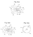
In an exemplary embodiment, the orthopaedic device 100 includes multiple attachments to bone via a plurality of attachment members 110 attached to rib bones 15 or transverse processes 16. The attachment members 110 can include a clamp 120-screw 114 combination (shown in FIGS. 3( a)-3(e)), or other suitable combination to secure the attachment members 110 to the transverse process 16 or rib bone 15.
The clamp 120 can, for example, fit at least around a portion of a rib bone 15 or transverse process 16. The clamp 120 can include an upper arm 126 with a shoulder portion 126 a, a lower arm 128 with a shoulder portion 128 a, and a hinge 124 about which the arms 126, 128 pivot. The hinge 124 can include an opening 124 a for the screw 114. As can be seen in FIG. 4( b), the screw 114 can be inserted through the opening 124 a. Each arm 126, 128 can include shoulder portions 126 a, 128 a adjacent to a screw head 115 when the screw 114 is inserted through the clamp 120 and into the rib bone 15 or transverse process 16. The clamp 120 can include a lever arm portion 121, which is best shown in FIGS. 3( a), 3(c) and 3(d). As the upper 126 arm and lower arm 128 rotate about the hinge 124 toward each other into a clamped position (FIG. 3( d)), the lever arm portion 121 rotates. For example, in FIG. 3( c), the lever arm portion 121 is in a different position in an open (unclamped position) then when the clamp is in a clamped position about a rib bone 15, such as shown in FIG. 3( d).
The clamp 120 can move into a clamped position (FIG. 3( d)) by action of the screw 114. As the screw 114 is advanced through the clamp 120 and, thus, hinge 124 and hinge opening 124 a, threads in the hinge opening 124(a) (not shown) correspond to and fit the screws on the screw 114. When the screw 114 is tightened into placement in the rib bone 15, the screw head 115 pushes against shoulders 126 a, 128 a of the upper arm 126 and lower arm 128. The pushing movement against the shoulders 126 a, 128 a is configured to rotate the upper arm 126 and lower arm 128 toward each other and into a clamped position. The shoulders 126 a, 128 a are offset from the hinge 124, the motion of the screw head 115 against the shoulders 126 a, 128 a forces the arms 126, 128 to clamp into a closed position.
Referring to FIGS. 4( a) and 4(b), the clamp 120-screw 114 combination can include a wedge portion 118. The wedge portion 118 is connected to or integral with the clamp 120 and is adjacent to the clamp hinge 124. When the screw 114 is tightened, the screw 114 abuts the wedge portion 118, which levers the clamp 120 to tighten around the rib bone 15. As the screw head 15 is tightened, the screw head 15 pushes against the clamp 120 and wedge portion 118 to tighten the clamp 120 against the rib bone 15, thus moving the upper arm 126 and lower arm 128 toward each other into a clamped position.
Each attachment member 110 also includes a connector or connector member 112, such as shown in FIGS. 4( a) and 4(b), for seating a spacer member 150, such as shown in FIGS. 7( b) and 7(c). The connector member 112 can be connected to or integral with the screw head 115. The connector member 112 geometry can vary depending upon the particular spacer member 150; preferably the connector member is in the shape of a plate. In FIGS. 4( a) and 4(b), the connector member 112 can include an opening 113 to engage with a corresponding spacer member 150. The spacer member 150 can have a suitable geometry, such as a projection, to mate with and attach (preferably releasably) with the opening 113.
Referring to FIG. 5( a), the clamp 120-screw 114 combination is shown in which the screw 114 includes a connector member 112 having protrusions 117 (or pegs) extending from opposite sides of the connector member 112. The protrusions 117 are provided to attach (preferably releasably) to a corresponding portion of a spacer member 150. For example, the protrusions 117 could extend into a corresponding hole in a spacer member 150.
Referring to FIG. 5( b), a clamp 120-screw 170 combination is shown attached to a rib bone 15 according to another embodiment. In this embodiment, the screw 170 includes a screw head 172 with a geometry configured to couple with and releasably engage with a corresponding spacer member 150. The screw head 172 can include a generally rectangular protrusion or extension 174 that protrudes out from a top surface 173 of the screw head 172. For example, the protrusion 174 could extend into a corresponding hole in a spacer member 150. In an exemplary embodiment, the attachment member 110, such as the clamp 120-screw 170 combination of FIG. 5( b), does not extend all the way around a rib bone 15. For example, the clamp 120 may attach only to opposite sides of the rib bone 15, but it need not encircle the rib bone 15. The clamp 120-screw 170 combination also is rotationally stable because the screw 170 prevents the clamp 120 from rotating around or sliding along the rib bone 15 despite the clamp 120 being non-circumferential. The screw 170 extends through a portion of the clamp 120 and tightens (screws) into the rib bone 15 or transverse process 16. The screw 170 can act as a barrier to rotational or sliding movement of the clamp 120 when screwed into the rib bone 15 or transverse process 16.
Referring to FIG. 5( c), a clamp 120-screw 180 combination is shown attached to a rib bone 15 according to another embodiment. In this embodiment, the screw 180 can include a screw head 182 with a rounded protrusion 184 extending from the screw head 182. The rounded protrusion 184 includes a hole or passage 185 for receiving an alignment member or rod 220 (see FIG. 6) or any other suitable connector component of a corresponding spacer member 150. As the rib bones 15 are realigned and move, the rod 220 is capable of sliding within the opening 220. The rod 220 may be rigid, flexible, or expandable and can span multiple spinal levels. The rod 220 may be coupled to (via another protrusion 184 and hole 185, or other suitable connection) to another attachment member 110 attached to a different rib bone 15 or transverse process 16.
Referring to FIG. 5( d), a clamp 120-screw 190 combination is shown attached to a rib bone 15 according to another embodiment. In this embodiment, the screw 190 can include a screw head 192 with a geometry configured to couple with and releasably engage with a corresponding spacer member 150. The screw head 192 can include a generally rounded protrusion or extension 194 that protrudes out from a top surface 193 of the screw head 192. The protrusion 194 can include a well 195 or opening that does not pass completely through the protrusion. The well 195 and protrusion 194 are configured to couple with a corresponding spacer member 150. For example, the well 195 could engage with a corresponding projection on the spacer member 150.
Referring to FIG. 5( e), a clamp 120-screw 175 combination is shown attached to a rib bone 15 according to another embodiment. In this embodiment, the screw 175 can include a screw head 176 with a geometry configured to couple with and releasably engage with a corresponding spacer member 150. The screw head 176 can include a threaded protrusion or peg 178 that protrudes out from a top surface 177 of the screw head 176. The protrusion 178 includes threads 179 that are configured to mate with corresponding threads on a spacer member 150.
Referring to FIG. 6 , a screw 114 and connector member 212 are shown. The connector member 212 includes an opening (passage or channel) 214 for an alignment member or rod 220 to slide through. As the rib bones 15 are realigned and move, the rod 220 is capable of sliding within the opening 220. The rod 220 may be rigid, flexible, or expandable and can span multiple spinal levels. The rod 220 may be coupled to (via another connector member 212, or other suitable connection) to another attachment member 110 attached to a different rib bone 15 or transverse process 16. For example, FIG. 6 illustrates the rod 220 extending through two adjacent screws 114 and corresponding connector members 212. The rod 220 is configured to connect all attachment members 110 and can be used to align attachment points on rib bones 15. For example, the openings 220 on the connector members 212 of all attachment members 110 must all be sufficiently aligned such that the rod 220 can slide through all of the openings 220. The rod 220 can also help improve spinal growth by helping direct movement of the rib bones 15 by aligning the rib bones 15. The rod 220 is preferably unthreaded and is slidably positioned within all of the openings 220.
According to an exemplary embodiment, spacer members 150 may be positioned between attachment members 110 and result in the lengthening of the assembled orthopaedic device 100. The spacer members 150 may allow motion (bending or twisting or flexing) between the attachment members 110. The motion may be constrained so as to only allow bending in a single direction by selection of appropriate materials for the spacer member 150. For example, the spacer member 150 can comprise a polymer as described below.
The spacer members 150 may be positioned posterior to or lateral to the attachment members 110. The spacer members 150 may also be anterior to the attachment members 110, such as when the device 100 is placed from an anterior approach to the rib heads 14 via the chest. Referring to FIG. 1( b), which illustrates the spine 10 from an anterior view, the attachment members 110 and spacer members 150 can be attached to the rib bones 15 from a frontal (anterior) approach that reverses the direction which the attachment members 110 and spacer members 150 face. In other words, if the screw head 115 faces towards a back-side of a patient with the orthopaedic device, the screw head 115 in the anterior position would face the front-side of the patent.
One possible type of spacer member 250 is a spring 252, such as shown in FIG. 8 . The spring 252 may be a nitinol spring that is implanted between the attachment members 110 in a compressed state and then simultaneously expanded with those at other spinal segments. The spring 252 may be fabricated of nitinol or another suitable metal that can be induced to change shape or expand. The spring 352 may comprise a shape memory alloy. The spring 252 may be a coil spring.
Referring to FIGS. 9( a) and 9(b), the spacer member 350 may be a polymer 352 in an alternative embodiment. The polymer 352 may be a hydrogel that can be induced to change shape or expand. For example, the polymer 352 may comprise a polyvinyl hydrogel. The spacer member 350 may be fabricated by certain polymeric hydrogels, which may be inserted in a dehydrated state and then expand as they absorb water from the surrounding muscle tissues that overlie the assembly after completion of the surgery. The polymer 352 may also include a housing 354. The housing 354 can be a fabric housing. The fabric housing 354 can comprise a wire mesh, such as shown in FIG. 9( b).
The spacer member 350, according to an exemplary embodiment, may have a composite with a reinforcing fiber pattern within the polymer matrix 352 to allow expansion in a preferential (e.g., longitudinal) direction.
Another type of spacer member 150 may be electromagnetic with a small motor (not shown). The electromagnetic motor may have a housing that expands in the presence of an applied magnetic field. The electromagnetic motor may incorporate a screw that elongates in the presence of an applied magnetic field which thus produces an elongation and distractive force between the attachment members 110.
In alternative embodiments, the spacer member 150 may include a threaded turnbuckle assembly, such as shown in FIGS. 10( a) and 10(b). The screw 114 includes a connector portion 412 with a passage or opening 414. The interior of the passage 414 is threaded to mate with threads on a threaded rod or member 420. The rod can extend between two or more attachment members 110 and is threadably attached to the connector portion 412. A nut 422 can be positioned on the threaded rod 420 adjacent to connector portion 412. The threaded rod 420 and connector portion 412 (turnbuckle assembly) can be adjusted to provide a distraction force by movement of the threaded rod 420 within the passages 414 of adjacent connector portions 412. The threaded rod 420 can be threaded into the passages 414 to have the connector portions 412 (and thus, attachment members 110 and attached rib bones 15) closer together, such as shown in FIG. 10( a). Unthreading the threaded rod 420 from the passages 414 can push the connector plates 412 apart to provide a distraction force on the associated rib bones 15.
Although the orthopaedic device 100 has been described as a fusionless device, according to another exemplary embodiment, the orthopaedic device 100 also may be used as a fusion device for internal fixation if combined with a bone-graft. For example, the device 100 can be used as a temporary splint or holding device to keep bones in a correct fused alignment/position until the bone graft is capable of fusing together the bones. When fusion of the bones is complete, the device 100 can be removed.
The FIGURES illustrate the clamp 120 attached to a rib bone 15, but it should be known that the clamp 120 could can also attach to a rib head 14, transverse process 16, lamina 19, or any other suitable location. According to an exemplary embodiment, the device 100 may be non-rigid and expandable.
The device 100 can also be made of a material that is biocompatible and/or include a biocompatible coating on the attachment members and/or spacer members to enhance fixation of the attachment members to bone comprised of a porous surface texture. The biocompatible coating/material can comprise, for example, hydroxyappetite.
It is important to note that the construction and arrangement of the orthopaedic device as shown in the various exemplary embodiments is illustrative only. Although only a few embodiments have been described in detail in this disclosure, those skilled in the art who review this disclosure will readily appreciate that many modifications are possible (e.g., variations in sizes, dimensions, structures, shapes and proportions of the various elements, values of parameters, mounting arrangements, use of materials, colors, orientations, etc.) without materially departing from the novel teachings and advantages of the subject matter disclosure herein. For example, elements shown as integrally formed may be constructed of multiple parts or elements, the position of elements may be reversed or otherwise varied, and the nature or number of discrete elements or positions may be altered or varied. Accordingly, all such modifications are intended to be included within the scope of the present disclosure. The order or sequence of any process or method steps may be varied or re-sequenced according to alternative embodiments. Other substitutions, modifications, changes and omissions may be made in the design, operating conditions and arrangement of the exemplary embodiments.
Claims (19)
1. An attachment member for an orthopaedic device for realigning bone segments, the attachment member comprising:
a clamp to attach to a rib bone, a lamina, or a transverse process of a vertebra, the clamp including an upper arm, a lower arm, and a hinge; and
a screw inserted into an opening in the clamp, the screw including a screw head and a longitudinal axis that extends along a length of the screw, the screw configured to, upon tightening, advance through the opening in the clamp, to fix into the rib bone, the lamina, or the transverse process to prevent rotational movement or sliding of the clamp along the rib bone, the lamina, or the transverse process,
wherein the upper arm includes a first shoulder having a first prominence and wherein the lower arm includes a second shoulder having a second prominence, the first prominence and the second prominence being positioned adjacent to the hinge such that as the screw is tightened to advance through the opening in the clamp to fix into the rib bone, the lamina, or the transverse process, the screw head pushes against the first prominence and the second prominence to force the upper and lower arms to pivot about the hinge to a clamped position,
wherein the clamp includes a first clamp and the attachment member further comprises:
a second clamp to attach to a second rib bone, a second lamina, or a second transverse process of a second vertebra, the second clamp including a second clamp upper arm, a second clamp lower arm, and a second clamp hinge, the second clamp upper arm and the second clamp lower arm including a third clamp shoulder and a fourth clamp should respectively, the third clamp shoulder and the further clamp shoulder including a third prominence and a fourth prominence respectively, the third prominence and the fourth prominence being positioned adjacent to the hinge;
a second screw inserted into a second clamp opening in the second clamp, the second screw including a second screw head, a second longitudinal axis that extends along a length of the seconds screw, the second screw configured to, upon tightening, advance through the second clamp opening in the second clamp, to fix into the second rib bone, the second lamina, or the second transverse process to prevent rotational movement or sliding of the second clamp along the second rib bone, the second lamina, or the second transverse process; and
a spacer member coupled to the first clamp and the second clamp.
2. The attachment member of claim 1 , wherein the spacer member is expandable.
3. The attachment member of claim 1 , wherein the spacer member is flexible.
4. The attachment member of claim 1 , wherein the spacer member comprises a polymer.
5. The attachment member of claim 4 , wherein the spacer member comprises a composite with a reinforcing tiber pattern within a polymer matrix.
6. The attachment member of claim 5 , wherein the spacer member elongates in one direction.
7. The attachment member of claim 6 , wherein the spacer member includes a fabric housing.
8. The attachment member of claim 7 , wherein the spacer member comprises a wire mesh.
9. The attachment member of claim 1 , wherein the spacer member comprises a spring.
10. The attachment member of claim 9 , wherein the spring comprises a shape memory alloy.
11. The attachment member of claim 1 , herein the first prominence and the second prominence include a wedge.
12. The attachment member of claim 1 , wherein the attachment members comprise a biocompatible material to enhance fixation of the attachment members to the rib bones or transverse processes.
13. The attachment member of claim 12 , wherein the biocompatible material comprises hydroxyapatite.
14. A method of attaching an orthopaedic device to at least one of a rib bone, a lamina, and a transverse process of a vertebra, the method comprising:
clamping a clamp including an upper arm, a lower arm, and a hinge to the rib bone, lamina, or transverse process, the upper arm and the lower arm including a shoulder having a prominence positioned adjacent to the hinge;
advancing a screw into an opening in the clamp, the screw including a screw head and a first longitudinal axis that extends along a length of the screw, such that as the screw is tightened to advance through the opening in the clamp the screw head pushes against the prominence to force the upper and lower arms to pivot toward one another into a clamped position; and
fixing the screw into the at least one of the rib bone, the lamina, and the transverse process as the screw is advanced into the opening in the clamp to prevent rotational movement or sliding of the clamp along the at least one of the rib bone, the lamina, and the transverse process.
15. The method of attaching an orthopaedic device of claim 14 , wherein the first clamp and the second clamp comprise a biocompatible material to enhance fixation of the first clamp and the second clamp to the rib bones or transverse processes.
16. The method of attaching an orthopaedic device of claim 15 , wherein the biocompatible material comprises hydroxyapatite.
17. The method of attaching an orthopaedic device of claim 14 , wherein the first clamp and the second clamp comprise a biocompatible coating to enhance fixation of the attachment members to the rib bones or transverse processes.
18. The method of attaching an orthopaedic device of claim 17 , wherein the biocompatible coating comprises hydroxyapatite.
19. The method of attaching an orthopaedic device of claim 14 , wherein the clamp includes a first clamp and wherein the method further comprises:
clamping a second clamp to one of a second rib bone, lamina, and transverse process, the second clamp including a second clamp upper arm, a second clamp lower arm, and a second clamp hinge, the second clamp upper arm and the second clamp lower including second clamp shoulder including second clamp prominence positioned adjacent to the second clamp hinge;
advancing a second screw into a second clamp opening in the second clamp, the second screw including a second screw head, a second longitudinal axis that extends along a length of the seconds screw, such that as the second screw is tightened to advance through the second clamp opening, the second screw head pushes against the second clamp prominence to force the second clamp upper and lower arms to pivot toward one another into a second clamped position;
fixing the second screw into one of the second rib bone, lamina, and transverse process as the second screw is advanced into the first opening in the clamp to prevent rotational movement or sliding of the second clamp along the second rib bone, lamina, and transverse process; and
coupling a spacer member to the first clamp and the second clamp.
Priority Applications (1)
| Application Number | Priority Date | Filing Date | Title |
|---|---|---|---|
| US14/444,860 US9204899B2 (en) | 2007-07-26 | 2014-07-28 | Segmental orthopedic device for spinal elongation and for treatment of scoliosis |
Applications Claiming Priority (3)
| Application Number | Priority Date | Filing Date | Title |
|---|---|---|---|
| US93509807P | 2007-07-26 | 2007-07-26 | |
| US12/149,403 US8790380B2 (en) | 2007-07-26 | 2008-04-30 | Segmental orthopaedic device for spinal elongation and for treatment of scoliosis |
| US14/444,860 US9204899B2 (en) | 2007-07-26 | 2014-07-28 | Segmental orthopedic device for spinal elongation and for treatment of scoliosis |
Related Parent Applications (1)
| Application Number | Title | Priority Date | Filing Date |
|---|---|---|---|
| US12/149,403 Continuation US8790380B2 (en) | 2007-07-26 | 2008-04-30 | Segmental orthopaedic device for spinal elongation and for treatment of scoliosis |
Publications (2)
| Publication Number | Publication Date |
|---|---|
| US20140336705A1 US20140336705A1 (en) | 2014-11-13 |
| US9204899B2 true US9204899B2 (en) | 2015-12-08 |
Family
ID=39523551
Family Applications (2)
| Application Number | Title | Priority Date | Filing Date |
|---|---|---|---|
| US12/149,403 Active 2030-09-10 US8790380B2 (en) | 2007-07-26 | 2008-04-30 | Segmental orthopaedic device for spinal elongation and for treatment of scoliosis |
| US14/444,860 Active US9204899B2 (en) | 2007-07-26 | 2014-07-28 | Segmental orthopedic device for spinal elongation and for treatment of scoliosis |
Family Applications Before (1)
| Application Number | Title | Priority Date | Filing Date |
|---|---|---|---|
| US12/149,403 Active 2030-09-10 US8790380B2 (en) | 2007-07-26 | 2008-04-30 | Segmental orthopaedic device for spinal elongation and for treatment of scoliosis |
Country Status (5)
| Country | Link |
|---|---|
| US (2) | US8790380B2 (en) |
| EP (1) | EP2182871B1 (en) |
| AU (1) | AU2008279798B2 (en) |
| CA (1) | CA2694437C (en) |
| WO (1) | WO2009014567A1 (en) |
Cited By (22)
| Publication number | Priority date | Publication date | Assignee | Title |
|---|---|---|---|---|
| US10206719B2 (en) | 2016-12-16 | 2019-02-19 | Nuvasive, Inc. | Bone hook apparatus |
| US10349982B2 (en) | 2011-11-01 | 2019-07-16 | Nuvasive Specialized Orthopedics, Inc. | Adjustable magnetic devices and methods of using same |
| US10478232B2 (en) | 2009-04-29 | 2019-11-19 | Nuvasive Specialized Orthopedics, Inc. | Interspinous process device and method |
| US10617453B2 (en) | 2015-10-16 | 2020-04-14 | Nuvasive Specialized Orthopedics, Inc. | Adjustable devices for treating arthritis of the knee |
| US10646262B2 (en) | 2011-02-14 | 2020-05-12 | Nuvasive Specialized Orthopedics, Inc. | System and method for altering rotational alignment of bone sections |
| US10660675B2 (en) | 2010-06-30 | 2020-05-26 | Nuvasive Specialized Orthopedics, Inc. | External adjustment device for distraction device |
| US10729470B2 (en) | 2008-11-10 | 2020-08-04 | Nuvasive Specialized Orthopedics, Inc. | External adjustment device for distraction device |
| US10743794B2 (en) | 2011-10-04 | 2020-08-18 | Nuvasive Specialized Orthopedics, Inc. | Devices and methods for non-invasive implant length sensing |
| US10751094B2 (en) | 2013-10-10 | 2020-08-25 | Nuvasive Specialized Orthopedics, Inc. | Adjustable spinal implant |
| US10835292B2 (en) | 2018-06-13 | 2020-11-17 | Nuvasive, Inc. | Rib fixation device and related methods |
| US10835290B2 (en) | 2015-12-10 | 2020-11-17 | Nuvasive Specialized Orthopedics, Inc. | External adjustment device for distraction device |
| US10918425B2 (en) | 2016-01-28 | 2021-02-16 | Nuvasive Specialized Orthopedics, Inc. | System and methods for bone transport |
| US11191579B2 (en) | 2012-10-29 | 2021-12-07 | Nuvasive Specialized Orthopedics, Inc. | Adjustable devices for treating arthritis of the knee |
| US11202707B2 (en) | 2008-03-25 | 2021-12-21 | Nuvasive Specialized Orthopedics, Inc. | Adjustable implant system |
| US11234849B2 (en) | 2006-10-20 | 2022-02-01 | Nuvasive Specialized Orthopedics, Inc. | Adjustable implant and method of use |
| US11246694B2 (en) | 2014-04-28 | 2022-02-15 | Nuvasive Specialized Orthopedics, Inc. | System for informational magnetic feedback in adjustable implants |
| US11357549B2 (en) | 2004-07-02 | 2022-06-14 | Nuvasive Specialized Orthopedics, Inc. | Expandable rod system to treat scoliosis and method of using the same |
| US11439449B2 (en) | 2014-12-26 | 2022-09-13 | Nuvasive Specialized Orthopedics, Inc. | Systems and methods for distraction |
| US11612416B2 (en) | 2015-02-19 | 2023-03-28 | Nuvasive Specialized Orthopedics, Inc. | Systems and methods for vertebral adjustment |
| US11723778B1 (en) | 2021-09-23 | 2023-08-15 | Nofusco Corporation | Vertebral implant system and methods of use |
| US11806247B2 (en) | 2020-06-15 | 2023-11-07 | Nofusco Corporation | Intravertebral implant system and methods of use |
| US11883300B2 (en) | 2020-06-15 | 2024-01-30 | Nofusco Corporation | Orthopedic implant system and methods of use |
Families Citing this family (41)
| Publication number | Priority date | Publication date | Assignee | Title |
|---|---|---|---|---|
| EP2182871B1 (en) * | 2007-07-26 | 2014-07-02 | Glenn R. Buttermann M. D. | Segmental orthopedic device for spinal elongation and for treatment of scoliosis |
| US9204908B2 (en) | 2007-07-26 | 2015-12-08 | Dynamic Spine, Llc | Segmental orthopedic device for spinal elongation and for treatment of scoliosis |
| US8057472B2 (en) | 2007-10-30 | 2011-11-15 | Ellipse Technologies, Inc. | Skeletal manipulation method |
| US8840647B2 (en) * | 2008-08-05 | 2014-09-23 | The Cleveland Clinic Foundation | Facet augmentation |
| US20100094302A1 (en) * | 2008-10-13 | 2010-04-15 | Scott Pool | Spinal distraction system |
| US11241257B2 (en) | 2008-10-13 | 2022-02-08 | Nuvasive Specialized Orthopedics, Inc. | Spinal distraction system |
| US8197490B2 (en) | 2009-02-23 | 2012-06-12 | Ellipse Technologies, Inc. | Non-invasive adjustable distraction system |
| EP2473116B1 (en) | 2009-09-04 | 2019-12-04 | NuVasive Specialized Orthopedics, Inc. | Bone growth device |
| AU2011264818B2 (en) | 2010-06-10 | 2015-06-18 | Globus Medical, Inc. | Low-profile, uniplanar bone screw |
| US8734488B2 (en) | 2010-08-09 | 2014-05-27 | Ellipse Technologies, Inc. | Maintenance feature in magnetic implant |
| EP2471476A1 (en) * | 2010-11-10 | 2012-07-04 | Zimmer Spine | Bone anchor |
| JP6044961B2 (en) * | 2011-06-20 | 2016-12-14 | 国立大学法人秋田大学 | Spine brake |
| US8961570B2 (en) * | 2012-01-24 | 2015-02-24 | Warsaw Othopedic, Inc. | Spinal correction system and method |
| US20130338714A1 (en) | 2012-06-15 | 2013-12-19 | Arvin Chang | Magnetic implants with improved anatomical compatibility |
| WO2014032118A1 (en) | 2012-08-31 | 2014-03-06 | Newsouth Innovations Pty Limited | Bone stabilization device and methods of use |
| US9044281B2 (en) | 2012-10-18 | 2015-06-02 | Ellipse Technologies, Inc. | Intramedullary implants for replacing lost bone |
| GB201220042D0 (en) * | 2012-11-07 | 2012-12-19 | Murray David W | Adjusting spinal curvature |
| US9731159B2 (en) | 2012-11-11 | 2017-08-15 | Timothy Reynolds | Exercise equipment adapter |
| US20140135186A1 (en) * | 2012-11-11 | 2014-05-15 | Timothy Reynolds | Exercise Equipment Adapter |
| US9320542B2 (en) * | 2012-11-12 | 2016-04-26 | Graeme A. Browne | Device for treating flail chest |
| US9179938B2 (en) | 2013-03-08 | 2015-11-10 | Ellipse Technologies, Inc. | Distraction devices and method of assembling the same |
| EP2967675B1 (en) * | 2013-03-11 | 2021-07-28 | Dynamic Spine, LLC | Screw-clamp orthopedic device and method of assembling |
| US10226242B2 (en) | 2013-07-31 | 2019-03-12 | Nuvasive Specialized Orthopedics, Inc. | Noninvasively adjustable suture anchors |
| US9801734B1 (en) | 2013-08-09 | 2017-10-31 | Nuvasive, Inc. | Lordotic expandable interbody implant |
| US9592083B2 (en) | 2013-08-30 | 2017-03-14 | New South Innovations Pty Limited | Spine stabilization device |
| WO2016044728A1 (en) * | 2014-09-18 | 2016-03-24 | Proception Medical, Llc | Fusion devices, systems and related methods |
| KR102559778B1 (en) | 2014-10-23 | 2023-07-26 | 누베이시브 스페셜라이즈드 오소페딕스, 인크. | Remotely adjustable interactive bone reshaping implant |
| CA2917676A1 (en) | 2015-01-13 | 2016-07-13 | Stryker European Holdings I, Llc | Growing rods and methods of use |
| US9451994B1 (en) | 2015-06-19 | 2016-09-27 | Amendia, Inc. | Spinal implant revision device |
| WO2017139548A1 (en) | 2016-02-10 | 2017-08-17 | Nuvasive Specialized Orthopedics, Inc. | Systems and methods for controlling multiple surgical variables |
| WO2018234977A1 (en) | 2017-06-20 | 2018-12-27 | A-Line Orthopaedics Corporation | Clamp implant for posterior arch of the atlas |
| WO2019074722A2 (en) * | 2017-10-10 | 2019-04-18 | Miki Roberto Augusto | Universal orthopedic clamp |
| US10813675B2 (en) * | 2017-11-30 | 2020-10-27 | DePuy Synthes Products, Inc. | Bone fracture fixation clamp with bone remodeling adaptability |
| US11446064B2 (en) | 2018-04-26 | 2022-09-20 | Stryker European Operations Holdings Llc | Orthopedic growing devices |
| EP3922039A1 (en) | 2019-02-07 | 2021-12-15 | NuVasive Specialized Orthopedics, Inc. | Ultrasonic communication in medical devices |
| US11589901B2 (en) | 2019-02-08 | 2023-02-28 | Nuvasive Specialized Orthopedics, Inc. | External adjustment device |
| EP3962380A4 (en) * | 2019-05-01 | 2023-06-07 | Grant D. Hogue | Internal elastic brace for treating scoliosis |
| US20220265327A1 (en) | 2021-02-23 | 2022-08-25 | Nuvasive Specialized Orthopedics, Inc. | Adjustable implant, system and methods |
| US11737787B1 (en) | 2021-05-27 | 2023-08-29 | Nuvasive, Inc. | Bone elongating devices and methods of use |
| US20230032049A1 (en) * | 2021-07-29 | 2023-02-02 | David Skaggs | Systems and methods for treatment of spinal deformities |
| WO2023155033A1 (en) * | 2022-02-15 | 2023-08-24 | Mazor Robotics Ltd. | Reusable registration kit for spinal robotics |
Citations (222)
| Publication number | Priority date | Publication date | Assignee | Title |
|---|---|---|---|---|
| US945213A (en) * | 1909-01-09 | 1910-01-04 | Jasper Blackburn | Insulator-clamp. |
| US1766546A (en) | 1928-11-13 | 1930-06-24 | Axel H Roos | Combination calipers |
| US2537322A (en) | 1947-03-13 | 1951-01-09 | W C Dillon & Company Inc | Tensile grip |
| US2543550A (en) | 1948-11-16 | 1951-02-27 | Verne L Kneeland | Fastener setting machine |
| US2589520A (en) | 1947-05-27 | 1952-03-18 | Wallenius Tuomo Jaakk Hermanni | Fixture for cameras or other similar apparatus |
| US2722440A (en) | 1950-03-17 | 1955-11-01 | Barton Percy Charles | Couplings or fastenings for scaffolding and like poles |
| US2824913A (en) | 1954-01-05 | 1958-02-25 | Ashton B Taylor | Hanger for electrical trolley |
| US4085744A (en) * | 1977-01-31 | 1978-04-25 | David Warren Lewis | Spinal column prostheses orthoses |
| DE2821678A1 (en) | 1978-05-12 | 1979-11-22 | Sulzer Ag | IMPLANT THAT CAN BE INSERTED BETWEEN NEIGHBORING Vertebrae |
| US4361141A (en) * | 1979-07-27 | 1982-11-30 | Zimmer Usa, Inc. | Scoliosis transverse traction assembly |
| US4364381A (en) | 1980-01-31 | 1982-12-21 | Sher Jay H | Surgical clamp and drill-guiding instrument |
| US4409968A (en) * | 1980-02-04 | 1983-10-18 | Drummond Denis S | Method and apparatus for engaging a hook assembly to a spinal column |
| US4411259A (en) * | 1980-02-04 | 1983-10-25 | Drummond Denis S | Apparatus for engaging a hook assembly to a spinal column |
| US4422451A (en) * | 1982-03-22 | 1983-12-27 | Ali Kalamchi | Spinal compression and distraction instrumentation |
| US4531522A (en) | 1983-06-20 | 1985-07-30 | Ethicon, Inc. | Two-piece tissue fastener with locking top and method for applying same |
| US4611582A (en) * | 1983-12-27 | 1986-09-16 | Wisconsin Alumni Research Foundation | Vertebral clamp |
| US4619447A (en) | 1985-10-03 | 1986-10-28 | Blake John B | Clamping device |
| US4702447A (en) * | 1984-11-29 | 1987-10-27 | Westwood Iii Samuel M | Clamp device |
| US4823636A (en) | 1987-04-28 | 1989-04-25 | Suska Charles R | Wrenchable C-clamp |
| US4852841A (en) | 1988-10-12 | 1989-08-01 | Sebring John P | Device for clamping the edge of a table |
| US4901964A (en) | 1985-01-22 | 1990-02-20 | Mcconnell Bernard E | Rail clamp |
| US4950270A (en) | 1989-02-03 | 1990-08-21 | Boehringer Mannheim Corporation | Cannulated self-tapping bone screw |
| WO1990012553A1 (en) | 1989-04-14 | 1990-11-01 | Campbell Robert M Jr | Expandable vertical prosthetic rib |
| US5007909A (en) * | 1986-11-05 | 1991-04-16 | Chaim Rogozinski | Apparatus for internally fixing the spine |
| US5030235A (en) | 1990-04-20 | 1991-07-09 | Campbell Robert M Jr | Prosthetic first rib |
| US5074864A (en) * | 1988-12-21 | 1991-12-24 | Zimmer, Inc. | Clamp assembly for use in a spinal system |
| US5096150A (en) * | 1984-11-29 | 1992-03-17 | Westwood Samuel M | Clamp device |
| US5112332A (en) * | 1988-12-21 | 1992-05-12 | Zimmer, Inc. | Method of performing spinal surgery |
| US5116334A (en) * | 1988-12-21 | 1992-05-26 | Zimmer, Inc. | Posterior spinal system and method |
| US5147359A (en) * | 1988-12-21 | 1992-09-15 | Zimmer, Inc. | Spinal hook body |
| US5190543A (en) | 1990-11-26 | 1993-03-02 | Synthes (U.S.A.) | Anchoring device |
| US5290289A (en) | 1990-05-22 | 1994-03-01 | Sanders Albert E | Nitinol spinal instrumentation and method for surgically treating scoliosis |
| US5330472A (en) * | 1990-06-13 | 1994-07-19 | Howmedica Gmbh | Device for applying a tensional force between vertebrae of the human vertebral column |
| US5334203A (en) * | 1992-09-30 | 1994-08-02 | Amei Technologies Inc. | Spinal fixation system and methods |
| US5344422A (en) | 1989-10-30 | 1994-09-06 | Synthes (U.S.A.) | Pedicular screw clamp |
| US5352225A (en) * | 1993-01-14 | 1994-10-04 | Yuan Hansen A | Dual-tier spinal clamp locking and retrieving system |
| US5380326A (en) * | 1993-11-12 | 1995-01-10 | Lin; Chih-I | Clamping device for vertebral locking rod |
| US5413576A (en) | 1993-02-10 | 1995-05-09 | Rivard; Charles-Hilaire | Apparatus for treating spinal disorder |
| US5415659A (en) * | 1993-12-01 | 1995-05-16 | Amei Technologies Inc. | Spinal fixation system and pedicle clamp |
| US5423857A (en) * | 1993-11-02 | 1995-06-13 | Ethicon, Inc. | Three piece surgical staple |
| US5507747A (en) * | 1994-03-09 | 1996-04-16 | Yuan; Hansen A. | Vertebral fixation device |
| US5520689A (en) | 1992-06-04 | 1996-05-28 | Synthes (U.S.A.) | Osteosynthetic fastening device |
| US5586983A (en) * | 1990-05-22 | 1996-12-24 | Sanders; Albert E. | Bone clamp of shape memory material |
| US5630816A (en) * | 1995-05-01 | 1997-05-20 | Kambin; Parviz | Double barrel spinal fixation system and method |
| US5632744A (en) * | 1992-06-08 | 1997-05-27 | Campbell, Jr.; Robert M. | Segmental rib carriage instrumentation and associated methods |
| WO1997029707A1 (en) | 1996-02-15 | 1997-08-21 | Plus Endoprothetik Ag | Osteosynthetic mounting element |
| US5662648A (en) | 1993-03-15 | 1997-09-02 | Orthofix S.R.L. | Method and apparatus for the external setting of fractures |
| US5676665A (en) | 1995-06-23 | 1997-10-14 | Bryan; Donald W. | Spinal fixation apparatus and method |
| US5688273A (en) * | 1995-10-23 | 1997-11-18 | Fastenetix, Llc. | Spinal implant apparatus having a single central rod and plow hooks |
| US5688274A (en) * | 1995-10-23 | 1997-11-18 | Fastenetix Llc. | Spinal implant device having a single central rod and claw hooks |
| US5689864A (en) | 1997-03-03 | 1997-11-25 | The United States Of America As Represented By The Secretary Of The Navy | Rib clamp |
| US5697650A (en) | 1995-04-20 | 1997-12-16 | Spraying Systems Co. | Corrosion-free clip eyelet for spray nozzles |
| US5733284A (en) * | 1993-08-27 | 1998-03-31 | Paulette Fairant | Device for anchoring spinal instrumentation on a vertebra |
| US5800548A (en) * | 1996-03-05 | 1998-09-01 | Bruno Franck | Device for transverse spinal connection |
| US6053917A (en) | 1996-09-24 | 2000-04-25 | Sdgi Holdings, Inc. | Multi-axial bone screw assembly |
| US6136000A (en) | 1996-01-19 | 2000-10-24 | Louis; Rene | Anchoring device for posterior vertebral osteosynthesis |
| FR2782911B1 (en) | 1998-09-07 | 2000-11-24 | Euros Sa | SPINAL IMPLANT WITH MEANS FOR ATTACHING A VERTEBRUS AND A DEVICE FOR THE CROSS-LINKAGE OF TWO LONGITUDINAL RODS |
| US20020013585A1 (en) | 2000-06-30 | 2002-01-31 | Jose Gournay | Spinal implant for an osteosynthesis device |
| US20020019633A1 (en) * | 2000-08-07 | 2002-02-14 | Ray R. Charles | Tool for reducing spinal deformity |
| US6352537B1 (en) | 1998-09-17 | 2002-03-05 | Electro-Biology, Inc. | Method and apparatus for spinal fixation |
| US6375656B1 (en) | 1997-10-13 | 2002-04-23 | Dimso (Distribution Medicale Du Sud-Ouest) | Device for fixing a rod to a thin bone wall |
| US6387097B1 (en) | 1997-05-16 | 2002-05-14 | Scient'x Societe A Responsabilite Limitee | Implant for osteosynthesis device with hook |
| US20020095156A1 (en) | 2001-01-16 | 2002-07-18 | Axiomed, Inc. | Apparatus for attaching a cranial flap |
| US20020169451A1 (en) | 2001-05-02 | 2002-11-14 | Chung-Chun Yeh | System for fixing and recuperating vertebrae under treatment |
| US20030004511A1 (en) * | 2001-06-27 | 2003-01-02 | Ferree Bret A. | Polyaxial pedicle screw system |
| US20030032959A1 (en) | 1999-12-10 | 2003-02-13 | Chung-Chun Yeh | Spinal fixation hook and spinal fixation retrieval device |
| US20030045876A1 (en) * | 2001-09-05 | 2003-03-06 | Stahurski Consulting Inc. | Apparatus for retaining vertebrae in a desired spatial relationship |
| US6547789B1 (en) * | 1999-07-02 | 2003-04-15 | Sulzer Orthopedics Ltd. | Holding apparatus for the spinal column |
| US20030083659A1 (en) | 1997-05-15 | 2003-05-01 | Howmedica Osteonics Corp. | Transverse rod connector clip |
| US20030080267A1 (en) | 2001-10-29 | 2003-05-01 | Panavision, Inc. | Multi-sized clamp |
| US20030088251A1 (en) | 2001-11-05 | 2003-05-08 | Braun John T | Devices and methods for the correction and treatment of spinal deformities |
| US20030109882A1 (en) | 2001-08-01 | 2003-06-12 | Showa Ika Kohgyo Co., Ltd | Implant for bone connector |
| US20030109881A1 (en) * | 2001-08-01 | 2003-06-12 | Showa Ika Kohgyo Co., Ltd. | Implant for bone connector |
| US20030125738A1 (en) | 2002-01-03 | 2003-07-03 | Khanna Rohit Kumar | Laminoplasty with laminar stabilization method and system |
| US6589243B1 (en) | 1998-09-18 | 2003-07-08 | Guy Viart | Posterior backbone osteosynthesis device |
| US20030130659A1 (en) * | 2002-01-10 | 2003-07-10 | Haider Thomas T. | Orthopedic hook system |
| US6626909B2 (en) | 2002-02-27 | 2003-09-30 | Kingsley Richard Chin | Apparatus and method for spine fixation |
| US20030187437A1 (en) * | 2002-03-29 | 2003-10-02 | Depuy Acromed, Inc. | Serrated spinal hook |
| US20040030388A1 (en) | 2002-05-30 | 2004-02-12 | Null William B. | Laminoplasty devices and methods |
| WO2004019757A2 (en) | 2002-08-29 | 2004-03-11 | Loubert Suddaby | Spinal facet fixation device |
| US20040055429A1 (en) | 2002-09-23 | 2004-03-25 | Winkler John Andrew | Locking pliers tool with automatic jaw gap adjustment and adjustable clamping force capability |
| US20040064140A1 (en) | 2000-11-07 | 2004-04-01 | Jean Taylor | Vertebral arthrodesis equipment |
| US6719795B1 (en) | 2001-04-25 | 2004-04-13 | Macropore Biosurgery, Inc. | Resorbable posterior spinal fusion system |
| US20040111091A1 (en) | 2002-05-21 | 2004-06-10 | James Ogilvie | Reduction cable and bone anchor |
| US20040186472A1 (en) * | 2003-03-17 | 2004-09-23 | Edward L. Lewis | Connector for attaching an alignment rod to a bone structure |
| WO2005044152A1 (en) | 2003-11-07 | 2005-05-19 | Impliant Ltd. | Spinal prostheses |
| US20050131412A1 (en) * | 2003-10-20 | 2005-06-16 | Boris Olevsky | Bone plate and method for using bone plate |
| US20050171539A1 (en) | 2004-01-30 | 2005-08-04 | Braun John T. | Orthopedic distraction implants and techniques |
| US6926242B2 (en) * | 2003-08-22 | 2005-08-09 | Cateye Co., Ltd. | Fixing apparatus |
| US20050228377A1 (en) | 2004-04-07 | 2005-10-13 | Depuy Spine, Inc. | Spinal cross-connectors |
| US20050267475A1 (en) | 2004-05-27 | 2005-12-01 | Miller Archibald S Iii | Surgical device for capturing, positioning and aligning portions of a severed human sternum |
| US20050273100A1 (en) | 2004-06-04 | 2005-12-08 | Taylor Brett A | Variable laminoplasty implant |
| US20060036241A1 (en) | 2004-08-11 | 2006-02-16 | Tzony Siegal | Spinal surgery system and method |
| US20060058790A1 (en) | 2004-08-03 | 2006-03-16 | Carl Allen L | Spinous process reinforcement device and method |
| US7029472B1 (en) | 1999-06-01 | 2006-04-18 | Fortin Frederic | Distraction device for the bones of children |
| US20060084990A1 (en) | 2004-05-26 | 2006-04-20 | Jose Gournay | Dual anchor spinal implant apparatus |
| US20060116687A1 (en) | 2004-11-30 | 2006-06-01 | Miller Keith E | Side-loading adjustable bone anchor |
| US20060155279A1 (en) | 2004-10-28 | 2006-07-13 | Axial Biotech, Inc. | Apparatus and method for concave scoliosis expansion |
| US20060229616A1 (en) | 2005-03-03 | 2006-10-12 | Accin Corporation | Spinal stabilization using bone anchor seat and cross coupling with improved locking feature |
| US20060229615A1 (en) | 2005-02-18 | 2006-10-12 | Abdou M S | Devices and methods for dynamic fixation of skeletal structure |
| US20060235391A1 (en) * | 2005-03-08 | 2006-10-19 | Sutterlin Chester Iii | Facet joint stabilization |
| US20060241601A1 (en) | 2005-04-08 | 2006-10-26 | Trautwein Frank T | Interspinous vertebral and lumbosacral stabilization devices and methods of use |
| US20060247626A1 (en) | 2005-04-29 | 2006-11-02 | Sdgi Holdings, Inc. | Device for interconnecting components in spinal instrumentation |
| US7137986B2 (en) | 1999-12-17 | 2006-11-21 | Synthes (U.S.A.) | Transconnector for coupling spinal rods |
| US20060271193A1 (en) | 2003-09-26 | 2006-11-30 | Stephan Hartmann | Device for connecting a longitudinal member to a bone |
| US20060293663A1 (en) | 2005-04-21 | 2006-12-28 | Spine Wave, Inc. | Dynamic stabilization system for the spine |
| US20070016189A1 (en) * | 2005-06-30 | 2007-01-18 | Depuy Spine Sarl | Orthopedic clamping hook assembly |
| US20070072459A1 (en) * | 2005-09-23 | 2007-03-29 | Stahurski Consulting Inc. | Apparatus for retaining vertebrae |
| US20070083201A1 (en) | 2005-09-23 | 2007-04-12 | Jones Robert J | Apparatus and methods for spinal implant with variable link mechanism |
| US20070118118A1 (en) | 2005-10-21 | 2007-05-24 | Depuy Spine, Inc. | Adjustable bone screw assembly |
| US20070123883A1 (en) * | 2003-08-28 | 2007-05-31 | Ellis Thomas J | Bone fixation system |
| US7249399B2 (en) | 2004-08-05 | 2007-07-31 | Terry Taylor | Cargo securing systems for cargo bed |
| US20070225713A1 (en) * | 2004-10-20 | 2007-09-27 | Moti Altarac | Systems and methods for posterior dynamic stabilization of the spine |
| US20070239161A1 (en) * | 2006-04-06 | 2007-10-11 | Lukas Giger | Remotely Adjustable Tissue Displacement Device |
| US20070276384A1 (en) * | 2003-11-19 | 2007-11-29 | Frank Spratt | Hook for Fixing a Spinal Support Rod to a Vertebra |
| US20080033436A1 (en) | 2004-08-30 | 2008-02-07 | Vermillion Technologies, Llc | Device and method for treatment of spinal deformity |
| US20080077144A1 (en) | 2006-09-13 | 2008-03-27 | Crofford Theodore W | Self-opening skin staple |
| US20080103512A1 (en) * | 2006-10-23 | 2008-05-01 | G&L Consulting, Llc | Clamping system and method for fusing vertebral elements in a spine |
| US20080114401A1 (en) | 2006-11-10 | 2008-05-15 | Warsaw Orthopedic, Inc. | Posterior Fixation Devices and Methods of Use |
| US20080177315A1 (en) | 2006-12-20 | 2008-07-24 | Aesculap Ii, Inc. | Rod to Rod Connector |
| US20080228225A1 (en) | 2006-11-30 | 2008-09-18 | Paradigm Spine, Llc | Interlaminar-Interspinous Vertebral Stabilization System |
| US20080234766A1 (en) * | 2007-01-29 | 2008-09-25 | Polaris Biotechnology, Inc. | Craniospinal fusion method and apparatus |
| US20080234733A1 (en) * | 2007-03-19 | 2008-09-25 | Kelly Scrantz | Vertebral stabilization devices and associated surgical methods |
| FR2892617B1 (en) | 2005-11-02 | 2008-09-26 | Frederic Fortin | DAMPING DISPLACEMENT DEVICE AND CORRECTION ADJUSTABLE TO THE GROWTH OF THE RACHIS |
| US20080294200A1 (en) | 2007-05-25 | 2008-11-27 | Andrew Kohm | Spinous process implants and methods of using the same |
| US20080306551A1 (en) | 2004-03-25 | 2008-12-11 | Depuy International Ltd | Surgical Fastening |
| US20090018584A1 (en) * | 2007-01-29 | 2009-01-15 | Polaris Biotechnology, Inc. | Vertebra attachment method and system |
| US20090030462A1 (en) | 2007-07-26 | 2009-01-29 | Glenn R. Buttermann, M.D. | Segmental Orthopaedic device for spinal elongation and for treatment of Scoliosis |
| US20090030457A1 (en) | 2003-02-05 | 2009-01-29 | Janowski Brian P | Spinal Fixation Systems |
| US20090062869A1 (en) | 2007-08-28 | 2009-03-05 | Perception Raisonnement Action En Medecine | Minimally invasive bone fixation clamp for navigated surgeries |
| US20090105766A1 (en) | 2007-01-19 | 2009-04-23 | Matthew Thompson | Systems, Devices and Methods for the Correction of Spinal Deformities |
| US20090112263A1 (en) * | 2007-10-30 | 2009-04-30 | Scott Pool | Skeletal manipulation system |
| US20090118775A1 (en) | 2007-11-01 | 2009-05-07 | Burke Shawn M | Sternal Clamp |
| US20090118774A1 (en) | 2005-02-09 | 2009-05-07 | Mavrek Medical, Llc. | Sternal Closure Device with Ratchet Closure Mechanism |
| US20090163920A1 (en) * | 2007-07-03 | 2009-06-25 | Stephen Hochschuler | Facet fusion implant |
| US20090177230A1 (en) * | 2008-01-08 | 2009-07-09 | Polaris Biotechnology, Inc. | Osteointegration apparatus |
| US20090198277A1 (en) | 2007-12-28 | 2009-08-06 | Osteomed Spine, Inc. | Bone tissue fixation device and method |
| US20090248090A1 (en) | 2007-12-28 | 2009-10-01 | Pronto Products, Llc | Rib bone tissue clamp |
| US20090270929A1 (en) * | 2008-04-24 | 2009-10-29 | Loubert Suddaby | Facet joint fixation device |
| US7614173B2 (en) | 2005-08-02 | 2009-11-10 | Ki Ryong Kim | Road traffic-control signboard assembly having automatic return function |
| US20090287253A1 (en) * | 2008-05-15 | 2009-11-19 | Innovasis, Inc. | Polyaxial screw system |
| US7666210B2 (en) * | 2002-02-11 | 2010-02-23 | Scient'x Sa | Connection system between a spinal rod and a transverse bar |
| US20100057127A1 (en) | 2008-08-26 | 2010-03-04 | Mcguire Brian | Expandable Laminoplasty Fixation System |
| US20100069960A1 (en) * | 2008-09-17 | 2010-03-18 | Chaput Christopher D | Spinous Process Based Laminoplasty |
| US20100094303A1 (en) * | 2008-10-13 | 2010-04-15 | Arvin Chang | Spinal distraction system |
| US7703358B2 (en) * | 2005-04-11 | 2010-04-27 | Sistemas Technicos De Encofrados, S.A. | Adjustable clamp for securing shuttering panels |
| US20100121381A1 (en) * | 2008-06-09 | 2010-05-13 | Springback, Inc. | Surgical method and apparatus for treating spinal stenosis and stabilization of vertebrae |
| US7717938B2 (en) | 2004-08-27 | 2010-05-18 | Depuy Spine, Inc. | Dual rod cross connectors and inserter tools |
| US20100137913A1 (en) * | 2008-11-03 | 2010-06-03 | Roberto Khatchadourian | Adjustable rod assembly |
| US20100152575A1 (en) * | 2008-01-08 | 2010-06-17 | Polaris Biotechnology, Inc. | Mathematical Relationship of Strain, Neurological Dysfunction and Abnormal Behavior Resulting from Neurological Dysfunction of the Brainstem |
| US20100160979A1 (en) * | 2008-12-19 | 2010-06-24 | Clariance | Hinge mounting system for a spinal osteosynthesis device |
| US20100179597A1 (en) * | 2007-01-29 | 2010-07-15 | Polaris Biotechnology, Inc. | Craniospinal fusion method and apparatus |
| US20100198274A1 (en) | 2002-02-13 | 2010-08-05 | Jeffrey Eric Yeung | Intervertebral disc inserting device |
| US20100217271A1 (en) * | 2009-02-23 | 2010-08-26 | Ellipse Technologies, Inc. | Spinal distraction system |
| US20100222822A1 (en) * | 2002-08-28 | 2010-09-02 | Warsaw Orthopedic, Inc. | Posterior Fixation System |
| US20100241230A1 (en) | 2009-03-18 | 2010-09-23 | Depuy Spine, Inc. | Laminoplasty methods and devices |
| US20100249842A1 (en) | 2009-03-31 | 2010-09-30 | Dr. Hamid R. Mir | Spinous process cross-link |
| US20100274291A1 (en) * | 2009-04-23 | 2010-10-28 | Custom Spine, Inc. | Spinal Fixation Mechanism |
| US20100292739A1 (en) | 2009-05-15 | 2010-11-18 | Warsaw Orthopedic, Inc. | Bone Screws With Improved Locking Mechanisms |
| US20100305616A1 (en) * | 2008-01-14 | 2010-12-02 | John Carbone | Spinal fixation device and method |
| US7883532B2 (en) * | 2005-04-25 | 2011-02-08 | Spineco, Inc. | Vertebral pars interarticularis clamp a new spine fixation device, instrumentation, and methodology |
| US7901436B2 (en) | 2003-09-04 | 2011-03-08 | Zimmer Spine S.A.S. | Spinal implant |
| US7922746B2 (en) | 2006-08-31 | 2011-04-12 | Warsaw Orthopedic, Inc. | Spinal rod extenders and methods of use |
| US7927355B2 (en) | 2003-10-22 | 2011-04-19 | Pioneer Surgical Technology, Inc. | Crosslink for securing spinal rods |
| US7927357B2 (en) * | 2005-02-02 | 2011-04-19 | Depuy Spine, Inc. | Adjustable length implant |
| US20110106163A1 (en) | 2006-01-23 | 2011-05-05 | Hochschuler Stephen H | Interlaminar Stabilizing System |
| US20110111929A1 (en) | 2008-07-02 | 2011-05-12 | Allison Michael R | Combination kettle bell and dumbbell |
| US7942908B2 (en) * | 2005-02-02 | 2011-05-17 | Depuy Spine, Inc. | Adjustable length implant |
| US20110137353A1 (en) * | 2007-07-26 | 2011-06-09 | Buttermann Glenn R | Segmental orthopedic device for spinal elongation and for treatment of scoliosis |
| US20110144694A1 (en) * | 2009-12-11 | 2011-06-16 | Bruno Laeng | Bone fixation assembly |
| US7966703B2 (en) | 2005-04-11 | 2011-06-28 | Sistemas Tecnicos De Encofrados, S.A. | Clamp for securing shuttering panels |
| US20110160779A1 (en) | 2008-09-05 | 2011-06-30 | Synthes Usa, Llc | Bone fixation assembly |
| US7980521B2 (en) | 2007-05-04 | 2011-07-19 | Tyco Healthcare Group Lp | Medical device safety support with infinite positioning |
| US20110178552A1 (en) * | 2005-04-25 | 2011-07-21 | Spineco, Inc. | Vertebral pars interarticularis clamp a new spine fixation device, instrumentation, and methodology |
| US20110184463A1 (en) | 2008-08-07 | 2011-07-28 | The Children's Mercy Hospital | Sliding rod system for correcting spinal deformities |
| US8025683B2 (en) | 2006-04-28 | 2011-09-27 | Warsaw Orthopedic, Inc. | Open axle surgical implant |
| US8025678B2 (en) | 2008-03-26 | 2011-09-27 | Depuy Spine, Inc. | Interspinous process spacer having tight access offset hooks |
| US20110251643A1 (en) * | 2008-10-23 | 2011-10-13 | Lotfi Miladi | Spinal Osteosynthesis System |
| US20110257690A1 (en) | 2010-04-20 | 2011-10-20 | Warsaw Orthopedic, Inc. | Transverse and Sagittal Adjusting Screw |
| US8043337B2 (en) | 2006-06-14 | 2011-10-25 | Spartek Medical, Inc. | Implant system and method to treat degenerative disorders of the spine |
| US8048166B2 (en) | 2004-05-04 | 2011-11-01 | Biomet Manufacturing Corp. | Method and apparatus for constructing a modular acetabulum |
| US8051515B1 (en) | 2008-08-12 | 2011-11-08 | Bob Kring | Surgical bed clamp apparatus |
| US20110288592A1 (en) | 2010-03-30 | 2011-11-24 | Aeolin Llc | Side Opening Bone Fastener System |
| WO2011156573A1 (en) | 2010-06-10 | 2011-12-15 | Buttermann Glenn R | Low-profile, uniplanar bone screw |
| US8080037B2 (en) | 2008-01-04 | 2011-12-20 | Life Spine, Inc. | Spinal cross-connector with spinal extensor muscle curvature |
| US20110313323A1 (en) * | 2007-01-29 | 2011-12-22 | Polaris Biotechnology, Inc. | Method for treating a neurological disorder |
| US20120016420A1 (en) * | 2010-07-14 | 2012-01-19 | Naraghi Fred F | Devices, systems, and methods for inter-transverse process dynamic stabilization |
| US20120035656A1 (en) * | 2010-08-09 | 2012-02-09 | Ellipse Technologies, Inc. | External maintenance feature for magnetic implant |
| US20120035661A1 (en) * | 2010-08-09 | 2012-02-09 | Ellipse Technologies, Inc. | Maintenance feature in magnetic implant |
| US20120047690A1 (en) | 2008-02-27 | 2012-03-01 | Ginocchio Mark H | Self-aligning handling or storing device having side or top actuation and methods of use therefor |
| US20120088380A1 (en) | 2010-10-07 | 2012-04-12 | Smith Lawrence J | Electric ground clamp with pivoted jaws and single attached adjusting bolt and terminal block |
| US8172887B2 (en) | 2005-01-25 | 2012-05-08 | Lorenz Gabele | Lock and release mechanism for a sternal clamp |
| US8197543B2 (en) | 2004-11-20 | 2012-06-12 | Dajue Wang | Spinal prostheses |
| US8197515B2 (en) | 2008-02-18 | 2012-06-12 | Expanding Orthopedics Inc. | Cross-connector assembly |
| US8231655B2 (en) | 2003-07-08 | 2012-07-31 | Gmedelaware 2 Llc | Prostheses and methods for replacement of natural facet joints with artificial facet joint surfaces |
| US8241334B2 (en) | 2007-07-13 | 2012-08-14 | Life Spine, Inc. | Spinal cross-connector |
| US20120209328A1 (en) * | 2006-10-19 | 2012-08-16 | Simpirica Spine, Inc. | Structures and methods for constraining spinal processes with single connector |
| US8292924B2 (en) | 2007-10-05 | 2012-10-23 | Spineworks, Llc | Enhanced pedicle rod clamp device |
| US20120271352A1 (en) | 2011-03-28 | 2012-10-25 | Aesculap Ag | Facet joint implant |
| US20120271354A1 (en) | 2010-01-06 | 2012-10-25 | Implanet, Societe Anonyme | Vertebral attachment device |
| US8298275B2 (en) | 2009-10-30 | 2012-10-30 | Warsaw Orthopedic, Inc. | Direct control spinal implant |
| US20120283780A1 (en) | 2004-03-31 | 2012-11-08 | Depuy Spine, Inc. | Rod attachment for head to head cross connector |
| US8313514B2 (en) | 2006-05-15 | 2012-11-20 | Warsaw Orthopedic, Inc. | Device for interconnection of components in a spinal implant assembly |
| US20130041410A1 (en) * | 2011-08-08 | 2013-02-14 | Zimmer Spine, Inc. | Bone anchoring device |
| US20130046352A1 (en) * | 2011-08-15 | 2013-02-21 | K2M, Inc. | Laminar hook insertion device |
| US8430917B2 (en) | 2009-10-30 | 2013-04-30 | Warsaw Orthopedic, Inc. | Bone engaging implant with adjustment saddle |
| US20130131738A1 (en) * | 2011-05-10 | 2013-05-23 | Sean Powell | Bone fracture fixation clamp |
| US20130218208A1 (en) * | 2012-02-16 | 2013-08-22 | The Uab Research Foundation | Rod-receiving spinal fusion attachment elements |
| US20130231704A1 (en) * | 2010-11-10 | 2013-09-05 | Zimmer Spine | Bone anchor |
| US20130274807A1 (en) * | 2012-04-16 | 2013-10-17 | Aesculap Implant Systems, Llc | Rod to rod cross connector |
| US20130304129A1 (en) * | 2012-05-04 | 2013-11-14 | Alphatec Spine, Inc. | Surgical hook including flow path |
| US20140135853A1 (en) * | 2012-06-08 | 2014-05-15 | Medxpert Gmbh | Multi-Directional Thorax Wall Stabilisation |
| US20140214087A1 (en) * | 2013-01-29 | 2014-07-31 | Solana Surgical, Llc | Joint aligner implant |
| US20140222074A1 (en) * | 2013-02-01 | 2014-08-07 | DePuy Synthes Products, LLC | Bone support apparatus |
| US20140236234A1 (en) * | 2011-06-03 | 2014-08-21 | Kspine, Inc. | Spinal correction system actuators |
| US20140257488A1 (en) * | 2013-03-11 | 2014-09-11 | Stryker Spine | Distraction/compression posterior rod system |
| US20140277147A1 (en) * | 2013-03-14 | 2014-09-18 | Globus Medical, Inc. | Spinal Implant for Use in Thoracic Insufficiency Syndrome |
| US20140343612A1 (en) * | 2013-05-17 | 2014-11-20 | Warsaw Orthopedic, Inc. | Spinal correction system |
| US8915962B1 (en) * | 2008-04-24 | 2014-12-23 | Loubert S. Suddaby | Facet joint fixation device |
| US20150025574A1 (en) * | 2012-03-23 | 2015-01-22 | John Mackall | Occipital plate |
| US20150032158A1 (en) * | 2013-07-25 | 2015-01-29 | Amendia Inc. | Percutaneous Pedicle Screw Revision System |
| US20150032159A1 (en) * | 2013-07-23 | 2015-01-29 | Aesculap Ag | System for anchoring a pedicle screw, associated kit, spacer and pedicle augmentation |
Family Cites Families (2)
| Publication number | Priority date | Publication date | Assignee | Title |
|---|---|---|---|---|
| US7155290B2 (en) * | 2003-06-23 | 2006-12-26 | Cardiac Pacemakers, Inc. | Secure long-range telemetry for implantable medical device |
| CN1976745B (en) * | 2005-05-27 | 2011-08-24 | 揖斐电株式会社 | Honeycomb filter |
-
2008
- 2008-04-30 EP EP08743411.4A patent/EP2182871B1/en active Active
- 2008-04-30 US US12/149,403 patent/US8790380B2/en active Active
- 2008-04-30 AU AU2008279798A patent/AU2008279798B2/en active Active
- 2008-04-30 CA CA2694437A patent/CA2694437C/en active Active
- 2008-04-30 WO PCT/US2008/005532 patent/WO2009014567A1/en active Application Filing
-
2014
- 2014-07-28 US US14/444,860 patent/US9204899B2/en active Active
Patent Citations (249)
| Publication number | Priority date | Publication date | Assignee | Title |
|---|---|---|---|---|
| US945213A (en) * | 1909-01-09 | 1910-01-04 | Jasper Blackburn | Insulator-clamp. |
| US1766546A (en) | 1928-11-13 | 1930-06-24 | Axel H Roos | Combination calipers |
| US2537322A (en) | 1947-03-13 | 1951-01-09 | W C Dillon & Company Inc | Tensile grip |
| US2589520A (en) | 1947-05-27 | 1952-03-18 | Wallenius Tuomo Jaakk Hermanni | Fixture for cameras or other similar apparatus |
| US2543550A (en) | 1948-11-16 | 1951-02-27 | Verne L Kneeland | Fastener setting machine |
| US2722440A (en) | 1950-03-17 | 1955-11-01 | Barton Percy Charles | Couplings or fastenings for scaffolding and like poles |
| US2824913A (en) | 1954-01-05 | 1958-02-25 | Ashton B Taylor | Hanger for electrical trolley |
| US4085744A (en) * | 1977-01-31 | 1978-04-25 | David Warren Lewis | Spinal column prostheses orthoses |
| DE2821678A1 (en) | 1978-05-12 | 1979-11-22 | Sulzer Ag | IMPLANT THAT CAN BE INSERTED BETWEEN NEIGHBORING Vertebrae |
| US4361141A (en) * | 1979-07-27 | 1982-11-30 | Zimmer Usa, Inc. | Scoliosis transverse traction assembly |
| US4364381A (en) | 1980-01-31 | 1982-12-21 | Sher Jay H | Surgical clamp and drill-guiding instrument |
| US4409968A (en) * | 1980-02-04 | 1983-10-18 | Drummond Denis S | Method and apparatus for engaging a hook assembly to a spinal column |
| US4411259A (en) * | 1980-02-04 | 1983-10-25 | Drummond Denis S | Apparatus for engaging a hook assembly to a spinal column |
| US4422451A (en) * | 1982-03-22 | 1983-12-27 | Ali Kalamchi | Spinal compression and distraction instrumentation |
| US4531522A (en) | 1983-06-20 | 1985-07-30 | Ethicon, Inc. | Two-piece tissue fastener with locking top and method for applying same |
| US4611582A (en) * | 1983-12-27 | 1986-09-16 | Wisconsin Alumni Research Foundation | Vertebral clamp |
| US4702447A (en) * | 1984-11-29 | 1987-10-27 | Westwood Iii Samuel M | Clamp device |
| US5096150A (en) * | 1984-11-29 | 1992-03-17 | Westwood Samuel M | Clamp device |
| US4901964A (en) | 1985-01-22 | 1990-02-20 | Mcconnell Bernard E | Rail clamp |
| US4619447A (en) | 1985-10-03 | 1986-10-28 | Blake John B | Clamping device |
| US5007909A (en) * | 1986-11-05 | 1991-04-16 | Chaim Rogozinski | Apparatus for internally fixing the spine |
| US4823636A (en) | 1987-04-28 | 1989-04-25 | Suska Charles R | Wrenchable C-clamp |
| US4852841A (en) | 1988-10-12 | 1989-08-01 | Sebring John P | Device for clamping the edge of a table |
| US5074864A (en) * | 1988-12-21 | 1991-12-24 | Zimmer, Inc. | Clamp assembly for use in a spinal system |
| US5112332A (en) * | 1988-12-21 | 1992-05-12 | Zimmer, Inc. | Method of performing spinal surgery |
| US5116334A (en) * | 1988-12-21 | 1992-05-26 | Zimmer, Inc. | Posterior spinal system and method |
| US5147359A (en) * | 1988-12-21 | 1992-09-15 | Zimmer, Inc. | Spinal hook body |
| US4950270A (en) | 1989-02-03 | 1990-08-21 | Boehringer Mannheim Corporation | Cannulated self-tapping bone screw |
| WO1990012553A1 (en) | 1989-04-14 | 1990-11-01 | Campbell Robert M Jr | Expandable vertical prosthetic rib |
| US5261908A (en) | 1989-04-14 | 1993-11-16 | Campbell Robert M Jr | Expandable vertical prosthetic rib |
| US5344422A (en) | 1989-10-30 | 1994-09-06 | Synthes (U.S.A.) | Pedicular screw clamp |
| US5030235A (en) | 1990-04-20 | 1991-07-09 | Campbell Robert M Jr | Prosthetic first rib |
| US5586983A (en) * | 1990-05-22 | 1996-12-24 | Sanders; Albert E. | Bone clamp of shape memory material |
| US5290289A (en) | 1990-05-22 | 1994-03-01 | Sanders Albert E | Nitinol spinal instrumentation and method for surgically treating scoliosis |
| US5330472A (en) * | 1990-06-13 | 1994-07-19 | Howmedica Gmbh | Device for applying a tensional force between vertebrae of the human vertebral column |
| US5190543A (en) | 1990-11-26 | 1993-03-02 | Synthes (U.S.A.) | Anchoring device |
| US5520689A (en) | 1992-06-04 | 1996-05-28 | Synthes (U.S.A.) | Osteosynthetic fastening device |
| US5632744A (en) * | 1992-06-08 | 1997-05-27 | Campbell, Jr.; Robert M. | Segmental rib carriage instrumentation and associated methods |
| US5334203A (en) * | 1992-09-30 | 1994-08-02 | Amei Technologies Inc. | Spinal fixation system and methods |
| US5352225A (en) * | 1993-01-14 | 1994-10-04 | Yuan Hansen A | Dual-tier spinal clamp locking and retrieving system |
| US5413576A (en) | 1993-02-10 | 1995-05-09 | Rivard; Charles-Hilaire | Apparatus for treating spinal disorder |
| US5662648A (en) | 1993-03-15 | 1997-09-02 | Orthofix S.R.L. | Method and apparatus for the external setting of fractures |
| US5733284A (en) * | 1993-08-27 | 1998-03-31 | Paulette Fairant | Device for anchoring spinal instrumentation on a vertebra |
| US5423857A (en) * | 1993-11-02 | 1995-06-13 | Ethicon, Inc. | Three piece surgical staple |
| US5380326A (en) * | 1993-11-12 | 1995-01-10 | Lin; Chih-I | Clamping device for vertebral locking rod |
| US5415659A (en) * | 1993-12-01 | 1995-05-16 | Amei Technologies Inc. | Spinal fixation system and pedicle clamp |
| US5507747A (en) * | 1994-03-09 | 1996-04-16 | Yuan; Hansen A. | Vertebral fixation device |
| US5697650A (en) | 1995-04-20 | 1997-12-16 | Spraying Systems Co. | Corrosion-free clip eyelet for spray nozzles |
| US5630816A (en) * | 1995-05-01 | 1997-05-20 | Kambin; Parviz | Double barrel spinal fixation system and method |
| US5676665A (en) | 1995-06-23 | 1997-10-14 | Bryan; Donald W. | Spinal fixation apparatus and method |
| US5688274A (en) * | 1995-10-23 | 1997-11-18 | Fastenetix Llc. | Spinal implant device having a single central rod and claw hooks |
| US5688273A (en) * | 1995-10-23 | 1997-11-18 | Fastenetix, Llc. | Spinal implant apparatus having a single central rod and plow hooks |
| US6136000A (en) | 1996-01-19 | 2000-10-24 | Louis; Rene | Anchoring device for posterior vertebral osteosynthesis |
| WO1997029707A1 (en) | 1996-02-15 | 1997-08-21 | Plus Endoprothetik Ag | Osteosynthetic mounting element |
| US5800548A (en) * | 1996-03-05 | 1998-09-01 | Bruno Franck | Device for transverse spinal connection |
| US6053917A (en) | 1996-09-24 | 2000-04-25 | Sdgi Holdings, Inc. | Multi-axial bone screw assembly |
| US5689864A (en) | 1997-03-03 | 1997-11-25 | The United States Of America As Represented By The Secretary Of The Navy | Rib clamp |
| US20030083659A1 (en) | 1997-05-15 | 2003-05-01 | Howmedica Osteonics Corp. | Transverse rod connector clip |
| US6387097B1 (en) | 1997-05-16 | 2002-05-14 | Scient'x Societe A Responsabilite Limitee | Implant for osteosynthesis device with hook |
| US6375656B1 (en) | 1997-10-13 | 2002-04-23 | Dimso (Distribution Medicale Du Sud-Ouest) | Device for fixing a rod to a thin bone wall |
| FR2782911B1 (en) | 1998-09-07 | 2000-11-24 | Euros Sa | SPINAL IMPLANT WITH MEANS FOR ATTACHING A VERTEBRUS AND A DEVICE FOR THE CROSS-LINKAGE OF TWO LONGITUDINAL RODS |
| US6352537B1 (en) | 1998-09-17 | 2002-03-05 | Electro-Biology, Inc. | Method and apparatus for spinal fixation |
| US6589243B1 (en) | 1998-09-18 | 2003-07-08 | Guy Viart | Posterior backbone osteosynthesis device |
| US7029472B1 (en) | 1999-06-01 | 2006-04-18 | Fortin Frederic | Distraction device for the bones of children |
| US6547789B1 (en) * | 1999-07-02 | 2003-04-15 | Sulzer Orthopedics Ltd. | Holding apparatus for the spinal column |
| US20030032959A1 (en) | 1999-12-10 | 2003-02-13 | Chung-Chun Yeh | Spinal fixation hook and spinal fixation retrieval device |
| US7137986B2 (en) | 1999-12-17 | 2006-11-21 | Synthes (U.S.A.) | Transconnector for coupling spinal rods |
| US20020013585A1 (en) | 2000-06-30 | 2002-01-31 | Jose Gournay | Spinal implant for an osteosynthesis device |
| US20020019633A1 (en) * | 2000-08-07 | 2002-02-14 | Ray R. Charles | Tool for reducing spinal deformity |
| US20040064140A1 (en) | 2000-11-07 | 2004-04-01 | Jean Taylor | Vertebral arthrodesis equipment |
| US20020095156A1 (en) | 2001-01-16 | 2002-07-18 | Axiomed, Inc. | Apparatus for attaching a cranial flap |
| US6719795B1 (en) | 2001-04-25 | 2004-04-13 | Macropore Biosurgery, Inc. | Resorbable posterior spinal fusion system |
| US20020169451A1 (en) | 2001-05-02 | 2002-11-14 | Chung-Chun Yeh | System for fixing and recuperating vertebrae under treatment |
| US20030004511A1 (en) * | 2001-06-27 | 2003-01-02 | Ferree Bret A. | Polyaxial pedicle screw system |
| US20030109881A1 (en) * | 2001-08-01 | 2003-06-12 | Showa Ika Kohgyo Co., Ltd. | Implant for bone connector |
| US20030109882A1 (en) | 2001-08-01 | 2003-06-12 | Showa Ika Kohgyo Co., Ltd | Implant for bone connector |
| US6860884B2 (en) | 2001-08-01 | 2005-03-01 | Showa Ika Kohgyo Co., Ltd. | Implant for bone connector |
| US20030045876A1 (en) * | 2001-09-05 | 2003-03-06 | Stahurski Consulting Inc. | Apparatus for retaining vertebrae in a desired spatial relationship |
| US20030080267A1 (en) | 2001-10-29 | 2003-05-01 | Panavision, Inc. | Multi-sized clamp |
| US20030088251A1 (en) | 2001-11-05 | 2003-05-08 | Braun John T | Devices and methods for the correction and treatment of spinal deformities |
| US20030125740A1 (en) | 2002-01-03 | 2003-07-03 | Khanna Rohit Kumar | Laminoplasty fixation system |
| US6660007B2 (en) | 2002-01-03 | 2003-12-09 | Rohit K. Khanna | Laminoplasty fixation system |
| US20030125738A1 (en) | 2002-01-03 | 2003-07-03 | Khanna Rohit Kumar | Laminoplasty with laminar stabilization method and system |
| US20030130659A1 (en) * | 2002-01-10 | 2003-07-10 | Haider Thomas T. | Orthopedic hook system |
| US7666210B2 (en) * | 2002-02-11 | 2010-02-23 | Scient'x Sa | Connection system between a spinal rod and a transverse bar |
| US20100198274A1 (en) | 2002-02-13 | 2010-08-05 | Jeffrey Eric Yeung | Intervertebral disc inserting device |
| US6626909B2 (en) | 2002-02-27 | 2003-09-30 | Kingsley Richard Chin | Apparatus and method for spine fixation |
| US20030187437A1 (en) * | 2002-03-29 | 2003-10-02 | Depuy Acromed, Inc. | Serrated spinal hook |
| US20040111091A1 (en) | 2002-05-21 | 2004-06-10 | James Ogilvie | Reduction cable and bone anchor |
| US7338490B2 (en) | 2002-05-21 | 2008-03-04 | Warsaw Orthopedic, Inc. | Reduction cable and bone anchor |
| US8105366B2 (en) | 2002-05-30 | 2012-01-31 | Warsaw Orthopedic, Inc. | Laminoplasty plate with flanges |
| US20040030388A1 (en) | 2002-05-30 | 2004-02-12 | Null William B. | Laminoplasty devices and methods |
| US20100222822A1 (en) * | 2002-08-28 | 2010-09-02 | Warsaw Orthopedic, Inc. | Posterior Fixation System |
| US20040087948A1 (en) | 2002-08-29 | 2004-05-06 | Loubert Suddaby | Spinal facet fixation device |
| WO2004019757A2 (en) | 2002-08-29 | 2004-03-11 | Loubert Suddaby | Spinal facet fixation device |
| US20050267480A1 (en) | 2002-08-29 | 2005-12-01 | Loubert Suddaby | Spinal facet fixation device |
| US20040055429A1 (en) | 2002-09-23 | 2004-03-25 | Winkler John Andrew | Locking pliers tool with automatic jaw gap adjustment and adjustable clamping force capability |
| US20090030457A1 (en) | 2003-02-05 | 2009-01-29 | Janowski Brian P | Spinal Fixation Systems |
| US20040186472A1 (en) * | 2003-03-17 | 2004-09-23 | Edward L. Lewis | Connector for attaching an alignment rod to a bone structure |
| US7011659B2 (en) | 2003-03-17 | 2006-03-14 | Lewis Edward L | Connector for attaching an alignment rod to a bone structure |
| US8231655B2 (en) | 2003-07-08 | 2012-07-31 | Gmedelaware 2 Llc | Prostheses and methods for replacement of natural facet joints with artificial facet joint surfaces |
| US6926242B2 (en) * | 2003-08-22 | 2005-08-09 | Cateye Co., Ltd. | Fixing apparatus |
| US7695501B2 (en) | 2003-08-28 | 2010-04-13 | Ellis Thomas J | Bone fixation system |
| US7635365B2 (en) | 2003-08-28 | 2009-12-22 | Ellis Thomas J | Bone plates |
| US20070123883A1 (en) * | 2003-08-28 | 2007-05-31 | Ellis Thomas J | Bone fixation system |
| US7901436B2 (en) | 2003-09-04 | 2011-03-08 | Zimmer Spine S.A.S. | Spinal implant |
| US20060271193A1 (en) | 2003-09-26 | 2006-11-30 | Stephan Hartmann | Device for connecting a longitudinal member to a bone |
| US20050251138A1 (en) | 2003-10-20 | 2005-11-10 | Olevsky Boris | Bone plate and method for using bone plate |
| US8246660B2 (en) | 2003-10-20 | 2012-08-21 | Blackstone Medical, Inc. | Bone plate and method for using bone plate |
| US20050131412A1 (en) * | 2003-10-20 | 2005-06-16 | Boris Olevsky | Bone plate and method for using bone plate |
| US7927355B2 (en) | 2003-10-22 | 2011-04-19 | Pioneer Surgical Technology, Inc. | Crosslink for securing spinal rods |
| WO2005044152A1 (en) | 2003-11-07 | 2005-05-19 | Impliant Ltd. | Spinal prostheses |
| US20070276384A1 (en) * | 2003-11-19 | 2007-11-29 | Frank Spratt | Hook for Fixing a Spinal Support Rod to a Vertebra |
| US20050171539A1 (en) | 2004-01-30 | 2005-08-04 | Braun John T. | Orthopedic distraction implants and techniques |
| US20080306551A1 (en) | 2004-03-25 | 2008-12-11 | Depuy International Ltd | Surgical Fastening |
| US20120283780A1 (en) | 2004-03-31 | 2012-11-08 | Depuy Spine, Inc. | Rod attachment for head to head cross connector |
| US20050228377A1 (en) | 2004-04-07 | 2005-10-13 | Depuy Spine, Inc. | Spinal cross-connectors |
| US8048166B2 (en) | 2004-05-04 | 2011-11-01 | Biomet Manufacturing Corp. | Method and apparatus for constructing a modular acetabulum |
| US20060084990A1 (en) | 2004-05-26 | 2006-04-20 | Jose Gournay | Dual anchor spinal implant apparatus |
| US20050267475A1 (en) | 2004-05-27 | 2005-12-01 | Miller Archibald S Iii | Surgical device for capturing, positioning and aligning portions of a severed human sternum |
| US7264620B2 (en) | 2004-06-04 | 2007-09-04 | Depuy Spine, Inc. | Variable laminoplasty implant |
| US20050273100A1 (en) | 2004-06-04 | 2005-12-08 | Taylor Brett A | Variable laminoplasty implant |
| US8172875B2 (en) | 2004-06-04 | 2012-05-08 | Depuy Spine, Inc. | Variable laminoplasty implant |
| US20060058790A1 (en) | 2004-08-03 | 2006-03-16 | Carl Allen L | Spinous process reinforcement device and method |
| US7249399B2 (en) | 2004-08-05 | 2007-07-31 | Terry Taylor | Cargo securing systems for cargo bed |
| US20060036241A1 (en) | 2004-08-11 | 2006-02-16 | Tzony Siegal | Spinal surgery system and method |
| US7717938B2 (en) | 2004-08-27 | 2010-05-18 | Depuy Spine, Inc. | Dual rod cross connectors and inserter tools |
| US20080033436A1 (en) | 2004-08-30 | 2008-02-07 | Vermillion Technologies, Llc | Device and method for treatment of spinal deformity |
| US20070225713A1 (en) * | 2004-10-20 | 2007-09-27 | Moti Altarac | Systems and methods for posterior dynamic stabilization of the spine |
| US20060155279A1 (en) | 2004-10-28 | 2006-07-13 | Axial Biotech, Inc. | Apparatus and method for concave scoliosis expansion |
| US8197543B2 (en) | 2004-11-20 | 2012-06-12 | Dajue Wang | Spinal prostheses |
| US20060116687A1 (en) | 2004-11-30 | 2006-06-01 | Miller Keith E | Side-loading adjustable bone anchor |
| US8172887B2 (en) | 2005-01-25 | 2012-05-08 | Lorenz Gabele | Lock and release mechanism for a sternal clamp |
| US7927357B2 (en) * | 2005-02-02 | 2011-04-19 | Depuy Spine, Inc. | Adjustable length implant |
| US7942908B2 (en) * | 2005-02-02 | 2011-05-17 | Depuy Spine, Inc. | Adjustable length implant |
| US20090118774A1 (en) | 2005-02-09 | 2009-05-07 | Mavrek Medical, Llc. | Sternal Closure Device with Ratchet Closure Mechanism |
| US20060229615A1 (en) | 2005-02-18 | 2006-10-12 | Abdou M S | Devices and methods for dynamic fixation of skeletal structure |
| US20060229616A1 (en) | 2005-03-03 | 2006-10-12 | Accin Corporation | Spinal stabilization using bone anchor seat and cross coupling with improved locking feature |
| US20060235391A1 (en) * | 2005-03-08 | 2006-10-19 | Sutterlin Chester Iii | Facet joint stabilization |
| US20060241601A1 (en) | 2005-04-08 | 2006-10-26 | Trautwein Frank T | Interspinous vertebral and lumbosacral stabilization devices and methods of use |
| US7966703B2 (en) | 2005-04-11 | 2011-06-28 | Sistemas Tecnicos De Encofrados, S.A. | Clamp for securing shuttering panels |
| US7703358B2 (en) * | 2005-04-11 | 2010-04-27 | Sistemas Technicos De Encofrados, S.A. | Adjustable clamp for securing shuttering panels |
| US20060293663A1 (en) | 2005-04-21 | 2006-12-28 | Spine Wave, Inc. | Dynamic stabilization system for the spine |
| US7883532B2 (en) * | 2005-04-25 | 2011-02-08 | Spineco, Inc. | Vertebral pars interarticularis clamp a new spine fixation device, instrumentation, and methodology |
| US20110178552A1 (en) * | 2005-04-25 | 2011-07-21 | Spineco, Inc. | Vertebral pars interarticularis clamp a new spine fixation device, instrumentation, and methodology |
| US20060247626A1 (en) | 2005-04-29 | 2006-11-02 | Sdgi Holdings, Inc. | Device for interconnecting components in spinal instrumentation |
| US20070016189A1 (en) * | 2005-06-30 | 2007-01-18 | Depuy Spine Sarl | Orthopedic clamping hook assembly |
| US8177823B2 (en) | 2005-06-30 | 2012-05-15 | Depuy Spine Sarl | Orthopedic clamping hook assembly |
| US7614173B2 (en) | 2005-08-02 | 2009-11-10 | Ki Ryong Kim | Road traffic-control signboard assembly having automatic return function |
| US8226689B2 (en) | 2005-09-23 | 2012-07-24 | Zimmer Spine, Inc. | Apparatus and methods for spinal implant with variable link mechanism |
| US20070072459A1 (en) * | 2005-09-23 | 2007-03-29 | Stahurski Consulting Inc. | Apparatus for retaining vertebrae |
| US8075597B2 (en) | 2005-09-23 | 2011-12-13 | Applied Orthopaedics Llc | Apparatus for retaining vertebrae |
| US20070083201A1 (en) | 2005-09-23 | 2007-04-12 | Jones Robert J | Apparatus and methods for spinal implant with variable link mechanism |
| US20070118118A1 (en) | 2005-10-21 | 2007-05-24 | Depuy Spine, Inc. | Adjustable bone screw assembly |
| FR2892617B1 (en) | 2005-11-02 | 2008-09-26 | Frederic Fortin | DAMPING DISPLACEMENT DEVICE AND CORRECTION ADJUSTABLE TO THE GROWTH OF THE RACHIS |
| US20110106163A1 (en) | 2006-01-23 | 2011-05-05 | Hochschuler Stephen H | Interlaminar Stabilizing System |
| US20070239161A1 (en) * | 2006-04-06 | 2007-10-11 | Lukas Giger | Remotely Adjustable Tissue Displacement Device |
| US8025683B2 (en) | 2006-04-28 | 2011-09-27 | Warsaw Orthopedic, Inc. | Open axle surgical implant |
| US8313514B2 (en) | 2006-05-15 | 2012-11-20 | Warsaw Orthopedic, Inc. | Device for interconnection of components in a spinal implant assembly |
| US8043337B2 (en) | 2006-06-14 | 2011-10-25 | Spartek Medical, Inc. | Implant system and method to treat degenerative disorders of the spine |
| US8172882B2 (en) | 2006-06-14 | 2012-05-08 | Spartek Medical, Inc. | Implant system and method to treat degenerative disorders of the spine |
| US7922746B2 (en) | 2006-08-31 | 2011-04-12 | Warsaw Orthopedic, Inc. | Spinal rod extenders and methods of use |
| US7713284B2 (en) | 2006-09-13 | 2010-05-11 | Crofford Theodore W | Self-opening skin staple |
| US20080077144A1 (en) | 2006-09-13 | 2008-03-27 | Crofford Theodore W | Self-opening skin staple |
| US20120209328A1 (en) * | 2006-10-19 | 2012-08-16 | Simpirica Spine, Inc. | Structures and methods for constraining spinal processes with single connector |
| US20080103512A1 (en) * | 2006-10-23 | 2008-05-01 | G&L Consulting, Llc | Clamping system and method for fusing vertebral elements in a spine |
| US20080114401A1 (en) | 2006-11-10 | 2008-05-15 | Warsaw Orthopedic, Inc. | Posterior Fixation Devices and Methods of Use |
| US20080228225A1 (en) | 2006-11-30 | 2008-09-18 | Paradigm Spine, Llc | Interlaminar-Interspinous Vertebral Stabilization System |
| US20080177315A1 (en) | 2006-12-20 | 2008-07-24 | Aesculap Ii, Inc. | Rod to Rod Connector |
| US20090105766A1 (en) | 2007-01-19 | 2009-04-23 | Matthew Thompson | Systems, Devices and Methods for the Correction of Spinal Deformities |
| US20100179597A1 (en) * | 2007-01-29 | 2010-07-15 | Polaris Biotechnology, Inc. | Craniospinal fusion method and apparatus |
| US20110313323A1 (en) * | 2007-01-29 | 2011-12-22 | Polaris Biotechnology, Inc. | Method for treating a neurological disorder |
| US20090018584A1 (en) * | 2007-01-29 | 2009-01-15 | Polaris Biotechnology, Inc. | Vertebra attachment method and system |
| US20080234766A1 (en) * | 2007-01-29 | 2008-09-25 | Polaris Biotechnology, Inc. | Craniospinal fusion method and apparatus |
| US20080234733A1 (en) * | 2007-03-19 | 2008-09-25 | Kelly Scrantz | Vertebral stabilization devices and associated surgical methods |
| US7980521B2 (en) | 2007-05-04 | 2011-07-19 | Tyco Healthcare Group Lp | Medical device safety support with infinite positioning |
| US20080294200A1 (en) | 2007-05-25 | 2008-11-27 | Andrew Kohm | Spinous process implants and methods of using the same |
| US20090163920A1 (en) * | 2007-07-03 | 2009-06-25 | Stephen Hochschuler | Facet fusion implant |
| US8241334B2 (en) | 2007-07-13 | 2012-08-14 | Life Spine, Inc. | Spinal cross-connector |
| US20110137353A1 (en) * | 2007-07-26 | 2011-06-09 | Buttermann Glenn R | Segmental orthopedic device for spinal elongation and for treatment of scoliosis |
| US8790380B2 (en) * | 2007-07-26 | 2014-07-29 | Dynamic Spine, Llc | Segmental orthopaedic device for spinal elongation and for treatment of scoliosis |
| US20090030462A1 (en) | 2007-07-26 | 2009-01-29 | Glenn R. Buttermann, M.D. | Segmental Orthopaedic device for spinal elongation and for treatment of Scoliosis |
| US20090062869A1 (en) | 2007-08-28 | 2009-03-05 | Perception Raisonnement Action En Medecine | Minimally invasive bone fixation clamp for navigated surgeries |
| US8292924B2 (en) | 2007-10-05 | 2012-10-23 | Spineworks, Llc | Enhanced pedicle rod clamp device |
| US8057472B2 (en) | 2007-10-30 | 2011-11-15 | Ellipse Technologies, Inc. | Skeletal manipulation method |
| US20090112263A1 (en) * | 2007-10-30 | 2009-04-30 | Scott Pool | Skeletal manipulation system |
| US20090118775A1 (en) | 2007-11-01 | 2009-05-07 | Burke Shawn M | Sternal Clamp |
| US20090198277A1 (en) | 2007-12-28 | 2009-08-06 | Osteomed Spine, Inc. | Bone tissue fixation device and method |
| US20090248090A1 (en) | 2007-12-28 | 2009-10-01 | Pronto Products, Llc | Rib bone tissue clamp |
| US8080037B2 (en) | 2008-01-04 | 2011-12-20 | Life Spine, Inc. | Spinal cross-connector with spinal extensor muscle curvature |
| US20090177230A1 (en) * | 2008-01-08 | 2009-07-09 | Polaris Biotechnology, Inc. | Osteointegration apparatus |
| US20100152575A1 (en) * | 2008-01-08 | 2010-06-17 | Polaris Biotechnology, Inc. | Mathematical Relationship of Strain, Neurological Dysfunction and Abnormal Behavior Resulting from Neurological Dysfunction of the Brainstem |
| US20100305616A1 (en) * | 2008-01-14 | 2010-12-02 | John Carbone | Spinal fixation device and method |
| US8197515B2 (en) | 2008-02-18 | 2012-06-12 | Expanding Orthopedics Inc. | Cross-connector assembly |
| US20120047690A1 (en) | 2008-02-27 | 2012-03-01 | Ginocchio Mark H | Self-aligning handling or storing device having side or top actuation and methods of use therefor |
| US8025678B2 (en) | 2008-03-26 | 2011-09-27 | Depuy Spine, Inc. | Interspinous process spacer having tight access offset hooks |
| US8915962B1 (en) * | 2008-04-24 | 2014-12-23 | Loubert S. Suddaby | Facet joint fixation device |
| US8080046B2 (en) | 2008-04-24 | 2011-12-20 | Loubert Suddaby | Facet joint fixation device |
| US20090270929A1 (en) * | 2008-04-24 | 2009-10-29 | Loubert Suddaby | Facet joint fixation device |
| US20090287253A1 (en) * | 2008-05-15 | 2009-11-19 | Innovasis, Inc. | Polyaxial screw system |
| US20120083851A1 (en) | 2008-05-15 | 2012-04-05 | Innovasis, Inc. | Method for polyaxial screw system |
| US20100121381A1 (en) * | 2008-06-09 | 2010-05-13 | Springback, Inc. | Surgical method and apparatus for treating spinal stenosis and stabilization of vertebrae |
| US20110111929A1 (en) | 2008-07-02 | 2011-05-12 | Allison Michael R | Combination kettle bell and dumbbell |
| US20110184463A1 (en) | 2008-08-07 | 2011-07-28 | The Children's Mercy Hospital | Sliding rod system for correcting spinal deformities |
| US8051515B1 (en) | 2008-08-12 | 2011-11-08 | Bob Kring | Surgical bed clamp apparatus |
| US20100057127A1 (en) | 2008-08-26 | 2010-03-04 | Mcguire Brian | Expandable Laminoplasty Fixation System |
| US20110160779A1 (en) | 2008-09-05 | 2011-06-30 | Synthes Usa, Llc | Bone fixation assembly |
| US20100069960A1 (en) * | 2008-09-17 | 2010-03-18 | Chaput Christopher D | Spinous Process Based Laminoplasty |
| US20100094303A1 (en) * | 2008-10-13 | 2010-04-15 | Arvin Chang | Spinal distraction system |
| US20110251643A1 (en) * | 2008-10-23 | 2011-10-13 | Lotfi Miladi | Spinal Osteosynthesis System |
| US20100137913A1 (en) * | 2008-11-03 | 2010-06-03 | Roberto Khatchadourian | Adjustable rod assembly |
| US20100160979A1 (en) * | 2008-12-19 | 2010-06-24 | Clariance | Hinge mounting system for a spinal osteosynthesis device |
| US20100217271A1 (en) * | 2009-02-23 | 2010-08-26 | Ellipse Technologies, Inc. | Spinal distraction system |
| US20100241230A1 (en) | 2009-03-18 | 2010-09-23 | Depuy Spine, Inc. | Laminoplasty methods and devices |
| US20100249842A1 (en) | 2009-03-31 | 2010-09-30 | Dr. Hamid R. Mir | Spinous process cross-link |
| US20100274291A1 (en) * | 2009-04-23 | 2010-10-28 | Custom Spine, Inc. | Spinal Fixation Mechanism |
| US8083780B2 (en) | 2009-04-23 | 2011-12-27 | Custom Spine, Inc. | Spinal fixation mechanism |
| US20100292739A1 (en) | 2009-05-15 | 2010-11-18 | Warsaw Orthopedic, Inc. | Bone Screws With Improved Locking Mechanisms |
| US8430917B2 (en) | 2009-10-30 | 2013-04-30 | Warsaw Orthopedic, Inc. | Bone engaging implant with adjustment saddle |
| US8298275B2 (en) | 2009-10-30 | 2012-10-30 | Warsaw Orthopedic, Inc. | Direct control spinal implant |
| US20110144694A1 (en) * | 2009-12-11 | 2011-06-16 | Bruno Laeng | Bone fixation assembly |
| US20120271354A1 (en) | 2010-01-06 | 2012-10-25 | Implanet, Societe Anonyme | Vertebral attachment device |
| US20110288592A1 (en) | 2010-03-30 | 2011-11-24 | Aeolin Llc | Side Opening Bone Fastener System |
| US20110257690A1 (en) | 2010-04-20 | 2011-10-20 | Warsaw Orthopedic, Inc. | Transverse and Sagittal Adjusting Screw |
| WO2011133690A2 (en) | 2010-04-20 | 2011-10-27 | Warsaw Orthopedic, Inc. | Transverse and sagittal adjusting screw |
| WO2011156573A1 (en) | 2010-06-10 | 2011-12-15 | Buttermann Glenn R | Low-profile, uniplanar bone screw |
| US20130184770A1 (en) | 2010-06-10 | 2013-07-18 | Glenn R. Buttermann | Low-profile, uniplanar bone screw |
| US20120016420A1 (en) * | 2010-07-14 | 2012-01-19 | Naraghi Fred F | Devices, systems, and methods for inter-transverse process dynamic stabilization |
| US20120035661A1 (en) * | 2010-08-09 | 2012-02-09 | Ellipse Technologies, Inc. | Maintenance feature in magnetic implant |
| US20120035656A1 (en) * | 2010-08-09 | 2012-02-09 | Ellipse Technologies, Inc. | External maintenance feature for magnetic implant |
| US20120088380A1 (en) | 2010-10-07 | 2012-04-12 | Smith Lawrence J | Electric ground clamp with pivoted jaws and single attached adjusting bolt and terminal block |
| US20130231704A1 (en) * | 2010-11-10 | 2013-09-05 | Zimmer Spine | Bone anchor |
| US20120271352A1 (en) | 2011-03-28 | 2012-10-25 | Aesculap Ag | Facet joint implant |
| US20130131738A1 (en) * | 2011-05-10 | 2013-05-23 | Sean Powell | Bone fracture fixation clamp |
| US20140236234A1 (en) * | 2011-06-03 | 2014-08-21 | Kspine, Inc. | Spinal correction system actuators |
| US20130041410A1 (en) * | 2011-08-08 | 2013-02-14 | Zimmer Spine, Inc. | Bone anchoring device |
| US20130046352A1 (en) * | 2011-08-15 | 2013-02-21 | K2M, Inc. | Laminar hook insertion device |
| US20130218208A1 (en) * | 2012-02-16 | 2013-08-22 | The Uab Research Foundation | Rod-receiving spinal fusion attachment elements |
| US20150025574A1 (en) * | 2012-03-23 | 2015-01-22 | John Mackall | Occipital plate |
| US20130274807A1 (en) * | 2012-04-16 | 2013-10-17 | Aesculap Implant Systems, Llc | Rod to rod cross connector |
| US20130304129A1 (en) * | 2012-05-04 | 2013-11-14 | Alphatec Spine, Inc. | Surgical hook including flow path |
| US20140135853A1 (en) * | 2012-06-08 | 2014-05-15 | Medxpert Gmbh | Multi-Directional Thorax Wall Stabilisation |
| US20140214087A1 (en) * | 2013-01-29 | 2014-07-31 | Solana Surgical, Llc | Joint aligner implant |
| US20140222074A1 (en) * | 2013-02-01 | 2014-08-07 | DePuy Synthes Products, LLC | Bone support apparatus |
| US20140257488A1 (en) * | 2013-03-11 | 2014-09-11 | Stryker Spine | Distraction/compression posterior rod system |
| US20140277147A1 (en) * | 2013-03-14 | 2014-09-18 | Globus Medical, Inc. | Spinal Implant for Use in Thoracic Insufficiency Syndrome |
| US20140343612A1 (en) * | 2013-05-17 | 2014-11-20 | Warsaw Orthopedic, Inc. | Spinal correction system |
| US20150032159A1 (en) * | 2013-07-23 | 2015-01-29 | Aesculap Ag | System for anchoring a pedicle screw, associated kit, spacer and pedicle augmentation |
| US20150032158A1 (en) * | 2013-07-25 | 2015-01-29 | Amendia Inc. | Percutaneous Pedicle Screw Revision System |
Non-Patent Citations (27)
| Title |
|---|
| Australian Office Action dated Jan. 15, 2014 received in corresponding AU Application No. 2011264818. |
| European Office Action dated Oct. 25, 2011 as received in corresponding European Patent Application No. 08743411.4, 5 pages. |
| European Office Action dated Sep. 23, 2010 as received in corresponding European Patent Application No. 08743411.4, 3 pages. |
| Final Office Action dated Aug. 14, 2013, as received in corresponding U.S. Appl. No. 13/028,161. |
| Final Office Action in U.S. Appl. No. 12/149,403 dated Apr. 26, 2013. |
| International Search Report and Written Opinion dated Jun. 29, 2012 as received in corresponding PCT Application No. PCT/US2012/024887. |
| International Search Report and Written Opinion dated Oct. 4, 2011 as received in corresponding PCT Application No. PCT/US2011/039760, 13 pages. |
| International Search Report and Written Opinion in PCT/US2013/027386 dated Apr. 26, 2013. |
| International Search Report mailed Nov. 12, 2008 in PCT/US2008/005532, 5 pages. |
| Kim, Won Joong, et al. "The Influence of Fixation Rigidity on Intervertebral Joints-An Experimental Comparison between a Rigid and a Flexible System", J Korean Neurosurg Soc, vol. 37, 2005, pp. 364-369. |
| Non-Final Office Action dated Aug. 19, 2014, received in U.S. Appl. No. 13/028,161. |
| Notice of Allowance dated Jun. 17, 2015 in U.S. Appl. No. 13/028,161, 11 pages. |
| Notice of Allowance dated Jun. 8, 2015, in U.S. Appl. No. 13/702,854, 9 pages. |
| Notice of Allowance in U.S. Appl. No. 13/702,854 dated Feb. 20, 2015. |
| Notice of Allowance issued in U.S. Appl. No. 13/028,161 dated Mar. 24, 2015. |
| Notice of Allowance received in related U.S. Appl. No. 12/149,403 dated Mar. 14, 2014. |
| Office Action issued in co-pending Canadian Application No. 2,694,437 mailed May 13, 2014. |
| Office Action issued in co-pending Canadian Patent Application No. 2,694,437 mailed Mar. 5, 2015. |
| Office Action received in connection with U.S. Appl. No. 13/028,161 dated Dec. 20, 2012. |
| Patent Examination Report No. 1 dated Aug. 6, 2015, received in corresponding Australian application No. 2012217924, 7 pages. |
| Patent Examination Report No. 2 received in corresponding Australian Application No. 2011264818 mailed Mar. 5, 2015. |
| Patent Examination Report received in connection with related Austrialian application No. AU2008279798 dtd Nov. 14, 2012. |
| Supplementary European Search Report in corresponding European Application No. 11793147.7 dated Oct. 10, 2014, 7 pages. |
| US Notice of Allowance received Mar. 14, 2014. |
| US Office Action dated Aug. 10, 2011 as received in corresponding U.S. Appl. No. 12/149,403, 12 pages. |
| US Office Action dated Sep. 24, 2012 as received in corresponding U.S. Appl. No. 12/149,403. |
| US Office Action received in U.S. Appl. No. 12/149,403; Dtd Feb. 22, 2011. |
Cited By (27)
| Publication number | Priority date | Publication date | Assignee | Title |
|---|---|---|---|---|
| US11357549B2 (en) | 2004-07-02 | 2022-06-14 | Nuvasive Specialized Orthopedics, Inc. | Expandable rod system to treat scoliosis and method of using the same |
| US11672684B2 (en) | 2006-10-20 | 2023-06-13 | Nuvasive Specialized Orthopedics, Inc. | Adjustable implant and method of use |
| US11234849B2 (en) | 2006-10-20 | 2022-02-01 | Nuvasive Specialized Orthopedics, Inc. | Adjustable implant and method of use |
| US11202707B2 (en) | 2008-03-25 | 2021-12-21 | Nuvasive Specialized Orthopedics, Inc. | Adjustable implant system |
| US10729470B2 (en) | 2008-11-10 | 2020-08-04 | Nuvasive Specialized Orthopedics, Inc. | External adjustment device for distraction device |
| US10478232B2 (en) | 2009-04-29 | 2019-11-19 | Nuvasive Specialized Orthopedics, Inc. | Interspinous process device and method |
| US10660675B2 (en) | 2010-06-30 | 2020-05-26 | Nuvasive Specialized Orthopedics, Inc. | External adjustment device for distraction device |
| US10646262B2 (en) | 2011-02-14 | 2020-05-12 | Nuvasive Specialized Orthopedics, Inc. | System and method for altering rotational alignment of bone sections |
| US10743794B2 (en) | 2011-10-04 | 2020-08-18 | Nuvasive Specialized Orthopedics, Inc. | Devices and methods for non-invasive implant length sensing |
| US10349982B2 (en) | 2011-11-01 | 2019-07-16 | Nuvasive Specialized Orthopedics, Inc. | Adjustable magnetic devices and methods of using same |
| US11123107B2 (en) | 2011-11-01 | 2021-09-21 | Nuvasive Specialized Orthopedics, Inc. | Adjustable magnetic devices and methods of using same |
| US11191579B2 (en) | 2012-10-29 | 2021-12-07 | Nuvasive Specialized Orthopedics, Inc. | Adjustable devices for treating arthritis of the knee |
| US11213330B2 (en) | 2012-10-29 | 2022-01-04 | Nuvasive Specialized Orthopedics, Inc. | Adjustable devices for treating arthritis of the knee |
| US10751094B2 (en) | 2013-10-10 | 2020-08-25 | Nuvasive Specialized Orthopedics, Inc. | Adjustable spinal implant |
| US11246694B2 (en) | 2014-04-28 | 2022-02-15 | Nuvasive Specialized Orthopedics, Inc. | System for informational magnetic feedback in adjustable implants |
| US11439449B2 (en) | 2014-12-26 | 2022-09-13 | Nuvasive Specialized Orthopedics, Inc. | Systems and methods for distraction |
| US11612416B2 (en) | 2015-02-19 | 2023-03-28 | Nuvasive Specialized Orthopedics, Inc. | Systems and methods for vertebral adjustment |
| US10617453B2 (en) | 2015-10-16 | 2020-04-14 | Nuvasive Specialized Orthopedics, Inc. | Adjustable devices for treating arthritis of the knee |
| US10835290B2 (en) | 2015-12-10 | 2020-11-17 | Nuvasive Specialized Orthopedics, Inc. | External adjustment device for distraction device |
| US10918425B2 (en) | 2016-01-28 | 2021-02-16 | Nuvasive Specialized Orthopedics, Inc. | System and methods for bone transport |
| US10893891B2 (en) | 2016-12-16 | 2021-01-19 | Nuvasive, Inc. | Bone hook apparatus |
| US10206719B2 (en) | 2016-12-16 | 2019-02-19 | Nuvasive, Inc. | Bone hook apparatus |
| US11786274B2 (en) | 2016-12-16 | 2023-10-17 | Nuvasive, Inc. | Bone hook apparatus |
| US10835292B2 (en) | 2018-06-13 | 2020-11-17 | Nuvasive, Inc. | Rib fixation device and related methods |
| US11806247B2 (en) | 2020-06-15 | 2023-11-07 | Nofusco Corporation | Intravertebral implant system and methods of use |
| US11883300B2 (en) | 2020-06-15 | 2024-01-30 | Nofusco Corporation | Orthopedic implant system and methods of use |
| US11723778B1 (en) | 2021-09-23 | 2023-08-15 | Nofusco Corporation | Vertebral implant system and methods of use |
Also Published As
| Publication number | Publication date |
|---|---|
| AU2008279798A1 (en) | 2009-01-29 |
| AU2008279798B2 (en) | 2014-02-20 |
| CA2694437C (en) | 2016-09-06 |
| US20090030462A1 (en) | 2009-01-29 |
| WO2009014567A8 (en) | 2009-06-18 |
| EP2182871B1 (en) | 2014-07-02 |
| US20140336705A1 (en) | 2014-11-13 |
| US8790380B2 (en) | 2014-07-29 |
| WO2009014567A1 (en) | 2009-01-29 |
| CA2694437A1 (en) | 2009-01-29 |
| EP2182871A1 (en) | 2010-05-12 |
Similar Documents
| Publication | Publication Date | Title |
|---|---|---|
| US9204899B2 (en) | Segmental orthopedic device for spinal elongation and for treatment of scoliosis | |
| US9204908B2 (en) | Segmental orthopedic device for spinal elongation and for treatment of scoliosis | |
| US11207105B2 (en) | Device and method for treatment of spinal deformity | |
| JP5138365B2 (en) | Inter-screw connector spinal fixation system | |
| AU2004216131B2 (en) | Adjustable rod and connector device and method of use | |
| US6706044B2 (en) | Stacked intermedular rods for spinal fixation | |
| US20050203511A1 (en) | Orthopaedics device and system | |
| US20030083749A1 (en) | Corpectomy device | |
| US8147521B1 (en) | Systems and methods for treating spinal deformities | |
| WO2012072413A1 (en) | Rod holding device | |
| US10687860B2 (en) | Segmental correction of lumbar lordosis | |
| EP3110315A2 (en) | Segmental correction of lumbar lordosis |
Legal Events
| Date | Code | Title | Description |
|---|---|---|---|
| STCF | Information on status: patent grant |
Free format text: PATENTED CASE |
|
| CC | Certificate of correction | ||
| MAFP | Maintenance fee payment |
Free format text: PAYMENT OF MAINTENANCE FEE, 4TH YR, SMALL ENTITY (ORIGINAL EVENT CODE: M2551); ENTITY STATUS OF PATENT OWNER: SMALL ENTITY Year of fee payment: 4 |
|
| MAFP | Maintenance fee payment |
Free format text: PAYMENT OF MAINTENANCE FEE, 8TH YR, SMALL ENTITY (ORIGINAL EVENT CODE: M2552); ENTITY STATUS OF PATENT OWNER: SMALL ENTITY Year of fee payment: 8 |