US9207800B1 - Integrated light guide and touch screen frame and multi-touch determination method - Google Patents
Integrated light guide and touch screen frame and multi-touch determination method Download PDFInfo
- Publication number
- US9207800B1 US9207800B1 US14/588,462 US201514588462A US9207800B1 US 9207800 B1 US9207800 B1 US 9207800B1 US 201514588462 A US201514588462 A US 201514588462A US 9207800 B1 US9207800 B1 US 9207800B1
- Authority
- US
- United States
- Prior art keywords
- light
- touch
- frame
- display screen
- screen
- Prior art date
- Legal status (The legal status is an assumption and is not a legal conclusion. Google has not performed a legal analysis and makes no representation as to the accuracy of the status listed.)
- Active
Links
Images


Classifications
-
- G—PHYSICS
- G06—COMPUTING; CALCULATING OR COUNTING
- G06F—ELECTRIC DIGITAL DATA PROCESSING
- G06F3/00—Input arrangements for transferring data to be processed into a form capable of being handled by the computer; Output arrangements for transferring data from processing unit to output unit, e.g. interface arrangements
- G06F3/01—Input arrangements or combined input and output arrangements for interaction between user and computer
- G06F3/03—Arrangements for converting the position or the displacement of a member into a coded form
- G06F3/041—Digitisers, e.g. for touch screens or touch pads, characterised by the transducing means
- G06F3/042—Digitisers, e.g. for touch screens or touch pads, characterised by the transducing means by opto-electronic means
- G06F3/0421—Digitisers, e.g. for touch screens or touch pads, characterised by the transducing means by opto-electronic means by interrupting or reflecting a light beam, e.g. optical touch-screen
-
- G—PHYSICS
- G06—COMPUTING; CALCULATING OR COUNTING
- G06F—ELECTRIC DIGITAL DATA PROCESSING
- G06F3/00—Input arrangements for transferring data to be processed into a form capable of being handled by the computer; Output arrangements for transferring data from processing unit to output unit, e.g. interface arrangements
- G06F3/01—Input arrangements or combined input and output arrangements for interaction between user and computer
- G06F3/03—Arrangements for converting the position or the displacement of a member into a coded form
- G06F3/041—Digitisers, e.g. for touch screens or touch pads, characterised by the transducing means
- G06F3/0412—Digitisers structurally integrated in a display
-
- G—PHYSICS
- G06—COMPUTING; CALCULATING OR COUNTING
- G06F—ELECTRIC DIGITAL DATA PROCESSING
- G06F3/00—Input arrangements for transferring data to be processed into a form capable of being handled by the computer; Output arrangements for transferring data from processing unit to output unit, e.g. interface arrangements
- G06F3/01—Input arrangements or combined input and output arrangements for interaction between user and computer
- G06F3/03—Arrangements for converting the position or the displacement of a member into a coded form
- G06F3/041—Digitisers, e.g. for touch screens or touch pads, characterised by the transducing means
- G06F3/0416—Control or interface arrangements specially adapted for digitisers
- G06F3/04166—Details of scanning methods, e.g. sampling time, grouping of sub areas or time sharing with display driving
-
- G—PHYSICS
- G06—COMPUTING; CALCULATING OR COUNTING
- G06F—ELECTRIC DIGITAL DATA PROCESSING
- G06F3/00—Input arrangements for transferring data to be processed into a form capable of being handled by the computer; Output arrangements for transferring data from processing unit to output unit, e.g. interface arrangements
- G06F3/01—Input arrangements or combined input and output arrangements for interaction between user and computer
- G06F3/03—Arrangements for converting the position or the displacement of a member into a coded form
- G06F3/041—Digitisers, e.g. for touch screens or touch pads, characterised by the transducing means
- G06F3/042—Digitisers, e.g. for touch screens or touch pads, characterised by the transducing means by opto-electronic means
-
- G—PHYSICS
- G06—COMPUTING; CALCULATING OR COUNTING
- G06F—ELECTRIC DIGITAL DATA PROCESSING
- G06F2203/00—Indexing scheme relating to G06F3/00 - G06F3/048
- G06F2203/041—Indexing scheme relating to G06F3/041 - G06F3/045
- G06F2203/04103—Manufacturing, i.e. details related to manufacturing processes specially suited for touch sensitive devices
-
- G—PHYSICS
- G06—COMPUTING; CALCULATING OR COUNTING
- G06F—ELECTRIC DIGITAL DATA PROCESSING
- G06F2203/00—Indexing scheme relating to G06F3/00 - G06F3/048
- G06F2203/041—Indexing scheme relating to G06F3/041 - G06F3/045
- G06F2203/04104—Multi-touch detection in digitiser, i.e. details about the simultaneous detection of a plurality of touching locations, e.g. multiple fingers or pen and finger
-
- G—PHYSICS
- G09—EDUCATION; CRYPTOGRAPHY; DISPLAY; ADVERTISING; SEALS
- G09G—ARRANGEMENTS OR CIRCUITS FOR CONTROL OF INDICATING DEVICES USING STATIC MEANS TO PRESENT VARIABLE INFORMATION
- G09G2300/00—Aspects of the constitution of display devices
- G09G2300/04—Structural and physical details of display devices
Definitions
- the field of the present invention is light-based touch screens.
- multi-touch refers to a touch sensing surface's ability to recognize the presence of two or more points of contact with the surface. This plural-point awareness is often used to implement advanced functionality such as pinch to zoom or activating predefined programs (Wikipedia, “multi-touch”).
- the Windows 8 operating system from Microsoft Corporation requires a touch screen supporting a minimum of 5-point digitizers.
- WINDOWS is a registered trademark of Microsoft Corporation.
- the present invention relates to light-based touch sensitive surfaces.
- Light-based touch sensitive surfaces surround the surface borders with light emitters and light detectors to create a light beam grid above the surface. An object touching the surface blocks a corresponding portion of the beams.
- FIG. 1 is a diagram of a prior art, light-based touch screen having 16 LEDs and 16 PDs.
- Screen 801 in FIG. 1 is surrounded by emitters 101 along two edges and photodiode (PD) receivers 201 along the remaining two edges, which together emit and receive a lattice of light beams 300 covering the screen.
- PD photodiode
- FIGS. 2 and 3 are illustrations of instances of ambiguous multi-touch detections in prior art touch screens.
- FIGS. 2 and 3 show different instances of two, diagonally opposed touches 901 and 902 that are ambiguous vis-à-vis the light grid of FIG. 1 . As shown in FIGS. 2 and 3 , the same light beams are blocked in both instances.
- FIGS. 4 and 5 are illustrations of instances of ghosted touches in prior art touch screens.
- the two-touch cases shown in FIGS. 2 and 3 are also ambiguous vis-à-vis the three-touch case, 901 - 903 , shown in FIG. 4 , and vis-à-vis the four-touch case, 901 - 904 , shown in FIG. 5 .
- row and column PDs a-h show an absence of light in the same locations.
- the ambiguity illustrated in FIGS. 4 and 5 is caused by “ghosting”, which refers to an effect where the shadow of a first object obscures a second object and prevents the second object from being detected.
- FIG. 6 is an illustration of a prior art method of disambiguating multi-touch detections in prior art touch screens.
- the real touches shown in FIG. 6 are at locations A and B. They both block light in the X and Y directions, and this is detected on the right and bottom edges. However, it is possible to add touches at locations C and D without any effect to the light blocking pattern. With the available data it is not possible to determine what the real touch points are, and whether there are in fact 2, 3 or 4 of them.
- prior art methods of disambiguating multi-touches rely on additional light beam directions, to create a less ambiguous blocking pattern. For example, adding diagonally-oriented beams (arrow 1 ) to the scenario in FIG. 6 reveals that C and D are not touch locations because diagonal beams would pass unblocked. On the other hand, if there were really three touches, say, A, B and C, it would not be possible to distinguish whether the third touch is at C or D or both. In order to do so, a second diagonal direction is added (arrow 2 ).
- FIGS. 1-6 are simplified in that they show touch sizes that are uniform and locations that are neatly aligned with the light beams. In reality, though, some touches may partially block more than one beam while still shadowing each other. Even with a large number of beam directions some touch configurations generate a blocking pattern with ambiguous or surplus touch location candidates. Furthermore, the detection data is not perfect which makes it difficult to perform direct geometric calculations on the touch locations.
- FIG. 7 is a prior art blocking pattern of light intensity from measured five-touch data. Each blocked light beam has been shadowed according to its blocking level. It is easy to see, based on the blocking pattern, that there could be more than ten touches. The real touches are not even placed on the most blocked locations. Had they not been highlighted in FIG. 7 , it would have been impossible to pinpoint them from the blocking pattern.
- the present invention also relates to integrated casings for optical touch screen displays in which the outer casing, or housing, for the display is a light guide for guiding light from emitters mounted within the housing over and across the screen surface, and for guiding beams that have crossed the screen surface to light receivers mounted within the housing.
- Embodiments of the present invention provide improved multi-touch detection methods that eliminate ghosting and unambiguously identify touch locations, based on blocked light beams.
- the methods of the present invention also detect moving multi-touch locations.
- Embodiments of the present invention also provide an integrated display frame and light guide which wraps around the outside to the front of the monitor or All-in-One (AiO) device.
- the light guide is made of clear plastic making the frame almost invisible at first glance.
- a touch screen assembly including a display screen, a plurality of infra-red LEDs operative to emit light when activated, a plurality of photo diodes operative to detect amounts of light received when activated, a transparent plastic frame including an exposed upper edge along the entire frame perimeter, vertically straight inner walls, extending from below the display screen to the exposed upper edge of the frame, along the entire frame perimeter, and internally reflective facets for directing light, emitted by the infra-red LEDs, along light paths that travel upward through one side of the frame along the height of the inner walls, over the display screen, downward through the opposite side of the frame along the height of the inner walls, and onto the photo diodes, and a processor coupled with the infra-red LEDs and the photo diodes, operative to selectively activate the infra-red LEDs and the photo diodes, to identify a location of an object touching the display screen from above, based on amounts of light detected by activated photo
- a touch screen assembly including a curved display screen, a plurality of LEDs, mounted underneath the display screen, operative to emit light when activated, a plurality of photo diodes, mounted underneath the display screen, operative to detect amounts of light received when activated, a frame including internally reflective surfaces that guide light emitted by the LEDs along light paths that travel upwards, across the display screen in segments that follow the contour of the display screen, and downwards to the photo diodes, wherein the frame is oriented such that some of the light paths are incident upon and reflect off of the display screen while crossing said display screen, and a processor coupled with the LEDs and the photo diodes, operative to selectively activate the LEDs and the photo diodes, and to identify a location of an object touching the display screen, based on amounts of light detected by activated photo diodes when light emitted by activated LEDs is blocked by the object along its light path.
- a touch screen assembly including a display screen, a plurality of infra-red LEDs operative to emit light when activated, a plurality of photo diodes operative to detect amounts of light received when activated, a transparent plastic frame surrounding the display screen on four sides that guides light emitted by the infra-red LEDs to the photo diodes along light paths that travel into the frame on one side, over the display screen, and into the frame on the opposite side, and a processor coupled with the infra-red LEDs and the photo diodes, operative to selectively activate the infra-red LEDs and the photo diodes, to identify a location of an object touching the display screen from above, based on amounts of light detected by activated photo diodes when light emitted by activated infra-red LEDs is blocked along its light path by the object, and to recognize the object touching the frame, based on amounts of light detected by activated photo diodes when light emitted
- FIG. 1 is a diagram of a prior art, light-based touch screen having 16 LEDs and 16 PDs;
- FIGS. 2 and 3 are illustrations of instances of ambiguous multi-touch detections in prior art touch screens
- FIGS. 4 and 5 are illustrations of instances of ghosted touches in prior art touch screens
- FIG. 6 is an illustration of a prior art method of disambiguating multi-touch detections in prior art touch screens
- FIG. 7 is a prior art pattern of light intensity from measured five-touch data
- FIG. 8 is an illustration of a touch screen, in accordance with an embodiment of the present invention.
- FIG. 9 is an illustration of a light beam from one emitter projected across a touch screen, in accordance with an embodiment of the present invention.
- FIGS. 10 and 11 are illustrations of portions of the light beam from one emitter detected by two different receivers, in accordance with an embodiment of the present invention.
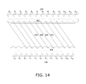
- FIGS. 12-14 are illustrations of sets of detected light beams, in accordance with an embodiment of the present invention.
- FIGS. 15-17 are illustrations of touch detections in different sets of light beams, in accordance with an embodiment of the present invention.
- FIG. 18 is an illustration of touch detections in overlapping light beams being analyzed together, in accordance with an embodiment of the present invention.
- FIG. 19 is an illustration of a set of five touch coordinates being tracked, in accordance with an embodiment of the present invention.
- FIG. 20 is a simplified illustration of a touch screen display surrounded by an exposed light guide frame, in accordance with an embodiment of the present invention.
- FIGS. 21 and 22 are magnified views of a corner of the touch screen of FIG. 20 , in accordance with an embodiment of the present invention.
- FIGS. 23 and 24 are exploded views of the touch screen of FIG. 20 , in accordance with an embodiment of the present invention.
- FIGS. 25-27 are cutaway views of the touch screen of FIG. 20 , illustrating a light beam path from an emitter to crossing above the display to a receiver, in accordance with an embodiment of the present invention
- FIG. 28 is a magnified view of a corner of the touch screen of FIG. 20 viewed from below, with the screen's rear support removed, in accordance with an embodiment of the present invention
- FIG. 29 is a front view of a touch screen display for an all-in-one computer, showing light paths from top to bottom in accordance with an embodiment of the present invention
- FIG. 30 is a front view of the touch screen display of FIG. 29 , showing light paths from left to right in accordance with an embodiment of the present invention
- FIG. 31 is a side view of the touch screen display of FIG. 29 , in accordance with an embodiment of the present invention.
- FIG. 32 is a back view of the touch screen display of FIG. 29 , in accordance with an embodiment of the present invention
- FIG. 33 is an exploded cutaway back view of the touch screen display of FIG. 29 and a PCB strip for LEDs underneath the display, in accordance with an embodiment of the present invention.
- FIG. 34 is an assembled view corresponding to the exploded view of FIG. 33 , in accordance with an embodiment of the present invention.
- touch screen and “touch sensitive surface” include touch sensitive electronic displays and touch surfaces that do not include an electronic display, inter alia, a mouse touchpad as included in many laptop computers and the back cover of a handheld device. They also include airspace enclosed by the rectangular emitter-detector sensor frame provided by the present invention. They also include airspace bordered on only one edge by a linear emitter-detector array whereby light projected into the airspace by the emitters is reflected by the touch object onto the reflectors.
- a light-based touch sensor includes a plurality of infra-red or near infra-red light-emitting diodes (LEDs) arranged along two adjacent edges of a rectangular touch sensitive surface, as defined above, and a plurality of photodiodes (PDs) arranged along the two remaining adjacent edges.
- LEDs infra-red or near infra-red light-emitting diodes
- PDs photodiodes
- FIG. 8 is an illustration of a touch screen, in accordance with an embodiment of the present invention.
- FIG. 8 shows an arrangement of emitters 100 and receivers 200 along opposite edges of touch screen 500 . Emitter lenses 401 and receiver lenses 402 are also shown. Vertical line 907 shows that the emitters 100 are shift-aligned with the receivers 200 and that emitter lenses 401 are shift-aligned with receiver lenses 402 .
- FIG. 8 shows emitters and receivers along only two edges of screen 500 , a similar arrangement of emitters and receivers is present along the remaining two edges as well.
- FIG. 9 is an illustration of a light beam from one emitter projected across a touch screen, in accordance with an embodiment of the present invention.
- FIG. 9 shows how emitter lenses 401 spread the light from each emitter 100 into a wide beam.
- Wide beam 301 is projected by emitter E 5 .
- Receiver lenses 402 provide a wide viewing angle for each receiver 200 , similar in scope to that illustrated by wide beam 301 .
- the emitters 100 are listed as E 0 -E 11 and the receivers 200 are listed as R 0 -R 12 .
- FIGS. 10 and 11 are illustrations of portions of the light beam from one emitter detected by two different receivers, in accordance with an embodiment of the present invention.
- FIG. 10 shows that a portion 302 of a wide beam 301 from each emitter is detected by a respective receiver.
- wide beam 302 is the portion of wide beam 301 detected by receiver R 5 .
- Wide beam 302 is shaped as a parallelogram that spans the width of the emitter lens associated with emitter E 5 and the width of the receiver lens associated with receiver R 5 .
- FIG. 11 shows that another portion 303 of wide beam 301 from each emitter is detected by a different respective receiver.
- wide beam 303 is the portion of wide beam 301 detected by receiver R 6 .
- Wide beam 303 is shaped as a parallelogram that spans the width of the emitter lens associated with emitter E 5 and the width of the receiver lens associated with receiver R 6 .
- FIGS. 12-14 are illustrations of sets of detected light beams, in accordance with an embodiment of the present invention.
- FIG. 12 shows that a set of beams is formed by portion 303 of each emitter beam detected by a respective receiver.
- the set of beams 303 provides continuous detection of an inserted pointer anywhere between the first and last beam 303 , as neighboring beams 303 are adjacent one another.
- FIG. 13 shows that a second set of beams is formed by portion 302 of each emitter beam detected by a different respective receiver than that of beam 303 .
- This set of beams 302 also provides continuous detection of an inserted pointer anywhere between the first and last beam 302 , as neighboring beams 302 are adjacent one another.
- FIG. 14 shows a third set of beams formed by portion 304 of each emitter beam detected by a different respective receiver than those of beams 302 and 303 .
- the beams are grouped into sets of similar beams. Namely, each set is formed by pairing each emitter with a respective one of the receivers, where the offset between each emitter and its respective receiver is the same.
- One advantage of grouping the beams this way is that beams within each group do not intersect. Therefore, when multiple objects are detected within a set of beams the system can identify their relative placement to one another along the axis that the emitters are situated along. In contrast, when analyzing a many-to-many configuration of detection beams in which intersecting beams are analyzed together it is often not possible to determine the relative positions of the detected objects. For example, when two objects a and b are detected by two intersecting beams, it is not known whether a is to the left of b or to the right, because it is unknown if a and b are situated above or below the point of intersection between the two detecting beams. This advantage is elaborated below.
- a plurality of light pulse emitters, E 1 , . . . , E n is arranged such that each emitter, E, transmits light pulses, denoted E( ⁇ 1 ), . . . , E( ⁇ n ), that are directed in directions, ⁇ 1 . . . ⁇ n , outward from an edge of the display and over the display, for detection by n light pulse detectors situated along the perimeter of the display.
- Each light pulse E( ⁇ ) is directed through a lens to create a wide light pulse such that light pulses from neighboring emitters E m and E m+1 , directed at a same angle ⁇ b , are substantially contiguous.
- Each such set of parallel beams is thus denoted E 1 ( ⁇ a ), . . . , E n ( ⁇ a ).
- each set of parallel beams identifies a respective touch location, corresponding to one or more light pulses E i ( ⁇ j ) that is at least partially blocked by the touch, and having (a) a normalized touch value between 0 and 1, denoted W(E i ( ⁇ j )), according to the percentage of blockage of light pulse E i ( ⁇ j ) by the touch, and (b) a respective screen coordinate, denoted X(E i ( ⁇ j ).
- XT ⁇ W ( E i ( ⁇ j ))* X ( E i ( ⁇ j ) (1)
- the system scans additional sets of parallel beams E 1 ( ⁇ a ), E n ( ⁇ a ), E 1 ( ⁇ b ), . . . E n ( ⁇ b ), . . . E 1 ( ⁇ m ), . . . E n ( ⁇ m ).
- the area containing the potential ghosting is identified, and only a subset of each additional set of beams that traverses the potential ghosting area is activated.
- the additional sets of beams resolve the ghosting ambiguity in two stages. The first is explained presently, and the second is described beginning at the section entitled ghost Point Elimination.
- the system activates the sets of additional beams in the table.
- neighboring parallel beams in each set are substantially contiguous.
- a case of two touches is distinguished from a case of one touch if the pattern of touch detections within a series of neighboring parallel beams has more than one peak. This is explained with reference to FIGS. 15-17 .
- FIGS. 15-17 are illustrations of touch detections in different sets of light beams, in accordance with an embodiment of the present invention.
- FIG. 15 illustrates a case in which multiple blocked beams indicate a possible situation of multiple touches.
- the screen is divided into strips having different y-axis coordinates, and for each strip, a segment containing the touch detections is identified.
- the borders of the Y 0 segment are indicated by arrows 905 and 906 .
- Within this segment lie the detections of beams from emitters E 3 -E 7 in beam set ⁇ 1 .
- the detection signal i.e., the normalized touch value between 0 and 1 for each beam within the segment, is indicated above its respective receiver.
- the detections in FIG. 15 are 0.9, 1.0, 1.0, 1.0, 0.1, for beams from emitters E 3 -E 7 , respectively.
- a graph mapping these detections is rendered in the upper portion of FIGS. 15-17 .
- the graph in FIG. 15 shows that the resulting detection signal pattern has only one peak.
- FIG. 16 shows the detections of beams from emitters E 3 -E 7 in beam set ⁇ 2 .
- the resulting detection signal pattern has only one peak.
- FIG. 17 shows the detections of beams from emitters E 5 -E 10 in beam set ⁇ 3 .
- the normalized touch values are 0.6, 1.0, 0.65, 1.0, 1.0, 0.05, respectively, and the resulting detection signal pattern has two peaks, indicating that there is a gap between touches somewhere within the detected wide beam generated by emitter E 7 .
- the interruption between the two peaks is caused by a normalized touch value of 0.65.
- a beam having a normalized touch value of 0.65 when considered alone, indicates that a touch object is present.
- the fact that this touch detection caused a trough in the graph between its two neighboring detections of 1.0 indicates that there are two separate touches in this case.
- FIG. 18 is an illustration of touch detections in overlapping light beams being analyzed together, in accordance with an embodiment of the present invention.
- FIG. 18 shows an instance of ambiguity. In FIG. 18 all detections are combined into the graph at the top of the figure. The graph shows multiple peaks, making it difficult to determine how many touches exist.
- One of the factors contributing to the construction of this graph is that it is unclear how to order the data when combining signals for different intersecting beams, since the touch (or touches) contributing to the blockage can lie anywhere along the beam—namely, above or below any intersection between two beams.
- Embodiments of the present invention resolve these ambiguities by analyzing each set of parallel beams separately. Within each set of beams, the beams do not intersect. Therefore, the ambiguity resulting from intersecting blocked beams does not exist.
- the basic idea behind methods embodying the subject invention is that each touch must affect the detected blocking pattern. If a touch does not contribute to the light blocking in any way, it must be completely hidden by other touches and cannot be detected. Adding or removing a visible touch always alters the blocking pattern, which is a complex nonlinear function of all present touches.
- a blocking pattern is calculated based on a candidate touch combination.
- the problem of multi-touch is thus the “inverse problem”, of finding unknown touch coordinate vectors, x and y , corresponding to a detected blocking pattern, d .
- EQ. (2) enables comparing a predicted blocking pattern, m , based on current candidate touches, x and y , to an actual detected blocking pattern, d , and measuring an error between the predicted blocking pattern and the actual detected blocking pattern.
- the matching error can be used as a metric to perform touch tracking, for moving touch locations.
- the method consists of three steps:
- FIG. 19 is an illustration of a set of five moving touch coordinates being tracked with the above method, in accordance with an embodiment of the present invention.
- a circle in FIG. 19 denotes an actual coordinate
- a cross in FIG. 19 denotes the result of the above method.
- the number of light beams is pruned down to 100 from a total of about 300, by estimating from the model which beams are most likely to contribute to the matching error.
- the optimization used in FIG. 19 is based on steepest descent. Other optimization algorithms, or a particular filter, may be used to perform the optimization step, and to find the best matching touch coordinates, Y and y.
- Optimization of the matching error can alternatively be used to improve touch accuracy in situations where the detection algorithm does not perform well. This may happen close to edges or corners where there are fewer light beams available for coordinate calculation.
- the optimization approach can be extended to cover inaccuracies due to finite beam acquisition time.
- This technique reduces the need for parallel beam acquisition, and consequently reduces total hardware cost of the multi-touch solution.
- a light guide for directing light beams for touch detection over and across the touch screen surface forms an exposed, outer frame of the screen.
- Embodiments of the invention are designed for desktop displays and All-in-One devices where there is little risk of trauma to the screen frame in the course of normal use, as compared to mobile phones, laptops and tablets. Nonetheless, the present invention is applicable to mobile phones, laptops and tablets as well.
- FIG. 20 is a simplified illustration of a touch screen display surrounded by an exposed light guide frame, in accordance with an embodiment of the present invention.
- FIG. 20 shows a touch screen display monitor according to the teachings of the present invention, featuring a display 501 and an exposed surrounding frame 403 that serves as a light guide for directing near-infrared light beams from emitters located underneath the display out over the exposed surface of the display and back under the display to receivers.
- Light guide frame 403 has a very thin profile that extends upward along the outer edges of display 501 .
- display 501 has no stiffeners or structural support elements above its outer edges.
- light guide frame 403 can be manufactured of transparent plastic that makes it seem as if the rendered image extends to the outer edges of the desktop or All-in-One display.
- visible light LEDs are provided to illuminate light guide frame 403 .
- the system identifies the color of the outermost pixels on the display and illuminates light guide frame 403 with a similar color so that the frame is adapted to visually blend into the rendered image.
- FIGS. 21 and 22 are magnified views of a corner of the touch screen of FIG. 20 , in accordance with an embodiment of the present invention.
- Frame 403 extends above display 501 , but is very thin, so it adds very little to the width and length of the device.
- Frame 403 extends above display 501 in order to project and receive the near-infrared light beams above and across the screen surface.
- FIG. 22 shows an enlarged view of one corner of the touch screen of FIG. 20 , viewed from outside frame 403 .
- Two internally reflective surfaces, 404 and 405 are shown for directing the near-infrared light beams from underneath display 501 across the screen surface.
- FIGS. 23 and 24 are exploded views of the touch screen of FIG. 20 , in accordance with an embodiment of the present invention.
- display 501 is inserted into frame 403 from above; from below, PCB 502 on which the near-infrared emitters and receivers are mounted is inserted into frame 403 as are lenses 407 .
- Frame 403 is divided into an upper cavity and a lower cavity by floor 803 .
- Display 501 is housed in the upper cavity, and PCB 502 and lenses 407 are housed in the lower cavity.
- display 501 has some exposed electronics or mechanical stiffeners along one edge.
- the exposed electronics or mechanical stiffeners are covered by light guide 406 that transmits light exiting the upper edge of light guide 403 over the exposed electronics or mechanical stiffeners.
- the display pixels extend to all four edges of display 501 . In these other embodiments, light guide 406 is not used.
- the touch screen is supported and kept rigid by rear support 802 .
- FIG. 24 shows light guide frame 403 , PCB 502 , emitter and receiver lenses 407 and rear support 802 .
- PCB 502 is formed by four PCB strips situated along the four edges of frame 403 .
- Each PCB strip has a row of either emitters or receivers mounted on its underside, not shown in FIG. 24 .
- FIGS. 25-27 are cutaway views of the touch screen of FIG. 20 , illustrating a light beam path from an emitter crossing above the display to a receiver, in accordance with an embodiment of the present invention.
- FIG. 25 shows light guide frame 403 , its upper and lower internally reflective surfaces 404 and 405 and floor 803 .
- Display 501 is above floor 803 and PCB 502 is mounted on the underside of floor 803 .
- a light emitter 102 is shown mounted on PCB 502 .
- the path of light beam 305 is illustrated entering lens 407 , being reflected by surfaces 405 and 404 , through light guide 406 , and out across the upper surface of screen 501 .
- FIG. 26 shows the path of light beam 305 toward receiver 202 .
- light guide 406 is situated along only one edge of display 501 .
- light guide 406 is present in FIG. 25 and absent in FIG. 26 .
- FIG. 27 shows the path of light beam 305 across the display, from an emitter to a receiver.
- light guide 406 is situated along only one edge of display 501 the light beam is wide and reaches multiple receivers.
- FIG. 27 is a simplified illustration of only the functionality of light guide frame 403 .
- FIG. 28 is a magnified view of a corner of the touch screen of FIG. 20 viewed from below, with the screen's rear support removed, in accordance with an embodiment of the present invention.
- FIG. 28 shows the underside of light frame 403 in the touch screen of FIG. 20 , and two PCBs 502 , one on which emitters 103 are mounted and the other on which receivers 203 are mounted. Each emitter and receiver has a respective lens 407 .
- Processor 503 shown mounted on PCB 502 , is coupled with said LEDs 103 and PDs 203 .
- light guide frame 403 is transparent, and furthermore, visible-light LEDs are mounted within frame 403 , e.g., on PCB 502 , to illuminate the frame, under certain conditions.
- the frame is illuminated to notify the user, e.g., upon receiving an email or a video call the frame is illuminated a specific color.
- the infrared light used for touch detection is transmitted through frame 403 by total internal reflection (TIR).
- TIR total internal reflection
- the object absorbs a portion of the transmitted infrared light. This absorption is detected as a reduction in expected light at the receivers. Significantly, this reduction occurs only to light beams along one axis, not both axes, when a user touches one edge of the frame.
- a touch on the frame is distinguished from a touch on the screen which causes detections on two axes.
- This touch gesture namely, a touch or tap on the outside of frame 403
- a touch or tap on the outside of frame 403 is used in some embodiments to activate a function, e.g., to open the Charms bar in certain Windows operating systems.
- WINDOWS® is a registered trademark of Microsoft Corporation.
- this gesture opens the email or the video call.
- a tap on the frame wakes up the computer from sleep mode. This can be communicated to the user by illuminating the frame in response to the tap.
- swipe gesture along an outer edge of frame 403 is also detectable because as the user glides his finger along the edge his finger absorbs infrared light beams from different emitters or receivers. Therefore, swipe gestures are also enabled on the outer perimeter of the frame.
- An advantage of the touch screen assembly described above is the ability to accommodate light-based touch sensitivity for curved display screens.
- a technical challenge arises when trying to emit light from one edge of a curved screen to an opposite edge.
- use of a single plane to direct light over a curved screen leads to touch detection errors due to the screen dipping underneath the plane, as shown in FIG. 31 below.
- the frame that guides the emitted light is generally only able to guide the light at a fixed orientation relative to the screen surface.
- the frame is oriented so as to guide the light emitted by the LEDs along light paths that travel across the screen in segments that follow the contour of the display screen, which are incident upon and reflect off of the display screen one or more times, while crossing the screen.
- FIG. 29 is a front view of a touch screen display 804 for an all-in-one computer, showing light paths 310 - 312 from top to bottom in accordance with an embodiment of the present invention.
- the screen surface of FIG. 29 has a curved cross-section in the left-to-right direction and a straight cross-section in the top-to-bottom direction. In one embodiment of the present invention, the screen has a 34′′ diagonal.
- emitted light travels from the top edge of the screen along light paths that may have one or more reflections off of the screen surface until they reach the bottom edge.
- the light emitted from the top edge is directed parallel to the screen surface.
- the light oriented parallel to the top-to-bottom dimension reaches the opposite edge in a straight line.
- the light that is skewed towards the left or right edges encounters one or more reflections off of the screen surface, depending on the amount of the skew, due to the curvature of the surface in the left-to-right direction.
- FIG. 29 shows three top-to-bottom light paths; namely, a center light path 311 with no reflections, a light path 312 skewed leftward with one reflection, and a light path 310 skewed rightward with two reflections.
- FIG. 29 shows emitter location 105 and receiver locations 208 - 210 .
- FIG. 30 is a front view of touch screen display 804 of FIG. 29 , showing light paths 306 - 309 from left to right in accordance with an embodiment of the present invention.
- the light paths shown in FIG. 30 reflect multiple times off of the screen surface, following the contour of the surface, and eventually make their way to the right edge.
- FIG. 30 shows emitter location 104 and receiver locations 204 - 207 .
- left-to-right light paths could have been generated as straight lines, since the left and right edges are co-planar in the screen of FIG. 30 , use of such light paths would, however, lead to touch detection errors, as explained in what follows.
- FIG. 31 is a side view of the touch screen display of FIG. 29 , in accordance with an embodiment of the present invention.
- FIG. 31 shows imaginary straight line paths 908 - 911 and an imaginary finger 912 blocking the paths.
- FIG. 31 also shows emitter location 104 and receiver location 205 .
- FIG. 31 also shows light path 313 which follows the contour of the curved screen surface, and emitter locations 106 - 108 at the left edge of imaginary straight line paths 909 - 911 , respectively.
- a first error designated “false positive” in FIG.
- FIG. 32 is a back view of the touch screen display of FIG. 29 , in accordance with an embodiment of the present invention.
- FIG. 33 is an exploded cutaway back view of the touch screen display of FIG. 29 and a PCB strip 504 for LEDs underneath the display, in accordance with an embodiment of the present invention. Also shown in FIG. 33 are lenses 409 for the LEDs that guide light from the LEDs into light guide frame 403 , floor 803 and LED lenses 410 along the left edge of the screen.
- FIG. 34 is an assembled view corresponding to the exploded view of FIG. 33 , in accordance with an embodiment of the present invention.
Abstract
Description
XT=ΣW(E i(θj))*X(E i(θj) (1)
When an unambiguous pattern of one or more touches is detected, an interpolation of touch locations from even only a few sets of parallel beams, e.g., 2-6 sets, provides a highly accurate touch coordinate. The fewer touch locations required for interpolation the faster the scanning speed and/or the lower the power required per screen scan. When the possibility of ghosting is determined present in one or more locations on the screen, the system scans additional sets of parallel beams E1(θa), En(θa), E1(θb), . . . En(θb), . . . E1(θm), . . . En(θm). In some embodiments, the area containing the potential ghosting is identified, and only a subset of each additional set of beams that traverses the potential ghosting area is activated. The additional sets of beams resolve the ghosting ambiguity in two stages. The first is explained presently, and the second is described beginning at the section entitled Ghost Point Elimination.
| Start and end emitters whose | |
| beams cross the identified segment | |
| Strip y-coordinate | Θ1 Set | Θ2 Set | Θ3 Set | . . . | Θn Set |
| 0 | {E3-E7} | {E3-E7} | {E5-E10} | . . . | . . . |
| 1 | . . . | . . . | . . . | . . . | . . . |
| . . . | . . . | . . . | . . . | . . . | . . . |
| Max y | . . . | . . . | . . . | . . . | . . . |
where
e=Σ k=1 N |d k −m k|, (3)
where
Tracking
-
- 1. Update touch coordinates,
x =(x1, . . . , xn) andv =(v1, . . . , vn) of the touch coordinates, to form a new set of candidate coordinates. - 2. Perform an optimization on the touch coordinates,
x andy , to find the set which minimizes the matching error. - 3. Update the touch coordinates,
x andy , and the speed estimates.
- 1. Update touch coordinates,
Each touch is assumed to be moving, and the sequence of measuring the beam data is included in the model for m.
Claims (11)
Priority Applications (11)
| Application Number | Priority Date | Filing Date | Title |
|---|---|---|---|
| US14/588,462 US9207800B1 (en) | 2014-09-23 | 2015-01-02 | Integrated light guide and touch screen frame and multi-touch determination method |
| PCT/US2015/047730 WO2016048590A1 (en) | 2014-09-23 | 2015-08-31 | Integrated light guide and touch screen frame and multi-touch determination method |
| US14/960,369 US9645679B2 (en) | 2014-09-23 | 2015-12-05 | Integrated light guide and touch screen frame |
| US15/588,646 US10282034B2 (en) | 2012-10-14 | 2017-05-07 | Touch sensitive curved and flexible displays |
| US15/616,106 US10585530B2 (en) | 2014-09-23 | 2017-06-07 | Optical proximity sensor |
| US16/365,662 US10949027B2 (en) | 2012-10-14 | 2019-03-26 | Interactive virtual display |
| US16/775,057 US10928957B2 (en) | 2012-10-14 | 2020-01-28 | Optical proximity sensor |
| US17/176,033 US11782557B2 (en) | 2012-10-14 | 2021-02-15 | User interface |
| US17/198,273 US11714509B2 (en) | 2012-10-14 | 2021-03-11 | Multi-plane reflective sensor |
| US17/985,891 US20230088402A1 (en) | 2012-10-14 | 2022-11-13 | Touch sensitive curved and flexible displays |
| US18/449,826 US20230384896A1 (en) | 2012-10-14 | 2023-08-15 | User interface |
Applications Claiming Priority (2)
| Application Number | Priority Date | Filing Date | Title |
|---|---|---|---|
| US201462054353P | 2014-09-23 | 2014-09-23 | |
| US14/588,462 US9207800B1 (en) | 2014-09-23 | 2015-01-02 | Integrated light guide and touch screen frame and multi-touch determination method |
Related Parent Applications (1)
| Application Number | Title | Priority Date | Filing Date |
|---|---|---|---|
| US15/000,815 Continuation-In-Part US9921661B2 (en) | 2012-10-14 | 2016-01-19 | Optical proximity sensor and associated user interface |
Related Child Applications (1)
| Application Number | Title | Priority Date | Filing Date |
|---|---|---|---|
| US14/960,369 Continuation US9645679B2 (en) | 2012-10-14 | 2015-12-05 | Integrated light guide and touch screen frame |
Publications (1)
| Publication Number | Publication Date |
|---|---|
| US9207800B1 true US9207800B1 (en) | 2015-12-08 |
Family
ID=54708274
Family Applications (2)
| Application Number | Title | Priority Date | Filing Date |
|---|---|---|---|
| US14/588,462 Active US9207800B1 (en) | 2012-10-14 | 2015-01-02 | Integrated light guide and touch screen frame and multi-touch determination method |
| US14/960,369 Active US9645679B2 (en) | 2012-10-14 | 2015-12-05 | Integrated light guide and touch screen frame |
Family Applications After (1)
| Application Number | Title | Priority Date | Filing Date |
|---|---|---|---|
| US14/960,369 Active US9645679B2 (en) | 2012-10-14 | 2015-12-05 | Integrated light guide and touch screen frame |
Country Status (2)
| Country | Link |
|---|---|
| US (2) | US9207800B1 (en) |
| WO (1) | WO2016048590A1 (en) |
Cited By (24)
| Publication number | Priority date | Publication date | Assignee | Title |
|---|---|---|---|---|
| USD776665S1 (en) * | 2015-02-05 | 2017-01-17 | Neonode Inc. | Light guide frame |
| USD776666S1 (en) * | 2015-02-05 | 2017-01-17 | Neonode Inc. | Curved light guide frame |
| CN107340900A (en) * | 2016-04-29 | 2017-11-10 | 北京小米移动软件有限公司 | A kind of mobile terminal center and mobile terminal |
| WO2018182476A1 (en) * | 2017-03-28 | 2018-10-04 | Flatfrog Laboratories Ab | Touch sensing apparatus and method for assembly |
| US10282034B2 (en) | 2012-10-14 | 2019-05-07 | Neonode Inc. | Touch sensitive curved and flexible displays |
| KR20190092411A (en) * | 2016-12-07 | 2019-08-07 | 플라트프로그 라보라토리즈 에이비 | Improved touch device |
| US10730216B2 (en) * | 2015-08-31 | 2020-08-04 | Uniplas Enterprises Pte. Ltd. | Injection moulding apparatus and method for injection moulding and IR-compatible display frame |
| US10791639B2 (en) * | 2018-07-13 | 2020-09-29 | Hand Held Products, Inc. | Methods, systems, and apparatuses for preventing moisture accumulation on a display screen |
| US11016605B2 (en) | 2017-03-22 | 2021-05-25 | Flatfrog Laboratories Ab | Pen differentiation for touch displays |
| US11029783B2 (en) * | 2015-02-09 | 2021-06-08 | Flatfrog Laboratories Ab | Optical touch system comprising means for projecting and detecting light beams above and inside a transmissive panel |
| US11086445B2 (en) * | 2017-09-29 | 2021-08-10 | Sk Telecom Co., Lid. | Device and method for controlling touch display, and touch display system |
| US11126295B2 (en) * | 2015-06-07 | 2021-09-21 | Apple Inc. | Devices and methods for processing touch inputs |
| US11182023B2 (en) | 2015-01-28 | 2021-11-23 | Flatfrog Laboratories Ab | Dynamic touch quarantine frames |
| US11256371B2 (en) | 2017-09-01 | 2022-02-22 | Flatfrog Laboratories Ab | Optical component |
| US11301089B2 (en) | 2015-12-09 | 2022-04-12 | Flatfrog Laboratories Ab | Stylus identification |
| US11379048B2 (en) | 2012-10-14 | 2022-07-05 | Neonode Inc. | Contactless control panel |
| US11474644B2 (en) | 2017-02-06 | 2022-10-18 | Flatfrog Laboratories Ab | Optical coupling in touch-sensing systems |
| US11567610B2 (en) | 2018-03-05 | 2023-01-31 | Flatfrog Laboratories Ab | Detection line broadening |
| US11669210B2 (en) * | 2020-09-30 | 2023-06-06 | Neonode Inc. | Optical touch sensor |
| US11709568B2 (en) | 2020-02-25 | 2023-07-25 | Promethean Limited | Convex interactive touch displays and related systems and methods |
| US11733808B2 (en) | 2012-10-14 | 2023-08-22 | Neonode, Inc. | Object detector based on reflected light |
| US11842014B2 (en) | 2019-12-31 | 2023-12-12 | Neonode Inc. | Contactless touch input system |
| US11893189B2 (en) | 2020-02-10 | 2024-02-06 | Flatfrog Laboratories Ab | Touch-sensing apparatus |
| US11943563B2 (en) | 2019-01-25 | 2024-03-26 | FlatFrog Laboratories, AB | Videoconferencing terminal and method of operating the same |
Families Citing this family (5)
| Publication number | Priority date | Publication date | Assignee | Title |
|---|---|---|---|---|
| KR20180037749A (en) * | 2016-10-05 | 2018-04-13 | 에스프린팅솔루션 주식회사 | Display apparatus |
| WO2018097943A1 (en) * | 2016-11-22 | 2018-05-31 | Neonode Inc. | Touch sensitive curved and flexible displays |
| WO2020236071A1 (en) * | 2019-05-22 | 2020-11-26 | Flatfrog Laboratories Ab | Touch sensing apparatus |
| US20230393692A1 (en) * | 2020-10-19 | 2023-12-07 | Flatfrog Laboratories Ab | A touch sensing apparatus |
| JP2023527900A (en) * | 2020-12-31 | 2023-06-30 | 広州視源電子科技股▲分▼有限公司 | Touch frame unit and interactive intelligent panel |
Citations (177)
| Publication number | Priority date | Publication date | Assignee | Title |
|---|---|---|---|---|
| US4243879A (en) | 1978-04-24 | 1981-01-06 | Carroll Manufacturing Corporation | Touch panel with ambient light sampling |
| US4267443A (en) | 1978-04-24 | 1981-05-12 | Carroll Manufacturing Corporation | Photoelectric input apparatus |
| US4301447A (en) | 1979-12-12 | 1981-11-17 | Sperry Corporation | Scan control for light beam position indicator |
| WO1986000447A1 (en) | 1984-06-18 | 1986-01-16 | Amp Incorporated | Touch input device having digital ambient light sampling |
| WO1986000446A1 (en) | 1984-06-18 | 1986-01-16 | Amp Incorporated | Touch input device |
| US4588258A (en) | 1983-09-12 | 1986-05-13 | Minnesota Mining And Manufacturing Company | Cube-corner retroreflective articles having wide angularity in multiple viewing planes |
| US4641426A (en) | 1985-06-21 | 1987-02-10 | Associated Enterprises, Inc. | Surface mount compatible connector system with mechanical integrity |
| US4672364A (en) | 1984-06-18 | 1987-06-09 | Carroll Touch Inc | Touch input device having power profiling |
| US4703316A (en) | 1984-10-18 | 1987-10-27 | Tektronix, Inc. | Touch panel input apparatus |
| US4761637A (en) | 1984-06-18 | 1988-08-02 | Carroll Touch Inc. | Touch input device |
| US4928094A (en) | 1988-01-25 | 1990-05-22 | The Boeing Company | Battery-operated data collection apparatus having an infrared touch screen data entry device |
| US5036187A (en) | 1989-05-08 | 1991-07-30 | Dowa Mining Co., Ltd. | Photodetecting circuit with compensated integration signal |
| US5162783A (en) | 1990-07-23 | 1992-11-10 | Akzo N.V. | Infrared touch screen device for a video monitor |
| US5194863A (en) | 1989-04-10 | 1993-03-16 | International Business Machines Corporation | Touch panel display |
| US5220409A (en) | 1988-12-19 | 1993-06-15 | Amp Incorporated | Light beam detection utilizing hologram |
| EP0601651A1 (en) | 1992-12-10 | 1994-06-15 | Koninklijke Philips Electronics N.V. | Optical touch tablet based on sector cross bearing |
| US5414413A (en) | 1988-06-14 | 1995-05-09 | Sony Corporation | Touch panel apparatus |
| US5559727A (en) | 1994-02-24 | 1996-09-24 | Quad Systems Corporation | Apparatus and method for determining the position of a component prior to placement |
| US5577733A (en) | 1994-04-08 | 1996-11-26 | Downing; Dennis L. | Targeting system |
| US5603053A (en) | 1993-05-10 | 1997-02-11 | Apple Computer, Inc. | System for entering data into an active application currently running in the foreground by selecting an input icon in a palette representing input utility |
| US5729250A (en) | 1995-05-08 | 1998-03-17 | International Business Machines Corporation | Front cover assembly for a touch sensitive device |
| US5748185A (en) | 1996-07-03 | 1998-05-05 | Stratos Product Development Group | Touchpad with scroll and pan regions |
| US5825352A (en) | 1996-01-04 | 1998-10-20 | Logitech, Inc. | Multiple fingers contact sensing method for emulating mouse buttons and mouse operations on a touch sensor pad |
| US5889236A (en) | 1992-06-08 | 1999-03-30 | Synaptics Incorporated | Pressure sensitive scrollbar feature |
| US5914709A (en) | 1997-03-14 | 1999-06-22 | Poa Sana, Llc | User input device for a computer system |
| US5936615A (en) | 1996-09-12 | 1999-08-10 | Digital Equipment Corporation | Image-based touchscreen |
| US5943044A (en) | 1996-08-05 | 1999-08-24 | Interlink Electronics | Force sensing semiconductive touchpad |
| JPH11232024A (en) | 1998-02-13 | 1999-08-27 | Alpine Electron Inc | Optical position detector |
| US5946134A (en) | 1993-10-20 | 1999-08-31 | Minnesota Mining & Manufacturing Company | Raised structure retroreflective article |
| US6010061A (en) | 1998-03-27 | 2000-01-04 | Micron Custom Manufacturing Services Inc. | Reflow soldering method |
| US6091405A (en) | 1992-06-30 | 2000-07-18 | International Business Machines Corporation | Input device |
| US20010002694A1 (en) | 1998-08-18 | 2001-06-07 | Fujitsu Limited | Optical scanning-type touch panel |
| US20010022579A1 (en) | 2000-03-16 | 2001-09-20 | Ricoh Company, Ltd. | Apparatus for inputting coordinates |
| US20010026268A1 (en) | 2000-03-31 | 2001-10-04 | Ricoh Company, Ltd. | Coordiante input and detection device and information display and input apparatus |
| US20010028344A1 (en) | 1998-11-20 | 2001-10-11 | Fujitsu Limited | Optical scanning-type touch panel |
| US6333735B1 (en) | 1999-03-16 | 2001-12-25 | International Business Machines Corporation | Method and apparatus for mouse positioning device based on infrared light sources and detectors |
| US20010055006A1 (en) | 1999-02-24 | 2001-12-27 | Fujitsu Limited | Optical scanning-type touch panel |
| US6340979B1 (en) | 1997-12-04 | 2002-01-22 | Nortel Networks Limited | Contextual gesture interface |
| US6362468B1 (en) | 1999-06-10 | 2002-03-26 | Saeilo Japan, Inc. | Optical unit for detecting object and coordinate input apparatus using same |
| US20020067348A1 (en) | 1999-12-02 | 2002-06-06 | Masters Timothy E. | Apparatus and method to improve resolution of infrared touch systems |
| US6421042B1 (en) | 1998-06-09 | 2002-07-16 | Ricoh Company, Ltd. | Coordinate position inputting/detecting device, a method for inputting/detecting the coordinate position, and a display board system |
| US20020109843A1 (en) | 2001-02-13 | 2002-08-15 | Applied Materials, Inc. | Method and system for registering fiducials employing backlighting techniques |
| US20020175900A1 (en) | 2001-04-04 | 2002-11-28 | Armstrong Donald B. | Touch input system |
| US20030231308A1 (en) | 2001-11-21 | 2003-12-18 | Granger Edward M. | Refractive-diffractive spectrometer |
| US20030234346A1 (en) | 2002-06-21 | 2003-12-25 | Chi-Lei Kao | Touch panel apparatus with optical detection for location |
| US6690365B2 (en) | 2001-08-29 | 2004-02-10 | Microsoft Corporation | Automatic scrolling |
| US6690387B2 (en) | 2001-12-28 | 2004-02-10 | Koninklijke Philips Electronics N.V. | Touch-screen image scrolling system and method |
| US20040046960A1 (en) | 2002-09-11 | 2004-03-11 | Wagner Mark Donald | Lens blank alignment and blocking device and method |
| US6707449B2 (en) | 2000-08-30 | 2004-03-16 | Microsoft Corporation | Manual controlled scrolling |
| US6757002B1 (en) | 1999-11-04 | 2004-06-29 | Hewlett-Packard Development Company, L.P. | Track pad pointing device with areas of specialized function |
| US6762077B2 (en) | 2001-05-11 | 2004-07-13 | Melexis Nv | Integrated sensor packages and methods of making the same |
| US20040140961A1 (en) | 2003-01-17 | 2004-07-22 | Eastman Kodak Company | Oled display and touch screen |
| US6788292B1 (en) | 1998-02-25 | 2004-09-07 | Sharp Kabushiki Kaisha | Display device |
| US6803906B1 (en) | 2000-07-05 | 2004-10-12 | Smart Technologies, Inc. | Passive touch system and method of detecting user input |
| US20040201579A1 (en) | 2003-04-08 | 2004-10-14 | Poa Sana, Inc., A California Corporation | Apparatus and method for a data input device using a light lamina screen and an optical position digitizer |
| US6836367B2 (en) | 2001-02-28 | 2004-12-28 | Japan Aviation Electronics Industry, Limited | Optical touch panel |
| US6864882B2 (en) | 2000-05-24 | 2005-03-08 | Next Holdings Limited | Protected touch panel display system |
| US20050073508A1 (en) | 1998-08-18 | 2005-04-07 | Digital Ink, Inc., A Massachusetts Corporation | Tracking motion of a writing instrument |
| US20050104860A1 (en) | 2002-03-27 | 2005-05-19 | Nellcor Puritan Bennett Incorporated | Infrared touchframe system |
| US20050122308A1 (en) | 2002-05-28 | 2005-06-09 | Matthew Bell | Self-contained interactive video display system |
| US20050174473A1 (en) | 1999-11-18 | 2005-08-11 | Color Kinetics, Inc. | Photography methods and systems |
| US6947032B2 (en) | 2003-03-11 | 2005-09-20 | Smart Technologies Inc. | Touch system and method for determining pointer contacts on a touch surface |
| US6954197B2 (en) | 2002-11-15 | 2005-10-11 | Smart Technologies Inc. | Size/scale and orientation determination of a pointer in a camera-based touch system |
| US6972834B1 (en) | 2000-12-11 | 2005-12-06 | Mitsubishi Denki Kabushiki Kaisha | Optical distance sensor |
| US6972401B2 (en) | 2003-01-30 | 2005-12-06 | Smart Technologies Inc. | Illuminated bezel and touch system incorporating the same |
| US20050271319A1 (en) | 2004-06-04 | 2005-12-08 | National Semiconductor Corporation, A Delaware Corporation | Apparatus and method for a molded waveguide for use with touch screen displays |
| US20060001654A1 (en) | 2004-06-30 | 2006-01-05 | National Semiconductor Corporation | Apparatus and method for performing data entry with light based touch screen displays |
| US20060018586A1 (en) | 2002-11-01 | 2006-01-26 | Kinzo Kishida | Distributed optical fiber sensor system |
| US7030861B1 (en) | 2001-02-10 | 2006-04-18 | Wayne Carl Westerman | System and method for packing multi-touch gestures onto a hand |
| US20060132454A1 (en) | 2004-12-16 | 2006-06-22 | Deng-Peng Chen | Systems and methods for high resolution optical touch position systems |
| US20060161871A1 (en) | 2004-07-30 | 2006-07-20 | Apple Computer, Inc. | Proximity detector in handheld device |
| US20060161870A1 (en) | 2004-07-30 | 2006-07-20 | Apple Computer, Inc. | Proximity detector in handheld device |
| US20060229509A1 (en) | 2005-03-01 | 2006-10-12 | Ammar Al-Ali | Multiple wavelength sensor attachment |
| US7133032B2 (en) | 2003-04-24 | 2006-11-07 | Eastman Kodak Company | OLED display and touch screen |
| US20070024598A1 (en) | 2005-07-29 | 2007-02-01 | Miller Jeffrey N | Methods and systems for detecting selections on a touch screen display |
| US7176905B2 (en) | 2003-02-19 | 2007-02-13 | Agilent Technologies, Inc. | Electronic device having an image-based data input system |
| US7184030B2 (en) | 2002-06-27 | 2007-02-27 | Smart Technologies Inc. | Synchronization of cameras in camera-based touch system to enhance position determination of fast moving objects |
| US20070052693A1 (en) | 2005-08-29 | 2007-03-08 | Pioneer Corporation | Coordinate position detecting apparatus and control method thereof |
| US20070084989A1 (en) | 2003-09-22 | 2007-04-19 | Koninklijke Philips Electronics N.V. | Light guide touch screen |
| US20070146318A1 (en) | 2004-03-11 | 2007-06-28 | Mobisol Inc. | Pointing device with an integrated optical structure |
| US20070152984A1 (en) | 2005-12-30 | 2007-07-05 | Bas Ording | Portable electronic device with multi-touch input |
| US20070176908A1 (en) | 2004-04-01 | 2007-08-02 | Power 2B, Inc. | Control apparatus |
| WO2008004103A2 (en) | 2006-07-06 | 2008-01-10 | Flatfrog Laboratories Ab | Optical touchpad with three-dimensional position determination |
| US20080008472A1 (en) | 2002-11-05 | 2008-01-10 | Dress William B | Distribution optical elements and compound collecting lenses for broadcast optical interconnect |
| US20080012850A1 (en) | 2003-12-30 | 2008-01-17 | The Trustees Of The Stevens Institute Of Technology | Three-Dimensional Imaging System Using Optical Pulses, Non-Linear Optical Mixers And Holographic Calibration |
| US20080013913A1 (en) | 2006-07-12 | 2008-01-17 | Lumio | Optical touch screen |
| US7339580B2 (en) | 1998-01-26 | 2008-03-04 | Apple Inc. | Method and apparatus for integrating manual input |
| US20080055273A1 (en) | 2006-09-06 | 2008-03-06 | Scott Forstall | Web-Clip Widgets on a Portable Multifunction Device |
| US20080056068A1 (en) | 2006-08-31 | 2008-03-06 | Egalax_Empia Technology, Inc. | Apparatus and method for detecting position, and touch panel using the same |
| US7352940B2 (en) | 2005-02-07 | 2008-04-01 | Rpo Pty Limited | Waveguide design incorporating reflective optics |
| EP1906632A2 (en) | 2006-09-29 | 2008-04-02 | LG Electronics Inc. | Mobile phone with illuminated touch screen |
| US20080080811A1 (en) | 2006-10-03 | 2008-04-03 | National Semiconductor Corporation, A Delaware Corporation | Apparatus and method for an improved lens structure for polymer wave guides which maximizes free space light coupling |
| US20080093542A1 (en) | 2006-07-12 | 2008-04-24 | Lumio Inc. | Device and Method for Optical Touch Panel Illumination |
| US20080100593A1 (en) | 2006-10-31 | 2008-05-01 | Peter Skillman | Light sensitive display interface for computing devices |
| US7372456B2 (en) | 2004-07-07 | 2008-05-13 | Smart Technologies Inc. | Method and apparatus for calibrating an interactive touch system |
| US20080117183A1 (en) | 2006-11-20 | 2008-05-22 | Samsung Electronics Co., Ltd | Touch screen using image sensor |
| US20080122792A1 (en) | 2006-11-27 | 2008-05-29 | Microsoft Corporation | Communication with a Touch Screen |
| US20080122796A1 (en) | 2006-09-06 | 2008-05-29 | Jobs Steven P | Touch Screen Device, Method, and Graphical User Interface for Determining Commands by Applying Heuristics |
| US20080122803A1 (en) | 2006-11-27 | 2008-05-29 | Microsoft Corporation | Touch Sensing Using Shadow and Reflective Modes |
| US20080158174A1 (en) | 2007-01-03 | 2008-07-03 | Apple Computer, Inc. | Storing baseline information in EEPROM |
| US20080221711A1 (en) | 2004-03-06 | 2008-09-11 | Michael Trainer | Methods and apparatus for determining characteristics of particles |
| US7429706B2 (en) | 2002-12-27 | 2008-09-30 | Wai Ho | Interactive IR electronic white board |
| US20080259053A1 (en) | 2007-04-11 | 2008-10-23 | John Newton | Touch Screen System with Hover and Click Input Methods |
| US20080273019A1 (en) | 2007-05-02 | 2008-11-06 | National Semiconductor Corporation | Shadow detection in optical touch sensor through the linear combination of optical beams and grey-scale determination of detected shadow edges |
| WO2008133941A2 (en) | 2007-04-25 | 2008-11-06 | Tyco Electronics Corporation | A touchscreen for detecting multiple touches |
| US20080278460A1 (en) | 2007-05-11 | 2008-11-13 | Rpo Pty Limited | Transmissive Body |
| US20080297487A1 (en) | 2007-01-03 | 2008-12-04 | Apple Inc. | Display integrated photodiode matrix |
| US20090009944A1 (en) | 2007-07-05 | 2009-01-08 | Sony Corporation | Electronic apparatus |
| US20090027357A1 (en) | 2007-07-23 | 2009-01-29 | Smart Technologies, Inc. | System and method of detecting contact on a display |
| US20090058833A1 (en) | 2007-08-30 | 2009-03-05 | John Newton | Optical Touchscreen with Improved Illumination |
| US20090066673A1 (en) | 2007-09-07 | 2009-03-12 | Molne Anders L | Integrated force sensitive lens and software |
| US20090096994A1 (en) | 2007-10-10 | 2009-04-16 | Gerard Dirk Smits | Image projector with reflected light tracking |
| US20090102815A1 (en) | 2007-10-23 | 2009-04-23 | Nitto Denko Corporation | Optical waveguide for touch panel and touch panel using the same |
| US20090135162A1 (en) | 2005-03-10 | 2009-05-28 | Koninklijke Philips Electronics, N.V. | System and Method For Detecting the Location, Size and Shape of Multiple Objects That Interact With a Touch Screen Display |
| US20090139778A1 (en) | 2007-11-30 | 2009-06-04 | Microsoft Corporation | User Input Using Proximity Sensing |
| US20090153519A1 (en) | 2007-12-17 | 2009-06-18 | Suarez Rovere Victor Manuel | Method and apparatus for tomographic touch imaging and interactive system using same |
| US20090167724A1 (en) | 2007-12-28 | 2009-07-02 | International Business Machines Corporation | Optical Touch Panel |
| US20100002291A1 (en) | 2006-08-18 | 2010-01-07 | Hiroya Fukuyama | Lighting system, method of lighting, and scanning optical microscope |
| US20100023895A1 (en) * | 2008-07-25 | 2010-01-28 | Microsoft Corporation | Touch Interaction with a Curved Display |
| WO2010015408A1 (en) | 2008-08-07 | 2010-02-11 | Owen Drumm | Method and apparatus for detecting a multitouch event in an optical touch-sensitive device |
| US20100079407A1 (en) | 2008-09-26 | 2010-04-01 | Suggs Bradley N | Identifying actual touch points using spatial dimension information obtained from light transceivers |
| US20100079412A1 (en) | 2008-10-01 | 2010-04-01 | Quanta Computer Inc. | Calibrating apparatus and method |
| US20100079409A1 (en) | 2008-09-29 | 2010-04-01 | Smart Technologies Ulc | Touch panel for an interactive input system, and interactive input system incorporating the touch panel |
| US20100095234A1 (en) | 2008-10-07 | 2010-04-15 | Research In Motion Limited | Multi-touch motion simulation using a non-touch screen computer input device |
| US20100149073A1 (en) | 2008-11-02 | 2010-06-17 | David Chaum | Near to Eye Display System and Appliance |
| US20100289755A1 (en) | 2009-05-15 | 2010-11-18 | Honh Kong Applied Science and Technology Research Institute Co., Ltd. | Touch-Sensing Liquid Crystal Display |
| US20100295821A1 (en) | 2009-05-20 | 2010-11-25 | Tom Chang | Optical touch panel |
| WO2010134865A1 (en) | 2009-05-18 | 2010-11-25 | Flatfrog Laboratories Ab | Determining the location of an object on a touch surface |
| US20100302185A1 (en) | 2009-06-01 | 2010-12-02 | Perceptive Pixel Inc. | Touch Sensing |
| US20110043826A1 (en) | 2009-08-21 | 2011-02-24 | Seiko Epson Corporation | Optical information input device, electronic device with optical input function, and optical information input method |
| US20110044579A1 (en) | 2009-08-21 | 2011-02-24 | Microsoft Corporation | Efficient collimation of light with optical wedge |
| US20110050650A1 (en) | 2009-09-01 | 2011-03-03 | Smart Technologies Ulc | Interactive input system with improved signal-to-noise ratio (snr) and image capture method |
| US20110050639A1 (en) | 2009-09-02 | 2011-03-03 | Lenovo (Singapore) Pte, Ltd. | Apparatus, method, and system for touch and gesture detection |
| US20110057906A1 (en) | 2009-09-09 | 2011-03-10 | Stmicroelectronics (Research & Development) Limited | Pointing devices |
| US20110063214A1 (en) | 2008-09-05 | 2011-03-17 | Knapp David J | Display and optical pointer systems and related methods |
| US20110074736A1 (en) | 2009-09-25 | 2011-03-31 | Hideya Takakura | Optical pointing device and electronic equipments |
| US20110075418A1 (en) | 2009-09-25 | 2011-03-31 | CoreLed Systems, LLC | Illuminating optical lens for light emitting diode (LED) |
| US20110074734A1 (en) | 2008-06-23 | 2011-03-31 | Ola Wassvik | Detecting the location of an object on a touch surface |
| US20110090176A1 (en) | 2008-06-23 | 2011-04-21 | Flatfrog Laboratories Ab | Determining the location of one or more objects on a touch surface |
| US20110116104A1 (en) | 2009-11-16 | 2011-05-19 | Pixart Imaging Inc. | Locating Method of Optical Touch Device and Optical Touch Device |
| US20110148820A1 (en) * | 2009-12-17 | 2011-06-23 | Shi-Cheol Song | Method for detecting touch and optical touch sensing system |
| US20110157097A1 (en) | 2008-08-29 | 2011-06-30 | Sharp Kabushiki Kaisha | Coordinate sensor, electronic device, display device, light-receiving unit |
| US20110163956A1 (en) | 2008-09-12 | 2011-07-07 | James Franklin Zdralek | Bimanual Gesture Based Input and Device Control System |
| US20110163996A1 (en) | 2008-06-23 | 2011-07-07 | Ola Wassvik | Determining the location of one or more objects on a touth surface |
| US20110169780A1 (en) | 2002-12-10 | 2011-07-14 | Neonode, Inc. | Methods for determining a touch location on a touch screen |
| US20110179368A1 (en) | 2010-01-19 | 2011-07-21 | King Nicholas V | 3D View Of File Structure |
| US20110175852A1 (en) | 2002-11-04 | 2011-07-21 | Neonode, Inc. | Light-based touch screen using elliptical and parabolic reflectors |
| US20110175533A1 (en) | 2008-10-10 | 2011-07-21 | Qualcomm Mems Technologies, Inc | Distributed illumination system |
| US20110205186A1 (en) | 2009-12-04 | 2011-08-25 | John David Newton | Imaging Methods and Systems for Position Detection |
| US20110205175A1 (en) | 2010-02-25 | 2011-08-25 | Egalax_Empia Technology Inc. | Method and device for determining rotation gesture |
| US20110221706A1 (en) | 2008-09-15 | 2011-09-15 | Smart Technologies Ulc | Touch input with image sensor and signal processor |
| US8022941B2 (en) | 2006-10-12 | 2011-09-20 | Disney Enterprises, Inc. | Multi-user touch screen |
| US20110227487A1 (en) | 2007-10-09 | 2011-09-22 | Flex Lighting Ii, Llc | Light emitting display with light mixing within a film |
| US20110227874A1 (en) | 2008-12-05 | 2011-09-22 | Flatfrog Laboratories Ab | Touch sensing apparatus and method of operating the same |
| US20110242056A1 (en) | 2008-10-02 | 2011-10-06 | Korea Institute Of Science And Technology | Optical Recognition User Input Device And Method Of Recognizing Input From User |
| US20110248151A1 (en) | 2010-04-13 | 2011-10-13 | Holcombe Wayne T | System and Circuit Including Multiple Photo Detectors |
| US8120625B2 (en) | 2000-07-17 | 2012-02-21 | Microsoft Corporation | Method and apparatus using multiple sensors in a device with a display |
| US20120050226A1 (en) | 2010-09-01 | 2012-03-01 | Toshiba Tec Kabushiki Kaisha | Display input apparatus and display input method |
| US20120056821A1 (en) | 2010-09-07 | 2012-03-08 | Stmicroelectronics Asia Pacific Pte Ltd. | Method to parameterize and recognize circular gestures on touch sensitive surfaces |
| US8139045B2 (en) | 2006-12-15 | 2012-03-20 | Lg Display Co., Ltd. | Display device having multi-touch recognizing function and driving method thereof |
| US20120068971A1 (en) | 2010-09-17 | 2012-03-22 | Nigel Patrick Pemberton-Pigott | Touch-sensitive display with optical sensor and method |
| US20120086672A1 (en) | 2010-10-08 | 2012-04-12 | Au Optronics Corporation | Method of locating touch position |
| US20120098794A1 (en) | 2008-10-31 | 2012-04-26 | Rpo Pty Limited | Transmissive Body |
| US20120098753A1 (en) | 2010-10-22 | 2012-04-26 | Pq Labs, Inc. | System and method for providing multi-dimensional touch input vector |
| US20120176343A1 (en) | 2001-11-02 | 2012-07-12 | Neonode, Inc. | Optical elements with alternating reflective lens facets |
| US20120188203A1 (en) | 2011-01-25 | 2012-07-26 | Yao wen-han | Image sensing module and optical sensing system |
| US20120212458A1 (en) | 2008-08-07 | 2012-08-23 | Rapt Ip Limited | Detecting Multitouch Events in an Optical Touch-Sensitive Device by Combining Beam Information |
| US20120218229A1 (en) | 2008-08-07 | 2012-08-30 | Rapt Ip Limited | Detecting Multitouch Events in an Optical Touch-Sensitive Device Using Touch Event Templates |
| US8269740B2 (en) | 2008-12-18 | 2012-09-18 | Lg Display Co., Ltd. | Liquid crystal display |
| US20120306793A1 (en) | 2009-09-21 | 2012-12-06 | Xiangtao Liu | Electronic Device and Method, Cell Phone, Program to Achieve Preset Operation Command Thereof |
| US20130044071A1 (en) | 2010-10-19 | 2013-02-21 | Zte Corporation | Method and mobile terminal for automatically recognizing a rotation gesture |
| US8426799B2 (en) | 2008-08-07 | 2013-04-23 | Rapt Ip Limited | Optical control system with feedback control |
| US20130135259A1 (en) | 2011-11-28 | 2013-05-30 | Jeffrey Stapleton King | Robust Optical Touch - Screen Systems And Methods Using A Planar Transparent Sheet |
| US20130141395A1 (en) | 2008-06-19 | 2013-06-06 | Neonode Inc. | Light-based touch surface with curved borders and sloping bezel |
| US8508505B2 (en) | 2008-02-05 | 2013-08-13 | Lg Electronics Inc. | Virtual optical input device for providing various types of interfaces and method of controlling the same |
| US20130215034A1 (en) | 2010-10-29 | 2013-08-22 | Industry Foundation Of Chonnam National University | Extraction method for multi-touch feature information and recognition method for multi-touch gestures using multi-touch feature information |
| US8933876B2 (en) | 2010-12-13 | 2015-01-13 | Apple Inc. | Three dimensional user interface session control |
Family Cites Families (4)
| Publication number | Priority date | Publication date | Assignee | Title |
|---|---|---|---|---|
| US5880462A (en) | 1995-08-24 | 1999-03-09 | Hsia; Chih-Yu | Keying apparatus with thumb gap |
| US8643628B1 (en) * | 2012-10-14 | 2014-02-04 | Neonode Inc. | Light-based proximity detection system and user interface |
| JP5326989B2 (en) * | 2009-10-26 | 2013-10-30 | セイコーエプソン株式会社 | Optical position detection device and display device with position detection function |
| US8811685B1 (en) * | 2011-06-21 | 2014-08-19 | Google Inc. | Proximity wakeup |
-
2015
- 2015-01-02 US US14/588,462 patent/US9207800B1/en active Active
- 2015-08-31 WO PCT/US2015/047730 patent/WO2016048590A1/en active Application Filing
- 2015-12-05 US US14/960,369 patent/US9645679B2/en active Active
Patent Citations (190)
| Publication number | Priority date | Publication date | Assignee | Title |
|---|---|---|---|---|
| US4243879A (en) | 1978-04-24 | 1981-01-06 | Carroll Manufacturing Corporation | Touch panel with ambient light sampling |
| US4267443A (en) | 1978-04-24 | 1981-05-12 | Carroll Manufacturing Corporation | Photoelectric input apparatus |
| US4301447A (en) | 1979-12-12 | 1981-11-17 | Sperry Corporation | Scan control for light beam position indicator |
| US4588258A (en) | 1983-09-12 | 1986-05-13 | Minnesota Mining And Manufacturing Company | Cube-corner retroreflective articles having wide angularity in multiple viewing planes |
| WO1986000447A1 (en) | 1984-06-18 | 1986-01-16 | Amp Incorporated | Touch input device having digital ambient light sampling |
| WO1986000446A1 (en) | 1984-06-18 | 1986-01-16 | Amp Incorporated | Touch input device |
| US4672364A (en) | 1984-06-18 | 1987-06-09 | Carroll Touch Inc | Touch input device having power profiling |
| US4761637A (en) | 1984-06-18 | 1988-08-02 | Carroll Touch Inc. | Touch input device |
| US4703316A (en) | 1984-10-18 | 1987-10-27 | Tektronix, Inc. | Touch panel input apparatus |
| US4641426A (en) | 1985-06-21 | 1987-02-10 | Associated Enterprises, Inc. | Surface mount compatible connector system with mechanical integrity |
| US4928094A (en) | 1988-01-25 | 1990-05-22 | The Boeing Company | Battery-operated data collection apparatus having an infrared touch screen data entry device |
| US5414413A (en) | 1988-06-14 | 1995-05-09 | Sony Corporation | Touch panel apparatus |
| US5220409A (en) | 1988-12-19 | 1993-06-15 | Amp Incorporated | Light beam detection utilizing hologram |
| US5194863A (en) | 1989-04-10 | 1993-03-16 | International Business Machines Corporation | Touch panel display |
| US5036187A (en) | 1989-05-08 | 1991-07-30 | Dowa Mining Co., Ltd. | Photodetecting circuit with compensated integration signal |
| US5162783A (en) | 1990-07-23 | 1992-11-10 | Akzo N.V. | Infrared touch screen device for a video monitor |
| US5889236A (en) | 1992-06-08 | 1999-03-30 | Synaptics Incorporated | Pressure sensitive scrollbar feature |
| US6091405A (en) | 1992-06-30 | 2000-07-18 | International Business Machines Corporation | Input device |
| EP0601651A1 (en) | 1992-12-10 | 1994-06-15 | Koninklijke Philips Electronics N.V. | Optical touch tablet based on sector cross bearing |
| US5603053A (en) | 1993-05-10 | 1997-02-11 | Apple Computer, Inc. | System for entering data into an active application currently running in the foreground by selecting an input icon in a palette representing input utility |
| US5946134A (en) | 1993-10-20 | 1999-08-31 | Minnesota Mining & Manufacturing Company | Raised structure retroreflective article |
| US5559727A (en) | 1994-02-24 | 1996-09-24 | Quad Systems Corporation | Apparatus and method for determining the position of a component prior to placement |
| US5988645A (en) | 1994-04-08 | 1999-11-23 | Downing; Dennis L. | Moving object monitoring system |
| US5577733A (en) | 1994-04-08 | 1996-11-26 | Downing; Dennis L. | Targeting system |
| US5729250A (en) | 1995-05-08 | 1998-03-17 | International Business Machines Corporation | Front cover assembly for a touch sensitive device |
| US5825352A (en) | 1996-01-04 | 1998-10-20 | Logitech, Inc. | Multiple fingers contact sensing method for emulating mouse buttons and mouse operations on a touch sensor pad |
| US5748185A (en) | 1996-07-03 | 1998-05-05 | Stratos Product Development Group | Touchpad with scroll and pan regions |
| US5943044A (en) | 1996-08-05 | 1999-08-24 | Interlink Electronics | Force sensing semiconductive touchpad |
| US5936615A (en) | 1996-09-12 | 1999-08-10 | Digital Equipment Corporation | Image-based touchscreen |
| US5914709A (en) | 1997-03-14 | 1999-06-22 | Poa Sana, Llc | User input device for a computer system |
| US6340979B1 (en) | 1997-12-04 | 2002-01-22 | Nortel Networks Limited | Contextual gesture interface |
| US7339580B2 (en) | 1998-01-26 | 2008-03-04 | Apple Inc. | Method and apparatus for integrating manual input |
| JPH11232024A (en) | 1998-02-13 | 1999-08-27 | Alpine Electron Inc | Optical position detector |
| US6788292B1 (en) | 1998-02-25 | 2004-09-07 | Sharp Kabushiki Kaisha | Display device |
| US6010061A (en) | 1998-03-27 | 2000-01-04 | Micron Custom Manufacturing Services Inc. | Reflow soldering method |
| US6421042B1 (en) | 1998-06-09 | 2002-07-16 | Ricoh Company, Ltd. | Coordinate position inputting/detecting device, a method for inputting/detecting the coordinate position, and a display board system |
| US20010002694A1 (en) | 1998-08-18 | 2001-06-07 | Fujitsu Limited | Optical scanning-type touch panel |
| US20050073508A1 (en) | 1998-08-18 | 2005-04-07 | Digital Ink, Inc., A Massachusetts Corporation | Tracking motion of a writing instrument |
| US20010028344A1 (en) | 1998-11-20 | 2001-10-11 | Fujitsu Limited | Optical scanning-type touch panel |
| US20010055006A1 (en) | 1999-02-24 | 2001-12-27 | Fujitsu Limited | Optical scanning-type touch panel |
| US6333735B1 (en) | 1999-03-16 | 2001-12-25 | International Business Machines Corporation | Method and apparatus for mouse positioning device based on infrared light sources and detectors |
| US6362468B1 (en) | 1999-06-10 | 2002-03-26 | Saeilo Japan, Inc. | Optical unit for detecting object and coordinate input apparatus using same |
| US6757002B1 (en) | 1999-11-04 | 2004-06-29 | Hewlett-Packard Development Company, L.P. | Track pad pointing device with areas of specialized function |
| US20050174473A1 (en) | 1999-11-18 | 2005-08-11 | Color Kinetics, Inc. | Photography methods and systems |
| US20020067348A1 (en) | 1999-12-02 | 2002-06-06 | Masters Timothy E. | Apparatus and method to improve resolution of infrared touch systems |
| US6429857B1 (en) | 1999-12-02 | 2002-08-06 | Elo Touchsystems, Inc. | Apparatus and method to improve resolution of infrared touch systems |
| US20010022579A1 (en) | 2000-03-16 | 2001-09-20 | Ricoh Company, Ltd. | Apparatus for inputting coordinates |
| US20010026268A1 (en) | 2000-03-31 | 2001-10-04 | Ricoh Company, Ltd. | Coordiante input and detection device and information display and input apparatus |
| US6864882B2 (en) | 2000-05-24 | 2005-03-08 | Next Holdings Limited | Protected touch panel display system |
| US6803906B1 (en) | 2000-07-05 | 2004-10-12 | Smart Technologies, Inc. | Passive touch system and method of detecting user input |
| US8120625B2 (en) | 2000-07-17 | 2012-02-21 | Microsoft Corporation | Method and apparatus using multiple sensors in a device with a display |
| US6707449B2 (en) | 2000-08-30 | 2004-03-16 | Microsoft Corporation | Manual controlled scrolling |
| US6972834B1 (en) | 2000-12-11 | 2005-12-06 | Mitsubishi Denki Kabushiki Kaisha | Optical distance sensor |
| US7030861B1 (en) | 2001-02-10 | 2006-04-18 | Wayne Carl Westerman | System and method for packing multi-touch gestures onto a hand |
| US20020109843A1 (en) | 2001-02-13 | 2002-08-15 | Applied Materials, Inc. | Method and system for registering fiducials employing backlighting techniques |
| US6836367B2 (en) | 2001-02-28 | 2004-12-28 | Japan Aviation Electronics Industry, Limited | Optical touch panel |
| US20020175900A1 (en) | 2001-04-04 | 2002-11-28 | Armstrong Donald B. | Touch input system |
| US6762077B2 (en) | 2001-05-11 | 2004-07-13 | Melexis Nv | Integrated sensor packages and methods of making the same |
| US6690365B2 (en) | 2001-08-29 | 2004-02-10 | Microsoft Corporation | Automatic scrolling |
| US20120176343A1 (en) | 2001-11-02 | 2012-07-12 | Neonode, Inc. | Optical elements with alternating reflective lens facets |
| US20030231308A1 (en) | 2001-11-21 | 2003-12-18 | Granger Edward M. | Refractive-diffractive spectrometer |
| US6690387B2 (en) | 2001-12-28 | 2004-02-10 | Koninklijke Philips Electronics N.V. | Touch-screen image scrolling system and method |
| US7855716B2 (en) | 2002-03-27 | 2010-12-21 | Nellcor Puritan Bennett Llc | Infrared touchframe system |
| US20050104860A1 (en) | 2002-03-27 | 2005-05-19 | Nellcor Puritan Bennett Incorporated | Infrared touchframe system |
| US20050122308A1 (en) | 2002-05-28 | 2005-06-09 | Matthew Bell | Self-contained interactive video display system |
| US20030234346A1 (en) | 2002-06-21 | 2003-12-25 | Chi-Lei Kao | Touch panel apparatus with optical detection for location |
| US7184030B2 (en) | 2002-06-27 | 2007-02-27 | Smart Technologies Inc. | Synchronization of cameras in camera-based touch system to enhance position determination of fast moving objects |
| US20040046960A1 (en) | 2002-09-11 | 2004-03-11 | Wagner Mark Donald | Lens blank alignment and blocking device and method |
| US7170590B2 (en) | 2002-11-01 | 2007-01-30 | Kinzo Kishida | Distributed optical fiber sensor system |
| US20060018586A1 (en) | 2002-11-01 | 2006-01-26 | Kinzo Kishida | Distributed optical fiber sensor system |
| US20110175852A1 (en) | 2002-11-04 | 2011-07-21 | Neonode, Inc. | Light-based touch screen using elliptical and parabolic reflectors |
| US20080008472A1 (en) | 2002-11-05 | 2008-01-10 | Dress William B | Distribution optical elements and compound collecting lenses for broadcast optical interconnect |
| US6954197B2 (en) | 2002-11-15 | 2005-10-11 | Smart Technologies Inc. | Size/scale and orientation determination of a pointer in a camera-based touch system |
| US20110169780A1 (en) | 2002-12-10 | 2011-07-14 | Neonode, Inc. | Methods for determining a touch location on a touch screen |
| US7429706B2 (en) | 2002-12-27 | 2008-09-30 | Wai Ho | Interactive IR electronic white board |
| US20040140961A1 (en) | 2003-01-17 | 2004-07-22 | Eastman Kodak Company | Oled display and touch screen |
| US6972401B2 (en) | 2003-01-30 | 2005-12-06 | Smart Technologies Inc. | Illuminated bezel and touch system incorporating the same |
| US7176905B2 (en) | 2003-02-19 | 2007-02-13 | Agilent Technologies, Inc. | Electronic device having an image-based data input system |
| US6947032B2 (en) | 2003-03-11 | 2005-09-20 | Smart Technologies Inc. | Touch system and method for determining pointer contacts on a touch surface |
| US20040201579A1 (en) | 2003-04-08 | 2004-10-14 | Poa Sana, Inc., A California Corporation | Apparatus and method for a data input device using a light lamina screen and an optical position digitizer |
| US7133032B2 (en) | 2003-04-24 | 2006-11-07 | Eastman Kodak Company | OLED display and touch screen |
| US20070084989A1 (en) | 2003-09-22 | 2007-04-19 | Koninklijke Philips Electronics N.V. | Light guide touch screen |
| US20080012850A1 (en) | 2003-12-30 | 2008-01-17 | The Trustees Of The Stevens Institute Of Technology | Three-Dimensional Imaging System Using Optical Pulses, Non-Linear Optical Mixers And Holographic Calibration |
| US20080221711A1 (en) | 2004-03-06 | 2008-09-11 | Michael Trainer | Methods and apparatus for determining characteristics of particles |
| US20070146318A1 (en) | 2004-03-11 | 2007-06-28 | Mobisol Inc. | Pointing device with an integrated optical structure |
| US20070176908A1 (en) | 2004-04-01 | 2007-08-02 | Power 2B, Inc. | Control apparatus |
| US20050271319A1 (en) | 2004-06-04 | 2005-12-08 | National Semiconductor Corporation, A Delaware Corporation | Apparatus and method for a molded waveguide for use with touch screen displays |
| US20060001654A1 (en) | 2004-06-30 | 2006-01-05 | National Semiconductor Corporation | Apparatus and method for performing data entry with light based touch screen displays |
| US7372456B2 (en) | 2004-07-07 | 2008-05-13 | Smart Technologies Inc. | Method and apparatus for calibrating an interactive touch system |
| US20060161871A1 (en) | 2004-07-30 | 2006-07-20 | Apple Computer, Inc. | Proximity detector in handheld device |
| US20060161870A1 (en) | 2004-07-30 | 2006-07-20 | Apple Computer, Inc. | Proximity detector in handheld device |
| US20060132454A1 (en) | 2004-12-16 | 2006-06-22 | Deng-Peng Chen | Systems and methods for high resolution optical touch position systems |
| US7352940B2 (en) | 2005-02-07 | 2008-04-01 | Rpo Pty Limited | Waveguide design incorporating reflective optics |
| US20060229509A1 (en) | 2005-03-01 | 2006-10-12 | Ammar Al-Ali | Multiple wavelength sensor attachment |
| US20090135162A1 (en) | 2005-03-10 | 2009-05-28 | Koninklijke Philips Electronics, N.V. | System and Method For Detecting the Location, Size and Shape of Multiple Objects That Interact With a Touch Screen Display |
| US20070024598A1 (en) | 2005-07-29 | 2007-02-01 | Miller Jeffrey N | Methods and systems for detecting selections on a touch screen display |
| US20070052693A1 (en) | 2005-08-29 | 2007-03-08 | Pioneer Corporation | Coordinate position detecting apparatus and control method thereof |
| US20070152984A1 (en) | 2005-12-30 | 2007-07-05 | Bas Ording | Portable electronic device with multi-touch input |
| WO2008004103A2 (en) | 2006-07-06 | 2008-01-10 | Flatfrog Laboratories Ab | Optical touchpad with three-dimensional position determination |
| US20080013913A1 (en) | 2006-07-12 | 2008-01-17 | Lumio | Optical touch screen |
| US20080093542A1 (en) | 2006-07-12 | 2008-04-24 | Lumio Inc. | Device and Method for Optical Touch Panel Illumination |
| US20080068353A1 (en) | 2006-07-12 | 2008-03-20 | Lumio | Optical Touch Panel |
| US20100002291A1 (en) | 2006-08-18 | 2010-01-07 | Hiroya Fukuyama | Lighting system, method of lighting, and scanning optical microscope |
| US20080056068A1 (en) | 2006-08-31 | 2008-03-06 | Egalax_Empia Technology, Inc. | Apparatus and method for detecting position, and touch panel using the same |
| US20080122796A1 (en) | 2006-09-06 | 2008-05-29 | Jobs Steven P | Touch Screen Device, Method, and Graphical User Interface for Determining Commands by Applying Heuristics |
| US20080055273A1 (en) | 2006-09-06 | 2008-03-06 | Scott Forstall | Web-Clip Widgets on a Portable Multifunction Device |
| EP1906632A2 (en) | 2006-09-29 | 2008-04-02 | LG Electronics Inc. | Mobile phone with illuminated touch screen |
| US20080080811A1 (en) | 2006-10-03 | 2008-04-03 | National Semiconductor Corporation, A Delaware Corporation | Apparatus and method for an improved lens structure for polymer wave guides which maximizes free space light coupling |
| US7369724B2 (en) | 2006-10-03 | 2008-05-06 | National Semiconductor Corporation | Apparatus and method for an improved lens structure for polymer wave guides which maximizes free space light coupling |
| US8022941B2 (en) | 2006-10-12 | 2011-09-20 | Disney Enterprises, Inc. | Multi-user touch screen |
| US20080100593A1 (en) | 2006-10-31 | 2008-05-01 | Peter Skillman | Light sensitive display interface for computing devices |
| US20080117183A1 (en) | 2006-11-20 | 2008-05-22 | Samsung Electronics Co., Ltd | Touch screen using image sensor |
| US20080122803A1 (en) | 2006-11-27 | 2008-05-29 | Microsoft Corporation | Touch Sensing Using Shadow and Reflective Modes |
| US20080122792A1 (en) | 2006-11-27 | 2008-05-29 | Microsoft Corporation | Communication with a Touch Screen |
| US8139045B2 (en) | 2006-12-15 | 2012-03-20 | Lg Display Co., Ltd. | Display device having multi-touch recognizing function and driving method thereof |
| US20080297487A1 (en) | 2007-01-03 | 2008-12-04 | Apple Inc. | Display integrated photodiode matrix |
| US20080158174A1 (en) | 2007-01-03 | 2008-07-03 | Apple Computer, Inc. | Storing baseline information in EEPROM |
| US20080259053A1 (en) | 2007-04-11 | 2008-10-23 | John Newton | Touch Screen System with Hover and Click Input Methods |
| WO2008133941A2 (en) | 2007-04-25 | 2008-11-06 | Tyco Electronics Corporation | A touchscreen for detecting multiple touches |
| US20080273019A1 (en) | 2007-05-02 | 2008-11-06 | National Semiconductor Corporation | Shadow detection in optical touch sensor through the linear combination of optical beams and grey-scale determination of detected shadow edges |
| US20080278460A1 (en) | 2007-05-11 | 2008-11-13 | Rpo Pty Limited | Transmissive Body |
| US20090009944A1 (en) | 2007-07-05 | 2009-01-08 | Sony Corporation | Electronic apparatus |
| US20090027357A1 (en) | 2007-07-23 | 2009-01-29 | Smart Technologies, Inc. | System and method of detecting contact on a display |
| US20090058833A1 (en) | 2007-08-30 | 2009-03-05 | John Newton | Optical Touchscreen with Improved Illumination |
| US20090066673A1 (en) | 2007-09-07 | 2009-03-12 | Molne Anders L | Integrated force sensitive lens and software |
| US20110227487A1 (en) | 2007-10-09 | 2011-09-22 | Flex Lighting Ii, Llc | Light emitting display with light mixing within a film |
| US20090096994A1 (en) | 2007-10-10 | 2009-04-16 | Gerard Dirk Smits | Image projector with reflected light tracking |
| US20090102815A1 (en) | 2007-10-23 | 2009-04-23 | Nitto Denko Corporation | Optical waveguide for touch panel and touch panel using the same |
| US20090139778A1 (en) | 2007-11-30 | 2009-06-04 | Microsoft Corporation | User Input Using Proximity Sensing |
| US20090153519A1 (en) | 2007-12-17 | 2009-06-18 | Suarez Rovere Victor Manuel | Method and apparatus for tomographic touch imaging and interactive system using same |
| US20090167724A1 (en) | 2007-12-28 | 2009-07-02 | International Business Machines Corporation | Optical Touch Panel |
| US8508505B2 (en) | 2008-02-05 | 2013-08-13 | Lg Electronics Inc. | Virtual optical input device for providing various types of interfaces and method of controlling the same |
| US20130141395A1 (en) | 2008-06-19 | 2013-06-06 | Neonode Inc. | Light-based touch surface with curved borders and sloping bezel |
| US8482547B2 (en) | 2008-06-23 | 2013-07-09 | Flatfrog Laboratories Ab | Determining the location of one or more objects on a touch surface |
| US20110090176A1 (en) | 2008-06-23 | 2011-04-21 | Flatfrog Laboratories Ab | Determining the location of one or more objects on a touch surface |
| US20110074734A1 (en) | 2008-06-23 | 2011-03-31 | Ola Wassvik | Detecting the location of an object on a touch surface |
| US20110163996A1 (en) | 2008-06-23 | 2011-07-07 | Ola Wassvik | Determining the location of one or more objects on a touth surface |
| US20100023895A1 (en) * | 2008-07-25 | 2010-01-28 | Microsoft Corporation | Touch Interaction with a Curved Display |
| US20120212458A1 (en) | 2008-08-07 | 2012-08-23 | Rapt Ip Limited | Detecting Multitouch Events in an Optical Touch-Sensitive Device by Combining Beam Information |
| US20130127788A1 (en) | 2008-08-07 | 2013-05-23 | Owen Drumm | Method and apparatus for detecting a multitouch event in an optical touch-sensitive device |
| US8426799B2 (en) | 2008-08-07 | 2013-04-23 | Rapt Ip Limited | Optical control system with feedback control |
| US20120212457A1 (en) | 2008-08-07 | 2012-08-23 | Rapt Ip Limited | Detecting Multitouch Events in an Optical Touch-Sensitive Device Using Line Images |
| US20120218229A1 (en) | 2008-08-07 | 2012-08-30 | Rapt Ip Limited | Detecting Multitouch Events in an Optical Touch-Sensitive Device Using Touch Event Templates |
| WO2010015408A1 (en) | 2008-08-07 | 2010-02-11 | Owen Drumm | Method and apparatus for detecting a multitouch event in an optical touch-sensitive device |
| US8350831B2 (en) | 2008-08-07 | 2013-01-08 | Rapt Ip Limited | Method and apparatus for detecting a multitouch event in an optical touch-sensitive device |
| US20110157097A1 (en) | 2008-08-29 | 2011-06-30 | Sharp Kabushiki Kaisha | Coordinate sensor, electronic device, display device, light-receiving unit |
| US20110063214A1 (en) | 2008-09-05 | 2011-03-17 | Knapp David J | Display and optical pointer systems and related methods |
| US20110163956A1 (en) | 2008-09-12 | 2011-07-07 | James Franklin Zdralek | Bimanual Gesture Based Input and Device Control System |
| US20110221706A1 (en) | 2008-09-15 | 2011-09-15 | Smart Technologies Ulc | Touch input with image sensor and signal processor |
| US20100079407A1 (en) | 2008-09-26 | 2010-04-01 | Suggs Bradley N | Identifying actual touch points using spatial dimension information obtained from light transceivers |
| US20100079409A1 (en) | 2008-09-29 | 2010-04-01 | Smart Technologies Ulc | Touch panel for an interactive input system, and interactive input system incorporating the touch panel |
| US20100079412A1 (en) | 2008-10-01 | 2010-04-01 | Quanta Computer Inc. | Calibrating apparatus and method |
| US8243047B2 (en) | 2008-10-01 | 2012-08-14 | Quanta Computer Inc. | Calibrating apparatus and method |
| US20110242056A1 (en) | 2008-10-02 | 2011-10-06 | Korea Institute Of Science And Technology | Optical Recognition User Input Device And Method Of Recognizing Input From User |
| US20100095234A1 (en) | 2008-10-07 | 2010-04-15 | Research In Motion Limited | Multi-touch motion simulation using a non-touch screen computer input device |
| US20110175533A1 (en) | 2008-10-10 | 2011-07-21 | Qualcomm Mems Technologies, Inc | Distributed illumination system |
| US20120098794A1 (en) | 2008-10-31 | 2012-04-26 | Rpo Pty Limited | Transmissive Body |
| US20100149073A1 (en) | 2008-11-02 | 2010-06-17 | David Chaum | Near to Eye Display System and Appliance |
| US20110227874A1 (en) | 2008-12-05 | 2011-09-22 | Flatfrog Laboratories Ab | Touch sensing apparatus and method of operating the same |
| US8581884B2 (en) | 2008-12-05 | 2013-11-12 | Flatfrog Laboratories Ab | Touch sensing apparatus and method of operating the same |
| US8269740B2 (en) | 2008-12-18 | 2012-09-18 | Lg Display Co., Ltd. | Liquid crystal display |
| US20100289755A1 (en) | 2009-05-15 | 2010-11-18 | Honh Kong Applied Science and Technology Research Institute Co., Ltd. | Touch-Sensing Liquid Crystal Display |
| WO2010134865A1 (en) | 2009-05-18 | 2010-11-25 | Flatfrog Laboratories Ab | Determining the location of an object on a touch surface |
| US20120068973A1 (en) | 2009-05-18 | 2012-03-22 | Flatfrog Laboratories Ab | Determining The Location Of An Object On A Touch Surface |
| US20100295821A1 (en) | 2009-05-20 | 2010-11-25 | Tom Chang | Optical touch panel |
| US20100302185A1 (en) | 2009-06-01 | 2010-12-02 | Perceptive Pixel Inc. | Touch Sensing |
| US20110043826A1 (en) | 2009-08-21 | 2011-02-24 | Seiko Epson Corporation | Optical information input device, electronic device with optical input function, and optical information input method |
| US20110044579A1 (en) | 2009-08-21 | 2011-02-24 | Microsoft Corporation | Efficient collimation of light with optical wedge |
| US20110050650A1 (en) | 2009-09-01 | 2011-03-03 | Smart Technologies Ulc | Interactive input system with improved signal-to-noise ratio (snr) and image capture method |
| US20110050639A1 (en) | 2009-09-02 | 2011-03-03 | Lenovo (Singapore) Pte, Ltd. | Apparatus, method, and system for touch and gesture detection |
| US20110057906A1 (en) | 2009-09-09 | 2011-03-10 | Stmicroelectronics (Research & Development) Limited | Pointing devices |
| US20120306793A1 (en) | 2009-09-21 | 2012-12-06 | Xiangtao Liu | Electronic Device and Method, Cell Phone, Program to Achieve Preset Operation Command Thereof |
| US20110075418A1 (en) | 2009-09-25 | 2011-03-31 | CoreLed Systems, LLC | Illuminating optical lens for light emitting diode (LED) |
| US20110074736A1 (en) | 2009-09-25 | 2011-03-31 | Hideya Takakura | Optical pointing device and electronic equipments |
| US20110116104A1 (en) | 2009-11-16 | 2011-05-19 | Pixart Imaging Inc. | Locating Method of Optical Touch Device and Optical Touch Device |
| US20110205186A1 (en) | 2009-12-04 | 2011-08-25 | John David Newton | Imaging Methods and Systems for Position Detection |
| US20110148820A1 (en) * | 2009-12-17 | 2011-06-23 | Shi-Cheol Song | Method for detecting touch and optical touch sensing system |
| US20110179368A1 (en) | 2010-01-19 | 2011-07-21 | King Nicholas V | 3D View Of File Structure |
| US20110205175A1 (en) | 2010-02-25 | 2011-08-25 | Egalax_Empia Technology Inc. | Method and device for determining rotation gesture |
| US20110248151A1 (en) | 2010-04-13 | 2011-10-13 | Holcombe Wayne T | System and Circuit Including Multiple Photo Detectors |
| US20120050226A1 (en) | 2010-09-01 | 2012-03-01 | Toshiba Tec Kabushiki Kaisha | Display input apparatus and display input method |
| US20120056821A1 (en) | 2010-09-07 | 2012-03-08 | Stmicroelectronics Asia Pacific Pte Ltd. | Method to parameterize and recognize circular gestures on touch sensitive surfaces |
| US20120068971A1 (en) | 2010-09-17 | 2012-03-22 | Nigel Patrick Pemberton-Pigott | Touch-sensitive display with optical sensor and method |
| US20120086672A1 (en) | 2010-10-08 | 2012-04-12 | Au Optronics Corporation | Method of locating touch position |
| US20130044071A1 (en) | 2010-10-19 | 2013-02-21 | Zte Corporation | Method and mobile terminal for automatically recognizing a rotation gesture |
| US20120098753A1 (en) | 2010-10-22 | 2012-04-26 | Pq Labs, Inc. | System and method for providing multi-dimensional touch input vector |
| US20130215034A1 (en) | 2010-10-29 | 2013-08-22 | Industry Foundation Of Chonnam National University | Extraction method for multi-touch feature information and recognition method for multi-touch gestures using multi-touch feature information |
| US8933876B2 (en) | 2010-12-13 | 2015-01-13 | Apple Inc. | Three dimensional user interface session control |
| US20120188203A1 (en) | 2011-01-25 | 2012-07-26 | Yao wen-han | Image sensing module and optical sensing system |
| US20130135259A1 (en) | 2011-11-28 | 2013-05-30 | Jeffrey Stapleton King | Robust Optical Touch - Screen Systems And Methods Using A Planar Transparent Sheet |
Non-Patent Citations (6)
| Title |
|---|
| Johnson, M., "Enhanced Optical Touch Input Panel", IBM Technical Disclosure Bulletin vol. 28, No. 4, pp. 1760-1762, Sep. 1985. |
| Moeller et al., IntangibleCanvas: Free-Air Finger Painting on a Projected Canvas, CHI EA '11 Proceedings of the 2011 Annual Conference Extended Abstracts on Human Factors in Computing Systems, pp. 1615-1620, ACM, New York, NY, May 2011. |
| Moeller et al., Scanning FTIR: Unobtrusive Optoelectronic Multi-Touch Sensing through Waveguide Transmissivity Imaging,TEI '10 Proceedings of the Fourth International Conference on Tangible, Embedded, and Embodied Interaction, pp. 73-76, ACM, New York, NY, Jan. 2010. |
| Moeller et al., ZeroTouch: A Zero-Thickness Optical Multi-Touch Force Field, CHI EA '11 Proceedings of the 2011 Annual Conference Extended Abstracts on Human Factors in Computing Systems, pp. 1165-1170, ACM, New York, NY, May 2011. |
| Moeller et al., ZeroTouch: An Optical Multi-Touch and Free-Air Interaction Architecture, Proc. CHI 2012 Proceedings of the 2012 Annual Conference Extended Abstracts on Human Factors in Computing Systems, pp. 2165-2174, ACM, New York, NY, May 5, 2012. |
| Van Loenen et al., Entertaible: A Solution for Social Gaming Experiences, Tangible Play Workshop, pp. 16-19, Tangible Play Research and Design for Tangible and Tabletop Games, Workshop at the 2007 Intelligent User Interfaces Conference, Workshop Proceedings, Jan. 28, 2007. |
Cited By (48)
| Publication number | Priority date | Publication date | Assignee | Title |
|---|---|---|---|---|
| US11379048B2 (en) | 2012-10-14 | 2022-07-05 | Neonode Inc. | Contactless control panel |
| US10949027B2 (en) | 2012-10-14 | 2021-03-16 | Neonode Inc. | Interactive virtual display |
| US11714509B2 (en) | 2012-10-14 | 2023-08-01 | Neonode Inc. | Multi-plane reflective sensor |
| US11733808B2 (en) | 2012-10-14 | 2023-08-22 | Neonode, Inc. | Object detector based on reflected light |
| US10282034B2 (en) | 2012-10-14 | 2019-05-07 | Neonode Inc. | Touch sensitive curved and flexible displays |
| US11182023B2 (en) | 2015-01-28 | 2021-11-23 | Flatfrog Laboratories Ab | Dynamic touch quarantine frames |
| USD776666S1 (en) * | 2015-02-05 | 2017-01-17 | Neonode Inc. | Curved light guide frame |
| USD776665S1 (en) * | 2015-02-05 | 2017-01-17 | Neonode Inc. | Light guide frame |
| US11029783B2 (en) * | 2015-02-09 | 2021-06-08 | Flatfrog Laboratories Ab | Optical touch system comprising means for projecting and detecting light beams above and inside a transmissive panel |
| US11126295B2 (en) * | 2015-06-07 | 2021-09-21 | Apple Inc. | Devices and methods for processing touch inputs |
| US10730216B2 (en) * | 2015-08-31 | 2020-08-04 | Uniplas Enterprises Pte. Ltd. | Injection moulding apparatus and method for injection moulding and IR-compatible display frame |
| US11301089B2 (en) | 2015-12-09 | 2022-04-12 | Flatfrog Laboratories Ab | Stylus identification |
| CN107340900A (en) * | 2016-04-29 | 2017-11-10 | 北京小米移动软件有限公司 | A kind of mobile terminal center and mobile terminal |
| CN107340900B (en) * | 2016-04-29 | 2020-09-18 | 北京小米移动软件有限公司 | Mobile terminal middle frame and mobile terminal |
| KR20210155815A (en) * | 2016-12-07 | 2021-12-23 | 플라트프로그 라보라토리즈 에이비 | An improved touch device |
| US10775935B2 (en) | 2016-12-07 | 2020-09-15 | Flatfrog Laboratories Ab | Touch device |
| KR20230021176A (en) * | 2016-12-07 | 2023-02-13 | 플라트프로그 라보라토리즈 에이비 | An improved touch device |
| US11914819B2 (en) | 2016-12-07 | 2024-02-27 | Flatfrog Laboratories | Touch device |
| US20210173514A1 (en) * | 2016-12-07 | 2021-06-10 | Flatfrog Laboratories Ab | Touch device |
| US11907480B2 (en) | 2016-12-07 | 2024-02-20 | Flatfrog Laboratories Ab | Touch device |
| US11579731B2 (en) * | 2016-12-07 | 2023-02-14 | Flatfrog Laboratories Ab | Touch device |
| US11281335B2 (en) | 2016-12-07 | 2022-03-22 | Flatfrog Laboratories Ab | Touch device |
| US11868568B2 (en) * | 2016-12-07 | 2024-01-09 | Flatfrog Laboratories Ab | Touch device |
| US20230315234A1 (en) * | 2016-12-07 | 2023-10-05 | Flatfrog Laboratories Ab | Touch Device |
| EP3667475A1 (en) * | 2016-12-07 | 2020-06-17 | FlatFrog Laboratories AB | A curved touch device |
| KR20190092411A (en) * | 2016-12-07 | 2019-08-07 | 플라트프로그 라보라토리즈 에이비 | Improved touch device |
| US11740741B2 (en) | 2017-02-06 | 2023-08-29 | Flatfrog Laboratories Ab | Optical coupling in touch-sensing systems |
| US11474644B2 (en) | 2017-02-06 | 2022-10-18 | Flatfrog Laboratories Ab | Optical coupling in touch-sensing systems |
| US11099688B2 (en) | 2017-03-22 | 2021-08-24 | Flatfrog Laboratories Ab | Eraser for touch displays |
| US11016605B2 (en) | 2017-03-22 | 2021-05-25 | Flatfrog Laboratories Ab | Pen differentiation for touch displays |
| US10739916B2 (en) | 2017-03-28 | 2020-08-11 | Flatfrog Laboratories Ab | Touch sensing apparatus and method for assembly |
| US11269460B2 (en) | 2017-03-28 | 2022-03-08 | Flatfrog Laboratories Ab | Touch sensing apparatus and method for assembly |
| US10845923B2 (en) | 2017-03-28 | 2020-11-24 | Flatfrog Laboratories Ab | Touch sensing apparatus and method for assembly |
| US10606416B2 (en) | 2017-03-28 | 2020-03-31 | Flatfrog Laboratories Ab | Touch sensing apparatus and method for assembly |
| US11281338B2 (en) | 2017-03-28 | 2022-03-22 | Flatfrog Laboratories Ab | Touch sensing apparatus and method for assembly |
| US10437389B2 (en) | 2017-03-28 | 2019-10-08 | Flatfrog Laboratories Ab | Touch sensing apparatus and method for assembly |
| WO2018182476A1 (en) * | 2017-03-28 | 2018-10-04 | Flatfrog Laboratories Ab | Touch sensing apparatus and method for assembly |
| US11650699B2 (en) | 2017-09-01 | 2023-05-16 | Flatfrog Laboratories Ab | Optical component |
| US11256371B2 (en) | 2017-09-01 | 2022-02-22 | Flatfrog Laboratories Ab | Optical component |
| US11086445B2 (en) * | 2017-09-29 | 2021-08-10 | Sk Telecom Co., Lid. | Device and method for controlling touch display, and touch display system |
| US11567610B2 (en) | 2018-03-05 | 2023-01-31 | Flatfrog Laboratories Ab | Detection line broadening |
| US11160179B2 (en) | 2018-07-13 | 2021-10-26 | Hand Held Products, Inc. | Methods, systems, and apparatuses for preventing moisture accumulation on a display screen |
| US10791639B2 (en) * | 2018-07-13 | 2020-09-29 | Hand Held Products, Inc. | Methods, systems, and apparatuses for preventing moisture accumulation on a display screen |
| US11943563B2 (en) | 2019-01-25 | 2024-03-26 | FlatFrog Laboratories, AB | Videoconferencing terminal and method of operating the same |
| US11842014B2 (en) | 2019-12-31 | 2023-12-12 | Neonode Inc. | Contactless touch input system |
| US11893189B2 (en) | 2020-02-10 | 2024-02-06 | Flatfrog Laboratories Ab | Touch-sensing apparatus |
| US11709568B2 (en) | 2020-02-25 | 2023-07-25 | Promethean Limited | Convex interactive touch displays and related systems and methods |
| US11669210B2 (en) * | 2020-09-30 | 2023-06-06 | Neonode Inc. | Optical touch sensor |
Also Published As
| Publication number | Publication date |
|---|---|
| US20160154533A1 (en) | 2016-06-02 |
| WO2016048590A1 (en) | 2016-03-31 |
| US9645679B2 (en) | 2017-05-09 |
Similar Documents
| Publication | Publication Date | Title |
|---|---|---|
| US9645679B2 (en) | Integrated light guide and touch screen frame | |
| US9471170B2 (en) | Light-based touch screen with shift-aligned emitter and receiver lenses | |
| AU2011229745B2 (en) | Lens arrangement for light-based touch screen | |
| US8896575B2 (en) | Pressure-sensitive touch screen | |
| US8902196B2 (en) | Methods for determining a touch location on a touch screen | |
| US9389730B2 (en) | Light-based touch screen using elongated light guides | |
| US8587562B2 (en) | Light-based touch screen using elliptical and parabolic reflectors | |
| JP5615904B2 (en) | Optical touch screen system using reflected light | |
| US9052771B2 (en) | Touch screen calibration and update methods | |
| JP5593006B2 (en) | Optical touch screen using total internal reflection | |
| US9195344B2 (en) | Optical surface using a reflected image for determining three-dimensional position information | |
| US20090278795A1 (en) | Interactive Input System And Illumination Assembly Therefor | |
| US8403203B2 (en) | Component bonding using a capillary effect | |
| EP2353069A2 (en) | Stereo optical sensors for resolving multi-touch in a touch detection system | |
| CA2772424A1 (en) | Interactive input system with improved signal-to-noise ratio (snr) and image capture method | |
| KR20110112831A (en) | Gesture recognition method and interactive input system employing same | |
| CN101663637A (en) | Touch screen system with hover and click input methods | |
| JP5876587B2 (en) | Touch screen system and controller | |
| TW201203055A (en) | Multiple-input touch panel and method for gesture recognition | |
| US20130050559A1 (en) | Optical imaging device and imaging processing method for optical imaging device | |
| US9207811B2 (en) | Optical imaging system capable of detecting a moving direction of an object and imaging processing method for optical imaging system | |
| AU2014233573B2 (en) | Lens arrangement for light-based touch screen | |
| JP2012078974A (en) | Electronic board system, coordinate point correcting device, coordinate point correcting method, and program |
Legal Events
| Date | Code | Title | Description |
|---|---|---|---|
| AS | Assignment |
Owner name: NEONODE INC., CALIFORNIA Free format text: ASSIGNMENT OF ASSIGNORS INTEREST;ASSIGNORS:ERIKSSON, THOMAS;JUBNER, ALEXANDER;KARLSSON, JOHN;AND OTHERS;SIGNING DATES FROM 20150106 TO 20150127;REEL/FRAME:034840/0895 |
|
| STCF | Information on status: patent grant |
Free format text: PATENTED CASE |
|
| MAFP | Maintenance fee payment |
Free format text: PAYMENT OF MAINTENANCE FEE, 4TH YEAR, LARGE ENTITY (ORIGINAL EVENT CODE: M1551); ENTITY STATUS OF PATENT OWNER: LARGE ENTITY Year of fee payment: 4 |
|
| MAFP | Maintenance fee payment |
Free format text: PAYMENT OF MAINTENANCE FEE, 8TH YEAR, LARGE ENTITY (ORIGINAL EVENT CODE: M1552); ENTITY STATUS OF PATENT OWNER: LARGE ENTITY Year of fee payment: 8 |