US9211451B1 - Weighted golf club head - Google Patents
Weighted golf club head Download PDFInfo
- Publication number
- US9211451B1 US9211451B1 US14/285,479 US201414285479A US9211451B1 US 9211451 B1 US9211451 B1 US 9211451B1 US 201414285479 A US201414285479 A US 201414285479A US 9211451 B1 US9211451 B1 US 9211451B1
- Authority
- US
- United States
- Prior art keywords
- golf club
- club head
- face
- protrusion
- iron
- Prior art date
- Legal status (The legal status is an assumption and is not a legal conclusion. Google has not performed a legal analysis and makes no representation as to the accuracy of the status listed.)
- Active, expires
Links
Images


Classifications
-
- A—HUMAN NECESSITIES
- A63—SPORTS; GAMES; AMUSEMENTS
- A63B—APPARATUS FOR PHYSICAL TRAINING, GYMNASTICS, SWIMMING, CLIMBING, OR FENCING; BALL GAMES; TRAINING EQUIPMENT
- A63B53/00—Golf clubs
- A63B53/04—Heads
- A63B53/047—Heads iron-type
-
- A—HUMAN NECESSITIES
- A63—SPORTS; GAMES; AMUSEMENTS
- A63B—APPARATUS FOR PHYSICAL TRAINING, GYMNASTICS, SWIMMING, CLIMBING, OR FENCING; BALL GAMES; TRAINING EQUIPMENT
- A63B60/00—Details or accessories of golf clubs, bats, rackets or the like
-
- A—HUMAN NECESSITIES
- A63—SPORTS; GAMES; AMUSEMENTS
- A63B—APPARATUS FOR PHYSICAL TRAINING, GYMNASTICS, SWIMMING, CLIMBING, OR FENCING; BALL GAMES; TRAINING EQUIPMENT
- A63B60/00—Details or accessories of golf clubs, bats, rackets or the like
- A63B60/42—Devices for measuring, verifying, correcting or customising the inherent characteristics of golf clubs, bats, rackets or the like, e.g. measuring the maximum torque a batting shaft can withstand
-
- A63B2053/0458—
-
- A—HUMAN NECESSITIES
- A63—SPORTS; GAMES; AMUSEMENTS
- A63B—APPARATUS FOR PHYSICAL TRAINING, GYMNASTICS, SWIMMING, CLIMBING, OR FENCING; BALL GAMES; TRAINING EQUIPMENT
- A63B53/00—Golf clubs
- A63B53/04—Heads
- A63B2053/0491—Heads with added weights, e.g. changeable, replaceable
-
- A—HUMAN NECESSITIES
- A63—SPORTS; GAMES; AMUSEMENTS
- A63B—APPARATUS FOR PHYSICAL TRAINING, GYMNASTICS, SWIMMING, CLIMBING, OR FENCING; BALL GAMES; TRAINING EQUIPMENT
- A63B2209/00—Characteristics of used materials
-
- A—HUMAN NECESSITIES
- A63—SPORTS; GAMES; AMUSEMENTS
- A63B—APPARATUS FOR PHYSICAL TRAINING, GYMNASTICS, SWIMMING, CLIMBING, OR FENCING; BALL GAMES; TRAINING EQUIPMENT
- A63B53/00—Golf clubs
- A63B53/04—Heads
-
- A—HUMAN NECESSITIES
- A63—SPORTS; GAMES; AMUSEMENTS
- A63B—APPARATUS FOR PHYSICAL TRAINING, GYMNASTICS, SWIMMING, CLIMBING, OR FENCING; BALL GAMES; TRAINING EQUIPMENT
- A63B53/00—Golf clubs
- A63B53/04—Heads
- A63B53/0408—Heads characterised by specific dimensions, e.g. thickness
-
- A—HUMAN NECESSITIES
- A63—SPORTS; GAMES; AMUSEMENTS
- A63B—APPARATUS FOR PHYSICAL TRAINING, GYMNASTICS, SWIMMING, CLIMBING, OR FENCING; BALL GAMES; TRAINING EQUIPMENT
- A63B53/00—Golf clubs
- A63B53/04—Heads
- A63B53/0433—Heads with special sole configurations
-
- A—HUMAN NECESSITIES
- A63—SPORTS; GAMES; AMUSEMENTS
- A63B—APPARATUS FOR PHYSICAL TRAINING, GYMNASTICS, SWIMMING, CLIMBING, OR FENCING; BALL GAMES; TRAINING EQUIPMENT
- A63B53/00—Golf clubs
- A63B53/04—Heads
- A63B53/0458—Heads with non-uniform thickness of the impact face plate
-
- A—HUMAN NECESSITIES
- A63—SPORTS; GAMES; AMUSEMENTS
- A63B—APPARATUS FOR PHYSICAL TRAINING, GYMNASTICS, SWIMMING, CLIMBING, OR FENCING; BALL GAMES; TRAINING EQUIPMENT
- A63B53/00—Golf clubs
- A63B53/04—Heads
- A63B53/0466—Heads wood-type
-
- A—HUMAN NECESSITIES
- A63—SPORTS; GAMES; AMUSEMENTS
- A63B—APPARATUS FOR PHYSICAL TRAINING, GYMNASTICS, SWIMMING, CLIMBING, OR FENCING; BALL GAMES; TRAINING EQUIPMENT
- A63B53/00—Golf clubs
- A63B53/04—Heads
- A63B53/047—Heads iron-type
- A63B53/0475—Heads iron-type with one or more enclosed cavities
-
- A—HUMAN NECESSITIES
- A63—SPORTS; GAMES; AMUSEMENTS
- A63B—APPARATUS FOR PHYSICAL TRAINING, GYMNASTICS, SWIMMING, CLIMBING, OR FENCING; BALL GAMES; TRAINING EQUIPMENT
- A63B60/00—Details or accessories of golf clubs, bats, rackets or the like
- A63B60/002—Resonance frequency related characteristics
-
- A—HUMAN NECESSITIES
- A63—SPORTS; GAMES; AMUSEMENTS
- A63B—APPARATUS FOR PHYSICAL TRAINING, GYMNASTICS, SWIMMING, CLIMBING, OR FENCING; BALL GAMES; TRAINING EQUIPMENT
- A63B60/00—Details or accessories of golf clubs, bats, rackets or the like
- A63B60/02—Ballast means for adjusting the centre of mass
-
- A—HUMAN NECESSITIES
- A63—SPORTS; GAMES; AMUSEMENTS
- A63B—APPARATUS FOR PHYSICAL TRAINING, GYMNASTICS, SWIMMING, CLIMBING, OR FENCING; BALL GAMES; TRAINING EQUIPMENT
- A63B60/00—Details or accessories of golf clubs, bats, rackets or the like
- A63B60/52—Details or accessories of golf clubs, bats, rackets or the like with slits
Definitions
- the present invention relates to a golf club head having internal weighting that locates the center of gravity of the golf club head close to the face and sole.
- One aspect of the present invention is an iron-type golf club head comprising a body comprising a top line, a sole, a heel side, a toe side, a frontal opening, and a protrusion, and a face component comprising a striking face covering the frontal opening, wherein the protrusion is located proximate the frontal opening and extends towards the face component without touching any portion of the striking face, and wherein the protrusion extends from the heel side to the toe side and does not comprise any hollow regions.
- the protrusion may extend through the frontal opening.
- the face component may be a face cup that comprises an upper flange and a lower flange, and each of the upper flange and lower flange may extend rearwards away from the striking face.
- the upper flange may comprise a first length
- the lower flange may comprise a second length
- the first length may be less than the second length.
- the second length may be between 5 mm and 10 mm.
- the lower flange may comprise variable thickness.
- the face component may be welded to the body to form a weld line, wherein the protrusion may extend over the weld line.
- the frontal opening may extend completely through the body so that the body comprises a rear opening, and in a further embodiment, the iron-type golf club head may comprise a back cap, which may be disposed over the rear opening.
- the protrusion may comprise an upper surface and a front surface, and the upper surface may be disposed approximately perpendicular to the front surface. In some embodiments, the protrusion may be integrally cast with the body.
- an iron-type golf club head comprising a face cup comprising a striking face, an upper flange, and a lower flange, and a body comprising a top line, a sole, a heel side, a toe side, a frontal opening, and a protrusion, wherein the frontal opening extends completely throughout the body to form a rear opening, wherein the upper flange comprises a first length, wherein the lower flange comprises a second length that is longer than the first length, wherein the striking face comprises variable thickness, and wherein the protrusion is located proximate the frontal opening and extends through the frontal opening towards the face component without touching any portion of the face cup.
- the protrusion may bridge at least a portion of the sole, and in a further embodiment, the iron-type golf club head may comprise a plurality of pins, each of which may be disposed between the sole and the protrusion.
- the protrusion may be composed of a plurality of materials. In a further embodiment, at least one of the plurality of materials may be a tungsten alloy. In other embodiments, the face cup may be welded to the body to form a weld seam, which may have a constant thickness. In another embodiment, the iron-type golf club head may further comprise a back cap, which may be affixed to the body and may cover the rear opening. In other embodiments, the protrusion may comprise an upper weight portion and a lower support portion, the upper weight portion may be composed of a first material having a first density, the lower support portion may be composed of a second material having a second density, and the first density may be greater than the second density.
- FIG. 1 is a front perspective view of a first embodiment of the present invention.
- FIG. 2 is front perspective view of the embodiment shown in FIG. 1 without the face component.
- FIG. 3 is a cross-sectional view of the embodiment shown in FIG. 1 along lines 3 - 3 .
- FIG. 4 is a front perspective view of a second embodiment of the present invention.
- FIG. 5A is a cross-sectional view of the embodiment shown in FIG. 4 along lines 5 A, 5 B- 5 A, 5 B.
- FIG. 5B is a cross-sectional view of an alternative construction of the embodiment shown in FIG. 4 along lines 5 A, 5 B- 5 A, 5 B.
- FIG. 6 is a front perspective view of a third embodiment of the present invention.
- FIG. 7A is a cross-sectional view of the embodiment shown in FIG. 6 along lines 7 A, 7 B- 7 A, 7 B.
- FIG. 7B is a cross-sectional view of an alternative construction of the embodiment shown in FIG. 6 along lines 7 A, 7 B- 7 A, 7 B.
- FIG. 8 is a front perspective view of a fourth embodiment of the present invention.
- FIG. 9 is a front plan view of the embodiment shown in FIG. 8 without the face component.
- FIG. 10 is a cross-sectional view of the embodiment shown in FIG. 8 along lines 10 - 10 .
- FIGS. 11A-11F are front plan views of weight bar configurations that can be used with the embodiment shown in FIG. 8 .
- FIG. 12 is a front perspective view of a fifth embodiment of the present invention.
- FIG. 13 is a front plan view of the embodiment shown in FIG. 12 without the face component.
- FIG. 14 is a cross-sectional view of the embodiment shown in FIG. 12 along lines 14 - 14 .
- FIG. 15 is a front perspective view of a sixth embodiment of the present invention.
- FIG. 16 is a cross-sectional view of the embodiment shown in FIG. 15 along lines 16 - 16 .
- FIG. 17 is a front perspective view of a seventh embodiment of the present invention.
- FIG. 18 is a left side perspective view of the embodiment shown in FIG. 17 without the face component.
- FIG. 19 is a right side perspective view of the embodiment shown in FIG. 17 without the face component.
- FIG. 20 is a front perspective view of the embodiment shown in FIG. 17 without the face component.
- FIG. 21 is a cross-sectional view of the embodiment shown in FIG. 18 along lines 21 - 21 .
- FIG. 22 is a cross-sectional view of the embodiment shown in FIG. 17 along lines 22 - 22 .
- FIG. 23A is a front perspective view of an eighth embodiment of the present invention.
- FIG. 23B is a front perspective view of a ninth embodiment of the present invention.
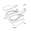
- FIG. 24 is an exploded view of a multi-piece golf club head structure configured to house any of the embodiments disclosed herein.
- FIG. 25 is a rear perspective view of a tenth embodiment of the present invention.
- FIG. 26 is another rear perspective view of the embodiment shown in FIG. 25 .
- FIG. 27 is a sole perspective view of the embodiment shown in FIG. 25 .
- FIG. 28 is a cross-sectional view of the embodiment shown in FIG. 26 along lines 28 - 28 .
- FIG. 29 is a rear perspective view of an eleventh embodiment of the present invention.
- FIG. 30 is an exploded view of the embodiment shown in FIG. 29 .
- FIG. 31 is a cross-sectional view of the embodiment shown in FIG. 29 along lines 31 - 31 .
- FIG. 32 is a cross-sectional view of the face cup shown in FIG. 30 along lines 32 - 32 .
- FIG. 33 is a cross-sectional view of a twelfth embodiment of the present invention.
- FIG. 34 is a cross-sectional view of a thirteenth embodiment of the present invention.
- FIG. 35 is a cross-sectional view of a fourteenth embodiment of the present invention.
- FIG. 36 is a cross-sectional view of a fifteenth embodiment of the present invention.
- FIG. 37 is a cross-sectional view of a sixteenth embodiment of the present invention.
- FIG. 38 is a cross-sectional view of a seventeenth embodiment of the present invention.
- the present invention is generally directed to a golf club head having internal weighting that places the golf club center of gravity (CG) at a point near both the face and the sole of the golf club head.
- the present invention is directed to integrally formed weighting in smaller golf club heads, particularly fairway woods, hybrids, and irons.
- the golf club head 10 which in the first embodiment is a fairway wood head, includes a body 20 having a sole 30 , a crown 40 , a hosel 50 , a cavity 22 , and a weight lip 80 , and a face component 60 comprising a striking face 62 , a return portion 64 , and a cavity 66 .
- the striking face 62 preferably has a high characteristic time (CT).
- CT high characteristic time
- the face component 60 preferably is integrally forged from a metal alloy such as 6-4 titanium or stainless steel, while the body 20 preferably is integrally cast from such alloys.
- the face component 60 and body 20 may be constructed using different methods and with any materials commonly used for golf club manufacturing. In some embodiments, the face component 60 and body 20 may be integrally formed.
- the body 20 may further comprise another weighting element, such as a weight pad, a thickened wall area, or a removable weight screw (not shown) to allow a manufacturer or a golfer to adjust any remaining discretionary weight.
- the weld seam 70 shown in FIG. 3 , has a constant, relatively low thickness, preferably approximately 0.031 inch.
- the weight lip 80 is located inside the cavity 22 and proximate the opening 25 . This construction avoids creating welding problems, but still allows for discretionary mass to be located mostly low and forward in the golf club head.
- the weight lip 80 which preferably is cast into the body 20 but may, in alternative embodiments, be welded or affixed mechanically to the body 20 , extends upwards from the sole 30 and protrudes from the opening 25 of the body 20 .
- the weight lip 80 extends into the cavity 66 of the face component 60 without making contact with the striking face 62 .
- the weight lip 80 preferably comprises at least 20% of the mass of the body 20 , and more preferably 30% of the mass of the body.
- the golf club head 10 may have the weight distribution shown in Table I.
- a groove 82 extends underneath the upper weighted portion 84 of the weight lip 80 , creating an overhang construction which reduces the weight of the weight lip 80 , and thus the overall weight of the golf club head 10 , while still maintaining sufficient weight near the face component 60 to maintain a low, forward CG.
- the weight lip 80 is constructed of multiple materials, with the upper weighted portion 84 composed of a higher density material than the rest of the weight lip 80 .
- the lower support portion 86 of the weight lip 80 is composed of a stainless steel material
- the upper weighted portion 84 is composed of a tungsten alloy and welded or otherwise affixed to the lower support portion 86 of the weight lip 80
- the groove 82 preferably extends slightly further away from the face component 60 and into the lower support portion 86 in order to better counteract the additional weight provided by the higher density upper weighted portion 84 .
- the weight lip 80 includes a larger, squarer upper weighted portion 84 and a narrower lower support portion 86 , with the groove 82 extending inwards away from the face component 60 and upwards towards the crown 40 , such that the groove 82 has a hook-like configuration.
- the upper weighted portion 84 is a separate piece formed of a high density material such as tungsten alloy, which can be welded, glued, or otherwise affixed to the lower support portion 86 . This allows for greater customization of the golf club head 10 during manufacture, as mass properties such as CG and moment of inertia can be tailored to the end user by adjusting the material properties of the weight lip 80 .
- the body 20 of the golf club head 10 includes a weight bar 90 , which is affixed within the interior of the body 20 only at a heel side 24 and toe side 26 of the golf club head 10 , effectively bridging the entire sole 30 .
- This structure allows for activation of the face component 60 and the sole 30 without having an excessive effect on mass properties, as the weight bar 90 acts as a torsion spring during impact of the golf club head 10 with a ball.
- the weight bar 90 is integrally cast with the crown 40 and the heel and toe sides 24 , 26 , and the sole 30 is affixed after the casting is complete, though in alternative embodiments the weight bar 90 may be separately constructed and then affixed within the body 20 at the heel and toe sides 24 , 26 via mechanical fasteners, epoxy, welding, brazing, or any other methods known to a person skilled in the art.
- the weight bar 90 is movably affixed to the heel and toe sides 24 , 26 with a pin 100 or other moving element, and the weight bar 90 has a polygonal shape and is affixed to the pin 100 at one edge 95 , such that rotating the pin 100 anywhere from 1 to 359 degrees moves the majority of the mass of the weight bar 90 to different locations within the body 20 , thus adjusting the location of the golf club head's 10 CG.
- Different weight bar 90 and pin 100 combinations are shown in FIGS. 11A-F , and may include one or more cross-sectional shapes and/or high-density portions or inserts 105 .
- the pin 100 can be temporarily fixed in place by any means known to a person of ordinary skill in the art, including mechanical fasteners and/or removable adhesives, or permanently fixed in place via techniques such as welding, brazing, and/or the use of permanent adhesives.
- the weight bar 90 is affixed to the sole 30 at only two places, one near the heel side 24 of the body 20 and one near the toe side 26 of the body, effectively bridging most of the sole 30 .
- the weight bar 90 may have any cross-sectional shape, including the triangular weight bar 90 structure shown in FIG. 10 , the quadrilateral weight bar 90 structure shown in FIG. 14 , and the trapezoidal weight bar 90 structure shown in FIG. 16 . Portions of the weight bar 90 may be made from different materials to further customize the golf club head 10 and adjust the CG location.
- the face component 60 of the present invention may take different forms and structures to maximize the striking area of the striking face 62 , optimize return in small volume golf clubs like fairway woods, irons, and hybrids, and increase performance characteristics such as characteristic time (CT) and coefficient of resistance (COR).
- the face component 60 may include a return portion 64 that fully or mostly encircles the striking face 62 , forming a face cup, or the return portion 64 may only extend from a portion of the striking face 62 , e.g., from the toe, heel, crown, and/or sole edges 61 , 63 , 65 , 67 of the striking face 62 .
- the face component 60 may include nothing but the striking face 62 , with no return portion 64 .
- the face component 60 has an “r” shaped configuration, with a return portion 64 extending from the crown side of the striking face 62 but nowhere else.
- the weld seam 70 is moved away from the striking face 62 at the crown junction 110 , but remains at the sole, toe, and heel junctions 112 , 114 , 116 of the striking face 62 , which reduces stress at the crown junction while still maintaining high COR and CT values.
- the weld seam 70 also may be non-planar.
- the golf club head 10 may include an additional weight structure.
- the embodiment shown in FIGS. 17-22 includes a weight bar 90 extending from the heel side 24 of the sole 30 to the toe side 26 of the sole 30 , a face component 60 having return portions 64 extending from the crown, sole, and toe edges 65 , 67 , 61 , and an internal weight band 120 extending along most of the junction between the sole 30 and the crown 40 inside the cavity 22 of the golf club head 10 .
- This construction allows the club to have both a desired mass and thin sole 30 and crown 40 portions, thus increasing the compliance of the striking face 62 and optimizing CG.
- the weight bar 90 may be supported with one or more pins 92 , shown in FIGS. 23A and 23B , which are affixed to the sole 30 within the cavity 22 of the golf club head 10 and connect with a bottom surface 94 of the weight bar 90 and/or a rear surface (not shown) of the weight bar 90 .
- the pins preferably are separate pieces composed of a strong, lightweight material such as plastic or composite so that their presence does not detract from the mass configuration created by the weight bar 90 , but in some embodiments may be integrally formed with the sole 30 and the weight bar 90 itself.
- the face component 60 preferably is composed of a high-strength, high performance material to minimize the detrimental influence of weld location on performance.
- the face component 60 preferably is constructed so that the striking face 62 has a maximum CT of 235-260 at its geometric center 68 , and a CT of 205-260 at all points located approximately 0.25 inch from the geometric center, and at least at the high center and low center points on the striking face 62 .
- the golf club head 200 includes a body 220 formed of a material having a lower density than steel, the material being both castable and weldable, the body 220 having a crown opening 222 , a sole opening 224 , and a face opening 226 .
- a sole 230 composed of a steel material, or a denser material than steel, is then welded or brazed to the body 220 , closing off the sole opening 224 .
- a lightweight crown 240 composed of low-density carbon or a thin, strong, lightweight metal is then affixed to the body 220 , closing the crown opening 222 , and a face plate 260 composed of a high strength material is welded or brazed to the body 220 , closing the face opening 226 .
- This multi-material embodiment contributes to optimized center of gravity location, which is particularly useful in fairway woods.
- the face opening 226 and face plate 260 preferably include joint locations that are optimized for minimum interference with the striking surface and flexing regions of the body 220 .
- the golf club head 200 shown in FIG. 24 has a material composition that contributes to optimized moment of inertia values, which is particularly useful in hybrids.
- the body 220 is composed of a material having a higher density than steel, the material being both castable and weldable
- the sole 230 is composed of a steel material or a denser material and is welded or brazed to the body 220
- the crown is 240 is composed of a low-density carbon material and is bonded to the body 220
- the face plate 260 is composed of a high strength material and is welded or brazed to the body.
- the iron-type golf club head 300 comprises a body 305 having a top line 310 , a sole 320 , a toe side 330 , a heel side 340 , and a rear cavity 380 , a face component 350 , and a weight bar 360 .
- the weight bar 360 bridges the sole 320 , forming a narrow slot 370 between the weight bar 360 and the sole 320 and providing room for the face component 350 to deflect downward when the golf club head 300 makes contact with a ball.
- One or more pins 92 examples of which are shown in FIGS.
- the weight bar 360 can be disposed within the slot, between the weight bar 360 and the sole 320 , to provide additional support to the weight bar 360 .
- the weight bar 360 may be rotatable within the rear cavity 380 as disclosed in connection with other embodiments herein, and the golf club head 300 may be made of multiple materials, such as different types of steel.
- the weight bar 360 may be composed of multiple materials in order to affect mass properties of the golf club head 300 , and may have any cross-sectional shape, including the ones disclosed in connection with other embodiments of the present invention.
- the face component 350 is a face insert, but in other embodiments it may be a face plate or a face cup. As shown in FIGS. 25-28 , the face component 350 (and any other face components disclosed herein) preferably has a striking surface with a variable thickness pattern, which may be any pattern disclosed in U.S. Pat. Nos. 7,137,907, 7,101,289, 7,258,626, 7,422,528, 7,448,960, 7,713,140, 8,012,041, and 8,376,876, the disclosure of each of which is hereby incorporated by reference in its entirety herein, and U.S. Patent Publication Number 20120021849, the disclosure of which is also hereby incorporated by reference in its entirety herein.
- the weight lip 80 configurations disclosed herein with respect to wood and hybrid type golf club heads may also be used with iron-type golf club heads, as illustrated by the preferred embodiment shown in FIGS. 29-32 .
- the iron-type golf club head 400 comprises a body 410 and a face cup 420 that are welded together to form a weld seam 430 , which preferably has a constant thickness.
- the body 410 which preferably is integrally cast from a steel material, comprises a top line 411 , a sole 412 , a hosel 413 , a toe end 414 , a heel end 415 , a rear wall 416 , and a front opening 418 that extends completely through the body 410 such that the body 410 has an open back, and also includes a weight lip 440 .
- the weight lip 440 preferably is integrally cast with the body 410 , but may in alternative embodiments be affixed to the body 410 after both pieces are independently created.
- the weight lip 440 of the preferred embodiment extends from the sole 412 and the rear wall 416 of the body 410 towards the front opening 418 , and also extends from the heel end 415 towards the toe end 414 of the body 410 .
- the weight lip 440 may contact both the toe and heel ends 414 , 415 , but in the preferred embodiment, as shown in FIG. 30 , the weight lip 440 only makes contact with the heel end 415 proximate the hosel 413 .
- the face cup 420 comprises a striking face 422 , an upper flange 424 , and a lower flange 426 , which has a length L 1 that is longer than the length L 2 of the upper flange 424 .
- Length L 1 preferably is between 5 and 10 mm, and more preferably is 6 to 9 mm.
- the lower flange 426 preferably has variable thickness, which improves the performance of the golf club head 400 .
- the face cup 420 also comprises a toe-side flange 428 , as shown in FIG. 30 , but no flange along its heel side, where the face cup 420 is welded directly to the heel end 415 of the body 410 proximate the hosel 413 .
- the weight lip 440 protrudes through the front opening 418 , such that when the body 410 is assembled with the face cup 420 , the weight lip 440 extends over the weld seam 430 and approaches, but does not make contact with, the rear surface 423 of the striking face 422 .
- the weight lip 440 in the preferred embodiment has an upper surface 442 that is approximately perpendicular to its forward surface 444 , but in alternative embodiments of the iron-type golf club head 400 of the present invention, shown in FIGS. 33-37 , the weight lip 440 may have different dimensions and structures. In the embodiments shown in FIGS.
- the open back of the body 410 is closed with a back cap 450 to create a hollow iron-type golf club head 400 .
- the back cap 450 may be composed of the same material as the body 410 and/or the face cup 420 , or may be composed of a lightweight material such as plastic or composite.
- a separate, lightweight material 460 such as plastic, composite, or rubber is added to the forward surface 444 of the weight lip 440 to connect the weight lip 440 to the striking face 422 (or any other part of the face cup 420 ).
- the lightweight material 460 preferably is disposed approximately 0.075 inch vertically from the lower flange 426 , and is spaced at least 0.5 inches from the center of the rear surface 423 of the striking face 422 .
- the inertia of the weight lip 80 , 440 or weight bar 90 , 360 during impact of the golf club head 10 with a ball improves sole 30 compliance by enhancing the bending capabilities of thinner regions of the sole 30 .
- the weight construction shown in these Figures also allows the face component 60 to have a face cup (a return portion 64 extending part or completely around the periphery of the striking face 62 ) construction without sacrificing an optimized center of gravity location, and also allows the manufacturer of the club head 10 to take weight away from, and thus thin out, the sole 30 , which allows the sole 30 to flex and bend more easily and thus contribute more to performance of the face component 60 .
Landscapes
- Health & Medical Sciences (AREA)
- General Health & Medical Sciences (AREA)
- Physical Education & Sports Medicine (AREA)
- Life Sciences & Earth Sciences (AREA)
- Biophysics (AREA)
- Golf Clubs (AREA)
Abstract
Description
| TABLE I | |||
| Club Part | Weight (in grams) | ||
| |
167 | ||
| |
49 | ||
| |
38 | ||
| Total |
205 | ||
Claims (18)
Priority Applications (21)
| Application Number | Priority Date | Filing Date | Title |
|---|---|---|---|
| US14/285,479 US9211451B1 (en) | 2012-04-19 | 2014-05-22 | Weighted golf club head |
| US14/797,512 US9586105B1 (en) | 2012-04-19 | 2015-07-13 | Weighted golf club head |
| US14/847,227 US9486677B1 (en) | 2013-03-07 | 2015-09-08 | Weighted golf club head having composite tubes |
| US15/279,188 US9687701B1 (en) | 2012-06-27 | 2016-09-28 | Weighted golf club head having stress-relieving tubes |
| US15/285,712 US9782642B1 (en) | 2012-04-19 | 2016-10-05 | Golf club head with elevated internal weight |
| US15/446,754 US9694257B1 (en) | 2012-06-27 | 2017-03-01 | Golf club head with structural columns |
| US15/447,638 US9687702B1 (en) | 2012-06-27 | 2017-03-02 | Golf club head with structural columns |
| US15/452,516 US9908016B2 (en) | 2012-06-27 | 2017-03-07 | Golf club head having optimized ball speed to CT relationship |
| US15/622,267 US9931549B1 (en) | 2012-06-27 | 2017-06-14 | Weighted golf club head having stress-relieving tubes |
| US15/627,217 US9827469B1 (en) | 2012-06-27 | 2017-06-19 | Iron-type golf club head with elevated weight bar and stress-relieving structures |
| US15/628,100 US9855476B2 (en) | 2012-06-27 | 2017-06-20 | Golf club head with structural columns |
| US15/628,364 US9987527B1 (en) | 2012-06-27 | 2017-06-20 | Iron-type golf club head with stiffening rods |
| US15/628,514 US9908017B2 (en) | 2012-06-27 | 2017-06-20 | Golf club head with structural columns |
| US15/637,902 US9981167B2 (en) | 2012-06-27 | 2017-06-29 | Golf club head with structural columns |
| US15/717,635 US10201733B2 (en) | 2012-06-27 | 2017-09-27 | Golf club head with structural columns |
| US15/724,468 US10080932B2 (en) | 2012-04-19 | 2017-10-04 | Golf club head with elevated internal weight |
| US15/817,158 US10010771B2 (en) | 2012-06-27 | 2017-11-17 | Iron-type golf club head with elevated weight bar and stress-relieving structures |
| US15/866,986 US10213662B2 (en) | 2012-06-27 | 2018-01-10 | Golf club head having stiffening members and variable face thickness |
| US15/869,591 US10406408B1 (en) | 2012-06-27 | 2018-01-12 | Golf club head having stiffening members and variable face thickness |
| US16/139,978 US10245477B2 (en) | 2012-04-19 | 2018-09-24 | Golf club head with elevated internal weight |
| US16/371,334 US10406407B2 (en) | 2012-04-19 | 2019-04-01 | Golf club head with elevated internal weight |
Applications Claiming Priority (8)
| Application Number | Priority Date | Filing Date | Title |
|---|---|---|---|
| US201261635363P | 2012-04-19 | 2012-04-19 | |
| US13/475,497 US8257195B1 (en) | 2012-04-19 | 2012-05-18 | Weighted golf club head |
| US13/559,279 US8328661B1 (en) | 2012-04-19 | 2012-07-26 | Weighted golf club head |
| US13/667,692 US8414420B1 (en) | 2012-04-19 | 2012-11-02 | Weighted golf club head |
| US13/751,447 US8425346B1 (en) | 2012-04-19 | 2013-01-28 | Weighted golf club head |
| US13/788,173 US8926448B1 (en) | 2012-04-19 | 2013-03-07 | Weighted golf club head |
| US13/797,507 US8900070B1 (en) | 2013-03-07 | 2013-03-12 | Weighted golf club head |
| US14/285,479 US9211451B1 (en) | 2012-04-19 | 2014-05-22 | Weighted golf club head |
Related Parent Applications (3)
| Application Number | Title | Priority Date | Filing Date |
|---|---|---|---|
| US13/788,173 Continuation-In-Part US8926448B1 (en) | 2012-04-19 | 2013-03-07 | Weighted golf club head |
| US13/797,507 Continuation-In-Part US8900070B1 (en) | 2012-04-19 | 2013-03-12 | Weighted golf club head |
| US14/847,227 Continuation-In-Part US9486677B1 (en) | 2012-06-27 | 2015-09-08 | Weighted golf club head having composite tubes |
Related Child Applications (2)
| Application Number | Title | Priority Date | Filing Date |
|---|---|---|---|
| US14/797,512 Continuation-In-Part US9586105B1 (en) | 2012-04-19 | 2015-07-13 | Weighted golf club head |
| US14/847,227 Continuation-In-Part US9486677B1 (en) | 2012-06-27 | 2015-09-08 | Weighted golf club head having composite tubes |
Publications (1)
| Publication Number | Publication Date |
|---|---|
| US9211451B1 true US9211451B1 (en) | 2015-12-15 |
Family
ID=54783035
Family Applications (1)
| Application Number | Title | Priority Date | Filing Date |
|---|---|---|---|
| US14/285,479 Active 2032-06-10 US9211451B1 (en) | 2012-04-19 | 2014-05-22 | Weighted golf club head |
Country Status (1)
| Country | Link |
|---|---|
| US (1) | US9211451B1 (en) |
Cited By (29)
| Publication number | Priority date | Publication date | Assignee | Title |
|---|---|---|---|---|
| US9586105B1 (en) * | 2012-04-19 | 2017-03-07 | Callaway Golf Company | Weighted golf club head |
| US9597561B1 (en) * | 2015-06-30 | 2017-03-21 | Callaway Golf Company | Golf club head having face stress-reduction features |
| US20170173417A1 (en) * | 2012-06-27 | 2017-06-22 | Callaway Golf Company | Golf Club Head With Structural Columns |
| US9687701B1 (en) * | 2012-06-27 | 2017-06-27 | Callaway Golf Company | Weighted golf club head having stress-relieving tubes |
| US20170182381A1 (en) * | 2012-06-27 | 2017-06-29 | Callaway Golf Company | Golf Club Head With Structural Columns |
| US9782642B1 (en) * | 2012-04-19 | 2017-10-10 | Callaway Golf Company | Golf club head with elevated internal weight |
| CN107551505A (en) * | 2016-06-30 | 2018-01-09 | 邓禄普体育用品株式会社 | Iron golf club head |
| US20180071594A1 (en) * | 2012-06-27 | 2018-03-15 | Callaway Golf Company | Iron-Type Golf Club Head With Elevated Weight Bar and Stress-Relieving Structures |
| US10112084B2 (en) | 2016-03-25 | 2018-10-30 | Karsten Manufacturing Corporation | Golf club head having a support to limit faceplate deformation |
| US10610747B2 (en) | 2004-11-08 | 2020-04-07 | Taylor Made Golf Company, Inc. | Golf club |
| US20200206586A1 (en) * | 2018-12-27 | 2020-07-02 | Sumitomo Rubber Industries, Ltd. | Golf club head |
| US20200206585A1 (en) * | 2012-06-08 | 2020-07-02 | Taylor Made Golf Company, Inc. | Iron type golf club head |
| US10881926B1 (en) * | 2019-07-29 | 2021-01-05 | Taylor Made Golf Company, Inc. | Iron golf club head |
| US11033782B1 (en) | 2020-03-04 | 2021-06-15 | Cobra Golf Incorporated | Systems and methods for a weighted golf club head |
| US11065511B2 (en) * | 2019-09-20 | 2021-07-20 | Sumitomo Rubber Industries, Ltd. | Golf club head and manufacturing method thereof |
| US20210331045A1 (en) * | 2019-05-10 | 2021-10-28 | Taylor Made Golf Company, Inc. | Golf club |
| US11207577B1 (en) | 2020-03-04 | 2021-12-28 | Cobra Golf Incorporated | Systems and methods for a weighted golf club head |
| US11213727B2 (en) * | 2019-11-07 | 2022-01-04 | Sumitomo Rubber Industries, Ltd. | Golf club head |
| US11351429B2 (en) * | 2019-05-10 | 2022-06-07 | Taylor Made Golf Company, Inc. | Golf club |
| US20220184475A1 (en) * | 2011-11-28 | 2022-06-16 | Acushnet Company | Co-forged golf club head and method of manufacture |
| US20220233924A1 (en) * | 2021-01-22 | 2022-07-28 | Karsten Manufacturing Corporation | Golf club head with l-shaped faceplate and dynamic lofting features |
| US11400351B2 (en) * | 2019-05-10 | 2022-08-02 | Taylor Made Golf Company, Inc. | Golf club |
| US11413510B2 (en) * | 2019-05-10 | 2022-08-16 | Taylor Made Golf Company, Inc. | Golf club |
| US11420097B2 (en) * | 2016-12-29 | 2022-08-23 | Taylor Made Golf Company, Inc. | Golf club head |
| US11458373B2 (en) * | 2020-04-21 | 2022-10-04 | Karsten Manufacturing Corporation | Golf club heads with internal undercuts |
| US11618213B1 (en) | 2020-04-17 | 2023-04-04 | Cobra Golf Incorporated | Systems and methods for additive manufacturing of a golf club |
| US11618079B1 (en) | 2020-04-17 | 2023-04-04 | Cobra Golf Incorporated | Systems and methods for additive manufacturing of a golf club |
| US20240017143A1 (en) * | 2022-07-14 | 2024-01-18 | Acushnet Company | Internally damped golf club head |
| US11931630B2 (en) * | 2021-09-06 | 2024-03-19 | Sumitomo Rubber Industries, Ltd. | Golf club head |
Citations (30)
| Publication number | Priority date | Publication date | Assignee | Title |
|---|---|---|---|---|
| US4826172A (en) * | 1987-03-12 | 1989-05-02 | Antonious A J | Golf club head |
| US5014993A (en) * | 1990-04-24 | 1991-05-14 | Antonious A J | Iron type golf club head |
| US6030293A (en) * | 1997-11-20 | 2000-02-29 | Kabushiki Kaisha Endo Seisakusho | Golf club |
| US6045456A (en) * | 1997-01-23 | 2000-04-04 | Cobra Golf Incorporated | Golf club with improved weighting and vibration dampening |
| US6077173A (en) * | 1997-12-12 | 2000-06-20 | Tom Stites & Associates, Inc. | Iron-type golf club head |
| US6309311B1 (en) * | 2000-01-28 | 2001-10-30 | Clive S. Lu | Golf club head with weighted force absorbing attachment |
| US6506129B2 (en) * | 2001-02-21 | 2003-01-14 | Archer C. C. Chen | Golf club head capable of enlarging flexible area of ball-hitting face thereof |
| US6688989B2 (en) * | 2002-04-25 | 2004-02-10 | Acushnet Company | Iron club with captive third piece |
| US6921344B2 (en) | 2003-08-13 | 2005-07-26 | Acushnet Company | Reinforced golf club head having sandwich construction |
| US6991559B2 (en) * | 2002-06-07 | 2006-01-31 | Sri Sports Limited | Golf club head |
| US7025695B2 (en) * | 2003-04-03 | 2006-04-11 | Sri Sports Limited | Golf club head |
| US7083531B2 (en) * | 2004-07-29 | 2006-08-01 | Callaway Golf Company | Iron-type golf club |
| US7101289B2 (en) * | 2004-10-07 | 2006-09-05 | Callaway Golf Company | Golf club head with variable face thickness |
| US7118493B2 (en) * | 1999-11-01 | 2006-10-10 | Callaway Golf Company | Multiple material golf club head |
| US7207899B2 (en) | 2002-08-30 | 2007-04-24 | Bridgestone Sports Co., Ltd. | Golf club head |
| US7476162B2 (en) * | 2003-09-19 | 2009-01-13 | Nike, Inc. | Golf club head having a bridge member and a damping element |
| US7662051B2 (en) * | 2007-09-11 | 2010-02-16 | Cindy Rhodes | Golf head |
| US7662050B2 (en) | 2005-04-14 | 2010-02-16 | Acushnet Company | Iron-type golf clubs |
| US7744486B2 (en) | 2008-01-28 | 2010-06-29 | Nelson Precision Casting Co., Ltd. | Golf club head |
| US7789771B2 (en) * | 2008-02-15 | 2010-09-07 | Sri Sports Limited | Golf club head |
| US7798913B2 (en) * | 2008-07-31 | 2010-09-21 | Karsten Manufacturing Corporation | Golf clubs with variable moment of inertia and methods of manufacture thereof |
| US7815523B2 (en) | 2004-08-11 | 2010-10-19 | Acushnet Company | Variable density golf club |
| US7871338B2 (en) * | 2007-11-26 | 2011-01-18 | Sri Sports Limited | Golf club head |
| US7988568B2 (en) * | 2008-01-17 | 2011-08-02 | Nike, Inc. | Golf clubs and golf club heads with adjustable center of gravity and moment of inertia characteristics |
| US8088025B2 (en) | 2009-07-29 | 2012-01-03 | Taylor Made Golf Company, Inc. | Golf club head |
| US8257195B1 (en) * | 2012-04-19 | 2012-09-04 | Callaway Golf Company | Weighted golf club head |
| US20130150177A1 (en) | 2011-12-07 | 2013-06-13 | Bridgestone Sports Co., Ltd | Golf club head |
| US8475293B2 (en) * | 2010-09-13 | 2013-07-02 | Acushnet Company | Iron golf club head with improved performance |
| US8900070B1 (en) * | 2013-03-07 | 2014-12-02 | Callaway Golf Company | Weighted golf club head |
| US8926448B1 (en) * | 2012-04-19 | 2015-01-06 | Callaway Golf Company | Weighted golf club head |
-
2014
- 2014-05-22 US US14/285,479 patent/US9211451B1/en active Active
Patent Citations (35)
| Publication number | Priority date | Publication date | Assignee | Title |
|---|---|---|---|---|
| US4826172A (en) * | 1987-03-12 | 1989-05-02 | Antonious A J | Golf club head |
| US5014993A (en) * | 1990-04-24 | 1991-05-14 | Antonious A J | Iron type golf club head |
| US6045456A (en) * | 1997-01-23 | 2000-04-04 | Cobra Golf Incorporated | Golf club with improved weighting and vibration dampening |
| US6030293A (en) * | 1997-11-20 | 2000-02-29 | Kabushiki Kaisha Endo Seisakusho | Golf club |
| US6077173A (en) * | 1997-12-12 | 2000-06-20 | Tom Stites & Associates, Inc. | Iron-type golf club head |
| US7118493B2 (en) * | 1999-11-01 | 2006-10-10 | Callaway Golf Company | Multiple material golf club head |
| US6309311B1 (en) * | 2000-01-28 | 2001-10-30 | Clive S. Lu | Golf club head with weighted force absorbing attachment |
| US6506129B2 (en) * | 2001-02-21 | 2003-01-14 | Archer C. C. Chen | Golf club head capable of enlarging flexible area of ball-hitting face thereof |
| US6688989B2 (en) * | 2002-04-25 | 2004-02-10 | Acushnet Company | Iron club with captive third piece |
| US6991559B2 (en) * | 2002-06-07 | 2006-01-31 | Sri Sports Limited | Golf club head |
| US7207899B2 (en) | 2002-08-30 | 2007-04-24 | Bridgestone Sports Co., Ltd. | Golf club head |
| US7025695B2 (en) * | 2003-04-03 | 2006-04-11 | Sri Sports Limited | Golf club head |
| US6921344B2 (en) | 2003-08-13 | 2005-07-26 | Acushnet Company | Reinforced golf club head having sandwich construction |
| US7476162B2 (en) * | 2003-09-19 | 2009-01-13 | Nike, Inc. | Golf club head having a bridge member and a damping element |
| US7083531B2 (en) * | 2004-07-29 | 2006-08-01 | Callaway Golf Company | Iron-type golf club |
| US7815523B2 (en) | 2004-08-11 | 2010-10-19 | Acushnet Company | Variable density golf club |
| US7101289B2 (en) * | 2004-10-07 | 2006-09-05 | Callaway Golf Company | Golf club head with variable face thickness |
| US7662050B2 (en) | 2005-04-14 | 2010-02-16 | Acushnet Company | Iron-type golf clubs |
| US7662051B2 (en) * | 2007-09-11 | 2010-02-16 | Cindy Rhodes | Golf head |
| US7871338B2 (en) * | 2007-11-26 | 2011-01-18 | Sri Sports Limited | Golf club head |
| US7988568B2 (en) * | 2008-01-17 | 2011-08-02 | Nike, Inc. | Golf clubs and golf club heads with adjustable center of gravity and moment of inertia characteristics |
| US7744486B2 (en) | 2008-01-28 | 2010-06-29 | Nelson Precision Casting Co., Ltd. | Golf club head |
| US7789771B2 (en) * | 2008-02-15 | 2010-09-07 | Sri Sports Limited | Golf club head |
| US7798913B2 (en) * | 2008-07-31 | 2010-09-21 | Karsten Manufacturing Corporation | Golf clubs with variable moment of inertia and methods of manufacture thereof |
| US8517863B2 (en) | 2009-07-29 | 2013-08-27 | Taylor Made Golf Company, Inc. | Golf club head |
| US8088025B2 (en) | 2009-07-29 | 2012-01-03 | Taylor Made Golf Company, Inc. | Golf club head |
| US8814725B2 (en) | 2009-07-29 | 2014-08-26 | Taylor Made Golf Company, Inc. | Golf club head |
| US8475293B2 (en) * | 2010-09-13 | 2013-07-02 | Acushnet Company | Iron golf club head with improved performance |
| US20130150177A1 (en) | 2011-12-07 | 2013-06-13 | Bridgestone Sports Co., Ltd | Golf club head |
| US8257195B1 (en) * | 2012-04-19 | 2012-09-04 | Callaway Golf Company | Weighted golf club head |
| US8328661B1 (en) * | 2012-04-19 | 2012-12-11 | Callaway Golf Company | Weighted golf club head |
| US8414420B1 (en) * | 2012-04-19 | 2013-04-09 | Callaway Golf Company | Weighted golf club head |
| US8425346B1 (en) * | 2012-04-19 | 2013-04-23 | Callaway Golf Company | Weighted golf club head |
| US8926448B1 (en) * | 2012-04-19 | 2015-01-06 | Callaway Golf Company | Weighted golf club head |
| US8900070B1 (en) * | 2013-03-07 | 2014-12-02 | Callaway Golf Company | Weighted golf club head |
Cited By (64)
| Publication number | Priority date | Publication date | Assignee | Title |
|---|---|---|---|---|
| US10610747B2 (en) | 2004-11-08 | 2020-04-07 | Taylor Made Golf Company, Inc. | Golf club |
| US11918867B2 (en) * | 2011-11-28 | 2024-03-05 | Acushnet Company | Co-forged golf club head and method of manufacture |
| US20220184475A1 (en) * | 2011-11-28 | 2022-06-16 | Acushnet Company | Co-forged golf club head and method of manufacture |
| US20180021637A1 (en) * | 2012-04-19 | 2018-01-25 | Callaway Golf Company | Golf Club Head With Elevated Internal Weight |
| US9586105B1 (en) * | 2012-04-19 | 2017-03-07 | Callaway Golf Company | Weighted golf club head |
| US10406407B2 (en) * | 2012-04-19 | 2019-09-10 | Callaway Golf Company | Golf club head with elevated internal weight |
| US20190224535A1 (en) * | 2012-04-19 | 2019-07-25 | Callaway Golf Company | Golf Club Head With Elevated Internal Weight |
| US10245477B2 (en) * | 2012-04-19 | 2019-04-02 | Callaway Golf Company | Golf club head with elevated internal weight |
| US9782642B1 (en) * | 2012-04-19 | 2017-10-10 | Callaway Golf Company | Golf club head with elevated internal weight |
| US10080932B2 (en) * | 2012-04-19 | 2018-09-25 | Callaway Golf Company | Golf club head with elevated internal weight |
| US10870042B2 (en) * | 2012-06-08 | 2020-12-22 | Taylor Made Golf Company, Inc. | Iron type golf club head |
| US20200206585A1 (en) * | 2012-06-08 | 2020-07-02 | Taylor Made Golf Company, Inc. | Iron type golf club head |
| US9931549B1 (en) * | 2012-06-27 | 2018-04-03 | Callaway Golf Company | Weighted golf club head having stress-relieving tubes |
| US9694257B1 (en) * | 2012-06-27 | 2017-07-04 | Callaway Golf Company | Golf club head with structural columns |
| US9908017B2 (en) * | 2012-06-27 | 2018-03-06 | Callaway Golf Company | Golf club head with structural columns |
| US20180071594A1 (en) * | 2012-06-27 | 2018-03-15 | Callaway Golf Company | Iron-Type Golf Club Head With Elevated Weight Bar and Stress-Relieving Structures |
| US9855476B2 (en) * | 2012-06-27 | 2018-01-02 | Callaway Golf Company | Golf club head with structural columns |
| US9981167B2 (en) * | 2012-06-27 | 2018-05-29 | Callaway Golf Company | Golf club head with structural columns |
| US10010771B2 (en) * | 2012-06-27 | 2018-07-03 | Callaway Golf Company | Iron-type golf club head with elevated weight bar and stress-relieving structures |
| US20170296884A1 (en) * | 2012-06-27 | 2017-10-19 | Callaway Golf Company | Golf Club Head With Structural Columns |
| US20170173417A1 (en) * | 2012-06-27 | 2017-06-22 | Callaway Golf Company | Golf Club Head With Structural Columns |
| US20170282022A1 (en) * | 2012-06-27 | 2017-10-05 | Callaway Golf Company | Golf Club Head With Structural Columns |
| US20170282023A1 (en) * | 2012-06-27 | 2017-10-05 | Callaway Golf Company | Golf Club Head With Structural Columns |
| US9687701B1 (en) * | 2012-06-27 | 2017-06-27 | Callaway Golf Company | Weighted golf club head having stress-relieving tubes |
| US9687702B1 (en) * | 2012-06-27 | 2017-06-27 | Callaway Golf Company | Golf club head with structural columns |
| US20170182381A1 (en) * | 2012-06-27 | 2017-06-29 | Callaway Golf Company | Golf Club Head With Structural Columns |
| US11426639B2 (en) | 2013-12-31 | 2022-08-30 | Taylor Made Golf Company, Inc. | Golf club |
| US9597561B1 (en) * | 2015-06-30 | 2017-03-21 | Callaway Golf Company | Golf club head having face stress-reduction features |
| US10478683B2 (en) | 2016-03-25 | 2019-11-19 | Karsten Manufacturing Corporation | Golf club head having a support to limit faceplate deformation |
| US10112084B2 (en) | 2016-03-25 | 2018-10-30 | Karsten Manufacturing Corporation | Golf club head having a support to limit faceplate deformation |
| US10967233B2 (en) | 2016-03-25 | 2021-04-06 | Karsten Manufacturing Corporation | Golf club head having a support to limit faceplate deformation |
| US11534664B2 (en) | 2016-03-25 | 2022-12-27 | Karsten Manufacturing Corporation | Golf club head having a support to limit faceplate deformation |
| CN107551505A (en) * | 2016-06-30 | 2018-01-09 | 邓禄普体育用品株式会社 | Iron golf club head |
| US20230001271A1 (en) * | 2016-12-29 | 2023-01-05 | Taylor Made Golf Company, Inc. | Golf club head |
| US11420097B2 (en) * | 2016-12-29 | 2022-08-23 | Taylor Made Golf Company, Inc. | Golf club head |
| US11938383B2 (en) * | 2016-12-29 | 2024-03-26 | Taylor Made Golf Company, Inc. | Golf club head |
| US20200206586A1 (en) * | 2018-12-27 | 2020-07-02 | Sumitomo Rubber Industries, Ltd. | Golf club head |
| US11235208B2 (en) * | 2018-12-27 | 2022-02-01 | Sumitomo Rubber Industries, Ltd. | Golf club head |
| US20210331045A1 (en) * | 2019-05-10 | 2021-10-28 | Taylor Made Golf Company, Inc. | Golf club |
| US11458374B2 (en) * | 2019-05-10 | 2022-10-04 | Taylor Made Golf Company, Inc. | Golf club |
| US11400351B2 (en) * | 2019-05-10 | 2022-08-02 | Taylor Made Golf Company, Inc. | Golf club |
| US11413510B2 (en) * | 2019-05-10 | 2022-08-16 | Taylor Made Golf Company, Inc. | Golf club |
| US20230052836A1 (en) * | 2019-05-10 | 2023-02-16 | Taylor Made Golf Company, Inc. | Golf club |
| US11883724B2 (en) | 2019-05-10 | 2024-01-30 | Taylor Made Golf Company, Inc. | Golf club |
| US11351429B2 (en) * | 2019-05-10 | 2022-06-07 | Taylor Made Golf Company, Inc. | Golf club |
| US11951365B2 (en) * | 2019-05-10 | 2024-04-09 | Taylor Made Golf Company, Inc. | Golf club |
| US20230028968A1 (en) * | 2019-05-10 | 2023-01-26 | Taylor Made Golf Company, Inc. | Golf club |
| US11918874B2 (en) | 2019-05-10 | 2024-03-05 | Taylor Made Golf Company, Inc. | Golf club |
| US10881926B1 (en) * | 2019-07-29 | 2021-01-05 | Taylor Made Golf Company, Inc. | Iron golf club head |
| US11497972B2 (en) | 2019-07-29 | 2022-11-15 | Taylor Made Golf Company, Inc. | Iron golf club head |
| US11065511B2 (en) * | 2019-09-20 | 2021-07-20 | Sumitomo Rubber Industries, Ltd. | Golf club head and manufacturing method thereof |
| US11213727B2 (en) * | 2019-11-07 | 2022-01-04 | Sumitomo Rubber Industries, Ltd. | Golf club head |
| US11541283B1 (en) | 2020-03-04 | 2023-01-03 | Cobra Golf Incorporated | Systems and methods for a weighted golf club head |
| US11679310B1 (en) | 2020-03-04 | 2023-06-20 | Cobra Golf Incorporated | Systems and methods for a weighted golf club head |
| US11207577B1 (en) | 2020-03-04 | 2021-12-28 | Cobra Golf Incorporated | Systems and methods for a weighted golf club head |
| US11033782B1 (en) | 2020-03-04 | 2021-06-15 | Cobra Golf Incorporated | Systems and methods for a weighted golf club head |
| US11618213B1 (en) | 2020-04-17 | 2023-04-04 | Cobra Golf Incorporated | Systems and methods for additive manufacturing of a golf club |
| US11618079B1 (en) | 2020-04-17 | 2023-04-04 | Cobra Golf Incorporated | Systems and methods for additive manufacturing of a golf club |
| US20230023428A1 (en) * | 2020-04-21 | 2023-01-26 | Karsten Manufacturing Corporation | Golf club heads with internal undercuts |
| US11458373B2 (en) * | 2020-04-21 | 2022-10-04 | Karsten Manufacturing Corporation | Golf club heads with internal undercuts |
| US11944879B2 (en) * | 2021-01-22 | 2024-04-02 | Karsten Manufacturing Corporation | Golf club head with L-shaped faceplate and dynamic lofting features |
| US20220233924A1 (en) * | 2021-01-22 | 2022-07-28 | Karsten Manufacturing Corporation | Golf club head with l-shaped faceplate and dynamic lofting features |
| US11931630B2 (en) * | 2021-09-06 | 2024-03-19 | Sumitomo Rubber Industries, Ltd. | Golf club head |
| US20240017143A1 (en) * | 2022-07-14 | 2024-01-18 | Acushnet Company | Internally damped golf club head |
Similar Documents
| Publication | Publication Date | Title |
|---|---|---|
| US9211451B1 (en) | Weighted golf club head | |
| US8900070B1 (en) | Weighted golf club head | |
| US8926448B1 (en) | Weighted golf club head | |
| US8425346B1 (en) | Weighted golf club head | |
| US10441856B2 (en) | Golf club head | |
| US9649541B2 (en) | Golf club with multi-component construction | |
| US10245477B2 (en) | Golf club head with elevated internal weight | |
| US7753807B2 (en) | Golf club head | |
| US9174102B2 (en) | Putter head with distributive frame and weights | |
| US8870681B2 (en) | Golf club head and golf club | |
| US9586105B1 (en) | Weighted golf club head | |
| JP2007229002A (en) | Golf club head | |
| KR20140049479A (en) | Golf club head | |
| US8876631B2 (en) | Golf club iron with high density leading edge | |
| JP2017189700A (en) | Weighted golf club head | |
| US7473191B2 (en) | Golf club head | |
| JP6188759B2 (en) | Golf club head with weight | |
| US20170304689A1 (en) | Golf club head | |
| JP2004135730A (en) | Long golf club | |
| US20220111264A1 (en) | Golf club head | |
| WO2022056215A1 (en) | Fairway wood golf club head with low cg |
Legal Events
| Date | Code | Title | Description |
|---|---|---|---|
| AS | Assignment |
Owner name: CALLAWAY GOLF COMPANY, CALIFORNIA Free format text: ASSIGNMENT OF ASSIGNORS INTEREST;ASSIGNORS:WESTRUM, JOSHUA D.;ROCHE, BROOKS;WIELAND, CHRIS J.;AND OTHERS;SIGNING DATES FROM 20140520 TO 20140623;REEL/FRAME:033164/0901 |
|
| STCF | Information on status: patent grant |
Free format text: PATENTED CASE |
|
| AS | Assignment |
Owner name: BANK OF AMERICA, N.A., CALIFORNIA Free format text: SECURITY INTEREST;ASSIGNORS:CALLAWAY GOLF COMPANY;CALLAWAY GOLF SALES COMPANY;CALLAWAY GOLF BALL OPERATIONS, INC.;AND OTHERS;REEL/FRAME:045350/0741 Effective date: 20171120 |
|
| AS | Assignment |
Owner name: BANK OF AMERICA, N.A., AS ADMINISTRATIVE AGENT, NO Free format text: SECURITY AGREEMENT;ASSIGNORS:CALLAWAY GOLF COMPANY;OGIO INTERNATIONAL, INC.;REEL/FRAME:048172/0001 Effective date: 20190104 Owner name: BANK OF AMERICA, N.A., AS ADMINISTRATIVE AGENT, NORTH CAROLINA Free format text: SECURITY AGREEMENT;ASSIGNORS:CALLAWAY GOLF COMPANY;OGIO INTERNATIONAL, INC.;REEL/FRAME:048172/0001 Effective date: 20190104 |
|
| AS | Assignment |
Owner name: BANK OF AMERICA, N.A., CALIFORNIA Free format text: SECURITY INTEREST;ASSIGNORS:CALLAWAY GOLF COMPANY;CALLAWAY GOLF SALES COMPANY;CALLAWAY GOLF BALL OPERATIONS, INC.;AND OTHERS;REEL/FRAME:048110/0352 Effective date: 20190104 |
|
| MAFP | Maintenance fee payment |
Free format text: PAYMENT OF MAINTENANCE FEE, 4TH YEAR, LARGE ENTITY (ORIGINAL EVENT CODE: M1551); ENTITY STATUS OF PATENT OWNER: LARGE ENTITY Year of fee payment: 4 |
|
| AS | Assignment |
Owner name: OGIO INTERNATIONAL, INC., CALIFORNIA Free format text: RELEASE (REEL 048172 / FRAME 0001);ASSIGNOR:BANK OF AMERICA, N.A.;REEL/FRAME:063622/0187 Effective date: 20230316 Owner name: TOPGOLF CALLAWAY BRANDS CORP. (F/K/A CALLAWAY GOLF COMPANY), CALIFORNIA Free format text: RELEASE (REEL 048172 / FRAME 0001);ASSIGNOR:BANK OF AMERICA, N.A.;REEL/FRAME:063622/0187 Effective date: 20230316 |
|
| AS | Assignment |
Owner name: BANK OF AMERICA, N.A, AS COLLATERAL AGENT, NORTH CAROLINA Free format text: SECURITY AGREEMENT;ASSIGNORS:TOPGOLF CALLAWAY BRANDS CORP. (FORMERLY CALLAWAY GOLF COMPANY);OGIO INTERNATIONAL, INC.;TOPGOLF INTERNATIONAL, INC.;AND OTHERS;REEL/FRAME:063665/0176 Effective date: 20230512 |
|
| AS | Assignment |
Owner name: BANK OF AMERICA, N.A., CALIFORNIA Free format text: SECURITY INTEREST;ASSIGNORS:TOPGOLF CALLAWAY BRANDS CORP.;OGIO INTERNATIONAL, INC.;TOPGOLF INTERNATIONAL, INC.;AND OTHERS;REEL/FRAME:063692/0009 Effective date: 20230517 |
|
| MAFP | Maintenance fee payment |
Free format text: PAYMENT OF MAINTENANCE FEE, 8TH YEAR, LARGE ENTITY (ORIGINAL EVENT CODE: M1552); ENTITY STATUS OF PATENT OWNER: LARGE ENTITY Year of fee payment: 8 |