US9215092B2 - Clock selection for synchronous Ethernet - Google Patents
Clock selection for synchronous Ethernet Download PDFInfo
- Publication number
- US9215092B2 US9215092B2 US13/158,277 US201113158277A US9215092B2 US 9215092 B2 US9215092 B2 US 9215092B2 US 201113158277 A US201113158277 A US 201113158277A US 9215092 B2 US9215092 B2 US 9215092B2
- Authority
- US
- United States
- Prior art keywords
- ethernet phy
- phy
- timing
- ethernet
- indication
- Prior art date
- Legal status (The legal status is an assumption and is not a legal conclusion. Google has not performed a legal analysis and makes no representation as to the accuracy of the status listed.)
- Active, expires
Links
Images


Classifications
-
- H—ELECTRICITY
- H04—ELECTRIC COMMUNICATION TECHNIQUE
- H04L—TRANSMISSION OF DIGITAL INFORMATION, e.g. TELEGRAPHIC COMMUNICATION
- H04L12/00—Data switching networks
- H04L12/28—Data switching networks characterised by path configuration, e.g. LAN [Local Area Networks] or WAN [Wide Area Networks]
- H04L12/46—Interconnection of networks
- H04L12/4604—LAN interconnection over a backbone network, e.g. Internet, Frame Relay
- H04L12/462—LAN interconnection over a bridge based backbone
- H04L12/4625—Single bridge functionality, e.g. connection of two networks over a single bridge
-
- H—ELECTRICITY
- H04—ELECTRIC COMMUNICATION TECHNIQUE
- H04J—MULTIPLEX COMMUNICATION
- H04J3/00—Time-division multiplex systems
- H04J3/02—Details
- H04J3/06—Synchronising arrangements
- H04J3/0635—Clock or time synchronisation in a network
- H04J3/0638—Clock or time synchronisation among nodes; Internode synchronisation
- H04J3/0641—Change of the master or reference, e.g. take-over or failure of the master
-
- H—ELECTRICITY
- H04—ELECTRIC COMMUNICATION TECHNIQUE
- H04J—MULTIPLEX COMMUNICATION
- H04J3/00—Time-division multiplex systems
- H04J3/02—Details
- H04J3/06—Synchronising arrangements
- H04J3/0635—Clock or time synchronisation in a network
- H04J3/0685—Clock or time synchronisation in a node; Intranode synchronisation
- H04J3/0688—Change of the master or reference, e.g. take-over or failure of the master
-
- H—ELECTRICITY
- H04—ELECTRIC COMMUNICATION TECHNIQUE
- H04J—MULTIPLEX COMMUNICATION
- H04J3/00—Time-division multiplex systems
- H04J3/02—Details
- H04J3/06—Synchronising arrangements
- H04J3/0635—Clock or time synchronisation in a network
- H04J3/0638—Clock or time synchronisation among nodes; Internode synchronisation
- H04J3/0644—External master-clock
-
- H—ELECTRICITY
- H04—ELECTRIC COMMUNICATION TECHNIQUE
- H04J—MULTIPLEX COMMUNICATION
- H04J3/00—Time-division multiplex systems
- H04J3/02—Details
- H04J3/06—Synchronising arrangements
- H04J3/0635—Clock or time synchronisation in a network
- H04J3/0638—Clock or time synchronisation among nodes; Internode synchronisation
- H04J3/0658—Clock or time synchronisation among packet nodes
Definitions
- Certain embodiments of the invention relate to communication networks. More specifically, certain embodiments of the invention relate to a method and system for clock selection in synchronous Ethernet devices.
- T-carrier systems such as T-1
- E-carrier systems such as E-1
- optical systems such as the Synchronous Optical Network (SONET) and the Synchronous Digital Hierarchy (SDH)
- SONET Synchronous Optical Network
- SDH Synchronous Digital Hierarchy
- Synchronous Ethernet (or sync-E) is a means for achieving synchronous operation among network devices in an Ethernet network.
- Sync-E utilizes the physical layer interface to communicate clock synchronization between network devices that are coupled via a data link.
- timing synchronization is typically based on a multi-level clock hierarchy model.
- Clock sources that are higher in the clock hierarchy model have more rigorous requirements for high accuracy than clock sources that are lower in the clock hierarchy model.
- PRC primary reference clock
- a given telecommunication network operator will typically maintain a single PRC that is utilized as the common clock for the network.
- BITS is a method for distributing a clock among network devices.
- the clock is typically distributed to a given network device via an interface located at that network device.
- BITS may distribute the clock to a network device via a T-1 input interface to the network device, or in a SONET network, BITS may distribute the clock to a network device via an (optical carrier) OC-3 input interface to the network device.
- the network device may communicate the clock via an interface link to the subsequent network device, where the subsequent network device utilizes the clock received via the interface link to enable the two devices to establish synchronized timing.
- the network device may recover the clock from the input interface (as distributed by BITS) and communicate the recovered clock via an output interface to the subsequent network device, where the subsequent network device receives the clock output from the network device via an input interface located at the subsequent network device.
- the third level of the clock hierarchy model is the synchronous equipment timing source (SETS).
- SETS is a method for distributing a clock within a network device.
- a SETS is typically integrated within the network device for which the SETS distributes the clock.
- a SETS may select a clock source from a plurality of candidate clock sources.
- the SETS will typically select a clock source that is received from the highest available clock source in the clock hierarchy model.
- this clock source is the PRC and may be received at the network device via an input interface. In such case, the SETS will select the appropriate input interface and distribute the clock received via that input interface within the network device.
- the SETS may select a clock source that is internally generated within the network device, typically from a phase locked loop (PLL) that is driven by a crystal oscillator (CXO).
- This internally generated clock source may also be referred to as a local node clock (LNC).
- LNC local node clock
- the SETS may change, or switch, clock sources.
- discontinuities may occur in the frequency and/or phase of clock signals.
- the corresponding discontinuity may cause a temporary link failure.
- a method and system for phase and frequency re-lock in synchronous Ethernet devices substantially as shown in and/or described in connection with at least one of the figures, as set forth more completely in the claims.
- FIGS. 1 and 2 are block diagrams illustrating a pair of network devices operable to switch which device operates as timing master independent of which device operates as IEEE 802.3 master, in accordance with an embodiment of the invention.
- FIG. 3 is a block diagram of a Ethernet PHY, in accordance with an embodiment of the invention.
- FIG. 4 is a state diagram illustrating exemplary states of an Ethernet PHY, in accordance with an embodiment of the invention.
- FIG. 5 is a diagram illustrating the state of the register is_master, in accordance with an embodiment of the invention.
- FIG. 6A is a diagram illustrating a scenario in which two Ethernet PHYs link up, then the IEEE 802.3 master is selected as timing master, in accordance with an embodiment of the invention.
- FIG. 6B is a diagram illustrating a scenario in which two Ethernet PHYs link up, then the IEEE 802.3 master is selected as timing slave, in accordance with an embodiment of the invention.
- FIG. 6C is a diagram illustrating a scenario in which an Ethernet PHY operating as timing master enters a HOLD state, and then is reselected as timing master, in accordance with an embodiment of the invention.
- FIG. 6D is a diagram illustrating a scenario in which an Ethernet PHY operating as timing master enters a HOLD state, and then its link partner gets selected as timing master, in accordance with an embodiment of the invention.
- FIG. 7A is a diagram illustrating a scenario in which two Ethernet PHYs link up, both devices indicate an ability to be timing master, and the conflict is resolved with the default timing master remaining as timing master, in accordance with an embodiment of the invention.
- FIG. 7B is a diagram illustrating a scenario in which two Ethernet PHYs link up, both devices indicate an ability to be timing master, and the conflict is resolved with the default timing slave being selected as timing master, in accordance with an embodiment of the invention.
- FIG. 8 is a diagram illustrating a scenario in which a conflict results from two Ethernet PHYs indicating an ability to be timing master, and the conflict is resolved with the previous timing master remaining as timing master, in accordance with an embodiment of the invention.
- an Ethernet PHY may receive an indication from a local timing source that a local clock is suitable for propagation by the Ethernet PHY to a link partner of the Ethernet PHY.
- a timer in the Ethernet PHY may be started.
- the Ethernet PHY may be configured as timing slave.
- the Ethernet PHY may be configured as timing master upon the timer reaching the predetermined value. In instances that the Ethernet PHY is configured as timing master, upon receiving an indication that the link partner is propagating a clock for the Ethernet PHY to synchronize to, the Ethernet PHY may be configured based on whether the Ethernet PHY was configured as timing master prior to receiving the indication from the local timing source.
- the Ethernet PHY may be configured as timing master prior to receiving the indication from the local timing source. In instances that the Ethernet PHY was configured as timing master prior to receiving the indication from the local timing source, the indication from the link partner may be ignored and the Ethernet PHY may remain configured as timing master. In instances that the Ethernet PHY was configured as timing slave prior to receiving the indication from the local timing source, the Ethernet PHY may be reconfigured as timing slave.
- the indication received from the link partner may comprise a distinctively-encoded idle symbol.
- the Ethernet PHY may transmit an indication that the Ethernet PHY is propagating a clock suitable for the link partner to synchronize to.
- the indication transmitted by the Ethernet PHY may comprise a distinctively-encoded idle symbol.
- a configuration of the Ethernet PHY may transition from timing master to timing slave without changing a role of the Ethernet PHY as either IEEE 802.3 master or IEEE 802.3 slave.
- a configuration of the Ethernet PHY may transition from timing slave to timing master without changing a role of the Ethernet PHY as either an IEEE 802.3 master or an IEEE 802.3 slave.
- a clock of the Ethernet PHY may be synchronized to the clock propagated by the link partner.
- the Ethernet PHY upon receiving an indication from the local timing source that the local clock is no longer suitable for propagation to the link partner, the Ethernet PHY may transmit an indication that the Ethernet PHY is no longer propagating a clock that is suitable for the link partner to synchronize to.
- FIGS. 1 and 2 are block diagrams illustrating a pair of network devices operable to switch which device operates as timing master independent of which device operates as IEEE 802.3 master, in accordance with an embodiment of the invention.
- exemplary network devices 102 A and 102 B between which there is an active Ethernet physical layer (or similar) connection via link 110 , where “active” means that communications may commence or continue without having to undergo autonegotiation or other similar connection-establishment routine.
- the exemplary network device 102 A comprises a timing source 104 A, and Ethernet PHYs 106 A 1 and 106 A 2 .
- the exemplary network device 102 B comprises a timing source 104 B, and Ethernet PHYs 106 B 1 and 106 B 2 .
- the timing sources 104 A and 104 B may each be referred to as a SETS (synchronous equipment timing source).
- Each of the PHYs 106 A 1 , 106 A 2 , 106 B 1 , and 106 B 2 may comprise suitable logic, circuitry, interfaces, and/or code that may enable communications in accordance with one or more Ethernet physical layer protocols such as, for example, 10BASE-X, 100BASE-X, 1GBASE-X, 10GBASE-X, 40GBASE-X, and 100GBASE-X, where ‘X’ is a refers to any of the various physical media types set forth in the IEEE 802.3 standard.
- Each of the PHYs 106 A 1 , 106 A 2 , 106 B 1 , and 106 B 2 may comprise a PLL 108 , or other clock generator, that may be utilized for transmission and reception of data.
- the PLL 108 may be phase and/or frequency locked to the clock signal 105 .
- the timing source 104 A may comprise suitable logic, circuitry, interfaces, and/or code that may be operable to perform various functions for supporting synchronous Ethernet communications. Exemplary functions may comprise clock generation and synchronization.
- the timing source 104 A may operate at OSI layer 2 and/or higher OSI layers.
- the timing source 104 A may generate a clock 105 A which may be provided to the PHYs 106 A 1 and 106 A 2 .
- the timing source 104 A may be operable to synchronize the phase and/or frequency of the clock 105 A to a selected reference clock.
- the selected reference clock may be dynamically selected from a plurality of available reference clocks.
- the selected reference clock may be selected in a manner that is transparent to the PHYs 106 A 1 and 106 A 2 .
- a change in selected reference clock may be done without the PHYs 106 A 1 and 106 A 2 losing their active physical Ethernet layer connection (“losing link-up”) with their respective link partners.
- a change in the selected reference clock may occur without the network devices having to re-enter autonegotiation for communications over the link 110 .
- the timing source 104 A may utilize synchronization information received via the PHY 106 A 1 .
- the timing source 104 A may utilize synchronization information received via the PHY 106 A 2 .
- the timing source 104 A may be operable to output an indication of the selected reference clock to the PHYs 106 A 1 and 106 A 2 .
- the signal 114 A generated by the timing source 104 A may indicate whether the timing source 104 A has locked to a clock that is of sufficient stability/quality such that it is suitable for propagation to a link partner. For example, the signal 114 A being asserted (i.e.
- TRUE may indicate that the reference clock PRC′ meets phase and/or frequency stability requirements such that the PHY 106 A1 and the PHY 106 B2 would be enabled to communicate with the necessary time accuracy if they were both synchronized to PRC′.
- the signal 114 A being deasserted i.e. “FALSE”
- FALSE may indicate that, for example, the reference clock PRC′ does not meet phase and/or frequency stability requirements or does not have the best quality clocks among a plurality of available clocks.
- the timing source 104 B may be substantially similar to the timing source 104 A.
- the PHYs 106 A 1 and 106 B 2 may be connected via the link 110 and may enter autonegotiation, or an equivalent procedure, to configure speed, duplex mode, and master/slave configuration.
- the PHY 106 A 1 is configured to be the IEEE 802.3 slave and PHY 1068 2 is configured to be the IEEE 802.3 master.
- a timing master may also be assigned during autonegotiation or shortly thereafter.
- the default or initial timing master may be selected, for example, to be the IEEE 802.3 master, to be the IEEE 802.3 slave, or may be selected randomly or based on some other parameter such as a network address.
- the remainder of this specification assumes that the IEEE 802.3 master is the default timing master upon link up.
- the PHYs 106 A 2 and 106 B 1 have active Ethernet physical layer connections to their respective link partners (not shown) via links 112 A and 112 B, respectively.
- Ethernet physical layer connection After a Ethernet physical layer connection is established between PHYs 106 A 1 and 1068 2 , normal data and/or idle symbols generated utilizing a first encoding corresponding to a first set of one or more PCS code-groups may be communicated over the link 110 .
- These communications may include Ethernet Synchronization Message Channel (ESMC) messages, which may similarly be communicated over the link 112 A and the link 112 B.
- ESMC Ethernet Synchronization Message Channel
- the timing sources 104 A and 104 B may each utilize the ESMC messages in selecting a reference clock to which the clocks 105 A and 105 B, respectively, are synchronized.
- the reference clock PRC which reaches the network device 102 B via the PHY 106 B 1 , is the selected reference clock. Consequently, for the connection between the network device 102 A and 102 B, the network device 102 B is configured as timing master and the network device 102 A is configured as the timing slave. In such a scenario, signal 114 A may be deasserted and signal 114 B may be asserted.
- the reference clock PRC′ which reaches the network device 102 A via the PHY 106 A 2 , is the selected reference clock. Consequently, for the connection between the network device 102 A and 102 B, the network device 102 A is configured as timing master and the network device 102 B is configured as the timing slave. In such a scenario, signal 114 A may be asserted and signal 114 B may be deasserted.
- the PHY 106 B2 remains IEEE 802 . 3 slave and PHY 106 A1 remains IEEE 802.3 master, despite the switched timing roles.
- aspects of the invention enable transitioning from the configuration depicted in FIG. 1 to the configuration depicted in FIG. 2 , without tearing down the Ethernet physical layer connection between network devices 102 A and 102 B. Furthermore, aspects of the invention enable transitioning from the configuration depicted in FIG. 1 to the configuration in FIG. 2 while reducing or eliminating discontinuities in clock phase and/or frequency. Additionally, aspects of the invention may enable selecting quickly and reliably selecting a timing master for a synchronous Ethernet link.
- FIG. 3 is a block diagram of an Ethernet PHY, in accordance with an embodiment of the invention.
- a PHY 106 comprising functional blocks 302 - 306 .
- the functional block 302 may represent suitable logic, circuitry, interfaces, and/or code for implementing a state machine.
- the functional block 304 may represent suitable logic, circuitry, interfaces, and/or code for implementing a timer.
- the timer may comprise, for example, one or more hardware counters and/or one or more software counters.
- the functional block 306 may represent one or more registers which may store the state of the following registers: is_master, is_master_prev, pcs_clk_prop, and remclk_prop. Also shown is the signal loc_clk_prop 114 from the local timing source 104 .
- FIG. 3 For clarity of illustration, other functional blocks of the PHY 106 are not shown in FIG. 3 .
- This signal loc_clk_propr 114 may indicate that the local timing source 104 is synchronized to a clock not received via the Ethernet PHY 106 , and that clock is of sufficient quality that the PHY 106 may function as a timing master and propagate the clock to its corresponding link partner.
- the PHY 106 may enter a HOLD state.
- the register pcs_clk_prop may be asserted. Deassertion of the register pcs_clk_prop may not wait for a hold period but may shortly follow—after gate and/or processing delays, for example—deassertion of the signal loc_clk_prop 114 .
- the PHY 106 may send an indication to its link partner that the PHY 106 is propagating a clock that is suitable for the link partner to synchronize to. In an exemplary embodiment of the invention, such an indication may comprise one or more distinctively-encoded idle symbols.
- a distinctively-encoded idle symbol may, for example, be encoded utilizing a second pcs code-group that is mutually exclusive with a first code group utilized for sending other idles symbols.
- the register rem_clk_prop may be asserted upon the PHY 106 receiving an indication from its link partner that the link partner is propagating a clock that is suitable for the PHY 106 to synchronize to.
- the indication from the link partner may comprise one or more distinctively-encoded idle symbols.
- the register rem_clk_prop may remain asserted until the PHY 106 receives an indication that the link partner is no longer propagating a clock that is suitable for the PHY 106 to synchronize to.
- Such an indication may comprise an idle that is encoded differently than the distinctively-encoded idle that caused the assertion of the register rem_clk_prop.
- the register is_master may be asserted when the PHY 106 is a timing master and may be deasserted when the PHY 106 is a timing slave.
- the value of the register is_master may be updated upon the PHY 106 exiting a HOLD state (the HOLD state is described below with respect to FIG. 4 ).
- the value of the register is_master in the PHY 106 may be copied to the is_master_prev register in the PHY 106 .
- the register is_master in the PHY 106 being and the register is_master_prev in the PHY 106 being different after the PHY 106 has been in the HOLD state may indicate that the value of the register is_master changed during or upon exiting the HOLD state.
- FIG. 4 is a state diagram illustrating exemplary states of an Ethernet PHY, in accordance with an embodiment of the invention.
- the PHY 106 may have three operational states pertaining to synchronous Ethernet communications—a NORMAL state, a HOLD state, and a PROP_CLK state.
- the PHY 106 While in the NORMAL state, the PHY 106 may communicate standard idle and/or data symbols. While in the NORMAL state, the PHY 106 may not propagate a clock that is suitable for the link partner to synchronize to. While in the NORMAL state, the PHY 106 and its link partner may communicate asynchronously or the PHY 106 may synchronize to a clock propagated to it by the link partner.
- the HOLD timer may be initialized and begin counting to a determined value.
- the determined value may be determined at or before initialization of the timer.
- the determined value may be pre-configured by a network administrator and/or may be dynamically determined during operation of the PHY 106 .
- the signal hold_time_done may be asserted. If the PHY 106 is still in the HOLD state upon hold_time_done being asserted, the PHY 106 may transition from the HOLD state to the PROP_CLK state.
- the PHY 106 may send one or more indications to its link partner that the PHY 106 is propagating a clock suitable for the link partner to synchronize to.
- idle symbols transmitted by the PHY 106 while in the PROP_CLK state may be distinctively-encoded such that the link partner may recognize them as indications that the PHY 106 is propagating a clock to the link partner.
- the PHY 106 may establish an active Ethernet physical layer Ethernet connection with its link partner (i.e., “link up”). This establishing of the connection may include autonegotiation.
- the PHY 106 may then enter the NORMAL state.
- the PHY 106 may transition from the NORMAL state to the HOLD state upon the signal loc_clk_prop being TRUE and the register rem_clk_prop being FALSE.
- the hold timer may be initialized and begin counting.
- the PHY 106 While the PHY 106 is in the HOLD state, if the signal loc_clk_prop is deasserted (i.e. becomes FALSE) or the register rem_clk_prop is asserted (i.e. becomes TRUE) before the hold timer reaches a predetermined count, the PHY 106 may transition back to the NORMAL state. This may occur, for example, when both timing sources 104 associated with the link 110 are locked to clocks of sufficient quality, but the link partner has won the “race” to become timing master (see FIGS. 6A and 6B below). If the PHY 106 stays in the HOLD state until holdtime_done is asserted, then the PHY 106 may transition to the PROP_CLK state.
- the PHY 106 While in the PROP_CLK state, the PHY 106 may propagate its clock to its link partner. While in the PROP_CLK state, the PHY 106 may send an indication to its link partner that it is propagating its clock to the link partner. In an embodiment of the invention, the indication may comprise one or more distinctively-encoded idle symbols that the link partner may recognize as being an indication that the PHY 106 is propagating its clock to the link partner. In an embodiment of the invention, all idle symbols sent by the PHY 106 while the PHY 106 is in the PROP_CLK state may be distinctively-encoded idle symbols which indicate that the PHY 106 is propagating a clock suitable for its link partner to synchronize to. If either or both of the loc_clk_prop signal and the pcs_clk_prop register are deasserted, the PHY 106 may transition to the NORMAL state.
- FIG. 5 is a diagram illustrating the state of the register is_master, in accordance with an embodiment of the invention.
- the register is_master may be a one-bit register.
- is_master in the IEEE 802.3 master upon link-up, is_master in the IEEE 802.3 master may default to TRUE upon link up, and is_master in the IEEE 802.3 slave may default to FALSE upon link up.
- the register pcs_clk_prop is FALSE and the register rem_clk_prop is TRUE
- the register is_master may transition from TRUE to FALSE.
- the register pcs_clk_prop is TRUE and the register rem_clk_prop is FALSE
- the register is_master may transition from FALSE to TRUE.
- ⁇ is utilized to generically represent processing and/or gate delays. Each delay, ⁇ , shown in the figures does not necessarily have the same value.
- FIG. 6A is a diagram illustrating a scenario in which two Ethernet PHYs link up, then the IEEE 802.3 master is selected as timing master, in accordance with an embodiment of the invention.
- the PHYs 106 A and 106 B may have just completed link up with the PHY 106 A having been selected as IEEE 802.3 master. Accordingly, the register is_master in the PHY 106 A is TRUE and the register is_master in the PHY 106 B is FALSE.
- the timing source 104 A may assert the signal loc_clk_prop to the PHY 106 A.
- the PHY 106 A may transition to the HOLD state and the register pcs_clk_prop may remain FALSE.
- distinctively-encoded idles are utilized to indicate to a link partner that a clock is being propagated for the link partner to synchronize to.
- An exemplary idle symbol transmitted at time instant 2 , and received at PHY 106 B at time instant 3 illustrates that, because the register pcs_clk_prop remains FALSE during the HOLD state, idle symbols transmitted during the hold state are not distinctively-encoded to cause the register rem_clk_prop in PHY 106 B to be asserted. Accordingly, the register rem_clk_prop in the PHY 106 B remains FALSE at time instant 3 .
- the signal hold_time_done in the PHY 106 A is asserted causing the PHY 106 A to transition to the PROP_IDLE state.
- the register pcs_clk_prop in the PHY 106 A is asserted at time instant 4 and an indication of such is transmitted to the PHY 106 B, where it is received at time instant 5 .
- the register rem_clk_prop in the PHY 106 B is asserted.
- the PHY 106 A has been configured as timing master and at time instant 5 the PHY 106 B has been configured as timing slave. These configurations match the default configurations that had been in place at time instant 1 .
- FIG. 6B is a diagram illustrating a scenario in which two Ethernet PHYs link up, then the IEEE 802.3 master is selected as timing slave, in accordance with an embodiment of the invention.
- the PHYs 106 A and 106 B may have just completed link up with the PHY 106 A having been selected as IEEE 802.3 slave and the PHY 106 B having been selected as IEEE 802.3 master. Accordingly, the register is_master in the PHY 106 A is FALSE and the register is_master in the PHY 106 B is TRUE.
- the timing source 104 A may assert the signal loc_clk_prop to the PHY 106 A.
- the PHY 106 A may transition to the HOLD state and the register pcs_clk_prop in the PHY 106 A may remain FALSE.
- distinctively-encoded idles are utilized to indicate to a link partner that a clock is being propagated for the link partner to synchronize to.
- An exemplary idle symbol transmitted at time instant 2 , and received at PHY 106 B at time instant 3 illustrates that, because pcs_clk_prop in the PHY 106 A remains FALSE during the HOLD state, idle symbols transmitted by the PHY 106 A during the hold state are not distinctively-encoded to cause the register rem_clk_prop in PHY 106 B to be asserted. Accordingly, the register rem_clk_prop in the PHY 106 B remains FALSE at time instant 3 .
- the signal hold_time_done in the PHY 106 A is asserted causing the PHY 106 A to transition to the PROP_IDLE state.
- the register pcs_clk_prop in the PHY 106 A is asserted at time instant 4 and an indication of such is transmitted to the PHY 106 B, where it is received at time instant 5 .
- the register rem_clk_prop in the PHY 106 B is asserted.
- the assertion of the register rem_clk_prop in PHY 106 B causes the register is_master in PHY 106 B to be deasserted.
- the PHY 106 A has been configured as timing master and at time instant 5 the PHY 106 B has been configured as timing slave.
- These configurations are the reverse of the default configurations that had been in place at time instant 1 .
- FIG. 6C is a diagram illustrating a scenario in which an Ethernet PHY operating as timing master enters a HOLD state, and then is reselected as timing master, in accordance with an embodiment of the invention.
- the PHY 106 A may be in the PROP_CLK state and may be the timing master
- the PHY 106 B may be in the NORMAL state and may be the timing slave. Accordingly, the PHY 106 B may be synchronized to a clock propagated by the PHY 106 A.
- timing source 104 A may deassert the signal loc_clk_prop. This may be the result, for example, of the timing source 104 A determining that PRC′ is no longer of sufficient quality.
- the register pcs_clk_prop in the PHY 106 A may be deasserted.
- the PHY 106 A may transmit an indication that it is no longer propagating a clock that is suitable for PHY 106 B to synchronize to. The indication may be received at the PHY 106 B at time instant 3 .
- the register rem_clk_prop in the PHY 106 B may be deasserted.
- timing source 104 A may assert the signal loc_clk_prop to the PHY 106 A. This may be the result of, for example, timing source 104 A having selected a different reference clock or the quality of PRC′ having improved.
- the PHY 106 A may enter the HOLD state.
- the hold_time_done in the PHY 106 A may be asserted and the PHY 106 A may transition to the PROP_IDLE state.
- the register pcs_clk_prop in the PHY 106 A may be asserted and the PHY 106 A may transmit indication that the PHY 106 A is propagating a clock suitable for the link partner to synchronize to.
- the indication may be received at the PHY 106 B at time instant 6 .
- the register rem_clk_prop in the PHY 106 B may be asserted.
- the PHY 106 A has been configured as timing master and at time instant 6 the PHY 106 B has been configured as timing slave.
- These configurations may be the same as the configurations that were in place prior to time instant 2 .
- FIG. 6D is a diagram illustrating a scenario in which an Ethernet PHY operating as timing master enters a HOLD state, and then its link partner gets selected as timing master, in accordance with an embodiment of the invention.
- the PHY 106 A may be in the PROP_CLK state and may be timing master
- the PHY 1068 may be in the NORMAL state and may be timing slave.
- the PHY 106 B may be synchronized to a clock propagated by the PHY 106 A.
- timing source 104 A may deassert loc_clk_prop. This may be the result, for example, of the timing source 104 A determining that PRC′ is no longer of sufficient quality.
- the register pcs_clk_prop in the PHY 106 A may be deasserted.
- the PHY 106 A may transmit an indication that it is no longer propagating a clock that is suitable for PHY 106 B to synchronize to. The indication may be received at the PHY 106 B at time instant 3 .
- the register rem_clk_prop in the PHY 106 B may be deasserted.
- timing source 104 B may assert the signal loc_clk_prop to the PHY 106 B. This may be the result of, for example, timing source 104 B having selected a different reference clock, or the quality of PRC having improved.
- the PHY 106 B may enter the HOLD state.
- the signal hold_time_done in the PHY 106 B may be asserted and the PHY 106 A may transition to the PROP_IDLE state. Accordingly, the register pcs_clk_prop in the PHY 106 B may be asserted at time instant 4 and the PHY 106 B may transmit an indication that it is propagating a clock suitable for the PHY 106 A to synchronize to. The PHY 106 A may receive the indication at time instant 6 . Upon receiving the indication, the register rem_clk_prop in the PHY 106 A is asserted.
- the PHY 106 B has been configured as a timing master and at time instant 6 the PHY 106 A has been configured as a timing slave.
- These configurations are the opposite of the configurations that had been in place prior to time instant 2 .
- FIG. 7A is a diagram illustrating a scenario in which two Ethernet PHYs link up, both devices indicate an ability to be timing master, and the conflict is resolved with the default timing master remaining as timing master, in accordance with an embodiment of the invention.
- the PHYs 106 A and 106 B may have just completed link up with the PHY 106 A having been selected as IEEE 802.3 master and the PHY 106 B as timing slave. Accordingly, the register is_master in the PHY 106 A may be TRUE and the register is_master in the PHY 106 B may be FALSE.
- the timing source 104 A may assert loc_clk_prop to the PHY 106 A.
- the PHY 106 A may transition to the HOLD state and the register pcs_clk_prop in the PHY 106 A may remain FALSE.
- distinctively-encoded idles are utilized to indicate to a link partner that a clock is being propagated for the link partner to synchronize to.
- An exemplary idle symbol transmitted at time instant 2 , and received at the PHY 106 B at time instant 3 illustrates that, because the register pcs_clk_prop in the PHY 106 A remains FALSE during the HOLD state, idle symbols transmitted by the PHY 106 A during the hold state are not distinctively-encoded to cause the register rem_clk_prop in PHY 106 B to be asserted. Accordingly, the register rem_clk_prop in the PHY 106 B remains FALSE at time instant 3 .
- the signal hold_time_done in PHY 106 A is asserted.
- the PHY 106 A transitions to the PROP_IDLE state and PHY 106 A transmits an indication that it is propagating a clock that is suitable for the PHY 106 B to synchronize to.
- the indication is received at PHY 106 B at time instant 5 .
- timing source 104 B may assert the signal loc_clk_prop to the PHY 106 B. This may result from, for example, timing source 104 B selecting a new reference clock, or PRC having improved in quality.
- the PHY 106 B may transition to the HOLD state at time instant 4 B.
- the indication sent by PHY 106 A at time instant 4 A may be received by the PHY 106 B while PHY 106 B is still in HOLD (i.e. before hold_time_done in PHY 106 B is asserted).
- the register rem_clk_prop in the PHY 106 B may be asserted causing the PHY 106 B to transition to the NORMAL state.
- FIG. 7B is a diagram illustrating a scenario in which two Ethernet PHYs link up, both devices indicate an ability to be timing master, and the conflict is resolved with the default timing slave being selected as timing master, in accordance with an embodiment of the invention.
- the PHYs 106 A and 106 B may have just completed link up with the PHY 106 B having been selected as IEEE 802.3 master and the PHY 106 A as timing slave. Accordingly, the register is_master in the PHY 106 A may be FALSE and the register is_master in the PHY 106 B may be TRUE.
- the timing source 104 A may assert the signal loc_clk_prop to the PHY 106 A.
- the PHY 106 A may transition to the HOLD state and the register pcs_clk_prop in the PHY 106 A may remain FALSE.
- distinctively-encoded idles are utilized to indicate to a link partner that a clock is being propagated for the link partner to synchronize to.
- An exemplary idle symbol transmitted at time instant 2 , and received at PHY 106 B at time instant 3 illustrates that, because the register pcs_clk_prop in the PHY 106 A remains FALSE during the HOLD state, idle symbols transmitted during the hold state are not distinctively-encoded to cause the register rem_clk_prop in PHY 106 B to be asserted. Accordingly, the register rem_clk_prop in the PHY 106 B remains FALSE at time instant 3 .
- the signal hold_time_done in PHY 106 A is asserted.
- the PHY 106 A transitions to the PROP_IDLE state and PHY 106 A transmits an indication that it is propagating a clock that is suitable for the PHY 106 B to synchronize to.
- the indication is received at PHY 106 B at time instant 5 .
- timing source 104 B may assert the signal loc_clk_prop to the PHY 106 B. This may result from, for example, timing source 104 B selecting a new reference clock, or PRC having improved in quality.
- the PHY 106 B may transition to the HOLD state at time instant 4 B.
- the indication sent by PHY 106 A at time instant 4 A may be received by the PHY 1068 PHY 106 B is still in HOLD (i.e. before hold_time_done in PHY 106 B is asserted).
- the register rem_clk_prop in the PHY 106 B may be asserted causing the PHY 106 B to transition to the NORMAL state.
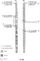
- FIG. 8 is a diagram illustrating a scenario in which a conflict results from two Ethernet PHYs indicating an ability to be timing master, and the conflict is resolved with the previous timing master remaining as timing master, in accordance with an embodiment of the invention.
- the PHYs 106 A and 106 B may have just completed link up with the PHY 106 A having been selected as IEEE 802.3 master. Accordingly, the register is_master in the PHY 106 A may be TRUE and the register is_master in the PHY 106 B may be FALSE.
- both timing sources 104 A and 104 B may assert the signal loc_clk_prop to their respective PHYs. Both of the PHYs 106 A and 106 B may transition to the HOLD state and the register pcs_clk_prop in each of the PHYs 106 A and 1068 may remain FALSE. A conflict may arise when assertion of signal 114 A is sufficiently close in time to signal 114 B. A conflict does not necessarily require signals 114 A and 114 B being asserted simultaneously.
- a conflict may arise when loc_clk_prop 114 A is asserted and then loc_clk_prop 114 B is asserted before PHY 106 B2 receives the indication that pcs_clk_prop has been asserted in the PHY 106 A1 .
- the signal hold_time_done is asserted in each of PHYs 106 A and 106 B.
- the register pcs_clk_prop is asserted in each of PHYs 106 A and 106 B.
- the register is_master is updated in each of PHYs 106 A and 106 B, but before the register is_master is updated, the state of the register is_master is copied to the register is_master_prev in each of the PHYs 106 A and 106 B.
- the register is_master_prev in PHY 106 A becomes (or remains) TRUE, the register is_master in PHY 106 A remains TRUE, the register is_master_prev in PHY 106 B becomes (or remains) FALSE, and the register is_master in PHY 106 B becomes TRUE.
- each of the PHYs 106 A and 106 B transmit an indication that it is propagating a clock to the other PHY that is suitable for the other PHY to synchronize to. These indications are received at time instant 4 .
- the register rem_clk_true in PHY 106 A is asserted in response to receiving the indication from the PHY 106 B.
- the register rem_clk_true in PHY 106 B is asserted in response to receiving the indication from the PHY 106 A.
- an Ethernet PHY 106 A may receive an indication, such as assertion of the signal 114 A, from a local timing source 104 A that a local clock is suitable for propagation by the Ethernet PHY 106 A to a link partner 106 B of the Ethernet PHY. In response to receiving the indication from the local timing source 104 A, a timer in the Ethernet PHY 106 A may be started.
- the Ethernet PHY 106 A receives, during a time period subsequent to starting the timer and before the timer reaches a predetermined value, an indication that the link partner 106 B is propagating a clock that is suitable for the Ethernet PHY 106 A to synchronize to, the Ethernet PHY 106 A may be configured as timing slave. In instances that the Ethernet PHY 106 A does not receive, during said time period subsequent to starting the timer and before the timer reaches a predetermined value, an indication that the link partner 106 B is propagating a clock that is suitable for the Ethernet PHY 106 A to synchronize to, the Ethernet PHY 106 A may be configured as timing master upon the timer reaching the predetermined value.
- the Ethernet PHY 106 A upon receiving an indication that the link partner 106 B is propagating a clock for the Ethernet PHY 106 A to synchronize to, the Ethernet PHY 106 B may be configured based on whether the Ethernet PHY 106 A was configured as timing master prior to receiving the indication from the local timing source 104 A. In instances that the Ethernet PHY 106 A was configured as timing master prior to receiving the indication from the local timing source 104 A, the indication from the link partner 106 B may be ignored and the Ethernet PHY 106 A may remain configured as timing master. In instances that the Ethernet PHY 106 A was configured as timing slave prior to receiving the indication from the local timing source 104 A, the Ethernet PHY 106 A may be reconfigured as timing slave.
- the indication received from the link partner 106 B may comprise a distinctively-encoded idle symbol.
- the Ethernet PHY 106 A is configured as timing master, transmitting an indication that the Ethernet PHY 106 A is propagating a clock suitable for the link partner 106 B to synchronize to.
- the indication transmitted by the Ethernet PHY 106 A may comprise a distinctively-encoded idle symbol.
- a configuration of the Ethernet PHY 106 A may transition from timing master to timing slave without changing a role of the Ethernet PHY 106 A as either IEEE 802.3 master or IEEE 802.3 slave.
- a configuration of the Ethernet PHY 106 A may transition from timing slave to timing master without changing a role of the Ethernet PHY 106 A as either IEEE 802.3 master or IEEE 802.3 slave.
- a clock of the Ethernet PHY 106 A may be synchronized to the clock propagated by the link partner.
- the Ethernet PHY 106 A is configured as timing master, upon receiving an indication from the local timing source 104 A that the local clock is no longer suitable for propagation to the link partner 106 B, the Ethernet PHY 106 A may transmit an indication that the Ethernet PHY 106 A is no longer propagating a clock that is suitable for the link partner 106 B to synchronize to.
- Another embodiment of the invention may provide a non-transitory computer readable medium, having stored thereon, a computer program having at least one code section executable by a computer, thereby causing the computer to perform the steps as described herein for a clock selection for synchronous Ethernet.
- the present invention may be realized in hardware, software, or a combination of hardware and software.
- the present invention may be realized in a centralized fashion in at least one computer system, or in a distributed fashion where different elements are spread across several interconnected computer systems. Any kind of computer system or other apparatus adapted for carrying out the methods described herein is suited.
- a typical combination of hardware and software may be a general-purpose computer system with a computer program that, when being loaded and executed, controls the computer system such that it carries out the methods described herein.
- the present invention may also be embedded in a computer program product, which comprises all the features enabling the implementation of the methods described herein, and which when loaded in a computer system is able to carry out these methods.
- Computer program in the present context means any expression, in any language, code or notation, of a set of instructions intended to cause a system having an information processing capability to perform a particular function either directly or after either or both of the following: a) conversion to another language, code or notation; b) reproduction in a different material form.
Abstract
Description
- U.S. Provisional Patent Application Ser. No. 61/388,106 filed on Sep. 30, 2010; and
- U.S. Provisional Patent Application Ser. No. 61/353,261 filed on Jun. 10, 2010.
- U.S. patent application Ser. No. 13/072,619 filed on Mar. 25, 2011
Claims (18)
Priority Applications (1)
| Application Number | Priority Date | Filing Date | Title |
|---|---|---|---|
| US13/158,277 US9215092B2 (en) | 2010-06-10 | 2011-06-10 | Clock selection for synchronous Ethernet |
Applications Claiming Priority (3)
| Application Number | Priority Date | Filing Date | Title |
|---|---|---|---|
| US35326110P | 2010-06-10 | 2010-06-10 | |
| US38810610P | 2010-09-30 | 2010-09-30 | |
| US13/158,277 US9215092B2 (en) | 2010-06-10 | 2011-06-10 | Clock selection for synchronous Ethernet |
Publications (2)
| Publication Number | Publication Date |
|---|---|
| US20110305248A1 US20110305248A1 (en) | 2011-12-15 |
| US9215092B2 true US9215092B2 (en) | 2015-12-15 |
Family
ID=45096171
Family Applications (3)
| Application Number | Title | Priority Date | Filing Date |
|---|---|---|---|
| US13/072,619 Abandoned US20110305165A1 (en) | 2010-06-10 | 2011-03-25 | Method and system for physical-layer handshaking for timing role transition |
| US13/156,228 Active 2031-11-29 US8565270B2 (en) | 2010-06-10 | 2011-06-08 | Phase and frequency re-lock in synchronous ethernet devices |
| US13/158,277 Active 2032-04-08 US9215092B2 (en) | 2010-06-10 | 2011-06-10 | Clock selection for synchronous Ethernet |
Family Applications Before (2)
| Application Number | Title | Priority Date | Filing Date |
|---|---|---|---|
| US13/072,619 Abandoned US20110305165A1 (en) | 2010-06-10 | 2011-03-25 | Method and system for physical-layer handshaking for timing role transition |
| US13/156,228 Active 2031-11-29 US8565270B2 (en) | 2010-06-10 | 2011-06-08 | Phase and frequency re-lock in synchronous ethernet devices |
Country Status (1)
| Country | Link |
|---|---|
| US (3) | US20110305165A1 (en) |
Cited By (2)
| Publication number | Priority date | Publication date | Assignee | Title |
|---|---|---|---|---|
| US10901936B2 (en) | 2016-07-21 | 2021-01-26 | International Business Machines Corporation | Staged power on/off sequence at the I/O phy level in an interchip interface |
| US11424901B2 (en) * | 2018-10-23 | 2022-08-23 | Intel Corporation | Method and apparatus for synchronous signaling between link partners in a high-speed interconnect |
Families Citing this family (8)
| Publication number | Priority date | Publication date | Assignee | Title |
|---|---|---|---|---|
| US9735905B2 (en) * | 2012-08-10 | 2017-08-15 | Avago Technologies General Ip (Singapore) Pte. Ltd. | Systems and methods for implementing bi-directional synchronization propagation |
| US20140126908A1 (en) * | 2012-11-07 | 2014-05-08 | Broadcom Corporation | System and Method for Enabling Energy Efficiency Over Ethernet Links in Consideration of Optical Network Transport Equipment |
| JP2017098588A (en) * | 2014-02-20 | 2017-06-01 | 日本電気株式会社 | Communication system, radio communication device, and radio communication method |
| US10237836B2 (en) | 2014-06-09 | 2019-03-19 | Parallel Wireless, Inc. | Frequency and phase synchronization using full duplex radios over wireless mesh networks |
| US9608751B2 (en) | 2015-03-18 | 2017-03-28 | Accedian Networks Inc. | Simplified synchronized Ethernet implementation |
| US9755774B1 (en) * | 2015-06-25 | 2017-09-05 | Juniper Networks, Inc. | Master/slave negotiation associated with a synchronous ethernet network |
| US10530560B2 (en) * | 2016-06-20 | 2020-01-07 | Nxp B.V. | Integrated circuit and method for processing synchronized network frames using a hardware synchronization circuit |
| US10122525B2 (en) * | 2017-03-10 | 2018-11-06 | Nokia Of America Corporation | Method and apparatus for performing a holdover function on a holdover line card |
Citations (17)
| Publication number | Priority date | Publication date | Assignee | Title |
|---|---|---|---|---|
| US5294921A (en) | 1991-11-12 | 1994-03-15 | Otis Elevator Company | Elevator communications bus analyzer |
| US6028853A (en) | 1996-06-07 | 2000-02-22 | Telefonaktiebolaget Lm Ericsson | Method and arrangement for radio communication |
| US20030002519A1 (en) * | 1996-05-01 | 2003-01-02 | Elastic Networks, Inc. | Information network access apparatus and methods for communicating information packets via telephone lines |
| US20030117899A1 (en) * | 2001-12-24 | 2003-06-26 | Eidson John C. | Distributed system time synchronization including a timing signal path |
| US6665316B1 (en) * | 1998-09-29 | 2003-12-16 | Agilent Technologies, Inc. | Organization of time synchronization in a distributed system |
| US20040028086A1 (en) * | 2002-08-12 | 2004-02-12 | Ali Ghiasi | Multi-stage high speed bit stream demultiplexer chip set having switchable master/slave relationship |
| US20040203936A1 (en) * | 2002-06-27 | 2004-10-14 | Minoru Ogino | Communication terminal, communication system, and computer program product |
| US20040258085A1 (en) * | 2003-06-19 | 2004-12-23 | Avi Costo | Network idle protocol with reduced channels |
| US6873630B1 (en) * | 1999-05-19 | 2005-03-29 | Sun Microsystems, Inc. | Method and apparatus for a multi-gigabit ethernet architecture |
| US20060291479A1 (en) * | 2005-06-28 | 2006-12-28 | Israel Sasson | System and method for high precision clock recovery over packet networks |
| US20080159270A1 (en) * | 2006-12-21 | 2008-07-03 | Zarlink Semiconductor Inc. | Integrated phase lock loop and network phy or switch |
| US20090092154A1 (en) * | 2007-10-05 | 2009-04-09 | Nxp B.V. | Method, system, and apparatus for extended rate/range communication over a communication network |
| US20100080248A1 (en) * | 2008-10-01 | 2010-04-01 | Nortel Networks Limited | Techniques for time transfer via signal encoding |
| US20110038283A1 (en) | 2008-04-23 | 2011-02-17 | Samsung Electronics Co., Ltd. | Network entry apparatus and method for relay station using full duplex in mobile communication system |
| US20110170645A1 (en) * | 2010-01-12 | 2011-07-14 | Barnette James D | Method for switching master/slave timing in a 1000base-t link without traffic disruption |
| US20110261917A1 (en) * | 2010-04-21 | 2011-10-27 | Lsi Corporation | Time Synchronization Using Packet-Layer and Physical-Layer Protocols |
| US20120026041A1 (en) * | 2010-08-02 | 2012-02-02 | Progeny Systems Corporation | Systems and methods for locating a target in a gps-denied environment |
Family Cites Families (1)
| Publication number | Priority date | Publication date | Assignee | Title |
|---|---|---|---|---|
| WO1996031033A2 (en) * | 1995-03-29 | 1996-10-03 | Philips Electronics N.V. | System for providing a predetermined timing relation between inputting and outputting of data; transmitter and receiver for such a system |
-
2011
- 2011-03-25 US US13/072,619 patent/US20110305165A1/en not_active Abandoned
- 2011-06-08 US US13/156,228 patent/US8565270B2/en active Active
- 2011-06-10 US US13/158,277 patent/US9215092B2/en active Active
Patent Citations (17)
| Publication number | Priority date | Publication date | Assignee | Title |
|---|---|---|---|---|
| US5294921A (en) | 1991-11-12 | 1994-03-15 | Otis Elevator Company | Elevator communications bus analyzer |
| US20030002519A1 (en) * | 1996-05-01 | 2003-01-02 | Elastic Networks, Inc. | Information network access apparatus and methods for communicating information packets via telephone lines |
| US6028853A (en) | 1996-06-07 | 2000-02-22 | Telefonaktiebolaget Lm Ericsson | Method and arrangement for radio communication |
| US6665316B1 (en) * | 1998-09-29 | 2003-12-16 | Agilent Technologies, Inc. | Organization of time synchronization in a distributed system |
| US6873630B1 (en) * | 1999-05-19 | 2005-03-29 | Sun Microsystems, Inc. | Method and apparatus for a multi-gigabit ethernet architecture |
| US20030117899A1 (en) * | 2001-12-24 | 2003-06-26 | Eidson John C. | Distributed system time synchronization including a timing signal path |
| US20040203936A1 (en) * | 2002-06-27 | 2004-10-14 | Minoru Ogino | Communication terminal, communication system, and computer program product |
| US20040028086A1 (en) * | 2002-08-12 | 2004-02-12 | Ali Ghiasi | Multi-stage high speed bit stream demultiplexer chip set having switchable master/slave relationship |
| US20040258085A1 (en) * | 2003-06-19 | 2004-12-23 | Avi Costo | Network idle protocol with reduced channels |
| US20060291479A1 (en) * | 2005-06-28 | 2006-12-28 | Israel Sasson | System and method for high precision clock recovery over packet networks |
| US20080159270A1 (en) * | 2006-12-21 | 2008-07-03 | Zarlink Semiconductor Inc. | Integrated phase lock loop and network phy or switch |
| US20090092154A1 (en) * | 2007-10-05 | 2009-04-09 | Nxp B.V. | Method, system, and apparatus for extended rate/range communication over a communication network |
| US20110038283A1 (en) | 2008-04-23 | 2011-02-17 | Samsung Electronics Co., Ltd. | Network entry apparatus and method for relay station using full duplex in mobile communication system |
| US20100080248A1 (en) * | 2008-10-01 | 2010-04-01 | Nortel Networks Limited | Techniques for time transfer via signal encoding |
| US20110170645A1 (en) * | 2010-01-12 | 2011-07-14 | Barnette James D | Method for switching master/slave timing in a 1000base-t link without traffic disruption |
| US20110261917A1 (en) * | 2010-04-21 | 2011-10-27 | Lsi Corporation | Time Synchronization Using Packet-Layer and Physical-Layer Protocols |
| US20120026041A1 (en) * | 2010-08-02 | 2012-02-02 | Progeny Systems Corporation | Systems and methods for locating a target in a gps-denied environment |
Non-Patent Citations (1)
| Title |
|---|
| Non-Final Office Action for Application No. 0250536 dated Apr. 3, 2013. |
Cited By (2)
| Publication number | Priority date | Publication date | Assignee | Title |
|---|---|---|---|---|
| US10901936B2 (en) | 2016-07-21 | 2021-01-26 | International Business Machines Corporation | Staged power on/off sequence at the I/O phy level in an interchip interface |
| US11424901B2 (en) * | 2018-10-23 | 2022-08-23 | Intel Corporation | Method and apparatus for synchronous signaling between link partners in a high-speed interconnect |
Also Published As
| Publication number | Publication date |
|---|---|
| US8565270B2 (en) | 2013-10-22 |
| US20110305165A1 (en) | 2011-12-15 |
| US20110305248A1 (en) | 2011-12-15 |
| US20110305173A1 (en) | 2011-12-15 |
Similar Documents
| Publication | Publication Date | Title |
|---|---|---|
| US9215092B2 (en) | Clock selection for synchronous Ethernet | |
| US9054823B2 (en) | Synchronous network device | |
| EP2524468B1 (en) | Method for switching master/slave timing in a 1000base-t link without traffic disruption | |
| CN103312428B (en) | For the method and apparatus of precision clock protocol synchronization network | |
| US20160156427A1 (en) | Clock recovery in a packet based network | |
| CN103916950A (en) | Time synchronization method and system | |
| US8619755B2 (en) | Systems and methods for providing a dual-master mode in a synchronous ethernet environment | |
| WO2013071807A1 (en) | Method, system and apparatus for implementing hybrid networking of multiple clock synchronization technologies | |
| US20100329284A1 (en) | Centralized node clock auto reconfiguration | |
| US6728492B1 (en) | 40 Gbit/s SONET framer with multiple clock-crossing capability | |
| EP1936848A1 (en) | Integrated phase lock loop and network PHY or switch | |
| KR20000071781A (en) | Network synchronization system and network synchronization method | |
| TWM605565U (en) | Distributed synchronization system | |
| JP4686740B2 (en) | Electronic device, method of frame synchronization, and mobile device | |
| JP2003032259A (en) | Gigabit ethernet multiplexing system | |
| WO2013097365A1 (en) | Method and network device for converging master clock sources | |
| TWM612938U (en) | Distributed synchronization system | |
| WO2017166969A1 (en) | Method and apparatus for sending 1588 message, and storage medium | |
| WO2016184018A1 (en) | Clock output method and apparatus | |
| JP2015173311A (en) | communication system | |
| WO2021164541A1 (en) | Communication device and clock synchronization method | |
| TWI769486B (en) | Distributed synchronization system | |
| JP2023554065A (en) | Method and apparatus for selecting a clock source | |
| TW202205105A (en) | Distributed synchronization system | |
| TWM618640U (en) | Distributed synchronization system |
Legal Events
| Date | Code | Title | Description |
|---|---|---|---|
| AS | Assignment |
Owner name: BROADCOM CORPORATION, CALIFORNIA Free format text: ASSIGNMENT OF ASSIGNORS INTEREST;ASSIGNORS:WANG, PEIQING;LIN, XIAOTONG;TAZEBAY, MEHMET;SIGNING DATES FROM 20110609 TO 20110610;REEL/FRAME:026660/0671 |
|
| STCF | Information on status: patent grant |
Free format text: PATENTED CASE |
|
| AS | Assignment |
Owner name: BANK OF AMERICA, N.A., AS COLLATERAL AGENT, NORTH CAROLINA Free format text: PATENT SECURITY AGREEMENT;ASSIGNOR:BROADCOM CORPORATION;REEL/FRAME:037806/0001 Effective date: 20160201 Owner name: BANK OF AMERICA, N.A., AS COLLATERAL AGENT, NORTH Free format text: PATENT SECURITY AGREEMENT;ASSIGNOR:BROADCOM CORPORATION;REEL/FRAME:037806/0001 Effective date: 20160201 |
|
| AS | Assignment |
Owner name: AVAGO TECHNOLOGIES GENERAL IP (SINGAPORE) PTE. LTD., SINGAPORE Free format text: ASSIGNMENT OF ASSIGNORS INTEREST;ASSIGNOR:BROADCOM CORPORATION;REEL/FRAME:041706/0001 Effective date: 20170120 Owner name: AVAGO TECHNOLOGIES GENERAL IP (SINGAPORE) PTE. LTD Free format text: ASSIGNMENT OF ASSIGNORS INTEREST;ASSIGNOR:BROADCOM CORPORATION;REEL/FRAME:041706/0001 Effective date: 20170120 |
|
| AS | Assignment |
Owner name: BROADCOM CORPORATION, CALIFORNIA Free format text: TERMINATION AND RELEASE OF SECURITY INTEREST IN PATENTS;ASSIGNOR:BANK OF AMERICA, N.A., AS COLLATERAL AGENT;REEL/FRAME:041712/0001 Effective date: 20170119 |
|
| AS | Assignment |
Owner name: AVAGO TECHNOLOGIES INTERNATIONAL SALES PTE. LIMITE Free format text: MERGER;ASSIGNOR:AVAGO TECHNOLOGIES GENERAL IP (SINGAPORE) PTE. LTD.;REEL/FRAME:047229/0408 Effective date: 20180509 |
|
| AS | Assignment |
Owner name: AVAGO TECHNOLOGIES INTERNATIONAL SALES PTE. LIMITE Free format text: CORRECTIVE ASSIGNMENT TO CORRECT THE EFFECTIVE DATE PREVIOUSLY RECORDED ON REEL 047229 FRAME 0408. ASSIGNOR(S) HEREBY CONFIRMS THE THE EFFECTIVE DATE IS 09/05/2018;ASSIGNOR:AVAGO TECHNOLOGIES GENERAL IP (SINGAPORE) PTE. LTD.;REEL/FRAME:047349/0001 Effective date: 20180905 |
|
| AS | Assignment |
Owner name: AVAGO TECHNOLOGIES INTERNATIONAL SALES PTE. LIMITE Free format text: CORRECTIVE ASSIGNMENT TO CORRECT THE PATENT NUMBER 9,385,856 TO 9,385,756 PREVIOUSLY RECORDED AT REEL: 47349 FRAME: 001. ASSIGNOR(S) HEREBY CONFIRMS THE MERGER;ASSIGNOR:AVAGO TECHNOLOGIES GENERAL IP (SINGAPORE) PTE. LTD.;REEL/FRAME:051144/0648 Effective date: 20180905 |
|
| MAFP | Maintenance fee payment |
Free format text: PAYMENT OF MAINTENANCE FEE, 4TH YEAR, LARGE ENTITY (ORIGINAL EVENT CODE: M1551); ENTITY STATUS OF PATENT OWNER: LARGE ENTITY Year of fee payment: 4 |
|
| MAFP | Maintenance fee payment |
Free format text: PAYMENT OF MAINTENANCE FEE, 8TH YEAR, LARGE ENTITY (ORIGINAL EVENT CODE: M1552); ENTITY STATUS OF PATENT OWNER: LARGE ENTITY Year of fee payment: 8 |