US9217458B2 - Prevailing torque locknut - Google Patents
Prevailing torque locknut Download PDFInfo
- Publication number
- US9217458B2 US9217458B2 US13/958,857 US201313958857A US9217458B2 US 9217458 B2 US9217458 B2 US 9217458B2 US 201313958857 A US201313958857 A US 201313958857A US 9217458 B2 US9217458 B2 US 9217458B2
- Authority
- US
- United States
- Prior art keywords
- locknut
- locking band
- locking
- fastener
- counterbore
- Prior art date
- Legal status (The legal status is an assumption and is not a legal conclusion. Google has not performed a legal analysis and makes no representation as to the accuracy of the status listed.)
- Expired - Fee Related, expires
Links
- 238000009434 installation Methods 0.000 description 5
- 239000000463 material Substances 0.000 description 4
- 230000013011 mating Effects 0.000 description 2
- 239000002184 metal Substances 0.000 description 2
- 229910000831 Steel Inorganic materials 0.000 description 1
- 230000004075 alteration Effects 0.000 description 1
- 230000006835 compression Effects 0.000 description 1
- 238000007906 compression Methods 0.000 description 1
- 238000010276 construction Methods 0.000 description 1
- 239000012530 fluid Substances 0.000 description 1
- 238000003780 insertion Methods 0.000 description 1
- 230000037431 insertion Effects 0.000 description 1
- 230000001681 protective effect Effects 0.000 description 1
- 229910001220 stainless steel Inorganic materials 0.000 description 1
- 239000010935 stainless steel Substances 0.000 description 1
- 239000010959 steel Substances 0.000 description 1
Images


Classifications
-
- F—MECHANICAL ENGINEERING; LIGHTING; HEATING; WEAPONS; BLASTING
- F16—ENGINEERING ELEMENTS AND UNITS; GENERAL MEASURES FOR PRODUCING AND MAINTAINING EFFECTIVE FUNCTIONING OF MACHINES OR INSTALLATIONS; THERMAL INSULATION IN GENERAL
- F16B—DEVICES FOR FASTENING OR SECURING CONSTRUCTIONAL ELEMENTS OR MACHINE PARTS TOGETHER, e.g. NAILS, BOLTS, CIRCLIPS, CLAMPS, CLIPS OR WEDGES; JOINTS OR JOINTING
- F16B39/00—Locking of screws, bolts or nuts
- F16B39/22—Locking of screws, bolts or nuts in which the locking takes place during screwing down or tightening
- F16B39/24—Locking of screws, bolts or nuts in which the locking takes place during screwing down or tightening by means of washers, spring washers, or resilient plates that lock against the object
- F16B39/26—Locking of screws, bolts or nuts in which the locking takes place during screwing down or tightening by means of washers, spring washers, or resilient plates that lock against the object with spring washers fastened to the nut or bolt-head
-
- F—MECHANICAL ENGINEERING; LIGHTING; HEATING; WEAPONS; BLASTING
- F16—ENGINEERING ELEMENTS AND UNITS; GENERAL MEASURES FOR PRODUCING AND MAINTAINING EFFECTIVE FUNCTIONING OF MACHINES OR INSTALLATIONS; THERMAL INSULATION IN GENERAL
- F16B—DEVICES FOR FASTENING OR SECURING CONSTRUCTIONAL ELEMENTS OR MACHINE PARTS TOGETHER, e.g. NAILS, BOLTS, CIRCLIPS, CLAMPS, CLIPS OR WEDGES; JOINTS OR JOINTING
- F16B39/00—Locking of screws, bolts or nuts
- F16B39/02—Locking of screws, bolts or nuts in which the locking takes place after screwing down
- F16B39/12—Locking of screws, bolts or nuts in which the locking takes place after screwing down by means of locknuts
- F16B39/14—Locking of screws, bolts or nuts in which the locking takes place after screwing down by means of locknuts made of thin sheet material or formed as spring-washers
-
- F—MECHANICAL ENGINEERING; LIGHTING; HEATING; WEAPONS; BLASTING
- F16—ENGINEERING ELEMENTS AND UNITS; GENERAL MEASURES FOR PRODUCING AND MAINTAINING EFFECTIVE FUNCTIONING OF MACHINES OR INSTALLATIONS; THERMAL INSULATION IN GENERAL
- F16B—DEVICES FOR FASTENING OR SECURING CONSTRUCTIONAL ELEMENTS OR MACHINE PARTS TOGETHER, e.g. NAILS, BOLTS, CIRCLIPS, CLAMPS, CLIPS OR WEDGES; JOINTS OR JOINTING
- F16B39/00—Locking of screws, bolts or nuts
- F16B39/02—Locking of screws, bolts or nuts in which the locking takes place after screwing down
- F16B39/20—Locking of screws, bolts or nuts in which the locking takes place after screwing down by means of steel wire or the like
Definitions
- the present invention relates to locknuts, and more particularly to locknuts including a spring coil or band.
- All-metal prevailing torque locknuts are often specified for use in extreme temperature and/or high vibration applications.
- One of the more common types of locknuts has distorted threads to provide an interference fit with the mating male thread.
- a description of this type of locknut may be found at http://www.fastenermart.com/html/all-metal-lock-nuts.html.
- Locknuts with distorted threads have a very high prevailing torque which, in some cases, may be as high as the design torque of the bolted joint itself. This high prevailing torque makes installation of the locknut slow and difficult and control of joint clamp-up problematic. Further, if the joint consists of a number of all-metal locknuts, it is difficult to maintain uniform or desired clamp-up at all of the bolt locations. This can lead to structural weakness and to leaks in applications where fluid seals require uniform clamp-up to maintain proper gasket or joint compression.
- locknut is a split beam or flexloc locknut.
- a description of this type of locknut may be found at http://www.fastenermart.com/html/flexloc-nuts.html.
- This type of locknut has a nut body that includes a top portion with six narrow slots spaced 60° apart, thereby forming six flexing beams. These beams are bent inward slightly to provide a grip on the male threaded member.
- This type of locknut is relatively expensive compared to the distorted thread style locknut.
- locknuts comprising a highly function, reusable, yet relatively inexpensive prevailing torque locknut.
- the locknut of the present includes a nut body and a locking band.
- the nut body has a threaded portion and an unthreaded counterbore.
- the locking band includes a coil portion and first and second tangs that extend from the coil portion.
- the locking band is located within the counterbore.
- the first and second tangs extend tangentially from the coil portion and engage the counterbore, so that the first tang bears against the counterbore when the locknut is turned in a first direction, and the second tang bears against the counterbore when the locknut is turned in a second direction.
- the counterbore includes a collar and a shoulder.
- the locking band is located below the shoulder, and the locknut includes a retainer on the shoulder to retain the locking band in position.
- the collar can be swaged to secure the retainer on the shoulder.
- the present locknut provides improved performance compared to known prevailing torque locknuts.
- the locknut can be economically manufactured in materials suitable for extreme temperature service. Additionally, the locknut provides good vibration resistance, is reusable, and will not gall or seize. Further, the locknut provides consistent prevailing torque to improve joint clamp-up consistency.
- FIG. 1 is a perspective, exploded view of the current embodiment of the locknut
- FIG. 2 is a cross-sectional view of the assembled locknut, taken along line II-II in FIG. 1 ;
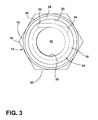
- FIG. 3 is a top plan view of the locknut without the retainer and without the shoulder swaged.
- FIGS. 1-3 A locknut constructed in accordance with a current embodiment of the invention is illustrated in FIGS. 1-3 and generally designated 10 .
- the locknut 10 is a prevailing torque type fastener that creates frictional interference between the locknut and a mating component, so that there is resistance to rotation during both installation and removal.
- the locknut 10 includes a nut body 12 , a locking element, spring, coil, or band 14 , and a retainer 40 .
- the nut body 12 includes a hex-shaped outer portion 16 configured to be engaged and driven by a conventional driving tool (not shown).
- the hex-shaped portion 16 includes a plurality of corners 18 and a plurality of flats 20 extending therebetween.
- the nut body 12 may be square, otherwise polygonal, or any other shape adapted to be engaged by a conventional or special driving tool, now known or later developed.
- the nut body 12 includes a threaded portion 22 and an unthreaded portion 24 defining a counterbore, recess, or pocket.
- the counterbore 24 includes a sidewall 25 , a shoulder 26 , and a collar 28 .
- the shoulder 26 separates the sidewall 25 and the collar 28 .
- the internal diameter of the sidewall 25 of the counterbore 24 is smaller than the internal diameter of the collar 28 .
- the sidewall 25 is an uninterrupted cylinder.
- the locking band 14 includes a coil portion 30 having a circular cross-section, a first tang or end portion 32 , and a second tang or end portion 34 .
- the first and second tangs 32 , 34 extend tangentially from the coil portion 30 .
- the first and second tangs 32 , 34 are straight, but other configurations are possible.
- the ends of the tangs 32 , 34 are “sharp”, for example as would occur from cutting, or otherwise configured to “bite” into the uninterrupted cylindrical sidewall 25 . This configuration is sufficient to prevent each tang 32 , 34 from moving in one direction with respect to the nut body 12 .
- the locking band 14 includes one or more turns.
- the locking band 14 may include less than one turn, in which case the first tang 32 and the second tang 34 may overlap.
- the locking band 14 has two full turns, and the first and second tangs 32 , 34 are radially separated.
- the locking band 14 is fabricated of wire or other stock having a circular cross section. Other cross-sectional shapes are possible, including square, rectangular, ovate, and triangular. The cross-sectional thickness (e.g. diameter), regardless of shape, is equal to or less than the thread pitch of the threaded portion 33 . In the current embodiment, the locking band 14 is symmetrical to simplify assembly of the locknut 10 .
- the retainer 40 is a washer-shaped or ring-shaped member having a central opening 42 .
- the locking band 14 is inserted into the unthreaded counterbore 24 of the nut body 12 .
- the tangs 32 , 34 must be flexed at least slightly to insert the locking band 14 within the nut body 12 .
- the locking band 14 may be lightly pressed into the counterbore 24 .
- the first and second tangs 32 , 34 contact the interior surface of the counterbore 24 .
- the light press fit of the locking band 14 within the counterbore 24 develops or sets the prevailing torque for the locknut 10 .
- the locking band 14 is indexed to the threaded portion 22 of the nut body 12 . Consequently, when the locknut 10 is threaded onto the externally threaded member, the threaded member smoothly engages both the threaded portion 22 and the locking band 14 .
- the locking band 14 is positioned below the shoulder 28 .
- the retainer 40 is positioned against the shoulder 28 , over the locking band 14 , and encircled by the collar 26 .
- the collar 26 of the nut body 12 may be swaged or otherwise deformed over top of the retainer 40 .
- any suitable means for deforming the collar 26 over the retainer 40 or otherwise securing the retainer in position may be used.
- the retainer 40 and the locking band 44 are sized to fit both the desired nut body 12 and the externally threaded member, for example, a standard bolt.
- the outside diameter of the retainer 40 may be sized to fit within the internal diameter of the collar 26
- the central opening 42 may be sized to match or provide clearance to the externally threaded member.
- the central opening 42 may be sized to provide interference with the minor diameter of the externally threaded member so as to seal off the interior of the nut body 12 from the environment.
- the retainer may be formed as a cap (i.e. without a central opening 42 ) to provide an integral protective cover for the locknut 10 .
- the diameter of the locking band 14 provides sufficient clearance to enable the locking band 14 to slightly elastically expand when the locknut 10 is mounted on the threaded member.
- the thickness of the wire of the locking band 14 is no greater than the pitch of the threaded portion 22 , so that the coils of the locking band 14 can fit within the threads of the externally threaded member. Additionally, the locking band 14 is wound to have the same direction as the threaded portion 22 .
- the nut body 12 , the locking band 14 , and the retainer 40 may be manufactured from any suitable materials.
- the locking band 14 may be manufactured of relatively low-cost materials such as round steel or spring temper wire.
- Angular movement of the tangs 32 , 34 is resisted due to contact of the tangs 32 , 34 with the sidewall 25 of the counterbore 24 .
- the locknut 10 will rotate.
- the end of the second tang 34 bears against the sidewall 25 of the counterbore 24 .
- the end of the first tang 32 bears against the sidewall 25 of the counterbore 24 .
- the nut body 12 is rotated in a first or generally clockwise direction.
- the externally threaded member causes the coil portion 30 of the locking band 14 to expand elastically by a small amount.
- Rotating the nut body 12 in the clockwise direction presses the end of the second tang 34 against the sidewall 25 of the counterbore 24 , thereby resisting rotation of the locking band 14 while the threaded member is installed.
- the expansion of the locking band 14 on the threaded member provides substantial frictional grip to resist loosening torque under vibration that may be experienced when in use.
- the nut body 12 is rotated in a second or generally counterclockwise direction. Rotating the nut body 12 in the counterclockwise direction presses the end of the first tang 32 against the surface of the counterbore 24 . As with installation, this force resists rotation of the locking band 14 .
- the locknut 10 described herein provides consistent and substantially equal prevailing torque during both installation and removal.
- the locknut 10 smoothly engages the threaded member without excessive torque.
- the amount of prevailing torque can be controlled by adjusting one or more of the initial diameter of the locking band 14 , the number of turns in the locking band, the thickness (e.g. diameter) of the locking band wire, and the amount of interference between the tang ends 32 , 34 with the counterbore 24 .
- the present locknut 10 is simple to use, can be reused multiple times without loss of effectiveness, may be scaled to meet specific needs, and does not damage the bolt threads. Further, the locknut 10 may be economically manufactured in material suitable for extreme temperature service, provides vibration resistance, will not gall or seize, and provides consistent prevailing torque to improve joint clamp-up consistency.
Abstract
Description
Claims (15)
Priority Applications (2)
| Application Number | Priority Date | Filing Date | Title |
|---|---|---|---|
| US13/958,857 US9217458B2 (en) | 2013-08-05 | 2013-08-05 | Prevailing torque locknut |
| PCT/US2014/036476 WO2015020705A1 (en) | 2013-08-05 | 2014-05-02 | Prevailing torque locknut |
Applications Claiming Priority (1)
| Application Number | Priority Date | Filing Date | Title |
|---|---|---|---|
| US13/958,857 US9217458B2 (en) | 2013-08-05 | 2013-08-05 | Prevailing torque locknut |
Publications (2)
| Publication Number | Publication Date |
|---|---|
| US20150037117A1 US20150037117A1 (en) | 2015-02-05 |
| US9217458B2 true US9217458B2 (en) | 2015-12-22 |
Family
ID=50943556
Family Applications (1)
| Application Number | Title | Priority Date | Filing Date |
|---|---|---|---|
| US13/958,857 Expired - Fee Related US9217458B2 (en) | 2013-08-05 | 2013-08-05 | Prevailing torque locknut |
Country Status (2)
| Country | Link |
|---|---|
| US (1) | US9217458B2 (en) |
| WO (1) | WO2015020705A1 (en) |
Families Citing this family (1)
| Publication number | Priority date | Publication date | Assignee | Title |
|---|---|---|---|---|
| CN111795058B (en) * | 2020-07-06 | 2022-04-12 | 石卫东 | Anti-loosening nut |
Citations (60)
| Publication number | Priority date | Publication date | Assignee | Title |
|---|---|---|---|---|
| US152249A (en) | 1874-06-23 | Improvement in nut-locks | ||
| US422027A (en) | 1890-02-25 | Robert marshall | ||
| US637360A (en) | 1899-06-02 | 1899-11-21 | Spiral Nut Lock Company | Nut-lock. |
| US900589A (en) | 1907-12-18 | 1908-10-06 | Charles E Ratcliffe | Nut-lock. |
| GB190904780A (en) | 1909-02-26 | 1909-05-27 | Edward Raymond Peal | Improvements in or relating to Lock Nuts. |
| US960349A (en) | 1909-09-22 | 1910-06-07 | Jean Sinia Lafleur | Nut-lock. |
| US988911A (en) | 1909-07-31 | 1911-04-04 | Alfred Ernest Terry | Screw locking nut. |
| GB191027703A (en) | 1909-12-01 | 1911-06-15 | Cfcmug | Improved Regulating Device for Mixing Fluids in given Proportions and for Measuring the same. |
| US1017845A (en) | 1911-06-22 | 1912-02-20 | Aaron A Brown | Nut-lock. |
| US1081965A (en) | 1913-01-20 | 1913-12-23 | Marcus Kester | Nut-lock. |
| US1172722A (en) | 1914-06-05 | 1916-02-22 | William R Millard | Nut-lock. |
| US1179446A (en) | 1915-09-14 | 1916-04-18 | Carl A Fettig | Nut-lock. |
| US1267656A (en) | 1917-11-22 | 1918-05-28 | Thorwald Goserud | Lock-nut. |
| US1440324A (en) | 1921-07-15 | 1922-12-26 | Whitaker Charles | Device for locking nuts on bolts |
| GB221456A (en) | 1924-06-02 | 1924-09-11 | Oskar Arvid Eklund | Improvements in or relating to self locking nuts |
| US1550282A (en) | 1924-08-18 | 1925-08-18 | Rennerfelt Ture Gustaf | Self-locking nut |
| US1630958A (en) | 1924-10-18 | 1927-05-31 | John L Mauch | Nut lock and the like |
| US1830918A (en) | 1928-03-17 | 1931-11-10 | Sundh August | Self-holding nut |
| US1830919A (en) | 1928-07-13 | 1931-11-10 | Sundh August | Self-holding device for nuts |
| US1830920A (en) | 1928-07-13 | 1931-11-10 | Sundh August | Self-holding device for nuts |
| US1909400A (en) | 1930-12-24 | 1933-05-16 | Safety Nut Corp | Brake lock |
| US1929169A (en) | 1931-09-21 | 1933-10-03 | Hall Albert | Brake lock |
| CH209896A (en) | 1939-04-20 | 1940-05-15 | Ebosa Sa | Urgent screw connection. |
| US2233889A (en) | 1938-06-20 | 1941-03-04 | Hood James Bruce | Screw threaded element |
| US2255948A (en) | 1938-01-28 | 1941-09-16 | Elastic Stop Nut Corp | Self-locking socket nut |
| US2320032A (en) | 1941-10-20 | 1943-05-25 | Charles C Akin | Lock nut |
| US2367929A (en) | 1943-05-24 | 1945-01-23 | Colman Henry James | Self-locking nut |
| US2432805A (en) | 1944-02-14 | 1947-12-16 | Oliver Edwin Simmonds | Lock nut |
| US2562621A (en) | 1950-02-28 | 1951-07-31 | Magnus C Larson | Nut lock |
| US2587560A (en) | 1945-05-25 | 1952-02-26 | Widmer Rene | Spring actuated lock nut |
| FR1032330A (en) | 1951-02-12 | 1953-07-01 | lock nut | |
| FR1101421A (en) | 1954-05-28 | 1955-10-06 | lock nut | |
| FR1108071A (en) | 1954-07-01 | 1956-01-09 | lock nut | |
| US2823725A (en) | 1957-06-04 | 1958-02-18 | Trinca Frederick | Locking devices |
| FR1377030A (en) | 1963-12-07 | 1964-10-31 | Nut Clip Collar | |
| US3391720A (en) | 1966-10-12 | 1968-07-09 | Morse Milton | Spiral shaped threaded locking fastener |
| US3565149A (en) | 1969-01-02 | 1971-02-23 | Gen Electric | Spring lock |
| US3589423A (en) | 1969-06-10 | 1971-06-29 | Norco Inc | Locking-type machine nut |
| US3701372A (en) | 1967-04-07 | 1972-10-31 | Lamson & Sessions Co | Lock bolt and method of making the same |
| US4004486A (en) * | 1975-12-08 | 1977-01-25 | Dzus Fastener Co., Inc. | Quick release fastener |
| US4069855A (en) | 1977-03-04 | 1978-01-24 | Tridair Industries | Captive panel fastener |
| US4334438A (en) | 1979-03-09 | 1982-06-15 | Nissan Motor Company, Limited | Clearance adjusting mechanism |
| US4357726A (en) | 1977-03-25 | 1982-11-09 | Amerace Corporation | Method of making self-locking nut |
| AT375452B (en) | 1982-03-08 | 1984-08-10 | Schleicher Richard | SAFETY SCREW NUT |
| FR2544030A1 (en) | 1983-04-06 | 1984-10-12 | Kontakta Alkatreszgyar | Self-locking fastening element for threaded rods |
| US4692078A (en) | 1982-08-30 | 1987-09-08 | Shur-Lok International S.A. | Nut device having automatic positive locking |
| US4983085A (en) | 1989-09-26 | 1991-01-08 | Northrop Corporation | Threaded lockable fastener with swaged collar |
| US5449259A (en) | 1994-03-11 | 1995-09-12 | Warn Industries, Inc. | Thread locking device |
| US5529348A (en) | 1995-02-27 | 1996-06-25 | Dana Corporation | Spring lock connector |
| US6015251A (en) | 1998-02-19 | 2000-01-18 | Chung; Boo Kang | Secure threaded fastener |
| JP2003307210A (en) | 2002-02-15 | 2003-10-31 | Eco Tool:Kk | Locking nut structure |
| EP1760334A1 (en) | 2004-06-07 | 2007-03-07 | Taijiro Soeda | Falling-off prevention device and loosening prevention nut |
| US20090095359A1 (en) | 2007-10-15 | 2009-04-16 | Flow-Rite Controls, Ltd. | Stem-mounted tire inflation pressure regulator |
| US20090097940A1 (en) | 2007-10-15 | 2009-04-16 | Flow-Rite Controls, Ltd. | Locking threaded connection |
| US20100266364A1 (en) | 2009-04-17 | 2010-10-21 | Flow-Rite Controls, Ltd. | Locking threaded fastener |
| US8016532B2 (en) | 2006-12-07 | 2011-09-13 | Powerrex Corporation Co., Ltd. | Anti-loose lock nut |
| US20120301246A1 (en) | 2011-05-23 | 2012-11-29 | Flow-Rite Controls, Ltd. | Locking threaded fastener |
| US8425168B2 (en) | 2010-09-13 | 2013-04-23 | Flow-Rite Controls, Ltd. | Locking threaded fastener |
| US8439616B2 (en) | 2011-05-23 | 2013-05-14 | Flow-Rite Controls, Ltd. | Locking threaded fastener |
| WO2013112254A1 (en) | 2012-01-27 | 2013-08-01 | Flow-Rite Controls, Ltd. | Locking threaded fastener |
-
2013
- 2013-08-05 US US13/958,857 patent/US9217458B2/en not_active Expired - Fee Related
-
2014
- 2014-05-02 WO PCT/US2014/036476 patent/WO2015020705A1/en active Application Filing
Patent Citations (61)
| Publication number | Priority date | Publication date | Assignee | Title |
|---|---|---|---|---|
| US152249A (en) | 1874-06-23 | Improvement in nut-locks | ||
| US422027A (en) | 1890-02-25 | Robert marshall | ||
| US637360A (en) | 1899-06-02 | 1899-11-21 | Spiral Nut Lock Company | Nut-lock. |
| US900589A (en) | 1907-12-18 | 1908-10-06 | Charles E Ratcliffe | Nut-lock. |
| GB190904780A (en) | 1909-02-26 | 1909-05-27 | Edward Raymond Peal | Improvements in or relating to Lock Nuts. |
| US988911A (en) | 1909-07-31 | 1911-04-04 | Alfred Ernest Terry | Screw locking nut. |
| US960349A (en) | 1909-09-22 | 1910-06-07 | Jean Sinia Lafleur | Nut-lock. |
| GB191027703A (en) | 1909-12-01 | 1911-06-15 | Cfcmug | Improved Regulating Device for Mixing Fluids in given Proportions and for Measuring the same. |
| US1017845A (en) | 1911-06-22 | 1912-02-20 | Aaron A Brown | Nut-lock. |
| US1081965A (en) | 1913-01-20 | 1913-12-23 | Marcus Kester | Nut-lock. |
| US1172722A (en) | 1914-06-05 | 1916-02-22 | William R Millard | Nut-lock. |
| US1179446A (en) | 1915-09-14 | 1916-04-18 | Carl A Fettig | Nut-lock. |
| US1267656A (en) | 1917-11-22 | 1918-05-28 | Thorwald Goserud | Lock-nut. |
| US1440324A (en) | 1921-07-15 | 1922-12-26 | Whitaker Charles | Device for locking nuts on bolts |
| GB221456A (en) | 1924-06-02 | 1924-09-11 | Oskar Arvid Eklund | Improvements in or relating to self locking nuts |
| US1550282A (en) | 1924-08-18 | 1925-08-18 | Rennerfelt Ture Gustaf | Self-locking nut |
| US1630958A (en) | 1924-10-18 | 1927-05-31 | John L Mauch | Nut lock and the like |
| US1830918A (en) | 1928-03-17 | 1931-11-10 | Sundh August | Self-holding nut |
| US1830919A (en) | 1928-07-13 | 1931-11-10 | Sundh August | Self-holding device for nuts |
| US1830920A (en) | 1928-07-13 | 1931-11-10 | Sundh August | Self-holding device for nuts |
| US1909400A (en) | 1930-12-24 | 1933-05-16 | Safety Nut Corp | Brake lock |
| US1929169A (en) | 1931-09-21 | 1933-10-03 | Hall Albert | Brake lock |
| US2255948A (en) | 1938-01-28 | 1941-09-16 | Elastic Stop Nut Corp | Self-locking socket nut |
| US2233889A (en) | 1938-06-20 | 1941-03-04 | Hood James Bruce | Screw threaded element |
| CH209896A (en) | 1939-04-20 | 1940-05-15 | Ebosa Sa | Urgent screw connection. |
| US2320032A (en) | 1941-10-20 | 1943-05-25 | Charles C Akin | Lock nut |
| US2367929A (en) | 1943-05-24 | 1945-01-23 | Colman Henry James | Self-locking nut |
| US2432805A (en) | 1944-02-14 | 1947-12-16 | Oliver Edwin Simmonds | Lock nut |
| US2587560A (en) | 1945-05-25 | 1952-02-26 | Widmer Rene | Spring actuated lock nut |
| US2562621A (en) | 1950-02-28 | 1951-07-31 | Magnus C Larson | Nut lock |
| FR1032330A (en) | 1951-02-12 | 1953-07-01 | lock nut | |
| FR1101421A (en) | 1954-05-28 | 1955-10-06 | lock nut | |
| FR1108071A (en) | 1954-07-01 | 1956-01-09 | lock nut | |
| US2823725A (en) | 1957-06-04 | 1958-02-18 | Trinca Frederick | Locking devices |
| FR1377030A (en) | 1963-12-07 | 1964-10-31 | Nut Clip Collar | |
| US3391720A (en) | 1966-10-12 | 1968-07-09 | Morse Milton | Spiral shaped threaded locking fastener |
| US3701372A (en) | 1967-04-07 | 1972-10-31 | Lamson & Sessions Co | Lock bolt and method of making the same |
| US3565149A (en) | 1969-01-02 | 1971-02-23 | Gen Electric | Spring lock |
| US3589423A (en) | 1969-06-10 | 1971-06-29 | Norco Inc | Locking-type machine nut |
| US4004486A (en) * | 1975-12-08 | 1977-01-25 | Dzus Fastener Co., Inc. | Quick release fastener |
| US4069855A (en) | 1977-03-04 | 1978-01-24 | Tridair Industries | Captive panel fastener |
| US4357726A (en) | 1977-03-25 | 1982-11-09 | Amerace Corporation | Method of making self-locking nut |
| US4334438A (en) | 1979-03-09 | 1982-06-15 | Nissan Motor Company, Limited | Clearance adjusting mechanism |
| AT375452B (en) | 1982-03-08 | 1984-08-10 | Schleicher Richard | SAFETY SCREW NUT |
| US4692078A (en) | 1982-08-30 | 1987-09-08 | Shur-Lok International S.A. | Nut device having automatic positive locking |
| FR2544030A1 (en) | 1983-04-06 | 1984-10-12 | Kontakta Alkatreszgyar | Self-locking fastening element for threaded rods |
| US4983085A (en) | 1989-09-26 | 1991-01-08 | Northrop Corporation | Threaded lockable fastener with swaged collar |
| US5449259A (en) | 1994-03-11 | 1995-09-12 | Warn Industries, Inc. | Thread locking device |
| US5529348A (en) | 1995-02-27 | 1996-06-25 | Dana Corporation | Spring lock connector |
| US6015251A (en) | 1998-02-19 | 2000-01-18 | Chung; Boo Kang | Secure threaded fastener |
| JP2003307210A (en) | 2002-02-15 | 2003-10-31 | Eco Tool:Kk | Locking nut structure |
| EP1760334A1 (en) | 2004-06-07 | 2007-03-07 | Taijiro Soeda | Falling-off prevention device and loosening prevention nut |
| US8016532B2 (en) | 2006-12-07 | 2011-09-13 | Powerrex Corporation Co., Ltd. | Anti-loose lock nut |
| US20090097940A1 (en) | 2007-10-15 | 2009-04-16 | Flow-Rite Controls, Ltd. | Locking threaded connection |
| US20090095359A1 (en) | 2007-10-15 | 2009-04-16 | Flow-Rite Controls, Ltd. | Stem-mounted tire inflation pressure regulator |
| US20100266364A1 (en) | 2009-04-17 | 2010-10-21 | Flow-Rite Controls, Ltd. | Locking threaded fastener |
| US8021093B2 (en) | 2009-04-17 | 2011-09-20 | Flow-Rite Controls, Ltd. | Locking threaded fastener |
| US8425168B2 (en) | 2010-09-13 | 2013-04-23 | Flow-Rite Controls, Ltd. | Locking threaded fastener |
| US20120301246A1 (en) | 2011-05-23 | 2012-11-29 | Flow-Rite Controls, Ltd. | Locking threaded fastener |
| US8439616B2 (en) | 2011-05-23 | 2013-05-14 | Flow-Rite Controls, Ltd. | Locking threaded fastener |
| WO2013112254A1 (en) | 2012-01-27 | 2013-08-01 | Flow-Rite Controls, Ltd. | Locking threaded fastener |
Non-Patent Citations (8)
| Title |
|---|
| International Search Report and Written Opinion for International Application No. PCT/US2011/049254, mailed Oct. 28, 2011. |
| International Search Report and Written Opinion for International Application No. PCT/US2012/037183, mailed Aug. 6, 2012. |
| International Search Report and Written Opinion for PCT/US2012/071114, dated Mar. 25, 2013. |
| International Search Report and Written Opinion from PCT/US2014/036476 dated Jul. 31, 2014. |
| PCT Notification of Transmittal of the International Search Report and Written Opinion of the International Searching Authority or the Declaration, International Search Report, Written Opinion of the International Searching Authority dated Dec. 19, 2008 in PCT Application No. PCT/US2008/076155. |
| PCT Notification of Transmittal of the International Search Report and Written Opinion of the International Searching Authority or the Declaration, International Search Report, Written Opinion of the International Searching Authority dated May 31, 2010 in PCT Application No. PCT/US2010/026196. |
| U.S. Appl. No. 12/880,580, filed Sep. 13, 2010, entitled "Locking Threaded Fastener". |
| United States Statutory Invention Registration No. H1588, published Sep. 3, 1996, entitled "Helical Spring Fastener". |
Also Published As
| Publication number | Publication date |
|---|---|
| WO2015020705A1 (en) | 2015-02-12 |
| US20150037117A1 (en) | 2015-02-05 |
Similar Documents
| Publication | Publication Date | Title |
|---|---|---|
| EP2419651B1 (en) | Locking threaded fastener | |
| EP3032119B1 (en) | Anti-loosening bolt assembly | |
| US9188261B2 (en) | Safety connecting device, in particular for piping, an end-coupler for such device, and a method for manufacturing a nut therefor | |
| US9022070B2 (en) | Bolted valve control element | |
| KR102048264B1 (en) | A Locknut | |
| MX2007010920A (en) | Self-attaching fastenner and fastener and panel assembly. | |
| US2883228A (en) | Closure fastener | |
| US20120301246A1 (en) | Locking threaded fastener | |
| US8348578B2 (en) | Engagement unit for attaching and for engaging a threaded bolt | |
| EP2864648B1 (en) | Locknut with cage | |
| EP2864647B1 (en) | Nut lock | |
| US9217458B2 (en) | Prevailing torque locknut | |
| US20130266395A1 (en) | Locknut with segmented ring | |
| US9970473B2 (en) | Fastening element | |
| CN106246702B (en) | Deformable body and fastening structure comprising deformable body and creep-resistant ring | |
| AU2012367224A1 (en) | Locking threaded fastener | |
| WO2017192205A1 (en) | Locknut with locking coil and coil support | |
| RU2581977C1 (en) | Nut | |
| JP2023175593A (en) | Looseness prevention nut | |
| US20170350546A1 (en) | Locking ratchet effect clamp |
Legal Events
| Date | Code | Title | Description |
|---|---|---|---|
| AS | Assignment |
Owner name: FLOW-RITE CONTROLS, LTD., MICHIGAN Free format text: ASSIGNMENT OF ASSIGNORS INTEREST;ASSIGNOR:CAMPAU, DANIEL N.;REEL/FRAME:030941/0015 Effective date: 20130731 |
|
| AS | Assignment |
Owner name: LOCKON LLC, MICHIGAN Free format text: NUNC PRO TUNC ASSIGNMENT;ASSIGNOR:FLOW-RITE CONTROLS, LTD.;REEL/FRAME:033622/0953 Effective date: 20140827 |
|
| STCF | Information on status: patent grant |
Free format text: PATENTED CASE |
|
| AS | Assignment |
Owner name: FLOW-RITE CONTROLS, LTD., MICHIGAN Free format text: ASSIGNMENT OF ASSIGNORS INTEREST;ASSIGNOR:LOCKON LLC;REEL/FRAME:045507/0429 Effective date: 20180326 |
|
| FEPP | Fee payment procedure |
Free format text: MAINTENANCE FEE REMINDER MAILED (ORIGINAL EVENT CODE: REM.); ENTITY STATUS OF PATENT OWNER: SMALL ENTITY |
|
| LAPS | Lapse for failure to pay maintenance fees |
Free format text: PATENT EXPIRED FOR FAILURE TO PAY MAINTENANCE FEES (ORIGINAL EVENT CODE: EXP.); ENTITY STATUS OF PATENT OWNER: SMALL ENTITY |
|
| STCH | Information on status: patent discontinuation |
Free format text: PATENT EXPIRED DUE TO NONPAYMENT OF MAINTENANCE FEES UNDER 37 CFR 1.362 |
|
| FP | Lapsed due to failure to pay maintenance fee |
Effective date: 20191222 |