US9217558B2 - Modular illumination device - Google Patents
Modular illumination device Download PDFInfo
- Publication number
- US9217558B2 US9217558B2 US12/735,602 US73560209A US9217558B2 US 9217558 B2 US9217558 B2 US 9217558B2 US 73560209 A US73560209 A US 73560209A US 9217558 B2 US9217558 B2 US 9217558B2
- Authority
- US
- United States
- Prior art keywords
- illumination device
- button
- light source
- inner body
- body portion
- Prior art date
- Legal status (The legal status is an assumption and is not a legal conclusion. Google has not performed a legal analysis and makes no representation as to the accuracy of the status listed.)
- Expired - Fee Related, expires
Links
- 238000005286 illumination Methods 0.000 title claims abstract description 93
- 230000000994 depressogenic effect Effects 0.000 claims description 23
- 238000002360 preparation method Methods 0.000 claims description 19
- 230000000881 depressing effect Effects 0.000 claims description 8
- 230000008672 reprogramming Effects 0.000 claims description 5
- 239000011521 glass Substances 0.000 claims description 3
- 230000001427 coherent effect Effects 0.000 claims 6
- 230000011664 signaling Effects 0.000 description 8
- 239000000463 material Substances 0.000 description 7
- 230000000712 assembly Effects 0.000 description 4
- 238000000429 assembly Methods 0.000 description 4
- 238000010586 diagram Methods 0.000 description 4
- 229910003460 diamond Inorganic materials 0.000 description 4
- 239000010432 diamond Substances 0.000 description 4
- 239000003365 glass fiber Chemical class 0.000 description 4
- 238000000034 method Methods 0.000 description 4
- 230000035939 shock Effects 0.000 description 4
- 229920000049 Carbon (fiber) Chemical class 0.000 description 3
- 230000006978 adaptation Effects 0.000 description 3
- 239000004917 carbon fiber Chemical class 0.000 description 3
- 239000002131 composite material Substances 0.000 description 3
- -1 for example Chemical compound 0.000 description 3
- 230000013011 mating Effects 0.000 description 3
- 238000012986 modification Methods 0.000 description 3
- 230000004048 modification Effects 0.000 description 3
- 239000004033 plastic Substances 0.000 description 3
- 229920003023 plastic Polymers 0.000 description 3
- 229920000642 polymer Polymers 0.000 description 3
- 239000004743 Polypropylene Substances 0.000 description 2
- 230000003213 activating effect Effects 0.000 description 2
- 229910052782 aluminium Inorganic materials 0.000 description 2
- XAGFODPZIPBFFR-UHFFFAOYSA-N aluminium Chemical compound [Al] XAGFODPZIPBFFR-UHFFFAOYSA-N 0.000 description 2
- 230000008901 benefit Effects 0.000 description 2
- 238000005282 brightening Methods 0.000 description 2
- 239000003990 capacitor Substances 0.000 description 2
- 230000003247 decreasing effect Effects 0.000 description 2
- 230000000694 effects Effects 0.000 description 2
- 239000000835 fiber Substances 0.000 description 2
- 238000002955 isolation Methods 0.000 description 2
- 238000004519 manufacturing process Methods 0.000 description 2
- 229910052751 metal Inorganic materials 0.000 description 2
- 239000002184 metal Substances 0.000 description 2
- 150000002739 metals Chemical class 0.000 description 2
- VNWKTOKETHGBQD-UHFFFAOYSA-N methane Chemical class C VNWKTOKETHGBQD-UHFFFAOYSA-N 0.000 description 2
- 229920001155 polypropylene Polymers 0.000 description 2
- 229920001169 thermoplastic Polymers 0.000 description 2
- 229920001187 thermosetting polymer Polymers 0.000 description 2
- 239000004416 thermosoftening plastic Substances 0.000 description 2
- XLYOFNOQVPJJNP-UHFFFAOYSA-N water Substances O XLYOFNOQVPJJNP-UHFFFAOYSA-N 0.000 description 2
- 239000004593 Epoxy Substances 0.000 description 1
- 239000004677 Nylon Substances 0.000 description 1
- 229910000831 Steel Inorganic materials 0.000 description 1
- RTAQQCXQSZGOHL-UHFFFAOYSA-N Titanium Chemical compound [Ti] RTAQQCXQSZGOHL-UHFFFAOYSA-N 0.000 description 1
- 230000002745 absorbent Effects 0.000 description 1
- 239000002250 absorbent Substances 0.000 description 1
- 230000002411 adverse Effects 0.000 description 1
- 239000000956 alloy Substances 0.000 description 1
- 229910045601 alloy Inorganic materials 0.000 description 1
- 230000001413 cellular effect Effects 0.000 description 1
- 238000005352 clarification Methods 0.000 description 1
- 238000010276 construction Methods 0.000 description 1
- XLJMAIOERFSOGZ-UHFFFAOYSA-M cyanate Chemical compound [O-]C#N XLJMAIOERFSOGZ-UHFFFAOYSA-M 0.000 description 1
- 230000001351 cycling effect Effects 0.000 description 1
- 239000003822 epoxy resin Substances 0.000 description 1
- 230000007717 exclusion Effects 0.000 description 1
- 239000011151 fibre-reinforced plastic Substances 0.000 description 1
- 238000001914 filtration Methods 0.000 description 1
- LNEPOXFFQSENCJ-UHFFFAOYSA-N haloperidol Chemical compound C1CC(O)(C=2C=CC(Cl)=CC=2)CCN1CCCC(=O)C1=CC=C(F)C=C1 LNEPOXFFQSENCJ-UHFFFAOYSA-N 0.000 description 1
- 239000004413 injection moulding compound Substances 0.000 description 1
- 229920001778 nylon Polymers 0.000 description 1
- 229920001568 phenolic resin Polymers 0.000 description 1
- 239000005011 phenolic resin Substances 0.000 description 1
- 229920000647 polyepoxide Polymers 0.000 description 1
- 229920001225 polyester resin Polymers 0.000 description 1
- 239000004645 polyester resin Substances 0.000 description 1
- 229920001721 polyimide Polymers 0.000 description 1
- 239000009719 polyimide resin Substances 0.000 description 1
- 229920005594 polymer fiber Polymers 0.000 description 1
- 229920005989 resin Polymers 0.000 description 1
- 239000011347 resin Substances 0.000 description 1
- 238000009416 shuttering Methods 0.000 description 1
- 239000010935 stainless steel Substances 0.000 description 1
- 229910001220 stainless steel Inorganic materials 0.000 description 1
- 239000010959 steel Substances 0.000 description 1
- 229920005992 thermoplastic resin Polymers 0.000 description 1
- 239000010936 titanium Substances 0.000 description 1
- 229910052719 titanium Inorganic materials 0.000 description 1
- 230000000007 visual effect Effects 0.000 description 1
Images


Classifications
-
- F—MECHANICAL ENGINEERING; LIGHTING; HEATING; WEAPONS; BLASTING
- F21—LIGHTING
- F21V—FUNCTIONAL FEATURES OR DETAILS OF LIGHTING DEVICES OR SYSTEMS THEREOF; STRUCTURAL COMBINATIONS OF LIGHTING DEVICES WITH OTHER ARTICLES, NOT OTHERWISE PROVIDED FOR
- F21V21/00—Supporting, suspending, or attaching arrangements for lighting devices; Hand grips
- F21V21/40—Hand grips
- F21V21/406—Hand grips for portable lighting devices
-
- F—MECHANICAL ENGINEERING; LIGHTING; HEATING; WEAPONS; BLASTING
- F21—LIGHTING
- F21L—LIGHTING DEVICES OR SYSTEMS THEREOF, BEING PORTABLE OR SPECIALLY ADAPTED FOR TRANSPORTATION
- F21L4/00—Electric lighting devices with self-contained electric batteries or cells
-
- F—MECHANICAL ENGINEERING; LIGHTING; HEATING; WEAPONS; BLASTING
- F21—LIGHTING
- F21L—LIGHTING DEVICES OR SYSTEMS THEREOF, BEING PORTABLE OR SPECIALLY ADAPTED FOR TRANSPORTATION
- F21L4/00—Electric lighting devices with self-contained electric batteries or cells
- F21L4/02—Electric lighting devices with self-contained electric batteries or cells characterised by the provision of two or more light sources
- F21L4/022—Pocket lamps
- F21L4/027—Pocket lamps the light sources being a LED
-
- F—MECHANICAL ENGINEERING; LIGHTING; HEATING; WEAPONS; BLASTING
- F21—LIGHTING
- F21V—FUNCTIONAL FEATURES OR DETAILS OF LIGHTING DEVICES OR SYSTEMS THEREOF; STRUCTURAL COMBINATIONS OF LIGHTING DEVICES WITH OTHER ARTICLES, NOT OTHERWISE PROVIDED FOR
- F21V15/00—Protecting lighting devices from damage
- F21V15/01—Housings, e.g. material or assembling of housing parts
-
- F—MECHANICAL ENGINEERING; LIGHTING; HEATING; WEAPONS; BLASTING
- F21—LIGHTING
- F21V—FUNCTIONAL FEATURES OR DETAILS OF LIGHTING DEVICES OR SYSTEMS THEREOF; STRUCTURAL COMBINATIONS OF LIGHTING DEVICES WITH OTHER ARTICLES, NOT OTHERWISE PROVIDED FOR
- F21V23/00—Arrangement of electric circuit elements in or on lighting devices
- F21V23/04—Arrangement of electric circuit elements in or on lighting devices the elements being switches
- F21V23/0414—Arrangement of electric circuit elements in or on lighting devices the elements being switches specially adapted to be used with portable lighting devices
-
- H05B33/0803—
-
- H05B33/0815—
-
- H—ELECTRICITY
- H05—ELECTRIC TECHNIQUES NOT OTHERWISE PROVIDED FOR
- H05B—ELECTRIC HEATING; ELECTRIC LIGHT SOURCES NOT OTHERWISE PROVIDED FOR; CIRCUIT ARRANGEMENTS FOR ELECTRIC LIGHT SOURCES, IN GENERAL
- H05B45/00—Circuit arrangements for operating light-emitting diodes [LED]
- H05B45/30—Driver circuits
- H05B45/37—Converter circuits
- H05B45/3725—Switched mode power supply [SMPS]
-
- F—MECHANICAL ENGINEERING; LIGHTING; HEATING; WEAPONS; BLASTING
- F21—LIGHTING
- F21V—FUNCTIONAL FEATURES OR DETAILS OF LIGHTING DEVICES OR SYSTEMS THEREOF; STRUCTURAL COMBINATIONS OF LIGHTING DEVICES WITH OTHER ARTICLES, NOT OTHERWISE PROVIDED FOR
- F21V21/00—Supporting, suspending, or attaching arrangements for lighting devices; Hand grips
- F21V21/08—Devices for easy attachment to any desired place, e.g. clip, clamp, magnet
- F21V21/088—Clips; Clamps
- F21V21/0885—Clips; Clamps for portable lighting devices
-
- F—MECHANICAL ENGINEERING; LIGHTING; HEATING; WEAPONS; BLASTING
- F21—LIGHTING
- F21V—FUNCTIONAL FEATURES OR DETAILS OF LIGHTING DEVICES OR SYSTEMS THEREOF; STRUCTURAL COMBINATIONS OF LIGHTING DEVICES WITH OTHER ARTICLES, NOT OTHERWISE PROVIDED FOR
- F21V9/00—Elements for modifying spectral properties, polarisation or intensity of the light emitted, e.g. filters
- F21V9/08—Elements for modifying spectral properties, polarisation or intensity of the light emitted, e.g. filters for producing coloured light, e.g. monochromatic; for reducing intensity of light
-
- F21Y2101/02—
-
- F—MECHANICAL ENGINEERING; LIGHTING; HEATING; WEAPONS; BLASTING
- F21—LIGHTING
- F21Y—INDEXING SCHEME ASSOCIATED WITH SUBCLASSES F21K, F21L, F21S and F21V, RELATING TO THE FORM OR THE KIND OF THE LIGHT SOURCES OR OF THE COLOUR OF THE LIGHT EMITTED
- F21Y2115/00—Light-generating elements of semiconductor light sources
- F21Y2115/10—Light-emitting diodes [LED]
Definitions
- This invention relates generally to lighting devices. More specifically, the present invention relates to a modular illumination device.
- the present invention relates generally to lighting devices. More specifically, the present invention relates to a modular illumination device.
- the modular illumination device comprises four basic components, which can be combined to form a single lighting device. At least certain of the components are interchangeable such that the configuration of the modular illumination device can be altered or changed to provide a lighting device of the desired configuration.
- the basic components of the modular illumination device include an inner body portion, a head assembly, a tail cap portion, and at least one body sleeve.
- the head assembly is capable of being removably attached or coupled to a first end of the inner body portion, while the tail cap portion is capable of being removably attached or coupled to a second end of the inner body portion.
- the body sleeve is formed so as to accept the inner body portion within a cavity of the body sleeve.
- body sleeves may be interchangeably utilized.
- the head assembly or the tail cap portion may optionally be permanently affixed or constructed as an integral or partially integral portion of the inner body portion.
- the head assembly or the tail cap portion may optionally be permanently affixed or constructed as an integral or partially integral portion of the inner body portion.
- only three of the basic components of the modular illumination device are separate and distinct from each other.
- the tail cap portion comprises a multi-function button assembly.
- the multifunction button assembly comprises a rotatable, depressible button.
- the button assembly comprises a single button that is both rotatable and depressible.
- the button assembly they comprise a rotator that provides the rotatable function of the button assembly and a separate pushbutton that provides the depressible function of the button assembly. While it is possible to use either of these embodiments, for ease of description, the modular illumination device will be described herein as incorporating the single button embodiment. However, it should be understood that this is for illustrative purposes only and should not be construed as limiting the embodiments of the present invention.
- the various functional modes of the lighting device may be implemented as the output of, for example, a high current MOSFET acting as a microprocessor controller.
- the various output patterns and on/off functions of the lighting device light source are driven by the controller, which may be pre-programmed at the chip production level.
- the controller provides for at least three different light functions.
- the various functions are defined by the number of times the button is depressed or the length of time that the button is maintained in a depressed state.
- the intensity of the light source can be adjusted (i.e., dimmed or brightened).
- the modular illumination device comprises an electronics assembly, wherein the electronics assembly comprises at least some of a pushbutton rotary encoder, a switching circuit, a battery compartment formed so as to accommodate one or more batteries, a negative battery contact, a positive battery contact, a light source, and a light driver circuit that acts as a controller to control various output patterns and on/off functions of the light source, and wherein the pushbutton rotary encoder, the switching circuit, the negative battery contact, the positive battery contact, the light source, and the light driver circuit are electrically coupled such that appropriate manipulation of the pushbutton rotary encoder can cause the light source to illuminate in a pattern as determined by the light driver circuit; an inner body portion extending from a first end to a second end and defining an interior cavity, wherein the inner body portion is formed so as to accept the electronics assembly within the cavity of the inner body portion; a head assembly removably attached or coupled to the first end of the inner body portion; a tail cap portion remov
- the modular illumination device comprises an electronics assembly, wherein the electronics assembly comprises at least some of a pushbutton encoder, a battery compartment formed so as to accommodate one or more batteries, a negative battery contact, a positive battery contact, and a light source, and wherein the pushbutton encoder, the negative battery contact, the positive battery contact, and the light source are electrically coupled such that appropriate manipulation of the pushbutton encoder can cause the light source to illuminate; an inner body portion extending from a first end to a second end and defining an interior cavity, wherein the inner body portion is formed so as to accept the electronics assembly within the cavity of the inner body portion; a head assembly removably attached or coupled to the first end of the inner body portion; a tail cap portion removably attached or coupled to the second end of the inner body portion, wherein the tail cap portion comprises a button assembly having a depressible button, wherein the depressible button interacts with the pushbutton encoder; and at least one body s
- the modular illumination device comprises an electronics assembly, wherein the electronics assembly comprises at least some of a pushbutton rotary encoder, a switching circuit, a battery compartment formed so as to accommodate one or more batteries, a negative battery contact, a positive battery contact, a light source, and a light driver circuit that acts as a controller to control various output patterns and on/off functions of the light source, and wherein the pushbutton rotary encoder, the switching circuit, the negative battery contact, the positive battery contact, the light source, and the light driver circuit are electrically coupled such that appropriate manipulation of the pushbutton rotary encoder can cause the light source to illuminate in a pattern as determined by the light driver circuit; an inner body portion extending from a first end to a second end and defining an interior cavity, wherein the inner body portion is formed so as to accept the electronics assembly within the cavity of the inner body portion; a body sleeve extending from a first end to a second end and defining an interior cavity, where
- this invention provides a modular illumination device, which provides for reconfiguration of certain elements of the lighting device.
- This invention separately provides a modular illumination device, which optionally provides various light source illumination functions.
- This invention separately provides a modular illumination device, which optionally provides for dimming and/or brightening of the light source.
- This invention separately provides a modular illumination device, which optionally provides a strobing feature.
- FIG. 1 shows a perspective view of a first exemplary embodiment of a modular illumination device according to this invention
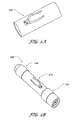
- FIG. 2A shows a first exemplary embodiment of a tail cap portion according to this invention
- FIG. 2B shows a second exemplary embodiment of a tail cap portion according to this invention
- FIG. 3A shows an exemplary body sleeve having an exemplary clip according to this invention
- FIG. 3B shows an exemplary embodiment of a modular illumination device utilizing a body sleeve having an exemplary clip according to this invention
- FIG. 4A shows an exemplary body sleeve having exemplary longitudinal surface preparations according to this invention
- FIG. 4B shows an exemplary embodiment of a modular illumination device utilizing a body sleeve having exemplary longitudinal surface preparations according to this invention
- FIG. 5A shows a perspective view of an exemplary body sleeve incorporating an exemplary rail mounting device according to this invention
- FIG. 5B shows a side view of a modified exemplary body sleeve incorporating an exemplary rail mounting device according to this invention
- FIG. 5C shows an exemplary embodiment of a modular illumination device utilizing a body sleeve incorporating an exemplary rail mounting device, the first exemplary embodiment of the tail cap portion, and the second exemplary embodiment of the head assembly according to this invention
- FIG. 5D shows an exemplary embodiment of a modular illumination device utilizing a body sleeve incorporating an exemplary rail mounting device and the second exemplary embodiment of the tail cap portion according to this invention
- FIG. 6A shows an exemplary body sleeve capable of accepting an exemplary clip and having recessed longitudinal surface preparations according to this invention
- FIG. 6B shows an exemplary body sleeve having an exemplary clip and protruding longitudinal surface preparations according to this invention
- FIG. 7A shows an exemplary body sleeve having substantially diamond shaped surface preparations according to this invention
- FIG. 7B shows an exemplary embodiment of a modular illumination device utilizing a body sleeve having substantially diamond shaped surface preparations and a second exemplary embodiment of a head assembly according to this invention
- FIG. 8A shows a plan view of an exemplary embodiment of a modular illumination device utilizing a body sleeve having an exemplary syringe style grip, the first exemplary embodiment of the tail cap portion, and the second exemplary embodiment of the head assembly according to this invention;
- FIG. 8B shows a perspective view of an exemplary embodiment of a modular illumination device utilizing a body sleeve having an exemplary syringe style grip, the first exemplary embodiment of the tail cap portion, and the second exemplary embodiment of the head assembly according to this invention;
- FIG. 9A shows an exemplary body sleeve having a body mounting and/or attachment portion according to this invention.
- FIG. 9B shows an exemplary embodiment of a modular illumination device utilizing a body sleeve having a body mounting and/or attachment portion and a second exemplary embodiment of a head assembly according to this invention
- FIG. 10A shows a first exemplary embodiment of a modular illumination device utilizing an attached or coupled filter according to this invention
- FIG. 10B shows a second exemplary embodiment of a modular illumination device utilizing an attached or coupled filter according to this invention
- FIG. 11A shows a side view of an inner body portion according to this invention
- FIG. 11B shows a bottom view of an inner body portion according to this invention.
- FIG. 11C shows a front perspective view of an inner body portion according to this invention.
- FIG. 11D shows a rear perspective view of an inner body portion according to this invention.
- FIG. 12 shows an exploded perspective view of a modular illumination device showing certain optional body sleeves according to this invention
- FIG. 13 shows a schematic diagram of an exemplary circuit for use as the light driver circuit according to this invention.
- FIG. 14 shows a schematic diagram of an exemplary circuit for use as the switching circuit according to this invention.
- FIGS. 15-19 show the exemplary body sleeve of FIGS. 9A and 9B utilized in connection with a body mounting and/or attachment portion according to this invention.
- module illumination device used to indicate the relative position of the systems, methods, and apparatuses of this invention. Therefore, the terms “modular illumination device”, “body sleeve”, “head assembly”, “tail cap portion”, “button assembly”, and “inner body portion” are not to be construed as limiting the systems, methods, and/or apparatuses of this invention.
- FIGS. 1-12 show various exemplary embodiments of a modular illumination device according to this invention.
- the modular illumination device 100 comprises at least some of an inner body portion 105 housing an electronics assembly 142 , a head assembly 120 , a tail cap portion 130 , and a body sleeve 110 .
- the head assembly 120 comprises at least some of a bezel 122 , a reflector 124 , a reflector isolator 124 ′, a glass or other lens 128 , and a retaining ring 125 .
- the components of the head assembly 120 are assembled as illustrated in FIG. 12 .
- One or more optional, appropriately sized O-rings are included between certain of the components of the head assembly 120 . In this manner, a watertight or water resistant seal may be created between the components of the head assembly 120 .
- one or more O-rings may be used as a shock isolator for the components of the head assembly 120 .
- the inner body portion 105 comprises a substantially hollow tube and is formed so as to house an electronics assembly 142 . It should be appreciated that the inner and/or outer shape of the inner body portion 105 may be generally oval, circular, triangular, square, pentangular, or any other desired shape.
- the cavity formed in the inner body portion 105 is shaped such that the electronics assembly 142 may be situated within the cavity formed in the inner body portion 105 .
- the components of the electronics assembly 142 are assembled as illustrated in FIGS. 11A-11D .
- the electronics assembly 142 optionally includes at least some of a pushbutton rotary encoder, a switching circuit, a battery tube or compartment formed so as to accommodate one or more batteries 160 , a negative battery contact, a positive battery contact, a light driver circuit, a heat sink, a light source 146 , and various programming pads 149 and/or contacts.
- the battery compartment provides a measure of shock isolation to the batteries 160 .
- the electronics assembly 142 includes one or more recessed channels.
- a flexible circuit may be disposed within the one or more recessed channels to electrically couple a switching circuit to the light driver circuit.
- the pushbutton rotary encoder is capable of being coupled to the tail cap button and of being depressed and/or rotated.
- the switching circuit which is electrically coupled to the pushbutton rotary encoder so as to receive input regarding depression and/or rotation of the pushbutton reverie encoder.
- the pushbutton rotary encoder is capable of being rotated continuously clockwise or counterclockwise, without a stop to limit the degree of rotation of the pushbutton rotary encoder.
- the pushbutton rotary encoder may include one or more stops that limit the degree of rotation of the pushbutton rotary encoder to a predetermined number of degrees.
- the pushbutton rotary encoder is capable of being smoothly rotated.
- the pushbutton rotary encoder may include certain detents that provide for incremental rotation of the pushbutton rotary encoder.
- the switching circuit is electrically coupled to the light driver circuit and the light driver circuit is electrically coupled to the light source 146 .
- the battery contacts are electrically coupled to one or more of the circuit boards to provide power from an appropriate battery or other voltage or current source to the electronics assembly 142 .
- the switching circuit and the light driver circuit may comprise separate and distinct components (as illustrated), the switching circuit, and the light driver circuit may comprise a single component capable of performing both functions. Furthermore, it should be appreciated that the functions of the switching circuit and/or the light driver circuit may be performed by either the switching circuit or the light driver circuit. Since the light driver circuit and the switching circuit work to provide a controller for the light source 146 the combination of the switching circuit and the light driver circuit is sometimes referred to herein as the controller.
- the controller (as embodied in the switching circuit, the light driver circuit, or a combination of both circuits) comprises an integrated circuit that functions as a solid-state control for the modular illumination device 100 .
- the controller comprises one or more high current MOSFETs that function as a microprocessor-controlled button. The controller may be pre-programmed at the chip production level.
- the controller may be programmed and/or reprogrammed based on the specific functions and/or modes desired by the user.
- the specific functions, channels, and/or modes of the modular illumination device 100 may be established and/or altered by a user.
- the controller may be programmed and/or reprogrammed via a direct or indirect linked connection to a programming and/or reprogramming device.
- a programming and/or reprogramming device For example, one or more plugs, contact points, programming pads, and/or contacts may be electrically coupled to the controller, such that the controller may be coupled, via one or more corresponding plugs, contact points, programming pads, and/or contacts, to a programming and/or reprogramming device.
- the linked connection can be any known or later developed device or system for connecting the controller to a programming and/or reprogramming device, including a direct wired connection, a connection over a cellular telephone network, a very high frequency (VHF) connection, an ultra high frequency (UHF) connection, a radio frequency (RF) connection, a satellite connection, or the like.
- VHF very high frequency
- UHF ultra high frequency
- RF radio frequency
- the linked connection can be any known or later developed connection system or structure usable to connect a programming and/or reprogramming device to the controller, including both wired and wireless connections.
- the controller may, for example, be programmed to initially illuminate the light source 146 at a particular light level.
- the controller may also be programmed to initially illuminate the light source 146 in an on/off, or strobe, mode.
- the controller may strobe the light source 146 at a rate of greater than 0 to 60 Hz.
- the controller may strobe the light source 146 at a rate of greater than 0 to 30 Hz.
- the controller may strobe the light source 146 at a rate of about 8 to 20 Hz.
- the particular strobe rate may be predetermined and fixed or may be adjustable.
- a particular strobe rate may be chosen based on a desired effect of the strobed light on an individual. For example, a strobing rate may be chosen, which effectively masks tactical movement but is not in a realm that can trigger adverse effects in an individual.
- the controller may be programmed to illuminate the light source 146 in a signaling mode. In the signaling mode, the controller controls the light source 146 to emit either visible or non-visible light in a predetermined on/off pattern.
- the signaling pattern may be a standard, preprogrammed pattern, such as, for example, a Morse code pattern. Alternatively, the signaling pattern may be a specific, user-defined pattern.
- Visible light and/or non-visible light may be used to provide a signaling pattern.
- a visible light signaling pattern may be used in a non-covert emergency situation to facilitate the location and/or identification of an individual.
- a non-visible light signaling pattern may be used to facilitate the location and/or identification of an individual in need of rescue in a covert situation.
- light signaling patterns may comprise visible light patterns, non-visible light patterns, or a combination of visible and non-visible light patterns.
- the light source 146 comprises a LED.
- the light source 146 may comprise an incandescent, infrared, laser, or other known or later developed visible or non-visible wavelength illumination device.
- the light source 146 may comprise a combination of one or more LEDs, incandescent, infrared, laser, or other known or later developed visible or non-visible wavelength illumination devices.
- additional materials such as, for example, gaskets or additional O-rings (not shown), may be included between various components of the electronics assembly 142 to provide a level of shock isolation to the components of the electronics assembly 142 .
- the inner body portion 105 comprises and elongate portion having a first end and a second end.
- each end of the inner body portion 105 includes an external (as illustrated) or internal threaded portion.
- the threaded portion or portions of the inner body portion 105 are formed so as to correspond to mating internal or external threads of the head assembly 120 and the tail cap portion 130 .
- the inner body portion 105 comprises an inner cavity that is capable of accepting the electronics assembly 142 , while the exterior of the inner body portion 105 is formed so as to fit within a body sleeve 110 .
- the inner body portion 105 and the body sleeve 110 may include cooperating alignment means.
- the alignment means operate such that, when the body sleeve 110 is fitted over the inner body portion 105 , the inner body portion 105 is properly indexed to the body sleeve 110 .
- the alignment means may comprise an anti-rotation pin extending from the interior of the body sleeve 110 and positioned so as to engage a corresponding alignment groove formed in the exterior of the inner body portion 105 .
- the alignment means may comprise an alignment groove formed in the interior of the body sleeve 110 and positioned so as to engage a corresponding anti-rotation pin extending from the exterior of the inner body portion 105 .
- the alignment means comprise a notch formed in either the inner body portion 105 or the body sleeve 110 and positioned so as to engage a corresponding mating block formed in either the body sleeve 110 or the inner body portion 105 , respectively.
- the inner body portion 105 may have an exterior shape or one or more surface preparations, grooves, or the like, which correspond to an interior shape or other interior surface preparations, grooves, or the like of the interior of the body sleeve 110 such that, once engaged, the body sleeve 110 does not rotate with respect to the inner body portion 105 .
- the exterior of the body sleeve 110 may be formed so as to include various surface preparations, textured portions, protrusions, intentions, grooves, flats, mounting assemblies, clips, rails, grips, anti-rotation features, and the like.
- at least a portion of the outer diameter of the body sleeve 110 is such that the modular illumination device 100 may be mounted on a variety of devices using known ring mounts.
- At least a portion of the body sleeve 110 may include a groove or flat portion that provides an anti-rotation feature to the modular illumination device 100 when held within a ring mount.
- the exterior of the body sleeve may take any desired form or shape based upon the ornamental appearance, functionality, compatibility, and/or interactivity of the body sleeve, and ultimately the modular illumination device.
- FIG. 3A shows an exemplary body sleeve 210 having an exemplary clip according to this invention.
- FIG. 3B shows an exemplary embodiment of a modular illumination device 200 utilizing the body sleeve 210 having the exemplary clip. It should be understood that while the body sleeve 210 is shown having a relatively smooth exterior surface, the body sleeve 210 may incorporate any exterior shape and/or any desired surface preparations.
- the clip is illustrated as having a generally wishbone shape, a clip having any size shape or configuration may be utilized with the body sleeve 210 .
- the clip is illustrated as being coupled, via screws, to the body sleeve 210 , it should be appreciated that the clip may be otherwise affixed, attached, or coupled to the body sleeve 210 were may be formed as an integral part of the body sleeve 210 .
- FIG. 4A shows an exemplary body sleeve 310 having exemplary longitudinal surface preparations according to this invention
- FIG. 4B shows an exemplary embodiment of a modular illumination device 300 utilizing the body sleeve 310 .
- FIG. 5A shows a perspective view of an exemplary body sleeve 410 incorporating an exemplary rail mounting device according to this invention.
- the rail mounting device comprises the offset accessory mount and/or accessory mounting clamp as shown and described in co-pending U.S. patent application Ser. No. 11/985,659, Filed Nov. 16, 2007, entitled Offset Accessory Mount, the entire disclosure of which is incorporated herein by reference.
- the body sleeve 410 may comprise a is relatively smooth exterior surface.
- the body sleeve 410 ′ may incorporate certain surface preparations, such as, for example, recesses, or grooves.
- the body sleeve 410 ′ (wherein the body sleeve 410 ′ includes a series of recesses or grooves) is used in conjunction with a tail cap portion 130 ′ (wherein the tail cap portion 130 ′ includes knurled portions around the outer circumference and a shortened collar portion) and a head assembly 220 (wherein the head assembly 220 includes knurled portions around the outer circumference and a scalloped front edge).
- the body sleeve 410 (wherein the body sleeve 410 is relatively smooth) is used in conjunction with a tail cap portion 130 (wherein the tail cap portion 130 includes a relatively smooth outer surface and an extended collar portion) and a head assembly 120 (wherein the head assembly 120 includes a relatively smooth outer surface and a front portion having a reduced diameter as compared to a rear portion, resulting in a shoulder between the front portion and the rear portion).
- FIG. 6A shows an exemplary body sleeve for if for capable of accepting an exemplary clip and having recessed longitudinal surface preparations.
- FIG. 6B shows an exemplary body sleeve 610 ′ having an exemplary clip and protruding longitudinal surface preparations.
- FIG. 7A shows an exemplary body sleeve 710 having substantially diamond shaped surface preparations
- FIG. 7B shows an exemplary embodiment of a modular illumination device 700 utilizing the body sleeve 710 having substantially diamond shaped surface preparations, a head assembly 220 , and a tail cap portion 130 ′.
- FIGS. 8A and 8B show a plan view and a perspective view, respectively, of an exemplary embodiment of a modular illumination device 800 utilizing a body sleeve 810 having an exemplary syringe style grip, the tail cap portion 130 ′, and the head assembly 220 according to this invention.
- the body sleeve 810 includes a plurality of lugs 812 that extend substantially radially from the body sleeve 810 .
- the lugs provide an anti-roll featured to the modular illumination device 100 .
- the lugs 812 may be contoured so as to assist in certain specialized grip techniques when employed with a firearm or be used as a defensive tool or a tool in personal control techniques. Additionally, the lugs 812 may include one or more holes or other attachment means such that a lanyard or other device may be attached to the body sleeve 810 . It should be understood that while the body sleeve 810 is shown as having four lugs 812 , the number and shape of the lugs is a design choice based on the desired functionality of the lugs.
- FIG. 9A shows an exemplary body sleeve 910 having a body mounting and/or attachment portion
- FIG. 9B shows an exemplary embodiment of a modular illumination device 900 utilizing the body sleeve 910 .
- FIGS. 15-19 show the exemplary body sleeve of FIGS. 9A and 9B utilized in connection with a body mounting and/or attachment portion according to this invention. As illustrated, certain retractable locking devices protrude into the body mounting and/or attachment portion of the body sleeve 910 to maintain it in position.
- the head assembly 120 and more specifically, the bezel 122 can be shaped so as to accept a filter assembly 1010 or 1010 ′.
- the filter assembly 1010 or 1010 ′ is sized so as to be fractionally maintained in position on the head assembly 120 .
- the filter assembly may be threadedly or otherwise coupled are attached to the head assembly 120 .
- the filter assemblies 1010 and 1010 ′ are illustrated as having lenses or filters that are hingedly coupled to the filter assemblies 1010 and 1010 ′, it should be appreciated that the lenses or filters may be permanently attached to the filter assemblies 1010 and 1010 ′.
- At least a portion of the bezel 122 has a 11 ⁇ 4 inch outer diameter.
- the bezel 122 may include a scalloped surface or end portion.
- the tail cap portion 130 comprises at least some of a collar 132 and a button 136 .
- the collar 132 is internally or externally threaded such that the tail cap portion 130 may be threadedly attached to corresponding internal or external threads at an end of the inner body portion 105 .
- the tail cap button 136 interacts with the pushbutton rotary encoder of the electronics assembly 142 .
- the pushbutton rotary encoder is depressed.
- the pushbutton rotary encoder is rotated.
- FIG. 2B shows a second exemplary embodiment of a tail cap portion 130 ′, according to this invention.
- the button 136 (as illustrated in FIG. 2A ) is replaced by an optional tape switch, which extends from the collar 132 of the tail cap portion 130 ′.
- the tape switch includes a pressure-activated switch, or pressure pad 136 ′ that can be depressed to activate the features of the modular illumination device 100 , as described herein.
- the pressure pad 136 ′ includes a tape switch coupler that makes appropriate contact with the controller such that depression of the pressure pad 136 ′ can act to activate the controller.
- any known or later developed pressure pad may be used as the pressure pad 136 ′.
- the size, shape, and orientation of the pressure pad 136 ′ is a design choice based upon the desired functionality of the tape switch.
- one or more of the inner body portion 105 , the head assembly 120 , and/or the tail cap portion 130 may include cooperating alignment means.
- the alignment means operate such that, when the head assembly 120 or the tail cap portion 130 is coupled to the inner body portion 105 , the head assembly 120 or the tail cap portion 130 is properly indexed to the inner body portion 105 .
- the alignment means comprise an anti-rotation pin extending from the interior of the inner body portion 105 and positioned so as to engage a corresponding alignment groove formed in the interior of the inner body portion 105 or the head assembly 120 , respectively.
- the alignment means may comprise an alignment groove formed in the exterior of the inner body portion 105 and positioned so as to engage a corresponding anti-rotation pin extending from the interior of the inner body portion 105 or the head assembly 120 , respectively.
- the alignment means comprise a notch formed in either the inner body portion 105 , the head assembly 120 , or the tail cap portion 130 and positioned so as to engage a corresponding mating block formed in either the inner body portion 105 , the head assembly 120 , or the tail cap portion 130 , respectively.
- an inner threaded portion of the head assembly 120 or the tail cap portion 130 corresponds to an outer threaded portion of the inner body portion 105 .
- an inner threaded portion of the inner body portion 105 corresponds to an outer threaded portion of the head assembly 120 or the tail cap portion 130 .
- the tail cap portion 130 or the head assembly 120 may be removably attached to the inner body portion 105 .
- an O-ring (not shown) may be included in an appropriately sized groove in the outer surface of the inner body portion 105 to provide a water resistant or shock absorbent seal between the inner body portion 105 and the head assembly 120 or the tail cap portion 130 .
- At least some of the inner body portion 105 , the head assembly 120 , or the tail cap portion 130 may be formed of aluminum, a plastic, such as, for example, a thermoplastic or a polypropylene plastic, or stainless steel.
- Alternate materials of construction may include one or more of the following: steel, aluminum, titanium, and/or other ferros or non-ferros metals, as well as various alloys and composites thereof, glass-hardened polymers, polymer or fiber reinforced metals, carbon fiber or glass fiber composites, thermoset or thermoplastic resins, chopped glass or carbon fibers used for injection molding compounds, laminate glass or carbon fiber, epoxy laminates, woven glass fiber laminates, impregnate fibers, polyester resins, epoxy resins, phenolic resins, polyimide resins, cyanate resins, high-strength plastics, polymers, polymeric composites, thermoplastics, polypropylene, nylon, glass, or polymer fiber reinforced plastics, thermoform and/or thermoset sheet materials, and/or various combinations of the foregoing.
- One or more optional, appropriately sized O-rings may be included between the head assembly 120 and the inner body portion 105 and/or between a tail cap assembly 130 and the inner body portion 105 .
- the head assembly 120 is generally removably attached are coupled to the inner body portion 105 , in various exemplary embodiments, the head assembly 120 may be permanently attached or coupled to the inner body portion 105 . Alternatively, the head assembly 120 may be formed as an integral part of the inner body portion 105 .
- the tail cap assembly 130 is generally removably attached are coupled to the inner body portion 105 , in various exemplary embodiments, the tail cap assembly 130 may be permanently attached or coupled to the inner body portion 105 . Alternatively, the tail cap assembly 130 may be formed as an integral part of the inner body portion 105 .
- an actuator is moved from a spring biased, or first position within the tail cap assembly 130 to a depressed, or second, position within the tail cap assembly 130 .
- a signal is sent to the controller.
- the controller determines the output function for the light source 146 that is represented by the number of times and/or duration of time that the button 136 is depressed and activates the light source 146 appropriately.
- the controller When the button 136 is rotated the controller will control the light source 146 to brighten or dim (using, for example, pulse width modulation) based on the rotation of the button 136 . For example, if the button 136 is rotated clockwise, the light source 146 may be controlled to brighten and if the button 136 is rotated counterclockwise, the light source 146 may be controlled to dim. Alternatively, it may be established that when the button 136 is rotated clockwise, the light source 146 may be controlled to dim and if the button 136 is rotated counterclockwise, the light source 146 may be controlled to brighten.
- each light activating function is defined by the number of times and/or duration of time that the button 136 is depressed, while the intensity of the light source 146 is controlled by the axial position of the button 136 .
- the controller is capable of controlling the light source 146 to produce three different light emitting functions.
- the three light emitting functions include a constant on mode, a momentary on mode, and a strobe mode.
- the light source 146 may be controlled to illuminate at maximum power then off at a rate of about 8-20 Hz. In various exemplary embodiments, if the button 136 is rotated in the strobe mode, the rate of strobe can be altered.
- the light source 146 can be illuminated at maximum power or adjusted to a lower power setting, allowing use of the light at less than full brightness or at the last saved level.
- manual programming of the light can be achieved by depressing the button 136 for a determined period of time, such as, for example, 10 seconds. After the determined very time has been achieved, the light source 146 blinks twice. After the light source blanks twice, the button 136 must be depressed for another determined period time, such as, for example, 10 seconds. Once the second predetermined period time has run, the light source 146 in blinks twice and advances to the next preprogrammed mode. In this manner, the light is capable of cycling through predetermined levels such as full brightness, full dimm, and last saved level.
- the light may be controlled to dim. Over, for example, approximately 5 seconds, the light will dim from maximum brightness to minimum brightness. If the button 136 is released at any point during the dimming cycle, the light output from the light source 146 will remain at the brightness/power output level the light source 146 was at when the button 136 was released.
- the light begins to brighten from the brightness level the light source 146 was at when the button 136 was initially released. Over a period of time, the light will brighten to maximum brightness. If the button 136 is released at any point during the brightening cycle, the light output from the light source 146 will remain at the brightness/power output level the light source 146 was at when the button 136 was released.
- the brightness level of the light source 146 will continue to cycle from a maximum brightness to a minimum brightness, or vice versa.
- the light source 146 is turned off.
- the button 136 may also be used to activate a lockout mode.
- the purpose of the lockout mode is to prevent the light from being illuminated or extinguished unintentionally. Activating the lockout mode is achieved by partially depressing the button 136 (approximately 1 ⁇ 3 of the full travel) and turning the button 136 in a predetermined (clockwise or counter-clockwise) direction. In the lockout mode, the button 136 remains partially depressed serving as visual indication that the tail cap portion 130 is in the lockout mode. In this channel, the button 136 is prevented from being depressed by an internal stop.
- the button 136 When the button 136 is rotated to the lockout mode while the light source 146 is off, the button 136 is prevented from being depressed, and the light source 146 is effectively prevented from being activated.
- the button 136 when the button 136 is rotated to the lockout mode while the light source 146 is illuminated, the button 136 is prevented from being depressed, and the light source 146 is effectively prevented from being extinguished.
- the button 136 is merely rotated in a rotational direction opposite the direction used to engage the lockout mode. Once the button 136 is rotated out of the lockout mode, the button 136 may be freely depressed. In various exemplary embodiments, the rotational force necessary to rotate the button 136 out of the lockout mode is greater than the rotational force necessary to accomplish normal rotation of the button 136 .
- the lockout mode may be achieved by depressing the button 136 and rotating the button 180°. This places the light in lockout mode. While and lockout mode, the controller continues to poll the switch to determine whether the button 136 has been depressed.
- the light source 146 illuminates twice to confirm that the lockout mode has been achieved. Then, to move the light out of the lockout mode, the button 136 is again depressed and rotated 180°.
- the 180° rotation can be in either direction as the controller, during lockout mode, monitors the number of degrees that the button is rotated and not the direction.
- the controller may optionally control the light source 146 to flash off for a brief period of time (approximately microseconds) and then turn back on at the desired power. This may occur approximately every 10 seconds for a predetermined period of time.
- the controller may optionally control the light source 146 to operate at a lower power/brightness mode in an effort to extend the amount of time the light source 146 can remain on.
- the controller monitors the temperature of the light source 146 and automatically reduces the output of the light source 146 (for example, through pulse width modulation) in an effort to keep the light source 146 from exceeding a predetermined temperature level. If temperature of the light source 146 exceeds a predetermined threshold, the controller may turn the light source 146 off until the temperature of the light source 146 falls below a predetermined threshold.
- FIG. 13 shows a schematic diagram of an exemplary circuit for use as the light driver circuit according to this invention.
- FIG. 14 shows a schematic diagram of an exemplary circuit for use as the switching circuit according to this invention.
- a capacitor is placed between the LED and the power supply.
- the capacitor is designed so as to maintain sufficient current to keep the controller active if electrical connection between the power supply and the controller is momentarily lost. In this manner, the affects of jarring and are recoil on the light are reduced.
Abstract
Description
Claims (26)
Priority Applications (1)
| Application Number | Priority Date | Filing Date | Title |
|---|---|---|---|
| US12/735,602 US9217558B2 (en) | 2008-02-02 | 2009-02-02 | Modular illumination device |
Applications Claiming Priority (3)
| Application Number | Priority Date | Filing Date | Title |
|---|---|---|---|
| US6323908P | 2008-02-02 | 2008-02-02 | |
| US12/735,602 US9217558B2 (en) | 2008-02-02 | 2009-02-02 | Modular illumination device |
| PCT/US2009/000659 WO2009097154A1 (en) | 2008-02-02 | 2009-02-02 | Modular illumination device |
Publications (2)
| Publication Number | Publication Date |
|---|---|
| US20110164411A1 US20110164411A1 (en) | 2011-07-07 |
| US9217558B2 true US9217558B2 (en) | 2015-12-22 |
Family
ID=40913161
Family Applications (1)
| Application Number | Title | Priority Date | Filing Date |
|---|---|---|---|
| US12/735,602 Expired - Fee Related US9217558B2 (en) | 2008-02-02 | 2009-02-02 | Modular illumination device |
Country Status (2)
| Country | Link |
|---|---|
| US (1) | US9217558B2 (en) |
| WO (1) | WO2009097154A1 (en) |
Cited By (5)
| Publication number | Priority date | Publication date | Assignee | Title |
|---|---|---|---|---|
| US20160000308A1 (en) * | 2013-02-08 | 2016-01-07 | Foward Science Technologies Llc | Oral examination |
| US20180038577A1 (en) * | 2016-08-08 | 2018-02-08 | Andrew Paul Jones | Multi-color hunting spotlight |
| US11457820B2 (en) | 2013-02-08 | 2022-10-04 | Forward Science Technologies, LLC | Oral examination |
| US11761593B2 (en) | 2021-09-13 | 2023-09-19 | Techtronic Cordless Gp | Portable lighting apparatus |
| USD1017756S1 (en) * | 2018-02-23 | 2024-03-12 | Federal Cartridge Company | Shotgun wad |
Families Citing this family (15)
| Publication number | Priority date | Publication date | Assignee | Title |
|---|---|---|---|---|
| SK5457Y1 (en) * | 2008-10-21 | 2010-06-07 | Yalong Trade S R O | Nasal applicator for intranasal laser irradiation of blood |
| DE102011103653A1 (en) | 2011-06-08 | 2012-12-13 | Zweibrüder Optoelectronics Gmbh & Co. Kg | Cylindrical flashlight with roll-off protection |
| US9435522B2 (en) * | 2012-05-17 | 2016-09-06 | Emissive Energy Corp. | Pistol mounted light and operation thereof |
| US10345680B2 (en) * | 2013-05-21 | 2019-07-09 | Forward Science Technologies, LLC | Optical filtering attachment |
| USD780362S1 (en) | 2013-12-09 | 2017-02-28 | Kenall Manufacturing Company | Lighting fixture |
| US9562627B2 (en) | 2013-12-09 | 2017-02-07 | Kenall Manufacturing Company | Luminaire and improved lighting system |
| USD732225S1 (en) | 2013-12-09 | 2015-06-16 | Kenall Manufacturing Company | Lighting fixture |
| US8882532B1 (en) | 2013-12-09 | 2014-11-11 | Kenall Manufacturing Company | Driver box for an improved lighting system |
| US9310066B2 (en) | 2013-12-09 | 2016-04-12 | Kenall Manufacturing Company | Electronic component for an improved lighting system |
| USD742581S1 (en) | 2013-12-09 | 2015-11-03 | Kenall Manufacturing Company | Driver housing |
| US11162647B2 (en) * | 2018-07-10 | 2021-11-02 | Simple Products Corporation | Flashlight with overmolded grip and methods of manufacture |
| USD928958S1 (en) | 2018-11-15 | 2021-08-24 | Forward Science Technologies, LLC | Skin cancer screening device |
| USD888957S1 (en) | 2018-11-15 | 2020-06-30 | Forward Science Technologies, LLC | Skin cancer screening device |
| CN111306480B (en) * | 2020-03-30 | 2023-10-31 | 青岛亿联客信息技术有限公司 | Lamp set |
| USD1007727S1 (en) * | 2021-06-18 | 2023-12-12 | Shanghai Hoto Technology Co., Ltd. | Flashlight |
Citations (11)
| Publication number | Priority date | Publication date | Assignee | Title |
|---|---|---|---|---|
| JP2000021202A (en) * | 1998-07-01 | 2000-01-21 | Toshiba Battery Co Ltd | Standing permanent light |
| US6079847A (en) * | 1998-10-01 | 2000-06-27 | Nelson; Chad Carl | Programmable signal light |
| JP2000326789A (en) * | 1999-03-15 | 2000-11-28 | Kyoei Sangyo Kk | Decorative lamp device for automobile |
| KR20030060044A (en) * | 2002-01-03 | 2003-07-12 | 이현주 | signal apparatus having vibrate switch |
| US20040095759A1 (en) * | 2000-05-31 | 2004-05-20 | Koch Greg W. | Flashlight and flashlight electrical connectors |
| US20050237737A1 (en) * | 2003-12-09 | 2005-10-27 | Surefire Llc | Flashlight with detented rotary control |
| US20050265014A1 (en) * | 2004-05-25 | 2005-12-01 | Nikon Corporation | Illuminating device for photographing and camera |
| US7208932B1 (en) * | 2002-11-27 | 2007-04-24 | Chun James K | Voltage detector |
| US20070247839A1 (en) * | 2003-12-09 | 2007-10-25 | Matthews John W | Flashlight with selectable output level switching |
| US20100090613A1 (en) * | 2007-06-20 | 2010-04-15 | Eveready Battery Company, Inc. | Lighting Device Having Light Intensity Control |
| US8197085B2 (en) * | 2007-06-20 | 2012-06-12 | Eveready Battery Company, Inc. | Portable lighting device having user selectable light control |
Family Cites Families (3)
| Publication number | Priority date | Publication date | Assignee | Title |
|---|---|---|---|---|
| US6283609B1 (en) * | 1996-10-28 | 2001-09-04 | Armament Systems And Procedures, Inc. | Tactical flashlight |
| TWM246525U (en) * | 2003-08-25 | 2004-10-11 | Han-Chuan Lin | Portable LED flash light |
| US7281815B1 (en) * | 2004-10-19 | 2007-10-16 | Blackhawk Industries Product Group Unlimited Llc | Lighting device having a multi-position switch assembly |
-
2009
- 2009-02-02 US US12/735,602 patent/US9217558B2/en not_active Expired - Fee Related
- 2009-02-02 WO PCT/US2009/000659 patent/WO2009097154A1/en active Application Filing
Patent Citations (11)
| Publication number | Priority date | Publication date | Assignee | Title |
|---|---|---|---|---|
| JP2000021202A (en) * | 1998-07-01 | 2000-01-21 | Toshiba Battery Co Ltd | Standing permanent light |
| US6079847A (en) * | 1998-10-01 | 2000-06-27 | Nelson; Chad Carl | Programmable signal light |
| JP2000326789A (en) * | 1999-03-15 | 2000-11-28 | Kyoei Sangyo Kk | Decorative lamp device for automobile |
| US20040095759A1 (en) * | 2000-05-31 | 2004-05-20 | Koch Greg W. | Flashlight and flashlight electrical connectors |
| KR20030060044A (en) * | 2002-01-03 | 2003-07-12 | 이현주 | signal apparatus having vibrate switch |
| US7208932B1 (en) * | 2002-11-27 | 2007-04-24 | Chun James K | Voltage detector |
| US20050237737A1 (en) * | 2003-12-09 | 2005-10-27 | Surefire Llc | Flashlight with detented rotary control |
| US20070247839A1 (en) * | 2003-12-09 | 2007-10-25 | Matthews John W | Flashlight with selectable output level switching |
| US20050265014A1 (en) * | 2004-05-25 | 2005-12-01 | Nikon Corporation | Illuminating device for photographing and camera |
| US20100090613A1 (en) * | 2007-06-20 | 2010-04-15 | Eveready Battery Company, Inc. | Lighting Device Having Light Intensity Control |
| US8197085B2 (en) * | 2007-06-20 | 2012-06-12 | Eveready Battery Company, Inc. | Portable lighting device having user selectable light control |
Cited By (10)
| Publication number | Priority date | Publication date | Assignee | Title |
|---|---|---|---|---|
| US20160000308A1 (en) * | 2013-02-08 | 2016-01-07 | Foward Science Technologies Llc | Oral examination |
| US10413191B2 (en) * | 2013-02-08 | 2019-09-17 | Forward Science Technologies, LLC | Oral examination |
| US11457820B2 (en) | 2013-02-08 | 2022-10-04 | Forward Science Technologies, LLC | Oral examination |
| US20180038577A1 (en) * | 2016-08-08 | 2018-02-08 | Andrew Paul Jones | Multi-color hunting spotlight |
| US9951928B2 (en) * | 2016-08-08 | 2018-04-24 | Andrew Paul Jones | Multi-color hunting spotlight |
| US20180274759A1 (en) * | 2016-08-08 | 2018-09-27 | Andrew Paul Jones | Multi-color hunting spotlight |
| US10208924B2 (en) * | 2016-08-08 | 2019-02-19 | Allpredatorcalls.Com, Inc. | Multi-color hunting spotlight |
| US11028998B2 (en) * | 2016-08-08 | 2021-06-08 | Allpredatorcalls.Com, Inc. | Multi-color hunting spotlight |
| USD1017756S1 (en) * | 2018-02-23 | 2024-03-12 | Federal Cartridge Company | Shotgun wad |
| US11761593B2 (en) | 2021-09-13 | 2023-09-19 | Techtronic Cordless Gp | Portable lighting apparatus |
Also Published As
| Publication number | Publication date |
|---|---|
| WO2009097154A1 (en) | 2009-08-06 |
| US20110164411A1 (en) | 2011-07-07 |
Similar Documents
| Publication | Publication Date | Title |
|---|---|---|
| US9217558B2 (en) | Modular illumination device | |
| US7281815B1 (en) | Lighting device having a multi-position switch assembly | |
| US7802898B1 (en) | Lightning device | |
| US8469540B1 (en) | Contact switch for a lighting device | |
| US10208931B2 (en) | Weapon mounted light and operation thereof | |
| US10208936B2 (en) | Multi-mode portable lighting device | |
| US7954971B1 (en) | Offset mountable light accessory | |
| US7784963B2 (en) | Multi-function flashlight | |
| US7517109B2 (en) | Flashlight with rotary head brightness control and detachable tailcap mount | |
| US8376574B2 (en) | Multi-spectrum lighting device having a plurality of illumination modes | |
| US8371729B2 (en) | Light with keying arrangement mountable on a mounting rail | |
| US9408262B2 (en) | Multi-mode portable lighting device | |
| US8132355B1 (en) | Offset accessory mount and mounting system | |
| US8287157B2 (en) | Light with removable head and cover | |
| US9991062B2 (en) | Electrical switch device | |
| EP2251586A2 (en) | Lighting device with removable cradle | |
| US20110012535A1 (en) | Portable lighting devices | |
| US10393477B1 (en) | Retention holster for a firearm having an offset mounted accessory | |
| US7922350B1 (en) | Tactical illuminator | |
| EP2180236A2 (en) | Flashlight with i/o bus bar | |
| EP2085682A2 (en) | Multi-function flashlight | |
| EP2180237A2 (en) | Method of operating a multi-function flashlight | |
| EP2180239A2 (en) | Control system for a multi-function flashlight | |
| EP2180238A2 (en) | Head assembly for a multi-function flashlight | |
| AU2012208314A1 (en) | Multi-mode portable lighting device |
Legal Events
| Date | Code | Title | Description |
|---|---|---|---|
| AS | Assignment |
Owner name: BLACKHAWK INDUSTRIES PRODUCT GROUP UNLIMITED LLC, Free format text: ASSIGNMENT OF ASSIGNORS INTEREST;ASSIGNORS:SPARING, KURTIS J.;KINCAID, ROBERT A.;TODD, BIRTEN L.;AND OTHERS;SIGNING DATES FROM 20110123 TO 20110204;REEL/FRAME:026329/0565 |
|
| AS | Assignment |
Owner name: ALLIANT TECHSYSTEMS INC., MINNESOTA Free format text: NUNC PRO TUNC ASSIGNMENT;ASSIGNOR:BLACKHAWK INDUSTRIES PRODUCT GROUP UNLIMITED LLC;REEL/FRAME:027446/0227 Effective date: 20100901 |
|
| AS | Assignment |
Owner name: BANK OF AMERICA, N.A., CALIFORNIA Free format text: SECURITY AGREEMENT;ASSIGNORS:ALLIANT TECHSYSTEMS INC.;CALIBER COMPANY;EAGLE INDUSTRIES UNLIMITED, INC.;AND OTHERS;REEL/FRAME:031731/0281 Effective date: 20131101 |
|
| AS | Assignment |
Owner name: EAGLE INDUSTRIES UNLIMITED, INC., VIRGINIA Free format text: INTELLECTUAL PROPERTY SECURITY AGREEMENT RELEASE;ASSIGNOR:BANK OF AMERICA, N.A.;REEL/FRAME:034954/0732 Effective date: 20150209 Owner name: CALIBER COMPANY, MINNESOTA Free format text: INTELLECTUAL PROPERTY SECURITY AGREEMENT RELEASE;ASSIGNOR:BANK OF AMERICA, N.A.;REEL/FRAME:034954/0732 Effective date: 20150209 Owner name: SAVAGE RANGE SYSTEMS, INC., MASSACHUSETTS Free format text: INTELLECTUAL PROPERTY SECURITY AGREEMENT RELEASE;ASSIGNOR:BANK OF AMERICA, N.A.;REEL/FRAME:034954/0732 Effective date: 20150209 Owner name: FEDERAL CARTRIDGE COMPANY, MINNESOTA Free format text: INTELLECTUAL PROPERTY SECURITY AGREEMENT RELEASE;ASSIGNOR:BANK OF AMERICA, N.A.;REEL/FRAME:034954/0732 Effective date: 20150209 Owner name: SAVAGE ARMS, INC., MASSACHUSETTS Free format text: INTELLECTUAL PROPERTY SECURITY AGREEMENT RELEASE;ASSIGNOR:BANK OF AMERICA, N.A.;REEL/FRAME:034954/0732 Effective date: 20150209 Owner name: SAVAGE SPORTS CORPORATION, MINNESOTA Free format text: INTELLECTUAL PROPERTY SECURITY AGREEMENT RELEASE;ASSIGNOR:BANK OF AMERICA, N.A.;REEL/FRAME:034954/0732 Effective date: 20150209 Owner name: ALLIANT TECHSYSTEMS INC., MINNESOTA Free format text: INTELLECTUAL PROPERTY SECURITY AGREEMENT RELEASE;ASSIGNOR:BANK OF AMERICA, N.A.;REEL/FRAME:034954/0732 Effective date: 20150209 |
|
| AS | Assignment |
Owner name: BANK OF AMERICA, N.A., CALIFORNIA Free format text: SECURITY INTEREST;ASSIGNORS:VISTA OUTDOOR INC.;BEE STINGER, LLC;BOLLE AMERICA, INC.;AND OTHERS;REEL/FRAME:035223/0808 Effective date: 20150209 |
|
| AS | Assignment |
Owner name: VISTA OUTDOOR OPERATIONS LLC, UTAH Free format text: ASSIGNMENT OF ASSIGNORS INTEREST;ASSIGNOR:ALLIANT TECHSYSTEMS INC.;REEL/FRAME:035455/0404 Effective date: 20150206 |
|
| STCF | Information on status: patent grant |
Free format text: PATENTED CASE |
|
| AS | Assignment |
Owner name: ALLIANT TECHSYSTEMS INC., MINNESOTA Free format text: NUNC PRO TUNC ASSIGNMENT;ASSIGNOR:BLACKHAWK INDUSTRIES PRODUCT GROUP UNLIMITED LLC;REEL/FRAME:037227/0658 Effective date: 20100901 Owner name: BLACKHAWK INDUSTRIES PRODUCT GROUP UNLIMITED LLC, Free format text: ASSIGNMENT OF ASSIGNORS INTEREST;ASSIGNORS:SPARING, KURTIS J.;KINCAID, ROBERT A.;TODD, BIRTEN L.;AND OTHERS;SIGNING DATES FROM 20110123 TO 20110204;REEL/FRAME:037227/0606 |
|
| AS | Assignment |
Owner name: BANK OF AMERICA, N.A., CALIFORNIA Free format text: SECURITY INTEREST;ASSIGNORS:VISTA OUTDOOR INC.;VISTA COMMERCIAL AMMUNITION COMPANY INC.;VISTA COMMERCIAL AMMUNITION HOLDINGS COMPANY INC.;AND OTHERS;REEL/FRAME:038412/0934 Effective date: 20160401 |
|
| AS | Assignment |
Owner name: WELLS FARGO BANK, NATIONAL ASSOCIATION, AS ADMINISTRATIVE AGENT, CALIFORNIA Free format text: TERM LOAN INTELLECTUAL PROPERTY SECURITY AGREEMENT;ASSIGNORS:BEE STINGER, LLC;BELL SPORTS, INC.;BUSHNELL HOLDINGS, INC.;AND OTHERS;REEL/FRAME:047602/0001 Effective date: 20181119 Owner name: WELLS FARGO BANK, NATIONAL ASSOCIATION, AS ADMINIS Free format text: TERM LOAN INTELLECTUAL PROPERTY SECURITY AGREEMENT;ASSIGNORS:BEE STINGER, LLC;BELL SPORTS, INC.;BUSHNELL HOLDINGS, INC.;AND OTHERS;REEL/FRAME:047602/0001 Effective date: 20181119 |
|
| AS | Assignment |
Owner name: WELLS FARGO BANK, NATIONAL ASSOCIATION, AS ADMINISTRATIVE AGENT, CALIFORNIA Free format text: ABL INTELLECTUAL PROPERTY SECURITY AGREEMENT;ASSIGNORS:BEE STINGER, LLC;BELL SPORTS, INC.;BUSHNELL HOLDINGS, INC.;AND OTHERS;REEL/FRAME:047609/0001 Effective date: 20181119 Owner name: WELLS FARGO BANK, NATIONAL ASSOCIATION, AS ADMINIS Free format text: ABL INTELLECTUAL PROPERTY SECURITY AGREEMENT;ASSIGNORS:BEE STINGER, LLC;BELL SPORTS, INC.;BUSHNELL HOLDINGS, INC.;AND OTHERS;REEL/FRAME:047609/0001 Effective date: 20181119 |
|
| AS | Assignment |
Owner name: GACP FINANCE CO., LLC, CALIFORNIA Free format text: SECURITY INTEREST;ASSIGNORS:BEE STINGER LLC;BELL SPORTS, INC.;BUSHNELL HOLDINGS, INC.;AND OTHERS;REEL/FRAME:047688/0306 Effective date: 20181119 |
|
| AS | Assignment |
Owner name: VISTA COMMERCIAL AMMUNITION HOLDINGS COMPANY INC., Free format text: RELEASE BY SECURED PARTY;ASSIGNOR:BANK OF AMERICA, N.A.;REEL/FRAME:049024/0706 Effective date: 20181119 Owner name: EAGLE INDUSTRIES UNLIMITED, INC., VIRGINIA Free format text: RELEASE BY SECURED PARTY;ASSIGNOR:BANK OF AMERICA, N.A.;REEL/FRAME:049024/0706 Effective date: 20181119 Owner name: EAGLE NEW BEDFORD, INC., VIRGINIA Free format text: RELEASE BY SECURED PARTY;ASSIGNOR:BANK OF AMERICA, N.A.;REEL/FRAME:049024/0706 Effective date: 20181119 Owner name: TASCO HOLDINGS, INC., KANSAS Free format text: RELEASE BY SECURED PARTY;ASSIGNOR:BANK OF AMERICA, N.A.;REEL/FRAME:049024/0706 Effective date: 20181119 Owner name: BOLLE AMERICA, INC., KANSAS Free format text: RELEASE BY SECURED PARTY;ASSIGNOR:BANK OF AMERICA, N.A.;REEL/FRAME:049024/0706 Effective date: 20181119 Owner name: JIMMY STYKS, LLC, KANSAS Free format text: RELEASE BY SECURED PARTY;ASSIGNOR:BANK OF AMERICA, N.A.;REEL/FRAME:049024/0706 Effective date: 20181119 Owner name: FEDERAL CARTRIDGE COMPANY, MINNESOTA Free format text: RELEASE BY SECURED PARTY;ASSIGNOR:BANK OF AMERICA, N.A.;REEL/FRAME:049024/0706 Effective date: 20181119 Owner name: BUSHNELL HOLDINGS, INC., KANSAS Free format text: RELEASE BY SECURED PARTY;ASSIGNOR:BANK OF AMERICA, N.A.;REEL/FRAME:049024/0706 Effective date: 20181119 Owner name: BUSHNELL GROUP HOLDINGS, INC., KANSAS Free format text: RELEASE BY SECURED PARTY;ASSIGNOR:BANK OF AMERICA, N.A.;REEL/FRAME:049024/0706 Effective date: 20181119 Owner name: VISTA OUTDOOR OPERATIONS LLC, MINNESOTA Free format text: RELEASE BY SECURED PARTY;ASSIGNOR:BANK OF AMERICA, N.A.;REEL/FRAME:049024/0706 Effective date: 20181119 Owner name: GOLD TIP, LLC, UTAH Free format text: RELEASE BY SECURED PARTY;ASSIGNOR:BANK OF AMERICA, N.A.;REEL/FRAME:049024/0706 Effective date: 20181119 Owner name: CAMELBAK PRODUCTS, LLC, CALIFORNIA Free format text: RELEASE BY SECURED PARTY;ASSIGNOR:BANK OF AMERICA, N.A.;REEL/FRAME:049024/0706 Effective date: 20181119 Owner name: CALIBER COMPANY, MINNESOTA Free format text: RELEASE BY SECURED PARTY;ASSIGNOR:BANK OF AMERICA, N.A.;REEL/FRAME:049024/0706 Effective date: 20181119 Owner name: SERENGETI EYEWEAR, INC., MINNESOTA Free format text: RELEASE BY SECURED PARTY;ASSIGNOR:BANK OF AMERICA, N.A.;REEL/FRAME:049024/0706 Effective date: 20181119 Owner name: VISTA OUTDOOR INC., MINNESOTA Free format text: RELEASE BY SECURED PARTY;ASSIGNOR:BANK OF AMERICA, N.A.;REEL/FRAME:049024/0706 Effective date: 20181119 Owner name: DOUBLE BULL ARCHERY, INC., MISSISSIPPI Free format text: RELEASE BY SECURED PARTY;ASSIGNOR:BANK OF AMERICA, N.A.;REEL/FRAME:049024/0706 Effective date: 20181119 Owner name: SAVAGE ARMS, INC., MASSACHUSETTS Free format text: RELEASE BY SECURED PARTY;ASSIGNOR:BANK OF AMERICA, N.A.;REEL/FRAME:049024/0706 Effective date: 20181119 Owner name: OLD WSR, INC., KANSAS Free format text: RELEASE BY SECURED PARTY;ASSIGNOR:BANK OF AMERICA, N.A.;REEL/FRAME:049024/0706 Effective date: 20181119 Owner name: SAVAGE RANGE SYSTEMS, INC., MASSACHUSETTS Free format text: RELEASE BY SECURED PARTY;ASSIGNOR:BANK OF AMERICA, N.A.;REEL/FRAME:049024/0706 Effective date: 20181119 Owner name: BOLLE, INC., KANSAS Free format text: RELEASE BY SECURED PARTY;ASSIGNOR:BANK OF AMERICA, N.A.;REEL/FRAME:049024/0706 Effective date: 20181119 Owner name: BEE STINGER, LLC, UTAH Free format text: RELEASE BY SECURED PARTY;ASSIGNOR:BANK OF AMERICA, N.A.;REEL/FRAME:049024/0706 Effective date: 20181119 Owner name: NIGHT OPTICS USA, INC., CALIFORNIA Free format text: RELEASE BY SECURED PARTY;ASSIGNOR:BANK OF AMERICA, N.A.;REEL/FRAME:049024/0706 Effective date: 20181119 Owner name: PRIMOS, INC., KANSAS Free format text: RELEASE BY SECURED PARTY;ASSIGNOR:BANK OF AMERICA, N.A.;REEL/FRAME:049024/0706 Effective date: 20181119 Owner name: SAVAGE SPORTS HOLDINGS, INC., MINNESOTA Free format text: RELEASE BY SECURED PARTY;ASSIGNOR:BANK OF AMERICA, N.A.;REEL/FRAME:049024/0706 Effective date: 20181119 Owner name: VISTA COMMERCIAL AMMUNITION COMPANY INC., MINNESOT Free format text: RELEASE BY SECURED PARTY;ASSIGNOR:BANK OF AMERICA, N.A.;REEL/FRAME:049024/0706 Effective date: 20181119 Owner name: SAVAGE SPORTS CORPORATION, MINNESOTA Free format text: RELEASE BY SECURED PARTY;ASSIGNOR:BANK OF AMERICA, N.A.;REEL/FRAME:049024/0706 Effective date: 20181119 Owner name: TASCO OPTICS CORPORATION, KANSAS Free format text: RELEASE BY SECURED PARTY;ASSIGNOR:BANK OF AMERICA, N.A.;REEL/FRAME:049024/0706 Effective date: 20181119 Owner name: MICHAELS OF OREGON CO., KANSAS Free format text: RELEASE BY SECURED PARTY;ASSIGNOR:BANK OF AMERICA, N.A.;REEL/FRAME:049024/0706 Effective date: 20181119 Owner name: MIKE'S HOLDING COMPANY, KANSAS Free format text: RELEASE BY SECURED PARTY;ASSIGNOR:BANK OF AMERICA, N.A.;REEL/FRAME:049024/0706 Effective date: 20181119 Owner name: OPT HOLDINGS, INC., KANSAS Free format text: RELEASE BY SECURED PARTY;ASSIGNOR:BANK OF AMERICA, N.A.;REEL/FRAME:049024/0706 Effective date: 20181119 Owner name: MILLETT INDUSTRIES, KANSAS Free format text: RELEASE BY SECURED PARTY;ASSIGNOR:BANK OF AMERICA, N.A.;REEL/FRAME:049024/0706 Effective date: 20181119 Owner name: EAGLE MAYAGUEZ, LLC, VIRGINIA Free format text: RELEASE BY SECURED PARTY;ASSIGNOR:BANK OF AMERICA, N.A.;REEL/FRAME:049024/0706 Effective date: 20181119 Owner name: BUSHNELL, INC., KANSAS Free format text: RELEASE BY SECURED PARTY;ASSIGNOR:BANK OF AMERICA, N.A.;REEL/FRAME:049024/0706 Effective date: 20181119 Owner name: STONEY POINT PRODUCTS, INC., KANSAS Free format text: RELEASE BY SECURED PARTY;ASSIGNOR:BANK OF AMERICA, N.A.;REEL/FRAME:049024/0706 Effective date: 20181119 Owner name: VISTA OUTDOOR SALES LLC, MINNESOTA Free format text: RELEASE BY SECURED PARTY;ASSIGNOR:BANK OF AMERICA, N.A.;REEL/FRAME:049024/0706 Effective date: 20181119 Owner name: CAMELBAK ACQUISITION CORPORATION, CALIFORNIA Free format text: RELEASE BY SECURED PARTY;ASSIGNOR:BANK OF AMERICA, N.A.;REEL/FRAME:049024/0706 Effective date: 20181119 |
|
| MAFP | Maintenance fee payment |
Free format text: PAYMENT OF MAINTENANCE FEE, 4TH YEAR, LARGE ENTITY (ORIGINAL EVENT CODE: M1551); ENTITY STATUS OF PATENT OWNER: LARGE ENTITY Year of fee payment: 4 |
|
| AS | Assignment |
Owner name: VISTA OUTDOOR INC., MINNESOTA Free format text: RELEASE BY SECURED PARTY;ASSIGNOR:WELLS FARGO BANK, NATIONAL ASSOCIATION, AS ADMINISTRATIVE AGENT;REEL/FRAME:049725/0096 Effective date: 20190710 Owner name: CAMELBAK PRODUCTS, LLC, CALIFORNIA Free format text: RELEASE BY SECURED PARTY;ASSIGNOR:WELLS FARGO BANK, NATIONAL ASSOCIATION, AS ADMINISTRATIVE AGENT;REEL/FRAME:049725/0096 Effective date: 20190710 Owner name: FEDERAL CARTRIDGE COMPANY, MINNESOTA Free format text: RELEASE BY SECURED PARTY;ASSIGNOR:WELLS FARGO BANK, NATIONAL ASSOCIATION, AS ADMINISTRATIVE AGENT;REEL/FRAME:049725/0096 Effective date: 20190710 Owner name: NORTHSTAR OUTDOORS, LLC, FORMERLY KNOWN AS JIMMY S Free format text: RELEASE BY SECURED PARTY;ASSIGNOR:WELLS FARGO BANK, NATIONAL ASSOCIATION, AS ADMINISTRATIVE AGENT;REEL/FRAME:049725/0096 Effective date: 20190710 Owner name: MICHAELS OF OREGON CO., KANSAS Free format text: RELEASE BY SECURED PARTY;ASSIGNOR:WELLS FARGO BANK, NATIONAL ASSOCIATION, AS ADMINISTRATIVE AGENT;REEL/FRAME:049725/0096 Effective date: 20190710 Owner name: BEE STINGER, LLC, UTAH Free format text: RELEASE BY SECURED PARTY;ASSIGNOR:WELLS FARGO BANK, NATIONAL ASSOCIATION, AS ADMINISTRATIVE AGENT;REEL/FRAME:049725/0096 Effective date: 20190710 Owner name: VISTA OUTDOOR OPERATIONS LLC, MINNESOTA Free format text: RELEASE BY SECURED PARTY;ASSIGNOR:WELLS FARGO BANK, NATIONAL ASSOCIATION, AS ADMINISTRATIVE AGENT;REEL/FRAME:049725/0096 Effective date: 20190710 Owner name: EAGLE INDUSTRIES UNLIMITED, INC., VIRGINIA Free format text: RELEASE BY SECURED PARTY;ASSIGNOR:WELLS FARGO BANK, NATIONAL ASSOCIATION, AS ADMINISTRATIVE AGENT;REEL/FRAME:049725/0096 Effective date: 20190710 Owner name: MILLETT INDUSTRIES, KANSAS Free format text: RELEASE BY SECURED PARTY;ASSIGNOR:WELLS FARGO BANK, NATIONAL ASSOCIATION, AS ADMINISTRATIVE AGENT;REEL/FRAME:049725/0096 Effective date: 20190710 Owner name: BUSHNELL HOLDINGS, INC., KANSAS Free format text: RELEASE BY SECURED PARTY;ASSIGNOR:WELLS FARGO BANK, NATIONAL ASSOCIATION, AS ADMINISTRATIVE AGENT;REEL/FRAME:049725/0096 Effective date: 20190710 Owner name: GOLD TIP, LLC, UTAH Free format text: RELEASE BY SECURED PARTY;ASSIGNOR:WELLS FARGO BANK, NATIONAL ASSOCIATION, AS ADMINISTRATIVE AGENT;REEL/FRAME:049725/0096 Effective date: 20190710 Owner name: STONEY POINT PRODUCTS, INC., KANSAS Free format text: RELEASE BY SECURED PARTY;ASSIGNOR:WELLS FARGO BANK, NATIONAL ASSOCIATION, AS ADMINISTRATIVE AGENT;REEL/FRAME:049725/0096 Effective date: 20190710 Owner name: C PREME LIMITED LLC, CALIFORNIA Free format text: RELEASE BY SECURED PARTY;ASSIGNOR:WELLS FARGO BANK, NATIONAL ASSOCIATION, AS ADMINISTRATIVE AGENT;REEL/FRAME:049725/0096 Effective date: 20190710 Owner name: LOGAN OUTDOOR PRODUCTS, LLC, UTAH Free format text: RELEASE BY SECURED PARTY;ASSIGNOR:WELLS FARGO BANK, NATIONAL ASSOCIATION, AS ADMINISTRATIVE AGENT;REEL/FRAME:049725/0096 Effective date: 20190710 Owner name: NIGHT OPTICS USA, INC., CALIFORNIA Free format text: RELEASE BY SECURED PARTY;ASSIGNOR:WELLS FARGO BANK, NATIONAL ASSOCIATION, AS ADMINISTRATIVE AGENT;REEL/FRAME:049725/0096 Effective date: 20190710 Owner name: BELL SPORTS, INC., CALIFORNIA Free format text: RELEASE BY SECURED PARTY;ASSIGNOR:WELLS FARGO BANK, NATIONAL ASSOCIATION, AS ADMINISTRATIVE AGENT;REEL/FRAME:049725/0096 Effective date: 20190710 Owner name: BUSHNELL INC., KANSAS Free format text: RELEASE BY SECURED PARTY;ASSIGNOR:WELLS FARGO BANK, NATIONAL ASSOCIATION, AS ADMINISTRATIVE AGENT;REEL/FRAME:049725/0096 Effective date: 20190710 Owner name: NORTHSTAR OUTDOORS, LLC, FORMERLY KNOWN AS JIMMY STYKS LLC, KANSAS Free format text: RELEASE BY SECURED PARTY;ASSIGNOR:WELLS FARGO BANK, NATIONAL ASSOCIATION, AS ADMINISTRATIVE AGENT;REEL/FRAME:049725/0096 Effective date: 20190710 |
|
| AS | Assignment |
Owner name: GOLD TIP, LLC, UTAH Free format text: RELEASE OF SECURITY AGREEMENT;ASSIGNOR:GACP FINANCE CO., LLC, AS ADMINISTRATIVE AGENT;REEL/FRAME:050827/0778 Effective date: 20191023 Owner name: BELL SPORTS, INC., CALIFORNIA Free format text: RELEASE OF SECURITY AGREEMENT;ASSIGNOR:GACP FINANCE CO., LLC, AS ADMINISTRATIVE AGENT;REEL/FRAME:050827/0778 Effective date: 20191023 Owner name: STONEY POINT PRODUCTS, INC., KANSAS Free format text: RELEASE OF SECURITY AGREEMENT;ASSIGNOR:GACP FINANCE CO., LLC, AS ADMINISTRATIVE AGENT;REEL/FRAME:050827/0778 Effective date: 20191023 Owner name: MICHAELS OF OREGON CO., KANSAS Free format text: RELEASE OF SECURITY AGREEMENT;ASSIGNOR:GACP FINANCE CO., LLC, AS ADMINISTRATIVE AGENT;REEL/FRAME:050827/0778 Effective date: 20191023 Owner name: BEE STINGER, LLC, UTAH Free format text: RELEASE OF SECURITY AGREEMENT;ASSIGNOR:GACP FINANCE CO., LLC, AS ADMINISTRATIVE AGENT;REEL/FRAME:050827/0778 Effective date: 20191023 Owner name: VISTA OUTDOOR OPERATIONS LLC, MINNESOTA Free format text: RELEASE OF SECURITY AGREEMENT;ASSIGNOR:GACP FINANCE CO., LLC, AS ADMINISTRATIVE AGENT;REEL/FRAME:050827/0778 Effective date: 20191023 Owner name: NORTHSTAR OUTDOORS, LLC (FKA JIMMY STYKS LLC), KAN Free format text: RELEASE OF SECURITY AGREEMENT;ASSIGNOR:GACP FINANCE CO., LLC, AS ADMINISTRATIVE AGENT;REEL/FRAME:050827/0778 Effective date: 20191023 Owner name: MILLETT INDUSTRIES, KANSAS Free format text: RELEASE OF SECURITY AGREEMENT;ASSIGNOR:GACP FINANCE CO., LLC, AS ADMINISTRATIVE AGENT;REEL/FRAME:050827/0778 Effective date: 20191023 Owner name: BUSHNELL HOLDINGS, INC., KANSAS Free format text: RELEASE OF SECURITY AGREEMENT;ASSIGNOR:GACP FINANCE CO., LLC, AS ADMINISTRATIVE AGENT;REEL/FRAME:050827/0778 Effective date: 20191023 Owner name: VISTA OUTDOOR INC., MINNESOTA Free format text: RELEASE OF SECURITY AGREEMENT;ASSIGNOR:GACP FINANCE CO., LLC, AS ADMINISTRATIVE AGENT;REEL/FRAME:050827/0778 Effective date: 20191023 Owner name: NIGHT OPTICS USA, INC., CALIFORNIA Free format text: RELEASE OF SECURITY AGREEMENT;ASSIGNOR:GACP FINANCE CO., LLC, AS ADMINISTRATIVE AGENT;REEL/FRAME:050827/0778 Effective date: 20191023 Owner name: FEDERAL CARTRIDGE COMPANY, MINNESOTA Free format text: RELEASE OF SECURITY AGREEMENT;ASSIGNOR:GACP FINANCE CO., LLC, AS ADMINISTRATIVE AGENT;REEL/FRAME:050827/0778 Effective date: 20191023 Owner name: C PREME LIMITED LLC, CALIFORNIA Free format text: RELEASE OF SECURITY AGREEMENT;ASSIGNOR:GACP FINANCE CO., LLC, AS ADMINISTRATIVE AGENT;REEL/FRAME:050827/0778 Effective date: 20191023 Owner name: LOGAN OUTDOOR PRODUCTS, LLC, UTAH Free format text: RELEASE OF SECURITY AGREEMENT;ASSIGNOR:GACP FINANCE CO., LLC, AS ADMINISTRATIVE AGENT;REEL/FRAME:050827/0778 Effective date: 20191023 Owner name: CAMELBAK PRODUCTS, LLC, CALIFORNIA Free format text: RELEASE OF SECURITY AGREEMENT;ASSIGNOR:GACP FINANCE CO., LLC, AS ADMINISTRATIVE AGENT;REEL/FRAME:050827/0778 Effective date: 20191023 Owner name: EAGLE INDUSTRIES UNLIMITED, INC., VIRGINIA Free format text: RELEASE OF SECURITY AGREEMENT;ASSIGNOR:GACP FINANCE CO., LLC, AS ADMINISTRATIVE AGENT;REEL/FRAME:050827/0778 Effective date: 20191023 Owner name: BUSHNELL INC., KANSAS Free format text: RELEASE OF SECURITY AGREEMENT;ASSIGNOR:GACP FINANCE CO., LLC, AS ADMINISTRATIVE AGENT;REEL/FRAME:050827/0778 Effective date: 20191023 Owner name: NORTHSTAR OUTDOORS, LLC (FKA JIMMY STYKS LLC), KANSAS Free format text: RELEASE OF SECURITY AGREEMENT;ASSIGNOR:GACP FINANCE CO., LLC, AS ADMINISTRATIVE AGENT;REEL/FRAME:050827/0778 Effective date: 20191023 |
|
| AS | Assignment |
Owner name: BELL SPORTS, INC., CALIFORNIA Free format text: RELEASE OF ABL INTELLECTUAL PROPERTY SECURITY AGREEMENT;ASSIGNOR:WELLS FARGO BANK, NATIONAL ASSOCIATION, AS ADMINISTRATIVE AGENT;REEL/FRAME:055796/0690 Effective date: 20210331 Owner name: VISTA OUTDOOR OPERATIONS LLC/SWRI/IRA, MINNESOTA Free format text: RELEASE OF ABL INTELLECTUAL PROPERTY SECURITY AGREEMENT;ASSIGNOR:WELLS FARGO BANK, NATIONAL ASSOCIATION, AS ADMINISTRATIVE AGENT;REEL/FRAME:055796/0690 Effective date: 20210331 Owner name: VISTA OUTDOOR OPERATIONS LLC/ARMY/PPI, MINNESOTA Free format text: RELEASE OF ABL INTELLECTUAL PROPERTY SECURITY AGREEMENT;ASSIGNOR:WELLS FARGO BANK, NATIONAL ASSOCIATION, AS ADMINISTRATIVE AGENT;REEL/FRAME:055796/0690 Effective date: 20210331 Owner name: VISTA OUTDOOR OPERATIONS LLC, MINNESOTA Free format text: RELEASE OF ABL INTELLECTUAL PROPERTY SECURITY AGREEMENT;ASSIGNOR:WELLS FARGO BANK, NATIONAL ASSOCIATION, AS ADMINISTRATIVE AGENT;REEL/FRAME:055796/0690 Effective date: 20210331 Owner name: JIMMY STYKS LLC, KANSAS Free format text: RELEASE OF ABL INTELLECTUAL PROPERTY SECURITY AGREEMENT;ASSIGNOR:WELLS FARGO BANK, NATIONAL ASSOCIATION, AS ADMINISTRATIVE AGENT;REEL/FRAME:055796/0690 Effective date: 20210331 Owner name: LOGAN OUTDOOR PRODUCTS, LLC, UTAH Free format text: RELEASE OF ABL INTELLECTUAL PROPERTY SECURITY AGREEMENT;ASSIGNOR:WELLS FARGO BANK, NATIONAL ASSOCIATION, AS ADMINISTRATIVE AGENT;REEL/FRAME:055796/0690 Effective date: 20210331 Owner name: BEE STINGER, LLC, MISSISSIPPI Free format text: RELEASE OF ABL INTELLECTUAL PROPERTY SECURITY AGREEMENT;ASSIGNOR:WELLS FARGO BANK, NATIONAL ASSOCIATION, AS ADMINISTRATIVE AGENT;REEL/FRAME:055796/0690 Effective date: 20210331 Owner name: FEDERAL CARTRIDGE COMPANY, MINNESOTA Free format text: RELEASE OF ABL INTELLECTUAL PROPERTY SECURITY AGREEMENT;ASSIGNOR:WELLS FARGO BANK, NATIONAL ASSOCIATION, AS ADMINISTRATIVE AGENT;REEL/FRAME:055796/0690 Effective date: 20210331 Owner name: BUSHNELL INC., KANSAS Free format text: RELEASE OF ABL INTELLECTUAL PROPERTY SECURITY AGREEMENT;ASSIGNOR:WELLS FARGO BANK, NATIONAL ASSOCIATION, AS ADMINISTRATIVE AGENT;REEL/FRAME:055796/0690 Effective date: 20210331 Owner name: NIGHT OPTICS USA, INC., CALIFORNIA Free format text: RELEASE OF ABL INTELLECTUAL PROPERTY SECURITY AGREEMENT;ASSIGNOR:WELLS FARGO BANK, NATIONAL ASSOCIATION, AS ADMINISTRATIVE AGENT;REEL/FRAME:055796/0690 Effective date: 20210331 Owner name: GOLD TIP, LLC, MISSISSIPPI Free format text: RELEASE OF ABL INTELLECTUAL PROPERTY SECURITY AGREEMENT;ASSIGNOR:WELLS FARGO BANK, NATIONAL ASSOCIATION, AS ADMINISTRATIVE AGENT;REEL/FRAME:055796/0690 Effective date: 20210331 Owner name: EAGLE INDUSTRIES UNLIMITED, INC., VIRGINIA Free format text: RELEASE OF ABL INTELLECTUAL PROPERTY SECURITY AGREEMENT;ASSIGNOR:WELLS FARGO BANK, NATIONAL ASSOCIATION, AS ADMINISTRATIVE AGENT;REEL/FRAME:055796/0690 Effective date: 20210331 Owner name: STONEY POINT PRODUCTS, INC., KANSAS Free format text: RELEASE OF ABL INTELLECTUAL PROPERTY SECURITY AGREEMENT;ASSIGNOR:WELLS FARGO BANK, NATIONAL ASSOCIATION, AS ADMINISTRATIVE AGENT;REEL/FRAME:055796/0690 Effective date: 20210331 Owner name: C PREME LIMITED LLC, CALIFORNIA Free format text: RELEASE OF ABL INTELLECTUAL PROPERTY SECURITY AGREEMENT;ASSIGNOR:WELLS FARGO BANK, NATIONAL ASSOCIATION, AS ADMINISTRATIVE AGENT;REEL/FRAME:055796/0690 Effective date: 20210331 Owner name: BUSHNELL HOLDINGS, INC., KANSAS Free format text: RELEASE OF ABL INTELLECTUAL PROPERTY SECURITY AGREEMENT;ASSIGNOR:WELLS FARGO BANK, NATIONAL ASSOCIATION, AS ADMINISTRATIVE AGENT;REEL/FRAME:055796/0690 Effective date: 20210331 Owner name: MILLETT INDUSTRIES, KANSAS Free format text: RELEASE OF ABL INTELLECTUAL PROPERTY SECURITY AGREEMENT;ASSIGNOR:WELLS FARGO BANK, NATIONAL ASSOCIATION, AS ADMINISTRATIVE AGENT;REEL/FRAME:055796/0690 Effective date: 20210331 Owner name: BUSHNELL CORPORATION, KANSAS Free format text: RELEASE OF ABL INTELLECTUAL PROPERTY SECURITY AGREEMENT;ASSIGNOR:WELLS FARGO BANK, NATIONAL ASSOCIATION, AS ADMINISTRATIVE AGENT;REEL/FRAME:055796/0690 Effective date: 20210331 Owner name: MICHAELS OF OREGON CO., KANSAS Free format text: RELEASE OF ABL INTELLECTUAL PROPERTY SECURITY AGREEMENT;ASSIGNOR:WELLS FARGO BANK, NATIONAL ASSOCIATION, AS ADMINISTRATIVE AGENT;REEL/FRAME:055796/0690 Effective date: 20210331 Owner name: CAMELBAK PRODUCTS, LLC, CALIFORNIA Free format text: RELEASE OF ABL INTELLECTUAL PROPERTY SECURITY AGREEMENT;ASSIGNOR:WELLS FARGO BANK, NATIONAL ASSOCIATION, AS ADMINISTRATIVE AGENT;REEL/FRAME:055796/0690 Effective date: 20210331 Owner name: CAPITAL ONE, NATIONAL ASSOCIATION, AS ADMINISTRATIVE AGENT, MARYLAND Free format text: ABL INTELLECTUAL PROPERTY SECURITY AGREEMENT;ASSIGNORS:AMMUNITION OPERATIONS LLC;BEE STINGER, LLC;BELL SPORTS, INC.;AND OTHERS;REEL/FRAME:056033/0349 Effective date: 20210331 |
|
| AS | Assignment |
Owner name: JPMORGAN CHASE BANK, N.A., AS THE ADMINISTRATIVE AGENT, ILLINOIS Free format text: SECURITY INTEREST;ASSIGNORS:AMMUNITION OPERATIONS LLC;BEE STINGER, LLC;BELL SPORTS, INC.;AND OTHERS;REEL/FRAME:061521/0747 Effective date: 20220805 |
|
| FEPP | Fee payment procedure |
Free format text: MAINTENANCE FEE REMINDER MAILED (ORIGINAL EVENT CODE: REM.); ENTITY STATUS OF PATENT OWNER: LARGE ENTITY |
|
| LAPS | Lapse for failure to pay maintenance fees |
Free format text: PATENT EXPIRED FOR FAILURE TO PAY MAINTENANCE FEES (ORIGINAL EVENT CODE: EXP.); ENTITY STATUS OF PATENT OWNER: LARGE ENTITY |
|
| STCH | Information on status: patent discontinuation |
Free format text: PATENT EXPIRED DUE TO NONPAYMENT OF MAINTENANCE FEES UNDER 37 CFR 1.362 |
|
| FP | Lapsed due to failure to pay maintenance fee |
Effective date: 20231222 |
|
| AS | Assignment |
Owner name: SIMMS FISHING PRODUCTS LLC, MONTANA Free format text: TERMINATION AND RELEASE OF TERM LOAN INTELLECTUAL PROPERTY SECURITY AGREEMENT;ASSIGNOR:JPMORGAN CHASE BANK, N.A., AS ADMINISTRATIVE AGENT;REEL/FRAME:066959/0001 Effective date: 20240306 Owner name: FOX HEAD, INC., CALIFORNIA Free format text: TERMINATION AND RELEASE OF TERM LOAN INTELLECTUAL PROPERTY SECURITY AGREEMENT;ASSIGNOR:JPMORGAN CHASE BANK, N.A., AS ADMINISTRATIVE AGENT;REEL/FRAME:066959/0001 Effective date: 20240306 Owner name: WAWGD NEWCO, LLC, CALIFORNIA Free format text: TERMINATION AND RELEASE OF TERM LOAN INTELLECTUAL PROPERTY SECURITY AGREEMENT;ASSIGNOR:JPMORGAN CHASE BANK, N.A., AS ADMINISTRATIVE AGENT;REEL/FRAME:066959/0001 Effective date: 20240306 Owner name: VISTA OUTDOOR OPERATIONS LLC, MINNESOTA Free format text: TERMINATION AND RELEASE OF TERM LOAN INTELLECTUAL PROPERTY SECURITY AGREEMENT;ASSIGNOR:JPMORGAN CHASE BANK, N.A., AS ADMINISTRATIVE AGENT;REEL/FRAME:066959/0001 Effective date: 20240306 Owner name: STONE GLACIER, INC., MONTANA Free format text: TERMINATION AND RELEASE OF TERM LOAN INTELLECTUAL PROPERTY SECURITY AGREEMENT;ASSIGNOR:JPMORGAN CHASE BANK, N.A., AS ADMINISTRATIVE AGENT;REEL/FRAME:066959/0001 Effective date: 20240306 Owner name: MILLETT INDUSTRIES, INC., KANSAS Free format text: TERMINATION AND RELEASE OF TERM LOAN INTELLECTUAL PROPERTY SECURITY AGREEMENT;ASSIGNOR:JPMORGAN CHASE BANK, N.A., AS ADMINISTRATIVE AGENT;REEL/FRAME:066959/0001 Effective date: 20240306 Owner name: MICHAELS OF OREGON CO., KANSAS Free format text: TERMINATION AND RELEASE OF TERM LOAN INTELLECTUAL PROPERTY SECURITY AGREEMENT;ASSIGNOR:JPMORGAN CHASE BANK, N.A., AS ADMINISTRATIVE AGENT;REEL/FRAME:066959/0001 Effective date: 20240306 Owner name: LOGAN OUTDOOR PRODUCTS, LLC, UTAH Free format text: TERMINATION AND RELEASE OF TERM LOAN INTELLECTUAL PROPERTY SECURITY AGREEMENT;ASSIGNOR:JPMORGAN CHASE BANK, N.A., AS ADMINISTRATIVE AGENT;REEL/FRAME:066959/0001 Effective date: 20240306 Owner name: GOLD TIP, LLC, MISSISSIPPI Free format text: TERMINATION AND RELEASE OF TERM LOAN INTELLECTUAL PROPERTY SECURITY AGREEMENT;ASSIGNOR:JPMORGAN CHASE BANK, N.A., AS ADMINISTRATIVE AGENT;REEL/FRAME:066959/0001 Effective date: 20240306 Owner name: FEDERAL CARTRIDGE COMPANY, MINNESOTA Free format text: TERMINATION AND RELEASE OF TERM LOAN INTELLECTUAL PROPERTY SECURITY AGREEMENT;ASSIGNOR:JPMORGAN CHASE BANK, N.A., AS ADMINISTRATIVE AGENT;REEL/FRAME:066959/0001 Effective date: 20240306 Owner name: EAGLE INDUSTRIES UNLIMITED, INC., VIRGINIA Free format text: TERMINATION AND RELEASE OF TERM LOAN INTELLECTUAL PROPERTY SECURITY AGREEMENT;ASSIGNOR:JPMORGAN CHASE BANK, N.A., AS ADMINISTRATIVE AGENT;REEL/FRAME:066959/0001 Effective date: 20240306 Owner name: CAMELBAK PRODUCTS, LLC, CALIFORNIA Free format text: TERMINATION AND RELEASE OF TERM LOAN INTELLECTUAL PROPERTY SECURITY AGREEMENT;ASSIGNOR:JPMORGAN CHASE BANK, N.A., AS ADMINISTRATIVE AGENT;REEL/FRAME:066959/0001 Effective date: 20240306 Owner name: C PREME LIMITED LLC, CALIFORNIA Free format text: TERMINATION AND RELEASE OF TERM LOAN INTELLECTUAL PROPERTY SECURITY AGREEMENT;ASSIGNOR:JPMORGAN CHASE BANK, N.A., AS ADMINISTRATIVE AGENT;REEL/FRAME:066959/0001 Effective date: 20240306 Owner name: BUSHNELL INC., KANSAS Free format text: TERMINATION AND RELEASE OF TERM LOAN INTELLECTUAL PROPERTY SECURITY AGREEMENT;ASSIGNOR:JPMORGAN CHASE BANK, N.A., AS ADMINISTRATIVE AGENT;REEL/FRAME:066959/0001 Effective date: 20240306 Owner name: BUSHNELL HOLDINGS, INC., KANSAS Free format text: TERMINATION AND RELEASE OF TERM LOAN INTELLECTUAL PROPERTY SECURITY AGREEMENT;ASSIGNOR:JPMORGAN CHASE BANK, N.A., AS ADMINISTRATIVE AGENT;REEL/FRAME:066959/0001 Effective date: 20240306 Owner name: BELL SPORTS, INC., CALIFORNIA Free format text: TERMINATION AND RELEASE OF TERM LOAN INTELLECTUAL PROPERTY SECURITY AGREEMENT;ASSIGNOR:JPMORGAN CHASE BANK, N.A., AS ADMINISTRATIVE AGENT;REEL/FRAME:066959/0001 Effective date: 20240306 Owner name: AMMUNITION OPERATIONS LLC, MINNESOTA Free format text: TERMINATION AND RELEASE OF TERM LOAN INTELLECTUAL PROPERTY SECURITY AGREEMENT;ASSIGNOR:JPMORGAN CHASE BANK, N.A., AS ADMINISTRATIVE AGENT;REEL/FRAME:066959/0001 Effective date: 20240306 |