US9218669B1 - Image ghost removal - Google Patents
Image ghost removal Download PDFInfo
- Publication number
- US9218669B1 US9218669B1 US13/352,642 US201213352642A US9218669B1 US 9218669 B1 US9218669 B1 US 9218669B1 US 201213352642 A US201213352642 A US 201213352642A US 9218669 B1 US9218669 B1 US 9218669B1
- Authority
- US
- United States
- Prior art keywords
- image
- background model
- ghosts
- pixel
- foreground mask
- Prior art date
- Legal status (The legal status is an assumption and is not a legal conclusion. Google has not performed a legal analysis and makes no representation as to the accuracy of the status listed.)
- Expired - Fee Related, expires
Links
- 238000000034 method Methods 0.000 claims abstract description 24
- 238000012545 processing Methods 0.000 description 45
- 238000004891 communication Methods 0.000 description 18
- 230000008569 process Effects 0.000 description 8
- 238000004458 analytical method Methods 0.000 description 5
- 230000003287 optical effect Effects 0.000 description 5
- 238000003384 imaging method Methods 0.000 description 4
- 238000003705 background correction Methods 0.000 description 3
- 238000003672 processing method Methods 0.000 description 3
- 230000003068 static effect Effects 0.000 description 3
- 230000005540 biological transmission Effects 0.000 description 2
- 238000001514 detection method Methods 0.000 description 2
- 230000006855 networking Effects 0.000 description 2
- 239000003570 air Substances 0.000 description 1
- 230000008901 benefit Effects 0.000 description 1
- 230000008859 change Effects 0.000 description 1
- 230000001149 cognitive effect Effects 0.000 description 1
- 238000004590 computer program Methods 0.000 description 1
- 230000003750 conditioning effect Effects 0.000 description 1
- 230000008030 elimination Effects 0.000 description 1
- 238000003379 elimination reaction Methods 0.000 description 1
- 238000010191 image analysis Methods 0.000 description 1
- 230000007246 mechanism Effects 0.000 description 1
- 239000002184 metal Substances 0.000 description 1
- 238000012986 modification Methods 0.000 description 1
- 230000004048 modification Effects 0.000 description 1
- 239000013307 optical fiber Substances 0.000 description 1
- 230000011664 signaling Effects 0.000 description 1
- 238000012360 testing method Methods 0.000 description 1
- 238000012546 transfer Methods 0.000 description 1
- 230000001131 transforming effect Effects 0.000 description 1
- 230000016776 visual perception Effects 0.000 description 1
Images


Classifications
-
- G—PHYSICS
- G06—COMPUTING; CALCULATING OR COUNTING
- G06T—IMAGE DATA PROCESSING OR GENERATION, IN GENERAL
- G06T7/00—Image analysis
- G06T7/20—Analysis of motion
- G06T7/254—Analysis of motion involving subtraction of images
-
- G06T7/2053—
-
- G—PHYSICS
- G06—COMPUTING; CALCULATING OR COUNTING
- G06T—IMAGE DATA PROCESSING OR GENERATION, IN GENERAL
- G06T2207/00—Indexing scheme for image analysis or image enhancement
- G06T2207/20—Special algorithmic details
- G06T2207/20081—Training; Learning
-
- G06T2207/20144—
Definitions
- aspects of the invention are related, in general, to the field of image processing and analysis.
- Image analysis involves performing processes on images or video in order to identify and extract meaningful information from the images or video. In many cases, these processes are performed on digital images using digital image processing techniques. Computers are frequently used for performing this analysis because large amounts of data and complex computations may be involved. Many image processing techniques are designed to emulate recognition or identification processes which occur through human visual perception and cognitive processing. Object detection techniques often involve use of a background model of the scene of interest.
- Ghosts Over time background models may become outdated or corrupt. In such a case, elements that properly belong to the background may be improperly flagged as foreground elements requiring analysis. These elements are called ghosts. Oftentimes it is difficult to categorize ghosts as they may initially appear to be actual foreground elements. ghosts result in wasted computer or user time required to eliminate ghosts from video analysis.
- a method for image ghost removal includes receiving an image and a background model related to the image, and generating a foreground mask based on the image and the background model. The method also includes identifying image ghosts within the foreground mask, and updating the background model to eliminate the image ghosts.
- a computer system configured for image ghost removal.
- the computer system includes a memory configured to store images and background models, and a processor coupled to the memory.
- the processor is configured to receive an image and a background model related to the image, and to generate a foreground mask based on the image and the background model.
- the processor is also configured to identify image ghosts within the foreground mask, and update the background model to eliminate the image ghosts.
- a non-transitory computer readable medium having stored thereon program instructions for image ghost removal When executed by a computer system, the program instructions direct the computer system to receive an image and a background model related to the image, and to generate a foreground mask based on the image and the background model. The program instructions also direct the computer system to identify image ghosts within the foreground mask, and update the background model to eliminate the image ghosts.
- FIG. 1 illustrates an embodiment of an imaging system
- FIG. 2 illustrates an embodiment of an image processing system
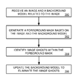
- FIG. 3 illustrates a flowchart of an image processing method for image ghost removal
- FIG. 4 illustrates an example background model within an embodiment of an image processing system for image ghost removal
- FIG. 5 illustrates an example foreground mask within an embodiment of an image processing system for image ghost removal
- FIG. 6 illustrates an example ghost within an embodiment of an image processing system for image ghost removal
- FIG. 7 illustrates an example background model including a ghost within an embodiment of an image processing system for image ghost removal
- FIG. 8 illustrates an example foreground mask without a ghost within an embodiment of an image processing system for image ghost removal.
- FIG. 1 illustrates imaging system 100 .
- Imaging system 100 comprises video source 102 and image processing system 104 .
- Video source 102 is configured to capture video data of scene 106 .
- scene 106 includes a plurality of elements. These elements include display 108 , display 110 , man 112 , woman 114 , coffee 116 , and stain 118 on top of display 108 .
- Video source 102 may comprise any device having the capability to capture video or images.
- Video source 102 comprises circuitry and an interface for transmitting video or images.
- Video source 102 may be a device which performs the initial optical capture of video, may be an intermediate video transfer device, or may be another type of video transmission device.
- video source 102 may be a video camera, still camera, internet protocol (IP) camera, video switch, video buffer, video server, or other video transmission device, including combinations thereof.
- IP internet protocol
- Image processing system 104 may comprise any device for processing or analyzing video, video streams, or images.
- Image processing system 104 comprises processing circuitry and an interface for receiving video.
- Image processing system 104 is capable of performing one or more processes on the video streams received from video source 102 .
- the processes performed on the video may include viewing, storing, transforming, mathematical computations, modifications, object identification, analytical processes, conditioning, other processes, or combinations thereof.
- Image processing system 104 may also comprise additional interfaces for transmitting or receiving video streams, a user interface, memory, software, communication components, a power supply, or structural support.
- Image processing system 104 may be a video analytics system, server, digital signal processor, computing system, or some other type of processing device, including combinations thereof.
- Video source 102 and image processing system 104 communicate via one or more links which may use any of a variety of communication media, such as air, metal, optical fiber, or any other type of signal propagation path, including combinations thereof.
- the links may use any of a variety of communication protocols, such as internet, telephony, optical networking, wireless communication, wireless fidelity, or any other communication protocols and formats, including combinations thereof.
- the link between video source 102 and image processing system 104 may be direct as illustrated or may be indirect and accomplished using other networks or intermediate communication devices.
- imaging system 100 may contain additional video sources, additional image processing systems, or other devices.
- FIG. 2 illustrates image processing system 200 .
- Image processing system 200 includes communication interface 210 and processing system 220 .
- Processing system 220 is linked to communication interface 210 through a communication link.
- Communication interface 210 includes network interface 212 , input ports 216 , and output ports 218 .
- Communication interface 210 includes components that communicate over communication links, such as network cards, ports, RF transceivers, processing circuitry and software, or some other communication device.
- Communication interface 210 may be configured to communicate over metallic, wireless, or optical links.
- Communication interface 210 may be configured to use TDM, IP, Ethernet, optical networking, wireless protocols, communication signaling, or some other communication format, including combinations thereof.
- Image processing system 200 may include multiple network interfaces.
- Network interface 212 is configured to connect to external devices over network 270 .
- Network interface 212 may be configured to communicate in a variety of protocols.
- Input ports 216 are configured to connect to input devices 280 such as a video source, a storage system, a keyboard, a mouse, a user interface, or other input device.
- Output ports 218 are configured to connect to output devices 290 such as a storage system, other communication links, a display, or other output devices.
- Processing system 220 includes processor 221 and memory system 222 .
- Processor 221 includes microprocessor, or other circuitry that retrieves and executes operating software from memory system 222 .
- Memory system 222 comprises software 223 .
- Memory system 222 may be implemented using random access memory, read-only memory, a hard drive, a tape drive, flash memory, optical storage, or other memory apparatus.
- Software 223 comprises operating system 224 , applications 225 , frame comparison module 228 , and background correction module 229 .
- Software 223 may also comprise additional computer programs, firmware, or some other form of non-transitory, machine-readable processing instructions.
- operating system 224 directs processing system 220 to operate image processing system 200 as described herein using applications 222 , frame comparison module 228 , and background correction module 229 .
- Frame comparison module 228 directs processing system 220 to compare current frames with the background model as described below.
- Background correction module 229 directs processing system 220 to correct the background model in those pixels where the foreground mask contains an incorrect detection as described below.
- FIG. 3 illustrates a flowchart of an image processing method for image ghost removal.
- an image and a background model related to the image are received in image processing system 200 , (operation 300 ).
- Image processing system 200 generates a foreground mask based on the image and the background model, (operation 302 ).
- this foreground mask may be generated by including all pixels in the image that differ from the background model in the foreground mask.
- Image processing system 200 identifies image ghosts within the foreground mask, (operation 304 ).
- Image ghosts may be considered image elements within the foreground mask that remain unchanged for a period of time.
- Image elements within the foreground mask that do not move for a set period of time are then identified as image ghosts.
- image ghosts may be identified by determining a length of time that each pixel in the foreground mask has been different from a corresponding pixel in the background image, and identifying a pixel as an image ghost pixel when the length of time for that pixel exceeds a criteria.
- image processing system 200 updates the background model to eliminate the image ghosts, (operation 306 ). This updating may be accomplished by overwriting pixels corresponding to the image ghost in the background model with the corresponding pixels in the image.
- the updated background model may now be stored in a memory.
- the image ghost may be removed from the foreground. In some embodiments this may be accomplished by clearing those pixels in the foreground mask associated with the image ghost, or by comparing the current image with the updated background mask.
- FIG. 4 illustrates an example background model 400 within an embodiment of an image processing system for image ghost removal.
- the examples illustrated in FIGS. 4 through 8 use scene 106 from FIG. 1 as captured by video source 102 and image processing system 104 as an example current image.
- This example background model 400 corresponding to scene 106 includes only display 108 and display 110 . Any image elements other than these two displays will be considered an image object in the foreground mask for this example.
- FIG. 5 illustrates an example foreground mask 500 within an embodiment of an image processing system for image ghost removal.
- This example foreground mask 500 includes all of the image objects found in scene 106 that are not included in background mask 400 .
- man 112 , woman 114 , coffee 116 , and stain 118 are considered foreground image elements and are included in foreground mask 500 .
- FIG. 6 illustrates an example ghost 600 within an embodiment of an image processing system for image ghost removal.
- stain 118 has remained unchanged for a long period of time exceeding the criteria to count it as an image ghost. Since man 112 , woman 114 , and coffee 116 from foreground mask 500 have not been stationary long enough to exceed the criteria, they are correctly categorized as foreground elements within foreground mask 500 .
- FIG. 7 illustrates an example background model including a ghost 700 within an embodiment of an image processing system for image ghost removal.
- this example background model 400 has been updated to include the image ghost stain 118 resulting in an updated background model 700 .
- FIG. 8 illustrates an example foreground mask without a ghost 800 within an embodiment of an image processing system for image ghost removal.
- updated background model 700 when updated background model 700 is used to process scene 106 , three foreground image elements remain in foreground mask 800 : man 112 , woman 114 , and coffee 116 .
- the elimination of stain 118 as a foreground image element allows for faster processing of the three remaining foreground image elements since no longer is computer or user time wasted on analysis of stain 118 .
- Cyclic_Frame_Buffer stores a total of PARAM_BUFFER_SIZE images from the past, each image is recorded PARAM_BUFFER_SPACING seconds from the previous image.
- Dead_Pixel_Map is an array containing counts for each pixel the number of seconds that it has been continuously flagged as a ghost in the foreground mask. The array is updated every PARAM_DPM_UPDATE_RATE seconds. To save memory, the value saturates (i.e. reaches a maximum value) at 255 seconds.
- Every PARAM_WORK_RATE seconds the binary components of the foreground mask are examined. This may be accomplished by examining all of the detected objects in the current frame or by examining all connected components in the foreground mask. Those objects that exist for less than PARAM_OBJ_MIN_AGE seconds are ignored. The binary mask components which are associated with each detected object are then examined.
- the oldest image in the Cyclic_Frame_Buffer is retrieved.
- the SSD score over the area of the inspected binary mask components between the oldest image and the current image is calculated.
- Binary mask components whose result exceeds PARAM_SSD_MIN_VALUE are skipped.
- the binary mask components that have passed the two tests above are declared as still. Any detected objects associated with that binary mask component are disabled and/or killed, and the background model where the binary mask components are located is updated according to the value of the binary mask component in the current image.
- PARAM_OBJ_MIN_AGE 5
- PARAM_DPM_MIN_VALUE 20
- the Dead_Pixel_Map array may be built using an exponential decay memory mechanism.
- dt is a predetermined period of time, such as a second.
- an element within a scene may initially appear to be static, and thus be improperly flagged as a ghost.
- some embodiments measure an amount of motion within the static region to ensure that the element is not actually a foreground element instead of a ghost. If motion is detected within the static region, the element is identified as a proper element of the foreground mask.
- a gradient is calculated around the border of the ghost within the current image to ensure that the ghost is still relevant and not formed by a temporary change or noise. If the element is actually a ghost, no meaningful gradients should be found. If gradients are found in the current image, it's likely that the element is not a ghost and belongs in the foreground mask.
Abstract
Description
Claims (21)
Priority Applications (1)
| Application Number | Priority Date | Filing Date | Title |
|---|---|---|---|
| US13/352,642 US9218669B1 (en) | 2011-01-20 | 2012-01-18 | Image ghost removal |
Applications Claiming Priority (2)
| Application Number | Priority Date | Filing Date | Title |
|---|---|---|---|
| US201161434701P | 2011-01-20 | 2011-01-20 | |
| US13/352,642 US9218669B1 (en) | 2011-01-20 | 2012-01-18 | Image ghost removal |
Publications (1)
| Publication Number | Publication Date |
|---|---|
| US9218669B1 true US9218669B1 (en) | 2015-12-22 |
Family
ID=54847994
Family Applications (1)
| Application Number | Title | Priority Date | Filing Date |
|---|---|---|---|
| US13/352,642 Expired - Fee Related US9218669B1 (en) | 2011-01-20 | 2012-01-18 | Image ghost removal |
Country Status (1)
| Country | Link |
|---|---|
| US (1) | US9218669B1 (en) |
Cited By (3)
| Publication number | Priority date | Publication date | Assignee | Title |
|---|---|---|---|---|
| CN105825170A (en) * | 2016-03-10 | 2016-08-03 | 浙江生辉照明有限公司 | Detection method and apparatus for repeated gesture |
| CN111476747A (en) * | 2020-03-31 | 2020-07-31 | 深圳奥比中光科技有限公司 | System and method for eliminating ghost image in under-screen imaging |
| US11054108B2 (en) | 2017-01-17 | 2021-07-06 | Signify Holding B.V. | Adjustable spot light position generation |
Citations (13)
| Publication number | Priority date | Publication date | Assignee | Title |
|---|---|---|---|---|
| US6570608B1 (en) * | 1998-09-30 | 2003-05-27 | Texas Instruments Incorporated | System and method for detecting interactions of people and vehicles |
| US20050089194A1 (en) * | 2003-10-24 | 2005-04-28 | Matthew Bell | Method and system for processing captured image information in an interactive video display system |
| US20070195993A1 (en) * | 2006-02-22 | 2007-08-23 | Chao-Ho Chen | Method for video object segmentation |
| US7436887B2 (en) * | 2002-02-06 | 2008-10-14 | Playtex Products, Inc. | Method and apparatus for video frame sequence-based object tracking |
| US20090060278A1 (en) * | 2007-09-04 | 2009-03-05 | Objectvideo, Inc. | Stationary target detection by exploiting changes in background model |
| US20090087096A1 (en) * | 2007-09-27 | 2009-04-02 | John Eric Eaton | Background-foreground module for video analysis system |
| US20090244390A1 (en) * | 2008-03-25 | 2009-10-01 | Rogerio Schmidt Feris | Real time processing of video frames for triggering an alert |
| US20100290710A1 (en) * | 2009-04-22 | 2010-11-18 | Nikhil Gagvani | System and method for motion detection in a surveillance video |
| US7957592B2 (en) * | 2006-11-30 | 2011-06-07 | Industrial Technology Research Institute | Video object segmentation method and system |
| US20110280478A1 (en) * | 2010-05-13 | 2011-11-17 | Hon Hai Precision Industry Co., Ltd. | Object monitoring system and method |
| US20120162416A1 (en) * | 2010-12-22 | 2012-06-28 | Pelco, Inc. | Stopped object detection |
| US20120173577A1 (en) * | 2010-12-30 | 2012-07-05 | Pelco Inc. | Searching recorded video |
| US20120183177A1 (en) * | 2011-01-17 | 2012-07-19 | Postech Academy-Industry Foundation | Image surveillance system and method of detecting whether object is left behind or taken away |
-
2012
- 2012-01-18 US US13/352,642 patent/US9218669B1/en not_active Expired - Fee Related
Patent Citations (13)
| Publication number | Priority date | Publication date | Assignee | Title |
|---|---|---|---|---|
| US6570608B1 (en) * | 1998-09-30 | 2003-05-27 | Texas Instruments Incorporated | System and method for detecting interactions of people and vehicles |
| US7436887B2 (en) * | 2002-02-06 | 2008-10-14 | Playtex Products, Inc. | Method and apparatus for video frame sequence-based object tracking |
| US20050089194A1 (en) * | 2003-10-24 | 2005-04-28 | Matthew Bell | Method and system for processing captured image information in an interactive video display system |
| US20070195993A1 (en) * | 2006-02-22 | 2007-08-23 | Chao-Ho Chen | Method for video object segmentation |
| US7957592B2 (en) * | 2006-11-30 | 2011-06-07 | Industrial Technology Research Institute | Video object segmentation method and system |
| US20090060278A1 (en) * | 2007-09-04 | 2009-03-05 | Objectvideo, Inc. | Stationary target detection by exploiting changes in background model |
| US20090087096A1 (en) * | 2007-09-27 | 2009-04-02 | John Eric Eaton | Background-foreground module for video analysis system |
| US20090244390A1 (en) * | 2008-03-25 | 2009-10-01 | Rogerio Schmidt Feris | Real time processing of video frames for triggering an alert |
| US20100290710A1 (en) * | 2009-04-22 | 2010-11-18 | Nikhil Gagvani | System and method for motion detection in a surveillance video |
| US20110280478A1 (en) * | 2010-05-13 | 2011-11-17 | Hon Hai Precision Industry Co., Ltd. | Object monitoring system and method |
| US20120162416A1 (en) * | 2010-12-22 | 2012-06-28 | Pelco, Inc. | Stopped object detection |
| US20120173577A1 (en) * | 2010-12-30 | 2012-07-05 | Pelco Inc. | Searching recorded video |
| US20120183177A1 (en) * | 2011-01-17 | 2012-07-19 | Postech Academy-Industry Foundation | Image surveillance system and method of detecting whether object is left behind or taken away |
Cited By (4)
| Publication number | Priority date | Publication date | Assignee | Title |
|---|---|---|---|---|
| CN105825170A (en) * | 2016-03-10 | 2016-08-03 | 浙江生辉照明有限公司 | Detection method and apparatus for repeated gesture |
| CN105825170B (en) * | 2016-03-10 | 2019-07-02 | 浙江生辉照明有限公司 | Toward the detection method and device of renaturation gesture |
| US11054108B2 (en) | 2017-01-17 | 2021-07-06 | Signify Holding B.V. | Adjustable spot light position generation |
| CN111476747A (en) * | 2020-03-31 | 2020-07-31 | 深圳奥比中光科技有限公司 | System and method for eliminating ghost image in under-screen imaging |
Similar Documents
| Publication | Publication Date | Title |
|---|---|---|
| CN108509941B (en) | Emotion information generation method and device | |
| CN109299703B (en) | Method and device for carrying out statistics on mouse conditions and image acquisition equipment | |
| CN108337505B (en) | Information acquisition method and device | |
| US8879789B1 (en) | Object analysis using motion history | |
| CN109145771B (en) | Face snapshot method and device | |
| CN111985281B (en) | Image generation model generation method and device and image generation method and device | |
| US20140233802A1 (en) | Increased Quality of Image Objects Based on Depth in Scene | |
| CN110784644B (en) | Image processing method and device | |
| CN106791815A (en) | Method and apparatus for determining the acquisition time of image | |
| US11694331B2 (en) | Capture and storage of magnified images | |
| US9864871B2 (en) | Masking of haptic data | |
| US9218669B1 (en) | Image ghost removal | |
| CN111444555A (en) | Temperature measurement information display method and device and terminal equipment | |
| CN112749647B (en) | Intelligent cashing inspection method and system based on monitoring video | |
| CN111126159A (en) | Method, apparatus, electronic device, and medium for tracking pedestrian in real time | |
| US9286664B2 (en) | System and method for blind image deconvolution | |
| US10438066B2 (en) | Evaluation of models generated from objects in video | |
| CN116128922A (en) | Object drop detection method, device, medium and equipment based on event camera | |
| CN113158773B (en) | Training method and training device for living body detection model | |
| CN113628192A (en) | Image blur detection method, device, apparatus, storage medium, and program product | |
| CN112153320A (en) | Method and device for measuring size of article, electronic equipment and storage medium | |
| CN111191593A (en) | Image target detection method and device, storage medium and sewage pipeline detection device | |
| CN110210306B (en) | Face tracking method and camera | |
| EP3506199A1 (en) | Method for enhancing visual quality of videos | |
| CN110909579A (en) | Video image processing method and device, electronic equipment and storage medium |
Legal Events
| Date | Code | Title | Description |
|---|---|---|---|
| AS | Assignment |
Owner name: VERINT SYSTEMS LTD., ISRAEL Free format text: ASSIGNMENT OF ASSIGNORS INTEREST;ASSIGNORS:GOLAN, OREN;HOROVITZ, ITSHAK;REEL/FRAME:027972/0312 Effective date: 20120119 |
|
| STCF | Information on status: patent grant |
Free format text: PATENTED CASE |
|
| MAFP | Maintenance fee payment |
Free format text: PAYMENT OF MAINTENANCE FEE, 4TH YEAR, LARGE ENTITY (ORIGINAL EVENT CODE: M1551); ENTITY STATUS OF PATENT OWNER: LARGE ENTITY Year of fee payment: 4 |
|
| AS | Assignment |
Owner name: COGNYTE TECHNOLOGIES ISRAEL LTD, ISRAEL Free format text: CHANGE OF NAME;ASSIGNOR:VERINT SYSTEMS LTD.;REEL/FRAME:060751/0532 Effective date: 20201116 |
|
| AS | Assignment |
Owner name: COGNYTE TECHNOLOGIES ISRAEL LTD, ISRAEL Free format text: CHANGE OF NAME;ASSIGNOR:VERINT SYSTEMS LTD.;REEL/FRAME:059710/0742 Effective date: 20201116 |
|
| FEPP | Fee payment procedure |
Free format text: MAINTENANCE FEE REMINDER MAILED (ORIGINAL EVENT CODE: REM.); ENTITY STATUS OF PATENT OWNER: LARGE ENTITY |
|
| LAPS | Lapse for failure to pay maintenance fees |
Free format text: PATENT EXPIRED FOR FAILURE TO PAY MAINTENANCE FEES (ORIGINAL EVENT CODE: EXP.); ENTITY STATUS OF PATENT OWNER: LARGE ENTITY |
|
| STCH | Information on status: patent discontinuation |
Free format text: PATENT EXPIRED DUE TO NONPAYMENT OF MAINTENANCE FEES UNDER 37 CFR 1.362 |
|
| FP | Lapsed due to failure to pay maintenance fee |
Effective date: 20231222 |