US9219403B2 - Magnetic shear force transfer device - Google Patents
Magnetic shear force transfer device Download PDFInfo
- Publication number
- US9219403B2 US9219403B2 US13/604,939 US201213604939A US9219403B2 US 9219403 B2 US9219403 B2 US 9219403B2 US 201213604939 A US201213604939 A US 201213604939A US 9219403 B2 US9219403 B2 US 9219403B2
- Authority
- US
- United States
- Prior art keywords
- magnetic
- concentric circular
- tracks
- shear
- sources
- Prior art date
- Legal status (The legal status is an assumption and is not a legal conclusion. Google has not performed a legal analysis and makes no representation as to the accuracy of the status listed.)
- Expired - Fee Related, expires
Links
Images


Classifications
-
- H—ELECTRICITY
- H02—GENERATION; CONVERSION OR DISTRIBUTION OF ELECTRIC POWER
- H02K—DYNAMO-ELECTRIC MACHINES
- H02K49/00—Dynamo-electric clutches; Dynamo-electric brakes
- H02K49/10—Dynamo-electric clutches; Dynamo-electric brakes of the permanent-magnet type
- H02K49/104—Magnetic couplings consisting of only two coaxial rotary elements, i.e. the driving element and the driven element
- H02K49/108—Magnetic couplings consisting of only two coaxial rotary elements, i.e. the driving element and the driven element with an axial air gap
-
- H—ELECTRICITY
- H02—GENERATION; CONVERSION OR DISTRIBUTION OF ELECTRIC POWER
- H02K—DYNAMO-ELECTRIC MACHINES
- H02K2213/00—Specific aspects, not otherwise provided for and not covered by codes H02K2201/00 - H02K2211/00
- H02K2213/03—Machines characterised by numerical values, ranges, mathematical expressions or similar information
Definitions
- the present invention relates generally to a magnetic shear force transfer device. More particularly, the present invention relates to magnetic shear force transfer devices comprising multi-pole correlated magnetic structures that enable couplings and gears having high ratios of torque to magnetic material volume.
- magnetic couples and gears have heretofore been extremely limited in their application by their low torque densities (i.e., torque per volume of couple or gear mechanism). Higher torque densities would translate directly into broader applications for magnetic gears and couples.
- the first and second patterns define the print location and polarity of each magnetic source of the first and second pluralities of magnetic sources.
- the first pattern corresponds to a first plurality of concentric circular tracks and the second pattern corresponds to a second plurality of concentric circular tracks.
- Each concentric circular track of the first plurality of concentric circular tracks has an even number of magnetic sources and each concentric circular track of the second plurality of concentric circular tracks has an even number of magnetic sources.
- Adjoining magnetic sources alternate in polarity in each circular track of said first plurality of concentric circular tracks and said plurality of concentric circular tracks.
- One or more tracks of the first plurality of concentric circular tracks are rotated relative to one or more tracks of the second plurality of concentric circular tracks such that a maximum torque condition coincides to one angular orientation between the first and second magnetic structures.
- the distances between print positions of adjoining magnetic sources and the amounts of magnetizing current used to generate H fields that create adjoining opposite polarity B fields in said first and second magnetizable material are selected to produce a desired force profile that may correspond to a force versus distance curve or a torque versus a rotation of said first magnetic structure relative to said second magnetic structure.
- Shear forces can be transferred as torque and the non-magnetic gap can be an air gap.
- a first shunt plate can be positioned on a back side of the first magnetic structure and a second shunt plate can be positioned on a back side of the second magnetic structure.
- An intermediate layer can be located between the first magnetic structure and the second magnetic structure, where the intermediate layer is a non-magnetic material.
- a method for manufacturing a magnetic shear force transfer device for transferring shear forces across a non-magnetic gap includes producing a first magnetic structure by magnetically printing a first plurality of magnetic sources into a first magnetizable material in accordance with a first pattern and producing a second magnetic structure by magnetically printing a second plurality of magnetic sources into a second magnetizable material in accordance with a second pattern, where the first and second patterns define the print location and polarity of each magnetic source of said first and second pluralities of magnetic sources.
- the first pattern corresponds to a first plurality of concentric circular tracks and the second pattern corresponds to a second plurality of concentric circular tracks.
- Each concentric circular track of said first plurality of concentric circular tracks has an even number of magnetic sources and each concentric circular track of said second plurality of concentric circular tracks has an even number of magnetic sources.
- Adjoining magnetic sources alternate in polarity in each circular track of said first plurality of concentric circular tracks and said second plurality of concentric circular tracks.
- One or more tracks of the first plurality of concentric circular tracks are rotated relative to one or more tracks of the second plurality of concentric circular tracks such that a maximum torque condition coincides to one angular orientation between said first and second magnetic structures.
- the method may also include determining a desired distance between print positions of adjoining magnetic sources and desired amounts of magnetizing current used to generate H fields that create adjoining opposite polarity B fields in a magnetizable material that produce a desired force profile, wherein distances between print positions of adjoining magnetic sources substantially correspond to the desired distance and the amounts of magnetizing current used to generate H fields that create adjoining opposite polarity B fields in said first and second magnetizable material substantially correspond to the desired amounts of magnetizing current.
- the shear forces are transferred as torque.
- the non-magnetic gap is an air gap.
- the desired force profile corresponds to a force versus distance curve or to a torque versus a rotation of said first magnetic structure relative to said second magnetic structure.
- the method may include providing a first shunt plate on a back side of the first magnetic structure and providing a second shunt plate on a back side of the second magnetic structure.
- the method may also include providing an intermediate layer between the first magnetic structure and the second magnetic structure, where the intermediate layer is a non-magnetic material.
- FIG. 1 depicts exemplary complementary two dimensional codes and corresponding field scans and spatial force function
- FIG. 2 depicts an exemplary magnetic printer
- FIG. 3 depicts an exemplary alternating block pattern
- FIG. 4 depicts an exemplary triangle pattern
- FIG. 5 depicts an exemplary continuously varying field structure
- FIG. 6 depicts three exemplary maxel patterns
- FIG. 7 depicts an exemplary shear test apparatus
- FIG. 8 depicts filed intensity around the continuously varying pattern
- FIG. 9 depicts an exemplary aspect ratio effect on shear force
- FIG. 10 depicts exemplary shear and shear density for alternating blocks
- FIG. 11 depicts exemplary alternating blocks and simulated maxel shear force reduction with plate separation
- FIG. 12 depicts exemplary alternating block shear stress and density from Maxwell
- FIG. 13 depicts exemplary field intensity and lines at maximum shear for the triangle pattern
- FIG. 14 depicts exemplary shear stress and density versus ratio of triangle with to thickness
- FIG. 15 depicts field intensity for continuously varying pattern
- FIG. 16 depicts field lines for continuously varying pattern
- FIG. 17 depicts exemplary shear stress and density for the continuously varying pattern
- FIG. 18 depicts an exemplary shear density comparison of continuously varying and alternating block patterns
- FIG. 19 depicts an exemplary diagram of simulated maxel variables
- FIG. 20 depicts exemplary shear stress and shear density for simulated maxels
- FIG. 21 depicts exemplary shear stress versus displacement for various codes
- FIG. 22 depicts exemplary shear stress versus plate offset for various codes
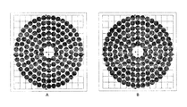
- FIG. 23 depicts an exemplary magnetic shear force transfer device comprising two magnetic structures
- FIG. 24 depicts another exemplary magnetic shear force transfer device comprising two magnetic structures
- FIG. 25 depicts exemplary torque density versus offset between the disks of FIG. 24 ;
- FIG. 26 depicts an exemplary torque estimate over 90 degrees rotation of the first magnetic structure of FIG. 24 relative to the second magnetic structure of FIG. 24 ;
- FIG. 27 depicts an exemplary torque estimate over a complete 360 degree rotation of the first magnetic structure of FIG. 24 relative to the second magnetic structure of FIG. 24 .
- magnets The behavior of magnets is well understood and, aside from materials improvements such as rare-earth materials, magnets have been used in much the same way for the more than a century. During this time, machines have been designed to work with the fixed behavior of permanent magnets that have a North Pole and a South Pole, where the field magnitude decreases with the square of the separation distance between two magnets.
- CMR Correlated Magnetics Research
- Barker codes http://en.wikipedia.org/wiki/Barker_code
- RF radio frequency
- a two-dimensional code would constructively interfere with correlation in two dimensions simultaneously.
- Such a code has been printed into the surface of magnetic material 102 a 102 b to produce a pair of magnetic structures where constructive interference refers to force between the structures and correlation translates to spatial alignment of the magnetic structure pair.
- FIG. 1 illustrates codes A 104 a and A′ 104 b (shown as patterns of light and dark colored circles that represent “North up” and “South up” polarity maxels), the complex fields 106 a 106 b resulting from magnetizing the codes 104 a 104 b into permanent magnet substrates 102 a 102 b and finally the spatial force function 108 corresponding to relative alignments of the two magnetic structures magnetized in accordance with code A and complementary (mirror image) code A′, respectively.
- the peak spatial force in the center of the spatial force function 108 corresponds to the strong attracting force that is only produced when the magnetic structures are aligned. For other alignments, attract and repel forces are produced that substantially cancel. This is one example of many different spatially-dependent behaviors that can be programmed into magnetic material.
- the principle codes and magnetic fields also extend to arrays of electromagnets or electro-permanent magnets, which enable complex magnetic fields to vary with time.
- a magnetization pattern of 120 2 mm outside diameter (OD) maxels can be printed into a standard N 42 , 1 ⁇ 8′′ thick 1.5′′ OD disc of Neodymium Iron Boron at room temperature in 10 to 15 seconds.
- CMR's, 4 th Generation magnetic printer trademarked MagPrinterTM is shown in FIG. 2 . Planned improvements in machine architecture, positioning and electronics are expected to reduce the “printing” time by an order of magnitude.
- MaxField® A collection of magnetization technologies trademarked MaxField® have been developed by CMR that allow Polymagnets to be optimized for tensile force achieving a 500% mated force increase over conventional, un-coded pairs of magnets of the same material and size. These techniques specifically involve using a magnetizing circuit to magnetically print (i.e., spot magnetize) maxels into a particular grade and thickness of magnetizable material where an amount of magnetizing current is selected to produce an H field required to produce a B field in the magnetizable material such that adjoining opposite polarity maxels having a selected spacing will have a desired force profile.
- a magnetizing circuit to magnetically print (i.e., spot magnetize) maxels into a particular grade and thickness of magnetizable material where an amount of magnetizing current is selected to produce an H field required to produce a B field in the magnetizable material such that adjoining opposite polarity maxels having a selected spacing will have a desired force profile.
- the strength of the magnetizing field and the maxel spacing can be selected based on the properties of the material being magnetized to achieve desired tensile and/or shear force profiles of adjoining opposite polarity maxels where force curves can be designed in multiple directions and along complex three-dimensional paths.
- higher forces provide the same performance with less magnetic material, or an opportunity to upgrade lower energy-product magnetic materials to replace rare-earth materials.
- the CMR technologies support similar improvements in magnetic shear forces.
- CMR submitted a proposal and was awarded a Phase I Small Business Industrial Research (SBIR) contract to create improvements in shear forces and force densities between magnets using technologies invented by CMR.
- SBIR Small Business Industrial Research
- the proposal listed two goals: 1) quantify the potential of maxel arrays to increase the shear force between two magnetic structures and to improve the shear force to displacement curve, and 2) create maxel arrays that improve the torque/displacement curve by creating steeper torque onset and explore the potential for tailored torque/displacement behavior.
- the project included an extensive modeling effort aimed at understanding the nature of shear forces between magnets and magnetization patterns (sometimes also referred to as ‘codes’ or ‘arrays’) that provide high forces and force densities. This led to an exploration of the limits of magnetic torque transfer devices.
- the project was focused on devices that transfer forces directly between permanent magnets and not through modulating iron (like magnetic “shutter” gears) or via electromagnets. This project also resulted in the present invention.
- the shear forces between magnets provide the dominant factor determining the torque density of magnet-to-magnet torque transfer devices.
- the torque density is proportional to the shear area density between the magnets.
- the following equations, 1) illustrate how the torque density (T/V) is proportional to shear area density, or shear stress ( ⁇ ) for disk-to-disk and concentric cylinder architectures, respectively.
- T/V torque density
- ⁇ shear stress
- t refers to the thickness across both plates and ‘r’ to their radii.
- Clutches are similar to magnetic couples and represent an important benchmark for their performance Carbon-carbon clutches used in various racing applications can provide a maximum of 100N of shear force for each square cm of plate area.
- the shutter gear described by Atallah has a torque density of 78 kN-m/m ⁇ 3 as built (111 kN-m/m ⁇ 3 as modeled). This corresponds to a shear area density (shear stress) of 3.9 N/cm ⁇ 2 (5.5 N/cm ⁇ 2 as modeled) at the low speed surface and is the highest experimentally verified torque-density magnetic gearbox that has been described in the literature.
- the project objective was to produce a device that exceeds these numbers.
- CMR achieved this objective by developing a magnetic coupling that set a new standard for shear forces and torque densities.
- a magnetic shear force transfer device includes a first magnetic structure comprising a first plurality of magnetic sources arranged in accordance with a first polarity pattern and a second magnetic structure comprising a second plurality of magnetic sources arranged in accordance with a second polarity pattern.
- Preferred embodiments of such a shear force transfer device include co-axial cylinders and pairs of concentric disks with gaps that can be substantially thinner than the magnetic materials.
- the first pattern and second pattern each comprise a plurality of concentric tracks each having an even number of magnetic source positions.
- the magnetic sources in the tracks of one magnet in the pair can be rotated so that all tracks reach a maximum torque condition at the same angular position, thereby creating a maximum torque for the structure.
- Angular shifting of the tracks can also be used to tune the maximum torque between the first and second magnetic structures or to control the angular stiffness between them.
- Other relevant variables available to tune the torque and torque curve include the distance between magnetic source positions of the first and second patterns, the size or strength of the magnetic sources and the shapes of the tracks. More generally, magnetic sources can be organized into a wide variety of patterns that can produce a wide variety of torque profiles between the first and second magnetic structures. In one embodiment, the pattern is selected to substantially match a preferred distance determined to produce a maximum force between adjoining opposite polarity magnetic sources. The distance between the center-line of adjacent tracks of the first and second patterns can also be selected to match the preferred distance.
- the first and second magnetic structures of the present embodiment are referred to herein as plates or discs.
- Much of the disclosure describes a horizontal orientation of two plates such as shown in FIG. 3 , where one plate is called the upper plate and the other is called the lower plate. In this orientation the plates may also be called the top and bottom plates.
- two such plates can be in an orientation other than a horizontal orientation, other than a co-axial orientation and other than a concentric orientation.
- the two plates can be in a vertical orientation in which case the two plates might be referred to as the left plate and the right plate.
- the plates could have a non-uniform gap between them due to an angle between their axes or the plates could be offset a distance parallel to the gap between them.
- the plates are described herein as being circular discs since the SBIR primary application of interest involved magnetic couplings such as those that would be used in a rotating motor shaft. But, other movements such as a translational movement and other shapes such as rings, rectangular shapes, octagonal shapes, or other desired shapes are certainly possible.
- the exemplary magnetic couplings described herein have flat surfaces but other shaped surfaces are possible such as convex surfaces, concave surfaces, complex surfaces, compound surfaces, intermeshed surfaces, interdigitated surfaces and the like.
- Magnetic structures may comprise one or more pieces of magnetizable material which may include holes of various shapes or other materials present for spacing, structural, thermal, aesthetic or other purposes.
- the magnetic structures may have shunt plates or other magnetically active components on their back sides (i.e., the sides of the structures opposite the sides that are interfacing).
- One or more intermediate layers for example a non-magnetic layer, may be configured between two interfacing magnetic structures.
- the main source was Furlani's “Permanent Magnet and Electromechanical Devices”, [2] since the charge model, p. 132, relates magnetization, emitted fields and forces between permanent magnets together.
- CMR Prior to the SBIR project, CMR developed an internal modeling software system to support the development of maxel patterns and the analysis of various magnetic structures. CMR's modeling software was used to support the development of appropriate maxel patterns for high shear and high torque magnets. CMR also used the Ansys Maxwell electromagnetic field simulation software.
- the modeling work performed during this project was focused on the scaling of substrate thickness, feature size and aspect ratio, and magnetization patterns in terms of their influence the shear forces between magnets.
- the first modeling study used software developed by CMR to assemble substrates (digitally) from arrays of bars with alternating polarity aligned in the ‘z’ direction such as in FIG. 3 , which depicts two plates having an alternating block pattern.
- the top plate would initially be aligned with the lower plate (in ‘x’) and offset a distance away in ‘z’. Shear forces are set up by a displacement in ‘x’. In some of the models described below this displacement is achieved by a phase shift in ‘x’ to leave the area directly between the two plates constant.
- feature size represents the fundamental dimension of the pattern. In the ‘alternating block’ pattern illustrated in FIG. 3 , the feature size is the width of a single block, ‘w’.
- the blocks had different cross section ratios (in width ‘w’ versus thickness ‘t’) as viewed in the X-Z plane.
- the individual bars extended in the Y direction (into the page) to create square substrates.
- the shear forces versus displacement were calculated for different aspect ratios (t/w) of these blocks.
- feature size refers here to the width of the blocks, ‘w’.
- a square substrate 96 mm on a side was built from blocks with equal width and thickness.
- the blocks modeled were 8, 4, 2, 1 and 0.5 mm thick.
- Maxwell includes ferromagnetism, permeability and other magnetic material details that have not been integrated into the internally developed CMR software.
- the magnetization vectors of the triangles with bases touching the active surface (the one emitting the field) are orthogonal to the surface and of alternating direction (in and out).
- the triangles with bases on the back surface also have alternating magnetization vectors—they point toward the outbound oriented front-side triangles and away from those with inbound orientations.
- the feature size was set to the width of the triangle bases and the ratios of triangle bases to triangle heights, which is also the substrate thickness, were explored.
- the widths chosen were 1 mm, 2 mm, 4 mm, and 8 mm and the substrates were 96 mm across (in ‘x’).
- the focus was on exploring the dependence of the ratio of the triangle widths to their heights. Ratios of 0.25 to 3 were examined using the model.
- the next 2D model was setup only within the Maxwell software. It used a series of thin slices of material to approximate a substrate with a continuously rotating magnetization vector. The vector rotates counter-clockwise with increasing ‘x’. This model was used to explore the effect of a magnetization profile that was expected to have exceptional shear performance. To align with the other modeling efforts, the substrate was built to extend 96 mm in ‘x’, wavelengths of 1, 2, 4, and 8 mm were examined with the substrate thickness set to equal the wavelength. Instead of moving the top plate, which inherently changes the areas that are interacting in shear, the phase of the magnetization vector was shifted to a reach a maximum shear condition.
- FIG. 5 illustrates the setup of the continuously varying field structure model and the field lines emitted by the structures, which are nearly confined to the region between the plates.
- the offset between the plates is relatively large in this figure and they are shown in a maximum shear condition.
- FIG. 6 illustrates three codes that were examined during the experimental work.
- the MF (or MaxField) code resembles a checkerboard pattern.
- the 31 code has in one direction alternating groups of three maxels of the same polarity and in a perpendicular direction has alternating single maxels.
- the MS code is a MaxField stripe pattern where the maxels of each stripe are shifted by a half maxel width from each other.
- a shear force test apparatus is shown in FIG. 7 .
- a 50 lb. bending-bar sensor can be seen toward the center of the image and an X-Y table was used to move the magnets from left to right during shear force tests.
- the spatial frequency of repeating patterns is an important factor in the shear force produced, and especially in terms of the shear force per volume of magnetic material.
- the other important factor is related to the pattern of magnetization within the substrate, including the creation of a one-sided field emission structure that maximizes the interaction between the two plates.
- the triangle and continuously varying patterns, outlined below, illustrate the role of magnetization in generating shear forces between magnets.
- Furlani [2] introduces a very useful magnetic charge model which applies to the present discussion.
- the field of a permanent magnet can be expressed as an integral function of its magnetization, as shown in Equation 2. While the details of this equation are beyond the scope of the present discussion, it is the launching point for the analytical work that has become a part of this project and will form the first section of the shear force journal article that is being prepared based on the work outlined in this report.
- Equation 3 defines a continuously rotating magnetization vector of a spatial frequency ‘f’ in a rectangular magnet having a length ‘2a’. This magnetization pattern was modeled and the results are described below.
- Furlani's charge model can also be applied to the forces between two permanent magnets by integrating the field from the first magnet multiplied by the magnetization of the second, as shown in Equation 4.
- the shear comes from the interaction of the gradient of B-field from magnet 1 (here “B 1 ”), with the magnetization of the second magnet, M.
- B 1 the gradient of B-field from magnet 1
- M the magnetization of the second magnet
- FIG. 9 illustrates the first modeling study performed using CMR's simulation software.
- the highest shear force comes from a 1:1 ratio of feature size (the width of each block) to substrate thickness.
- the other interesting effect, which is expected, is that the falloff in force is lower for the thickest magnets.
- the ratio of force between zero and 1 ⁇ 2w (half a block width) offset between magnets is much smaller for higher aspect ratios. This is an effect examined in more detail below.
- FIG. 10 illustrates the scaling effects discovered during the ‘alternating block’ simulation study.
- Several square substrates were assembled in the simulation software, each 96 mm on a side.
- Five different experiments were run with feature sizes of 8 , 4 , 2 , 1 and 0.5 mm.
- the substrate thickness was matched to the feature size, giving a 1:1 aspect ratio.
- the highest forces were at a zero offset—achievable only in simulation.
- At a 0.5 mm offset the curves look very different.
- the shear stress falls as the block widths are decreased, since the 0.5 mm offset is a more significant offset for smaller blocks.
- the shear density of the 0.5 mm offset curve peaks at a 1 mm block width and then falls to almost half that value for an 8 mm block width.
- the CMR technologies grew from applying signal processing and coding theories to magnetic fields.
- One way of looking at the graph in FIG. 12 is to see the feature size ‘w’ as the inverse of spatial frequency and shear force attenuating with the distance between the plates ‘t’.
- High spatial frequencies relate to more rapid force attenuation.
- the ‘alternating block’ pattern represents a square wave, which is equivalent to a Fourier Series (which for a square wave is sinusoidal curves having odd multiples of the base spatial frequency). If this is the case, the base spatial frequency is the dominant contributor to shear force at a particular offset. Based on this perspective, it was expected that the maximum shear force will come from some type of repeating, sinusoid-like magnetization pattern which would fall off more slowly with increasing offset. As is shown by the modeling effort in Maxwell, this is only partly true.
- the 2D alternating block model built in the Maxwell simulation software shows several important differences with the results from the internally developed CMR software (with reference to FIG. 12 ).
- the shear stresses are higher. Even with the offsets pegged to the feature sizes, the shear stresses remain surprisingly constant as the widths (which are set to be equal to the substrate thicknesses) get smaller.
- the shear densities predictably double as the thicknesses are cut in half.
- the maximum shear stress (48N/cm ⁇ 2) of the triangle pattern as calculated by the CMR software is not significantly different from the alternating blocks or simulated maxel studies described above, and may stem from differences in the models themselves.
- the shear densities did change, but in an expected way.
- For alternating blocks, a 1 mm feature size led to a shear density of 160N/cc.
- the shear density calculated for 1 mm simulated maxels was 240N/cc.
- a 1 mm feature size was calculated to have a shear density of 467N/cc. Since the substrates are scaled to 1 ⁇ 2 the feature size, the shear densities were nearly double that of the simulated maxel study.
- FIG. 13 A section of the Maxwell triangle pattern model oriented at a maximum shear condition is illustrated in FIG. 13 .
- the leaning field lines indicate a shear force between the structures. Even from this short section it is clear that this is largely a one-sided structure.
- the ratio of the triangle widths to the thickness of the substrate in this image is 2:1.
- the shear stresses and shear densities for the triangle pattern are shown in FIG. 14 plotted against the ratio of triangle width to substrate thickness.
- the best ratio for shear stress is about 0.75, while larger ratios (indicating flatter triangles and thinner substrates) correspond to higher shear densities.
- This is similar to the behavior of the alternating block model that was built using the internally developed CMR simulation software (illustrated in FIG. 10 , above).
- maximum shear forces come from thick magnets, while the most efficient use of magnetic material (force per volume) comes from an alternating pattern with a spatial wavelength of about 4 times the offset. For other magnetization patterns this ratio may be somewhat different, but the same basic pattern should apply. This relationship between offset and spatial wavelength has significant impact in the design of magnetic gears and couples.
- the gap that can be held between magnets determines a fundamental limit on the shear density for the magnets and also sets the range of spatial wavelengths for the magnetization pattern in those magnets. That said, there are additional geometric considerations that must be taken into account to translate the results of these flat-plate models into design guidelines for magnetic couples or gears. More discussion about this topic may be found below.
- FIGS. 15 and 16 The field intensity and field lines surrounding the continuously varying (CV) pattern are illustrated in FIGS. 15 and 16 , respectively. These figures illustrate how the field from these magnetic structures is emitted almost entirely toward the opposing magnet.
- the rightward skew of the field lines in FIG. 16 indicate a shear force on the top magnet structure.
- the layered structure of the models is also visible in these images, although the shear force data was obtained using 12 or more slices per spatial wavelength, while only 5-6 slices per wavelength are illustrated in the figures.
- the shear stress and shear density graph for the CV pattern looks very much like the one from the alternating block model above, except the numbers are much higher. Instead of 28N/cm 2 for the alternating blocks, or 55N/cm 2 for the triangle pattern, the CV pattern generates 71N/cm 2 according to the model. For a w/10 offset, the triangle pattern is capable of matching the shear density of the CV pattern for high ratios of width to substrate thickness.
- the only source of shear force in the alternating block would be the third term in the brackets (see Equation 6) since the magnetization in that pattern is only oriented in the ‘z’ direction.
- the magnetization rotates through both the ‘z’ and ‘x’ directions, which allows field gradients in the ‘x’ direction to also be a source of shear force.
- a simulation of spot magnetization was built using a dipole model and a simplified magnetization model of the substrate.
- the setup of that model is illustrated in FIG. 19 .
- patterns of numerical maxels were created that represented the CMR magnetization process, which were used to calculate the forces between two maxel patterns.
- the feature size was the distance between two adjacent maxels, the “X-step”.
- the head was approximated by a dipole set at some altitude above the substrate.
- the shear stress and shear density curves were similar to the ones generated during the alternating block study. Similar to the scaling of alternating blocks and the CV pattern, smaller maxels increase shear density while larger maxels increase shear stress.
- the maximum shear stress was 42N/cm ⁇ 2—which is surprising. It is not significantly higher than the alternating block study performed using CMR software.
- the shear density (N/cc) is 50% higher, which indicates some magnetic circuit characteristics in the substrate that resemble one-sided field structures.
- CMR produced a 3D field probe apparatus with a 40 ⁇ , 3-axis Hall-effect probe.
- This device enables a far more comprehensive exploration of the fields emitted from individual maxels, and arrays of maxels created under a variety of conditions.
- This capability combined with the development of a more representative magnetization model in Maxwell, will support improvements to the CMR magnetization process, to include speed, maxel profiles, and more accurate assessment, and allow maxel arrays to be designed to make better use of the magnetic material.
- FIG. 21 A single pass of shear force data for a selection of codes is shown in FIG. 21 , which illustrates several different shear force behaviors and the performance of the instrumentation system used to obtain the data.
- the shear forces reach a maximum at about one-half the displacement between maxels (in the ‘x’ direction).
- the notable exception is the 325 Code that was expected to span 3.25 mm.
- the shear forces for the 325 Code magnets exhibit shear forces that do not reverse completely, and also deviate from a sinusoid. Instead they are stronger in one direction, which skews the observed period. This presents an interesting ratcheting function due to the effects of magnetization order that is possible using arrays of maxels for shear force or torque.
- FIG. 23 Another important comparison in FIG. 23 is between the 325, 375, MS and 475 Codes. These are all codes that feature stripes of alternating maxels extending across the magnets (in the ‘y’ direction), though the MS Code has a slightly different architecture. The 325 and 475 Codes remain below about 8N/cm 2 while the MS and 375 reach 13 and 14.5N/cm 2 , respectively. These are good results compared to the shear stresses of existing magnetic gears, which range from about 3 to 5N/cm 2 . Of course, the critical variable in this comparison is the offset between magnets. All of the magnets tested here were square magnets, 25 mm on a side. A 0.5 mm offset between magnets of this scale represents a relatively wide tolerance. As illustrated in FIG.
- the 375 and MS Codes retain shear stresses that are about 11.5N/cm 2 at an offset of 0.5 mm. It is also interesting to compare the MF and MS codes in this figure.
- the MF Code has roughly equivalent variation in ‘x’ and ‘y’ and the force predictably falls off more rapidly than the MS code.
- Maxwell models predict far higher shear forces for both the alternating block and CV patterns. Additional work will be necessary to determine the sources of these differences and more importantly, to find available techniques for increasing the forces exhibited by maxel arrays.
- HT high torque
- the innermost tracks of the B magnet of FIG. 23 are rotated so the maximum torque condition of each track coincides to one angular orientation between the two magnets.
- FIGS. 23 and 24 The spatial layouts for the six maxel tracks of the codes of FIGS. 23 and 24 are provided in Table 3, where in FIG. 23 Magnet B is the mirror image of Magnet A (i.e., no rotation), and in FIG. 24 Magnet B is similar to the mirror image of Magnet A except there is rotation of the five innermost tracks.
- the polarity patterns and maxel positions for the maxel tracks of the two-magnet codes of FIGS. 23 and 24 are provided in the following tables.
- the torque density versus offset of a magnet pair printed with this code is shown in FIG. 25 .
- the torque density was calculated using the volume of the magnets plus the volume of the aluminum fixtures required to hold them. This was done to generate torque density numbers that are more easily compared to numbers in the literature.
- the torque densities reported for two shutter gear architectures are also included in the figure. It is difficult to compare these devices directly for several reasons. First, the scale of the axial field shutter described by Mezani, et al [23] is somewhat larger: it has a 4′′ OD and each side is nearly 1′′ thick. There are 0.5 mm gaps between the magnets and the iron shutter structures.
- FIG. 26 depicts an exemplary torque estimate over 90 degrees rotation of the first magnetic structure of FIG. 24 relative to the second magnetic structure of FIG. 24 .
- FIG. 27 depicts an exemplary torque estimate over a complete 360 degree rotation of the first magnetic structure of FIG. 24 relative to the second magnetic structure of FIG. 24 .
Abstract
Description
| TABLE 1 |
| Magnetic Gears Described in US patent Literature |
| patent # | Year | Ref. | Device Description |
| 0,687,292 | 1901 | 4 | Spur Gear - permanent and electromagnetic |
| elements | |||
| 1,171,351 | 1916 | 5 | Concentric - inner iron rotor with magnetic |
| stator layer | |||
| 2,243,555 | 1941 | 6 | Spur Gear - interdigitated elements, |
| parallel and perpendicular shafts | |||
| 3,301,091 | 1967 | 7 | Concentric - 2-pole inner magnet rotor drives |
| iron comb stator | |||
| 3,382,386 | 1968 | 8 | Axial Field - multi-plate without iron |
| modulation | |||
| 3,645,650 | 1972 | 9 | Concentric - inner magnet rotor with specially |
| shaped iron stators | |||
| 5,013,949 | 1991 | 10 | Planetary - sun, planets and ring each have |
| multiple poles | |||
| 5,633,555 | 1997 | 11 | Concentric - inner 2-pole rotor with continuous |
| iron stator | |||
| TABLE 2 |
| Performance Comparison: Traditional versus Existing |
| Magnetic Gear Types |
| Torque Density | |||
| Gear/Transmission Description | Ref. | Year | (kN-m/m{circumflex over ( )}3) |
| Std. Gears: General Electric | 17 | — | ~700 |
| DP 2.7 Wind Turbine Gearbox | |||
| Std. Gears: Neugart PLE-160 | 18 | — | 600 |
| Planetary Gearbox | |||
| Std Gears: Boston Gear | 19 | — | ~10 |
| 221S-4 1-Stage Helical Gearbox | |||
| Non-contact Spur Gear, | 14 | 2005 | 1.48 |
| Parallel Shafts | |||
| 6-pole, |
15 | 2009 | 1.52 |
| Skew Gears, Orthogonal Shafts | 16 | 2002 | 3.18 |
| Simple Axial Field, Parallel Shaft | 21 | 2001 | 9.55 |
| Shutter-type, coaxial magnetic gear | 22 | 2009 | 58.5 |
| Axial field, plate-to-plate, | 23 | 2006 | 70 (reported) |
| shutter-type gear | |||
| Epicyclic (planetary), non-contact, | 24 | 2008 | ~90 |
| magnetic | |||
| |
25 | 2008 | 106 (183, optimized) |
| Shutter-type, coaxial magnetic gear | 26 | 2004 | 117 |
| Shutter-type, coaxial magnetic | 27 | 2010 | 123 |
| gear with Halbach arrays | |||
| TABLE 3 |
| Maxel Spatial Layout |
| Side #1 (Magnet A) |
| Start angle | ||||
| Track # | Radius (mm) | Maxels | dist. (mm) | (deg) |
| 1 | 6.704 | 10 | 4.143 | 0 |
| 2 | 10.954 | 16 | 4.274 | 0 |
| 3 | 15.204 | 22 | 4.327 | 0 |
| 4 | 19.454 | 28 | 4.356 | 0 |
| 5 | 23.704 | 34 | 4.374 | 0 |
| 6 | 27.954 | 42 | 4.178 | 0 |
| Side #2 (Magnet B) - with rotation |
| Start angle | ||||
| Track # | Radius (mm) | Maxels | d | (deg) |
| 1 | 6.704 | 10 | 4.143 | 13.714 |
| 2 | 10.954 | 16 | 4.274 | 6.964 |
| 3 | 15.204 | 22 | 4.327 | 3.896 |
| 4 | 19.454 | 28 | 4.356 | 2.143 |
| 5 | 23.704 | 34 | 4.374 | 1.008 |
| 6 | 27.954 | 42 | 4.178 | 0.000 |
| TABLE 4 |
| Polarity and Position for |
| Magnet A - all tracks start at 0° | Magnet B - with angular offsets |
| Track | Polarity | Maxel # | X (mm) | Y (mm) | Polarity | Maxel # | X (mm) | Y (mm) |
| 1 | |
1 | 0.000 | 6.704 | |
2 | 5.114 | 4.335 |
| |
3 | 6.376 | 2.072 | |
4 | 5.703 | −3.524 | |
| |
5 | 3.940 | −5.423 | |
6 | −1.589 | −6.513 | |
| |
7 | −3.940 | −5.423 | |
8 | −6.685 | −0.501 | |
| |
9 | −6.376 | 2.072 | n | 10 | −2.542 | 6.203 | |
| |
2 | 3.940 | 5.423 | |
1 | 1.589 | 6.513 | |
| |
4 | 6.376 | −2.072 | |
3 | 6.685 | 0.501 | |
| |
6 | 0.000 | −6.704 | |
5 | 2.542 | −6.203 | |
| s | 8 | −6.376 | −2.072 | s | 7 | −5.114 | −4.335 | |
| s | 10 | −3.940 | 5.423 | s | 9 | −5.703 | 3.524 | |
| TABLE 5 |
| Polarity and Position for |
| Magnet A - all tracks start at 0° | Magnet B - with angular offsets |
| Track | Polarity | Maxel # | X (mm) | Y (mm) | Polarity | Maxel # | X (mm) | Y (mm) |
| 2 | |
1 | 0.000 | 10.954 | |
2 | 5.388 | 9.537 |
| |
3 | 7.745 | 7.745 | |
4 | 10.554 | 2.934 | |
| |
5 | 10.954 | 0.000 | |
6 | 9.537 | −5.388 | |
| |
7 | 7.745 | −7.745 | |
8 | 2.934 | −10.554 | |
| |
9 | 0.000 | −10.954 | |
10 | −5.388 | −9.537 | |
| n | 11 | −7.745 | −7.745 | |
12 | −10.554 | −2.934 | |
| n | 13 | −10.954 | 0.000 | n | 14 | −9.537 | 5.388 | |
| n | 15 | −7.745 | 7.745 | n | 16 | −2.934 | 10.554 | |
| |
2 | 4.192 | 10.120 | |
1 | 1.328 | 10.873 | |
| |
4 | 10.120 | 4.192 | |
3 | 8.627 | 6.749 | |
| |
6 | 10.120 | −4.192 | |
5 | 10.873 | −1.328 | |
| |
8 | 4.192 | −10.120 | |
7 | 6.749 | −8.627 | |
| s | 10 | −4.192 | −10.120 | s | 9 | −1.328 | −10.873 | |
| s | 12 | −10.120 | −4.192 | s | 11 | −8.627 | −6.749 | |
| s | 14 | −10.120 | 4.192 | s | 13 | −10.873 | 1.328 | |
| s | 16 | −4.192 | 10.120 | s | 15 | −6.749 | 8.627 | |
| TABLE 6 |
| Polarity and Position for Track 3 |
| Magnet A - all tracks start at 0° | Magnet B - with angular offsets |
| Track | Polarity | Maxel # | X (mm) | Y (mm) | Polarity | Maxel # | X (mm) | Y (mm) |
| 3 | n | 1 | 0.000 | 15.204 | n | 2 | 5.265 | 14.263 |
| n | 3 | 8.220 | 12.790 | n | 4 | 12.140 | 9.153 | |
| n | 5 | 13.830 | 6.316 | n | 6 | 15.161 | 1.136 | |
| n | 7 | 15.049 | −2.164 | n | 8 | 13.369 | −7.241 | |
| n | 9 | 11.490 | −9.956 | n | 10 | 7.332 | −13.319 | |
| n | 11 | 4.283 | −14.588 | n | 12 | −1.033 | −15.169 | |
| n | 13 | −4.283 | −14.588 | n | 14 | −9.070 | −12.202 | |
| n | 15 | −11.490 | −9.956 | n | 16 | −14.227 | −5.362 | |
| n | 17 | −15.049 | −2.164 | n | 18 | −14.867 | 3.181 | |
| n | 19 | −13.830 | 6.316 | n | 20 | −10.787 | 10.714 | |
| n | 21 | −8.220 | 12.790 | n | 22 | −3.282 | 14.845 | |
| s | 2 | 4.283 | 14.588 | s | 1 | 1.033 | 15.169 | |
| s | 4 | 11.490 | 9.956 | s | 3 | 9.070 | 12.202 | |
| s | 6 | 15.049 | 2.164 | s | 5 | 14.227 | 5.362 | |
| s | 8 | 13.830 | −6.316 | s | 7 | 14.867 | −3.181 | |
| s | 10 | 8.220 | −12.790 | s | 9 | 10.787 | −10.714 | |
| s | 12 | 0.000 | −15.204 | s | 11 | 3.282 | −14.845 | |
| s | 14 | −8.220 | −12.790 | s | 13 | −5.265 | −14.263 | |
| s | 16 | −13.830 | −6.316 | s | 15 | −12.140 | −9.153 | |
| s | 18 | −15.049 | 2.164 | s | 17 | −15.161 | −1.136 | |
| s | 20 | −11.490 | 9.956 | s | 19 | −13.369 | 7.241 | |
| s | 22 | −4.283 | 14.588 | s | 21 | −7.332 | 13.319 | |
| TABLE 7 |
| Polarity and Position for Track 4 |
| Magnet A - all tracks start at 0° | Magnet B - with angular offsets |
| Track | Polarity | Maxel # | X (mm) | Y (mm) | Polarity | Maxel # | X (mm) | Y (mm) |
| 4 | n | 1 | 0.000 | 19.454 | n | 2 | 5.035 | 18.791 |
| n | 3 | 8.441 | 17.527 | n | 4 | 12.689 | 14.745 | |
| n | 5 | 15.210 | 12.129 | n | 6 | 17.831 | 7.779 | |
| n | 7 | 18.966 | 4.329 | n | 8 | 19.440 | −0.727 | |
| n | 9 | 18.966 | −4.329 | n | 10 | 17.199 | −9.090 | |
| n | 11 | 15.210 | −12.129 | n | 12 | 11.552 | −15.652 | |
| n | 13 | 8.441 | −17.527 | n | 14 | 3.617 | −19.115 | |
| n | 15 | 0.000 | −19.454 | n | 16 | −5.035 | −18.791 | |
| n | 17 | −8.441 | −17.527 | n | 18 | −12.689 | −14.745 | |
| n | 19 | −15.210 | −12.129 | n | 20 | −17.831 | −7.779 | |
| n | 21 | −18.966 | −4.329 | n | 22 | −19.440 | 0.727 | |
| n | 23 | −18.966 | 4.329 | n | 24 | −17.199 | 9.090 | |
| n | 25 | −15.210 | 12.129 | n | 26 | −11.552 | 15.652 | |
| n | 27 | −8.441 | 17.527 | n | 28 | −3.617 | 19.115 | |
| s | 2 | 4.329 | 18.966 | s | 1 | 0.727 | 19.440 | |
| s | 4 | 12.129 | 15.210 | s | 3 | 9.090 | 17.199 | |
| s | 6 | 17.527 | 8.441 | s | 5 | 15.652 | 11.552 | |
| s | 8 | 19.454 | 0.000 | s | 7 | 19.115 | 3.617 | |
| s | 10 | 17.527 | −8.441 | s | 9 | 18.791 | −5.035 | |
| s | 12 | 12.129 | −15.210 | s | 11 | 14.745 | −12.689 | |
| s | 14 | 4.329 | −18.966 | s | 13 | 7.779 | −17.831 | |
| s | 16 | −4.329 | −18.966 | s | 15 | −0.727 | −19.440 | |
| s | 18 | −12.129 | −15.210 | s | 17 | −9.090 | −17.199 | |
| s | 20 | −17.527 | −8.441 | s | 19 | −15.652 | −11.552 | |
| s | 22 | −19.454 | 0.000 | s | 21 | −19.115 | −3.617 | |
| s | 24 | −17.527 | 8.441 | s | 23 | −18.791 | 5.035 | |
| s | 26 | −12.129 | 15.210 | s | 25 | −14.745 | 12.689 | |
| s | 28 | −4.329 | 18.966 | s | 27 | −7.779 | 17.831 | |
| TABLE 8 |
| Polarity and Position for Track 5 |
| Magnet A - all tracks start at 0° | Magnet B - with angular offsets |
| Track | Polarity | Maxel # | X (mm) | Y (mm) | Polarity | Maxel # | X (mm) | Y (mm) |
| 5 | n | 1 | 0.000 | 23.704 | n | 2 | 4.765 | 23.220 |
| n | 3 | 8.563 | 22.103 | n | 4 | 12.831 | 19.931 | |
| n | 5 | 15.969 | 17.517 | n | 6 | 19.164 | 13.950 | |
| n | 7 | 21.219 | 10.566 | n | 8 | 22.909 | 6.085 | |
| n | 9 | 23.603 | 2.187 | n | 10 | 23.560 | −2.602 | |
| n | 11 | 22.799 | −6.487 | n | 12 | 21.029 | −10.937 | |
| n | 13 | 18.916 | −14.285 | n | 14 | 15.658 | −17.796 | |
| n | 15 | 12.478 | −20.153 | n | 16 | 8.172 | −22.250 | |
| n | 17 | 4.356 | −23.300 | n | 18 | −0.417 | −23.700 | |
| n | 19 | −4.356 | −23.300 | n | 20 | −8.950 | −21.949 | |
| n | 21 | −12.478 | −20.153 | n | 22 | −16.275 | −17.234 | |
| n | 23 | −18.916 | −14.285 | n | 24 | −21.401 | −10.191 | |
| n | 25 | −22.799 | −6.487 | n | 26 | −23.637 | −1.771 | |
| n | 27 | −23.603 | 2.187 | n | 28 | −22.681 | 6.887 | |
| n | 29 | −21.219 | 10.566 | n | 30 | −18.662 | 14.615 | |
| n | 31 | −15.969 | 17.517 | n | 32 | −12.122 | 20.370 | |
| n | 33 | −8.563 | 22.103 | n | 34 | −3.945 | 23.373 | |
| s | 2 | 4.356 | 23.300 | s | 1 | 0.417 | 23.700 | |
| s | 4 | 12.478 | 20.153 | s | 3 | 8.950 | 21.949 | |
| s | 6 | 18.916 | 14.285 | s | 5 | 16.275 | 17.234 | |
| s | 8 | 22.799 | 6.487 | s | 7 | 21.401 | 10.191 | |
| s | 10 | 23.603 | −2.187 | s | 9 | 23.637 | 1.771 | |
| s | 12 | 21.219 | −10.566 | s | 11 | 22.681 | −6.887 | |
| s | 14 | 15.969 | −17.517 | s | 13 | 18.662 | −14.615 | |
| s | 16 | 8.563 | −22.103 | s | 15 | 12.122 | −20.370 | |
| s | 18 | 0.000 | −23.704 | s | 17 | 3.945 | −23.373 | |
| s | 20 | −8.563 | −22.103 | s | 19 | −4.765 | −23.220 | |
| s | 22 | −15.969 | −17.517 | s | 21 | −12.831 | −19.931 | |
| s | 24 | −21.219 | −10.566 | s | 23 | −19.164 | −13.950 | |
| s | 26 | −23.603 | −2.187 | s | 25 | −22.909 | −6.085 | |
| s | 28 | −22.799 | 6.487 | s | 27 | −23.560 | 2.602 | |
| s | 30 | −18.916 | 14.285 | s | 29 | −21.029 | 10.937 | |
| s | 32 | −12.478 | 20.153 | s | 31 | −15.658 | 17.796 | |
| s | 34 | −4.356 | 23.300 | s | 33 | −8.172 | 22.250 | |
| TABLE 9 |
| Polarity and Position for Track 6 |
| Magnet A - all tracks start at 0° | Magnet B - with angular offsets |
| Track | Polarity | Maxel # | X (mm) | Y (mm) | Polarity | Maxel# | X (mm) | Y (mm) |
| 6 | n | 1 | 0.000 | 27.954 | n | 2 | 4.166 | 27.642 |
| n | 3 | 8.240 | 26.712 | n | 4 | 12.129 | 25.185 | |
| n | 5 | 15.747 | 23.096 | n | 6 | 19.013 | 20.492 | |
| n | 7 | 21.855 | 17.429 | n | 8 | 24.209 | 13.977 | |
| n | 9 | 26.021 | 10.213 | n | 10 | 27.253 | 6.220 | |
| n | 11 | 27.876 | 2.089 | n | 12 | 27.876 | −2.089 | |
| n | 13 | 27.253 | −6.220 | n | 14 | 26.021 | −10.213 | |
| n | 15 | 24.209 | −13.977 | n | 16 | 21.855 | −17.429 | |
| n | 17 | 19.013 | −20.492 | n | 18 | 15.747 | −23.096 | |
| n | 19 | 12.129 | −25.185 | n | 20 | 8.240 | −26.712 | |
| n | 21 | 4.166 | −27.642 | n | 22 | 0.000 | −27.954 | |
| n | 23 | −4.166 | −27.642 | n | 24 | −8.240 | −26.712 | |
| n | 25 | −12.129 | −25.185 | n | 26 | −15.747 | −23.096 | |
| n | 27 | −19.013 | −20.492 | n | 28 | −21.855 | −17.429 | |
| n | 29 | −24.209 | −13.977 | n | 30 | −26.021 | −10.213 | |
| n | 31 | −27.253 | −6.220 | n | 32 | −27.876 | −2.089 | |
| n | 33 | −27.876 | 2.089 | n | 34 | −27.253 | 6.220 | |
| n | 35 | −26.021 | 10.213 | n | 36 | −24.209 | 13.977 | |
| n | 37 | −21.855 | 17.429 | n | 38 | −19.013 | 20.492 | |
| n | 39 | −15.747 | 23.096 | n | 40 | −12.129 | 25.185 | |
| n | 41 | −8.240 | 26.712 | n | 42 | −4.166 | 27.642 | |
| s | 2 | 4.166 | 27.642 | s | 1 | 0.000 | 27.954 | |
| s | 4 | 12.129 | 25.185 | s | 3 | 8.240 | 26.712 | |
| s | 6 | 19.013 | 20.492 | s | 5 | 15.747 | 23.096 | |
| s | 8 | 24.209 | 13.977 | s | 7 | 21.855 | 17.429 | |
| s | 10 | 27.253 | 6.220 | s | 9 | 26.021 | 10.213 | |
| s | 12 | 27.876 | −2.089 | s | 11 | 27.876 | 2.089 | |
| s | 14 | 26.021 | −10.213 | s | 13 | 27.253 | −6.220 | |
| s | 16 | 21.855 | −17.429 | s | 15 | 24.209 | −13.977 | |
| s | 18 | 15.747 | −23.096 | s | 17 | 19.013 | −20.492 | |
| s | 20 | 8.240 | −26.712 | s | 19 | 12.129 | −25.185 | |
| s | 22 | 0.000 | −27.954 | s | 21 | 4.166 | −27.642 | |
| s | 24 | −8.240 | −26.712 | s | 23 | −4.166 | −27.642 | |
| s | 26 | −15.747 | −23.096 | s | 25 | −12.129 | −25.185 | |
| s | 28 | −21.855 | −17.429 | s | 27 | −19.013 | −20.492 | |
| s | 30 | −26.021 | −10.213 | s | 29 | −24.209 | −13.977 | |
| s | 32 | −27.876 | −2.089 | s | 31 | −27.253 | −6.220 | |
| s | 34 | −27.253 | 6.220 | s | 33 | −27.876 | 2.089 | |
| s | 36 | −24.209 | 13.977 | s | 35 | −26.021 | 10.213 | |
| s | 38 | −19.013 | 20.492 | s | 37 | −21.855 | 17.429 | |
| s | 40 | −12.129 | 25.185 | s | 39 | −15.747 | 23.096 | |
| s | 42 | −4.166 | 27.642 | s | 41 | −8.240 | 26.712 | |
-
- 1. Krasil'nikov, A. Ya. Krasil'nikov, A. A., 2008, “Calculation of the Shear Force of Highly Coercive Permanent Magnets in Magnetic Systems With Consideration of Affiliation to a Certain Group Based on Residual Induction”, Chemical and Petroleum Engineering, Vol. 44, Nos. 7-8, p.362-65
- 2. Furlani, E. P., 2001, “Permanent Magnet and Electromechanical Devices”, Academic Press, San Diego.
- 3. Lorimer, W., Hartman, A., 1997, “Magnetization Pattern for Increased Coupling in Magnetic Clutches”, IEEE Transactions on Magnetics, Vol. 33, No. 5, September 1997
- 4. Armstrong, C. G., 1901, “Power Transmitting Device”, U.S. Pat. No. 0,687,292
- 5. Neuland, A. H., 1916, “Apparatus for Transmitting Power”, U.S. Pat. No. 1,171,351
- 6. Faus, H. T., 1940, “Magnet Gearing”, U.S. Pat. No. 2,243,555
- 7. Reese, G. A., 1967, “Magnetic Gearing Arrangement”, U.S. Pat. No. 3,301,091
- 8. Schlaeppi, H. P., 1968, “Magnetic Gears”, U.S. Pat. No. 3,382,386
- 9. Liang, N., 1972, “Magnetic Transmission”, U.S. Pat. No. 3,645,650
- 10. Mabe, Jr., W. J., 1991, “Magnetic Transmission”, U.S. Pat. No. 5,013,949
- 11. Ackermann, B., Honds, L., 1997, “Magnetic drive arrangement comprising a plurality of magnetically cooperating parts which are movable relative to one another”, U.S. Pat. No. 5,633,555
- 12. Yao, Y., Lee, C., Wang, S., Huang, D., 2000, “Method of designing optimal bi-axial magnetic gears and system of the same”, U.S. Pat. No. 6,047,456
- 13. Furlani, E. P., 2000, “Analytical analysis of magnetically coupled multipole cylinders”, J. Phys. D: Appl. Phys., Vol. 33, No. 1, p. 28-33.
- 14. Jorgensen, F. T., Andersen, T. O., Rasmussen P. O., 2005, “Two dimensional model of a permanent magnet spur gear”, Conf. Record of the 2005 IEEE Industry Applications Conference, p. 261-5
- 15. Krasil'nikov, A. Ya. Krasil'nikov, A. A., 2009, “Torque Determination for a Cylindrical Magnetic Clutch”, Russian Engineering Research, Vol. 29, No. 6, pp. 544-47
- 16. Kyung-Ho Ha, Young-Jin Oh, Jung-Pyo Hong, 2002, “Design and Characteristic Analysis of Non-Contact Magnet Gear for Conveyor by Using Permanent Magnet”, Conf. Record of the 2002 IEEE Industry Applications Conference, p. 1922-27
- 17. General Electric DP 2.7 Wind Turbine Gearbox, http://www.gedrivetrain.com/insideDP27.cfm, referenced June 2010
- 18. Neugart PLE-160, One-Stage Planetary Gearbox, http://www.neugartusa.com/ple—160_gb.pdf, referenced June 2010
- 19. Boston Gear 221S-4, One-stage Helical Gearbox, http://www.bostongear.com/pdf/product_sections/200_series_helical.pdf, referenced June 2010
- 20. Atallah, K., Howe, D. 2001, “A Novel High-Performance Magnetic Gear”, IEEE Transactions On Magnetics, Vol. 37, No. 4, July 2001, p. 2844-46
- 21. Charpentier, J. F., Lemarquand, G., 2001, “Mechanical Behavior of Axially Magnetized Permanent-Magnet Gears”, IEEE Transactions on Magnetics, Vol. 37, No. 3, May 2001, p. 1110-17
- 22. Xinhua Liu, K. T. Chau, J. Z. Jiang, Chuang Yu, 2009, “Design and Analysis of Interior-magnet Outer-rotor Concentric Magnetic Gears”, Journal of Applied Physics, Vol. 105
- 23. Mezani, S., Atallah, K., Howe, D., 2006, “A high-performance axial-field magnetic gear”, Journal of Applied Physics Vol. 99
- 24. Cheng-Chi Huang, Mi-Ching Tsai, Dorrell, D. G., Bor-Jeng Lin, 2008, “Development of a Magnetic Planetary Gearbox”, IEEE Transactions on Magnetics, Vol. 44, No. 3, p. 403-12
- 25. Jorgensen, F. T., Andersen, T. O., Rasmussen, P. O. “The Cycloid Permanent Magnetic Gear”, IEEE Transactions on Industry Applications, Vol. 44, No. 6, November/December 2008, p. 1659-65
- 26. Atallah, K., Calverley, S. D., D. Howe, 2004, “Design, analysis and realisation of a high-performance magnetic gear”, IEE Proc.-Electr. Power Appl., Vol. 151, No. 2, March 2004
- 27. Jian, L., Chau, K. T., 2010, “A Coaxial Magnetic Gear With Halbach Permanent-Magnet Arrays”, IEEE Transactions on Energy Conversion, Vol. 25, No. 2, June 2010, p. 319-28
- 28. Linni Jian, K. T. Chau, Yu Gong, J. Z. Jiang, Chuang Yu, Wenlong Li, 2009, “Comparison of Coaxial Magnetic Gears With Different Topologies”, IEEE Transactions on Magnetics, Vol. 45, No. 10, October 2009, p. 4526-29
- 29. Correlated Magnetics Research, 2009, Online Video, “Innovative Magnetics Research in Huntsville”, http://www.youtube.com/watch?v=m4m81JjZCJo
- 30. Correlated Magnetics Research, 2009, Online Video, “Non-Contact Attachment Utilizing Permanent Magnets”, http://www.youtube.com/watch?v=3xUm25CNNgQ
- 31. Correlated Magnetics Research, 2010, Company Website, http://www.correlatedmagnetics.com
- 32. Jae Seok Choi, Jeonghoon Yoo, Shinji Nishiwaki, and Kazuhiro Izui, 2010, “Optimization of Magnetization Directions in a 3-D Magnetic Structure”, IEEE Transactions on Magnetics, Vol. 46, No. 6, June 2010, p. 1603-06
- 33. K. T. Chau, Dong Zhang, J. Z. Jiang, Linni Jian, 2008, “Transient Analysis of Coaxial Magnetic Gears Using Finite Element Comodeling”, Journal of Applied Physics, Vol. 103
- 34. Furlani, E. P., 1996, “Analysis and optimization of synchronous magnetic couplings”, J. Appl. Phys., Vol. 79, No. 8, p. 4692
- 35. Bassani, R., 2007, “Dynamic Stability of Passive Magnetic Bearings”, Nonlinear Dynamics, V. 50, p. 161-68
- 36. Tsurumoto, K., 1992, “Basic Analysis on Transmitted Force of Magnetic Gear Using Permanent Magnet”, IEEE Translation Journal on Magnetics in Japan,
Vol 7, No. 6, June 1992, p. 447-52
Claims (20)
Priority Applications (1)
| Application Number | Priority Date | Filing Date | Title |
|---|---|---|---|
| US13/604,939 US9219403B2 (en) | 2011-09-06 | 2012-09-06 | Magnetic shear force transfer device |
Applications Claiming Priority (2)
| Application Number | Priority Date | Filing Date | Title |
|---|---|---|---|
| US201161573462P | 2011-09-06 | 2011-09-06 | |
| US13/604,939 US9219403B2 (en) | 2011-09-06 | 2012-09-06 | Magnetic shear force transfer device |
Publications (2)
| Publication Number | Publication Date |
|---|---|
| US20140062241A1 US20140062241A1 (en) | 2014-03-06 |
| US9219403B2 true US9219403B2 (en) | 2015-12-22 |
Family
ID=50186519
Family Applications (1)
| Application Number | Title | Priority Date | Filing Date |
|---|---|---|---|
| US13/604,939 Expired - Fee Related US9219403B2 (en) | 2011-09-06 | 2012-09-06 | Magnetic shear force transfer device |
Country Status (1)
| Country | Link |
|---|---|
| US (1) | US9219403B2 (en) |
Cited By (5)
| Publication number | Priority date | Publication date | Assignee | Title |
|---|---|---|---|---|
| US20170322481A1 (en) * | 2014-11-21 | 2017-11-09 | Tormaxx Gmbh | Holding element for a camera and camera arrangement, holding element and a helmet |
| US10173292B2 (en) * | 2009-01-23 | 2019-01-08 | Correlated Magnetics Research, Llc | Method for assembling a magnetic attachment mechanism |
| US10361508B2 (en) | 2016-03-14 | 2019-07-23 | Drägerwerk AG & Co. KGaA | Docking devices and cable connectors for patient monitoring systems |
| WO2021168120A1 (en) | 2020-02-20 | 2021-08-26 | Magnetic Mechanisms L.L.C. | Detachable magnet device |
| US11437155B2 (en) | 2017-02-28 | 2022-09-06 | Westinghouse Electric Company Llc | Three dimensional printed precision magnets for fuel assembly |
Families Citing this family (5)
| Publication number | Priority date | Publication date | Assignee | Title |
|---|---|---|---|---|
| WO2015121797A1 (en) * | 2014-02-12 | 2015-08-20 | Kaddymatic Inc | Control system of a self-moving cart, in particular a golf caddie |
| US20150327638A1 (en) * | 2014-05-15 | 2015-11-19 | Debashis Ghosh | Apparatus, system, and method of providing linkage between two or more objects such that they can passively track or follow one another |
| US10234424B2 (en) | 2016-12-15 | 2019-03-19 | Caterpillar Inc. | Magnetic particle inspection tool with 3D printed magnets |
| US10883338B2 (en) * | 2017-02-27 | 2021-01-05 | Onesubsea Ip Uk Limited | Polymagnetic flow control valves |
| WO2023239886A1 (en) * | 2022-06-10 | 2023-12-14 | Supernal, Llc | Correlated magnet threshold clutch and methods thereof |
Citations (353)
| Publication number | Priority date | Publication date | Assignee | Title |
|---|---|---|---|---|
| US93931A (en) | 1869-08-17 | A m o s w e s t c o t t | ||
| US361248A (en) | 1887-04-12 | Holder for metal articles | ||
| US381968A (en) | 1887-10-12 | 1888-05-01 | Nikola Tesla | Electro-magnetic motor |
| US493858A (en) | 1893-03-21 | Transmission of power | ||
| US675323A (en) | 1900-05-22 | 1901-05-28 | Eugene B Clark | Lifting-magnet. |
| US687292A (en) | 1900-09-06 | 1901-11-26 | David B Carse | Power-transmitting device. |
| US996933A (en) | 1905-12-16 | 1911-07-04 | Otis Elevator Co | Magnetic-traction-wheel-drive elevator. |
| US1081462A (en) | 1912-04-25 | 1913-12-16 | D & W Fuse Company | Magnetic chuck. |
| US1171351A (en) | 1913-03-22 | 1916-02-08 | Neuland Electrical Company Inc | Apparatus for transmitting power. |
| US1236234A (en) | 1917-03-30 | 1917-08-07 | Oscar R Troje | Toy building-block. |
| US1252289A (en) | 1917-10-04 | 1918-01-01 | Thomas E Murray Jr | Method of producing integral projections on metal plates. |
| US1301135A (en) | 1917-03-28 | 1919-04-22 | Kar Engineering Company | Fixture for use with magnetic chucks. |
| US1312546A (en) | 1919-08-12 | Fixture for magnetic chucks | ||
| US1323546A (en) | 1919-12-02 | palosky and s | ||
| US1343751A (en) | 1919-03-19 | 1920-06-15 | Taftpeirce Mfg Company | Adjustable v-block and the like for magnetic chucks |
| US1554236A (en) | 1920-01-27 | 1925-09-22 | Taftpeirce Mfg Company | Waterproof magnetic chuck |
| US1624741A (en) | 1926-12-10 | 1927-04-12 | Louis A Leppke | Display device |
| US1784256A (en) | 1928-10-12 | 1930-12-09 | Harold E Stout | Method of manufacturing sinkers for knitting machines |
| US1895129A (en) | 1931-03-30 | 1933-01-24 | Jones David | Magnetic work-holding device |
| US2048161A (en) | 1934-03-29 | 1936-07-21 | Bosch Robert | Dynamo-electric machine frame |
| FR823395A (en) | 1936-09-28 | 1938-01-19 | Hatot | Improvements in remote electrical control systems and devices, in particular synchronous motors and clocks |
| US2147482A (en) | 1936-12-01 | 1939-02-14 | Gen Electric | Luminaire |
| US2186074A (en) | 1939-05-13 | 1940-01-09 | Koller Steven | Magnetic work holder |
| US2240035A (en) | 1938-03-23 | 1941-04-29 | Catherall Alfred Cyril | Securing device |
| US2243555A (en) | 1940-08-21 | 1941-05-27 | Gen Electric | Magnet gearing |
| US2269149A (en) | 1939-11-24 | 1942-01-06 | Gen Electric | Permanent magnet |
| US2327748A (en) | 1941-04-24 | 1943-08-24 | O S Walker Co Inc | Universal work-holding plate for magnetic chucks |
| US2337249A (en) | 1941-10-27 | 1943-12-21 | Koller Steven | Wheel dressing tool |
| US2337248A (en) | 1941-07-21 | 1943-12-21 | Koller Steven | Gauging tool |
| US2389298A (en) | 1943-03-27 | 1945-11-20 | Ellis Robert | Apparel fastener |
| US2401887A (en) | 1943-08-30 | 1946-06-11 | Sheppard Frank | Magnetic chuck attachment plate |
| US2414653A (en) | 1944-01-10 | 1947-01-21 | Alex E Lookholder | Magnetic holder for brushes and other articles |
| US2438231A (en) | 1946-01-18 | 1948-03-23 | Schultz | Closure for fountain pens and the like |
| US2471634A (en) | 1944-07-27 | 1949-05-31 | Winters & Crampton Corp | Refrigerator closure and seal |
| US2475456A (en) | 1944-08-24 | 1949-07-05 | Walter J Norlander | Magnetic work holder |
| US2508305A (en) | 1948-02-05 | 1950-05-16 | Macy O Teetor | Magnetic door catch |
| US2513226A (en) | 1945-07-11 | 1950-06-27 | Redmond Company Inc | Field structure for rotating electrical equipement |
| US2514927A (en) | 1945-10-24 | 1950-07-11 | American Hardware Corp | Magnetic door holder |
| US2520828A (en) | 1947-12-27 | 1950-08-29 | Carter Motor Company | Motor-generator construction |
| US2565624A (en) | 1949-04-22 | 1951-08-28 | Russell E Phelon | Holder for articles of magnetic material |
| US2570625A (en) | 1947-11-21 | 1951-10-09 | Zimmerman Harry | Magnetic toy blocks |
| US2690349A (en) | 1951-03-26 | 1954-09-28 | Macy O Teetor | Magnetic door catch |
| US2694164A (en) | 1952-02-07 | 1954-11-09 | Walter A Geppelt | Magnetic wheel |
| US2701158A (en) | 1954-05-06 | 1955-02-01 | Lab Equipment Corp | Magnetic door catch |
| US2722617A (en) | 1951-11-28 | 1955-11-01 | Hartford Nat Bank & Trust Comp | Magnetic circuits and devices |
| US2770759A (en) | 1955-02-08 | 1956-11-13 | Amerock Corp | Magnetic assembly |
| US2837366A (en) | 1956-12-24 | 1958-06-03 | Loeb Morris | Magnetic catch |
| US2853331A (en) | 1953-12-23 | 1958-09-23 | Macy O Teetor | Magnetic catch |
| US2888291A (en) | 1956-08-10 | 1959-05-26 | Engineered Products Company | Magnetic catch |
| US2896991A (en) | 1956-07-17 | 1959-07-28 | Magni Power Company | Magnetic door holder |
| US2932545A (en) | 1958-10-31 | 1960-04-12 | Gen Electric | Magnetic door latching arrangement for refrigerator |
| US2935353A (en) | 1958-11-13 | 1960-05-03 | Loeb Morris | Magnetic catch |
| US2935352A (en) | 1954-06-25 | 1960-05-03 | Heppner Sales Co | Magnetic catch |
| US2936437A (en) | 1956-09-20 | 1960-05-10 | United Carr Fastener Corp | Electrical apparatus |
| US2962318A (en) | 1956-01-19 | 1960-11-29 | Macy O Teetor | Magnetic catch |
| US2964613A (en) | 1958-12-09 | 1960-12-13 | Schecter Aaron Francis | Lamp control |
| US3055999A (en) | 1961-05-02 | 1962-09-25 | Alfred R Lucas | Magnetic switch of the snap acting type |
| US3089986A (en) | 1960-03-28 | 1963-05-14 | Raymond A Gauthier | Magnetic work-holder |
| US3102314A (en) | 1959-10-01 | 1963-09-03 | Sterling W Alderfer | Fastener for adjacent surfaces |
| US3151902A (en) | 1962-03-13 | 1964-10-06 | Amerock Corp | Magnetic catch |
| US3204995A (en) | 1963-07-10 | 1965-09-07 | Nat Mfg Co | Magnetic catch |
| US3208296A (en) | 1962-04-26 | 1965-09-28 | Baermann Max | Belt drive device |
| US3238399A (en) | 1960-07-26 | 1966-03-01 | Philips Corp | Self-starting low power synchronous step motor |
| US3273104A (en) | 1964-07-21 | 1966-09-13 | United Carr Inc | Electrical connector unit with snap-in fastener means |
| US3288511A (en) | 1965-07-20 | 1966-11-29 | John B Tavano | Two-part magnetic catch for doors or the like |
| US3301091A (en) | 1963-03-19 | 1967-01-31 | Magnavox Co | Magnetic gearing arrangement |
| US3351368A (en) | 1965-08-05 | 1967-11-07 | Richard K Sweet | Magnetic catch |
| US3382386A (en) | 1968-05-07 | Ibm | Magnetic gears | |
| US3408104A (en) | 1967-04-10 | 1968-10-29 | Rohr Corp | Writing arm type conference chair |
| US3414309A (en) | 1966-06-30 | 1968-12-03 | Nat Lock Co | Magnetic catch assembly |
| US3425729A (en) | 1967-11-17 | 1969-02-04 | Southco | Magnetic latch fastener |
| US3468576A (en) | 1968-02-27 | 1969-09-23 | Ford Motor Co | Magnetic latch |
| US3474366A (en) | 1967-06-30 | 1969-10-21 | Walter W Barney | Magnetic switch assembly for operation by magnetic cards |
| US3500090A (en) | 1966-06-28 | 1970-03-10 | Max Baermann | Stator unit for an electrodynamic device |
| US3521216A (en) | 1968-06-19 | 1970-07-21 | Manuel Jerair Tolegian | Magnetic plug and socket assembly |
| US3645650A (en) | 1969-02-10 | 1972-02-29 | Nikolaus Laing | Magnetic transmission |
| US3668670A (en) | 1969-10-27 | 1972-06-06 | Robert D Andersen | Methods and means for recording and reading magnetic imprints |
| US3684992A (en) | 1970-11-18 | 1972-08-15 | Commissariat A L En | Production of magnetic coils for the creation of intense fields |
| US3690393A (en) | 1971-03-19 | 1972-09-12 | Donna Kramer | Magnetic wheel |
| US3696258A (en) | 1970-07-30 | 1972-10-03 | Gen Time Corp | Electret motors capable of continuous rotation |
| US3790197A (en) | 1972-06-22 | 1974-02-05 | Gen Electric | Magnetic latch |
| US3791309A (en) | 1971-01-09 | 1974-02-12 | M Baermann | Means to guide and suspend a vehicle by magnetic forces |
| US3802034A (en) | 1970-11-27 | 1974-04-09 | Bell & Howell Co | Quick release magnetic latch |
| US3803433A (en) | 1972-02-17 | 1974-04-09 | Gen Time Corp | Permanent magnet rotor synchronous motor |
| US3808577A (en) | 1973-03-05 | 1974-04-30 | W Mathauser | Magnetic self-aligning quick-disconnect for a telephone or other communications equipment |
| US3836801A (en) | 1973-03-07 | 1974-09-17 | Hitachi Ltd | Stator for dc machines |
| US3845430A (en) | 1973-08-23 | 1974-10-29 | Gte Automatic Electric Lab Inc | Pulse latched matrix switches |
| US3893059A (en) | 1974-03-13 | 1975-07-01 | Veeder Industries Inc | Pulse generator with asymmetrical multi-pole magnet |
| US3976316A (en) | 1975-03-10 | 1976-08-24 | American Shower Door Co., Inc. | Magnetic door latch |
| GB1495677A (en) | 1974-06-12 | 1977-12-21 | Nix Steingroeve Elektro Physik | Apparatus for producing selective magnetisation of discrete areas or members |
| US4079558A (en) | 1976-01-28 | 1978-03-21 | Gorhams', Inc. | Magnetic bond storm window |
| US4117431A (en) | 1977-06-13 | 1978-09-26 | General Equipment & Manufacturing Co., Inc. | Magnetic proximity device |
| US4129846A (en) | 1975-08-13 | 1978-12-12 | Yablochnikov B | Inductor for magnetic pulse working of tubular metal articles |
| US4209905A (en) | 1977-05-13 | 1980-07-01 | University Of Sydney | Denture retention |
| US4222489A (en) | 1977-08-22 | 1980-09-16 | Hutter Hans Georg | Clamping devices |
| DE2938782A1 (en) | 1979-09-25 | 1981-04-02 | Siemens AG, 1000 Berlin und 8000 München | Magnetic levitation system for moving body - has pairs of magnets at angle to horizontal providing forces on projections body |
| US4296394A (en) | 1978-02-13 | 1981-10-20 | Ragheb A Kadry | Magnetic switching device for contact-dependent and contactless switching |
| US4340833A (en) | 1979-11-26 | 1982-07-20 | Kangyo Denkikiki Kabushiki Kaisha | Miniature motor coil |
| US4352960A (en) | 1980-09-30 | 1982-10-05 | Baptist Medical Center Of Oklahoma, Inc. | Magnetic transcutaneous mount for external device of an associated implant |
| US4355236A (en) | 1980-04-24 | 1982-10-19 | New England Nuclear Corporation | Variable strength beam line multipole permanent magnets and methods for their use |
| US4399595A (en) | 1981-02-11 | 1983-08-23 | John Yoon | Magnetic closure mechanism |
| US4416127A (en) | 1980-06-09 | 1983-11-22 | Gomez Olea Naveda Mariano | Magneto-electronic locks |
| US4451811A (en) | 1979-07-30 | 1984-05-29 | Litton Systems, Inc. | Magnet structure |
| US4453294A (en) | 1979-10-29 | 1984-06-12 | Tamao Morita | Engageable article using permanent magnet |
| US4517483A (en) | 1983-12-27 | 1985-05-14 | Sundstrand Corporation | Permanent magnet rotor with saturable flux bridges |
| JPS6091011U (en) | 1983-11-30 | 1985-06-21 | 日本精工株式会社 | Batsukuru |
| US4535278A (en) | 1982-04-05 | 1985-08-13 | Telmec Co., Ltd. | Two-dimensional precise positioning device for use in a semiconductor manufacturing apparatus |
| US4547756A (en) | 1983-11-22 | 1985-10-15 | Hamlin, Inc. | Multiple reed switch module |
| US4629131A (en) | 1981-02-25 | 1986-12-16 | Cuisinarts, Inc. | Magnetic safety interlock for a food processor utilizing vertically oriented, quadrant coded magnets |
| US4645283A (en) | 1983-01-03 | 1987-02-24 | North American Philips Corporation | Adapter for mounting a fluorescent lamp in an incandescent lamp type socket |
| US4680494A (en) | 1983-07-28 | 1987-07-14 | Michel Grosjean | Multiphase motor with facially magnetized rotor having N/2 pairs of poles per face |
| US4764743A (en) | 1987-10-26 | 1988-08-16 | The United States Of America As Represented By The Secretary Of The Army | Permanent magnet structures for the production of transverse helical fields |
| US4808955A (en) | 1987-10-05 | 1989-02-28 | Bei Electronics, Inc. | Moving coil linear actuator with interleaved magnetic circuits |
| US4837539A (en) | 1987-12-08 | 1989-06-06 | Cameron Iron Works Usa, Inc. | Magnetic sensing proximity detector |
| US4849749A (en) | 1986-02-28 | 1989-07-18 | Honda Lock Manufacturing Co., Ltd. | Electronic lock and key switch having key identifying function |
| US4862128A (en) | 1989-04-27 | 1989-08-29 | The United States Of America As Represented By The Secretary Of The Army | Field adjustable transverse flux sources |
| USH693H (en) | 1989-02-24 | 1989-10-03 | The United States Of America As Represented By The Secretary Of The Army | PYX twister with superconducting confinement |
| EP0345554A1 (en) | 1988-06-10 | 1989-12-13 | TECNOMAGNETE S.p.A. | Magnetic gripping apparatus having circuit for eliminating residual flux |
| US4893103A (en) | 1989-02-24 | 1990-01-09 | The United States Of America As Represented By The Secretary Of The Army | Superconducting PYX structures |
| US4912727A (en) | 1988-10-26 | 1990-03-27 | Grass Ag | Drawer guiding system with automatic closing and opening means |
| US4941236A (en) | 1989-07-06 | 1990-07-17 | Timex Corporation | Magnetic clasp for wristwatch strap |
| US4980593A (en) | 1989-03-02 | 1990-12-25 | The Balbec Corporation | Direct current dynamoelectric machines utilizing high-strength permanent magnets |
| US4993950A (en) | 1988-06-20 | 1991-02-19 | Mensor Jr Merrill C | Compliant keeper system for fixed removable bridgework and magnetically retained overdentures |
| US4994778A (en) | 1989-11-14 | 1991-02-19 | The United States Of America As Represented By The Secretary Of The Army | Adjustable twister |
| US4996457A (en) | 1990-03-28 | 1991-02-26 | The United States Of America As Represented By The United States Department Of Energy | Ultra-high speed permanent magnet axial gap alternator with multiple stators |
| US5013949A (en) | 1990-06-25 | 1991-05-07 | Sundstrand Corporation | Magnetic transmission |
| US5020625A (en) | 1988-09-06 | 1991-06-04 | Suzuki Jidosha Kogyo Kabushiki Kaisha | Motor bicycle provided with article accommodating apparatus |
| US5050276A (en) | 1990-06-13 | 1991-09-24 | Pemberton J C | Magnetic necklace clasp |
| US5062855A (en) | 1987-09-28 | 1991-11-05 | Rincoe Richard G | Artifical limb with movement controlled by reversing electromagnet polarity |
| US5123843A (en) | 1989-03-15 | 1992-06-23 | Elephant Edelmetaal B.V. | Magnet element for a dental prosthesis |
| US5179307A (en) | 1992-02-24 | 1993-01-12 | The United States Of America As Represented By The Secretary Of The Air Force | Direct current brushless motor |
| US5190325A (en) | 1991-04-12 | 1993-03-02 | Technophone Limited | Magnetic catch |
| US5213307A (en) | 1990-11-26 | 1993-05-25 | Alcatel Cit | Gastight manually-operated valve |
| EP0545737A1 (en) | 1991-12-06 | 1993-06-09 | Hughes Aircraft Company | Coded fiducial |
| US5302929A (en) | 1989-01-23 | 1994-04-12 | University Of South Florida | Magnetically actuated positive displacement pump |
| US5309680A (en) | 1992-09-14 | 1994-05-10 | The Standard Products Company | Magnetic seal for refrigerator having double doors |
| US5345207A (en) | 1991-01-25 | 1994-09-06 | Leybold Aktiengesellschaft | Magnet configuration with permanent magnets |
| US5349258A (en) | 1989-11-14 | 1994-09-20 | The United States Of America As Represented By The Secretary Of The Army | Permanent magnet structure for use in electric machinery |
| US5367891A (en) | 1992-06-15 | 1994-11-29 | Yugen Kaisha Furuyama Shouji | Fitting device for accessory |
| US5383049A (en) | 1993-02-10 | 1995-01-17 | The Board Of Trustees Of Leland Stanford University | Elliptically polarizing adjustable phase insertion device |
| US5394132A (en) | 1993-07-19 | 1995-02-28 | Poil; James E. | Magnetic motion producing device |
| US5399933A (en) | 1993-05-20 | 1995-03-21 | Chunghwa Picture Tubes, Ltd. | Magnetic beam adjusting rings with different thickness |
| US5425763A (en) | 1992-08-27 | 1995-06-20 | Stemmann; Hartmut | Magnet arrangement for fastening prostheses, in particular epitheses, such as for example artificial ears and the like |
| US5440997A (en) | 1993-09-27 | 1995-08-15 | Crowley; Walter A. | Magnetic suspension transportation system and method |
| US5461386A (en) | 1994-02-08 | 1995-10-24 | Texas Instruments Incorporated | Inductor/antenna for a recognition system |
| US5485435A (en) | 1990-03-20 | 1996-01-16 | Canon Kabushiki Kaisha | Magnetic field generator in which an end face of a magnetic material member projects from man end face of magnetic field generating cores |
| US5492572A (en) | 1990-09-28 | 1996-02-20 | General Motors Corporation | Method for thermomagnetic encoding of permanent magnet materials |
| US5495221A (en) | 1994-03-09 | 1996-02-27 | The Regents Of The University Of California | Dynamically stable magnetic suspension/bearing system |
| US5512732A (en) | 1990-09-20 | 1996-04-30 | Thermon Manufacturing Company | Switch controlled, zone-type heating cable and method |
| US5570084A (en) | 1994-06-28 | 1996-10-29 | Metricom, Inc. | Method of loose source routing over disparate network types in a packet communication network |
| US5582522A (en) | 1994-04-15 | 1996-12-10 | Johnson; Walter A. | Modular electrical power outlet system |
| US5604960A (en) | 1995-05-19 | 1997-02-25 | Good; Elaine M. | Magnetic garment closure system and method for producing same |
| US5631093A (en) | 1990-09-28 | 1997-05-20 | General Motors Corporation | Magnetically coded device |
| US5631618A (en) | 1994-09-30 | 1997-05-20 | Massachusetts Institute Of Technology | Magnetic arrays |
| US5633555A (en) | 1994-02-23 | 1997-05-27 | U.S. Philips Corporation | Magnetic drive arrangement comprising a plurality of magnetically cooperating parts which are movable relative to one another |
| US5635889A (en) | 1995-09-21 | 1997-06-03 | Permag Corporation | Dipole permanent magnet structure |
| US5637972A (en) | 1993-06-07 | 1997-06-10 | Switched Reluctance Drives, Ltd. | Rotor position encoder having features in decodeable angular positions |
| US5730155A (en) | 1995-03-27 | 1998-03-24 | Allen; Dillis V. | Ethmoidal implant and eyeglass assembly and its method of location in situ |
| US5759054A (en) | 1995-10-06 | 1998-06-02 | Pacific Scientific Company | Locking, wire-in fluorescent light adapter |
| US5788493A (en) | 1994-07-15 | 1998-08-04 | Hitachi Metals, Ltd. | Permanent magnet assembly, keeper and magnetic attachment for denture supporting |
| US5852393A (en) | 1997-06-02 | 1998-12-22 | Eastman Kodak Company | Apparatus for polarizing rare-earth permanent magnets |
| US5935155A (en) | 1998-03-13 | 1999-08-10 | John Hopkins University, School Of Medicine | Visual prosthesis and method of using same |
| US5956778A (en) | 1997-06-20 | 1999-09-28 | Cressi Sub S.P.A. | Device for regulating the length of a swimming goggles strap |
| US5983406A (en) | 1998-01-27 | 1999-11-16 | Meyerrose; Kurt E. | Adjustable strap for scuba mask |
| US6000484A (en) | 1996-09-25 | 1999-12-14 | Aqua Dynamics, Inc. | Articulating wheeled permanent magnet chassis with high pressure sprayer |
| US6039759A (en) | 1996-02-20 | 2000-03-21 | Baxter International Inc. | Mechanical prosthetic valve with coupled leaflets |
| US6047456A (en) | 1997-04-02 | 2000-04-11 | Industrial Technology Research Institute | Method of designing optimal bi-axial magnetic gears and system of the same |
| US6072251A (en) | 1997-04-28 | 2000-06-06 | Ultratech Stepper, Inc. | Magnetically positioned X-Y stage having six degrees of freedom |
| US6074420A (en) | 1999-01-08 | 2000-06-13 | Board Of Trustees Of The University Of Arkansas | Flexible exint retention fixation for external breast prosthesis |
| US6104108A (en) | 1998-12-22 | 2000-08-15 | Nikon Corporation | Wedge magnet array for linear motor |
| US6118271A (en) | 1995-10-17 | 2000-09-12 | Scientific Generics Limited | Position encoder using saturable reactor interacting with magnetic fields varying with time and with position |
| US6120283A (en) | 1999-10-14 | 2000-09-19 | Dart Industries Inc. | Modular candle holder |
| US6125955A (en) | 1999-03-11 | 2000-10-03 | Aqua Dynamics, Inc. | Magnetic wheel |
| US6142779A (en) | 1999-10-26 | 2000-11-07 | University Of Maryland, Baltimore | Breakaway devices for stabilizing dental casts and method of use |
| US6170131B1 (en) | 1999-06-02 | 2001-01-09 | Kyu Ho Shin | Magnetic buttons and structures thereof |
| US6187041B1 (en) | 1998-12-31 | 2001-02-13 | Scott N. Garonzik | Ocular replacement apparatus and method of coupling a prosthesis to an implant |
| US6188147B1 (en) | 1998-10-02 | 2001-02-13 | Nikon Corporation | Wedge and transverse magnet arrays |
| US6205012B1 (en) | 1996-12-31 | 2001-03-20 | Redcliffe Magtronics Limited | Apparatus for altering the magnetic state of a permanent magnet |
| US6210033B1 (en) | 1999-01-12 | 2001-04-03 | Island Oasis Frozen Cocktail Co., Inc. | Magnetic drive blender |
| US6224374B1 (en) | 2000-06-21 | 2001-05-01 | Louis J. Mayo | Fixed, splinted and removable prosthesis attachment |
| US6234833B1 (en) | 1999-12-03 | 2001-05-22 | Hon Hai Precision Ind. Co., Ltd. | Receptacle electrical connector assembly |
| US6275778B1 (en) | 1997-02-26 | 2001-08-14 | Seiko Instruments Inc. | Location-force target path creator |
| US6273918B1 (en) | 1999-08-26 | 2001-08-14 | Jason R. Yuhasz | Magnetic detachment system for prosthetics |
| US6285097B1 (en) * | 1999-05-11 | 2001-09-04 | Nikon Corporation | Planar electric motor and positioning device having transverse magnets |
| WO2002031945A2 (en) | 2000-10-13 | 2002-04-18 | Clarity, Llc | Magnetic actuation and positioning |
| US6387096B1 (en) | 2000-06-13 | 2002-05-14 | Edward R. Hyde, Jr. | Magnetic array implant and method of treating adjacent bone portions |
| US6422533B1 (en) | 1999-07-09 | 2002-07-23 | Parker-Hannifin Corporation | High force solenoid valve and method of improved solenoid valve performance |
| US20020125977A1 (en) | 2001-03-09 | 2002-09-12 | Vanzoest David | Alternating pole magnetic detent |
| US6457179B1 (en) | 2001-01-05 | 2002-10-01 | Norotos, Inc. | Helmet mount for night vision device |
| US6467326B1 (en) | 1998-04-07 | 2002-10-22 | The Boeing Company | Method of riveting |
| US6535092B1 (en) | 1999-09-21 | 2003-03-18 | Magnetic Solutions (Holdings) Limited | Device for generating a variable magnetic field |
| US6540515B1 (en) | 1996-02-26 | 2003-04-01 | Jyoji Tanaka | Cap-type magnetic attachment, dental keeper, dental magnet and method of taking impression using thereof |
| US6561815B1 (en) | 1999-07-02 | 2003-05-13 | Siegfried Schmidt | Electromechanical connecting device |
| US6599321B2 (en) | 2000-06-13 | 2003-07-29 | Edward R. Hyde, Jr. | Magnetic array implant and prosthesis |
| US6607304B1 (en) | 2000-10-04 | 2003-08-19 | Jds Uniphase Inc. | Magnetic clamp for holding ferromagnetic elements during connection thereof |
| US20030170976A1 (en) | 2002-03-08 | 2003-09-11 | Molla Jaynal A. | Method of applying cladding material on conductive lines of MRAM devices |
| US20030179880A1 (en) | 2002-03-20 | 2003-09-25 | Long-Jyh Pan | Magnetic hinge apparatus |
| US20030187510A1 (en) | 2001-05-04 | 2003-10-02 | Hyde Edward R. | Mobile bearing prostheses |
| US6653919B2 (en) | 2001-02-02 | 2003-11-25 | Wistron Corp | Magnetic closure apparatus for portable computers |
| US6652278B2 (en) | 2000-09-29 | 2003-11-25 | Aichi Steel Corporation | Dental bar attachment for implants |
| US20040003487A1 (en) | 2001-01-19 | 2004-01-08 | Reiter Howard J. | Adjustable magnetic snap fastener |
| US6720698B2 (en) | 2002-03-28 | 2004-04-13 | International Business Machines Corporation | Electrical pulse generator using pseudo-random pole distribution |
| US6747537B1 (en) | 2002-05-29 | 2004-06-08 | Magnet Technology, Inc. | Strip magnets with notches |
| US20040155748A1 (en) | 2003-02-02 | 2004-08-12 | Dietrich Steingroever | Transformer for producing high electrical currents |
| US6821126B2 (en) | 2000-12-14 | 2004-11-23 | Magcode Ag | Electromechanical connecting device |
| US20040244636A1 (en) | 2003-06-06 | 2004-12-09 | Magno Corporation | Adaptive magnetic levitation apparatus and method |
| US20040251759A1 (en) | 2003-06-12 | 2004-12-16 | Hirzel Andrew D. | Radial airgap, transverse flux motor |
| US6842332B1 (en) | 2001-01-04 | 2005-01-11 | Apple Computer, Inc. | Magnetic securing system for a detachable input device |
| US6841910B2 (en) | 2002-10-02 | 2005-01-11 | Quadrant Technology Corp. | Magnetic coupling using halbach type magnet array |
| US6847134B2 (en) | 2000-12-27 | 2005-01-25 | Koninklijke Philips Electronics N.V. | Displacement device |
| US6850139B1 (en) | 1999-03-06 | 2005-02-01 | Imo Institut Fur Mikrostrukturtechnologie Und Optoelektronik E.V. | System for writing magnetic scales |
| US6864773B2 (en) | 2003-04-04 | 2005-03-08 | Applied Materials, Inc. | Variable field magnet apparatus |
| US6862748B2 (en) | 2003-03-17 | 2005-03-08 | Norotos Inc | Magnet module for night vision goggles helmet mount |
| US20050102802A1 (en) | 2002-01-14 | 2005-05-19 | Eric Sitbon | Device for fixing to each other or adjusting parts or pieces of clothing or underwear such as bras |
| US6913471B2 (en) | 2002-11-12 | 2005-07-05 | Gateway Inc. | Offset stackable pass-through signal connector |
| US6927657B1 (en) | 2004-12-17 | 2005-08-09 | Michael Wu | Magnetic pole layout method and a magnetizing device for double-wing opposite attraction soft magnet and a product thereof |
| US6936937B2 (en) | 2002-06-14 | 2005-08-30 | Sunyen Co., Ltd. | Linear electric generator having an improved magnet and coil structure, and method of manufacture |
| US20050196484A1 (en) | 2003-01-21 | 2005-09-08 | University Of Southern California | Robotic systems for automated construction |
| US6954938B2 (en) | 2002-01-23 | 2005-10-11 | International Business Machines Corporation | Apparatus and method to transport a data storage medium disposed in a portable carrier |
| US6954968B1 (en) | 1998-12-03 | 2005-10-18 | Eric Sitbon | Device for mutually adjusting or fixing part of garments, shoes or other accessories |
| US20050231046A1 (en) | 2004-04-14 | 2005-10-20 | Canon Kabushiki Kaisha | Stepping motor |
| US20050240263A1 (en) | 2002-12-20 | 2005-10-27 | Fogarty Thomas J | Biologically implantable prosthesis and methods of using the same |
| US20050263549A1 (en) | 2002-06-03 | 2005-12-01 | Scheiner Rupert C | Medical device |
| US6971147B2 (en) | 2002-09-05 | 2005-12-06 | Paul Anthony Halstead | Clip |
| US7009874B2 (en) | 2002-05-02 | 2006-03-07 | Micron Technology, Inc. | Low remanence flux concentrator for MRAM devices |
| US20060066428A1 (en) | 2004-09-27 | 2006-03-30 | Mccarthy Shaun D | Low energy magnetic actuator |
| US7031160B2 (en) | 2003-10-07 | 2006-04-18 | The Boeing Company | Magnetically enhanced convection heat sink |
| US7033400B2 (en) | 2002-08-08 | 2006-04-25 | Currier Mark R | Prosthetic coupling device |
| US7038565B1 (en) | 2003-06-09 | 2006-05-02 | Astronautics Corporation Of America | Rotating dipole permanent magnet assembly |
| US7066739B2 (en) | 2002-07-16 | 2006-06-27 | Mcleish Graham John | Connector |
| US7066778B2 (en) | 2002-02-01 | 2006-06-27 | Mega Bloks International S.A.R.L. | Construction kit |
| US7065860B2 (en) | 1998-08-06 | 2006-06-27 | Neomax Co., Ltd. | Method for assembling a magnetic field generator for MRI |
| US20060189259A1 (en) | 2003-01-10 | 2006-08-24 | Samsung Electronics Co., Ltd. | Polishing apparatus and related polishing methods |
| US7097461B2 (en) | 2002-09-13 | 2006-08-29 | Magcode Ag | Electric connecting device |
| US20060198047A1 (en) | 2005-03-01 | 2006-09-07 | Xue Song S | Writer structure with assisted bias |
| US20060214756A1 (en) | 2005-03-25 | 2006-09-28 | Ellihay Corp. | Levitation of objects using magnetic force |
| US7135792B2 (en) | 2004-05-12 | 2006-11-14 | Dexter Magnetic Technologies, Inc. | High field voice coil motor |
| US7137727B2 (en) | 2000-07-31 | 2006-11-21 | Litesnow Llc | Electrical track lighting system |
| US20060293762A1 (en) | 2005-06-25 | 2006-12-28 | Alfred E. Mann Foundation For Scientific Research | Strapless prosthetic arm |
| US20060290451A1 (en) | 2005-06-23 | 2006-12-28 | Prendergast Jonathon R | Magnetically activated switch |
| US7186265B2 (en) | 2003-12-10 | 2007-03-06 | Medtronic, Inc. | Prosthetic cardiac valves and systems and methods for implanting thereof |
| US20070072476A1 (en) | 2005-08-24 | 2007-03-29 | Henry Milan | Universal serial bus hub |
| US20070075594A1 (en) | 2005-03-29 | 2007-04-05 | Sadler Gordon H E | Stepping motor control method |
| US20070103266A1 (en) | 2005-11-07 | 2007-05-10 | High Tech Computer Corp. | Auto-aligning and connecting structure between electronic device and accessory |
| US20070138806A1 (en) | 2005-12-13 | 2007-06-21 | Apple Computer, Inc. | Magnetic latching mechanism |
| WO2007081830A2 (en) | 2006-01-10 | 2007-07-19 | Smartcap, Llc | Magnetic device of slidable adjustment |
| US7264479B1 (en) | 2006-06-02 | 2007-09-04 | Lee Vincent J | Coaxial cable magnetic connector |
| US7276025B2 (en) | 2003-03-20 | 2007-10-02 | Welch Allyn, Inc. | Electrical adapter for medical diagnostic instruments using LEDs as illumination sources |
| US20070255400A1 (en) | 2003-10-23 | 2007-11-01 | Parravicini Roberto E | Prosthetic Valve Apparatus, In Particular for Cardiac Applications |
| US20070267929A1 (en) | 2006-05-16 | 2007-11-22 | Minebea Co., Ltd. | Stator arrangement and rotor arrangement for a transverse flux machine |
| US7311526B2 (en) | 2005-09-26 | 2007-12-25 | Apple Inc. | Magnetic connector for electronic device |
| US7339790B2 (en) | 2004-08-18 | 2008-03-04 | Koninklijke Philips Electronics N.V. | Halogen lamps with mains-to-low voltage drivers |
| US7344380B2 (en) | 2002-09-13 | 2008-03-18 | Magcode Ag | Method and device for producing an electrical connection of sub-assemblies and modules |
| US7351066B2 (en) | 2005-09-26 | 2008-04-01 | Apple Computer, Inc. | Electromagnetic connector for electronic device |
| US7358724B2 (en) | 2005-05-16 | 2008-04-15 | Allegro Microsystems, Inc. | Integrated magnetic flux concentrator |
| US7362018B1 (en) | 2006-01-23 | 2008-04-22 | Brunswick Corporation | Encoder alternator |
| US7364433B2 (en) | 2003-11-10 | 2008-04-29 | Magcode Ag | Electrical connecting apparatus |
| US20080119250A1 (en) | 2006-11-22 | 2008-05-22 | Samsung Techwin Co., Ltd. | Magnetic levitation sliding structure |
| US7381181B2 (en) | 2001-09-10 | 2008-06-03 | Paracor Medical, Inc. | Device for treating heart failure |
| US20080139261A1 (en) | 2006-12-07 | 2008-06-12 | Samsung Techwin Co., Ltd. | Magnetic levitation sliding structure |
| US7402175B2 (en) | 2004-05-17 | 2008-07-22 | Massachusetts Eye & Ear Infirmary | Vision prosthesis orientation |
| US20080174392A1 (en) | 2007-01-18 | 2008-07-24 | Samsung Techwin Co., Ltd. | Magnetic levitation sliding structure |
| US20080181804A1 (en) | 2006-11-30 | 2008-07-31 | Anest Iwata Corporation | Drive transmission mechanism between two or more rotary shafts and oil-free fluid machine equipped with the mechanism |
| US20080186683A1 (en) | 2006-10-16 | 2008-08-07 | Ligtenberg Chris A | Magnetic latch mechanism |
| US7416414B2 (en) | 2006-11-30 | 2008-08-26 | Motorola, Inc. | Magnetic member for providing electrical continuity and method for assembling same |
| US20080218299A1 (en) | 2005-11-28 | 2008-09-11 | David Patrick Arnold | Method and Structure for Magnetically-Directed, Self-Assembly of Three-Dimensional Structures |
| US20080224806A1 (en) | 2007-03-16 | 2008-09-18 | Ogden Orval D | Material magnetizer systems |
| US7438726B2 (en) | 2004-05-20 | 2008-10-21 | Erb Robert A | Ball hand prosthesis |
| US7444683B2 (en) | 2005-04-04 | 2008-11-04 | Norotos, Inc. | Helmet mounting assembly with break away connection |
| US20080272868A1 (en) | 2007-05-02 | 2008-11-06 | Prendergast Jonathon R | Magnetically activated switch assembly |
| US7453341B1 (en) | 2004-12-17 | 2008-11-18 | Hildenbrand Jack W | System and method for utilizing magnetic energy |
| US7467948B2 (en) | 2006-06-08 | 2008-12-23 | Nokia Corporation | Magnetic connector for mobile electronic devices |
| US20090021333A1 (en) | 2005-03-09 | 2009-01-22 | Joachim Fiedler | Magnetic Holding Device |
| US7498914B2 (en) | 2004-12-20 | 2009-03-03 | Harmonic Drive Systems Inc. | Method for magnetizing ring magnet and magnetic encoder |
| US20090209173A1 (en) | 2008-02-15 | 2009-08-20 | Marguerite Linne Arledge | Bra including concealed carrying compartments and carrying system |
| US7583500B2 (en) | 2005-12-13 | 2009-09-01 | Apple Inc. | Electronic device having magnetic latching mechanism |
| US20090251256A1 (en) | 2008-04-04 | 2009-10-08 | Cedar Ridge Research Llc | Coded Linear Magnet Arrays in Two Dimensions |
| US20090250576A1 (en) | 2008-04-04 | 2009-10-08 | Cedar Ridge Research Llc | Coded Magnet Structures for Selective Association of Articles |
| US20090254196A1 (en) | 2008-04-03 | 2009-10-08 | Cox Brian N | Indirect skeletal coupling & dynamic control of prosthesis |
| WO2009124030A1 (en) | 2008-04-04 | 2009-10-08 | Cedar Ridge Research, Llc | A field emission system and method |
| US20090278642A1 (en) | 2008-04-04 | 2009-11-12 | Cedar Ridge Research Llc | Field emission system and method |
| US20090289749A1 (en) | 2008-05-20 | 2009-11-26 | Cedar Ridge Research, Llc. | Apparatuses and Methods Relating to Precision Attachments Between First and Second Components |
| US20090292371A1 (en) | 2008-05-20 | 2009-11-26 | Cedar Ridge Research, Llc. | Correlated Magnetic Prosthetic Device and Method for Using the Correlated Magnetic Prosthetic Device |
| US20090289090A1 (en) | 2008-05-20 | 2009-11-26 | Cedar Ridge Research, Llc | Correlated Magnetic Belt and Method for Using the Correlated Magnetic Belt |
| US7658613B1 (en) | 2007-01-16 | 2010-02-09 | Griffin Technology Inc | Magnetic connector |
| US20100033280A1 (en) | 2006-09-07 | 2010-02-11 | Bird Mark D | Conical magnet |
| US7715890B2 (en) | 2006-09-08 | 2010-05-11 | Samsung Techwin Co., Ltd. | Magnetic levitation sliding structure |
| US20100126857A1 (en) | 2005-02-08 | 2010-05-27 | Lab901 Limited | Analysis instrument |
| US20100167576A1 (en) | 2007-05-30 | 2010-07-01 | Zhou nan-qing | Replaceable lamp assembly |
| US7762817B2 (en) | 2008-01-04 | 2010-07-27 | Apple Inc. | System for coupling interfacing parts |
| US7796002B2 (en) | 2004-09-30 | 2010-09-14 | Hitachi Metals, Ltd. | Magnetic field generator for MRI |
| US7799281B2 (en) | 2007-01-16 | 2010-09-21 | Festo Corporation | Flux concentrator for biomagnetic particle transfer device |
| US7828556B2 (en) | 2008-03-31 | 2010-11-09 | Stanton Magnetics, Inc. | Audio magnetic connection and indexing device |
| US7832897B2 (en) | 2008-03-19 | 2010-11-16 | Foxconn Technology Co., Ltd. | LED unit with interlocking legs |
| US7837032B2 (en) | 2007-08-29 | 2010-11-23 | Gathering Storm Holding Co. LLC | Golf bag having magnetic pocket |
| US7868721B2 (en) | 2008-04-04 | 2011-01-11 | Cedar Ridge Research, Llc | Field emission system and method |
| US7871272B2 (en) | 2009-03-20 | 2011-01-18 | Casco Products Corporation | Sliding window magnetic electrical connector |
| US7874856B1 (en) | 2007-01-04 | 2011-01-25 | Schriefer Tavis D | Expanding space saving electrical power connection device |
| US7903397B2 (en) | 2007-01-04 | 2011-03-08 | Whirlpool Corporation | Adapter for coupling a consumer electronic device to an appliance |
| US7905626B2 (en) | 2007-08-16 | 2011-03-15 | Shantha Totada R | Modular lighting apparatus |
| US7982568B2 (en) * | 2009-09-22 | 2011-07-19 | Cedar Ridge Research, Llc. | Multilevel correlated magnetic system and method for using same |
| US8002585B2 (en) | 2009-01-20 | 2011-08-23 | Mainhouse (Xiamen) Electronics Co., Ltd. | Detachable lamp socket |
| US8009001B1 (en) | 2007-02-26 | 2011-08-30 | The Boeing Company | Hyper halbach permanent magnet arrays |
| US20110210636A1 (en) | 2007-07-13 | 2011-09-01 | Doris Kuhlmann-Wilsdorf | Mp-t ii machines |
| US20110234344A1 (en) | 2008-04-04 | 2011-09-29 | Cedar Ridge Research Llc | Magnetic Attachment System with Low Cross Correlation |
| US20110248806A1 (en) | 2010-04-09 | 2011-10-13 | Creative Engineering Solutions, Inc. | Switchable core element-based permanent magnet apparatus |
| US8050714B2 (en) | 2003-04-25 | 2011-11-01 | Apple Inc. | Docking station for media player system |
| US8078776B2 (en) | 2004-04-27 | 2011-12-13 | Apple Inc. | Electronic device having a dual key connector |
| US20120007704A1 (en) | 2010-07-08 | 2012-01-12 | Nerl Michael S | Periodic correlated magnetic actuator systems and methods of use thereof |
| US8099964B2 (en) | 2006-09-28 | 2012-01-24 | Kabushiki Kaisha Toshiba | Magnetic refrigerating device and magnetic refrigerating method |
| US8138869B1 (en) | 2010-09-17 | 2012-03-20 | Apple Inc. | Accessory device with magnetic attachment |
| US8143982B1 (en) | 2010-09-17 | 2012-03-27 | Apple Inc. | Foldable accessory device |
| US8143983B1 (en) | 2010-09-17 | 2012-03-27 | Apple Inc. | Electronic device with magnetic attachment |
| US20120085753A1 (en) | 2010-10-11 | 2012-04-12 | The Timken Company | Apparatus for induction hardening |
| US8187006B2 (en) | 2009-02-02 | 2012-05-29 | Apex Technologies, Inc | Flexible magnetic interconnects |
| US8242868B2 (en) | 2010-09-17 | 2012-08-14 | Apple Inc. | Methods and apparatus for configuring a magnetic attachment system |
| US8253518B2 (en) | 2010-09-17 | 2012-08-28 | Apple Inc. | Foldable cover for electronic device |
| US8264314B2 (en) | 2009-10-20 | 2012-09-11 | Stream Power, Inc. | Magnetic arrays with increased magnetic flux |
| US20120235519A1 (en) | 2011-03-15 | 2012-09-20 | Motor Excellence Llc | Transverse and/or commutated flux systems having laminated and powdered metal portions |
| US8297367B2 (en) | 2010-05-21 | 2012-10-30 | Schlumberger Technology Corporation | Mechanism for activating a plurality of downhole devices |
| US8344836B2 (en) | 2010-09-17 | 2013-01-01 | Apple Inc. | Protective cover for a tablet computer |
| US20130001745A1 (en) | 2009-05-27 | 2013-01-03 | Renesas Electronics Corporation | Semiconductor device, lower layer wiring designing device, method of designing lower layer wiring and computer program |
| US8348678B2 (en) | 2010-01-11 | 2013-01-08 | Automotive Industrial Marketing Corp. | Magnetic cable connector systems |
| US8354767B2 (en) | 2008-03-19 | 2013-01-15 | Hoganas Ab (Publ.) | Permanent magnet rotor with flux concentrating pole pieces |
| US8390411B2 (en) | 2010-09-17 | 2013-03-05 | Apple Inc. | Tablet device |
| US8395465B2 (en) | 2010-09-17 | 2013-03-12 | Apple Inc. | Cover for an electric device |
| US8398409B2 (en) | 2008-08-12 | 2013-03-19 | Rosenberger Hochfrequenztechnik Gmbh & Co Kg | Apparatus for producing a connection |
| US8454372B2 (en) | 2011-06-01 | 2013-06-04 | Fu Tai Hua Industry (Shenzhen) Co., Ltd. | Electrical connector with power plug and power socket |
| US20130186807A1 (en) | 2012-01-24 | 2013-07-25 | GM Global Technology Operations LLC | Magnetic separator system and method using spatially modulated magnetic fields |
| US20130186209A1 (en) | 2012-01-24 | 2013-07-25 | GM Global Technology Operations LLC | System and method for sensing torque and angular position of a shaft |
| US20130186473A1 (en) | 2012-01-24 | 2013-07-25 | GM Global Technology Operations LLC | Magnetorheological fluid-based device and method for use |
| US20130187538A1 (en) | 2010-10-07 | 2013-07-25 | Hewlett-Packard Development Company, L.P. | Emissive dendrimer composition |
| US20130192860A1 (en) | 2011-06-24 | 2013-08-01 | Black & Decker Inc. | Electromagnetic mode change mechanism for power tool |
| US20130207758A1 (en) | 2012-02-10 | 2013-08-15 | GM Global Technology Operations LLC | Selectable and controllable detent using spatially modulated magnetic fields |
| US8535088B2 (en) | 2009-10-20 | 2013-09-17 | Apple Inc. | Magnetic connector having a unitary housing |
| US20130252375A1 (en) | 2012-03-26 | 2013-09-26 | Ge Yi | Magnet Assisted Alignment Method for Wafer Bonding and Wafer Level Chip Scale Packaging |
| US20130256274A1 (en) | 2011-02-05 | 2013-10-03 | Roger W. Faulkner | Commutating circuit breaker |
| US20130270056A1 (en) | 2012-04-16 | 2013-10-17 | GM Global Technology Operations LLC | Hybrid coded magnets and sma positive drive clutch |
| US8576034B2 (en) | 2010-07-21 | 2013-11-05 | Apple Inc. | Alignment and connection for devices |
| US20130305705A1 (en) | 2012-05-15 | 2013-11-21 | GM Global Technology Operations LLC | Resettable devices |
| US20130341137A1 (en) | 2012-06-20 | 2013-12-26 | GM Global Technology Operations LLC | High energy density magnetic springs using spatially modulated magnetic fields technology |
| US8616362B1 (en) | 2012-08-03 | 2013-12-31 | GM Global Technology Operations LLC | Spatially modulated magnetic fields for part selection and alignment on a conveyor belt |
| US20140044972A1 (en) | 2012-08-07 | 2014-02-13 | GM Global Technology Operations LLC | Temporary attachment and alignment of light-weight components using spatially modulated magnetic fields technology |
| US20140072261A1 (en) | 2012-09-10 | 2014-03-13 | Corning Cable Systems Llc | Docking stations, electronic devices, and fiber optic cable assemblies having a magnetic optical connection |
| US8702316B2 (en) | 2008-09-30 | 2014-04-22 | Apple Inc. | Magnetic connector with optical signal path |
| US8734024B2 (en) | 2011-11-28 | 2014-05-27 | Corning Cable Systems Llc | Optical couplings having a coded magnetic array, and connector assemblies and electronic devices having the same |
| US20140152252A1 (en) | 2012-12-05 | 2014-06-05 | Lockheed Martin Corporation | Re-configurable coded inductive charging system |
| US8752200B2 (en) | 2011-07-12 | 2014-06-10 | At&T Intellectual Property I, L.P. | Devices, systems and methods for security using magnetic field based identification |
| US8757893B1 (en) | 2013-01-29 | 2014-06-24 | Corning Cable Systems Llc | Optical connector assemblies having alignment components |
| US8774577B2 (en) | 2010-12-07 | 2014-07-08 | Corning Cable Systems Llc | Optical couplings having coded magnetic arrays and devices incorporating the same |
| US8781273B2 (en) | 2010-12-07 | 2014-07-15 | Corning Cable Systems Llc | Ferrule assemblies, connector assemblies, and optical couplings having coded magnetic arrays |
| US20140205235A1 (en) | 2012-09-10 | 2014-07-24 | Corning Cable Systems Llc | Optical connections having magnetic coupling |
| US20140221741A1 (en) | 2013-02-07 | 2014-08-07 | Capso Vision, Inc. | Self Assembly of In-Vivo Capsule System |
-
2012
- 2012-09-06 US US13/604,939 patent/US9219403B2/en not_active Expired - Fee Related
Patent Citations (396)
| Publication number | Priority date | Publication date | Assignee | Title |
|---|---|---|---|---|
| US1312546A (en) | 1919-08-12 | Fixture for magnetic chucks | ||
| US361248A (en) | 1887-04-12 | Holder for metal articles | ||
| US493858A (en) | 1893-03-21 | Transmission of power | ||
| US93931A (en) | 1869-08-17 | A m o s w e s t c o t t | ||
| US3382386A (en) | 1968-05-07 | Ibm | Magnetic gears | |
| US1323546A (en) | 1919-12-02 | palosky and s | ||
| US381968A (en) | 1887-10-12 | 1888-05-01 | Nikola Tesla | Electro-magnetic motor |
| US675323A (en) | 1900-05-22 | 1901-05-28 | Eugene B Clark | Lifting-magnet. |
| US687292A (en) | 1900-09-06 | 1901-11-26 | David B Carse | Power-transmitting device. |
| US996933A (en) | 1905-12-16 | 1911-07-04 | Otis Elevator Co | Magnetic-traction-wheel-drive elevator. |
| US1081462A (en) | 1912-04-25 | 1913-12-16 | D & W Fuse Company | Magnetic chuck. |
| US1171351A (en) | 1913-03-22 | 1916-02-08 | Neuland Electrical Company Inc | Apparatus for transmitting power. |
| US1301135A (en) | 1917-03-28 | 1919-04-22 | Kar Engineering Company | Fixture for use with magnetic chucks. |
| US1236234A (en) | 1917-03-30 | 1917-08-07 | Oscar R Troje | Toy building-block. |
| US1252289A (en) | 1917-10-04 | 1918-01-01 | Thomas E Murray Jr | Method of producing integral projections on metal plates. |
| US1343751A (en) | 1919-03-19 | 1920-06-15 | Taftpeirce Mfg Company | Adjustable v-block and the like for magnetic chucks |
| US1554236A (en) | 1920-01-27 | 1925-09-22 | Taftpeirce Mfg Company | Waterproof magnetic chuck |
| US1624741A (en) | 1926-12-10 | 1927-04-12 | Louis A Leppke | Display device |
| US1784256A (en) | 1928-10-12 | 1930-12-09 | Harold E Stout | Method of manufacturing sinkers for knitting machines |
| US1895129A (en) | 1931-03-30 | 1933-01-24 | Jones David | Magnetic work-holding device |
| US2048161A (en) | 1934-03-29 | 1936-07-21 | Bosch Robert | Dynamo-electric machine frame |
| FR823395A (en) | 1936-09-28 | 1938-01-19 | Hatot | Improvements in remote electrical control systems and devices, in particular synchronous motors and clocks |
| US2147482A (en) | 1936-12-01 | 1939-02-14 | Gen Electric | Luminaire |
| US2240035A (en) | 1938-03-23 | 1941-04-29 | Catherall Alfred Cyril | Securing device |
| US2186074A (en) | 1939-05-13 | 1940-01-09 | Koller Steven | Magnetic work holder |
| US2269149A (en) | 1939-11-24 | 1942-01-06 | Gen Electric | Permanent magnet |
| US2243555A (en) | 1940-08-21 | 1941-05-27 | Gen Electric | Magnet gearing |
| US2327748A (en) | 1941-04-24 | 1943-08-24 | O S Walker Co Inc | Universal work-holding plate for magnetic chucks |
| US2337248A (en) | 1941-07-21 | 1943-12-21 | Koller Steven | Gauging tool |
| US2337249A (en) | 1941-10-27 | 1943-12-21 | Koller Steven | Wheel dressing tool |
| US2389298A (en) | 1943-03-27 | 1945-11-20 | Ellis Robert | Apparel fastener |
| US2401887A (en) | 1943-08-30 | 1946-06-11 | Sheppard Frank | Magnetic chuck attachment plate |
| US2414653A (en) | 1944-01-10 | 1947-01-21 | Alex E Lookholder | Magnetic holder for brushes and other articles |
| US2471634A (en) | 1944-07-27 | 1949-05-31 | Winters & Crampton Corp | Refrigerator closure and seal |
| US2475456A (en) | 1944-08-24 | 1949-07-05 | Walter J Norlander | Magnetic work holder |
| US2513226A (en) | 1945-07-11 | 1950-06-27 | Redmond Company Inc | Field structure for rotating electrical equipement |
| US2514927A (en) | 1945-10-24 | 1950-07-11 | American Hardware Corp | Magnetic door holder |
| US2438231A (en) | 1946-01-18 | 1948-03-23 | Schultz | Closure for fountain pens and the like |
| US2570625A (en) | 1947-11-21 | 1951-10-09 | Zimmerman Harry | Magnetic toy blocks |
| US2520828A (en) | 1947-12-27 | 1950-08-29 | Carter Motor Company | Motor-generator construction |
| US2508305A (en) | 1948-02-05 | 1950-05-16 | Macy O Teetor | Magnetic door catch |
| US2565624A (en) | 1949-04-22 | 1951-08-28 | Russell E Phelon | Holder for articles of magnetic material |
| US2690349A (en) | 1951-03-26 | 1954-09-28 | Macy O Teetor | Magnetic door catch |
| US2722617A (en) | 1951-11-28 | 1955-11-01 | Hartford Nat Bank & Trust Comp | Magnetic circuits and devices |
| US2694164A (en) | 1952-02-07 | 1954-11-09 | Walter A Geppelt | Magnetic wheel |
| US2853331A (en) | 1953-12-23 | 1958-09-23 | Macy O Teetor | Magnetic catch |
| US2701158A (en) | 1954-05-06 | 1955-02-01 | Lab Equipment Corp | Magnetic door catch |
| US2935352A (en) | 1954-06-25 | 1960-05-03 | Heppner Sales Co | Magnetic catch |
| US2770759A (en) | 1955-02-08 | 1956-11-13 | Amerock Corp | Magnetic assembly |
| US2962318A (en) | 1956-01-19 | 1960-11-29 | Macy O Teetor | Magnetic catch |
| US2896991A (en) | 1956-07-17 | 1959-07-28 | Magni Power Company | Magnetic door holder |
| US2888291A (en) | 1956-08-10 | 1959-05-26 | Engineered Products Company | Magnetic catch |
| US2936437A (en) | 1956-09-20 | 1960-05-10 | United Carr Fastener Corp | Electrical apparatus |
| US2837366A (en) | 1956-12-24 | 1958-06-03 | Loeb Morris | Magnetic catch |
| US2932545A (en) | 1958-10-31 | 1960-04-12 | Gen Electric | Magnetic door latching arrangement for refrigerator |
| US2935353A (en) | 1958-11-13 | 1960-05-03 | Loeb Morris | Magnetic catch |
| US2964613A (en) | 1958-12-09 | 1960-12-13 | Schecter Aaron Francis | Lamp control |
| US3102314A (en) | 1959-10-01 | 1963-09-03 | Sterling W Alderfer | Fastener for adjacent surfaces |
| US3089986A (en) | 1960-03-28 | 1963-05-14 | Raymond A Gauthier | Magnetic work-holder |
| US3238399A (en) | 1960-07-26 | 1966-03-01 | Philips Corp | Self-starting low power synchronous step motor |
| US3055999A (en) | 1961-05-02 | 1962-09-25 | Alfred R Lucas | Magnetic switch of the snap acting type |
| US3151902A (en) | 1962-03-13 | 1964-10-06 | Amerock Corp | Magnetic catch |
| US3208296A (en) | 1962-04-26 | 1965-09-28 | Baermann Max | Belt drive device |
| US3301091A (en) | 1963-03-19 | 1967-01-31 | Magnavox Co | Magnetic gearing arrangement |
| US3204995A (en) | 1963-07-10 | 1965-09-07 | Nat Mfg Co | Magnetic catch |
| US3273104A (en) | 1964-07-21 | 1966-09-13 | United Carr Inc | Electrical connector unit with snap-in fastener means |
| US3288511A (en) | 1965-07-20 | 1966-11-29 | John B Tavano | Two-part magnetic catch for doors or the like |
| US3351368A (en) | 1965-08-05 | 1967-11-07 | Richard K Sweet | Magnetic catch |
| US3500090A (en) | 1966-06-28 | 1970-03-10 | Max Baermann | Stator unit for an electrodynamic device |
| US3414309A (en) | 1966-06-30 | 1968-12-03 | Nat Lock Co | Magnetic catch assembly |
| US3408104A (en) | 1967-04-10 | 1968-10-29 | Rohr Corp | Writing arm type conference chair |
| US3474366A (en) | 1967-06-30 | 1969-10-21 | Walter W Barney | Magnetic switch assembly for operation by magnetic cards |
| US3425729A (en) | 1967-11-17 | 1969-02-04 | Southco | Magnetic latch fastener |
| US3468576A (en) | 1968-02-27 | 1969-09-23 | Ford Motor Co | Magnetic latch |
| US3521216A (en) | 1968-06-19 | 1970-07-21 | Manuel Jerair Tolegian | Magnetic plug and socket assembly |
| US3645650A (en) | 1969-02-10 | 1972-02-29 | Nikolaus Laing | Magnetic transmission |
| US3668670A (en) | 1969-10-27 | 1972-06-06 | Robert D Andersen | Methods and means for recording and reading magnetic imprints |
| US3696258A (en) | 1970-07-30 | 1972-10-03 | Gen Time Corp | Electret motors capable of continuous rotation |
| US3684992A (en) | 1970-11-18 | 1972-08-15 | Commissariat A L En | Production of magnetic coils for the creation of intense fields |
| US3802034A (en) | 1970-11-27 | 1974-04-09 | Bell & Howell Co | Quick release magnetic latch |
| US3791309A (en) | 1971-01-09 | 1974-02-12 | M Baermann | Means to guide and suspend a vehicle by magnetic forces |
| US3690393A (en) | 1971-03-19 | 1972-09-12 | Donna Kramer | Magnetic wheel |
| US3803433A (en) | 1972-02-17 | 1974-04-09 | Gen Time Corp | Permanent magnet rotor synchronous motor |
| US3790197A (en) | 1972-06-22 | 1974-02-05 | Gen Electric | Magnetic latch |
| US3808577A (en) | 1973-03-05 | 1974-04-30 | W Mathauser | Magnetic self-aligning quick-disconnect for a telephone or other communications equipment |
| US3836801A (en) | 1973-03-07 | 1974-09-17 | Hitachi Ltd | Stator for dc machines |
| US3845430A (en) | 1973-08-23 | 1974-10-29 | Gte Automatic Electric Lab Inc | Pulse latched matrix switches |
| US3893059A (en) | 1974-03-13 | 1975-07-01 | Veeder Industries Inc | Pulse generator with asymmetrical multi-pole magnet |
| GB1495677A (en) | 1974-06-12 | 1977-12-21 | Nix Steingroeve Elektro Physik | Apparatus for producing selective magnetisation of discrete areas or members |
| US3976316A (en) | 1975-03-10 | 1976-08-24 | American Shower Door Co., Inc. | Magnetic door latch |
| US4129846A (en) | 1975-08-13 | 1978-12-12 | Yablochnikov B | Inductor for magnetic pulse working of tubular metal articles |
| US4079558A (en) | 1976-01-28 | 1978-03-21 | Gorhams', Inc. | Magnetic bond storm window |
| US4209905A (en) | 1977-05-13 | 1980-07-01 | University Of Sydney | Denture retention |
| US4117431A (en) | 1977-06-13 | 1978-09-26 | General Equipment & Manufacturing Co., Inc. | Magnetic proximity device |
| US4222489A (en) | 1977-08-22 | 1980-09-16 | Hutter Hans Georg | Clamping devices |
| US4296394A (en) | 1978-02-13 | 1981-10-20 | Ragheb A Kadry | Magnetic switching device for contact-dependent and contactless switching |
| US4451811A (en) | 1979-07-30 | 1984-05-29 | Litton Systems, Inc. | Magnet structure |
| DE2938782A1 (en) | 1979-09-25 | 1981-04-02 | Siemens AG, 1000 Berlin und 8000 München | Magnetic levitation system for moving body - has pairs of magnets at angle to horizontal providing forces on projections body |
| US4453294A (en) | 1979-10-29 | 1984-06-12 | Tamao Morita | Engageable article using permanent magnet |
| US4453294B2 (en) | 1979-10-29 | 1996-07-23 | Amsco Inc | Engageable article using permanent magnet |
| US4453294B1 (en) | 1979-10-29 | 1991-05-28 | Engageable article using permanent magnet | |
| US4340833A (en) | 1979-11-26 | 1982-07-20 | Kangyo Denkikiki Kabushiki Kaisha | Miniature motor coil |
| US4355236A (en) | 1980-04-24 | 1982-10-19 | New England Nuclear Corporation | Variable strength beam line multipole permanent magnets and methods for their use |
| US4416127A (en) | 1980-06-09 | 1983-11-22 | Gomez Olea Naveda Mariano | Magneto-electronic locks |
| US4352960A (en) | 1980-09-30 | 1982-10-05 | Baptist Medical Center Of Oklahoma, Inc. | Magnetic transcutaneous mount for external device of an associated implant |
| US4399595A (en) | 1981-02-11 | 1983-08-23 | John Yoon | Magnetic closure mechanism |
| US4629131A (en) | 1981-02-25 | 1986-12-16 | Cuisinarts, Inc. | Magnetic safety interlock for a food processor utilizing vertically oriented, quadrant coded magnets |
| US4535278A (en) | 1982-04-05 | 1985-08-13 | Telmec Co., Ltd. | Two-dimensional precise positioning device for use in a semiconductor manufacturing apparatus |
| US4645283A (en) | 1983-01-03 | 1987-02-24 | North American Philips Corporation | Adapter for mounting a fluorescent lamp in an incandescent lamp type socket |
| US4680494A (en) | 1983-07-28 | 1987-07-14 | Michel Grosjean | Multiphase motor with facially magnetized rotor having N/2 pairs of poles per face |
| US4547756A (en) | 1983-11-22 | 1985-10-15 | Hamlin, Inc. | Multiple reed switch module |
| JPS6091011U (en) | 1983-11-30 | 1985-06-21 | 日本精工株式会社 | Batsukuru |
| US4517483A (en) | 1983-12-27 | 1985-05-14 | Sundstrand Corporation | Permanent magnet rotor with saturable flux bridges |
| US4849749A (en) | 1986-02-28 | 1989-07-18 | Honda Lock Manufacturing Co., Ltd. | Electronic lock and key switch having key identifying function |
| US5062855A (en) | 1987-09-28 | 1991-11-05 | Rincoe Richard G | Artifical limb with movement controlled by reversing electromagnet polarity |
| US4808955A (en) | 1987-10-05 | 1989-02-28 | Bei Electronics, Inc. | Moving coil linear actuator with interleaved magnetic circuits |
| US4764743A (en) | 1987-10-26 | 1988-08-16 | The United States Of America As Represented By The Secretary Of The Army | Permanent magnet structures for the production of transverse helical fields |
| US4837539A (en) | 1987-12-08 | 1989-06-06 | Cameron Iron Works Usa, Inc. | Magnetic sensing proximity detector |
| EP0345554A1 (en) | 1988-06-10 | 1989-12-13 | TECNOMAGNETE S.p.A. | Magnetic gripping apparatus having circuit for eliminating residual flux |
| US4956625A (en) | 1988-06-10 | 1990-09-11 | Tecnomagnete S.P.A. | Magnetic gripping apparatus having circuit for eliminating residual flux |
| US4993950A (en) | 1988-06-20 | 1991-02-19 | Mensor Jr Merrill C | Compliant keeper system for fixed removable bridgework and magnetically retained overdentures |
| US5020625A (en) | 1988-09-06 | 1991-06-04 | Suzuki Jidosha Kogyo Kabushiki Kaisha | Motor bicycle provided with article accommodating apparatus |
| US4912727A (en) | 1988-10-26 | 1990-03-27 | Grass Ag | Drawer guiding system with automatic closing and opening means |
| US5302929A (en) | 1989-01-23 | 1994-04-12 | University Of South Florida | Magnetically actuated positive displacement pump |
| USH693H (en) | 1989-02-24 | 1989-10-03 | The United States Of America As Represented By The Secretary Of The Army | PYX twister with superconducting confinement |
| US4893103A (en) | 1989-02-24 | 1990-01-09 | The United States Of America As Represented By The Secretary Of The Army | Superconducting PYX structures |
| US4980593A (en) | 1989-03-02 | 1990-12-25 | The Balbec Corporation | Direct current dynamoelectric machines utilizing high-strength permanent magnets |
| US5123843A (en) | 1989-03-15 | 1992-06-23 | Elephant Edelmetaal B.V. | Magnet element for a dental prosthesis |
| US4862128A (en) | 1989-04-27 | 1989-08-29 | The United States Of America As Represented By The Secretary Of The Army | Field adjustable transverse flux sources |
| US4941236A (en) | 1989-07-06 | 1990-07-17 | Timex Corporation | Magnetic clasp for wristwatch strap |
| US5349258A (en) | 1989-11-14 | 1994-09-20 | The United States Of America As Represented By The Secretary Of The Army | Permanent magnet structure for use in electric machinery |
| US4994778A (en) | 1989-11-14 | 1991-02-19 | The United States Of America As Represented By The Secretary Of The Army | Adjustable twister |
| US5485435A (en) | 1990-03-20 | 1996-01-16 | Canon Kabushiki Kaisha | Magnetic field generator in which an end face of a magnetic material member projects from man end face of magnetic field generating cores |
| US4996457A (en) | 1990-03-28 | 1991-02-26 | The United States Of America As Represented By The United States Department Of Energy | Ultra-high speed permanent magnet axial gap alternator with multiple stators |
| US5050276A (en) | 1990-06-13 | 1991-09-24 | Pemberton J C | Magnetic necklace clasp |
| US5013949A (en) | 1990-06-25 | 1991-05-07 | Sundstrand Corporation | Magnetic transmission |
| US5512732A (en) | 1990-09-20 | 1996-04-30 | Thermon Manufacturing Company | Switch controlled, zone-type heating cable and method |
| US5631093A (en) | 1990-09-28 | 1997-05-20 | General Motors Corporation | Magnetically coded device |
| US5492572A (en) | 1990-09-28 | 1996-02-20 | General Motors Corporation | Method for thermomagnetic encoding of permanent magnet materials |
| US5213307A (en) | 1990-11-26 | 1993-05-25 | Alcatel Cit | Gastight manually-operated valve |
| US5345207A (en) | 1991-01-25 | 1994-09-06 | Leybold Aktiengesellschaft | Magnet configuration with permanent magnets |
| US5190325A (en) | 1991-04-12 | 1993-03-02 | Technophone Limited | Magnetic catch |
| EP0545737A1 (en) | 1991-12-06 | 1993-06-09 | Hughes Aircraft Company | Coded fiducial |
| US5179307A (en) | 1992-02-24 | 1993-01-12 | The United States Of America As Represented By The Secretary Of The Air Force | Direct current brushless motor |
| US5367891A (en) | 1992-06-15 | 1994-11-29 | Yugen Kaisha Furuyama Shouji | Fitting device for accessory |
| US5425763A (en) | 1992-08-27 | 1995-06-20 | Stemmann; Hartmut | Magnet arrangement for fastening prostheses, in particular epitheses, such as for example artificial ears and the like |
| US5309680A (en) | 1992-09-14 | 1994-05-10 | The Standard Products Company | Magnetic seal for refrigerator having double doors |
| US5383049A (en) | 1993-02-10 | 1995-01-17 | The Board Of Trustees Of Leland Stanford University | Elliptically polarizing adjustable phase insertion device |
| US5399933A (en) | 1993-05-20 | 1995-03-21 | Chunghwa Picture Tubes, Ltd. | Magnetic beam adjusting rings with different thickness |
| US5637972A (en) | 1993-06-07 | 1997-06-10 | Switched Reluctance Drives, Ltd. | Rotor position encoder having features in decodeable angular positions |
| US5394132A (en) | 1993-07-19 | 1995-02-28 | Poil; James E. | Magnetic motion producing device |
| US5440997A (en) | 1993-09-27 | 1995-08-15 | Crowley; Walter A. | Magnetic suspension transportation system and method |
| US5461386A (en) | 1994-02-08 | 1995-10-24 | Texas Instruments Incorporated | Inductor/antenna for a recognition system |
| US5633555A (en) | 1994-02-23 | 1997-05-27 | U.S. Philips Corporation | Magnetic drive arrangement comprising a plurality of magnetically cooperating parts which are movable relative to one another |
| US5495221A (en) | 1994-03-09 | 1996-02-27 | The Regents Of The University Of California | Dynamically stable magnetic suspension/bearing system |
| US5582522A (en) | 1994-04-15 | 1996-12-10 | Johnson; Walter A. | Modular electrical power outlet system |
| US5570084A (en) | 1994-06-28 | 1996-10-29 | Metricom, Inc. | Method of loose source routing over disparate network types in a packet communication network |
| US5788493A (en) | 1994-07-15 | 1998-08-04 | Hitachi Metals, Ltd. | Permanent magnet assembly, keeper and magnetic attachment for denture supporting |
| US5631618A (en) | 1994-09-30 | 1997-05-20 | Massachusetts Institute Of Technology | Magnetic arrays |
| US5730155A (en) | 1995-03-27 | 1998-03-24 | Allen; Dillis V. | Ethmoidal implant and eyeglass assembly and its method of location in situ |
| US5604960A (en) | 1995-05-19 | 1997-02-25 | Good; Elaine M. | Magnetic garment closure system and method for producing same |
| US5635889A (en) | 1995-09-21 | 1997-06-03 | Permag Corporation | Dipole permanent magnet structure |
| US5759054A (en) | 1995-10-06 | 1998-06-02 | Pacific Scientific Company | Locking, wire-in fluorescent light adapter |
| US6118271A (en) | 1995-10-17 | 2000-09-12 | Scientific Generics Limited | Position encoder using saturable reactor interacting with magnetic fields varying with time and with position |
| US6039759A (en) | 1996-02-20 | 2000-03-21 | Baxter International Inc. | Mechanical prosthetic valve with coupled leaflets |
| US6540515B1 (en) | 1996-02-26 | 2003-04-01 | Jyoji Tanaka | Cap-type magnetic attachment, dental keeper, dental magnet and method of taking impression using thereof |
| US6000484A (en) | 1996-09-25 | 1999-12-14 | Aqua Dynamics, Inc. | Articulating wheeled permanent magnet chassis with high pressure sprayer |
| US6205012B1 (en) | 1996-12-31 | 2001-03-20 | Redcliffe Magtronics Limited | Apparatus for altering the magnetic state of a permanent magnet |
| US6275778B1 (en) | 1997-02-26 | 2001-08-14 | Seiko Instruments Inc. | Location-force target path creator |
| US6047456A (en) | 1997-04-02 | 2000-04-11 | Industrial Technology Research Institute | Method of designing optimal bi-axial magnetic gears and system of the same |
| US6072251A (en) | 1997-04-28 | 2000-06-06 | Ultratech Stepper, Inc. | Magnetically positioned X-Y stage having six degrees of freedom |
| US5852393A (en) | 1997-06-02 | 1998-12-22 | Eastman Kodak Company | Apparatus for polarizing rare-earth permanent magnets |
| US5956778A (en) | 1997-06-20 | 1999-09-28 | Cressi Sub S.P.A. | Device for regulating the length of a swimming goggles strap |
| US5983406A (en) | 1998-01-27 | 1999-11-16 | Meyerrose; Kurt E. | Adjustable strap for scuba mask |
| US6115849A (en) | 1998-01-27 | 2000-09-12 | Meyerrose; Kurt E. | Adjustable strap for scuba mask |
| US5935155A (en) | 1998-03-13 | 1999-08-10 | John Hopkins University, School Of Medicine | Visual prosthesis and method of using same |
| US6467326B1 (en) | 1998-04-07 | 2002-10-22 | The Boeing Company | Method of riveting |
| US7065860B2 (en) | 1998-08-06 | 2006-06-27 | Neomax Co., Ltd. | Method for assembling a magnetic field generator for MRI |
| US6188147B1 (en) | 1998-10-02 | 2001-02-13 | Nikon Corporation | Wedge and transverse magnet arrays |
| US6954968B1 (en) | 1998-12-03 | 2005-10-18 | Eric Sitbon | Device for mutually adjusting or fixing part of garments, shoes or other accessories |
| US6104108A (en) | 1998-12-22 | 2000-08-15 | Nikon Corporation | Wedge magnet array for linear motor |
| US6187041B1 (en) | 1998-12-31 | 2001-02-13 | Scott N. Garonzik | Ocular replacement apparatus and method of coupling a prosthesis to an implant |
| US6074420A (en) | 1999-01-08 | 2000-06-13 | Board Of Trustees Of The University Of Arkansas | Flexible exint retention fixation for external breast prosthesis |
| US6210033B1 (en) | 1999-01-12 | 2001-04-03 | Island Oasis Frozen Cocktail Co., Inc. | Magnetic drive blender |
| US6850139B1 (en) | 1999-03-06 | 2005-02-01 | Imo Institut Fur Mikrostrukturtechnologie Und Optoelektronik E.V. | System for writing magnetic scales |
| US6125955A (en) | 1999-03-11 | 2000-10-03 | Aqua Dynamics, Inc. | Magnetic wheel |
| US6285097B1 (en) * | 1999-05-11 | 2001-09-04 | Nikon Corporation | Planar electric motor and positioning device having transverse magnets |
| US6170131B1 (en) | 1999-06-02 | 2001-01-09 | Kyu Ho Shin | Magnetic buttons and structures thereof |
| US6561815B1 (en) | 1999-07-02 | 2003-05-13 | Siegfried Schmidt | Electromechanical connecting device |
| US6422533B1 (en) | 1999-07-09 | 2002-07-23 | Parker-Hannifin Corporation | High force solenoid valve and method of improved solenoid valve performance |
| US6273918B1 (en) | 1999-08-26 | 2001-08-14 | Jason R. Yuhasz | Magnetic detachment system for prosthetics |
| US6535092B1 (en) | 1999-09-21 | 2003-03-18 | Magnetic Solutions (Holdings) Limited | Device for generating a variable magnetic field |
| US6120283A (en) | 1999-10-14 | 2000-09-19 | Dart Industries Inc. | Modular candle holder |
| US6142779A (en) | 1999-10-26 | 2000-11-07 | University Of Maryland, Baltimore | Breakaway devices for stabilizing dental casts and method of use |
| US6234833B1 (en) | 1999-12-03 | 2001-05-22 | Hon Hai Precision Ind. Co., Ltd. | Receptacle electrical connector assembly |
| US7101374B2 (en) | 2000-06-13 | 2006-09-05 | Hyde Jr Edward R | Magnetic array implant |
| US6599321B2 (en) | 2000-06-13 | 2003-07-29 | Edward R. Hyde, Jr. | Magnetic array implant and prosthesis |
| US6387096B1 (en) | 2000-06-13 | 2002-05-14 | Edward R. Hyde, Jr. | Magnetic array implant and method of treating adjacent bone portions |
| US6224374B1 (en) | 2000-06-21 | 2001-05-01 | Louis J. Mayo | Fixed, splinted and removable prosthesis attachment |
| US7137727B2 (en) | 2000-07-31 | 2006-11-21 | Litesnow Llc | Electrical track lighting system |
| US6652278B2 (en) | 2000-09-29 | 2003-11-25 | Aichi Steel Corporation | Dental bar attachment for implants |
| US6607304B1 (en) | 2000-10-04 | 2003-08-19 | Jds Uniphase Inc. | Magnetic clamp for holding ferromagnetic elements during connection thereof |
| WO2002031945A2 (en) | 2000-10-13 | 2002-04-18 | Clarity, Llc | Magnetic actuation and positioning |
| US6821126B2 (en) | 2000-12-14 | 2004-11-23 | Magcode Ag | Electromechanical connecting device |
| US6847134B2 (en) | 2000-12-27 | 2005-01-25 | Koninklijke Philips Electronics N.V. | Displacement device |
| US6842332B1 (en) | 2001-01-04 | 2005-01-11 | Apple Computer, Inc. | Magnetic securing system for a detachable input device |
| US6457179B1 (en) | 2001-01-05 | 2002-10-01 | Norotos, Inc. | Helmet mount for night vision device |
| US20040003487A1 (en) | 2001-01-19 | 2004-01-08 | Reiter Howard J. | Adjustable magnetic snap fastener |
| US6653919B2 (en) | 2001-02-02 | 2003-11-25 | Wistron Corp | Magnetic closure apparatus for portable computers |
| US20020125977A1 (en) | 2001-03-09 | 2002-09-12 | Vanzoest David | Alternating pole magnetic detent |
| US20030187510A1 (en) | 2001-05-04 | 2003-10-02 | Hyde Edward R. | Mobile bearing prostheses |
| US7381181B2 (en) | 2001-09-10 | 2008-06-03 | Paracor Medical, Inc. | Device for treating heart failure |
| US20050102802A1 (en) | 2002-01-14 | 2005-05-19 | Eric Sitbon | Device for fixing to each other or adjusting parts or pieces of clothing or underwear such as bras |
| US6954938B2 (en) | 2002-01-23 | 2005-10-11 | International Business Machines Corporation | Apparatus and method to transport a data storage medium disposed in a portable carrier |
| US7066778B2 (en) | 2002-02-01 | 2006-06-27 | Mega Bloks International S.A.R.L. | Construction kit |
| US20030170976A1 (en) | 2002-03-08 | 2003-09-11 | Molla Jaynal A. | Method of applying cladding material on conductive lines of MRAM devices |
| US20030179880A1 (en) | 2002-03-20 | 2003-09-25 | Long-Jyh Pan | Magnetic hinge apparatus |
| US7016492B2 (en) | 2002-03-20 | 2006-03-21 | Benq Corporation | Magnetic hinge apparatus |
| CN1615573A (en) | 2002-03-28 | 2005-05-11 | 国际商业机器公司 | Electrical pulse generator using pseudo-random pole distribution |
| US6720698B2 (en) | 2002-03-28 | 2004-04-13 | International Business Machines Corporation | Electrical pulse generator using pseudo-random pole distribution |
| US7009874B2 (en) | 2002-05-02 | 2006-03-07 | Micron Technology, Inc. | Low remanence flux concentrator for MRAM devices |
| US6747537B1 (en) | 2002-05-29 | 2004-06-08 | Magnet Technology, Inc. | Strip magnets with notches |
| US20050263549A1 (en) | 2002-06-03 | 2005-12-01 | Scheiner Rupert C | Medical device |
| US6936937B2 (en) | 2002-06-14 | 2005-08-30 | Sunyen Co., Ltd. | Linear electric generator having an improved magnet and coil structure, and method of manufacture |
| US7066739B2 (en) | 2002-07-16 | 2006-06-27 | Mcleish Graham John | Connector |
| US7033400B2 (en) | 2002-08-08 | 2006-04-25 | Currier Mark R | Prosthetic coupling device |
| US6971147B2 (en) | 2002-09-05 | 2005-12-06 | Paul Anthony Halstead | Clip |
| US7097461B2 (en) | 2002-09-13 | 2006-08-29 | Magcode Ag | Electric connecting device |
| US7344380B2 (en) | 2002-09-13 | 2008-03-18 | Magcode Ag | Method and device for producing an electrical connection of sub-assemblies and modules |
| US6841910B2 (en) | 2002-10-02 | 2005-01-11 | Quadrant Technology Corp. | Magnetic coupling using halbach type magnet array |
| US6913471B2 (en) | 2002-11-12 | 2005-07-05 | Gateway Inc. | Offset stackable pass-through signal connector |
| US20050240263A1 (en) | 2002-12-20 | 2005-10-27 | Fogarty Thomas J | Biologically implantable prosthesis and methods of using the same |
| US20060189259A1 (en) | 2003-01-10 | 2006-08-24 | Samsung Electronics Co., Ltd. | Polishing apparatus and related polishing methods |
| US20050196484A1 (en) | 2003-01-21 | 2005-09-08 | University Of Southern California | Robotic systems for automated construction |
| US20040155748A1 (en) | 2003-02-02 | 2004-08-12 | Dietrich Steingroever | Transformer for producing high electrical currents |
| US6862748B2 (en) | 2003-03-17 | 2005-03-08 | Norotos Inc | Magnet module for night vision goggles helmet mount |
| US7276025B2 (en) | 2003-03-20 | 2007-10-02 | Welch Allyn, Inc. | Electrical adapter for medical diagnostic instruments using LEDs as illumination sources |
| US6864773B2 (en) | 2003-04-04 | 2005-03-08 | Applied Materials, Inc. | Variable field magnet apparatus |
| US8467829B2 (en) | 2003-04-25 | 2013-06-18 | Apple Inc. | Wireless adapter for media player system |
| US8271038B2 (en) | 2003-04-25 | 2012-09-18 | Apple Inc. | Wireless adapter for media player system |
| US8050714B2 (en) | 2003-04-25 | 2011-11-01 | Apple Inc. | Docking station for media player system |
| US8165634B2 (en) | 2003-04-25 | 2012-04-24 | Apple Inc. | Female receptacle connector |
| US8190205B2 (en) | 2003-04-25 | 2012-05-29 | Apple Inc. | Male plug connector |
| US8078224B2 (en) | 2003-04-25 | 2011-12-13 | Apple Inc. | Male plug connector |
| US20040244636A1 (en) | 2003-06-06 | 2004-12-09 | Magno Corporation | Adaptive magnetic levitation apparatus and method |
| US7224252B2 (en) | 2003-06-06 | 2007-05-29 | Magno Corporation | Adaptive magnetic levitation apparatus and method |
| US7038565B1 (en) | 2003-06-09 | 2006-05-02 | Astronautics Corporation Of America | Rotating dipole permanent magnet assembly |
| US20040251759A1 (en) | 2003-06-12 | 2004-12-16 | Hirzel Andrew D. | Radial airgap, transverse flux motor |
| US7031160B2 (en) | 2003-10-07 | 2006-04-18 | The Boeing Company | Magnetically enhanced convection heat sink |
| US20070255400A1 (en) | 2003-10-23 | 2007-11-01 | Parravicini Roberto E | Prosthetic Valve Apparatus, In Particular for Cardiac Applications |
| US7364433B2 (en) | 2003-11-10 | 2008-04-29 | Magcode Ag | Electrical connecting apparatus |
| US7186265B2 (en) | 2003-12-10 | 2007-03-06 | Medtronic, Inc. | Prosthetic cardiac valves and systems and methods for implanting thereof |
| US20050231046A1 (en) | 2004-04-14 | 2005-10-20 | Canon Kabushiki Kaisha | Stepping motor |
| US8271705B2 (en) | 2004-04-27 | 2012-09-18 | Apple Inc. | Dual key electronic connector |
| US8078776B2 (en) | 2004-04-27 | 2011-12-13 | Apple Inc. | Electronic device having a dual key connector |
| US7135792B2 (en) | 2004-05-12 | 2006-11-14 | Dexter Magnetic Technologies, Inc. | High field voice coil motor |
| US7402175B2 (en) | 2004-05-17 | 2008-07-22 | Massachusetts Eye & Ear Infirmary | Vision prosthesis orientation |
| US7438726B2 (en) | 2004-05-20 | 2008-10-21 | Erb Robert A | Ball hand prosthesis |
| US7339790B2 (en) | 2004-08-18 | 2008-03-04 | Koninklijke Philips Electronics N.V. | Halogen lamps with mains-to-low voltage drivers |
| US20060066428A1 (en) | 2004-09-27 | 2006-03-30 | Mccarthy Shaun D | Low energy magnetic actuator |
| US7796002B2 (en) | 2004-09-30 | 2010-09-14 | Hitachi Metals, Ltd. | Magnetic field generator for MRI |
| US6927657B1 (en) | 2004-12-17 | 2005-08-09 | Michael Wu | Magnetic pole layout method and a magnetizing device for double-wing opposite attraction soft magnet and a product thereof |
| US7453341B1 (en) | 2004-12-17 | 2008-11-18 | Hildenbrand Jack W | System and method for utilizing magnetic energy |
| US7498914B2 (en) | 2004-12-20 | 2009-03-03 | Harmonic Drive Systems Inc. | Method for magnetizing ring magnet and magnetic encoder |
| US20100126857A1 (en) | 2005-02-08 | 2010-05-27 | Lab901 Limited | Analysis instrument |
| US20060198047A1 (en) | 2005-03-01 | 2006-09-07 | Xue Song S | Writer structure with assisted bias |
| US20090021333A1 (en) | 2005-03-09 | 2009-01-22 | Joachim Fiedler | Magnetic Holding Device |
| US20060214756A1 (en) | 2005-03-25 | 2006-09-28 | Ellihay Corp. | Levitation of objects using magnetic force |
| US20070075594A1 (en) | 2005-03-29 | 2007-04-05 | Sadler Gordon H E | Stepping motor control method |
| US7444683B2 (en) | 2005-04-04 | 2008-11-04 | Norotos, Inc. | Helmet mounting assembly with break away connection |
| US7358724B2 (en) | 2005-05-16 | 2008-04-15 | Allegro Microsystems, Inc. | Integrated magnetic flux concentrator |
| US20060290451A1 (en) | 2005-06-23 | 2006-12-28 | Prendergast Jonathon R | Magnetically activated switch |
| US20060293762A1 (en) | 2005-06-25 | 2006-12-28 | Alfred E. Mann Foundation For Scientific Research | Strapless prosthetic arm |
| US20070072476A1 (en) | 2005-08-24 | 2007-03-29 | Henry Milan | Universal serial bus hub |
| US7351066B2 (en) | 2005-09-26 | 2008-04-01 | Apple Computer, Inc. | Electromagnetic connector for electronic device |
| US8087939B2 (en) | 2005-09-26 | 2012-01-03 | Apple Inc. | Magnetic connector for electronic device |
| US8177560B2 (en) | 2005-09-26 | 2012-05-15 | Apple Inc. | Magnetic connector for electronic device |
| US7645143B2 (en) | 2005-09-26 | 2010-01-12 | Apple Inc. | Magnetic connector for electronic device |
| US8690582B2 (en) | 2005-09-26 | 2014-04-08 | Apple Inc. | Magnetic connector for electronic device |
| US7901216B2 (en) | 2005-09-26 | 2011-03-08 | Apple Inc. | Magnetic connector for electronic device |
| US7311526B2 (en) | 2005-09-26 | 2007-12-25 | Apple Inc. | Magnetic connector for electronic device |
| US8497753B2 (en) | 2005-09-26 | 2013-07-30 | Apple Inc. | Electromagnetic connector for electronic device |
| US8435042B2 (en) | 2005-09-26 | 2013-05-07 | Apple Inc. | Magnetic connector for electronic device |
| US20070103266A1 (en) | 2005-11-07 | 2007-05-10 | High Tech Computer Corp. | Auto-aligning and connecting structure between electronic device and accessory |
| US20080218299A1 (en) | 2005-11-28 | 2008-09-11 | David Patrick Arnold | Method and Structure for Magnetically-Directed, Self-Assembly of Three-Dimensional Structures |
| US20110026203A1 (en) | 2005-12-13 | 2011-02-03 | Chris Ligtenberg | Electronic device and magnetic latching mechanism therefore |
| US7583500B2 (en) | 2005-12-13 | 2009-09-01 | Apple Inc. | Electronic device having magnetic latching mechanism |
| US20070138806A1 (en) | 2005-12-13 | 2007-06-21 | Apple Computer, Inc. | Magnetic latching mechanism |
| US7775567B2 (en) | 2005-12-13 | 2010-08-17 | Apple Inc. | Magnetic latching mechanism |
| US20080282517A1 (en) | 2006-01-10 | 2008-11-20 | Felipe Claro | Magnetic device for slidable adjustment |
| WO2007081830A2 (en) | 2006-01-10 | 2007-07-19 | Smartcap, Llc | Magnetic device of slidable adjustment |
| US7362018B1 (en) | 2006-01-23 | 2008-04-22 | Brunswick Corporation | Encoder alternator |
| US20070267929A1 (en) | 2006-05-16 | 2007-11-22 | Minebea Co., Ltd. | Stator arrangement and rotor arrangement for a transverse flux machine |
| US7264479B1 (en) | 2006-06-02 | 2007-09-04 | Lee Vincent J | Coaxial cable magnetic connector |
| US7467948B2 (en) | 2006-06-08 | 2008-12-23 | Nokia Corporation | Magnetic connector for mobile electronic devices |
| US7637746B2 (en) | 2006-06-08 | 2009-12-29 | Nokia Corporation | Magnetic connector for mobile electronic devices |
| US20100033280A1 (en) | 2006-09-07 | 2010-02-11 | Bird Mark D | Conical magnet |
| US7715890B2 (en) | 2006-09-08 | 2010-05-11 | Samsung Techwin Co., Ltd. | Magnetic levitation sliding structure |
| US8099964B2 (en) | 2006-09-28 | 2012-01-24 | Kabushiki Kaisha Toshiba | Magnetic refrigerating device and magnetic refrigerating method |
| US20080186683A1 (en) | 2006-10-16 | 2008-08-07 | Ligtenberg Chris A | Magnetic latch mechanism |
| US20080119250A1 (en) | 2006-11-22 | 2008-05-22 | Samsung Techwin Co., Ltd. | Magnetic levitation sliding structure |
| US7416414B2 (en) | 2006-11-30 | 2008-08-26 | Motorola, Inc. | Magnetic member for providing electrical continuity and method for assembling same |
| US20080181804A1 (en) | 2006-11-30 | 2008-07-31 | Anest Iwata Corporation | Drive transmission mechanism between two or more rotary shafts and oil-free fluid machine equipped with the mechanism |
| US20080139261A1 (en) | 2006-12-07 | 2008-06-12 | Samsung Techwin Co., Ltd. | Magnetic levitation sliding structure |
| US7903397B2 (en) | 2007-01-04 | 2011-03-08 | Whirlpool Corporation | Adapter for coupling a consumer electronic device to an appliance |
| US7874856B1 (en) | 2007-01-04 | 2011-01-25 | Schriefer Tavis D | Expanding space saving electrical power connection device |
| US7658613B1 (en) | 2007-01-16 | 2010-02-09 | Griffin Technology Inc | Magnetic connector |
| US7799281B2 (en) | 2007-01-16 | 2010-09-21 | Festo Corporation | Flux concentrator for biomagnetic particle transfer device |
| US7889037B2 (en) | 2007-01-18 | 2011-02-15 | Samsung Techwin Co., Ltd. | Magnetic levitation sliding structure |
| US20080174392A1 (en) | 2007-01-18 | 2008-07-24 | Samsung Techwin Co., Ltd. | Magnetic levitation sliding structure |
| US8009001B1 (en) | 2007-02-26 | 2011-08-30 | The Boeing Company | Hyper halbach permanent magnet arrays |
| US20080224806A1 (en) | 2007-03-16 | 2008-09-18 | Ogden Orval D | Material magnetizer systems |
| US20080272868A1 (en) | 2007-05-02 | 2008-11-06 | Prendergast Jonathon R | Magnetically activated switch assembly |
| US20100167576A1 (en) | 2007-05-30 | 2010-07-01 | Zhou nan-qing | Replaceable lamp assembly |
| US20110210636A1 (en) | 2007-07-13 | 2011-09-01 | Doris Kuhlmann-Wilsdorf | Mp-t ii machines |
| US7905626B2 (en) | 2007-08-16 | 2011-03-15 | Shantha Totada R | Modular lighting apparatus |
| US7837032B2 (en) | 2007-08-29 | 2010-11-23 | Gathering Storm Holding Co. LLC | Golf bag having magnetic pocket |
| US7997906B2 (en) | 2008-01-04 | 2011-08-16 | Apple Inc. | Techniques for coupling interfaces parts using moveable magnetic elements |
| US7762817B2 (en) | 2008-01-04 | 2010-07-27 | Apple Inc. | System for coupling interfacing parts |
| US20090209173A1 (en) | 2008-02-15 | 2009-08-20 | Marguerite Linne Arledge | Bra including concealed carrying compartments and carrying system |
| US7832897B2 (en) | 2008-03-19 | 2010-11-16 | Foxconn Technology Co., Ltd. | LED unit with interlocking legs |
| US8354767B2 (en) | 2008-03-19 | 2013-01-15 | Hoganas Ab (Publ.) | Permanent magnet rotor with flux concentrating pole pieces |
| US7828556B2 (en) | 2008-03-31 | 2010-11-09 | Stanton Magnetics, Inc. | Audio magnetic connection and indexing device |
| US20090254196A1 (en) | 2008-04-03 | 2009-10-08 | Cox Brian N | Indirect skeletal coupling & dynamic control of prosthesis |
| US7839246B2 (en) | 2008-04-04 | 2010-11-23 | Cedar Ridge Research, Llc | Field structure and method for producing a field structure |
| US20090278642A1 (en) | 2008-04-04 | 2009-11-12 | Cedar Ridge Research Llc | Field emission system and method |
| US20110234344A1 (en) | 2008-04-04 | 2011-09-29 | Cedar Ridge Research Llc | Magnetic Attachment System with Low Cross Correlation |
| US7808349B2 (en) | 2008-04-04 | 2010-10-05 | Cedar Ridge Research, Llc | System and method for producing repeating spatial forces |
| WO2009124030A1 (en) | 2008-04-04 | 2009-10-08 | Cedar Ridge Research, Llc | A field emission system and method |
| US7812697B2 (en) | 2008-04-04 | 2010-10-12 | Cedar Ridge Research, Llc | Method and system for producing repeating spatial forces |
| US7843297B2 (en) | 2008-04-04 | 2010-11-30 | Cedar Ridge Research Llc | Coded magnet structures for selective association of articles |
| US20090250576A1 (en) | 2008-04-04 | 2009-10-08 | Cedar Ridge Research Llc | Coded Magnet Structures for Selective Association of Articles |
| US20090251256A1 (en) | 2008-04-04 | 2009-10-08 | Cedar Ridge Research Llc | Coded Linear Magnet Arrays in Two Dimensions |
| US7868721B2 (en) | 2008-04-04 | 2011-01-11 | Cedar Ridge Research, Llc | Field emission system and method |
| US7817004B2 (en) | 2008-05-20 | 2010-10-19 | Cedar Ridge Research, Llc. | Correlated magnetic prosthetic device and method for using the correlated magnetic prosthetic device |
| US20090289749A1 (en) | 2008-05-20 | 2009-11-26 | Cedar Ridge Research, Llc. | Apparatuses and Methods Relating to Precision Attachments Between First and Second Components |
| US20090289090A1 (en) | 2008-05-20 | 2009-11-26 | Cedar Ridge Research, Llc | Correlated Magnetic Belt and Method for Using the Correlated Magnetic Belt |
| US20090292371A1 (en) | 2008-05-20 | 2009-11-26 | Cedar Ridge Research, Llc. | Correlated Magnetic Prosthetic Device and Method for Using the Correlated Magnetic Prosthetic Device |
| US8398409B2 (en) | 2008-08-12 | 2013-03-19 | Rosenberger Hochfrequenztechnik Gmbh & Co Kg | Apparatus for producing a connection |
| US8702316B2 (en) | 2008-09-30 | 2014-04-22 | Apple Inc. | Magnetic connector with optical signal path |
| US8770857B2 (en) | 2008-09-30 | 2014-07-08 | Apple Inc. | Magnetic connector with optical signal path |
| US8002585B2 (en) | 2009-01-20 | 2011-08-23 | Mainhouse (Xiamen) Electronics Co., Ltd. | Detachable lamp socket |
| US8187006B2 (en) | 2009-02-02 | 2012-05-29 | Apex Technologies, Inc | Flexible magnetic interconnects |
| US7871272B2 (en) | 2009-03-20 | 2011-01-18 | Casco Products Corporation | Sliding window magnetic electrical connector |
| US20130001745A1 (en) | 2009-05-27 | 2013-01-03 | Renesas Electronics Corporation | Semiconductor device, lower layer wiring designing device, method of designing lower layer wiring and computer program |
| WO2010141324A1 (en) | 2009-06-02 | 2010-12-09 | Cedar Ridge Research, Llc. | A field emission system and method |
| US20110279206A1 (en) | 2009-09-22 | 2011-11-17 | Fullerton Larry W | Multilevel Magnetic System and Method for Using Same |
| US7982568B2 (en) * | 2009-09-22 | 2011-07-19 | Cedar Ridge Research, Llc. | Multilevel correlated magnetic system and method for using same |
| US8264314B2 (en) | 2009-10-20 | 2012-09-11 | Stream Power, Inc. | Magnetic arrays with increased magnetic flux |
| US8535088B2 (en) | 2009-10-20 | 2013-09-17 | Apple Inc. | Magnetic connector having a unitary housing |
| US8348678B2 (en) | 2010-01-11 | 2013-01-08 | Automotive Industrial Marketing Corp. | Magnetic cable connector systems |
| US20110248806A1 (en) | 2010-04-09 | 2011-10-13 | Creative Engineering Solutions, Inc. | Switchable core element-based permanent magnet apparatus |
| US8297367B2 (en) | 2010-05-21 | 2012-10-30 | Schlumberger Technology Corporation | Mechanism for activating a plurality of downhole devices |
| US20120007704A1 (en) | 2010-07-08 | 2012-01-12 | Nerl Michael S | Periodic correlated magnetic actuator systems and methods of use thereof |
| US8576034B2 (en) | 2010-07-21 | 2013-11-05 | Apple Inc. | Alignment and connection for devices |
| US8665044B2 (en) | 2010-09-17 | 2014-03-04 | Apple Inc. | Cover for an electronic device |
| US8264310B2 (en) | 2010-09-17 | 2012-09-11 | Apple Inc. | Accessory device for peek mode |
| US8390413B2 (en) | 2010-09-17 | 2013-03-05 | Apple Inc. | Accessory device with magnetic attachment |
| US8395465B2 (en) | 2010-09-17 | 2013-03-12 | Apple Inc. | Cover for an electric device |
| US8242868B2 (en) | 2010-09-17 | 2012-08-14 | Apple Inc. | Methods and apparatus for configuring a magnetic attachment system |
| US8344836B2 (en) | 2010-09-17 | 2013-01-01 | Apple Inc. | Protective cover for a tablet computer |
| US8390411B2 (en) | 2010-09-17 | 2013-03-05 | Apple Inc. | Tablet device |
| US8143983B1 (en) | 2010-09-17 | 2012-03-27 | Apple Inc. | Electronic device with magnetic attachment |
| US8138869B1 (en) | 2010-09-17 | 2012-03-20 | Apple Inc. | Accessory device with magnetic attachment |
| US8665045B2 (en) | 2010-09-17 | 2014-03-04 | Apple Inc. | Accessory device with magnetic attachment |
| US8648679B2 (en) | 2010-09-17 | 2014-02-11 | Apple Inc. | Tablet device having a display operable in peek mode |
| US8576031B2 (en) | 2010-09-17 | 2013-11-05 | Apple Inc. | Consumer product system |
| US8143982B1 (en) | 2010-09-17 | 2012-03-27 | Apple Inc. | Foldable accessory device |
| US8253518B2 (en) | 2010-09-17 | 2012-08-28 | Apple Inc. | Foldable cover for electronic device |
| US8390412B2 (en) | 2010-09-17 | 2013-03-05 | Apple Inc. | Protective cover |
| US8514042B2 (en) | 2010-09-17 | 2013-08-20 | Apple Inc. | Magnetic attachment system |
| US20130187538A1 (en) | 2010-10-07 | 2013-07-25 | Hewlett-Packard Development Company, L.P. | Emissive dendrimer composition |
| US20120085753A1 (en) | 2010-10-11 | 2012-04-12 | The Timken Company | Apparatus for induction hardening |
| US8781273B2 (en) | 2010-12-07 | 2014-07-15 | Corning Cable Systems Llc | Ferrule assemblies, connector assemblies, and optical couplings having coded magnetic arrays |
| US8774577B2 (en) | 2010-12-07 | 2014-07-08 | Corning Cable Systems Llc | Optical couplings having coded magnetic arrays and devices incorporating the same |
| US20130256274A1 (en) | 2011-02-05 | 2013-10-03 | Roger W. Faulkner | Commutating circuit breaker |
| US20120235519A1 (en) | 2011-03-15 | 2012-09-20 | Motor Excellence Llc | Transverse and/or commutated flux systems having laminated and powdered metal portions |
| US8454372B2 (en) | 2011-06-01 | 2013-06-04 | Fu Tai Hua Industry (Shenzhen) Co., Ltd. | Electrical connector with power plug and power socket |
| US20130192860A1 (en) | 2011-06-24 | 2013-08-01 | Black & Decker Inc. | Electromagnetic mode change mechanism for power tool |
| US8752200B2 (en) | 2011-07-12 | 2014-06-10 | At&T Intellectual Property I, L.P. | Devices, systems and methods for security using magnetic field based identification |
| US8734024B2 (en) | 2011-11-28 | 2014-05-27 | Corning Cable Systems Llc | Optical couplings having a coded magnetic array, and connector assemblies and electronic devices having the same |
| US20130186209A1 (en) | 2012-01-24 | 2013-07-25 | GM Global Technology Operations LLC | System and method for sensing torque and angular position of a shaft |
| US20130186807A1 (en) | 2012-01-24 | 2013-07-25 | GM Global Technology Operations LLC | Magnetic separator system and method using spatially modulated magnetic fields |
| US20130186473A1 (en) | 2012-01-24 | 2013-07-25 | GM Global Technology Operations LLC | Magnetorheological fluid-based device and method for use |
| US20130207758A1 (en) | 2012-02-10 | 2013-08-15 | GM Global Technology Operations LLC | Selectable and controllable detent using spatially modulated magnetic fields |
| US20130252375A1 (en) | 2012-03-26 | 2013-09-26 | Ge Yi | Magnet Assisted Alignment Method for Wafer Bonding and Wafer Level Chip Scale Packaging |
| US20130270056A1 (en) | 2012-04-16 | 2013-10-17 | GM Global Technology Operations LLC | Hybrid coded magnets and sma positive drive clutch |
| US20130305705A1 (en) | 2012-05-15 | 2013-11-21 | GM Global Technology Operations LLC | Resettable devices |
| US20130341137A1 (en) | 2012-06-20 | 2013-12-26 | GM Global Technology Operations LLC | High energy density magnetic springs using spatially modulated magnetic fields technology |
| US8616362B1 (en) | 2012-08-03 | 2013-12-31 | GM Global Technology Operations LLC | Spatially modulated magnetic fields for part selection and alignment on a conveyor belt |
| US20140044972A1 (en) | 2012-08-07 | 2014-02-13 | GM Global Technology Operations LLC | Temporary attachment and alignment of light-weight components using spatially modulated magnetic fields technology |
| US20140072261A1 (en) | 2012-09-10 | 2014-03-13 | Corning Cable Systems Llc | Docking stations, electronic devices, and fiber optic cable assemblies having a magnetic optical connection |
| US20140205235A1 (en) | 2012-09-10 | 2014-07-24 | Corning Cable Systems Llc | Optical connections having magnetic coupling |
| US20140152252A1 (en) | 2012-12-05 | 2014-06-05 | Lockheed Martin Corporation | Re-configurable coded inductive charging system |
| US8757893B1 (en) | 2013-01-29 | 2014-06-24 | Corning Cable Systems Llc | Optical connector assemblies having alignment components |
| US20140221741A1 (en) | 2013-02-07 | 2014-08-07 | Capso Vision, Inc. | Self Assembly of In-Vivo Capsule System |
Non-Patent Citations (65)
| Title |
|---|
| Atallah et al., 2004, "Design, analysis and realisation of a high-performance magnetic gear", IEE Proc.-Electr. Power Appl., vol. 151, No. 2, Mar. 2004. |
| Atallah et al., D. 2001, "A Novel High-Performance Magnetic Gear", IEEE Transactions on Magnetics, vol. 37, No. 4, Jul. 2001, p. 2844-46. |
| Bassani, 2007, "Dynamic Stability of Passive Magnetic Bearings", Nonlinear Dynamics, V. 50, p. 161-68. |
| BNS 33 Range, Magnetic safety sensors, Rectangular design, http://www.farnell.com/datasheets/36449.pdf, 3 pages, date unknown. |
| Boston Gear 221S-4, One-stage Helical Gearbox, http://www.bostongear.com/pdf/product-sections/200-series-helical.pdf, referenced Jun. 2010. |
| C. Pompermaier, L. Sjoberg, and G. Nord, Design and Optimization of a Permanent Magnet Transverse Flux Machine, XXth International Conference on Electrical Machines, Sep. 2012, p. 606, IEEE Catalog No. CFP1290B-PRT, ISBN: 978-1-4673-0143-5. |
| Charpentier et al., 2001, "Mechanical Behavior of Axially Magnetized Permanent-Magnet Gears", IEEE Transactions on Magnetics, vol. 37, No. 3, May 2001, p. 1110-17. |
| Chau et al., 2008, "Transient Analysis of Coaxial Magnetic Gears Using Finite Element Comodeling", Journal of Applied Physics, vol. 103. |
| Choi et al., 2010, "Optimization of Magnetization Directions in a 3-D Magnetic Structure", IEEE Transactions on Magnetics, vol. 46, No. 6, Jun. 2010, p. 1603-06. |
| Correlated Magnetics Research, 2009, Online Video, "Innovative Magnetics Research in Huntsville", http://www.youtube.com/watch?v=m4m81JjZCJo. |
| Correlated Magnetics Research, 2009, Online Video, "Non-Contact Attachment Utilizing Permanent Magnets", http://www.youtube.com/watch?v=3xUm25CNNgQ. |
| Correlated Magnetics Research, 2010, Company Website, http://www.correlatedmagnetics.com. |
| Furlani 1996, "Analysis and optimization of synchronous magnetic couplings", J. Appl. Phys., vol. 79, No. 8, p. 4692. |
| Furlani 2000, "Analytical analysis of magnetically coupled multiple cylinders", J. Phys. D: Appl. Phys., vol. 33, No. 1, p. 28-33. |
| Furlani 2001, "Permanent Magnet and Electromechanical Devices", Academic Press, San Diego, pp. 131-136. |
| General Electric DP 2.7 Wind Turbine Gearbox, http://www.gedrivetrain.com/insideDP27.cfm, referenced Jun. 2010. |
| Ha et al., 2002, "Design and Characteristic Analysis of Non-Contact Magnet Gear for Conveyor by Using Permanent Magnet", Conf. Record of the 2002 IEEE Industry Applications Conference, p. 1922-27. |
| Huang et al., 2008, "Development of a Magnetic Planetary Gearbox", IEEE Transactions on Magnetics, vol. 44, No. 3, p. 403-12. |
| International Search Report and Written Opinion dated Jun. 1, 2009, directed to counterpart application No. PCT/US2009/002027. (10 pages). |
| International Search Report and Written Opinion of the International Searching Authority issued in Application No. PCT/US12/61938 dated Feb. 26, 2013. |
| International Search Report and Written Opinion of the International Searching Authority issued in Application No. PCT/US2013/028095 dated May 13, 2013. |
| International Search Report and Written Opinion, dated Apr. 8, 2011 issued in related International Application No. PCT/US2010/049410. |
| International Search Report and Written Opinion, dated Aug. 18, 2010, issued in related International Application No. PCT/US2010/036443. |
| International Search Report and Written Opinion, dated Jul. 13, 2010, issued in related International Application No. PCT/US2010/021612. |
| International Search Report and Written Opinion, dated May 14, 2009, issued in related International Application No. PCT/US2009/038925. |
| Jian et al., "Comparison of Coaxial Magnetic Gears With Different Topologies", IEEE Transactions on Magnetics, vol. 45, No. 10, Oct. 2009, p. 4526-29. |
| Jian et al., 2010, "A Coaxial Magnetic Gear With Halbach Permanent-Magnet Arrays", IEEE Transactions on Energy Conversion, vol. 25, No. 2, Jun. 2010, p. 319-28. |
| Jørgensen et al., "The Cycloid Permanent Magnetic Gear", IEEE Transactions on Industry Applications, vol. 44, No. 6, Nov./Dec. 2008, p. 1659-65. |
| Jørgensen et al., 2005, "Two dimensional model of a permanent magnet spur gear", Conf. Record of the 2005 IEEE Industry Applications Conference, p. 261-5. |
| Krasil'nikov 2008, "Calculation of the Shear Force of Highly Coercive Permanent Magnets in Magnetic Systems With Consideration of Affiliation to a Certain Group Based on Residual Induction", Chemical and Petroleum Engineering, vol. 44, Nos. 7-8, p. 362-65. |
| Krasil'nikov 2009, "Torque Determination for a Cylindrical Magnetic Clutch", Russian Engineering Research, vol. 29, No. 6, pp. 544-47. |
| Liu et al., 2009, "Design and Analysis of Interior-magnet Outer-rotor Concentric Magnetic Gears", Journal of Applied Physics, vol. 105. |
| Lorimer et al., A., 1997, "Magnetization Pattern for Increased Coupling in Magnetic Clutches", IEEE Transactions on Magnetics, vol. 33, No. 5, Sep. 1997. |
| Mezani et al., 2006, "A high-performance axial-field magnetic gear", Journal of Applied Physics vol. 99. |
| Mi, "Magnetreater/Charger Model 580" Magnetic Instruments Inc. Product specification, May 4, 2009, http://web.archive.org/web/20090504064511/http://www.maginst.com/specifications/580-magnetreater.htm, 2 pages. |
| Neugart PLE-160, One-Stage Planetary Gearbox, http://www.neugartusa.com/ple-160-gb.pdf, referenced Jun. 2010. |
| Pill-soo Kim, "A future cost trends of magnetizer systems in Korea", Industrial Electronics, Control, and Instrumentation, 1996, vol. 2, Aug. 5, 1996, pp. 991-996. |
| Series BNS, Compatible Series AES Safety Controllers, http://www.schmersalusa.com/safety-controllers/drawings/aes.pdf, pp. 159-175, date unknown. |
| Series BNS333, Coded-Magnet Sensors with Integral Safety Control Module, http://www.schmersalusa.com/machine-guarding/coded-magnet/drawings/bns333.pdf, 2 pages, date unknown. |
| Series BNS-B20, Coded-Magnet Sensorr Safety Door Handle, http://www.schmersalusa.com/catalog-pdfs/BNS-B20.pdf, 2pages, date unknown. |
| Tsurumoto 1992, "Basic Analysis on Transmitted Force of Magnetic Gear Using Permanent Magnet", IEEE Translation Journal on Magnetics in Japan, Vo 7, No. 6, Jun. 1992, p. 447-52. |
| United States Office Action issued in U.S. Appl. No. 13/104,393 dated Apr. 4, 2013. |
| United States Office Action issued in U.S. Appl. No. 13/236,413 dated Jun. 6, 2013. |
| United States office Action issued in U.S. Appl. No. 13/246,584 dated May 16, 2013. |
| United States Office Action issued in U.S. Appl. No. 13/374,074 dated Feb. 21, 2013. |
| United States Office Action issued in U.S. Appl. No. 13/430,219 dated Aug. 13, 2013. |
| United States Office Action issued in U.S. Appl. No. 13/470,994 dated Aug. 8, 2013. |
| United States Office Action issued in U.S. Appl. No. 13/470,994 dated Jan. 7, 2013. |
| United States Office Action issued in U.S. Appl. No. 13/529,520 dated Sep. 28, 2012. |
| United States Office Action issued in U.S. Appl. No. 13/530,893 dated Mar. 22, 2013. |
| United States Office Action issued in U.S. Appl. No. 13/855,519 dated Jul. 17, 2013. |
| United States Office Action, dated Aug. 26, 2011, issued in counterpart U.S. Appl. No. 12/206,270. |
| United States Office Action, dated Feb. 2, 2011, issued in counterpart U.S. Appl. No. 12/476,952. |
| United States Office Action, dated Mar. 12, 2012, issued in counterpart U.S. Appl. No. 12/206,270. |
| United States Office Action, dated Mar. 9, 2012, issued in counterpart U.S. Appl. No. 13/371,280. |
| United States Office Action, dated Oct. 12, 2011, issued in counterpart U.S. Appl. No. 12/476,952. |
| V. Rudnev, An Objective Assessment of Magnetic Flux Concentrators, Het Trating Progress, Nov./Dec. 2004, p. 19-23. |
| Wikipedia, "Barker Code", Web article, last modified Aug. 2, 2008, 2 pages. |
| Wikipedia, "Bitter Electromagnet", Web article, last modified Aug. 2011, 1 page. |
| Wikipedia, "Costas Array", Web article, last modified Oct. 7, 2008, 4 pages. |
| Wikipedia, "Gold Code", Web article, last modified Jul. 27, 2008, 1 page. |
| Wikipedia, "Golomb Ruler", Web article, last modified Nov. 4, 2008, 3 pages. |
| Wikipedia, "Kasami Code", Web article, last modified Jun. 11, 2008, 1 page. |
| Wikipedia, "Linear feedback shift register", Web article, last modified Nov. 11, 2008, 6 pages. |
| Wikipedia, "Walsh Code", Web article, last modified Sep. 17, 2008, 2 pages. |
Cited By (6)
| Publication number | Priority date | Publication date | Assignee | Title |
|---|---|---|---|---|
| US10173292B2 (en) * | 2009-01-23 | 2019-01-08 | Correlated Magnetics Research, Llc | Method for assembling a magnetic attachment mechanism |
| US20170322481A1 (en) * | 2014-11-21 | 2017-11-09 | Tormaxx Gmbh | Holding element for a camera and camera arrangement, holding element and a helmet |
| US10361508B2 (en) | 2016-03-14 | 2019-07-23 | Drägerwerk AG & Co. KGaA | Docking devices and cable connectors for patient monitoring systems |
| US11437155B2 (en) | 2017-02-28 | 2022-09-06 | Westinghouse Electric Company Llc | Three dimensional printed precision magnets for fuel assembly |
| WO2021168120A1 (en) | 2020-02-20 | 2021-08-26 | Magnetic Mechanisms L.L.C. | Detachable magnet device |
| US11482359B2 (en) | 2020-02-20 | 2022-10-25 | Magnetic Mechanisms L.L.C. | Detachable magnet device |
Also Published As
| Publication number | Publication date |
|---|---|
| US20140062241A1 (en) | 2014-03-06 |
Similar Documents
| Publication | Publication Date | Title |
|---|---|---|
| US9219403B2 (en) | Magnetic shear force transfer device | |
| US8188630B2 (en) | Magnetic amplifier | |
| US20090295521A1 (en) | Ring Magnet Structure Having A Coded Magnet Pattern | |
| US20090251255A1 (en) | Magnetic Force Profile System Using Coded Magnet Structures | |
| KR20140013087A (en) | Magnetic gear device | |
| Johnson et al. | Analysis and development of an axial flux magnetic gear | |
| WO2015101156A1 (en) | Magnetic array and magnetic suspension planar motor | |
| US9906111B2 (en) | Fine element magnet array | |
| JPWO2015137392A1 (en) | Annular magnetic pole member and magnetic wave gear device | |
| US11128209B2 (en) | Magnetic gearbox with flux concentration halbach rotors | |
| Wu et al. | Transmitted torque analysis of a magnetic gear mechanism with rectangular magnets | |
| Li et al. | Torque analysis of a novel non-contact permanent variable transmission | |
| CN107786058A (en) | Linear electric motors | |
| JP7441860B2 (en) | Annular axial flux motor | |
| CN105207445A (en) | Multi-degree of freedom linear motor | |
| Deng et al. | Integrated 6-dof lorentz actuator with gravity compensator for precision positioning | |
| Gofuku et al. | Basic experimental results of a 14-12 spherical motor | |
| Van Ninhuijs et al. | Accurate analytical computation of magnetic flux density of spherical permanent magnet arrays | |
| KR101462775B1 (en) | Speed increasing or decreasing device using permanent magnets | |
| TWI406480B (en) | Transmission apparatus | |
| TWI418117B (en) | Rotation-type electromagnetic generator with radius magnetic field induction | |
| JP2012170264A (en) | Magnetic gear device | |
| Li et al. | Magnetic levitation characteristics of 3-DOF deflection type PM motor | |
| Diab | Contribution to the study of electromagnetic gears for renewable energy applications | |
| Hasanpour et al. | Construction of Radial Flux Cycloidal Magnetic Gears with Reduced Permanent Magnet Piece Count Using Consequent Poles |
Legal Events
| Date | Code | Title | Description |
|---|---|---|---|
| AS | Assignment |
Owner name: CORRELATED MAGNETICS RESEARCH, LLC, ALABAMA Free format text: ASSIGNMENT OF ASSIGNORS INTEREST;ASSIGNOR:EVANS, ROBERT S.;REEL/FRAME:029560/0360 Effective date: 20121217 |
|
| STCF | Information on status: patent grant |
Free format text: PATENTED CASE |
|
| FEPP | Fee payment procedure |
Free format text: MAINTENANCE FEE REMINDER MAILED (ORIGINAL EVENT CODE: REM.); ENTITY STATUS OF PATENT OWNER: LARGE ENTITY |
|
| LAPS | Lapse for failure to pay maintenance fees |
Free format text: PATENT EXPIRED FOR FAILURE TO PAY MAINTENANCE FEES (ORIGINAL EVENT CODE: EXP.); ENTITY STATUS OF PATENT OWNER: LARGE ENTITY |
|
| STCH | Information on status: patent discontinuation |
Free format text: PATENT EXPIRED DUE TO NONPAYMENT OF MAINTENANCE FEES UNDER 37 CFR 1.362 |
|
| FP | Lapsed due to failure to pay maintenance fee |
Effective date: 20191222 |