US9236943B2 - Method of eliminating offset in spot centroid due to crosstalk - Google Patents

Method of eliminating offset in spot centroid due to crosstalk Download PDF

Info

Publication number
US9236943B2
US9236943B2 US13/965,891 US201313965891A US9236943B2 US 9236943 B2 US9236943 B2 US 9236943B2 US 201313965891 A US201313965891 A US 201313965891A US 9236943 B2 US9236943 B2 US 9236943B2
Authority
US
United States
Prior art keywords
crosstalk
spot
centroid
detector
pixel
Prior art date
Legal status (The legal status is an assumption and is not a legal conclusion. Google has not performed a legal analysis and makes no representation as to the accuracy of the status listed.)
Expired - Fee Related, expires
Application number
US13/965,891
Other versions
US20140178078A1 (en
Inventor
Xiaoyu Ma
Changhui Rao
Kai Wei
Current Assignee (The listed assignees may be inaccurate. Google has not performed a legal analysis and makes no representation or warranty as to the accuracy of the list.)
Institute of Optics and Electronics of CAS
Original Assignee
Institute of Optics and Electronics of CAS
Priority date (The priority date is an assumption and is not a legal conclusion. Google has not performed a legal analysis and makes no representation as to the accuracy of the date listed.)
Filing date
Publication date
Application filed by Institute of Optics and Electronics of CAS filed Critical Institute of Optics and Electronics of CAS
Assigned to THE INSTITUTE OF OPTICS AND ELECTRONICS, THE CHINESE ACADEMY OF SCIENCES reassignment THE INSTITUTE OF OPTICS AND ELECTRONICS, THE CHINESE ACADEMY OF SCIENCES ASSIGNMENT OF ASSIGNORS INTEREST (SEE DOCUMENT FOR DETAILS). Assignors: MA, XIAOYU, RAO, CHANGHUI, WEI, Kai
Publication of US20140178078A1 publication Critical patent/US20140178078A1/en
Application granted granted Critical
Publication of US9236943B2 publication Critical patent/US9236943B2/en
Expired - Fee Related legal-status Critical Current
Adjusted expiration legal-status Critical

Links

Images

Classifications

    • HELECTRICITY
    • H04ELECTRIC COMMUNICATION TECHNIQUE
    • H04BTRANSMISSION
    • H04B10/00Transmission systems employing electromagnetic waves other than radio-waves, e.g. infrared, visible or ultraviolet light, or employing corpuscular radiation, e.g. quantum communication
    • H04B10/11Arrangements specific to free-space transmission, i.e. transmission through air or vacuum
    • H04B10/118Arrangements specific to free-space transmission, i.e. transmission through air or vacuum specially adapted for satellite communication
    • GPHYSICS
    • G01MEASURING; TESTING
    • G01SRADIO DIRECTION-FINDING; RADIO NAVIGATION; DETERMINING DISTANCE OR VELOCITY BY USE OF RADIO WAVES; LOCATING OR PRESENCE-DETECTING BY USE OF THE REFLECTION OR RERADIATION OF RADIO WAVES; ANALOGOUS ARRANGEMENTS USING OTHER WAVES
    • G01S3/00Direction-finders for determining the direction from which infrasonic, sonic, ultrasonic, or electromagnetic waves, or particle emission, not having a directional significance, are being received
    • G01S3/78Direction-finders for determining the direction from which infrasonic, sonic, ultrasonic, or electromagnetic waves, or particle emission, not having a directional significance, are being received using electromagnetic waves other than radio waves
    • G01S3/782Systems for determining direction or deviation from predetermined direction
    • G01S3/783Systems for determining direction or deviation from predetermined direction using amplitude comparison of signals derived from static detectors or detector systems
    • G01S3/784Systems for determining direction or deviation from predetermined direction using amplitude comparison of signals derived from static detectors or detector systems using a mosaic of detectors
    • HELECTRICITY
    • H04ELECTRIC COMMUNICATION TECHNIQUE
    • H04BTRANSMISSION
    • H04B10/00Transmission systems employing electromagnetic waves other than radio-waves, e.g. infrared, visible or ultraviolet light, or employing corpuscular radiation, e.g. quantum communication
    • H04B10/07Arrangements for monitoring or testing transmission systems; Arrangements for fault measurement of transmission systems
    • H04B10/071Arrangements for monitoring or testing transmission systems; Arrangements for fault measurement of transmission systems using a reflected signal, e.g. using optical time domain reflectometers [OTDR]
    • HELECTRICITY
    • H04ELECTRIC COMMUNICATION TECHNIQUE
    • H04BTRANSMISSION
    • H04B10/00Transmission systems employing electromagnetic waves other than radio-waves, e.g. infrared, visible or ultraviolet light, or employing corpuscular radiation, e.g. quantum communication
    • H04B10/07Arrangements for monitoring or testing transmission systems; Arrangements for fault measurement of transmission systems
    • H04B10/075Arrangements for monitoring or testing transmission systems; Arrangements for fault measurement of transmission systems using an in-service signal
    • H04B10/079Arrangements for monitoring or testing transmission systems; Arrangements for fault measurement of transmission systems using an in-service signal using measurements of the data signal
    • HELECTRICITY
    • H04ELECTRIC COMMUNICATION TECHNIQUE
    • H04BTRANSMISSION
    • H04B10/00Transmission systems employing electromagnetic waves other than radio-waves, e.g. infrared, visible or ultraviolet light, or employing corpuscular radiation, e.g. quantum communication
    • H04B10/60Receivers
    • H04B10/66Non-coherent receivers, e.g. using direct detection
    • H04B10/69Electrical arrangements in the receiver
    • H04B10/697Arrangements for reducing noise and distortion
    • HELECTRICITY
    • H04ELECTRIC COMMUNICATION TECHNIQUE
    • H04NPICTORIAL COMMUNICATION, e.g. TELEVISION
    • H04N25/00Circuitry of solid-state image sensors [SSIS]; Control thereof
    • H04N25/60Noise processing, e.g. detecting, correcting, reducing or removing noise
    • H04N25/62Detection or reduction of noise due to excess charges produced by the exposure, e.g. smear, blooming, ghost image, crosstalk or leakage between pixels
    • H04N5/359
    • GPHYSICS
    • G01MEASURING; TESTING
    • G01JMEASUREMENT OF INTENSITY, VELOCITY, SPECTRAL CONTENT, POLARISATION, PHASE OR PULSE CHARACTERISTICS OF INFRARED, VISIBLE OR ULTRAVIOLET LIGHT; COLORIMETRY; RADIATION PYROMETRY
    • G01J1/00Photometry, e.g. photographic exposure meter
    • G01J1/42Photometry, e.g. photographic exposure meter using electric radiation detectors
    • G01J1/4228Photometry, e.g. photographic exposure meter using electric radiation detectors arrangements with two or more detectors, e.g. for sensitivity compensation

Definitions

  • the present disclosure relates to the field of multi-pixel spot-centroid detection, and particularly, to spot-centroid detection by a detector with inter-pixel crosstalk.
  • the satellite-earth optical communication technology adopts optical communication links between satellites and the earth by means of laser beams as a carrier.
  • the satellite-earth optical communication technology has advantages such as high communication capacity, small system size, light weight, high security, little electromagnetic interference, and broad band.
  • Japan firstly succeeded in a satellite-earth optical communication test based on an ETS-VI system in July 1995. The test proved the feasibility of the satellite-earth laser communications.
  • US JPL Jet Propulsion Lab
  • OCD Optical Communications Demonstrator
  • the STRV2 satellite-earth laser communication project funded commonly by US BMDO (Ballistic Missile Defense Organization) and Space and Missile Defense Command planned to establish an optical communication link, with a distance of 2000 km and a data transfer rate of 1 Gpbs, between a LEO (Low Earth Orbit) satellite and a stationary ground station.
  • AREMIS a GEO satellite developed by ESA (European Space Agency), was launched in 2000, and has an optical link which can implement communications between this satellite and a ground station located on Canary Island.
  • the ATP (Acquisition, Tracking, Pointing) technology is a key one to be improved in the field of the satellite-earth optical communications.
  • An ATP system is composed of a tilt tracker, a control unit and a drive unit.
  • the tilt tracker is able to provide an amount of tilt in a wavefront of a target to the control unit in real time.
  • the control unit calculates an amount of voltage to be loaded to the drive unit based on the tilt amount of the wavefront.
  • the drive unit can rotate by a certain angle in a certain direction due to the voltage, so that an entrance pupil of the system can be aligned with the object in moving. (See Jiangtao XIA, Design of an Optical Collimation and Automatic Tracking System, Electronics Optics & Control, 2009, 16(5), 74-77.)
  • the tilt tracker generally comprises an imaging lens, a photoelectric converter, and a wavefront tilt handling device.
  • An optical signal from the target is converged by the imaging lens to be projected onto a photosensitive surface of the photoelectric converter to form a target spot.
  • the target spot moves on the photosensitive surface of the photoelectric converter.
  • the wavefront tilt handling device can calculate the position of a centroid of the target spot based on an electric signal outputted from the photoelectric converter, and thus derive the tilt amount in the wavefront of the target.
  • the photoelectric converter is generally implemented by a CCD camera, a CMOS camera, or a multi-anode PMT.
  • the CCD camera is limited in applications of high frame frequency detections due to its disadvantages such as low readout frame frequency
  • the CMOS camera is limited in applications of weak light detections due to its disadvantages such as large noise and low photosensitivity.
  • the multi-anode PMT is composed of multiple PMTs (PhotoMultiplier Tubes) integrated into a single package based on a certain spatial design, with signals outputted at different pins corresponding to different spatial locations of optical cathodes.
  • the multi-anode PMT can function as a multi-pixel spot-centroid detector.
  • the present disclosure aims to provide, among others, a method of eliminating an offset in a spot centroid due to crosstalk, so as to overcome offset errors in spot-centroid detection caused by errors in outputted signals due to inter-pixel crosstalk in a multi-pixel spot-centroid detector manufactured by existing manufacture processes.
  • a method of eliminating an offset in a spot centroid due to crosstalk comprising measuring crosstalk ratios between respective pixels of a detector by a crosstalk-ratio measuring device, arranging the crosstalk ratios between the respective pixels into a crosstalk matrix characterizing crosstalk characteristics of the detector, left-multiplying signals outputted from the detector by an inverse matrix of the crosstalk matrix to derive a light-intensity-distribution signal with impacts of the crosstalk substantially removed, and calculating the spot centroid based on the light-intensity-distribution signal. Therefore, it is possible to substantially eliminate the offset in the spot centroid due to the crosstalk, resulting in an improved detection accuracy of the spot centroid.
  • the crosstalk matrix constitutes a bridge between true signals arriving at the detector and the signals outputted from the detector.
  • the pixels of the detector may be numbered as shown in FIG. 3 .
  • the crosstalk ratio between every two pixels can be measured as c ij . All the measured crosstalk ratios can be arranged into a matrix, such as one shown in the following:
  • the element c ij in the crosstalk matrix C has a physical meaning that a true signal P j arriving at a j-th pixel will cause a dummy signal of c ij ⁇ P j at a i-th pixel due to the crosstalk.
  • the device comprises a parallel-light source 1 , a two-dimensionally adjustable reflector 2 , a reflector 3 , and an imaging lens 4 .
  • the parallel-light source 1 is configured to emit parallel light beams, which are reflected by the two-dimensionally adjustable reflector 2 and then further reflected by the reflector 3 , and then are converged by the imaging lens 4 onto a multi-pixel spot-centroid detector 5 to form a spot thereon.
  • a position where the spot is located on the multi-pixel spot-centroid detector 5 can be adjusted by adjusting a reflecting angle of the two-dimensionally adjustable reflector 2 .
  • the crosstalk matrix is adopted to characterize the crosstalk characteristics between the respective pixels of the multi-pixel spot-centroid detector.
  • Left-multiplication of the signals outputted from the multi-pixel spot-centroid detector by the inverse matrix of the crosstalk matrix can restore the light-intensity-distribution signal with the impacts of the crosstalk substantially removed. Based on this light-intensity-distribution signal, it is possible to derive the spot centroid, with the offset in the spot centroid due to the crosstalk substantially eliminated, resulting in an improved accuracy of the spot centroid detection.
  • an apparatus and a method of measuring crosstalk ratios between respective pixels of a multi-pixel spot-centroid detector By means of the apparatus and the method, it is possible to measure the crosstalk ratios between the respective pixels of the multi-pixel spot-centroid detector in a simple, quick and accurate manner, so as to derive a crosstalk matrix characterizing crosstalk characteristics between the respective pixels of the multi-pixel spot-centroid detector.
  • FIG. 1 is a flowchart showing a method of eliminating an offset in a spot centroid due to crosstalk according to an embodiment of the present disclosure
  • FIG. 2 is a structural diagram showing an apparatus for measuring inter-pixel crosstalk of a multi-pixel spot-centroid detector according to an embodiment of the present disclosure
  • FIG. 3 is a schematic view showing an arrangement of pixels and numbering of the pixels according to an embodiment of the present disclosure
  • FIG. 4 is a diagram showing a crosstalk matrix according to an embodiment of the present disclosure.
  • FIG. 5 shows a spot diagram with crosstalk superimposed (on the left side) and a spot diagram with crosstalk removed (on the right side), respectively, according to an embodiment of the present disclosure
  • FIG. 6 shows graphs illustrating spot-centroid positions before and after crosstalk is removed (on the left side) and graphs illustrating errors in spot-centroid detection before and after crosstalk is removed, respectively, according to an embodiment of the present disclosure.
  • a multi-pixel spot-centroid detector manufactured by existing manufacture processes may have inter-pixel crosstalk.
  • calculation of a spot centroid directly from signals outputted from the multi-pixel spot-centroid detector 5 will cause a significant offset error.
  • a crosstalk matrix is adopted to characterize crosstalk characteristics between respective pixels of the multi-pixel spot-centroid detector 5 .
  • crosstalk ratios between the respective pixels of the multi-pixel spot-centroid detector 5 can be measured by an inter-pixel crosstalk-ratio measuring device, and all the measured crosstalk ratios between the respective pixels then can be arranged into the crosstalk matrix.
  • the signals outputted from the multi-pixel spot-centroid detector 5 can be left-multiplied by an inverse matrix of the crosstalk matrix to obtain output signals with the crosstalk substantially removed, which are in turn used to calculate a position of the spot centroid.
  • the multi-pixel spot-centroid detector 5 has its pixels arranged in an array of 20 ⁇ 20.
  • the inventive method can be implemented as follows.
  • the pixels of the multi-pixel spot-centroid detector 5 can be numbered from 1 to 400, as shown in FIG. 3 .
  • a reflecting angle of the two-dimensionally adjustable reflector 2 can be adjusted so that a spot converged by the imaging lens 4 is concentrated completely within the pixel numbered 1 (the converged spot may have a Gaussian width ⁇ 1 ⁇ 3 times a size of the pixel).
  • the crosstalk matrix has a size of 400 ⁇ 400.
  • An example diagram of the crosstalk matrix is shown in FIG. 4 . From the diagram, it can be seen that the smaller is the spatial distance between the pixels, the more significant is the crosstalk and thus the greater is the crosstalk ratio therebetween.
  • Spot-centroid detection is carried out by the multi-pixel spot-centroid detector 5 , to obtain an array of output signals with the crosstalk superimposed (as shown on the left side in FIG. 5 ).
  • the signal vector E a with the crosstalk substantially removed can be rearranged into an m ⁇ n array of spot signals in the manner of numbering shown in FIG. 3 , to derive an array of spot signals, E m , with the crosstalk substantially removed, as shown on the right side of FIG. 5 .
  • the spot centroid can be calculated based on the array of spot signals with the crosstalk substantially removed in accordance with, for example, the following equation:
  • FIG. 6 shows, on the left side, graphs illustrating spot-centroid positions before and after the crosstalk is removed, respectively.
  • the graph illustrating the spot-centroid positions before the crosstalk is removed is gentler, indicating that the crosstalk significantly impacts the positional sensitivity of the multi-pixel spot-centroid detector 5 and thus causes offset errors of the spot centroid.
  • FIG. 6 shows, on the right side, graphs illustrating errors in the spot-centroid detection before and after the crosstalk is removed, respectively.
  • the errors in the spot-centroid detection before the crosstalk is removed increase as the spot centroid is more distant from a central position of the multi-pixel spot-centroid detector 5 .
  • the errors in the spot-centroid detection after the crosstalk is removed exhibit only fluctuations due to noises.
  • the method according to the present disclosure enables substantial elimination of the offset errors of the spot centroid due to the inter-pixel crosstalk of the multi-pixel spot-centroid detector 5 , resulting in an improved accuracy in the spot-centroid detection.

Abstract

There is provided a method of eliminating an offset in a spot centroid due to crosstalk. A crosstalk matrix is used to characterize crosstalk characteristics of a multi-pixel spot-centroid detector. Left-multiplication of signals outputted from the multi-pixel spot-centroid detector, which are affected by the crosstalk, by an inverse matrix of the crosstalk matrix can result in a light-intensity-distribution signal with impacts of the crosstalk substantially removed. Based on this light-intensity-distribution signal, it is possible to derive the spot centroid, with the offset in the spot centroid due to the crosstalk substantially eliminated, resulting in an improved accuracy of the spot centroid detection, as compared with conventional methods.

Description

CROSS REFERENCE TO RELATED APPLICATION
This application claims priority to Chinese Patent Application No. 201210288531.6, filed Aug. 14, 2012, the entire contents each of which are incorporated herein by reference.
TECHNICAL FIELD
The present disclosure relates to the field of multi-pixel spot-centroid detection, and particularly, to spot-centroid detection by a detector with inter-pixel crosstalk.
BACKGROUND
The satellite-earth optical communication technology adopts optical communication links between satellites and the earth by means of laser beams as a carrier. As compared with the microwave communication technology commonly used at present, the satellite-earth optical communication technology has advantages such as high communication capacity, small system size, light weight, high security, little electromagnetic interference, and broad band. Thus, many countries have put great efforts to researches on the satellite-earth optical communication technology. Among those countries, Japan firstly succeeded in a satellite-earth optical communication test based on an ETS-VI system in July 1995. The test proved the feasibility of the satellite-earth laser communications. US JPL (Jet Propulsion Lab) developed an OCD (Optical Communications Demonstrator) with a data transfer rate up to 250 Mbps. The STRV2 satellite-earth laser communication project funded commonly by US BMDO (Ballistic Missile Defense Organization) and Space and Missile Defense Command planned to establish an optical communication link, with a distance of 2000 km and a data transfer rate of 1 Gpbs, between a LEO (Low Earth Orbit) satellite and a stationary ground station. AREMIS, a GEO satellite developed by ESA (European Space Agency), was launched in 2000, and has an optical link which can implement communications between this satellite and a ground station located on Canary Island.
The ATP (Acquisition, Tracking, Pointing) technology is a key one to be improved in the field of the satellite-earth optical communications. An ATP system is composed of a tilt tracker, a control unit and a drive unit. In operation of the system, the tilt tracker is able to provide an amount of tilt in a wavefront of a target to the control unit in real time. The control unit calculates an amount of voltage to be loaded to the drive unit based on the tilt amount of the wavefront. The drive unit can rotate by a certain angle in a certain direction due to the voltage, so that an entrance pupil of the system can be aligned with the object in moving. (See Jiangtao XIA, Design of an Optical Collimation and Automatic Tracking System, Electronics Optics & Control, 2009, 16(5), 74-77.)
In an ATP system for the satellite-earth optical communications, optical transmission must pass through the atmosphere which is a random channel. Due to low-order aberrations caused by atmospheric turbulence and also the movement of the satellite, a light spot arriving at the system may present a wide range of random jitters (see Xiaofeng LI & Yu HU, “Effect of Background Light and Atmospheric Turbulence to Spots Received in Space-to-Ground Laser Communications,” Wireless Optical Communications, 2004(10), 22-24). Further, in the satellite-earth optical communications, laser signals from the satellite have limited transmitting power due to loading capacity limitations of space crafts, and will have most energy thereof scattered and absorbed by the atmosphere after a long travel in the atmosphere (see Shuhua LIU, “Solution Designs, Analyses on Key Techniques, and Channel Simulations in Space-to-Ground Communications System,” a dissertation for Master Degree in University of Electronic Science and Technology of China, 2002). To ensure a fluent satellite-earth optical communication link, the tilt tracker in the ATP system, which provides the tilt amount in the wavefront of the target, must meet requirements, such as a wide dynamic range, a high detection precision, a high sensitivity, a high frame frequency, and the like.
The tilt tracker generally comprises an imaging lens, a photoelectric converter, and a wavefront tilt handling device. An optical signal from the target is converged by the imaging lens to be projected onto a photosensitive surface of the photoelectric converter to form a target spot. When the target has the tilt amount of its wavefront changed, the target spot moves on the photosensitive surface of the photoelectric converter. As a result, a distribution of optical energy on the photosensitive surface is changed. At this time, the wavefront tilt handling device can calculate the position of a centroid of the target spot based on an electric signal outputted from the photoelectric converter, and thus derive the tilt amount in the wavefront of the target. Currently, the photoelectric converter is generally implemented by a CCD camera, a CMOS camera, or a multi-anode PMT. However, the CCD camera is limited in applications of high frame frequency detections due to its disadvantages such as low readout frame frequency, and the CMOS camera is limited in applications of weak light detections due to its disadvantages such as large noise and low photosensitivity. The multi-anode PMT is composed of multiple PMTs (PhotoMultiplier Tubes) integrated into a single package based on a certain spatial design, with signals outputted at different pins corresponding to different spatial locations of optical cathodes. Thus, the multi-anode PMT can function as a multi-pixel spot-centroid detector.
However, due to manufacture processes, there is no shield provided at anodes of the multi-anode PMT. As a result, when the multi-anode PMT operates in a photon counting state, generation of a photoelectric pulse at one pixel is accompanied by generation of a smaller electrical pulse at another pixel, due to inter-electrode capacitance coupling. If the smaller pulse caused by such crosstalk becomes greater than a threshold level, it will be deemed by a backend circuit as a photoelectric pulse, resulting in a dummy photon count. The dummy photon count significantly impacts the accuracy of the outputted signals and thus the accuracy of the spot-centroid detection.
In order to ensure the requirements on the tilt tracker in the ATP system adopted in the satellite-earth optical communications, such as high detection precision, high sensitivity, high frame frequency, and the like, it becomes an important research object to provide a solution to reduce the impacts of the inter-pixel crosstalk in the multi-pixel spot-centroid detector on the spot-centroid detection accuracy.
SUMMARY
The present disclosure aims to provide, among others, a method of eliminating an offset in a spot centroid due to crosstalk, so as to overcome offset errors in spot-centroid detection caused by errors in outputted signals due to inter-pixel crosstalk in a multi-pixel spot-centroid detector manufactured by existing manufacture processes.
According to an embodiment of the present disclosure, there is provided a method of eliminating an offset in a spot centroid due to crosstalk, comprising measuring crosstalk ratios between respective pixels of a detector by a crosstalk-ratio measuring device, arranging the crosstalk ratios between the respective pixels into a crosstalk matrix characterizing crosstalk characteristics of the detector, left-multiplying signals outputted from the detector by an inverse matrix of the crosstalk matrix to derive a light-intensity-distribution signal with impacts of the crosstalk substantially removed, and calculating the spot centroid based on the light-intensity-distribution signal. Therefore, it is possible to substantially eliminate the offset in the spot centroid due to the crosstalk, resulting in an improved detection accuracy of the spot centroid.
The crosstalk matrix constitutes a bridge between true signals arriving at the detector and the signals outputted from the detector. The pixels of the detector may be numbered as shown in FIG. 3. When the detector has m×n pixels, the pixels can be numbered from 1 to l, where l=m×n. The crosstalk ratio between every two pixels can be measured as cij. All the measured crosstalk ratios can be arranged into a matrix, such as one shown in the following:
C = [ 1 c 12 c 13 c 1 l c 21 1 c 23 c 2 l c 31 c 32 1 c 3 l c l 1 c l 2 c l 3 1 ] .
The element cij in the crosstalk matrix C has a physical meaning that a true signal Pj arriving at a j-th pixel will cause a dummy signal of cij·Pj at a i-th pixel due to the crosstalk.
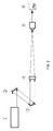
An example of the crosstalk-ratio measuring device is shown in FIG. 2. As shown in FIG. 2, the device comprises a parallel-light source 1, a two-dimensionally adjustable reflector 2, a reflector 3, and an imaging lens 4. The parallel-light source 1 is configured to emit parallel light beams, which are reflected by the two-dimensionally adjustable reflector 2 and then further reflected by the reflector 3, and then are converged by the imaging lens 4 onto a multi-pixel spot-centroid detector 5 to form a spot thereon. A position where the spot is located on the multi-pixel spot-centroid detector 5 can be adjusted by adjusting a reflecting angle of the two-dimensionally adjustable reflector 2. When the spot is located completely within the j-th pixel, signals outputted from the 1-th to l-th pixels, i.e., P1 to Pl, are recorded. The elements cij (iε[1˜l]) on the j-th column in the crosstalk matrix C can be calculated as cij=Pi/Pj. The above operations for measuring the crosstalk ratios can be repeated with respect to the respective pixels of the multi-pixel spot-centroid detector so as to derive the crosstalk matrix C.
According to embodiments of the present disclosure, there can be following advantages.
Specifically, the crosstalk matrix is adopted to characterize the crosstalk characteristics between the respective pixels of the multi-pixel spot-centroid detector. Left-multiplication of the signals outputted from the multi-pixel spot-centroid detector by the inverse matrix of the crosstalk matrix can restore the light-intensity-distribution signal with the impacts of the crosstalk substantially removed. Based on this light-intensity-distribution signal, it is possible to derive the spot centroid, with the offset in the spot centroid due to the crosstalk substantially eliminated, resulting in an improved accuracy of the spot centroid detection.
Further, there is provided an apparatus and a method of measuring crosstalk ratios between respective pixels of a multi-pixel spot-centroid detector. By means of the apparatus and the method, it is possible to measure the crosstalk ratios between the respective pixels of the multi-pixel spot-centroid detector in a simple, quick and accurate manner, so as to derive a crosstalk matrix characterizing crosstalk characteristics between the respective pixels of the multi-pixel spot-centroid detector.
BRIEF DESCRIPTION OF THE DRAWINGS
FIG. 1 is a flowchart showing a method of eliminating an offset in a spot centroid due to crosstalk according to an embodiment of the present disclosure;
FIG. 2 is a structural diagram showing an apparatus for measuring inter-pixel crosstalk of a multi-pixel spot-centroid detector according to an embodiment of the present disclosure;
FIG. 3 is a schematic view showing an arrangement of pixels and numbering of the pixels according to an embodiment of the present disclosure;
FIG. 4 is a diagram showing a crosstalk matrix according to an embodiment of the present disclosure;
FIG. 5 shows a spot diagram with crosstalk superimposed (on the left side) and a spot diagram with crosstalk removed (on the right side), respectively, according to an embodiment of the present disclosure; and
FIG. 6 shows graphs illustrating spot-centroid positions before and after crosstalk is removed (on the left side) and graphs illustrating errors in spot-centroid detection before and after crosstalk is removed, respectively, according to an embodiment of the present disclosure.
DETAILED DESCRIPTION
A multi-pixel spot-centroid detector manufactured by existing manufacture processes, such as one indicated by 5 in the drawings, may have inter-pixel crosstalk. As a result, calculation of a spot centroid directly from signals outputted from the multi-pixel spot-centroid detector 5 will cause a significant offset error. According to embodiments of the present disclosure, a crosstalk matrix is adopted to characterize crosstalk characteristics between respective pixels of the multi-pixel spot-centroid detector 5. Specifically, crosstalk ratios between the respective pixels of the multi-pixel spot-centroid detector 5 can be measured by an inter-pixel crosstalk-ratio measuring device, and all the measured crosstalk ratios between the respective pixels then can be arranged into the crosstalk matrix. Thus, the signals outputted from the multi-pixel spot-centroid detector 5 can be left-multiplied by an inverse matrix of the crosstalk matrix to obtain output signals with the crosstalk substantially removed, which are in turn used to calculate a position of the spot centroid.
In an example, the multi-pixel spot-centroid detector 5 has its pixels arranged in an array of 20×20. In such a case, the inventive method can be implemented as follows.
(1) The pixels of the multi-pixel spot-centroid detector 5 can be numbered from 1 to 400, as shown in FIG. 3.
(2) A reflecting angle of the two-dimensionally adjustable reflector 2 can be adjusted so that a spot converged by the imaging lens 4 is concentrated completely within the pixel numbered 1 (the converged spot may have a Gaussian width <⅓ times a size of the pixel).
(3) Signals outputted from the 20×20 pixels of the multi-pixel spot-centroid detector 5 can be recorded by a computer 6, and then can be arranged in an order in which the pixels of the multi-pixel spot-centroid detector 5 are numbered, to derive a vector a1=k1·[s(1,1), s(1,2), s(1,3) . . . s(1,400)], where s(i,j) denotes an output value from a j-th pixel when the spot is located within a i-th pixel, and k1=1/s(1,1).
(4) Operations of (2) and (3) can be repeated for the remaining pixels. Specifically, the reflecting angle of the two-dimensionally adjustable reflector 2 can be adjusted gradually so that the spot converged by the imaging lens 4 scans from the 1-numbered pixel to the 400-numbered pixel. The computer 6 records signals outputted from the multi-pixel spot-centroid detector 5 to derive vectors a1 to a400 , where ki assumes a value of 1/s(i,i).
(5) A crosstalk matrix of the multi-pixel spot-centroid detector 5 can be calculated as C=[a′1 a′2 . . . a′400], where “′” denotes transpose of a matrix. The crosstalk matrix has a size of 400×400. An example diagram of the crosstalk matrix is shown in FIG. 4. From the diagram, it can be seen that the smaller is the spatial distance between the pixels, the more significant is the crosstalk and thus the greater is the crosstalk ratio therebetween.
(6) An inverse matrix D of the crosstalk matrix C can be calculated.
(7) Spot-centroid detection is carried out by the multi-pixel spot-centroid detector 5, to obtain an array of output signals with the crosstalk superimposed (as shown on the left side in FIG. 5). The output signals in the array can be numbered from 1 to 400 in the manner as shown in FIG. 3, to derive a vector E=[e1, e2, . . . e400]′, where ei indicates a value outputted from the i-th pixel, and “′” indicates transpose of a matrix.
(8) The vector E can be left-multiplied by the inverse matrix D of the crosstalk matrix, to derive a signal vector Ea with the crosstalk substantially removed. That is,
E a =D*E.
(9) The signal vector Ea with the crosstalk substantially removed can be rearranged into an m×n array of spot signals in the manner of numbering shown in FIG. 3, to derive an array of spot signals, Em, with the crosstalk substantially removed, as shown on the right side of FIG. 5.
(10) The spot centroid can be calculated based on the array of spot signals with the crosstalk substantially removed in accordance with, for example, the following equation:
x c = j = 1 n i = 1 m [ j · E m ( i , j ) ] i = 1 m j = 1 n E m ( i , j ) , y c = i = 1 m j = 1 n [ i · E m ( i , j ) ] i = 1 m j = 1 n E m ( i , j ) .
FIG. 6 shows, on the left side, graphs illustrating spot-centroid positions before and after the crosstalk is removed, respectively. Obviously, the graph illustrating the spot-centroid positions before the crosstalk is removed is gentler, indicating that the crosstalk significantly impacts the positional sensitivity of the multi-pixel spot-centroid detector 5 and thus causes offset errors of the spot centroid. FIG. 6 shows, on the right side, graphs illustrating errors in the spot-centroid detection before and after the crosstalk is removed, respectively. Obviously, the errors in the spot-centroid detection before the crosstalk is removed increase as the spot centroid is more distant from a central position of the multi-pixel spot-centroid detector 5. In contrast, the errors in the spot-centroid detection after the crosstalk is removed exhibit only fluctuations due to noises.
As can be seen from FIG. 6, the method according to the present disclosure enables substantial elimination of the offset errors of the spot centroid due to the inter-pixel crosstalk of the multi-pixel spot-centroid detector 5, resulting in an improved accuracy in the spot-centroid detection.
Those means well known to those skilled in the art are not described in detail in the present disclosure.
From the foregoing, it will be appreciated that specific embodiments of the disclosure have been described herein for purposes of illustration, but that various modifications and alternations may be made by those skilled in the art without deviating from the disclosure. All these modifications and alternations fall in the scope of the present disclosure.

Claims (1)

The invention claimed is:
1. A method of eliminating an offset in a spot centroid due to crosstalk, comprising:
measuring crosstalk ratios between respective pixels of a detector by a crosstalk-ratio measuring device;
arranging the crosstalk ratios between the respective pixels into a crosstalk matrix characterizing crosstalk characteristics of the detector;
left-multiplying signals outputted from the detector by an inverse matrix of the crosstalk matrix to derive a light-intensity-distribution signal with impacts of the crosstalk substantially removed; and
calculating the spot centroid based on the light-intensity-distribution signal,
wherein the crosstalk-ratio measuring device comprises:
a parallel-light source configured to emit parallel light beams;
a two-dimensionally adjustable reflector configured to reflect the parallel light beams from the parallel-light source;
a reflector configured to further reflect the light beams reflected by the two-dimensionally adjustable reflector;
an imaging lens configured to converge the light beams reflected by the reflector onto the multi-pixel spot-centroid detector to form a spot thereon;
a computer configured to record signals outputted from the multi-pixel spot-centroid detector; and
wherein measuring the crosstalk ratios comprises:
numbering the pixels of the detector from 1 to l, where l=m×n indicates a total number of the pixels of the detector; and
measuring the crosstalk ratio cij between every two pixels,
arranging the crosstalk ratios into the crosstalk matrix comprises:
arranging all the measured crosstalk ratios into a matrix as follows:
C = [ 1 c 12 c 13 c 1 l c 21 1 c 23 c 2 l c 31 c 32 1 c 3 l c l 1 c l 2 c l 3 1 ] ,
 wherein an element cij in the crosstalk matrix C has a physical meaning that a true signal Pj arriving at a j-th pixel will cause a dummy signal of cij·Pj at a i-th pixel due to the crosstalk, and
wherein measuring the crosstalk ratios comprises:
adjusting a reflecting angle of the two-dimensionally adjustable reflector to adjust a position where the spot is located on the multi-pixel spot-centroid detector;
recording signals outputted from the 1-th to l-th pixels of the multi-pixel spot-centroid detector, i.e., P1 to Pl, when the spot is located completely within the j-th pixel;
calculating the elements cij on the j-th column in the crosstalk matrix C as cij=Pi/Pj, where iε[1˜l]; and
repeatedly performing above operations with respect to the respective pixels of the multi-pixel spot-centroid detector so as to derive the crosstalk matrix C.
US13/965,891 2012-08-14 2013-08-13 Method of eliminating offset in spot centroid due to crosstalk Expired - Fee Related US9236943B2 (en)

Applications Claiming Priority (3)

Application Number Priority Date Filing Date Title
CN201210288531.6A CN102798849B (en) 2012-08-14 2012-08-14 Method for eliminating spot centroid shift due to crosstalk
CN201210288531.6 2012-08-14
CN201210288531 2012-08-14

Publications (2)

Publication Number Publication Date
US20140178078A1 US20140178078A1 (en) 2014-06-26
US9236943B2 true US9236943B2 (en) 2016-01-12

Family

ID=47198007

Family Applications (1)

Application Number Title Priority Date Filing Date
US13/965,891 Expired - Fee Related US9236943B2 (en) 2012-08-14 2013-08-13 Method of eliminating offset in spot centroid due to crosstalk

Country Status (4)

Country Link
US (1) US9236943B2 (en)
JP (1) JP5666663B2 (en)
CN (1) CN102798849B (en)
DE (1) DE102013108788B4 (en)

Cited By (3)

* Cited by examiner, † Cited by third party
Publication number Priority date Publication date Assignee Title
US20150222357A1 (en) * 2012-10-19 2015-08-06 Fraunhofer-Gesellschaft Zur Foerderung Der Angewandten Forschung E.V. Apparatus and method for retrieveing data from a wdm signal, transmitter and method for transmitting a wdm signal, and wdm system
US20160065925A1 (en) * 2013-05-13 2016-03-03 Fujifilm Corporation Color-mixture-ratio calculation device and method, and imaging device
US9755738B2 (en) * 2013-03-20 2017-09-05 Nistica, Inc. Crosstalk suppression in a multi-photodetector optical channel monitor

Families Citing this family (7)

* Cited by examiner, † Cited by third party
Publication number Priority date Publication date Assignee Title
DE102016118638A1 (en) * 2016-09-30 2018-04-19 Jenoptik Advanced Systems Gmbh Method and thermal imaging camera for non-contact temperature measurement or observation of fast-moving IR scenes with a thermal IR image sensor
US10305604B1 (en) * 2017-12-28 2019-05-28 Facebook, Inc. Coherent aperture combining using machine learning
CN109150301B (en) * 2018-07-13 2020-06-19 中国船舶重工集团公司第七一九研究所 Light spot capturing system and method based on CMOS image sensor
KR20200067020A (en) * 2018-12-03 2020-06-11 삼성전자주식회사 Method and apparatus for calibration
JP7442376B2 (en) * 2020-04-06 2024-03-04 株式会社ニューフレアテクノロジー Multi-electron beam inspection device and multi-electron beam inspection method
CN114046731B (en) * 2021-10-29 2023-03-14 西安工程大学 Submicron single photon magnitude tiny light spot measuring method based on silicon photomultiplier
WO2024054511A1 (en) * 2022-09-07 2024-03-14 ams Sensors USA Inc. Image sensor and method of generating an image signal

Citations (13)

* Cited by examiner, † Cited by third party
Publication number Priority date Publication date Assignee Title
US5448053A (en) * 1993-03-01 1995-09-05 Rhoads; Geoffrey B. Method and apparatus for wide field distortion-compensated imaging
JPH1051603A (en) * 1996-08-02 1998-02-20 Canon Inc Image reader
US6005916A (en) * 1992-10-14 1999-12-21 Techniscan, Inc. Apparatus and method for imaging with wavefields using inverse scattering techniques
US6347001B1 (en) * 1998-11-03 2002-02-12 Trex Communications Corporation Free-space laser communication system having six axes of movement
JP2004336339A (en) * 2003-05-07 2004-11-25 Nippon Hoso Kyokai <Nhk> Image pickup device
US20050142033A1 (en) * 2003-11-04 2005-06-30 Meso Scale Technologies, Llc. Modular assay plates, reader systems and methods for test measurements
US20060024061A1 (en) * 2004-02-12 2006-02-02 Adaptive Optics Associates, Inc. Wavefront sensing system employing active updating of reference positions and subaperture locations on wavefront sensor
US20070057211A1 (en) * 2005-05-25 2007-03-15 Karsten Bahlman Multifocal imaging systems and method
US20080008472A1 (en) * 2002-11-05 2008-01-10 Dress William B Distribution optical elements and compound collecting lenses for broadcast optical interconnect
US20110031418A1 (en) * 2007-10-31 2011-02-10 Ben Gurion Univesity of the Negev Research and Development Authority Optical sensor measurement and crosstalk evaluation
US20110069960A1 (en) * 2008-09-05 2011-03-24 Knapp David J Systems and methods for visible light communication
US20120206635A1 (en) * 2011-02-14 2012-08-16 Sony Corporation Image processing apparatus, image processing method and electronic equipment
US20140152986A1 (en) * 2004-03-06 2014-06-05 Michael Trainer Methods and apparatus for determining characteristics of particles

Family Cites Families (9)

* Cited by examiner, † Cited by third party
Publication number Priority date Publication date Assignee Title
JPS63304113A (en) * 1987-06-04 1988-12-12 Nec Corp Star sensor
JP2680331B2 (en) * 1988-03-17 1997-11-19 株式会社東芝 Spacecraft capture and tracking device
JPH02147883A (en) * 1988-11-29 1990-06-06 Hitachi Ltd Multichannel radiation detecting device
JP2720843B2 (en) * 1995-08-15 1998-03-04 日本電気株式会社 Emission center position detection device
JP4598554B2 (en) * 2005-02-09 2010-12-15 浜松ホトニクス株式会社 Photodetector
JP2006239118A (en) * 2005-03-03 2006-09-14 Ge Medical Systems Global Technology Co Llc X-ray ct system
JP5735803B2 (en) * 2007-08-23 2015-06-17 スリーディー システムズ インコーポレーテッド Automatic shape calibration method using laser scanning reflectometer
WO2009094618A1 (en) * 2008-01-25 2009-07-30 President And Fellows Of Harvard College System and method for cross-talk correction
CN101408985B (en) * 2008-09-22 2010-09-22 北京航空航天大学 Method and apparatus for extracting circular luminous spot second-pixel center

Patent Citations (13)

* Cited by examiner, † Cited by third party
Publication number Priority date Publication date Assignee Title
US6005916A (en) * 1992-10-14 1999-12-21 Techniscan, Inc. Apparatus and method for imaging with wavefields using inverse scattering techniques
US5448053A (en) * 1993-03-01 1995-09-05 Rhoads; Geoffrey B. Method and apparatus for wide field distortion-compensated imaging
JPH1051603A (en) * 1996-08-02 1998-02-20 Canon Inc Image reader
US6347001B1 (en) * 1998-11-03 2002-02-12 Trex Communications Corporation Free-space laser communication system having six axes of movement
US20080008472A1 (en) * 2002-11-05 2008-01-10 Dress William B Distribution optical elements and compound collecting lenses for broadcast optical interconnect
JP2004336339A (en) * 2003-05-07 2004-11-25 Nippon Hoso Kyokai <Nhk> Image pickup device
US20050142033A1 (en) * 2003-11-04 2005-06-30 Meso Scale Technologies, Llc. Modular assay plates, reader systems and methods for test measurements
US20060024061A1 (en) * 2004-02-12 2006-02-02 Adaptive Optics Associates, Inc. Wavefront sensing system employing active updating of reference positions and subaperture locations on wavefront sensor
US20140152986A1 (en) * 2004-03-06 2014-06-05 Michael Trainer Methods and apparatus for determining characteristics of particles
US20070057211A1 (en) * 2005-05-25 2007-03-15 Karsten Bahlman Multifocal imaging systems and method
US20110031418A1 (en) * 2007-10-31 2011-02-10 Ben Gurion Univesity of the Negev Research and Development Authority Optical sensor measurement and crosstalk evaluation
US20110069960A1 (en) * 2008-09-05 2011-03-24 Knapp David J Systems and methods for visible light communication
US20120206635A1 (en) * 2011-02-14 2012-08-16 Sony Corporation Image processing apparatus, image processing method and electronic equipment

Non-Patent Citations (3)

* Cited by examiner, † Cited by third party
Title
Xia, J.; "Design of an Optical Collimation and Automatic Tracking System;" Electronics Optics & Control, 2009, 16(5), 74-77; abstract retrieved on Sep. 17, 2013 from .
Xia, J.; "Design of an Optical Collimation and Automatic Tracking System;" Electronics Optics & Control, 2009, 16(5), 74-77; abstract retrieved on Sep. 17, 2013 from <http://en.cnki.com.cn/Article-en/CJFDTOTAL-DGKQ200905019.htm>.
Xiaofeng, L., et al., "Effect of Background Light and Atmospheric Turbulence to Spots Received in Space-to-Ground Laser Communications;" Wireless Optical Communications, 2004(10), 22-24.

Cited By (5)

* Cited by examiner, † Cited by third party
Publication number Priority date Publication date Assignee Title
US20150222357A1 (en) * 2012-10-19 2015-08-06 Fraunhofer-Gesellschaft Zur Foerderung Der Angewandten Forschung E.V. Apparatus and method for retrieveing data from a wdm signal, transmitter and method for transmitting a wdm signal, and wdm system
US9503187B2 (en) * 2012-10-19 2016-11-22 Fraunhofer-Gesellschaft Zur Foerderung Der Angewandten Forschung E.V. Apparatus and method for retrieving data from a WDM signal, transmitter and method for transmitting a WDM signal, and WDM system
US9755738B2 (en) * 2013-03-20 2017-09-05 Nistica, Inc. Crosstalk suppression in a multi-photodetector optical channel monitor
US20160065925A1 (en) * 2013-05-13 2016-03-03 Fujifilm Corporation Color-mixture-ratio calculation device and method, and imaging device
US9877004B2 (en) * 2013-05-13 2018-01-23 Fujifilm Corporation Color-mixture-ratio calculation device and method, and imaging device

Also Published As

Publication number Publication date
CN102798849A (en) 2012-11-28
JP2014059295A (en) 2014-04-03
DE102013108788B4 (en) 2016-11-03
JP5666663B2 (en) 2015-02-12
DE102013108788A1 (en) 2014-02-20
CN102798849B (en) 2014-03-26
US20140178078A1 (en) 2014-06-26

Similar Documents

Publication Publication Date Title
US9236943B2 (en) Method of eliminating offset in spot centroid due to crosstalk
CN101672642B (en) Optical precision tracking detector based on double pyramidal rectangular pyramids
CN103308187B (en) High frequency three dimensional Shack Hartmann wavefront measuring device and measuring method thereof
US7212938B2 (en) Method of using a self-locking travel pattern to achieve calibration of remote sensors using conventionally collected data
CN103760567A (en) Passive imaging system with distance measuring function and distance measuring method thereof
US20170261623A1 (en) High speed gamma imaging device
KR20190002013U (en) LiDAR device
CN103345145B (en) A kind of method utilizing laser to carry out spaceborne clock measurement
Srinivasan et al. Photon counting detector array algorithms for deep space optical communications
CN103792526A (en) Laser ceilometer dynamic threshold selecting method based on pulse echo forms
CN101672641B (en) Optical precision tracking detector based on double four quadrant photoelectric detectors
Huikari et al. Compact laser radar based on a subnanosecond laser diode transmitter and a two-dimensional CMOS single-photon receiver
Jeong et al. UBAT of UFFO/Lomonosov: The X-ray space telescope to observe early photons from gamma-ray bursts
CN110018493B (en) Laser power selection method of dual-waveband intersection type active range gating imaging system
Pierrottet et al. Characterization of 3-D imaging lidar for hazard avoidance and autonomous landing on the Moon
Cortina et al. First measurements and upgrade plans of the MAGIC intensity interferometer
Alerstam et al. The effect of photon counting detector blocking on centroiding for deep space optical communications
CN115932888A (en) High-resolution space target three-dimensional detection system
CN108981749A (en) X-ray pulsar angular position measurement ground simulation verifies system and its application method
CN114413750A (en) Positioning sensor, positioning system and positioning method based on laser scattering light spots
Ogawa et al. Observation of optical transients and search for PEV-EEV tau neutrinos with ASHRA-1
US20050169646A1 (en) Lincoln distributed optical receiver array
Morcuende Parrilla Study of the performance of the first Large-Sized Cherenkov telescope of CTA, the relevance of fluorescence in the Cherenkov technique and the multiwavelength emission from the blazar 1ES 0647+ 250
Weinfurther Designing an Optically Segmented Single-Volume Neutron Scatter Camera Using Simulation and Experimental Validation
Pawlikowska Single-photon counting LiDAR for long-range three-dimensional imaging

Legal Events

Date Code Title Description
AS Assignment

Owner name: THE INSTITUTE OF OPTICS AND ELECTRONICS, THE CHINE

Free format text: ASSIGNMENT OF ASSIGNORS INTEREST;ASSIGNORS:MA, XIAOYU;RAO, CHANGHUI;WEI, KAI;REEL/FRAME:031650/0558

Effective date: 20131112

STCF Information on status: patent grant

Free format text: PATENTED CASE

MAFP Maintenance fee payment

Free format text: PAYMENT OF MAINTENANCE FEE, 4TH YR, SMALL ENTITY (ORIGINAL EVENT CODE: M2551); ENTITY STATUS OF PATENT OWNER: SMALL ENTITY

Year of fee payment: 4

FEPP Fee payment procedure

Free format text: MAINTENANCE FEE REMINDER MAILED (ORIGINAL EVENT CODE: REM.); ENTITY STATUS OF PATENT OWNER: SMALL ENTITY

LAPS Lapse for failure to pay maintenance fees

Free format text: PATENT EXPIRED FOR FAILURE TO PAY MAINTENANCE FEES (ORIGINAL EVENT CODE: EXP.); ENTITY STATUS OF PATENT OWNER: SMALL ENTITY

STCH Information on status: patent discontinuation

Free format text: PATENT EXPIRED DUE TO NONPAYMENT OF MAINTENANCE FEES UNDER 37 CFR 1.362

FP Lapsed due to failure to pay maintenance fee

Effective date: 20240112