US9237838B2 - Endoscopy system and a pressure transmitting connector for said system - Google Patents
Endoscopy system and a pressure transmitting connector for said system Download PDFInfo
- Publication number
- US9237838B2 US9237838B2 US13/656,394 US201213656394A US9237838B2 US 9237838 B2 US9237838 B2 US 9237838B2 US 201213656394 A US201213656394 A US 201213656394A US 9237838 B2 US9237838 B2 US 9237838B2
- Authority
- US
- United States
- Prior art keywords
- channel
- communication
- fluid communication
- blind
- membrane
- Prior art date
- Legal status (The legal status is an assumption and is not a legal conclusion. Google has not performed a legal analysis and makes no representation as to the accuracy of the status listed.)
- Active, expires
Links
Images


Classifications
-
- A—HUMAN NECESSITIES
- A61—MEDICAL OR VETERINARY SCIENCE; HYGIENE
- A61B—DIAGNOSIS; SURGERY; IDENTIFICATION
- A61B1/00—Instruments for performing medical examinations of the interior of cavities or tubes of the body by visual or photographical inspection, e.g. endoscopes; Illuminating arrangements therefor
- A61B1/012—Instruments for performing medical examinations of the interior of cavities or tubes of the body by visual or photographical inspection, e.g. endoscopes; Illuminating arrangements therefor characterised by internal passages or accessories therefor
- A61B1/015—Control of fluid supply or evacuation
-
- A—HUMAN NECESSITIES
- A61—MEDICAL OR VETERINARY SCIENCE; HYGIENE
- A61B—DIAGNOSIS; SURGERY; IDENTIFICATION
- A61B1/00—Instruments for performing medical examinations of the interior of cavities or tubes of the body by visual or photographical inspection, e.g. endoscopes; Illuminating arrangements therefor
- A61B1/12—Instruments for performing medical examinations of the interior of cavities or tubes of the body by visual or photographical inspection, e.g. endoscopes; Illuminating arrangements therefor with cooling or rinsing arrangements
-
- A—HUMAN NECESSITIES
- A61—MEDICAL OR VETERINARY SCIENCE; HYGIENE
- A61B—DIAGNOSIS; SURGERY; IDENTIFICATION
- A61B1/00—Instruments for performing medical examinations of the interior of cavities or tubes of the body by visual or photographical inspection, e.g. endoscopes; Illuminating arrangements therefor
- A61B1/313—Instruments for performing medical examinations of the interior of cavities or tubes of the body by visual or photographical inspection, e.g. endoscopes; Illuminating arrangements therefor for introducing through surgical openings, e.g. laparoscopes
- A61B1/317—Instruments for performing medical examinations of the interior of cavities or tubes of the body by visual or photographical inspection, e.g. endoscopes; Illuminating arrangements therefor for introducing through surgical openings, e.g. laparoscopes for bones or joints, e.g. osteoscopes, arthroscopes
Definitions
- the invention relates to an endoscopy system comprising more particularly a cannula for housing an endoscope and for forming, between the cannula and the endoscope, an irrigation channel or an outflow channel, and including a coupling ring mounted around the cannula and provided with a coupling path for communicating with the irrigation or outflow channel.
- Such an endoscopy system is described for example by the documents U.S. Pat. No. 5,037,386 and U.S. Pat. No. 6,086,542. It is used in joint arthroscopy, and more particularly in knee arthroscopy.
- the endoscope is connected to a video screen for displaying the joint.
- the irrigation or outflow channel makes it possible to create a circulation of physiological saline for keeping the medium in front of the endoscope optically clear and for bathing the joint.
- the circulation is provided by a pump connected to a reservoir and outputting into a tubing connected to the irrigation channel or to the outflow channel via the coupling ring.
- the pressure of the physiological saline in the joint is monitored by a membrane pressure sensor placed in the tubing of the irrigation channel or the outflow channel, or on a tubing connected via the coupling ring to a channel formed in the cannula and dedicated to pressure sensing, as in the case of the endoscopy systems described by the abovementioned documents.
- a membrane pressure sensor placed in the tubing of the irrigation channel or the outflow channel, or on a tubing connected via the coupling ring to a channel formed in the cannula and dedicated to pressure sensing, as in the case of the endoscopy systems described by the abovementioned documents.
- the extrapolation of the pressure in the joint from the pressure sensed in the communication path of the connector makes it possible to dispense with a dedicated pressure-sensing channel in the cannula.
- the diameter of the cannula is decreased, for the purpose of reducing the trauma when it is being introduced into the joint.
- the connector thus eliminates the risk of a variation in cross section of the communication path and allows reliable sensing of the pressure in this communication path.
- the sensed pressure remains subject to an artificially high pressure drop in the coupling path for coupling the communication path of the connector to the irrigation channel of the cannula. This may be due to a foreign body present in the coupling path of the coupling ring and partially obstructing the flow of physiological saline in the irrigation channel.
- One of the objects of the invention is to elevate this drawback so as to confer a high degree of safety on the endoscopy system.
- the subject of the invention is an endoscopy system comprising a cannula for housing an endoscope and for forming, between the cannula and the endoscope, an irrigation channel and outflow channel respectively, intended for transporting an irrigation fluid and outflow fluid respectively, a coupling ring mounted around the cannula and provided with a coupling path for coupling to the irrigation channel, and to the outflow channel respectively, and a connector mounted on the coupling ring and comprising a communication path for communicating with the coupling path and a first pressure sensor for sensing the pressure in the communication path, characterized in that the coupling ring is provided with a branch-off path that communicates with the irrigation channel, and with the outflow channel respectively, and in that the connector includes a blind path communicating with the branch-off path and a second pressure sensor for sensing the pressure in this blind path.
- the branch-off path of the coupling ring communicates with the blind path of the connector in order for the pressure of the fresh physiological saline flowing in the irrigation channel to be sensed a second time.
- the branch-off path is placed downstream of the coupling path for coupling to the irrigation channel relative to the transport of the irrigating fluid and upstream of the coupling path for coupling to the outflow channel, respectively, relative to the transport of the outflow fluid, and in that an irrigation tap is provided for closing or opening the coupling path to the irrigation channel, upstream of the branch-off path, and an outflow tap is provided for closing or opening the coupling path to the outflow channel, respectively, downstream of the branch-off path.
- this arrangement makes it possible for the pressure in the joint to be always checked, even when the flow of the fresh physiological saline in the irrigation channel is interrupted by closing the irrigation tap. The same applies when the soiled physiological saline flowing in the outflow channel is considered.
- the invention extends to a connector intended for an endoscopy system comprising a communication path and a pressure sensor for sensing the pressure in this communication path, characterized in that it includes a blind path and a second pressure sensor for sensing the pressure in the blind path.
- the connector includes a second communication path.
- the branch-off path is placed between the two communication paths. This arrangement makes it possible to connect the coupling ring to the communication path for irrigation, to the blind path and to the communication path for the outflow in a single operation, while still allowing pressure sensing in the blind path and one or other of the communication paths.
- FIG. 1 shows an endoscopy system in front view.
- FIG. 2 shows the endoscopy system of FIG. 1 in top view.
- FIG. 3 shows the endoscopy system of FIG. 1 in longitudinal section.
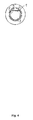
- FIG. 4 shows the endoscopy system of FIG. 1 in cross section.
- FIG. 5 shows, in cross section, a first connector intended for an endoscopy system according to the invention.
- FIG. 6 shows, in cross section, a second connector intended for an endoscopy system according to the invention.
- An endoscopy system comprises ( FIGS. 1 to 4 ) a cannula 1 for housing an endoscope 3 and for forming, between the cannula 1 and the endoscope 3 , an irrigation channel 5 .
- the irrigation channel 5 is formed between the endoscope 3 and a tube 7 internal to the cannula 1
- an outflow channel 9 is formed between the internal tube 7 and the cannula 1 .
- the invention also applies to a cannula having only the irrigation channel or only the outflow channel.
- a coupling ring 11 is mounted around the cannula 1 in order to communicate with the irrigation channel 5 and the outflow channel 9 .
- a first coupling path 13 communicates with the irrigation channel 5 .
- a second coupling path 15 communicates with the outflow channel 9 .
- a connector 17 is mounted on the coupling ring 11 . It comprises a first communication path 19 , for communicating with the first coupling path 13 for coupling to the irrigation channel 5 and a first sensor 18 a , and comprises a second communication path 21 for communicating with the second coupling path 15 for coupling to the outflow channel 9 .
- the two communication paths 19 and 21 of the connector 17 are placed facing the first pressure sensor 18 a for sensing the pressure in one or other ( 19 or 21 ) of these two communication paths.
- Tubings (not shown) are connected to the communication paths 19 and 21 of the connector 17 and are connected to a pump in order to create a flow of fresh physiological saline in the irrigation channel 5 and of soiled physiological saline in the outflow channel 9 .
- the coupling ring 11 includes, in a manner known per se, taps 23 and 25 for opening or closing the coupling paths 13 and 15 according to the desired flow in the irrigation channel 5 or in the outflow channel 9 .
- the connector 17 is mounted on the coupling ring 11 in order to allow the irrigation channel 5 and the outflow channel 9 to communicate with the two communication paths 13 and 15 of the connector without the intermediary of a tubing. With this arrangement, the pressure sensed in one or other of the communication paths of the connector is not subject to an error due to an accidental variation in the cross section of the tubings that would be connected to the coupling paths of the coupling ring.
- the coupling ring 11 includes a branch-off path 27 for communicating with the coupling path 13 for coupling to the irrigation channel 5
- the connector 17 includes a blind path 29 for communicating with the branch-off path 27 and the second pressure sensor 18 b for sensing the pressure in this blind path.
- the branch-off path 27 of the coupling ring communicates with the blind path 29 of the connector in order to allow the pressure of the fresh physiological saline flowing in the irrigation channel to be detected a second time.
- the branch-off path 27 is placed, relative to the transport of the irrigated fluid, downstream of the coupling path 13 for coupling to the irrigation channel 5 , and the irrigation tap 23 is designed to close or open this coupling path 13 upstream of the branch-off path 27 .
- the branch-off path 27 is placed, relative to the transport of the outflow fluid, upstream of the coupling path 15 for coupling to the outflow channel 9 , and the outflow tap 25 is designed to close or open this coupling path 15 downstream of the branch-off path 27 .
- This arrangement makes it possible advantageously to detect the pressure in one channel—the branch-off path—undisturbed at the opening or closing, even if partial, of the tap 23 of the coupling path 13 for coupling to the irrigation channel 5 , or of the tap 25 of the coupling path 15 for coupling to the outflow channel 9 .
- the pressure in the joint may be extrapolated by means of the branch-off path, even when the flow of physiological saline is interrupted in the irrigation channel, or the outflow channel respectively, by closing the irrigation tap 23 , or the outflow tap 25 , respectively.
- the second pressure sensing via the blind path allows the integrity of the endoscopy system according to the invention to be better checked compared with the pressures sensed by the two detectors with expected values.
- it is possible to diagnose a fault in the irrigation tap 23 by an abnormal pressure drop between the pressure sensed by the first detector 18 a in the communication path 19 for communicating with the irrigation channel 5 and the pressure sensed by the second detector 18 b in the blind path.
- the connector of the endoscopy system is preferably a rigid part made of an injection molded plastic and incorporates two membrane pressure sensors 18 a and 18 b .
- the first sensor 18 a and the second sensor 18 b each comprise a chamber 35 a , 35 b and a membrane 37 a , 37 b designed to be deformed and to cause the air pressure in the chamber 35 a , 35 b to vary.
- the communication path 19 , 21 , the duct 41 a , 41 b and the fluid compartment 39 a , 39 b are formed in one and the same rigid part 43 to which the membrane 37 a , 37 b and the transmission chamber are connected in order to close off the transmission chamber on the fluid compartment 39 a , 39 b via the membrane 37 a , 37 b .
- the rigid part 43 is provided with means 31 for fastening it to the coupling ring 11 .
- the rigid part 43 is provided with a polarizing feature, for polarizing the connection on the coupling ring 11 .
- the physiological saline flowing in the communication path 19 for communicating with the irrigation channel 5 ( FIG. 5 ) or in the communication path 21 for communicating with the outflow channel 9 ( FIG. 6 ) enters the fluid compartment 39 a of the first pressure sensor 18 a , which is open to the communication path 13 , 15 via the duct 41 a and closed by the membrane 37 a .
- This membrane 37 a deforms according to the pressure of the physiological saline in the communication path 19 or 21 .
- the physiological saline flowing in the irrigation channel 5 and the outflow channel 9 enters, via the branch-off path 27 and the blind path 29 , into the fluid compartment 39 b of the second detector 18 b , which is open to the blind path 29 via the duct 41 b and closed by the membrane 37 b .
- the latter deforms according to the pressure of the physiological saline in the blind path 29 .
- Capillaries (not shown) are connected to connection points 47 on the transmission chambers 35 a , 35 b in order to transmit the variations in the air pressure inside the chambers 35 a , 35 b to sensors (not shown) and for determining the pressure of the physiological saline in the communication path 19 , 21 and in the blind path 29 .
- the endoscopy system according to the invention is particularly useful in the arthroscopy of joints, such as the knee or the shoulder.
- the invention applies to a cannula that does not have a channel dedicated to sensing the pressure in the joint, so as advantageously to decrease the outside diameter of the cannula, in order to make it less traumatic when being inserted by the surgeon.
- the invention also applies to an endoscopy system in which the cannula does include a channel dedicated to measuring the pressure.
- the coupling ring is therefore modified so that the branch-off path communicates with the pressure dedicated channel and the connector is mounted on the coupling ring in order to bring the blind path into communication with the branch-off path.
Abstract
The inventive endoscopy system includes a cannula for arranging an endoscope and forming, between said cannula and endoscope, an irrigation or aspiration channel for transporting an irrigation or aspiration fluid, respectively, a connection ring mounted around the cannula and provided with a connection channel connectable to the irrigation or aspiration channel, respectively and a connector which is mounted on the connection ring and includes a transport channel with the connection channel and a first pressure sensor for detecting pressure in the transport channel. The connection ring is provided with a bypass circuit connectable to the irrigation or aspiration channel, respectively and the connector including a dead channel connectable to the bypass circuit and a second pressure sensor for detecting pressure in the dead channel.
Description
This application is a continuation of application Ser. No. 13/005,908 filed Jan. 13, 2011, which is a continuation of application Ser. No. 10/591,441 filed Dec. 21, 2006, which is a national stage of PCT/CH2005/000122 filed Mar. 2, 2005, each of which is hereby incorporated herein in its entirety.
The invention relates to an endoscopy system comprising more particularly a cannula for housing an endoscope and for forming, between the cannula and the endoscope, an irrigation channel or an outflow channel, and including a coupling ring mounted around the cannula and provided with a coupling path for communicating with the irrigation or outflow channel.
Such an endoscopy system is described for example by the documents U.S. Pat. No. 5,037,386 and U.S. Pat. No. 6,086,542. It is used in joint arthroscopy, and more particularly in knee arthroscopy. The endoscope is connected to a video screen for displaying the joint. The irrigation or outflow channel makes it possible to create a circulation of physiological saline for keeping the medium in front of the endoscope optically clear and for bathing the joint. The circulation is provided by a pump connected to a reservoir and outputting into a tubing connected to the irrigation channel or to the outflow channel via the coupling ring.
The pressure of the physiological saline in the joint is monitored by a membrane pressure sensor placed in the tubing of the irrigation channel or the outflow channel, or on a tubing connected via the coupling ring to a channel formed in the cannula and dedicated to pressure sensing, as in the case of the endoscopy systems described by the abovementioned documents. These arrangements have the drawback of resulting in the pressure being erroneously determined under certain operating conditions, for example should by accident there be a sharp bend between the pressure sensor and the coupling ring.
Document U.S. Pat. No. 5,643,203 discloses an endoscopy system of the type mentioned above, in which a connector is mounted on the coupling ring and includes a communication path for communicating with the irrigation channel and a pressure sensor for sensing the pressure in the communication path. The pressure of the physiological saline in the joint is extrapolated from a law, on the basis of the pressure sensed in the communication path.
The extrapolation of the pressure in the joint from the pressure sensed in the communication path of the connector makes it possible to dispense with a dedicated pressure-sensing channel in the cannula. Thus, it is possible for the diameter of the cannula to be decreased, for the purpose of reducing the trauma when it is being introduced into the joint. Compared to a tubing, the connector thus eliminates the risk of a variation in cross section of the communication path and allows reliable sensing of the pressure in this communication path.
However, the sensed pressure remains subject to an artificially high pressure drop in the coupling path for coupling the communication path of the connector to the irrigation channel of the cannula. This may be due to a foreign body present in the coupling path of the coupling ring and partially obstructing the flow of physiological saline in the irrigation channel.
One of the objects of the invention is to elevate this drawback so as to confer a high degree of safety on the endoscopy system.
For this purpose, the subject of the invention is an endoscopy system comprising a cannula for housing an endoscope and for forming, between the cannula and the endoscope, an irrigation channel and outflow channel respectively, intended for transporting an irrigation fluid and outflow fluid respectively, a coupling ring mounted around the cannula and provided with a coupling path for coupling to the irrigation channel, and to the outflow channel respectively, and a connector mounted on the coupling ring and comprising a communication path for communicating with the coupling path and a first pressure sensor for sensing the pressure in the communication path, characterized in that the coupling ring is provided with a branch-off path that communicates with the irrigation channel, and with the outflow channel respectively, and in that the connector includes a blind path communicating with the branch-off path and a second pressure sensor for sensing the pressure in this blind path.
The branch-off path of the coupling ring communicates with the blind path of the connector in order for the pressure of the fresh physiological saline flowing in the irrigation channel to be sensed a second time. The same applies when the soiled physiological saline flowing in the outflow channel is considered. Hence, it follows that the endoscopy system according to the invention has two safety levels for checking the pressure of the physiological saline in the joint.
Preferably, the branch-off path is placed downstream of the coupling path for coupling to the irrigation channel relative to the transport of the irrigating fluid and upstream of the coupling path for coupling to the outflow channel, respectively, relative to the transport of the outflow fluid, and in that an irrigation tap is provided for closing or opening the coupling path to the irrigation channel, upstream of the branch-off path, and an outflow tap is provided for closing or opening the coupling path to the outflow channel, respectively, downstream of the branch-off path. Advantageously, this arrangement makes it possible for the pressure in the joint to be always checked, even when the flow of the fresh physiological saline in the irrigation channel is interrupted by closing the irrigation tap. The same applies when the soiled physiological saline flowing in the outflow channel is considered.
The invention extends to a connector intended for an endoscopy system comprising a communication path and a pressure sensor for sensing the pressure in this communication path, characterized in that it includes a blind path and a second pressure sensor for sensing the pressure in the blind path.
Advantageously, the connector includes a second communication path. Preferably, the branch-off path is placed between the two communication paths. This arrangement makes it possible to connect the coupling ring to the communication path for irrigation, to the blind path and to the communication path for the outflow in a single operation, while still allowing pressure sensing in the blind path and one or other of the communication paths.
Other advantages of the invention will become apparent on the reading the description of one embodiment illustrated below by the drawings.
An endoscopy system comprises (FIGS. 1 to 4 ) a cannula 1 for housing an endoscope 3 and for forming, between the cannula 1 and the endoscope 3, an irrigation channel 5. In the embodiment chosen to illustrate the invention, the irrigation channel 5 is formed between the endoscope 3 and a tube 7 internal to the cannula 1, and an outflow channel 9 is formed between the internal tube 7 and the cannula 1. However, the invention also applies to a cannula having only the irrigation channel or only the outflow channel.
A coupling ring 11 is mounted around the cannula 1 in order to communicate with the irrigation channel 5 and the outflow channel 9. A first coupling path 13 communicates with the irrigation channel 5. A second coupling path 15 communicates with the outflow channel 9.
A connector 17 is mounted on the coupling ring 11. It comprises a first communication path 19, for communicating with the first coupling path 13 for coupling to the irrigation channel 5 and a first sensor 18 a, and comprises a second communication path 21 for communicating with the second coupling path 15 for coupling to the outflow channel 9. The two communication paths 19 and 21 of the connector 17 are placed facing the first pressure sensor 18 a for sensing the pressure in one or other (19 or 21) of these two communication paths.
Tubings (not shown) are connected to the communication paths 19 and 21 of the connector 17 and are connected to a pump in order to create a flow of fresh physiological saline in the irrigation channel 5 and of soiled physiological saline in the outflow channel 9. The coupling ring 11 includes, in a manner known per se, taps 23 and 25 for opening or closing the coupling paths 13 and 15 according to the desired flow in the irrigation channel 5 or in the outflow channel 9.
The connector 17 is mounted on the coupling ring 11 in order to allow the irrigation channel 5 and the outflow channel 9 to communicate with the two communication paths 13 and 15 of the connector without the intermediary of a tubing. With this arrangement, the pressure sensed in one or other of the communication paths of the connector is not subject to an error due to an accidental variation in the cross section of the tubings that would be connected to the coupling paths of the coupling ring.
According to the invention, the coupling ring 11 includes a branch-off path 27 for communicating with the coupling path 13 for coupling to the irrigation channel 5, whereas the connector 17 includes a blind path 29 for communicating with the branch-off path 27 and the second pressure sensor 18 b for sensing the pressure in this blind path. As indicated above, the branch-off path 27 of the coupling ring communicates with the blind path 29 of the connector in order to allow the pressure of the fresh physiological saline flowing in the irrigation channel to be detected a second time.
Preferably, the branch-off path 27 is placed, relative to the transport of the irrigated fluid, downstream of the coupling path 13 for coupling to the irrigation channel 5, and the irrigation tap 23 is designed to close or open this coupling path 13 upstream of the branch-off path 27. Likewise, the branch-off path 27 is placed, relative to the transport of the outflow fluid, upstream of the coupling path 15 for coupling to the outflow channel 9, and the outflow tap 25 is designed to close or open this coupling path 15 downstream of the branch-off path 27. This arrangement makes it possible advantageously to detect the pressure in one channel—the branch-off path—undisturbed at the opening or closing, even if partial, of the tap 23 of the coupling path 13 for coupling to the irrigation channel 5, or of the tap 25 of the coupling path 15 for coupling to the outflow channel 9. In addition, the pressure in the joint may be extrapolated by means of the branch-off path, even when the flow of physiological saline is interrupted in the irrigation channel, or the outflow channel respectively, by closing the irrigation tap 23, or the outflow tap 25, respectively.
The second pressure sensing via the blind path allows the integrity of the endoscopy system according to the invention to be better checked compared with the pressures sensed by the two detectors with expected values. Thus, it is possible to diagnose a fault in the irrigation tap 23, by an abnormal pressure drop between the pressure sensed by the first detector 18 a in the communication path 19 for communicating with the irrigation channel 5 and the pressure sensed by the second detector 18 b in the blind path. The same applies for a fault in the outflow tap 25. These checks will advantageously be carried out by the surgeon at the start of using the endoscopy system.
The connector of the endoscopy system according to the invention is preferably a rigid part made of an injection molded plastic and incorporates two membrane pressure sensors 18 a and 18 b. As may be seen in FIGS. 5 and 6 , the first sensor 18 a and the second sensor 18 b each comprise a chamber 35 a, 35 b and a membrane 37 a, 37 b designed to be deformed and to cause the air pressure in the chamber 35 a, 35 b to vary. In more detail, the communication path 19, 21, the duct 41 a, 41 b and the fluid compartment 39 a, 39 b are formed in one and the same rigid part 43 to which the membrane 37 a, 37 b and the transmission chamber are connected in order to close off the transmission chamber on the fluid compartment 39 a, 39 b via the membrane 37 a, 37 b. The rigid part 43 is provided with means 31 for fastening it to the coupling ring 11. Preferably, the rigid part 43 is provided with a polarizing feature, for polarizing the connection on the coupling ring 11. These arrangements allow a surgeon to connect the connector to the coupling ring in an easy and reliable manner.
The physiological saline flowing in the communication path 19 for communicating with the irrigation channel 5 (FIG. 5 ) or in the communication path 21 for communicating with the outflow channel 9 (FIG. 6 ) enters the fluid compartment 39 a of the first pressure sensor 18 a, which is open to the communication path 13, 15 via the duct 41 a and closed by the membrane 37 a. This membrane 37 a deforms according to the pressure of the physiological saline in the communication path 19 or 21.
Likewise, the physiological saline flowing in the irrigation channel 5 and the outflow channel 9, respectively, enters, via the branch-off path 27 and the blind path 29, into the fluid compartment 39 b of the second detector 18 b, which is open to the blind path 29 via the duct 41 b and closed by the membrane 37 b. The latter deforms according to the pressure of the physiological saline in the blind path 29.
Capillaries (not shown) are connected to connection points 47 on the transmission chambers 35 a, 35 b in order to transmit the variations in the air pressure inside the chambers 35 a, 35 b to sensors (not shown) and for determining the pressure of the physiological saline in the communication path 19, 21 and in the blind path 29.
The endoscopy system according to the invention is particularly useful in the arthroscopy of joints, such as the knee or the shoulder. As indicated above, the invention applies to a cannula that does not have a channel dedicated to sensing the pressure in the joint, so as advantageously to decrease the outside diameter of the cannula, in order to make it less traumatic when being inserted by the surgeon. However, the invention also applies to an endoscopy system in which the cannula does include a channel dedicated to measuring the pressure. The coupling ring is therefore modified so that the branch-off path communicates with the pressure dedicated channel and the connector is mounted on the coupling ring in order to bring the blind path into communication with the branch-off path.
Claims (20)
1. An endoscopy system comprising:
a cannula for housing an endoscope,
at least one channel selected from an irrigation channel intended for transporting an irrigation fluid and an outflow channel intended for transporting an outflow fluid, and
a connector mounted on the cannula,
wherein the connector comprises:
a communication channel in fluid communication with the at least one channel and a first pressure sensor facing the communication channel and configured for sensing the pressure in the communication channel, and
a blind channel in fluid communication with the communication channel and a second pressure sensor facing the blind channel and configured for sensing the pressure in the blind channel.
2. The endoscopy system as claimed in claim 1 , wherein the at least one channel is an irrigation channel and a connection of the blind channel to the irrigation channel is placed downstream of a connection of the communication channel to the irrigation channel relative to the transport of the irrigating fluid, and an irrigation tap is provided for closing or opening the connection of the communication channel to the irrigation channel, upstream of the connection to the blind channel.
3. The endoscopy system as claimed in claim 2 , comprising a coupling ring mounted around the cannula and provided with a coupling channel in fluid communication with the at least one channel and a branch off channel in fluid communication with the at least one channel,
wherein the connector is mounted on the coupling ring, and the communication channel is in fluid communication with the coupling channel and the blind channel is in fluid communication with the branch-off channel.
4. The endoscopy system as claimed in claim 2 , wherein
the connector comprises a rigid body provided with the at least one communication channel and with the blind channel,
the first sensor comprises a first deformation chamber and a first membrane and the second sensor comprises a second deformation chamber and a second membrane, each of the first and second membranes being designed to be deformed and to cause pressure in the first and second chamber, respectively, to vary,
the rigid body comprises a first transmission chamber in fluid communication with the at least one communication channel and a second transmission chamber in fluid communication with the blind channel, and
the first transmission chamber is closed off by the first membrane and the second transmission chamber is closed off by the second membrane.
5. A connector intended for an endoscopy system as claimed in claim 1 , comprising:
a communication channel having a first inlet and a first outlet and intended to transport fluid from the first inlet to the first outlet, and a first pressure sensor configured for sensing the pressure in the first communication channel, and
a blind channel having an inlet, and a second pressure sensor configured for sensing the pressure in the blind channel,
wherein
the connector comprises a rigid body provided with the first communications channel and with the blind channel,
the first sensor comprises a first deformation chamber and a first membrane and the second sensor comprises a second deformation chamber and a second membrane, each of the first and second membranes being designed to be deformed and to cause pressure in the first and second chamber, respectively, to vary,
the rigid body comprises a first transmission chamber in fluid communication with the first communication channel and a second transmission chamber in fluid communication with the blind channel, and
the first transmission chamber is closed off by the first membrane and the second transmission chamber is closed off by the second membrane.
6. The connector as claimed in claim 5 , which includes a second communication channel having a second inlet and a second outlet and intended to transport fluid from the second inlet to the second outlet.
7. The connector as claimed in claim 6 , wherein the blind channel is placed between the first and second communication channels.
8. The connector as claimed in claim 7 , wherein
the first communication channel is an irrigation communication channel and the second communication channel is an outflow communication channel,
the rigid body is provided with the irrigation and outflow communications channels and with the blind channel,
the first transmission chamber is in fluid communication with the irrigation and outflow communication channels and the second transmission chamber is in fluid communication with the blind channel
the first transmission chamber is closed off by the first membrane and the second transmission chamber is closed off by the second membrane.
9. The connector as claimed in claim 6 , wherein
the first communication channel is an irrigation communication channel and the second communication channel is an outflow communication channel,
the rigid body is provided with the irrigation and outflow communications channels and with the blind channel,
the first transmission chamber is in fluid communication with the irrigation and outflow communication channels and the second transmission chamber is in fluid communication with the blind channel
the first transmission chamber is closed off by the first membrane and the second transmission chamber is closed off by the second membrane.
10. The endoscopy system as claimed in claim 1 ,
wherein the at least one channel is an outflow channel, the connection of the blind channel to the outflow channel is placed upstream of a connection of the communication channel to the outflow channel relative to the transport of the outflow fluid, and an outflow tap is provided for closing or opening the connection of the communication channel to the outflow channel, downstream of the connection to the blind channel.
11. The endoscopy system as claimed in claim 10 , comprising a coupling ring mounted around the cannula and provided with a coupling channel in fluid communication with the at least one channel and a branch off channel in fluid communication with the at least one channel,
wherein the connector is mounted on the coupling ring, and the communication channel is in fluid communication with the coupling channel and the blind channel is in fluid communication with the branch-off channel.
12. The endoscopy system as claimed in claim 10 , wherein
the connector comprises a rigid body provided with the at least one communication channel and with the blind channel,
the first sensor comprises a first deformation chamber and a first membrane and the second sensor comprises a second deformation chamber and a second membrane, each of the first and second membranes being designed to be deformed and to cause pressure in the first and second chamber, respectively, to vary,
the rigid body comprises a first transmission chamber in fluid communication with the at least one communication channel and a second transmission chamber in fluid communication with the blind channel, and
the first transmission chamber is closed off by the first membrane and the second transmission chamber is closed off by the second membrane.
13. The endoscopy system as claimed in claim 1 , wherein the at least one channel comprises a first channel which is an irrigation channel and a second channel which is an outflow channel, and wherein
the communication channel is in fluid communication with the first channel and the second channel, and
the blind channel is in fluid communication with the first channel and the second channel.
14. The endoscopy system as claimed in claim 13 ,
wherein the connection of the blind channel to the irrigation channel is placed downstream of a connection of the communication channel to the irrigation channel relative to the transport of the irrigating fluid, and an irrigation tap is provided for closing or opening the connection of the communication channel to the irrigation channel, upstream of the connection to the blind channel, and
wherein the connection of the blind channel to the outflow channel is placed upstream of a connection of the communication channel to the outflow channel relative to the transport of the outflow fluid, and an outflow tap is provided for closing or opening the connection of the communication channel to the outflow channel, downstream of the connection to the blind channel.
15. The endoscopy system as claimed in claim 14 , comprising a coupling ring mounted around the cannula and provided with a first coupling channel in fluid communication with the irrigation channel, a second coupling channel in fluid communication with the outflow channel, and a branch off channel in fluid communication with the irrigation channel and the outflow channel,
wherein the connector is mounted on the coupling ring, and the first communication channel is in fluid communication with the first coupling channel, the second communication channel is in fluid communication with the second coupling channel, and the blind channel is in fluid communication with the branch-off channel.
16. The endoscopy system as claimed in claim 14 , wherein
the connector comprises a rigid body provided with the first and second communication channels and with the blind channel,
the first sensor comprises a first deformation chamber and a first membrane and the second sensor comprises a second deformation chamber and a second membrane, each of the first and second membranes being designed to be deformed and to cause pressure in the first and second chamber, respectively, to vary,
the rigid body comprises a first transmission chamber in fluid communication with the first and second communication channels and a second transmission chamber in fluid communication with the blind channel, and
the first transmission chamber is closed off by the first membrane and the second transmission chamber is closed off by the second membrane.
17. The endoscopy system as claimed in claim 13 , comprising a coupling ring mounted around the cannula and provided with a first coupling channel in fluid communication with the irrigation channel, a second coupling channel in fluid communication with the outflow channel, and a branch off channel in fluid communication with the irrigation channel and the outflow channel,
wherein the connector is mounted on the coupling ring, and the first communication channel is in fluid communication with the first coupling channel, the second communication channel is in fluid communication with the second coupling channel, and the blind channel is in fluid communication with the branch-off channel.
18. The endoscopy system as claimed in claim 13 , wherein
the connector comprises a rigid body provided with the first and second communication channels and with the blind channel,
the first sensor comprises a first deformation chamber and a first membrane and the second sensor comprises a second deformation chamber and a second membrane, each of the first and second membranes being designed to be deformed and to cause pressure in the first and second chamber, respectively, to vary,
the rigid body comprises a first transmission chamber in fluid communication with the at first and second communication channels and a second transmission chamber in fluid communication with the blind channel, and
the first transmission chamber is closed off by the first membrane and the second transmission chamber is closed off by the second membrane.
19. The endoscopy system as claimed in claim 1 , comprising a coupling ring mounted around the cannula and provided with a coupling channel in fluid communication with the at least one channel and a branch off channel in fluid communication with the at least one channel,
wherein the connector is mounted on the coupling ring, and the communication channel is in fluid communication with the coupling channel and the blind channel is in fluid communication with the branch-off channel.
20. The endoscopy system as claimed in claim 1 , wherein
the connector comprises a rigid body provided with the at least one communication channel and with the blind channel,
the first sensor comprises a first deformation chamber and a first membrane and the second sensor comprises a second deformation chamber and a second membrane, each of the first and second membranes being designed to be deformed and to cause pressure in the first and second chamber, respectively, to vary,
the rigid body comprises a first transmission chamber in fluid communication with the at least one communication channel and a second transmission chamber in fluid communication with the blind channel, and
the first transmission chamber is closed off by the first membrane and the second transmission chamber is closed off by the second membrane.
Priority Applications (1)
| Application Number | Priority Date | Filing Date | Title |
|---|---|---|---|
| US13/656,394 US9237838B2 (en) | 2004-03-04 | 2012-10-19 | Endoscopy system and a pressure transmitting connector for said system |
Applications Claiming Priority (6)
| Application Number | Priority Date | Filing Date | Title |
|---|---|---|---|
| FR0402238 | 2004-03-04 | ||
| FR0402238A FR2867054B1 (en) | 2004-03-04 | 2004-03-04 | ENDOSCOPY SYSTEM AND PRESSURE SENSOR CONNECTOR FOR SUCH A SYSTEM |
| US10/591,441 US7892167B2 (en) | 2004-03-04 | 2005-03-02 | Endoscopy system and a pressure transmitting connector for said system |
| PCT/CH2005/000122 WO2005084523A1 (en) | 2004-03-04 | 2005-03-02 | Endoscopy system and a pressure transmitting connector for said system |
| US13/005,908 US8317687B2 (en) | 2004-03-04 | 2011-01-13 | Endoscopy system and a pressure transmitting connector for said system |
| US13/656,394 US9237838B2 (en) | 2004-03-04 | 2012-10-19 | Endoscopy system and a pressure transmitting connector for said system |
Related Parent Applications (1)
| Application Number | Title | Priority Date | Filing Date |
|---|---|---|---|
| US13/005,908 Continuation US8317687B2 (en) | 2004-03-04 | 2011-01-13 | Endoscopy system and a pressure transmitting connector for said system |
Publications (2)
| Publication Number | Publication Date |
|---|---|
| US20130041225A1 US20130041225A1 (en) | 2013-02-14 |
| US9237838B2 true US9237838B2 (en) | 2016-01-19 |
Family
ID=34855040
Family Applications (4)
| Application Number | Title | Priority Date | Filing Date |
|---|---|---|---|
| US10/591,441 Active 2027-07-02 US7892167B2 (en) | 2004-03-04 | 2005-03-02 | Endoscopy system and a pressure transmitting connector for said system |
| US10/591,753 Active 2025-05-01 US7526960B2 (en) | 2004-03-04 | 2005-03-03 | Pressure transmitting connector for an endoscopy system |
| US13/005,908 Active US8317687B2 (en) | 2004-03-04 | 2011-01-13 | Endoscopy system and a pressure transmitting connector for said system |
| US13/656,394 Active 2025-04-19 US9237838B2 (en) | 2004-03-04 | 2012-10-19 | Endoscopy system and a pressure transmitting connector for said system |
Family Applications Before (3)
| Application Number | Title | Priority Date | Filing Date |
|---|---|---|---|
| US10/591,441 Active 2027-07-02 US7892167B2 (en) | 2004-03-04 | 2005-03-02 | Endoscopy system and a pressure transmitting connector for said system |
| US10/591,753 Active 2025-05-01 US7526960B2 (en) | 2004-03-04 | 2005-03-03 | Pressure transmitting connector for an endoscopy system |
| US13/005,908 Active US8317687B2 (en) | 2004-03-04 | 2011-01-13 | Endoscopy system and a pressure transmitting connector for said system |
Country Status (14)
| Country | Link |
|---|---|
| US (4) | US7892167B2 (en) |
| EP (2) | EP1720440B1 (en) |
| JP (2) | JP4758414B2 (en) |
| KR (2) | KR101106306B1 (en) |
| CN (2) | CN100462043C (en) |
| AT (2) | ATE507759T1 (en) |
| AU (2) | AU2005219999B2 (en) |
| CA (2) | CA2558066C (en) |
| DE (2) | DE602005027816D1 (en) |
| DK (2) | DK1720440T3 (en) |
| FR (1) | FR2867054B1 (en) |
| NO (2) | NO336491B1 (en) |
| PT (2) | PT1720440E (en) |
| WO (2) | WO2005084523A1 (en) |
Families Citing this family (16)
| Publication number | Priority date | Publication date | Assignee | Title |
|---|---|---|---|---|
| FR2867054B1 (en) * | 2004-03-04 | 2006-09-15 | Future Medical System | ENDOSCOPY SYSTEM AND PRESSURE SENSOR CONNECTOR FOR SUCH A SYSTEM |
| KR100811588B1 (en) | 2007-03-26 | 2008-03-11 | 한국화학연구원 | Automatic video instillator |
| CN101194824B (en) * | 2008-01-08 | 2011-07-20 | 潘西川 | Intelligent endoscope |
| DE102008026457A1 (en) * | 2008-06-03 | 2009-12-10 | Karl Storz Gmbh & Co. Kg | Medical instrument |
| CN101664301B (en) * | 2008-09-02 | 2011-04-20 | 光峰科技股份有限公司 | Endoscope capsule with metal implanting contact points |
| WO2010137024A1 (en) * | 2009-05-28 | 2010-12-02 | Given Imaging Ltd. | Apparatus for delivery of autonomous in-vivo capsules |
| CN102469933A (en) * | 2009-07-29 | 2012-05-23 | 富士胶片株式会社 | Propellable apparatus with passive size changing ability |
| US8465421B2 (en) | 2009-12-14 | 2013-06-18 | C2Cure Inc. | Endoscope with an improved working channel |
| KR101157170B1 (en) * | 2011-07-01 | 2012-06-20 | 박종은 | Injection apparatus for endoscope |
| US9289110B2 (en) | 2012-04-05 | 2016-03-22 | Stryker Corporation | Control for surgical fluid management pump system |
| US9603990B2 (en) | 2012-04-05 | 2017-03-28 | Stryker Corporation | Cassette for a surgical fluid management pump system |
| US9492071B2 (en) | 2012-04-05 | 2016-11-15 | Stryker Corporation | In-joint sensor for a surgical fluid management pump system |
| TWI572311B (en) * | 2012-11-29 | 2017-03-01 | 喉罩股份有限公司 | Endoscopy device |
| CA2931755A1 (en) * | 2013-10-30 | 2015-05-07 | Faculty Physicians And Surgeons Of Loma Linda University School Of Medicine | Controlled pressure endoscopic and percutaneous surgery |
| US20170106199A1 (en) | 2015-10-16 | 2017-04-20 | Brady L. WOOLFORD | Integrated pump control for dynamic control of plasma field |
| JP6844037B2 (en) * | 2017-12-22 | 2021-03-17 | オリンパス株式会社 | Insertion device and operation unit of the insertion device |
Citations (23)
| Publication number | Priority date | Publication date | Assignee | Title |
|---|---|---|---|---|
| US4086815A (en) | 1975-07-24 | 1978-05-02 | Fuji Electric Co., Ltd. | Device for use in sensing pressures |
| US4132227A (en) | 1974-08-08 | 1979-01-02 | Winter & Ibe | Urological endoscope particularly resectoscope |
| JPS56163626A (en) | 1980-05-21 | 1981-12-16 | Olympus Optical Co | Rejectscope |
| US4971034A (en) | 1985-01-16 | 1990-11-20 | Asahi Kogaku Kogyo Kabushiki Kaisha | Body cavity pressure adjusting device for endoscope and laser medical treatment apparatus including body cavity pressure adjusting device |
| US5037386A (en) | 1989-11-17 | 1991-08-06 | Minnesota Mining And Manufacturing Company | Pressure sensing scope cannula |
| US5044203A (en) | 1989-05-31 | 1991-09-03 | Peter P. Wiest | Pressure measurement device for fluids flowing in lines |
| US5097712A (en) | 1989-09-28 | 1992-03-24 | Endress U. Hauser Gmbh U. Co. | Differential pressure measuring apparatus |
| US5191878A (en) | 1990-04-12 | 1993-03-09 | Olympus Optical Co., Ltd. | Endoscope device |
| US5402770A (en) | 1990-05-18 | 1995-04-04 | Olympus Optical Co., Ltd. | Endoscope pipeline controlling apparatus and endoscope system |
| US5443801A (en) | 1990-07-20 | 1995-08-22 | Kew Import/Export Inc. | Endoscope cleaner/sterilizer |
| US5483835A (en) | 1993-10-13 | 1996-01-16 | Saturn Electronics & Engineering, Inc. | Oil pressure sender unit with reinforced diaphragm |
| US5643203A (en) | 1991-08-21 | 1997-07-01 | Smith & Nephew Dyonics Inc. | Fluid management system |
| US5796007A (en) | 1996-09-23 | 1998-08-18 | Data Instruments, Inc. | Differential pressure transducer |
| US5810770A (en) | 1996-12-13 | 1998-09-22 | Stryker Corporation | Fluid management pump system for surgical procedures |
| US5836909A (en) | 1996-09-13 | 1998-11-17 | Cosmescu; Ioan | Automatic fluid control system for use in open and laparoscopic laser surgery and electrosurgery and method therefor |
| JPH10309254A (en) | 1997-05-13 | 1998-11-24 | Olympus Optical Co Ltd | Cleaning and sterilizing system for endoscope |
| KR19990008150A (en) | 1996-03-07 | 1999-01-25 | 노무라마사나리 | Pressure sensor module |
| WO1999006101A1 (en) | 1997-08-01 | 1999-02-11 | Genetronics, Inc. | Method and apparatus for using electroporation mediated delivery of drugs and genes |
| US6086542A (en) | 1997-07-01 | 2000-07-11 | Linvatec Corporation | Pressure sensing input/output scope sheath |
| KR20010011734A (en) | 1999-07-30 | 2001-02-15 | 김춘영 | Cleansing Apparatus For Medical Endoscope And Its Process |
| KR20020036795A (en) | 2002-02-06 | 2002-05-16 | (주)메드온 | apparatus for washing endoscope and method for it |
| US20050085695A1 (en) | 2003-10-16 | 2005-04-21 | Cemal Shener | Endoscopic device |
| WO2005084524A1 (en) | 2004-03-04 | 2005-09-15 | Future Medical System S.A. | Pressure transmitting connector for an endoscopy system |
Family Cites Families (6)
| Publication number | Priority date | Publication date | Assignee | Title |
|---|---|---|---|---|
| JPH0373157A (en) * | 1989-05-11 | 1991-03-28 | Sumitomo Metal Ind Ltd | Composite product for medical treatment exhibiting bioactivity |
| US5460490A (en) * | 1994-05-19 | 1995-10-24 | Linvatec Corporation | Multi-purpose irrigation/aspiration pump system |
| US5634880A (en) * | 1995-05-22 | 1997-06-03 | Johnson & Johnson Medical, Inc. | Endoscope pressure equalization system and method |
| CN2285637Y (en) * | 1996-11-01 | 1998-07-08 | 杭州好克光电仪器有限公司 | Electric excision scope |
| JP2001242024A (en) * | 2000-02-25 | 2001-09-07 | Seiko Instruments Inc | Body embedded type pressure sensor and pressure detecting system and pressure adjustment system using this sensor |
| DE20006247U1 (en) * | 2000-04-05 | 2000-08-17 | Joist Alexander | Core drills, in particular medullary bone drills |
-
2004
- 2004-03-04 FR FR0402238A patent/FR2867054B1/en not_active Expired - Fee Related
-
2005
- 2005-03-02 KR KR1020067020233A patent/KR101106306B1/en not_active IP Right Cessation
- 2005-03-02 JP JP2007501090A patent/JP4758414B2/en not_active Expired - Fee Related
- 2005-03-02 CA CA2558066A patent/CA2558066C/en not_active Expired - Fee Related
- 2005-03-02 US US10/591,441 patent/US7892167B2/en active Active
- 2005-03-02 PT PT05706541T patent/PT1720440E/en unknown
- 2005-03-02 CN CNB2005800066794A patent/CN100462043C/en not_active Expired - Fee Related
- 2005-03-02 DK DK05706541.9T patent/DK1720440T3/en active
- 2005-03-02 DE DE602005027816T patent/DE602005027816D1/en active Active
- 2005-03-02 AU AU2005219999A patent/AU2005219999B2/en not_active Ceased
- 2005-03-02 AT AT05706541T patent/ATE507759T1/en not_active IP Right Cessation
- 2005-03-02 EP EP05706541A patent/EP1720440B1/en not_active Not-in-force
- 2005-03-02 WO PCT/CH2005/000122 patent/WO2005084523A1/en active Application Filing
- 2005-03-03 CN CNB2005800066775A patent/CN100484462C/en not_active Expired - Fee Related
- 2005-03-03 JP JP2007501092A patent/JP4712790B2/en active Active
- 2005-03-03 EP EP05706546A patent/EP1720441B1/en not_active Not-in-force
- 2005-03-03 AT AT05706546T patent/ATE429845T1/en not_active IP Right Cessation
- 2005-03-03 DK DK05706546T patent/DK1720441T3/en active
- 2005-03-03 DE DE602005014206T patent/DE602005014206D1/en active Active
- 2005-03-03 PT PT05706546T patent/PT1720441E/en unknown
- 2005-03-03 CA CA2558068A patent/CA2558068C/en not_active Expired - Fee Related
- 2005-03-03 KR KR1020067020234A patent/KR101106305B1/en not_active IP Right Cessation
- 2005-03-03 US US10/591,753 patent/US7526960B2/en active Active
- 2005-03-03 AU AU2005220001A patent/AU2005220001B2/en not_active Ceased
- 2005-03-03 WO PCT/CH2005/000127 patent/WO2005084524A1/en active Application Filing
-
2006
- 2006-09-13 NO NO20064141A patent/NO336491B1/en not_active IP Right Cessation
- 2006-09-13 NO NO20064147A patent/NO336677B1/en not_active IP Right Cessation
-
2011
- 2011-01-13 US US13/005,908 patent/US8317687B2/en active Active
-
2012
- 2012-10-19 US US13/656,394 patent/US9237838B2/en active Active
Patent Citations (28)
| Publication number | Priority date | Publication date | Assignee | Title |
|---|---|---|---|---|
| US4132227A (en) | 1974-08-08 | 1979-01-02 | Winter & Ibe | Urological endoscope particularly resectoscope |
| US4086815A (en) | 1975-07-24 | 1978-05-02 | Fuji Electric Co., Ltd. | Device for use in sensing pressures |
| JPS56163626A (en) | 1980-05-21 | 1981-12-16 | Olympus Optical Co | Rejectscope |
| US4971034A (en) | 1985-01-16 | 1990-11-20 | Asahi Kogaku Kogyo Kabushiki Kaisha | Body cavity pressure adjusting device for endoscope and laser medical treatment apparatus including body cavity pressure adjusting device |
| US5044203A (en) | 1989-05-31 | 1991-09-03 | Peter P. Wiest | Pressure measurement device for fluids flowing in lines |
| US5097712A (en) | 1989-09-28 | 1992-03-24 | Endress U. Hauser Gmbh U. Co. | Differential pressure measuring apparatus |
| US5037386A (en) | 1989-11-17 | 1991-08-06 | Minnesota Mining And Manufacturing Company | Pressure sensing scope cannula |
| US5191878A (en) | 1990-04-12 | 1993-03-09 | Olympus Optical Co., Ltd. | Endoscope device |
| US5402770A (en) | 1990-05-18 | 1995-04-04 | Olympus Optical Co., Ltd. | Endoscope pipeline controlling apparatus and endoscope system |
| US5443801A (en) | 1990-07-20 | 1995-08-22 | Kew Import/Export Inc. | Endoscope cleaner/sterilizer |
| US5643203A (en) | 1991-08-21 | 1997-07-01 | Smith & Nephew Dyonics Inc. | Fluid management system |
| JPH09501845A (en) | 1993-05-14 | 1997-02-25 | ケイイーダブリュー インポート エクスポート インコーポレイテッド | Endoscope cleaning / sterilization equipment |
| US5483835A (en) | 1993-10-13 | 1996-01-16 | Saturn Electronics & Engineering, Inc. | Oil pressure sender unit with reinforced diaphragm |
| KR19990008150A (en) | 1996-03-07 | 1999-01-25 | 노무라마사나리 | Pressure sensor module |
| US5932808A (en) | 1996-03-07 | 1999-08-03 | Hokuriku Electric Industry Co., Ltd. | Pressure sensor module having dual insulating substrates on the pressure sensing and non-pressure sensing sides |
| US5836909A (en) | 1996-09-13 | 1998-11-17 | Cosmescu; Ioan | Automatic fluid control system for use in open and laparoscopic laser surgery and electrosurgery and method therefor |
| US5796007A (en) | 1996-09-23 | 1998-08-18 | Data Instruments, Inc. | Differential pressure transducer |
| US5810770A (en) | 1996-12-13 | 1998-09-22 | Stryker Corporation | Fluid management pump system for surgical procedures |
| JPH10309254A (en) | 1997-05-13 | 1998-11-24 | Olympus Optical Co Ltd | Cleaning and sterilizing system for endoscope |
| US6086542A (en) | 1997-07-01 | 2000-07-11 | Linvatec Corporation | Pressure sensing input/output scope sheath |
| WO1999006101A1 (en) | 1997-08-01 | 1999-02-11 | Genetronics, Inc. | Method and apparatus for using electroporation mediated delivery of drugs and genes |
| KR20000068678A (en) | 1997-08-01 | 2000-11-25 | 호프만 군터 에이 | Method and apparatus for using electroporation mediated delivery of drugs and genes |
| KR20010011734A (en) | 1999-07-30 | 2001-02-15 | 김춘영 | Cleansing Apparatus For Medical Endoscope And Its Process |
| JP2001046336A (en) | 1999-07-30 | 2001-02-20 | Union Medical:Kk | Device and method for washing endoscope |
| KR20020036795A (en) | 2002-02-06 | 2002-05-16 | (주)메드온 | apparatus for washing endoscope and method for it |
| US20050085695A1 (en) | 2003-10-16 | 2005-04-21 | Cemal Shener | Endoscopic device |
| WO2005084524A1 (en) | 2004-03-04 | 2005-09-15 | Future Medical System S.A. | Pressure transmitting connector for an endoscopy system |
| US7526960B2 (en) | 2004-03-04 | 2009-05-05 | Future Medical System S.A. | Pressure transmitting connector for an endoscopy system |
Non-Patent Citations (1)
| Title |
|---|
| International Search Report of grand-parent International Application PCT/CH2005/000122, mailing date Jun. 2, 2005. |
Also Published As
Similar Documents
| Publication | Publication Date | Title |
|---|---|---|
| US9237838B2 (en) | Endoscopy system and a pressure transmitting connector for said system | |
| US10864312B2 (en) | Diaphragm pressure pod for medical fluids | |
| US5554113A (en) | Flow pressure transducer | |
| US5098375A (en) | Unit for insufflating and cleaning gas | |
| US5520638A (en) | Main pump tubing for arthroscopy infusion pump | |
| US20050065405A1 (en) | Device for and method of cleaning and disinfecting endoscope | |
| US6511434B1 (en) | Blood-pressure transducer assembly |
Legal Events
| Date | Code | Title | Description |
|---|---|---|---|
| STCF | Information on status: patent grant |
Free format text: PATENTED CASE |
|
| MAFP | Maintenance fee payment |
Free format text: PAYMENT OF MAINTENANCE FEE, 4TH YEAR, LARGE ENTITY (ORIGINAL EVENT CODE: M1551); ENTITY STATUS OF PATENT OWNER: LARGE ENTITY Year of fee payment: 4 |
|
| MAFP | Maintenance fee payment |
Free format text: PAYMENT OF MAINTENANCE FEE, 8TH YEAR, LARGE ENTITY (ORIGINAL EVENT CODE: M1552); ENTITY STATUS OF PATENT OWNER: LARGE ENTITY Year of fee payment: 8 |