US9239129B2 - Holding force adjusting apparatus - Google Patents
Holding force adjusting apparatus Download PDFInfo
- Publication number
- US9239129B2 US9239129B2 US13/941,158 US201313941158A US9239129B2 US 9239129 B2 US9239129 B2 US 9239129B2 US 201313941158 A US201313941158 A US 201313941158A US 9239129 B2 US9239129 B2 US 9239129B2
- Authority
- US
- United States
- Prior art keywords
- supporting member
- force adjusting
- holding force
- holding
- base
- Prior art date
- Legal status (The legal status is an assumption and is not a legal conclusion. Google has not performed a legal analysis and makes no representation as to the accuracy of the status listed.)
- Active - Reinstated, expires
Links
- 239000000126 substance Substances 0.000 claims abstract description 22
- 238000001514 detection method Methods 0.000 claims abstract description 6
- 230000005540 biological transmission Effects 0.000 claims description 46
- 239000007788 liquid Substances 0.000 claims description 37
- 238000006073 displacement reaction Methods 0.000 claims description 18
- 230000004044 response Effects 0.000 claims description 4
- 230000002265 prevention Effects 0.000 claims 4
- 230000036544 posture Effects 0.000 description 23
- 239000000758 substrate Substances 0.000 description 11
- NJPPVKZQTLUDBO-UHFFFAOYSA-N novaluron Chemical compound C1=C(Cl)C(OC(F)(F)C(OC(F)(F)F)F)=CC=C1NC(=O)NC(=O)C1=C(F)C=CC=C1F NJPPVKZQTLUDBO-UHFFFAOYSA-N 0.000 description 8
- 230000008859 change Effects 0.000 description 7
- 230000000694 effects Effects 0.000 description 6
- 230000005484 gravity Effects 0.000 description 6
- 230000009471 action Effects 0.000 description 5
- 230000006835 compression Effects 0.000 description 5
- 238000007906 compression Methods 0.000 description 5
- 230000007246 mechanism Effects 0.000 description 5
- 210000001624 hip Anatomy 0.000 description 4
- 238000013459 approach Methods 0.000 description 3
- 230000035939 shock Effects 0.000 description 3
- 241000282412 Homo Species 0.000 description 2
- 241001465754 Metazoa Species 0.000 description 2
- 230000037396 body weight Effects 0.000 description 2
- 238000006243 chemical reaction Methods 0.000 description 2
- 239000012530 fluid Substances 0.000 description 2
- 238000003780 insertion Methods 0.000 description 2
- 230000037431 insertion Effects 0.000 description 2
- XLYOFNOQVPJJNP-UHFFFAOYSA-N water Substances O XLYOFNOQVPJJNP-UHFFFAOYSA-N 0.000 description 2
- 230000002093 peripheral effect Effects 0.000 description 1
- 238000007789 sealing Methods 0.000 description 1
Images


Classifications
-
- A—HUMAN NECESSITIES
- A47—FURNITURE; DOMESTIC ARTICLES OR APPLIANCES; COFFEE MILLS; SPICE MILLS; SUCTION CLEANERS IN GENERAL
- A47C—CHAIRS; SOFAS; BEDS
- A47C1/00—Chairs adapted for special purposes
- A47C1/02—Reclining or easy chairs
- A47C1/031—Reclining or easy chairs having coupled concurrently adjustable supporting parts
- A47C1/032—Reclining or easy chairs having coupled concurrently adjustable supporting parts the parts being movably-coupled seat and back-rest
- A47C1/03261—Reclining or easy chairs having coupled concurrently adjustable supporting parts the parts being movably-coupled seat and back-rest characterised by elastic means
- A47C1/03272—Reclining or easy chairs having coupled concurrently adjustable supporting parts the parts being movably-coupled seat and back-rest characterised by elastic means with coil springs
- A47C1/03274—Reclining or easy chairs having coupled concurrently adjustable supporting parts the parts being movably-coupled seat and back-rest characterised by elastic means with coil springs of torsion type
-
- F—MECHANICAL ENGINEERING; LIGHTING; HEATING; WEAPONS; BLASTING
- F16—ENGINEERING ELEMENTS AND UNITS; GENERAL MEASURES FOR PRODUCING AND MAINTAINING EFFECTIVE FUNCTIONING OF MACHINES OR INSTALLATIONS; THERMAL INSULATION IN GENERAL
- F16M—FRAMES, CASINGS OR BEDS OF ENGINES, MACHINES OR APPARATUS, NOT SPECIFIC TO ENGINES, MACHINES OR APPARATUS PROVIDED FOR ELSEWHERE; STANDS; SUPPORTS
- F16M13/00—Other supports for positioning apparatus or articles; Means for steadying hand-held apparatus or articles
-
- A—HUMAN NECESSITIES
- A47—FURNITURE; DOMESTIC ARTICLES OR APPLIANCES; COFFEE MILLS; SPICE MILLS; SUCTION CLEANERS IN GENERAL
- A47C—CHAIRS; SOFAS; BEDS
- A47C1/00—Chairs adapted for special purposes
- A47C1/02—Reclining or easy chairs
- A47C1/031—Reclining or easy chairs having coupled concurrently adjustable supporting parts
- A47C1/032—Reclining or easy chairs having coupled concurrently adjustable supporting parts the parts being movably-coupled seat and back-rest
- A47C1/03255—Reclining or easy chairs having coupled concurrently adjustable supporting parts the parts being movably-coupled seat and back-rest with a central column, e.g. rocking office chairs
-
- A—HUMAN NECESSITIES
- A47—FURNITURE; DOMESTIC ARTICLES OR APPLIANCES; COFFEE MILLS; SPICE MILLS; SUCTION CLEANERS IN GENERAL
- A47C—CHAIRS; SOFAS; BEDS
- A47C1/00—Chairs adapted for special purposes
- A47C1/02—Reclining or easy chairs
- A47C1/031—Reclining or easy chairs having coupled concurrently adjustable supporting parts
- A47C1/032—Reclining or easy chairs having coupled concurrently adjustable supporting parts the parts being movably-coupled seat and back-rest
- A47C1/03261—Reclining or easy chairs having coupled concurrently adjustable supporting parts the parts being movably-coupled seat and back-rest characterised by elastic means
- A47C1/03266—Reclining or easy chairs having coupled concurrently adjustable supporting parts the parts being movably-coupled seat and back-rest characterised by elastic means with adjustable elasticity
-
- A—HUMAN NECESSITIES
- A47—FURNITURE; DOMESTIC ARTICLES OR APPLIANCES; COFFEE MILLS; SPICE MILLS; SUCTION CLEANERS IN GENERAL
- A47C—CHAIRS; SOFAS; BEDS
- A47C1/00—Chairs adapted for special purposes
- A47C1/02—Reclining or easy chairs
- A47C1/031—Reclining or easy chairs having coupled concurrently adjustable supporting parts
- A47C1/032—Reclining or easy chairs having coupled concurrently adjustable supporting parts the parts being movably-coupled seat and back-rest
- A47C1/03261—Reclining or easy chairs having coupled concurrently adjustable supporting parts the parts being movably-coupled seat and back-rest characterised by elastic means
- A47C1/03272—Reclining or easy chairs having coupled concurrently adjustable supporting parts the parts being movably-coupled seat and back-rest characterised by elastic means with coil springs
-
- A—HUMAN NECESSITIES
- A47—FURNITURE; DOMESTIC ARTICLES OR APPLIANCES; COFFEE MILLS; SPICE MILLS; SUCTION CLEANERS IN GENERAL
- A47C—CHAIRS; SOFAS; BEDS
- A47C1/00—Chairs adapted for special purposes
- A47C1/02—Reclining or easy chairs
- A47C1/031—Reclining or easy chairs having coupled concurrently adjustable supporting parts
- A47C1/032—Reclining or easy chairs having coupled concurrently adjustable supporting parts the parts being movably-coupled seat and back-rest
- A47C1/03294—Reclining or easy chairs having coupled concurrently adjustable supporting parts the parts being movably-coupled seat and back-rest slidingly movable in the base frame, e.g. by rollers
-
- A—HUMAN NECESSITIES
- A47—FURNITURE; DOMESTIC ARTICLES OR APPLIANCES; COFFEE MILLS; SPICE MILLS; SUCTION CLEANERS IN GENERAL
- A47C—CHAIRS; SOFAS; BEDS
- A47C31/00—Details or accessories for chairs, beds, or the like, not provided for in other groups of this subclass, e.g. upholstery fasteners, mattress protectors, stretching devices for mattress nets
- A47C31/12—Means, e.g. measuring means for adapting chairs, beds or mattresses to the shape or weight of persons
- A47C31/126—Means, e.g. measuring means for adapting chairs, beds or mattresses to the shape or weight of persons for chairs
-
- G—PHYSICS
- G01—MEASURING; TESTING
- G01M—TESTING STATIC OR DYNAMIC BALANCE OF MACHINES OR STRUCTURES; TESTING OF STRUCTURES OR APPARATUS, NOT OTHERWISE PROVIDED FOR
- G01M1/00—Testing static or dynamic balance of machines or structures
- G01M1/12—Static balancing; Determining position of centre of gravity
Definitions
- the present invention relates to a holding force adjusting apparatus used in a posture holding apparatus for maintaining the posture by holding a substance placed on a base from the sides.
- Patent document 1 Utility model registration No. 3136349
- Patent document 2 Japanese Unexamined Patent Publication No. 2006-181101
- a supporting member is disposed in the circumference of the pedestal for supporting the fallen object.
- such supporting members have configurations such as a railing or a frame disposed in the circumference, or a configuration using an elastic member that deforms by absorbing the impact to avoid damage to the fallen object, and that gently pushes back the object according to the amount of deformation.
- the structure of the conventional supporting members had a drawback that is when the weight of the placed object is increased, the restoration force of the elastic members becomes inadequate, and the holding force for maintaining the placed object in an expected posture becomes insufficient, so that satisfactory posture-maintaining effect was not achieved.
- the restoring force of the elastic member is enhanced in order to improve the holding power of placed heavy objects, there was a drawback that when a lightweight object is inclined on the supporting member, the impact absorbing effect was not satisfactory manifested since the elastic member was unable to deform sufficiently.
- An object of the present invention is to provide a holding force adjusting apparatus in which sufficient impact absorbing effect can be maintained for an object with a wide range of weight from light weight to heavy weight, and a posture-retaining effect to restore to original posture can be also manifested in an apparatus for holding the posture of a placed object.
- An embodiment of the present invention has the following configuration for solving the problems mentioned above.
- a holding force adjusting apparatus to be attached to a posture holding apparatus having
- a supporting member which is attached onto the base so that the supporting member freely swings between a standby state where the supporting member does not support the substance and an active state where the supporting member supports the substance in an inclination state, the supporting member being positioned on a side of the base, and
- the holding force adjusting apparatus being designed to adjust a biasing force of the swinging support member, the holding force adjusting apparatus including:
- liquid pressure output member for outputting liquid pressure in response to a weight of the substance placed on the base, the liquid pressure output member being positioned under the base;
- an elastic member for giving bias force to the swinging support member in response to an amount of inclination of the supporting member
- a bias force adjustment member for adjusting a bias force from the elastic member according to a liquid pressure outputted from the liquid pressure output member.
- liquid pressure output member is configured such that liquid pressure is outputted by shrinking a capacity of a storage room for storing liquid according to a weight of the substance to be placed onto the base.
- bias force adjusting member moves the adjusting member back and forth according to a liquid pressure outputted from the liquid pressure output member to adjust the displacement amount of the elastic member in the standby state.
- the holding force adjusting apparatus of any one of (2) to (4) further including:
- a pressure transmitting member for transmitting the liquid pressure from the liquid pressure outputting member to the bias force adjusting member
- a disabling reverse transmission member for disabling transmission of liquid pressure in a direction from the bias force adjusting member to the liquid pressure outputting member and enabling transmission of liquid pressure in a direction from the liquid pressure outputting member to the bias force adjusting member using a pressure transmission medium, the disabling reverse transmission member being provided in the pressure transmission member.
- the holding force adjusting apparatus of the above-mentioned (5) further including:
- a release member for releasing regulations of a pressure transmission direction of the disabling reverse transmission member when the supporting member returns to the standby state.
- the returning force of the supporting member provided for maintaining the posture of a placed object can be adjusted according to the weight of the placed object. Accordingly, it is possible to achieve sufficient posture-holding force for a wide range of weights from light weight to heavy weight while maintaining a shock absorbing action that is appropriate according to the load, without need to separately provide a means for adjusting the holding force.
- the biasing force in accordance with the weight of the placed object while acting the biasing force of the elastic member against the supporting member provided for maintaining the posture of the object as a returning force according to a degree of inclination of the supporting member. Accordingly, it is possible to achieve sufficient posture-holding force for a wide range of weights from light weight to heavy weight while maintaining a shock absorbing effect that is appropriate according to the load without need to separately provide a means for adjusting the holding force. Moreover, because the disabling reverse transmission member prevents counter flow of pressure transmission medium caused by the reactive force of the biasing force acting on the supporting member by the elastic member, the holding force can be surely adjusted in accordance with the degree of inclination of the supporting member.
- the liquid pressure output member is configured such that liquid pressure is output by shrinking the volume of the storage room by weight, and therefore, the weight of the placed object can be converted to liquid pressure with certainty.
- a displacement amount of the elastic member in the standby state can be determined by moving the adjusting member back and forth, and therefore, the posture holding force based on the biasing force from the elastic member can be adjusted in accordance with weight as appropriate by adjusting the displacement amount.
- the disabling reverse transmission member prevents counter flow of pressure transmission medium caused by the reactive force of the biasing force acting on the supporting member by the elastic member, the holding force can surely be adjusted in accordance with the degree of inclination of the supporting member.
- the restriction of the pressure transmission direction by the disabling reverse transmission member is released, and therefore, even if the weight of the placed object changes, the biasing force can be adjusted according to the weight change.
- FIG. 1 is a side view of the holding force adjusting apparatus of the present invention in standby state of the initial state.
- FIG. 2 is a perspective view of the holding force adjusting apparatus of the present invention in standby state of the initial state.
- FIG. 3 is a cross-sectional rear view of pressure actuator.
- FIG. 4 is a cross-sectional side view of movement amount actuator.
- FIG. 5 is an overall cross-sectional side view of disabling reverse transmission member (released state).
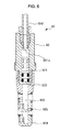
- FIG. 6 is an overall cross-sectional side view of release member.
- FIG. 7 is an overall cross-sectional side view of disabling reverse transmission member (restricted state).
- FIG. 8 is a side view of the holding force adjusting apparatus of the present invention in standby state with an object (light weight) placed thereon.
- FIG. 9 is a side view of the holding force adjusting apparatus of the present invention when inclined (acting state) with an object (light weight) placed thereon.
- FIG. 10 is a side view of the holding force adjusting apparatus of the present invention in standby state with an object (heavy weight) placed thereon.
- FIG. 11 is a side view of the holding force adjusting apparatus of the present invention when inclined (acting state) with an object (heavy weight) placed thereon.
- FIG. 12 is a side view showing an example of actual operating condition of the holding force adjusting apparatus of the present invention.
- FIG. 1 is a side view and FIG. 2 is a perspective view of a posture holding apparatus 1 that holds a placed object employed in the holding force adjusting apparatus of the present invention.
- the posture holding apparatus 1 that holds a placed object is provided with
- the base 2 is structured by a mounting platform 21 on which an object will be placed, and a substrate 22 disposed on the lower side of the mounting platform 21 .
- the substrate 22 and the base 2 are connected by a hinge 221 disposed near one end of the base 2 such that they can swing freely.
- the substrate 22 is provided with a pair of side members 222 a and 222 b that are placed in parallel with each other, a substrate 223 constructed between the side members 222 a and 222 b , and beam 224 .
- the side members 222 a and 222 b are of the same shape, in which the pin shaft of the hinge 221 is inserted in the end, and the substrate 223 and beam 224 are disposed in sequence towards the base end section.
- the lower side of the substrate 223 is connected to the tip of a strut 71 and the base end of the strut 71 is connected to the pedestal 72 .
- the pedestal 72 can have any configuration, and for example, as shown in FIG. 12 , it may be configured of a plurality of legs 73 disposed radially from the base end of the strut 71 , and casters 74 provided at the tip of the legs 73 .
- the strut 71 is rotatably connected to the substrate 223 . Further, strut 71 may be configured such that adjustment mechanism enabling adjustment to any length is included, and the height of mounting platform 21 can be varied.
- the substrate 223 when an object is placed on the mounting platform 21 , is located on the vertical line passing through the center of gravity of the placed object, or is located in a position that is closer to the hinge 221 than the said vertical line.
- the base end of side members 222 a and 222 b is provided with long holes 225 a and 225 b respectively as distance adjusting members.
- an oscillating shaft 31 of the supporting member 3 is inserted between the side members 222 a and 222 b in a freely-rotatable manner, and the supporting member 3 is supported to the base 2 by this oscillating shaft 31 such that it can swing freely.
- Both ends of the oscillating shaft 31 are connected to one end of the swing members 32 a and 32 b that are bent in an L-shape, and a supporting member 3 is connected to the other end of each of the swing members 32 a and 32 b .
- the supporting member 3 is located along a side of the object placed on the mounting platform 21 , and when the object placed on the mounting platform 21 leans towards the supporting member 3 , a push back action so as restore the placed object to the original state (posture) will manifest.
- a supporting member 3 swings between the standby state before the inclination (the state in FIG. 1 and FIG. 8 ) and the working state in which the placed object is inclined towards the supporting member 3 (the state in FIG. 9 , and FIG. 11 ).
- a connecting member 33 that bridges between the oscillating members 32 a and 32 b is provided near the other end of the swing members 32 a and 32 b , and the both ends of the connecting member 33 are connected with connecting members 41 a and 41 b respectively.
- a movement member 95 is connected at the base ends of the connecting members 41 a and 41 b as adjustment member such that it can swing freely.
- long holes 42 a and 42 b are formed respectively (the long hole of the connecting member 41 b is not shown), and a connecting member 33 is inserted inside each of the long holes 42 a and 42 b.
- the long holes 225 a and 225 b formed in the side members 222 a and 222 b are formed inclined with respect to the seat surface of the mounting platform 21 , and are provided so as to position below the oscillating shaft 31 and also in the lower side of the connecting member 33 at all times. Further, the long holes 225 a and 225 b are formed in a direction such that the distance between the moving member 95 and connecting member 33 will change by the movement of the moving member 95 in the long holes 225 a and 225 b .
- the moving member 95 and the connecting member 33 when the supporting member 3 is in a standby state and when the moving member 95 is positioned in the upper end, the moving member 95 and the connecting member 33 are in the farthest position from each other, and when positioned at the lower end, they will be in a state of closest approach.
- the actual length of the connecting members 41 a and 41 b can be changed based on the change in the distance between the moving member 95 and the connecting member 33 .
- the connecting member 41 a is comprised of a wide base end part 411 a and a tip 412 a that is configured to be narrower than the base end part 411 a .
- a spring 50 a as an elastic member is mounted in compressed state on the exterior of the tip 412 a .
- One end face of the spring 50 a abuts a spring receiving part 414 a interposed between the connecting member 33 , while the other end face of the spring 50 a abuts the stepped portion 413 a between base end section 411 a and tip 412 a .
- springs 50 a and 50 b are biased towards the direction in which the connecting member 33 is pushed up at all times, and as a result, the biasing force (restoring force) is being applied in the direction of returning the supporting member 3 to the standby state.
- the above-mentioned connecting members 41 a and 41 b , and springs 50 a and 50 b constitute the swinging support member 4 .
- FIG. 3 is a side cross-sectional view of the pressure actuator 8 a . Since both of the pressure actuators 8 a and 8 b have the same configuration, the pressure actuator 8 a will be explained, whereas the explanation of the pressure actuator 8 b will be omitted.
- the pressure actuator 8 a is a mechanism to output the input movement amount as liquid pressure, and the pressure actuator 8 a acquires the weight of the placed object loaded on the mounting platform 21 as a movement amount of the piston rod and outputs it as the liquid pressure (oil pressure).
- the configuration of the pressure actuator 8 a is described below.
- the pressure actuator 8 a is comprised of a cylinder 81 fixed on the base substrate 223 , a piston 82 housed inside the cylinder 81 such that it can reciprocate freely, and a lid 83 for closing the opening of the cylinder 81 .
- oil is loaded as the pressure transmitting medium.
- the piston head 821 moves in the cylinder 81
- the volume of the storage room 811 changes, and along with this change, the oil in the storage room 811 flows out or in through opening 812 of the cylinder 81 .
- a piston rod 822 is connected to the piston head 821 , and the piston rod 822 protrudes from the center of the lid 83 to outside.
- the tip of the piston rod 822 is of spherical shape, and abuts the lower surface of the mounting platform 21 .
- a spherical recessed part 211 is formed in the abutting section of the piston rod 822 , and is configured such that the contact angle of the piston rod 822 with respect to mounting table 21 can be freely changed.
- the number of pressure actuators 8 a and 8 b described above is not limited to two, and can be one, or three or more. In case of providing a plurality of pressure actuators, it is preferable to dispose them evenly with respect to the plane of the mounting platform 21 .
- the opening 812 is connected with one end of the flow path 89 a .
- the other end of the flow path 89 a is connected to a disabling reverse transmission member 6 (described later), and the pressure output from the pressure actuator 8 a is eventually fed to the cylinder chamber (pressure receiving chamber) 911 of the movement amount actuator 9 .
- oil pressure from the pressure actuator 8 b is also fed to the cylinder chamber 91 of the movement amount actuator 9 .
- the liquid pressure output from all pressure actuators 8 is aggregated in the cylinder chamber 91 of the movement amount actuator 9 .
- the flow path 89 a is configured of a flexible resinous tube
- the flow paths 89 b to 89 d are also configured of a flexible resinous tube.
- FIG. 4 is a side cross-sectional view of the actuator 9 .
- the movement amount actuator 9 is comprised of a cylinder 91 , a piston 92 housed inside the cylinder 91 , and a lid 93 to cover an opening of the cylinder 91 .
- the lid 93 is fixed on the beam 224 , and the piston rod 922 of piston 92 penetrates through the lid 93 and beam 224 and protrudes on the lower side of the beam 224 .
- the piston head 921 moves inside the cylinder 91 , and a receiving chamber 911 is defined by the inner wall of the cylinder 91 and the piston head 921 .
- a receiving chamber 911 is defined by the inner wall of the cylinder 91 and the piston head 921 .
- the pressure-receiving chamber 911 receives the oil pressure that is output from the pressure actuators 8 a and 8 b , and the pressure received by the receiving chamber 911 is converted to a movement amount of piston rod 922 .
- a compression spring 925 is interposed between the piston head 921 and lid 93 , and they bias the piston head 921 in the direction in which the volume of the pressure receiving chamber becomes none. Accordingly, when an object is not placed on the mounting platform 21 , it is maintained in a state in which the volume of the pressure receiving chamber is zero, and the oil is pushed back towards the pressure actuators 8 a and 8 b.
- connection guide member 94 is provided at the tip of the piston rod 922 , and this connection guide member 94 is provided with a long hole 941 as a guide section.
- a moving member 95 is inserted through the long hole 941 .
- the connection guide member 94 moves (downward), and the moving member 95 inside the connection guide member 94 will also move (downward) simultaneously.
- the moving member 95 moves in the moving direction of the connection guide member 94 , and it is guided by the long holes 225 a and 225 b to move in a direction that intersects the moving direction of the connection guide member 94 (the direction intersecting at right angles (horizontal direction)).
- the long hole 941 of the connection guide member 94 is intended for allowing a movement of the moving member 95 in the horizontal direction along with vertical movement (along with the back and forth movement of the piston rod 922 , movement in a direction intersecting with this).
- the long holes 225 a and 225 b function as displacement amount adjusting parts for adjusting the length (displacement amount) of the springs 50 a and 50 b in standby state by adjusting the distance between the connecting member 33 of the moving member 95 .
- a disabling reverse transmission member is provided to regulate the distribution of oil, which is the pressure transmitting medium.
- This disabling reverse transmission member allows the flow of liquid from pressure actuators 8 a and 8 b to the movement amount actuator 9 , and regulates the flow from the movement amount actuator 9 to pressure actuators 8 a and 8 b as a rule.
- the disabling reverse transmission member 6 is described below with reference to FIG. 5 .
- the disabling reverse transmission member 6 is a check valve that allows the flow of oil, which is the pressure transmission medium, in only one direction, and stops the flow in the reverse direction, and this check valve is provided with a release device for releasing the backflow restriction.
- the check valve body 61 includes a valve chamber 611 that houses the valve body 63 in the inside, and an output side cylinder chamber 612 .
- the output side cylinder chamber 612 and valve chamber 611 are connected through an interconnecting passage 613 , and two flow paths 613 a and 613 b are connected to the interconnecting passage 613 .
- the other end of the flow path 89 a is connected to the flow passage 613 a
- the other end of the flow path 89 b is connected to the flow passage 613 b .
- the output side cylinder chamber 612 is connected to the flow passage 612 a
- the flow passage 612 a is connected to one end of the flow path 89 d .
- the valve chamber 611 is connected to the flow passage 611 a , and the flow passage 611 a is connected to the other end of the flow path 89 c.
- a valve body 63 and a disk-shaped guide member 65 are housed inside the valve chamber 611 .
- the guide pins 631 and 632 are extended in the longitudinal direction along the axial direction (moving direction of the valve body, i.e. the flow direction of oil), whereas the rear end pin 631 is slidably inserted in the guide hole 651 formed in the center of the guide member 65 .
- a plurality of flow-through holes 652 are formed around the guide hole 651 .
- the front end pin 632 of the valve body 63 is slidably inserted into the insertion hole 642 formed in the tip of the piston rod 641 of the output side piston 64 (described later).
- the valve body 63 is guided so as to reciprocate on the shaft line by the guide hole 651 and insertion hole 642 .
- a convex taper is formed on the outer peripheral portion of the valve body 63 , and a sealing member is further provided in the exterior, which overlaps with the valve port 611 h formed in the connecting part of valve chamber 63 and flow passage 613 to have the function of closing the valve port 611 h .
- the valve port 611 h has a configuration such that, since a recess taper having an inclination angle the same as the convex taper of the valve body 63 is formed, the valve body 63 opens for the flow towards the moving amount actuator 9 from pressure actuators 8 a and 8 b , and regarding the flow in the reverse direction, the valve body 63 closes by being pressed against the valve body 63 or the valve port 611 h.
- an output side piston 64 is housed in the output side cylinder chamber 612 , and if the pressure inside the output side cylinder chamber 612 increases due to supply of the fluid from the flow passage 612 a , the piston 64 moves in the direction of the valve body 63 .
- the output side cylinder chamber 612 is connected to an input side cylinder chamber 621 of the release member 60 through the flow path 89 d.
- the configuration of the release member 60 is described below with reference to FIG. 6 .
- the input side cylinder chamber 621 is provided inside the cylinder body 62 , and an input side piston 622 is accommodated in the input side cylinder chamber 621 .
- the input side cylinder chamber 621 is connected to the other end of the flow path 89 d via the flow passage 621 a .
- the piston rod 623 of the input side piston 622 protrudes from the input side cylinder chamber 621 and functions as a detection member, and a contact member 624 is provided at the tip of the piston rod 623 .
- a compressed spring 625 is inserted between the contact member 624 and the tip of the cylinder body 62 .
- the piston rod 623 is biased in the direction of protrusion by spring 625 .
- the cylinder body 62 is fixed to the lower rear end of the mounting platform 21 , and is disposed so as to project the piston rod 623 in the rear direction.
- the contact member 624 is in contact with the swing member 32 b.
- the contact member 624 abuts the swing member 32 b when in a standby state where the swing members 32 a and 32 b are not inclined, and in this state, the piston rod 623 is in a state of having been pushed into the cylinder body 62 to a maximum extent.
- the inside volume of the cylinder 621 is the least.
- valve body 63 Since this releases the contact of the piston rod 641 with the valve body 63 , the valve body 63 will be able to move in a direction to close the valve port 611 h , and the flow of the oil from the movement amount actuator 9 towards pressure actuators 8 a and 8 b will stop.
- the amount of movement of the output side piston 64 can be made larger than the amount of movement of the input side piston 622 , and upon detecting the restoration of the swing member 32 b to the standby position by the movement of the piston rod 623 of the input side piston 622 , the valve body 63 is moved reliably, and the reverse-disabled state is released.
- a wire or ring mechanism may also be employed.
- the bias force adjust member 5 is comprised of movement amount actuator 9 , connecting guide member 94 , moving member 95 , long holes 225 a and 225 b as a distance adjusting member, and connecting members 41 a and 41 b described above.
- the holding force adjusting apparatus is comprised of a liquid pressure output member, elastic member, bias force adjust member 5 , and a disabling reverse transmission member.
- FIG. 1 when in a state wherein an object is not placed on the mounting platform 21 (initial state), oil has been returned to the pressure actuators 8 a and 8 b , the piston rod 822 is in the most protruded state, and the piston rod 922 of the movement amount actuator 9 is in the most retracted state. Accordingly, moving member 95 and connecting member 33 are in the farthest position from each other, and the supporting member 3 is in a standby state of the initial state.
- the biasing force in the return direction that is imparted to the supporting member 3 is also none or in the minimum state (state L 0 wherein the spring 50 a is most extended). Further, the contact member 624 of the release member 60 is in a state of the most pressed by the swing member 32 b , and the valve body 63 of the disabling reverse transmission member 6 is away from the valve port 611 h (released state).
- the holding force exerted by the supporting member 3 is imparted by the biasing force of the spring 50 a
- such a biasing force is determined by the total displacement amount ( ⁇ 0+ ⁇ n) obtained by adding the deformed displacement amount ⁇ n when the supporting member 3 is inclined to the displacement amount ⁇ 0 of standby state.
- the total displacement amount is varied (increased) by varying (increasing) the amount of displacement ⁇ 0 in the standby state, i.e. by making the displacement amount ⁇ 0 vary (increase) in standby state, and the holding force of the supporting member 3 is eventually varied (increased) according to the weight.
- the posture holding apparatus for holding a placed object according to the present invention is provided with a configuration in which, the restoring force from a supporting member changes in accordance with the weight of the placed object, and the biasing force (restoring force) from the supporting member increases as the weight of the placed object increases. That is, the posture holding apparatus for holding a placed object according to the present invention can fully realize posture-retaining force to push back the inclined placed object to original state while maintaining appropriate shock absorbing action for the inclined object, and the posture holding apparatus of the present invention accommodates objects having a wide range of loads from lightweight to heavy weight.
- the springs 50 a and 50 b are not limited to compressible springs, and it is also possible to use a tension spring, or a torsion spring wound around the oscillating shaft 31 .
- the object placed on the mounting platform 21 can be anything, but the present invention is particularly useful for a case in which the center of gravity of the placed object shifts in the placed state, and proper support from a supporting member becomes necessary.
- the examples of these can be humans, animals, or a container containing liquid or the like.
- the hip region and the back are respectively supported as the hip region leans from the top of the mounting platform 21 and the back Hmb of the body reclines onto the support member 3 from the front side.
- the pressure actuator 8 and movement amount actuator 9 feed various displacement amount to the bias force adjust member 5 through the above mechanism. Consequently, the initial compression amount of the spring 50 , i.e. the biasing force to push back the supporting member 3 to the initial position, changes by the action of the bias force adjust member 5 .
- the human sitting on the posture holding apparatus receives the reaction force applied to the back Hmb of the body via the supporting member 3 as a value that is appropriate for each body weight.
- a supporting member 3 is inclined from the initial position to the rear side by changing the posture (shown in FIG. 12 by imaginary line)
- the posture shown in FIG. 12 by imaginary line
- the supporting member 3 is pushed back so that the back (of the body) is pushed back, and the posture will not be imbalanced.
- the biasing force to push back the supporting member 3 to the initial position is adjusted as appropriate when the hip part of human rests on the mounting platform 21 , it is not necessary to separately provide a manual adjusting means having a complicated mechanism.
Abstract
Description
-
- a base onto which a substance to be placed,
- a supporting member which is attached onto the base so that the supporting member freely swings between a standby state where the supporting member does not support the substance and an active state where the supporting member supports the substance in an inclination state, the supporting member being positioned on a side of the base, and
- a swinging support having a biasing force for returning the supporting member to the standby state when the supporting member is inclined, the holding force adjusting apparatus being designed to adjust a biasing force of the swinging support member, the holding force adjusting apparatus including,
- a weighting detection member for detecting weight of the substance to be placed; and
- a returning force adjusting member for adjusting the bias force according to a detected weight by the weight detecting means.
- a
base 2, a supportingmember 3 disposed on a side of thebase 2, - a swinging support member 4 that freely swings to support the supporting
member 3 with respect to thebase 2, - springs 50 a and 50 b as elastic members for biasing the supporting
member 3 towards an object placed on thebase 2, - a bias force adjust member 5 for adjusting the biasing force obtained from the
springs - a pressure actuator 8 as a liquid pressure output member to change the liquid pressure caused by the load of the object placed on the
base 2, and - a movement amount actuator 9 that converts the output liquid pressure to reciprocating quantity.
Claims (8)
Applications Claiming Priority (4)
| Application Number | Priority Date | Filing Date | Title |
|---|---|---|---|
| JP2012-158168 | 2012-07-13 | ||
| JP2012158168 | 2012-07-13 | ||
| JP2012247949 | 2012-11-09 | ||
| JP2012-247949 | 2012-11-09 |
Publications (2)
| Publication Number | Publication Date |
|---|---|
| US20140014805A1 US20140014805A1 (en) | 2014-01-16 |
| US9239129B2 true US9239129B2 (en) | 2016-01-19 |
Family
ID=48783021
Family Applications (2)
| Application Number | Title | Priority Date | Filing Date |
|---|---|---|---|
| US13/941,158 Active - Reinstated 2033-10-09 US9239129B2 (en) | 2012-07-13 | 2013-07-12 | Holding force adjusting apparatus |
| US13/941,217 Expired - Fee Related US9605796B2 (en) | 2012-07-13 | 2013-07-12 | Posture holding apparatus |
Family Applications After (1)
| Application Number | Title | Priority Date | Filing Date |
|---|---|---|---|
| US13/941,217 Expired - Fee Related US9605796B2 (en) | 2012-07-13 | 2013-07-12 | Posture holding apparatus |
Country Status (3)
| Country | Link |
|---|---|
| US (2) | US9239129B2 (en) |
| EP (2) | EP2684491A1 (en) |
| JP (3) | JP6000200B2 (en) |
Cited By (4)
| Publication number | Priority date | Publication date | Assignee | Title |
|---|---|---|---|---|
| US10285502B2 (en) * | 2017-09-20 | 2019-05-14 | La-Z-Boy Incorporated | Furniture member with adjustable seat height |
| US10492613B2 (en) | 2017-09-20 | 2019-12-03 | La-Z-Boy Incorporated | Legrest mechanism for furniture member |
| US10537177B2 (en) | 2017-09-20 | 2020-01-21 | La-Z-Boy Incorporated | Furniture member with adjustable seat depth |
| US10561244B2 (en) | 2017-09-20 | 2020-02-18 | La-Z-Boy Incorporated | Furniture member with recline and tilt |
Families Citing this family (6)
| Publication number | Priority date | Publication date | Assignee | Title |
|---|---|---|---|---|
| CN106455821A (en) | 2014-04-17 | 2017-02-22 | Hni技术公司 | Chair and chair control assemblies, systems, and methods |
| CN105193123A (en) * | 2015-09-29 | 2015-12-30 | 平湖市当湖街道超越时空模具图文设计服务部 | Novel buffer chair |
| ITUB20154688A1 (en) * | 2015-10-15 | 2017-04-15 | Co Fe Mo Ind S R L | OSCILLATION MECHANISM FOR ADJUSTABLE CHAIRS |
| IT201600071468A1 (en) | 2016-07-08 | 2018-01-08 | Co Fe Mo Ind S R L | OSCILLATION MECHANISM FOR CHAIRS |
| US11197548B2 (en) * | 2019-12-16 | 2021-12-14 | Allseating Corporation | Reclining control system for a chair |
| CN113560259B (en) * | 2021-07-30 | 2022-07-05 | 西安广核阀门科技有限公司 | Device and method for cleaning interior of valve |
Citations (12)
| Publication number | Priority date | Publication date | Assignee | Title |
|---|---|---|---|---|
| US4830432A (en) * | 1986-05-15 | 1989-05-16 | Stabilus Gmbh | Positioning device |
| JPH0271347U (en) | 1988-11-19 | 1990-05-30 | ||
| DE4007179A1 (en) | 1990-03-07 | 1991-09-12 | Stabilus Gmbh | Load-dependent chair backrest adjustment - has displacement cylinder connected to backrest and engaging lockable gas spring |
| JPH03122740U (en) | 1990-03-28 | 1991-12-13 | ||
| US5577803A (en) * | 1992-11-04 | 1996-11-26 | Tritube | Adjustable seat |
| US5769492A (en) * | 1996-12-10 | 1998-06-23 | Jensen; Robert J. | Back saver sport seat |
| JP2006181101A (en) | 2004-12-27 | 2006-07-13 | Kokuyo Furniture Co Ltd | Chair equipped with device for adjusting reaction force against tilt |
| US7198329B1 (en) * | 2003-10-23 | 2007-04-03 | Larson John E | Height adjustable work chair |
| US20070170762A1 (en) | 2003-12-02 | 2007-07-26 | Christian Erker | Seatback adjustment |
| JP3136349U (en) | 2007-07-26 | 2007-10-25 | 直高 鉛 | Load collapse prevention device |
| JP2009082529A (en) | 2007-10-01 | 2009-04-23 | Kokuyo Co Ltd | Chair |
| US8029060B2 (en) * | 2006-10-04 | 2011-10-04 | Formway Furniture Limited | Chair |
Family Cites Families (9)
| Publication number | Priority date | Publication date | Assignee | Title |
|---|---|---|---|---|
| US4717164A (en) * | 1986-05-27 | 1988-01-05 | Shmuel Levavi | Road vehicle including banking, steering, braking and other controls |
| JPH03222907A (en) * | 1989-11-30 | 1991-10-01 | Itoki Kosakusho Co Ltd | Elastic force regulator of desk |
| JPH062671Y2 (en) * | 1992-01-31 | 1994-01-26 | パラマウントベッド株式会社 | Back-raising mechanism with emergency release means |
| US20070135982A1 (en) * | 1995-06-07 | 2007-06-14 | Automotive Technologies International, Inc. | Methods for Sensing Weight of an Occupying Item in a Vehicular Seat |
| US7900736B2 (en) * | 1995-06-07 | 2011-03-08 | Automotive Technologies International, Inc. | Vehicular seats with fluid-containing weight sensing system |
| JP3136349B2 (en) | 1995-07-07 | 2001-02-19 | 株式会社エス・アイ・システム | Irregular play determination device |
| JP2000350641A (en) * | 1999-06-14 | 2000-12-19 | Masami Hidaka | Aid for stabilizing sitting position and attitude on chair |
| WO2004107917A1 (en) * | 2003-05-23 | 2004-12-16 | Manplus Co., Ltd. | Chair having automatically adjustable backrest |
| JP5490004B2 (en) * | 2007-09-20 | 2014-05-14 | ハーマン、ミラー、インコーポレイテッド | Body support structure |
-
2013
- 2013-07-11 EP EP13176142.1A patent/EP2684491A1/en not_active Withdrawn
- 2013-07-12 US US13/941,158 patent/US9239129B2/en active Active - Reinstated
- 2013-07-12 US US13/941,217 patent/US9605796B2/en not_active Expired - Fee Related
- 2013-07-13 JP JP2013147136A patent/JP6000200B2/en not_active Expired - Fee Related
- 2013-07-13 JP JP2013147134A patent/JP5631455B2/en active Active
- 2013-07-13 JP JP2013147135A patent/JP5809204B2/en not_active Expired - Fee Related
- 2013-07-15 EP EP13176428.4A patent/EP2684492B1/en not_active Not-in-force
Patent Citations (12)
| Publication number | Priority date | Publication date | Assignee | Title |
|---|---|---|---|---|
| US4830432A (en) * | 1986-05-15 | 1989-05-16 | Stabilus Gmbh | Positioning device |
| JPH0271347U (en) | 1988-11-19 | 1990-05-30 | ||
| DE4007179A1 (en) | 1990-03-07 | 1991-09-12 | Stabilus Gmbh | Load-dependent chair backrest adjustment - has displacement cylinder connected to backrest and engaging lockable gas spring |
| JPH03122740U (en) | 1990-03-28 | 1991-12-13 | ||
| US5577803A (en) * | 1992-11-04 | 1996-11-26 | Tritube | Adjustable seat |
| US5769492A (en) * | 1996-12-10 | 1998-06-23 | Jensen; Robert J. | Back saver sport seat |
| US7198329B1 (en) * | 2003-10-23 | 2007-04-03 | Larson John E | Height adjustable work chair |
| US20070170762A1 (en) | 2003-12-02 | 2007-07-26 | Christian Erker | Seatback adjustment |
| JP2006181101A (en) | 2004-12-27 | 2006-07-13 | Kokuyo Furniture Co Ltd | Chair equipped with device for adjusting reaction force against tilt |
| US8029060B2 (en) * | 2006-10-04 | 2011-10-04 | Formway Furniture Limited | Chair |
| JP3136349U (en) | 2007-07-26 | 2007-10-25 | 直高 鉛 | Load collapse prevention device |
| JP2009082529A (en) | 2007-10-01 | 2009-04-23 | Kokuyo Co Ltd | Chair |
Cited By (4)
| Publication number | Priority date | Publication date | Assignee | Title |
|---|---|---|---|---|
| US10285502B2 (en) * | 2017-09-20 | 2019-05-14 | La-Z-Boy Incorporated | Furniture member with adjustable seat height |
| US10492613B2 (en) | 2017-09-20 | 2019-12-03 | La-Z-Boy Incorporated | Legrest mechanism for furniture member |
| US10537177B2 (en) | 2017-09-20 | 2020-01-21 | La-Z-Boy Incorporated | Furniture member with adjustable seat depth |
| US10561244B2 (en) | 2017-09-20 | 2020-02-18 | La-Z-Boy Incorporated | Furniture member with recline and tilt |
Also Published As
| Publication number | Publication date |
|---|---|
| US20140014806A1 (en) | 2014-01-16 |
| JP2014110880A (en) | 2014-06-19 |
| JP5809204B2 (en) | 2015-11-10 |
| JP2014110881A (en) | 2014-06-19 |
| JP5631455B2 (en) | 2014-11-26 |
| EP2684492B1 (en) | 2017-06-21 |
| US9605796B2 (en) | 2017-03-28 |
| US20140014805A1 (en) | 2014-01-16 |
| JP2014110882A (en) | 2014-06-19 |
| EP2684492A1 (en) | 2014-01-15 |
| JP6000200B2 (en) | 2016-09-28 |
| EP2684491A1 (en) | 2014-01-15 |
Similar Documents
| Publication | Publication Date | Title |
|---|---|---|
| US9239129B2 (en) | Holding force adjusting apparatus | |
| CA2047746C (en) | Synchronous adjusting device for office chairs or the like | |
| US10011475B1 (en) | Bucket bottling stand | |
| EP3563808B1 (en) | Hydraulic prosthetic ankle | |
| CN101675846B (en) | Vertically adjustable furniture item | |
| US6706074B1 (en) | Artificial knee joint assembly capable of maintaining a knee angle between a lower leg and a thigh when the assembly stands on a horizontal or inclined surface | |
| WO2009084915A1 (en) | A gas cylinder | |
| US8444705B2 (en) | Knee joint prosthesis | |
| JPS6035573B2 (en) | linear air spring device | |
| KR101955857B1 (en) | Bookshelf assembly | |
| WO2021099737A1 (en) | Aircraft seat | |
| WO2017208520A1 (en) | Overturn prevention device | |
| CN210218290U (en) | Hydraulic cylinder with buffer function | |
| US20090223761A1 (en) | Self leveling shock absorber | |
| FR2880258A1 (en) | KNEE PROTHETIC JOINT STRUCTURE | |
| JP2021142212A (en) | Chair seat plate support mechanism | |
| KR101919147B1 (en) | shock absorbing device of air pressure vessel | |
| JP6205445B2 (en) | Fall prevention device and method of mounting the same | |
| WO2017169295A1 (en) | Damper and fall prevention device with said damper | |
| KR101624577B1 (en) | Shock absorbing bed of ambulance | |
| KR20190075312A (en) | weight supporting table | |
| FR2765787A1 (en) | Bed moved between horizontal and vertical positions | |
| CN108006009B (en) | A kind of cylinder cushion device | |
| EP1260249A1 (en) | Exercise apparatus with pneumatic cylinder | |
| KR102035079B1 (en) | Simple table |
Legal Events
| Date | Code | Title | Description |
|---|---|---|---|
| AS | Assignment |
Owner name: FUMOTO GIKEN CO., LTD., JAPAN Free format text: ASSIGNMENT OF ASSIGNORS INTEREST;ASSIGNORS:YAMAMOTO, RYOUHEI;YAMAMOTO, YUHO;YAMAMOTO, NAOYUKI;REEL/FRAME:030790/0309 Effective date: 20130708 |
|
| ZAAA | Notice of allowance and fees due |
Free format text: ORIGINAL CODE: NOA |
|
| ZAAB | Notice of allowance mailed |
Free format text: ORIGINAL CODE: MN/=. |
|
| ZAAA | Notice of allowance and fees due |
Free format text: ORIGINAL CODE: NOA |
|
| ZAAB | Notice of allowance mailed |
Free format text: ORIGINAL CODE: MN/=. |
|
| STCF | Information on status: patent grant |
Free format text: PATENTED CASE |
|
| AS | Assignment |
Owner name: FUMOTO GIKEN CO., LTD., JAPAN Free format text: CHANGE OF ASSIGNEE'S ADDRESS;ASSIGNOR:FUMOTO GIKEN CO., LTD.;REEL/FRAME:046906/0090 Effective date: 20180803 |
|
| MAFP | Maintenance fee payment |
Free format text: PAYMENT OF MAINTENANCE FEE, 4TH YR, SMALL ENTITY (ORIGINAL EVENT CODE: M2551); ENTITY STATUS OF PATENT OWNER: SMALL ENTITY Year of fee payment: 4 |
|
| FEPP | Fee payment procedure |
Free format text: MAINTENANCE FEE REMINDER MAILED (ORIGINAL EVENT CODE: REM.); ENTITY STATUS OF PATENT OWNER: SMALL ENTITY |
|
| LAPS | Lapse for failure to pay maintenance fees |
Free format text: PATENT EXPIRED FOR FAILURE TO PAY MAINTENANCE FEES (ORIGINAL EVENT CODE: EXP.); ENTITY STATUS OF PATENT OWNER: SMALL ENTITY |
|
| PRDP | Patent reinstated due to the acceptance of a late maintenance fee |
Effective date: 20240228 |
|
| FEPP | Fee payment procedure |
Free format text: PETITION RELATED TO MAINTENANCE FEES FILED (ORIGINAL EVENT CODE: PMFP); ENTITY STATUS OF PATENT OWNER: SMALL ENTITY Free format text: PETITION RELATED TO MAINTENANCE FEES GRANTED (ORIGINAL EVENT CODE: PMFG); ENTITY STATUS OF PATENT OWNER: SMALL ENTITY Free format text: SURCHARGE, PETITION TO ACCEPT PYMT AFTER EXP, UNINTENTIONAL. (ORIGINAL EVENT CODE: M2558); ENTITY STATUS OF PATENT OWNER: SMALL ENTITY |
|
| MAFP | Maintenance fee payment |
Free format text: PAYMENT OF MAINTENANCE FEE, 8TH YR, SMALL ENTITY (ORIGINAL EVENT CODE: M2552); ENTITY STATUS OF PATENT OWNER: SMALL ENTITY Year of fee payment: 8 |
|
| STCF | Information on status: patent grant |
Free format text: PATENTED CASE |
|
| FP | Lapsed due to failure to pay maintenance fee |
Effective date: 20240119 |