TECHNICAL FIELD
The present disclosure relates to a massively parallel processing (MPP) database management system and, in particular embodiments, to a management system able to detach the number of database partitions from the number of fixed processors.
BACKGROUND
The concept of massively parallel processing (MPP) is the coordinated processing of a program by multiple processors, with each processor working on different parts of the program. The processors communicate with one another to complete a task with each of them using its own operating system and memory resources.
An MPP database system is based on shared-nothing architecture, with the tables of its databases partitioned into segments and distributed to different processing nodes. There is no data sharing among the processing nodes. When database queries arrive, the work of each query is divided and assigned to one of the processing nodes according to a data distribution plan and an optimized execution plan. The processing entities in each processing node manage only their portion of the data. However, these processing entities may communicate with one another to exchange necessary information during their work execution. A query may be divided into multiple sub-queries, and the sub-queries may be executed in parallel or in some optimal order in some or all the processing nodes. The results of the sub-queries may be aggregated and further processed, and subsequently more sub-queries may the executed according to the results.
One of the challenges in an MPP database system has always been in setting up the distributed system, which includes configuring the machines, creating the database, partitioning the tables, and distributing the segments. How data is distributed and how much the distribution is aligned with the business logic greatly determines the overall performance of the system.
A traditional MPP database system allows a database administrator to create a database and distribute its data (i.e., create database partitions) to a fixed number of processors that are setup ahead of time. Unfortunately, the number of partitions a database administrator can create is fixed and directly corresponds to the number of processors available in the traditional MPP database system. In other words, the number of partitions and the number of processors is always the same. If additional partitions are desired, the entire process of setting up instances and partitions must be repeated.
SUMMARY
An embodiment method for massively parallel processing includes initiating a management instance on an initial machine, the management instance generating an initial partition corresponding to the initial machine, determining a total number of partitions desired for processing a database, the total number of partitions including the initial partition, determining a number of additional machines available to process the database, grouping the initial machine and the additional machines together in a pod, and launching the management instance on the additional machines in the pod to generate the total number of partitions desired for the database.
An embodiment method for massively parallel processing including initiating a management instance on an initial machine, the management instance generating an initial partition corresponding to the initial machine, determining a total number of partitions desired for processing a database, the total number of partitions including the initial partition, determining a number of additional machines available to process the database, a sum total of the additional machines and the initial machine less than the total number of partitions desired, grouping the initial machine and the additional machines together in a pod, and launching the management instance on the additional machines in the pod to generate the total number of partitions desired for the database.
An embodiment massively parallel processing system including an initial machine in a pod, the initial machine running a management instance corresponding to an initial partition for processing a database, and an additional machine in the pod, the additional machine running two of the management instances for processing the database, each of the management instances corresponding to an additional partition.
BRIEF DESCRIPTION OF THE DRAWINGS
For a more complete understanding of the present disclosure, and the advantages thereof, reference is now made to the following descriptions taken in conjunction with the accompanying drawing, in which:
FIG. 1 illustrates a massively parallel processing (MPP) database system configuration for on-line analytical processing (OLAP);
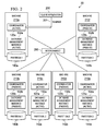
FIG. 2 illustrates an MPP database system configuration for on-line transactional processing (OLTP);
FIG. 3 illustrates a database creation scenario on a traditional MPP database system;
FIG. 4 a illustrates an embodiment MPP database system during an initial setup and formation of a pod;
FIG. 4 b shows the embodiment MPP database system of FIG. 4 a when a database is created and a partitioning policy is defined for the machines in the pod;
FIG. 5 a illustrates an embodiment MPP database system when a number of database partitions is greater than the a number of available machines in the pod;
FIG. 5 b illustrates the embodiment MPP database system of FIG. 5 a when a new machine is added to the pod;
FIG. 6 is a high-level flow diagram illustrating preparation and creation of the database by an information technology (IT) administrator and a database administrator (DBA);
FIG. 7 is a flow diagram illustrating creation of the pod by a pod manager;
FIG. 8 is a flow diagram illustrating a database (DB) management instance handling the creation of a database and its partition;
FIG. 9 is a flow diagram illustrating a pod manager forming a flexible pod and creating the database partitions;
FIG. 10 is a flow diagram illustrating relocation of a database partition when a new machine is added or an existing machine is removed from the pod;
FIG. 11 is a table illustrating example pod configurations; and
FIG. 12 is a table illustrating an example database catalog.
Corresponding numerals and symbols in the different figures generally refer to corresponding parts unless otherwise indicated. The figures are drawn to clearly illustrate the relevant aspects of the embodiments and are not necessarily drawn to scale.
DETAILED DESCRIPTION OF ILLUSTRATIVE EMBODIMENTS
The making and using of the presently preferred embodiments are discussed in detail below. It should be appreciated, however, that the present disclosure provides many applicable inventive concepts that can be embodied in a wide variety of specific contexts. The specific embodiments discussed are merely illustrative and do not limit the scope of the disclosure.
The present disclosure will be described with respect to preferred embodiments in a specific context, namely a massively parallel processing (MPP) database and management thereof. The concepts in the disclosure may also apply, however, to other types of databases and data management systems.
Referring now to FIG. 1, and for the purpose of reference, a conventional or typical massively parallel processing (MPP) database system configuration 10 for on-line analytical processing (OLAP) is illustrated. As shown, a client application 100 presents queries 101 to a machine 110 a having an active coordinator 120 a. The machine 110 a may be operating in conjunction with or alongside another machine 110 b having a passive coordinator 110 b.
Still referring to FIG. 1, the machines 110 a-110 b are operably coupled to the interconnect 160. As the name implies, the interconnect 160 permits the machines 110 a-110 b to communicate with additional machines, namely machines 110 c-110 h. Notably, machines 110 c, 110 e, and 110 g include an active database management instance 130 a, 132 a, and 134 a, respectively. In contrast, machines 110 d, 110 f, and 110 h include a passive database management instance 130 b, 132 b, and 134 b, respectively. Each of the machines 110 c-110 h is associated with one of the database partitions, namely partitions 140 a-144 b as shown in FIG. 1. In the system configuration 10 of FIG. 1, the machine 110 a communicating with the client application 100 and the adjacent machine 110 b do not have an associated partition.
Referring now to FIG. 2, and for the purpose of reference, a conventional or typical MPP database system configuration 20 for on-line transactional processing (OLTP) is illustrated. As shown, a client application 200 presents queries 201 to a machine 210 a having an active coordinator 120 a and an active database (DB) management instance 130 a.
Still referring to FIG. 2, the machine 210 a is operably coupled to the interconnect 260. As the name implies, the interconnect 260 permits the machine 210 b to communicate with additional machines, namely machines 210 b-210 f. Notably, machines 210 c and 210 e include an active coordinator 122 a, 124 a and an active database management instance 132 a, 134 a, respectively. In contrast, machines 210 b, 210 d, and 210 f include a passive coordinator 120 b, 122 b, 124 b and a passive database management instance 130 b, 132 b, 134 b, respectively. Each of the machines 210 a-210 f is associated with one of the database partitions, namely partitions 140 a-144 b as shown in FIG. 1. In the system configuration 20 of FIG. 2, the machine 210 a communicating with the client application 200 has an associated partition 140 a.
Referring now to FIG. 3, a database creation scenario on a traditional massively parallel processing database system 30 is illustrated. As shown in FIG. 3, a client 300 is operably coupled to the interconnect 320. In turn, the interconnect 320 is operably coupled to machines 310 a, 310 b, 310 c. Each of the machines 310 a, 310 b, 310 c includes an active database management instance 330, 332, 334 associated with an empty partition 340, 342, 344, respectively.
Each of the database management instances 330, 332, 334 and the empty partitions 340, 342, 344 in FIG. 3 are created simultaneously. Moreover, as shown in FIG. 3, only one partition is permitted per available machine. If there is a desire to add a new partition or to remove an existing partition in the traditional massively parallel processing database system 30 of FIG. 3, the entire database creation scenario must be performed all over again. As such, the desire to re-partition a database is cumbersome and time consuming for an information technology (IT) administrator and/or a database administrator (DBA).
Referring now to FIG. 4 a, an embodiment MPP database system 40 during an initial setup and formation of a pod 401 (a.k.a., cluster, resource group, etc.). As shown, a client application 400 presents queries to an interconnect 420. The interconnect 420 passes the queries to a machine 410 a. Thereafter, a database management instance 430 a is initiated on an initial machine 410 a.
In an embodiment, the database management instances disclosed herein are running or executing on a processor associated the machine. As shown, the database management instance 430 a generates an initial partition 450 corresponding to the initial machine 410 a. Notably, the initial partition 450 is empty of any data or information.
After the database management instance 430 a and the initial partition 450 have been created, a total number of partitions desired for processing a database is determined. The total number of partitions includes the initial partition 450. Such determination may be based, at least in part, upon the query or instructions received from the client 400.
Once the total number of partitions has been determined, a number of additional machines 410 b, 410 c available to process the database is determined. As used herein, the term machine may refer to and/or incorporate a variety of resources including, for example, a processor, memory, storage node, or other infrastructure. Indeed, the term machine is not meant to be limiting. Also, while two of the additional machines 410 b, 410 c are illustrated in FIG. 4 a, it should be appreciated that more of fewer of the additional machines may be available.
After the number of additional machines (i.e., resources) has been determined, the initial machine 410 a and the additional machines 410 b, 410 c are grouped together in the pod 401. Notably, the machine 410 d associated with the pod administrator 400 is not considered to be an available resource for processing the database and, as such, not included within the pod 401.
Referring collectively to FIGS. 4 a-4 b, after the pod 401 has been defined the management instance 430 a is launched on the additional machines 410 b, 410 c in the pod 401. As shown in FIG. 4 b, this generates the total number of partitions 450, 452, 454 desired for the database. In an embodiment, the machines 410 a, 410 b, 410 c includes a pod manager 440 a, 440 b, 440 c, respectively. The pod managers 440 a, 440 b, 440 c may be used to facilitate communications and cooperation between the machines 410 a, 410 b, 410 c relative to the partitions 450, 452, 454 in the processing of the database.
Referring now to FIG. 5, in an embodiment the client 500 may request, by way of the interconnect 520, for a number of partitions that differs from the number of machines available. In traditional MPP database systems, such a client request would be denied. However, the embodiment management systems disclosed herein are able to accommodate such a request, as more fully explained below.
To handle the request from the client for more or fewer partitions than available resources, the management instance 530 a is initiated on the initial machine 510 a as shown in FIG. 5 a. As shown, the management instance 530 a generates an initial partition 550 corresponding to the initial machine 510 a. Thereafter, the total number of partitions desired for processing the database is determined based on the client 500 request. Notably, the total number of partitions includes the initial partition 550. In the example depicted in FIG. 5 a, the number of partitions (e.g., four) requested by the client exceeds the number of machines available (e.g., three).
Next, a number of additional machines 510 b, 510 c available to process the database is determined. As shown in FIG. 5 a, a sum total of the additional machines 510 b, 510 c and the initial machine 510 a (i.e., three) is less than the total number of partitions 550-556 desired (i.e., four). Thereafter, the initial machine 510 a and the additional machines 510 b, 510 c are grouped together in the pod 501. Then, the management instance 530 b, 530 c, 540 d on the additional machines 510 b, 510 c in the pod 501 is launched to generate the total number of partitions desired for the database. As shown in FIG. 5 a, machine 510 c supports two of the management instances 530 c, 540 d and two of the partitions 554, 556. Notably, the machine 510 d associated with the pod administrator 500 is not considered to be an available resource for processing the database and, as such, not included within the pod 501.
Referring collectively to FIGS. 5 a-5 b, when a new machine 510 e becomes available, the pod 501 is expanded to include that new machine. In that regard, the management instance 530 c and the partition 556 from machine 510 c in FIG. 5 a are relocated to the new machine 510 e as shown in FIG. 5 b. This process of adding new machines (i.e., resources) to the pod 501 may be repeated as the new machines become available. In other words, the pod 501 has a flexible membership and is expandable or contractible over time. As shown in FIG. 5 b, the new machine 510 e may be added to the pod 501 even after the management instances 530 b, 530 c, 530 d were launched on the additional machines 510 b, 510 c in FIG. 5 a.
Referring now to FIG. 6, a high-level flow diagram illustrating an embodiment preparation and creation of the database by an information technology (IT) administrator and a database administrator (DBA) is provided. In block 600, the IT administrator prepares for pod management. Thereafter, in block 620, the DBA creates the pods for the database. In block 630, the DBA creates a database, tables, and the partitions.
Referring now to FIG. 7, a flow diagram illustrating an embodiment creation of the pod 401, 501 by a pod manager is provided. In block 700, the pod manager begins the process of creating the pod. In block 710, an input of pod resources (i.e., parameters) is received. These resources or parameters may include, for example, a compute node, storage, and so on. In block 720, the pod manager validates that the user has authority to create the pod. The pod manager also validates that the user has permission to create the pod directory, and so on. In block 730, the pod manager saves the pod configuration with the pod administrator.
Next, in block 740, the pod manager allocates a storage volume or space. The pod manager also creates and starts one database management instance on one of the nodes (i.e., machines) in the pod. The pod manager further attaches the storage volume to the instance. In block 750, the database management instance (e.g., the database management instance 430 in FIG. 4 a) creates a catalog in the storage. Thereafter, in block 760, the process ends.
Referring now to FIG. 8, a flow diagram illustrating a database (DB) management instance handling the creation of a database and its partition is provided. As shown, in block 800 an embodiment process used to create a massively parallel processing (MPP) database begins. In block 810, a create database command is received by a database management instance (e.g., the database management instance 430 in FIG. 4 a). In block 820, the create database management instruction is handled by the database management instance, which validates input parameters, creates a database structure into its storage (e.g., the empty partition 450 in FIG. 4 a), and saves the database metadata into a catalog in the storage.
In block 830, the database management instance receives commands such as create schema, create table, or create database partition commands. In block 840, a determination of which command is received is made by the database management instance. If the create schema command 842 was received, then in block 850 the database management instance creates schema management information under the associated database structure and saves the schema metadata into a catalog in the storage (e.g., the partition 450). If the create table command 844 was received, then in block 860 the database management instance creates a table structure under the associated database and schema and saves the table metadata into a catalog in the storage (e.g., the partition 450).
If the create database (DB) partition command 846 was received in block 840, then in block 870 the database management instance notes the number of partitions (N) that the user decided upon, selects a data distribution algorithm, creates a database partition structure and metadata, partitions tables accordingly to fit into the database partitions, and saves the database partitioning metadata into a catalog in the storage. In block 870, the database management instance also calls the pod manager (e.g., pod manager 440 a in FIG. 4 a) to create the database management instances on the additional machines or resources (e.g., machines 410 b, 410 c in FIG. 4 b, machines 510 b, 510 c, 510 e in FIGS. 5 a-5 b). Thereafter, in block 880, the process ends.
Referring now to FIG. 9, a flow diagram illustrating an embodiment of a pod manager forming a flexible pod and creating the database partitions is provided. As shown, in block 900 the pod manager (e.g., pod manager 440 a in FIG. 4 a) creates a desired number of partitions (N). In doing so, the pod manager begins by forming a flexible pod (i.e., cluster, resource group) and by creating MPP database partitions. In block 910, the pod manager created a partition-processor map by computing a number of partition(s) per processing node and generating a partition-to-processing node mapping chart. The mapping ensures that the workload is balanced on the available nodes. The mapping may have the configuration of FIG. 4 b (one partition per processing node) or the configuration of FIG. 5 a (one or more partitions per processing node). In an embodiment, an active-to-passive-processing-node mapping chart may be created for each partition.
In block 920, the pod manager creates the database management instances. In doing so, the pod manager keeps the original database management instance (e.g., management instance 430 a in FIG. 4 a) as the instance for the first partition (Partition 1). Then, the pod manager creates, configures, and launches an active database management instance ( instances 430 b, 430 c, and so on) for each of the processing nodes. Then, for each partition (Partition 2 to Partition N) the pod manager allocates a storage space (partition 452, partition 454, etc.). Next, according to the partition-to-processing-node map and the active-to-passive-processing-node map, the storage is attached to the database management instance at the processing node. The instance. Notably, each instance will create a catalog on the storage space (e.g., 430 b-452, 430 c-454, etc.).
In block 930, the pod manager saves the mapping information. In doing so, the pod manager saves the partition-to-processing-node map in the catalog of each storage volume/space. The pod manager also saves the active-to-passive-processing-node map into the catalog. In an embodiment, the information is entered into the catalog through one of the database management instances and the instances synchronize all the catalogs. Thereafter, in block 940, the process ends.
Referring now to FIG. 10, a flow diagram illustrating an embodiment of relocation of a database partition when a new machine is added or an existing machine is removed from the pod is provided. As shown, in block 1000 a pod manager (e.g., pod manager 540 a, 540 b, 540 c in FIGS. 5 a-5 b) is able to add processing node(s) to the pod and remove processing node(s) from the pod. In block 1010, the pod manager receives information about the new node(s) (i.e., machines, resources) to be added or removed. In block 1020, the pod manager alters the partition-processor map. In doing so, the pod manager computes the number of partition(s) per processing node and alters the partition-to-processing-node mapping chart. The new mapping ensures that the workload is balanced on the available nodes. For example, an original mapping may resemble the configuration in FIG. 5 a and a new mapping may resemble the configuration in FIG. 5 b. In an embodiment, the active-to-passive-processing-node mapping chart is altered for each partition.
In block 1030, the pod manager relocates database partitions among processing nodes. If adding nodes, then for each node, the pod manager creates, configures, and launches an active database management instance. The pod manager also moves identified database partitions to their newly designated node by un-mounting a storage space from its current processing node to the new processing node (e.g., 556 from 510 c to 510 e in FIGS. 5 a-5 b). If the storage space is a direct attached storage, the pod manager copies the data to the new designated node. The pod manager also attaches the storage space to the database management instance in the new processing node.
In block 1040, the pod manager saves the mapping information. In doing so, the pod manager saves the updated partition-to-processing-node map on each of the database management instance catalogs. The database manager also saves the active-to-passive-processing-node map into the catalog. In an embodiment, the information is entered into a catalog of one of the database management instances and the instances synchronize their catalog. Thereafter, in block 1050, the process ends.
Referring now to FIG. 11, a table 50 illustrating table illustrating example pod configurations is provided. As shown, the table 50 includes such information as, for example, a pod name, pod users and securing information, the pod network information, the database management instance access information, a list of processing machines/nodes, a list of storage spaces/volumes and their size, cluster, configuration, and system management and monitoring information. In an embodiment, other information may be included in the table 50. Moreover, some of the information may be removed from the table depicted in FIG. 11.
Referring now to FIG. 12, a table 60 illustrating an example database catalog is provided. As shown, the table 60 includes such information as, for example, the database structure and metadata, the schema/database structure and metadata, the table/schema/database structure and metadata, the database partition structure and metadata, the number of partitions (N), the active partition-to-processing-node map, and the active-to-passive-processing-node map. In an embodiment, other information may be included in the table 60. Moreover, some of the information may be removed from the table depicted in FIG. 12.
The current disclosure changes the emphasis of an MPP database to the data itself rather than focusing on the database management instances. In the current disclosure, an MPP database system is first assigned a pool of resources—machines/processors, storage, and possibly also memory that the MPP database system is allowed to access/use. These resources, the processors, storage, and their communication channels do not have to form a pod/cluster (collaborative group) initially. As a database is created and its partitioning policy is defined, the required computing resources are then grabbed from the allocated pool on-demand and managed as a cluster, the necessary number of database management instances is then launched, and the database partitions (each of the data store) are then physically created on the instances. In the present disclosure, the number of database partitions created does not have to directly correspond to or match the actual number of machines (processors). For example, if there are only 5 machines (processors) available, a database administrator can still create 10 database partitions by permitting two partitions to be served by one machine (one processor). When more machines become available, the partitions can be relocated to the available processor at a later time.
While the disclosure provides illustrative embodiments, this description is not intended to be construed in a limiting sense. Various modifications and combinations of the illustrative embodiments, as well as other embodiments, will be apparent to persons skilled in the art upon reference to the description. It is therefore intended that the appended claims encompass any such modifications or embodiments.