US9251930B1 - Segmented shields for use in communication cables - Google Patents
Segmented shields for use in communication cables Download PDFInfo
- Publication number
- US9251930B1 US9251930B1 US13/827,359 US201313827359A US9251930B1 US 9251930 B1 US9251930 B1 US 9251930B1 US 201313827359 A US201313827359 A US 201313827359A US 9251930 B1 US9251930 B1 US 9251930B1
- Authority
- US
- United States
- Prior art keywords
- cable
- shield
- segment
- segments
- electrically conductive
- Prior art date
- Legal status (The legal status is an assumption and is not a legal conclusion. Google has not performed a legal analysis and makes no representation as to the accuracy of the status listed.)
- Active
Links
Images


Classifications
-
- H—ELECTRICITY
- H01—ELECTRIC ELEMENTS
- H01B—CABLES; CONDUCTORS; INSULATORS; SELECTION OF MATERIALS FOR THEIR CONDUCTIVE, INSULATING OR DIELECTRIC PROPERTIES
- H01B11/00—Communication cables or conductors
- H01B11/002—Pair constructions
-
- H—ELECTRICITY
- H01—ELECTRIC ELEMENTS
- H01B—CABLES; CONDUCTORS; INSULATORS; SELECTION OF MATERIALS FOR THEIR CONDUCTIVE, INSULATING OR DIELECTRIC PROPERTIES
- H01B11/00—Communication cables or conductors
- H01B11/02—Cables with twisted pairs or quads
- H01B11/06—Cables with twisted pairs or quads with means for reducing effects of electromagnetic or electrostatic disturbances, e.g. screens
- H01B11/10—Screens specially adapted for reducing interference from external sources
- H01B11/1008—Features relating to screening tape per se
Definitions
- Embodiments of the disclosure relate generally to communication cables and, more particularly, to segmented or discontinuous shields for use in communication cables.
- a continuous shield such as a flexible metallic tube or a foil that coaxially surrounds the cable's conductors.
- shielding based on conventional technology can be expensive to manufacture and/or cumbersome to install in the field.
- complications can arise when a cable is encased by a shield that is electrically continuous between the two ends of the cable.
- the continuous shield can inadvertently carry voltage along the cable, for example from one terminal device at one end of the cable towards another terminal device at the other end of the cable. If a person contacts the shielding, the person may receive a shock if the shielding is not properly grounded.
- continuous cable shields are typically required to be grounded at both ends of the cable to reduce shock hazards and loop currents that can interfere with transmitted signals.
- Such a continuous shield can also set up standing waves of electromagnetic energy based on signals received from nearby energy sources.
- the shield's standing wave can radiate electromagnetic energy, somewhat like an antenna, that may interfere with wireless communication devices or other sensitive equipment operating nearby.
- segmented or discontinuous shields have been incorporated into certain cables.
- These segmented shields typically include metallic patches formed on a polymeric film with gaps or spaces formed between adjacent patches to maintain electrical discontinuity.
- the metallic patches function as an electromagnetic shield; however, it is not necessary to ground the shields during cable installation.
- Current segmented shield designs are typically manufactured by wrapping a shield tape either longitudinally or helically around a cable core. However, the spaces or gaps between the metallic patches may lead to electrical perturbations and decreased performance in the cable. Accordingly, there is an opportunity for improved segmented shields, methods or techniques for forming segmented shields, and/or cables incorporating segmented shields.
- FIG. 1 is a cross-sectional view of an example cable including at least one shield, according to an illustrative embodiment of the disclosure.
- FIG. 2 is a cross-sectional view of another example cable including at least one shield, according to an illustrative embodiment of the disclosure.
- FIG. 3 is a cross-sectional view of another example cable including at least one shield, according to an illustrative embodiment of the disclosure.
- FIG. 4A illustrates a perspective view of an example cable including a segmented shield, according to an illustrative embodiment of the disclosure.
- FIG. 4B illustrates an example technique for wrapping one or more twisted pairs with a shield layer in accordance with certain embodiments of the disclosure.
- FIGS. 5A-5D illustrate example techniques for creating electrically shorted patches within a shield, according to illustrative embodiments of the disclosure.
- FIGS. 6A-6B illustrate cross-sections for example shields that may be utilized to in accordance with various embodiments of the disclosure.
- FIGS. 7A-7D illustrate example electrically conductive patch configurations that may be utilized to form shields in accordance with various embodiments of the disclosure.
- a cable may include one or more transmission media within a core of the cable, such as one or more twisted pairs of conductors.
- one or more transmission media may be individually wrapped or longitudinally enclosed in one or more suitable shields or shield layers.
- one or more groups of transmission media e.g., twisted pairs, etc.
- an external shield may circumscribe a plurality of twisted pairs (and/or other cable components).
- one or more subgroups of twisted pairs may be shielded.
- any combination of shielding arrangements may be utilized.
- at least one shield or shield layer may be formed to include a plurality of longitudinally overlapping segments.
- each segment may include electrically conductive material, and the electrically conductive material of any given may be electrically isolated from that of other segments.
- a shield may be formed from a plurality of longitudinally extending segments. Each segment may be wrapped around one or more transmission media of the cable. For example, each segment may be circumferentially wrapped around one or more twisted pairs (and/or other cable components) to be shielded. According to an aspect of the disclosure, the segments may be arranged adjacent to one another along a longitudinal length of a cable, and an overlap may be formed between each adjacent segment. For example, a first shield segment formed around one or more twisted pairs may have a first longitudinal edge and a second longitudinal edge opposite the first edge. Similarly, a second shield segment formed around the one or more twisted pairs may have a first longitudinal edge and a second longitudinal edge opposite the first edge.
- the first longitudinal edge of the second shield segment may overlap the second longitudinal edge of the first shield segment.
- a third shield segment may overlap the second shield segment, and so on. Any desired overlap may be utilized as desired in various embodiments, such as an overlap of approximately one quarter inch or greater, an overlap of approximately one half inch or greater, an overlap of approximately one inch or greater, or an overlap falling within a desired range.
- individual shield segments may be separately wrapped around one or more twisted pairs (and/or other cable components) during cable assembly such that adjacent shield segments overlap one another.
- a first shield segment may be wrapped around one or more twisted pairs
- a second shield segment may then be wrapped around the one or more twisted pairs so as to overlap an edge of the first shield segment along a longitudinal direction of a cable
- a third shield segment may then be wrapped around the one or more twisted pairs so as to overlap an opposite edge of the second shield segment, and so on.
- a shield may be formed from a plurality of overlapping segments, and the formed shield may be wrapped around one or more twisted pairs or other transmission media. In other words, a preformed shield may be incorporated into a cable during cable assembly.
- the electrical properties of a shield may be improved relative to conventional discontinuous shields.
- conventional discontinuous shields the longitudinal spaces or gaps between adjacent patches of electrically conductive material may lead to electrical perturbations and decreased performance in the cable. These spaces or gaps may be eliminated by certain embodiments of the disclosure, thereby improving electrical performance in the cable.
- a shield having discontinuous electrically conductive shielding elements may be formed, and the shield may provide shielding along the entire length of a cable.
- exposed gaps perpendicular to the cable's longitudinal axis e.g., gaps between electrically conductive patches
- overall alien cross-talk performance may be improved and/or electrical perturbations due to gaps may be reduced or minimized.
- the cable 100 is illustrated as a twisted pair communications cable; however, other types of cables may be utilized, such as other cables that include electrical conductors (e.g., twisted pairs, etc.) and/or composite cables that include a combination of electrical conductors (e.g., twisted pairs, etc.) and other transmission media (e.g., optical fibers, etc.).
- the cable 100 may include any number of transmission media, such as one or more twisted pairs, one or more optical fibers, one or more coaxial cables, and/or one or more power conductors. As shown in FIG.
- the cable 100 may include four twisted pairs 105 A, 105 B, 105 C, 105 D; however, any other number of pairs may be utilized.
- the twisted pairs may be twisted or bundled together and/or suitable bindings may be wrapped around the twisted pairs.
- multiple grouping of twisted pairs may be incorporated into a cable. As desired, each grouping may be twisted, bundled, and/or bound together. Further, in certain embodiments, the multiple groupings may be twisted, bundled, or bound together.
- embodiments of the disclosure may be utilized in association with horizontal cables, vertical cables, flexible cables, equipment cords, cross-connect cords, plenum cables, riser cables, or any other appropriate cables.
- the cable 100 may also include a separator 110 (also referred to as a separation filler, a filler, an interior support, or a spline) configured to orient and or position one or more of the twisted pairs 105 A-D, as well as an outer jacket 115 .
- a separator 110 also referred to as a separation filler, a filler, an interior support, or a spline
- Each twisted pair (referred to generally as twisted pair 105 or collectively as twisted pairs 105 ) may include two electrical conductors, each covered with suitable insulation.
- each of the twisted pairs may have the same twist lay length or alternatively, at least two of the twisted pairs may include a different twist lay length. The different twist lay lengths may function to reduce crosstalk between the twisted pairs.
- each of the twisted pairs may be twisted in the same direction (e.g., clockwise, counter clockwise). In other embodiments, at least two of the twisted pairs may be twisted in opposite directions.
- the insulation may include any suitable dielectric materials (e.g., a polymeric material, polyvinyl chloride (“PVC”), polyurethane, one or more polymers, a fluoropolymer, polyethylene, polypropylene, neoprene, cholorosulphonated polyethylene, fluorinated ethylene propylene (“FEP”), flame retardant PVC, low temperature oil resistant PVC, polyolefin, flame retardant polyurethane, flexible PVC, etc.) and/or combination of materials.
- PVC polyvinyl chloride
- FEP fluorinated ethylene propylene
- the insulation may be foamed. As desired, different foaming levels may be utilized in accordance with twist lay length to result in insulated twisted pairs having an equivalent or approximately equivalent overall diameter.
- the insulation may additionally include other materials, such as a flame retardant material and/or a smoke suppressant material.
- the jacket 115 may enclose the internal components of the cable 100 , seal the cable 100 from the environment, and provide strength and structural support.
- the jacket may be formed from a wide variety of suitable materials, such as a polymeric material, polyvinyl chloride (“PVC”), polyurethane, one or more polymers, a fluoropolymer, polyethylene, polypropylene, neoprene, cholorosulphonated polyethylene, fluorinated ethylene propylene (“FEP”), flame retardant PVC, low temperature oil resistant PVC, polyolefin, flame retardant polyurethane, flexible PVC, low smoke zero halogen (“LSZH”) material, or some other appropriate material known in the art, or a combination of suitable materials.
- PVC polyvinyl chloride
- FEP fluorinated ethylene propylene
- FEP fluorinated ethylene propylene
- LSZH low smoke zero halogen
- the jacket 115 can include flame retardant and/or smoke suppressant materials. Additionally, the jacket 115 may include a wide variety of suitable shapes and/or dimensions. For example, the jacket 115 may be formed to result in a round cable or a cable having an approximately circular cross-section; however, the jacket 115 and internal components may be formed to result in other desired shapes, such as an elliptical, oval, or rectangular shape. The jacket 115 may also have a wide variety of dimensions, such as any suitable or desirable outer diameter and/or any suitable or desirable wall thickness. In various embodiments, the jacket 115 can be characterized as an outer jacket, an outer sheath, a casing, a circumferential cover, or a shell.
- the jacket 115 can be single layer or have multiple layers. In certain embodiments, one or more tubes, tapes, or other layers can be disposed between the jacket 115 and the twisted pairs 105 . In certain embodiments, a shield layer 120 (e.g., a shield tape, etc.) may be disposed between the jacket 115 and the twisted pairs 105 or, alternatively, a shield layer may be incorporated into the jacket 115 or placed on the outside of the jacket. In other embodiments, one or more individual twisted pairs 105 A-D or desired groupings of twisted pairs may be shielded.
- a shield layer 120 e.g., a shield tape, etc.
- any number of cable components may be situated within one or more buffer tubes, such as polypropylene (“PP”) buffer tubes, polyethylene (“PE”) buffer tubes, or polybutylene terephthalate (“PBT”) buffer tubes, and one or more shield layers may be formed on, adhered to, incorporated into, or embedded within the buffer tubes.
- a shield layer (or similarly a tube) may incorporate electrically conductive material in order to provide electrical shielding for one or more cable components.
- the cable 100 may include a separate, armor layer (e.g., a corrugated armor, etc.) for providing mechanical protection.
- Each twisted pair 105 A-D can carry data or some other form of information, for example in a range of about one to ten Giga bits per second (“Gbps”) or another appropriate frequency, whether faster or slower.
- Gbps giga bits per second
- each twisted pair 105 A-D supports data transmission of about two and one-half Gbps (e.g. nominally two and one-half Gbps), with the cable 100 supporting about ten Gbps (e.g. nominally ten Gbps).
- each twisted pair 105 A-D supports data transmission of about ten Gbps (e.g. nominally ten Gbps), with the cable 100 supporting about forty Gbps (e.g. nominally forty Gbps).
- each twisted pair 105 A-D may have a different twist rate.
- the differences between twist rates of twisted pairs 105 that are circumferentially adjacent one another may be greater than the differences between twist rates of twisted pairs 105 that are diagonal from one another (for example the twisted pair 105 A and the twisted pair 105 C).
- the twisted pairs 105 that are diagonally disposed can be more susceptible to crosstalk issues than the twisted pairs 105 that are circumferentially adjacent; however, the distance between the diagonally disposed pairs may limit the crosstalk.
- the different twist lengths and arrangements of the pairs can help reduce crosstalk among the twisted pairs 105 .
- the cable core 125 An opening enclosed by the jacket 115 may be referred to as a cable core 125 , and the twisted pairs 105 may be disposed within the cable core.
- the cable core 125 can be filled with a gas such as air (as illustrated) or alternatively a gelatinous, solid, powder, moisture absorbing material, water-swellable substance, dry filling compound, or foam material, for example in interstitial spaces between the twisted pairs 105 .
- Other elements can be added to the cable core 125 , for example one or more optical fibers, additional electrical conductors, additional twisted pairs, and/or strength members, depending upon application goals.
- At least one shield layer 120 may be provided for the cable 100 , and the shield layer 120 may be wrapped around the collective group of twisted pairs 105 .
- a shield layer 120 that encompasses all of the twisted pairs 105 may be referred to as an external shield 120 .
- the shield 120 may be positioned between the twisted pairs 105 and the outer jacket 115 .
- the shield 120 may be embedded into the outer jacket 115 , incorporated into the outer jacket 115 , or even positioned outside of the outer jacket 115 .
- individual pairs or desired groupings of twisted pairs may be shielded.
- each twisted pair 105 A-D may be individually shielded.
- shield layers may be provided for any desired groupings of twisted pairs.
- multiple shield layers may be provided, for example, individual shields and an overall shield.
- At least one shield such as shield 120
- the shield 120 may be formed to include overlapping segments.
- the shield 120 may be formed to include a plurality of electrically conductive patches arranged in a discontinuous manner.
- the electrically conductive patches may be electrically isolated from one another.
- the shield 120 may not include spaces or gaps between patches along a longitudinal direction of the cable.
- the shield 120 may include a plurality of overlapping segments or sections along a longitudinal length of the cable, and each segment may include at least one electrically conductive patch or portion.
- the combination of the segments may form a discontinuous shield; however, the overlapping nature of the segments may eliminate gaps between certain patches along a longitudinal direction.
- the discontinuous shield 120 may exhibit improved electrical performance relative to conventional discontinuous shields.
- Each shield segment may include a carrier layer (e.g., a dielectric layer, etc.) with one or more electrically conductive patches formed thereon.
- Adjacent shield segments may be positioned in the cable 100 so that an end of a first segment (e.g., a second or distal end along the longitudinal direction or length of the cable 100 ) is overlapped by the first end of a second segment.
- the segments may be incorporated into the cable 100 to include overlapping edges along a length of the cable 100 .
- the carrier layers of the shield segments may provide isolation between the electrically conductive patches formed on each segment.
- a first segment may include an electrically conductive patch formed on a dielectric material.
- a second segment may have a similar construction.
- the dielectric material of the second segment When incorporated into the cable 100 , the dielectric material of the second segment may be in contact with the electrically conductive patch of the first segment at the overlapping region. Thus, electrical isolation exists between the electrically conductive patch of the first segment and the electrically conductive patch of the second segment.
- At least one electrically conductive patch included in a shield may be electrically shorted or continuous along a circumferential direction.
- a shield or a plurality of shield segments
- a patch may contact itself, for example, at the edges of the shield.
- the patch may be electrically shorted to itself, thereby creating a continuous patch in a circumferential direction or along a periphery of the enclosed twisted pairs 105 A-D.
- the shield When the shield is formed to include a plurality of patches that are discontinuous in a longitudinal direction and one or more patches are electrically shorted in a circumferential direction, electrical perturbations caused by the shield may be reduced relative to conventional cables. Therefore, the cable 100 may exhibit improved electrical performance, such as reduced return loss and/or reduced cross-talk loss.
- the shield 120 may be formed from a wide variety of suitable materials as desired in various embodiments.
- the shield 120 may include a plurality of overlapping segments or sections, and each segment may include electrically conductive material.
- electrically conductive material e.g., one or more patches of electrically conductive material
- a carrier or substrate layer e.g., a dielectric layer, a tape, etc.
- the carrier layer may be cut or otherwise divided in order to form segments that will be utilized in the shield 120 .
- respective electrically conductive material may be formed on a plurality of carrier or substrate layers (e.g., precut sections of a dielectric material, etc.) that will be incorporated into the shield 120 .
- carrier or substrate layers e.g., precut sections of a dielectric material, etc.
- one or more patches may be sandwiched between two carrier layers (e.g., two dielectric layers).
- any number of suitable techniques may be utilized as desired to hold the shield segments in place.
- an adhesive e.g., a contact adhesive, a pressure sensitive adhesive, a hot melt adhesive
- shield segments may be adhered or otherwise combined together prior to incorporation of the shield 120 into the cable 100 .
- a first shield segment may overlap a second shield segment along a longitudinal direction of the cable 100 by approximately 0.25 inches (0.00635 meters), 0.5 inches (0.0127 meters), 1 inch (0.0254 meters), 1.5 inches (0.0381 meters), 2 inches (0.0508 meters), more than approximately 0.25 inches, more than approximately 0.5 inches, more than approximately 1 inch, more than approximately 2 inches, a distance included in any suitable range formed using any of the values above, or any other desirable distance.
- a first shield segment may overlap a second shield segment by approximately 8 inches or less.
- a first shield segment may overlap a second shield segment by approximately 1.5 inches or less.
- the overlap distances formed between various pairs of shield segments may be approximately equal. In other embodiments, various pairs of shield segments may have different overlap distances.
- a segment or section of the shield 120 may include a single patch or section of electrically conductive material.
- a segment or section of the shield 120 may include a plurality of electrically conductive patches, and gaps or spaces may be present between adjacent patches.
- a plurality of discontinuous patches may be formed on one side of a carrier layer with gaps between adjacent patches.
- patches may be formed on the other side of the carrier layer to cover the gaps or spaces.
- patch patterns may be formed as desired in various embodiments, and a patch pattern may include a period or definite step.
- patches may be randomly formed or situated on a carrier layer.
- any number of carrier layers and electrically conductive layers may be utilized within a segment of the shield 120 .
- a few example configurations for forming shields are described in greater detail below with reference to FIGS. 6A-B and FIGS. 7A-D .
- a wide variety of suitable techniques and/or processes may be utilized to form a shield 120 (or a shield segment).
- a base material or dielectric material may be extruded, poltruded, or otherwise formed. Electrically conductive material may then be applied to the base material. In other embodiments, electrically conductive material may be injected into the base material. In other embodiments, dielectric material may be formed or extruded over electrically conductive material in order to form a shield 120 .
- suitable techniques may be utilized to incorporate electrically conductive material into a shield 120 .
- the base layer may have a substantially uniform composition and/or may be made of a wide range of materials. Additionally, the base layer may be fabricated in any number of manufacturing passes, such as a single manufacturing pass. Further, the base layer may be foamed, may be a composite, and/or may include one or more strength members, fibers, threads, or yarns. As desired, flame retardant material, smoke suppressants, and/or other desired substances may be blended or incorporated into the base layer.
- the shield 120 may be formed as a tape that includes both a dielectric layer (e.g., plastic, polyester, polyethylene, polypropylene, fluorinated ethylene propylene, polytetrafluoroethylene, polyimide, or some other polymer or dielectric material that does not ordinarily conduct electricity etc.) and an electrically conductive layer (e.g., copper, aluminum, silver, an alloy, etc.) formed on one or both sides of the dielectric layer.
- a separate dielectric layer and electrically conductive layer may be bonded, adhered, or otherwise joined (e.g., glued, etc.) together to form the shield 120 .
- electrically conductive material may be formed on a dielectric layer via any number of suitable techniques, such as the application of metallic ink or paint, liquid metal deposition, vapor deposition, welding, heat fusion, adherence of patches to the dielectric, or etching of patches from a metallic sheet.
- the conductive patches can be over-coated with an electrically insulating film, such as a polyester coating.
- an electrically conductive layer may be sandwiched between two dielectric layers.
- at least two electrically conductive layers may be combined with any number of suitable dielectric layers to form the shield 120 .
- a four layer construction may include respective electrically conductive layers formed on either side of a first dielectric layer.
- a second dielectric layer may then be formed on one of the electrically conductive layers to provide insulation between the electrically conductive layer and the twisted pairs 105 .
- any number of suitable layers of material may be utilized to form a tape which may be used as the shield 120 .
- one or more of the electrically conductive patches included in the shield 120 may be shorted in a circumferential direction.
- the patch may contact itself at the edges of shield 120 (or at or near at least one edge of the shield 120 ) once the shield 120 is wrapped around one or more twisted pairs 105 .
- a wide variety of suitable methods or techniques may be utilized to electrically short patches in a circumferential direction.
- a shield 120 including a dielectric material with electrically conductive patches formed thereon may be folded over itself along one edge or along a portion of one edge (illustrated and described in greater detail below with reference to FIG. 3A ).
- the electrically conductive patch material at one edge of the shield 120 will be brought into contact with the electrically conductive patch material at the opposing edge (or at another point) of the shield 120 .
- a dielectric or substrate material may be removed from one edge (or a portion of one edge) of the shield 120 .
- an electrically conductive patch may be formed or attached to a dielectric material so as to overhang or extend beyond one edge (or a portion of one edge) of the dielectric material (as illustrated and described in greater detail below with reference to FIG. 3B ). Accordingly, when the shield 120 is wrapped around one or more transmission media and brought into contact with itself, the two edges of a patch will be brought into contact with one another, thereby creating an electrically shorted patch.
- a patch may be folded over one edge (or a portion of one edge) of a dielectric substrate (as illustrated and described in greater detail below with reference to FIG.
- a patch may be present on both sides of a dielectric. Accordingly, when the shield 120 is wrapped around one or more transmission media and brought into contact with itself, the patch will be electrically shorted.
- one or more gaps may be formed in a dielectric or substrate at or near one edge of the shield 120 . When wrapped around one or more transmission media, one edge of a patch may be permitted to contact another edge of the patch via the one or more gaps.
- one or more vias e.g., metallic or electrically conductive vias, etc.
- suitable electrically conductive materials or combination of materials may be utilized to form electrically conductive patches incorporated into a shield 120 including, but not limited to, metallic material (e.g., silver, copper, nickel, steel, iron, annealed copper, gold, aluminum, etc.), metallic alloys, conductive composite materials, etc.
- suitable electrically conductive materials may include any material having an electrical resistivity of less than approximately 1 ⁇ 10 ⁇ 7 ohm meters at approximately 20° C.
- an electrically conductive material may have an electrical resistivity of less than approximately 3 ⁇ 10 ⁇ 8 ohm meters at approximately 20° C.
- individual patches may be separated from one another so that each patch is electrically isolated from the other patches. That is, the respective physical separations between the patches may impede the flow of electricity between adjacent patches.
- the physical separation of certain patches may result from the overlapping of shield segments.
- the physical separation of other patches may be formed by gaps or spaces, such as gaps of dielectric material. The respective physical separations between the patches may impede the flow of electricity between adjacent patches.
- one or more of the electrically conductive patches may span fully across a shield 120 in the longitudinal direction, which may permit the circumferential shorting of the patches.
- each electrically conductive patch may include a coating of metal (or other material) having any desired thickness, such as a thickness of about 0.5 mils (about 13 microns) or greater.
- signal performance benefits from a thickness that is greater than about 2 mils, for example in a range of about 2.0 to about 2.5 mils, about 2.0 to about 2.25 mils, about 2.25 to about 2.5 mils, about 2.5 to about 3.0 mils, or about 2.0 to about 3.0 mils. Indeed, with a thickness of less than about 1.5 mils, negative insertion loss characteristics may be present on the cable 100 .
- an electrically conductive patch may cover substantially an entire area of a shield segment (e.g., substantially the entire surface on one side of a carrier layer, etc.).
- a plurality of electrically conductive patches may be formed on a shield segment.
- a plurality of patches may be formed on a first side of a dielectric material with gaps or spaces between adjacent patches.
- additional patches may be formed on the opposite side of the dielectric material to cover the gaps or spaces.
- segment and/or patch lengths e.g., lengths along a longitudinal direction of the cable 100 ) may be utilized.
- each segment and/or patch may have a length of about one meter to about one hundred meters, although lengths of less than one meter (e.g., lengths of about 1.5 to about 2 inches, etc.) may be utilized.
- the segments and/or patches may have a length in a range of about one to ten meters.
- the segments and/or patches can have a length of about 0.5, 0.75, 1.0, 1.5, 2.0, 2.5, 3.0, 3.5, 4.0, 4.5, or 5.0 meters or in a range between any two of these values;
- segments and/or patches of electrically conductive material may be between approximately two and five meters in length, although other suitable lengths may be utilized such as lengths up to 100 meters or lengths smaller than two meters.
- a return loss spike for the cable may be formed within the operating frequency of the cable.
- the amplitude of the return loss spike may satisfy electrical performance requirements for the cable (i.e., fall within acceptable limits), thereby permitting higher signal frequencies to be supported by the cable.
- a return loss spike may be shifted outside of the operating range of the cable.
- each patch formed on a segment may be at least two meters in length, and a relatively small isolation gap (e.g., 4 millimeters or less, about 1/16 of an inch, etc.) may be formed between adjacent patches.
- the patches may be formed as first patches (e.g., first patches on a first side of a dielectric material), and second patches may be formed on an opposite side of the dielectric material (or on another dielectric material).
- second patches may be formed to correspond with the gaps or isolation spaces between the first patches.
- the shield segments and/or electrically conductive patches may have a wide variety of different shapes and/or orientations.
- the segments and/or patches may have a rectangular, trapezoidal, or parallelogram shape. A few example shapes for shield segments and/or patches are described in greater detail below with reference to FIGS. 7A-7D .
- the shield segments and/or electrically conductive patches may be formed to be approximately perpendicular (e.g., square or rectangular segments and/or patches) to the longitudinal axis of the enclosed one or more pairs 105 .
- the shield segments and/or patches may have a spiral direction that is opposite the twist direction of the enclosed one or more pairs 105 . That is, if the twisted pair(s) 105 are twisted in a clockwise direction, then the shield segments and/or patches may spiral in a counterclockwise direction. If the twisted pair(s) 105 are twisted in a counterclockwise direction, then the conductive patches may spiral in a clockwise direction. Thus, twisted pair lay opposes the direction of the shield segment and/or patch spiral.
- the shield segments and/or patches may have a spiral direction that is the same as the twist direction of the enclosed one or more pairs 105 .
- the patches may not exhibit a spiral direction.
- a separator 110 may also be disposed within the cable core 125 .
- the separator 110 may function to maintain a desired orientation of the twisted pairs 105 to provide beneficial signal performance.
- the separator 110 may include one or more electrically conductive elements or shielding elements, such as a metallic tape and/or any number of electrically conductive patches.
- the separator 110 may function to reduce or limit crosstalk and/or electrical interference between two or more of the twisted pairs 105 .
- the separator 110 may include a plurality of discontinuous patches, such as patches similar to those described above with reference to the shield 120 .
- the separator 110 may include a relatively continuous shield.
- the separator 110 may not include any electrically conductive portions or other shielding features.
- the separator 110 may be formed from a wide variety of suitable materials.
- the separator 110 can include paper, metals, alloys, various plastics, polyolefins (e.g., polyethylene, polypropylene, etc.), fluoropolymers (e.g., fluorinated ethylene propylene, etc.), etc.
- the separator 110 may be filled, unfilled, foamed, un-foamed, homogeneous, or inhomogeneous and may or may not include additives.
- the separator 110 may include flame retardant and/or smoke suppressant materials.
- a base material or dielectric material may be extruded, poltruded, or otherwise formed.
- electrically conductive material may be applied to the base material, inserted into the base material, or embedded in the base material.
- dielectric material may be formed around electrically conductive material.
- the base layer may have a substantially uniform composition, may be made of a wide range of materials, and/or may be fabricated in a single manufacturing pass. Further, the base layer may be foamed, may be a composite, and may include one or more strength members, fibers, threads, or yarns.
- the base layer may be hollow to provide a cavity that may be filled with air or some other gas, gel, fluid, moisture absorbent, water-swellable substance, dry filling compound, powder, an optical fiber, a metallic conductor (e.g., a drain wire, etc.), shielding, or some other appropriate material or element.
- air or some other gas gel, fluid, moisture absorbent, water-swellable substance, dry filling compound, powder, an optical fiber, a metallic conductor (e.g., a drain wire, etc.), shielding, or some other appropriate material or element.
- the separator 110 may be formed as a tape that includes a dielectric layer (e.g., plastic, polyester, polyethylene, polypropylene, fluorinated ethylene propylene, polytetrafluoroethylene, polyimide, or some other polymer or dielectric material that does not ordinarily conduct electricity etc.) and, if desired, an electrically conductive layer (e.g., copper, aluminum, an alloy, etc.).
- a dielectric layer e.g., plastic, polyester, polyethylene, polypropylene, fluorinated ethylene propylene, polytetrafluoroethylene, polyimide, or some other polymer or dielectric material that does not ordinarily conduct electricity etc.
- an electrically conductive layer e.g., copper, aluminum, an alloy, etc.
- a tape separator may be formed in a similar manner as the tape shield layer described above.
- the separator 110 may be formed in accordance with a wide variety of suitable dimensions, shapes, or designs.
- a dielectric material may be cast or molded into a desired shape.
- a tape may be formed into a desired shape utilizing a wide variety of folding and/or shaping techniques.
- a relatively flat tape separator may be formed into an X-shape or cross-shape as a result of being passed through one or more dies.
- a relatively flat tape separator may be rolled into a relatively circular shape along the longitudinal direction by a die (or prior to being passed into the die) that forms the separator into a desired shape.
- the separator 110 may include any number of electrically conductive patches in certain embodiments.
- a single electrically conductive patch may form a relatively continuous shield along a longitudinal length of the separator.
- a plurality of electrically conductive patches may be provided that are electrically isolated from one another to provide one or more shields.
- the patches can be formed on or adhered to a base or dielectric portion of the separator 110 . Any number of desired patch dimensions, shapes, thicknesses, and/or other characteristics may be utilized. Additionally, any desired patch separation or gaps may be utilized. Several example patch dimensions, separation distances, and/or other configurations are discussed above with reference to the shield 120 , and it will be appreciated that these configurations are equally applicable to the separator 110 .
- the separator 110 may be continuous along a length of the cable 100 .
- the separator 110 may be non-continuous or discontinuous along a length of the cable 100 .
- the separator 110 may be non-continuous, separated, or segmented in a longitudinal direction, and the separator 110 may include a plurality of discrete separator segments or portions.
- the flexibility of the cable 100 may be enhanced relative to that of a cable with a continuous separator.
- an amount of material utilized to form the separator 110 , and therefore the cable 100 may be reduced relative to that of a cable with a continuous separator.
- the cost of forming the cable 100 may be reduced.
- a respective gap or space may be present in the longitudinal direction of the cable 100 between two consecutive portions of the separator 110 .
- the sizes of the gaps between consecutive portions may be approximately equal along a length of the cable.
- the sizes of the gaps may be varied in accordance with a pattern or in a random manner. Additionally, a wide variety of gap sizes may be utilized as desired in various embodiments.
- the gaps may be small enough to prevent the twisted pairs 105 from contacting each other in the interstitial spaces between portions of the separator 110 .
- a discontinuous separator may include portions that overlap one another along a longitudinal length of the cable 100 .
- adjacent portions or segments of the separator 110 may contact one another in a longitudinal direction such that gaps are not formed.
- certain segments of the separator 110 may contact one another while gaps are formed between other segments.
- the various portions or segments of the separator 110 may include a wide variety of different lengths and/or sizes.
- a portion of the separator 110 may be approximately six inches, one foot, two feet, or any other suitable length.
- a portion of the separator 110 may be approximately half a meter, one meter, two meters, or three meters.
- portions of the separator 110 may be approximately three meters or less.
- portions having a common length may be incorporated into the cable 100 .
- portions of the separator 110 may have varying lengths. These varying lengths may follow an established pattern or, alternatively, may be incorporated into the cable at random.
- a separator 110 may make use of alternating materials in adjacent portions (whether or not a gap is formed between adjacent portions). For example, a first portion or segment of the separator 110 may be formed from a first set of one or more materials, and a second portion or segment of the separator 110 may be formed from a second set of one or more materials. Similar to a discontinuous separator, a multi-component separator may enhance the flexibility of a cable 100 . Additionally, in certain embodiments, construction costs may be reduced. For example, in the event that relatively expensive flame retardant material is only incorporated into certain segments, material costs may be reduced while still providing adequate flame retardant qualities.
- the separator 110 may additionally include an adhesive that functions to bond the twisted pairs 105 to the separator 110 .
- a pressure sensitive adhesive e.g., glue, etc.
- a hot melt adhesive e.g., a thermoplastic, an elastomer, an elastomeric material, a thermoplastic elastomer, synthetic rubber, latex rubber, silicone rubber, silicone polyurethane, silicone, acrylic rubber, etc.
- the adhesive may be applied in-line as the cable 100 is constructed.
- a hot melt adhesive may be applied in liquid form to the separator 110 , and the twisted pairs 105 may be brought into contact with the separator 110 before the adhesive cools.
- the adhesive may include a higher coefficient of friction than other components of the separator 110 , such as a coefficient of friction that is two, three, four, five, ten, or twenty times greater than other components of the separator 110 .
- the adhesive may hold the twisted pairs 105 in place during construction of the cable 100 (e.g., prior to formation of the outer jacket 115 ), during storage, shipment, and installation of the cable 100 (e.g., as the cable 100 is drawn through a duct, etc.), and/or following installation of the cable 100 (e.g., as mechanical stress is exerted on a buried cable, etc.).
- the cable 100 may include any number of conductors, twisted pairs, optical fibers, and/or other transmission media.
- one or more tubes or other structures may be situated around various transmission media and/or groups of transmission media.
- a cable may include a wide variety of strength members, swellable materials (e.g., aramid yarns, blown swellable fibers, etc.), insulating materials, dielectric materials, flame retardants, flame suppressants or extinguishants, gels, and/or other materials.
- the cable 100 illustrated in FIG. 1 is provided by way of example only. Embodiments of the disclosure contemplate a wide variety of other cables and cable constructions. These other cables may include more or less components than the cable 100 illustrated in FIG. 1 . Additionally, certain components may have different dimensions and/or materials than the components illustrated in FIG. 1 .
- FIG. 2 is a cross-sectional view of another example cable 200 including at least one shield, according to an illustrative embodiment of the disclosure.
- the cable 200 of FIG. 2 may include components that are similar to the cable 100 illustrated and described above with reference to FIG. 1 . Accordingly, the cable 200 may include a plurality of twisted pairs 205 A-D disposed in a cable core.
- a separator 210 may be disposed between at least two of the twisted pairs 205 A-D and may function to orient and/or provide desired spacing between two or more of the twisted pairs 205 A-D.
- an outer jacket 215 may enclose the internal components of the cable 200 .
- a shield layer 220 may be incorporated into the outer jacket 215 .
- the shield layer 220 may be sandwiched between two other layers of outer jacket material, such as two dielectric layers.
- the layers of jacket material that sandwich the shield layer 220 may be formed of similar materials or, alternatively, of different materials.
- a wide variety of suitable techniques may be utilized to bond or adhere the shield layer 220 to the other layers of the jacket 215 .
- electrically conductive material may be injected or inserted into the outer jacket 215 .
- the outer jacket 215 may be impregnated with electrically conductive material.
- the cable 100 may not include an outer shield layer 220 .
- each of the twisted pairs 205 A-D may be individually shielded.
- shield layers 225 A-D may respectively be wrapped or otherwise formed around each of the twisted pairs 205 A-D.
- a first shield layer 225 A may be formed around a first twisted pair 205 A
- a second shield layer 225 B may be formed around a second twisted pair 205 B
- a third shield layer 225 C may be formed around a third twisted pair 205 C
- a fourth shield layer 225 D may be formed around a fourth twisted pair 205 D.
- a portion or none of the twisted pairs may be individually shielded. Indeed, a wide variety of different shielding arrangements may be utilized in accordance with various embodiments of the disclosure.
- FIG. 3 is a cross-sectional view of another example cable 300 including at least one shield, according to an illustrative embodiment of the disclosure.
- the cable 300 of FIG. 3 may include components that are similar to the cable 100 illustrated and described above with reference to FIG. 1 . Accordingly, the cable 300 may include a plurality of twisted pairs 305 A-D disposed in a cable core.
- a separator 310 may be disposed between at least two of the twisted pairs 305 A-D and may function to orient and/or provide desired spacing between two or more of the twisted pairs 305 A-D.
- the separator 310 illustrated in FIG. 3 has a different construction than the separators 110 , 210 illustrated in FIGS. 1 and 2 .
- the separator 310 is a generally T-shaped separator that approximately bisects (or otherwise divides) the cable core and forms two channels along a longitudinal length of the cable 300 in which the twisted pairs 305 A-D are disposed.
- two twisted pairs 305 A, 305 B can be disposed in a first channel and the remaining two twisted pairs 305 C, 305 D can be disposed in a second channel.
- the T-shaped separator 310 illustrated in FIG. 3 is merely one example of an alternative separator shape, and a wide variety of other separator shapes may be utilized as desired.
- an outer jacket 315 may enclose the internal components of the cable 300 .
- any number of shield layers may be utilized to provide shielding for the twisted pairs 305 A-D.
- a first shield layer 320 may be wrapped or otherwise formed around two of the twisted pairs, such as the twisted pairs 305 A, 305 B disposed in the first channel.
- a second shield layer 325 may be wrapped or otherwise formed around other twisted pairs, such as twisted pairs 305 C, 305 D disposed in the second channel.
- shield layers may be provided for various groups of twisted pairs disposed within the cable core.
- the cables 200 , 300 illustrated in FIGS. 2 and 3 are provided by way of example only. Embodiments of the disclosure contemplate a wide variety of other cables and cable constructions. These other cables may include more or less components than the cables 200 , 300 illustrated in FIGS. 2 and 3 . For example, other cables may include alternative shielding arrangements and/or different types of separators or fillers. Additionally, certain components may have different dimensions and/or materials than the components illustrated in FIGS. 2 and 3 .
- a shield may be formed to include a plurality of longitudinally overlapping segments, and each segment may include one or more discontinuous electrically conductive patches.
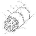
- FIG. 4A illustrates a perspective view of an example cable 400 including a segmented shield, according to an illustrative embodiment of the disclosure.
- the cable 400 may include components that are similar to the cables 100 , 200 , 300 illustrated in FIGS. 1-3 .
- FIG. 4A illustrates an example cable 400 in which an overall shield encloses a plurality of transmission media (e.g., twisted pairs, etc.); however, in other embodiments, shields may be formed to enclose individual transmission media and/or any desired grouping of transmission media.
- the cable 400 may include any number of transmission media situated within a cable core. As illustrated, the cable 400 may include four twisted pairs 405 , although other transmission media or combinations of transmission media may be utilized.
- a separator 410 or filler may be positioned between two or more of the twisted pairs 405 .
- one or more shields may be incorporated into the cable 400 .
- an overall shield 420 may be formed around the four twisted pairs 405 .
- a twisted pair may be individually shielded and/or desired subgroups of twisted pairs may be shielded.
- the shield 420 may be formed from a plurality of longitudinally extending segments, such as segments 420 A, 420 B. 420 C.
- Each segment 420 A, 420 B, 420 C may include one or more patches of electrically conductive material, such as metallic patches formed on a suitable carrier or substrate layer.
- an overlap may be formed between each adjacent shield segment 420 A, 420 B, 420 C.
- a first shield segment 420 A may be formed around the twisted pairs 405 , and the first shield segment 420 A may include a first end and a second end along a longitudinal direction of the cable 400 .
- a second shield segment 420 B may be formed around the twisted pairs 405 , and the second shield segment 420 B may also include a first end and a second end. The first end of the second shield segment 420 B may overlap the second end of the first shield segment 420 A. As desired, a third shield segment 420 C may also be formed around the twisted pairs 405 , and a first end of the third shield segment 420 C may overlap the second end of the second shield segment 420 B. Any number of other shield segments may be formed in a similar manner.
- segment overlapping configurations may be utilized as desired in various embodiments.
- both the first segment 420 A and the third segment 420 C may overlap the second segment 420 B.
- overlapping configurations is possible and will be appreciated by those of ordinary skill in the art.
- individual shield segments 420 A-C may be separately wrapped around the twisted pairs 405 such that adjacent shield segments overlap one another.
- individual shield segments may be incorporated into a cable during cable construction.
- a shield 420 may be formed from a plurality of overlapping segments 420 A-C, and the formed shield 420 may be wrapped around the twisted pairs 405 .
- individual segments may be combined in an overlapping fashion, and the resulting shield may then be incorporated into a cable during cable construction.
- the cable 400 illustrated in FIG. 4A may include a wide variety of other components as desired in various embodiments.
- the cable 400 may include an outside jacket that is formed over the shield 420 .
- the cable 400 may include any combination of the example components described above with reference to FIGS. 1-3 .
- FIG. 4B illustrates one example technique for wrapping one or more twisted pairs 405 , which may be similar to the twisted pairs 105 illustrated in FIG. 1 , with a shield layer 420 , which may be similar to the shield 120 illustrated in FIG. 1 .
- one or more twisted pairs 405 may be positioned adjacent to a shield layer 420 (e.g., a shield layer formed from a plurality of overlapping segments).
- one or more twisted pairs 405 may be positioned adjacent to one or more shield layer segments, such as segments 420 A and 420 B.
- the twisted pair(s) 405 may extend essentially parallel with the major or longitudinal axis/dimension of the shield layer 420 or the segment(s). Thus, the twisted pair(s) 405 can be viewed as being parallel to the surface or plane of the shield layer 420 of segment(s). As desired, the twisted pair(s) 405 may be approximately centered along a width dimension of the shield layer 220 or segment(s). Alternatively, the twisted pair(s) 405 may be positioned closer to one edge of the shield layer 420 or segment(s).
- two conductors which are typically individually insulated, will be twisted together to form a twisted pair 405 .
- the shield layer 420 and/or various individual segments may then be wrapped around the twisted pair.
- the shield layer 420 and/or various segments may be wrapped around multiple twisted pairs of conductors, such as twisted pairs that have been twisted, bunched, or cabled together.
- one edge (or both edges) of the shield layer 420 may be brought up over the twisted pair(s) 405 , thereby encasing the twisted pair(s) 405 or wrapping the shield layer 420 around or over the twisted pair(s) 405 .
- the motion can be characterized as folding or curling the shield layer over the twisted pair(s) 405 .
- the individual segments may be wrapped so as to overlap one another.
- a first shield segment 420 A may be wrapped around the twisted pair(s) 205 .
- a second shield segment 420 B may then be wrapped around the twisted pairs 205 , and the second shield segment 420 B may overlap the first shield segment 420 A at one end or edge.
- a third shield segment 420 C may also be wrapped around the twisted pair(s) 405 , and the third shield segment 420 C may overlap the second shield segment 220 B. Any number of other shield segments may be wrapped around the twisted pair(s) 405 in a similar manner.
- the shield layer 420 may be wrapped around the twisted pair(s) 405 without substantially spiraling the shield layer 420 around or about the twisted pair(s) 405 .
- the shield layer 420 (or individual shield layer segments) may be wrapped so as to spiral around the twisted pair(s) 405 .
- the conductive patches included in the shield layer 420 may face away from the twisted pair(s) 405 , towards the exterior of a cable. In other embodiments, the conductive patches may face inward, towards the twisted pair(s) 405 . In yet other embodiments, conductive patches may be formed on both sides of the shield layer 420 .
- a shield layer 420 and the twisted pair(s) 205 are continuously fed from reels, bins, containers, or other bulk storage facilities into a narrowing chute or a funnel that curls the shield layer over the twisted pair(s).
- a relatively continuous shield layer 420 e.g., a shield layer that has been pre-formed to include overlapping segments
- a shield layer material e.g., a tape, etc.
- multiple sources of shield layer material may be provided.
- a nozzle or outlet port Downstream from the mechanism(s) (or as a component of this mechanism) that feed cable core components, a nozzle or outlet port can extrude a polymeric jacket, skin, casing, or sheath over the shield layer 420 , thus providing the basic architecture depicted in FIGS. 1-3 and discussed above.
- one or more of the electrically conductive patches included in a shield may be shorted in a circumferential direction or along a periphery of the enclosed cable components.
- an electrically conductive patch may contact itself at the edges of a shield (or at any other desired point(s)) once the shield is wrapped around one or more twisted pairs (and/or other cable components).
- FIGS. 5A-5D illustrate a few example techniques for creating electrically shorted patches within a shield, according to illustrative embodiments of the disclosure.
- the illustrated shield 500 may include a dielectric material 505 , and one or more electrically conductive patches 510 may be formed on the dielectric material 505 .
- a fold 515 may be formed at or near one edge of the shield 500 .
- the shield 500 may be folded over itself along one edge (e.g., an edge in the width direction) or along one or more portions of one edge (e.g., portions of an edge corresponding to electrically conductive patches).
- the shield 500 when the shield 500 is wrapped around one or more twisted pairs (and/or other cable components) and brought into contact with itself within an overlapping region, the patch material at one edge of the shield 500 will be brought into contact with the patch material at or near the opposing edge of the shield 500 .
- FIG. 5B illustrates another example shield 520 and associated overlap portion.
- the shield 520 may include a dielectric material 525 , and one or more electrically conductive patches 530 may be formed on the dielectric material 525 .
- an overhanging portion 530 may be formed in which electrically conductive patch material extends beyond the dielectric material 525 .
- suitable techniques may be utilized as desired to form the overhanging portion 530 .
- the dielectric material 525 may be removed from one edge (or a portion of one edge) of the shield 520 .
- one or more electrically conductive patches 530 may be formed on or attached to the dielectric material 525 so as to overhang or extend beyond one edge (or one or more portions of one edge) of the dielectric material 525 . Accordingly, when the shield 520 is wrapped around one or more twisted pairs (and/or other cable components) and brought into contact with itself, the two edges (or a first edge and another portion) of an electrically conductive patch 530 will be brought into contact with one another, thereby creating an electrically shorted patch.
- FIG. 5C illustrates another example shield 540 and associated overlap portion in which electrically shorted patches may be formed.
- the shield 540 may include a dielectric material 545 , and one or more electrically conductive patches 550 may be formed on the dielectric material 545 .
- one or more vias 555 e.g., metallic or electrically conductive vias, etc.
- one or more gaps or holes may be formed in the dielectric material 545 .
- one edge of an electrically conductive patch may be permitted to contact another edge of the patch via the one or more gaps or holes.
- FIG. 5D illustrates another example shield 560 and associated overlap portion in which electrically shorted patches may be formed.
- the shield 560 may include a dielectric material 565 , and one or more electrically conductive patches 570 may be formed on the dielectric material 565 .
- a patch 570 may include an overlapping or double-sided portion 575 at one edge (or at one or more portions of one edge) of the shield 560 .
- the patch 570 may be folded over one edge of the dielectric material 565 .
- the patch 570 may be formed on both sides of the dielectric material 565 along one edge (or at one or more portions of one edge) of the shield 560 .
- an electrically conductive patch 570 may be present on both sides of the dielectric material 565 . Accordingly, when the shield 560 is wrapped around one or more twisted pairs (and/or other cable components) and brought into contact with itself, the patch 570 will be electrically shorted.
- one or more discontinuous patches may be formed along a length of the cable without a carrier tape or other substrate.
- a plurality of discontinuous patches may be wrapped or otherwise formed around one or more twisted pairs or other transmission media. Any number of suitable techniques may be utilized as desired to hold the patches in place.
- an adhesive e.g., a contact adhesive, a pressure sensitive adhesive, a hot melt adhesive
- a patch may be applied to a patch in order to adhere the patch to the transmission media, an inner surface of an outside cable jacket, and/or to any other desired components of a cable (e.g., an armor layer, a water-blocking layer, a tube, etc.).
- FIGS. 6A-6B illustrate cross-sections for example shield segments that may be utilized to form shields in accordance with various embodiments of the disclosure, such as the shield 120 illustrated in FIG. 1 .
- FIG. 6A illustrates a first example shield segment 600 that may be utilized in an overlapping shield.
- the shield segment 600 may be formed as a tape or other configuration including a substrate or carrier layer with electrically conductive material formed on the substrate.
- the segment 600 may include a dielectric layer 610 , and an electrically conductive layer 605 may be formed or disposed on one side of the dielectric layer 610 . As shown, the electrically conductive layer 605 may cover substantially all of one side of the dielectric layer 610 .
- the electrically conductive layer 605 may include any number of patches of electrically conductive material formed on the dielectric layer 610 . As desired, additional patches of electrically conductive material may be formed on an opposite side of the dielectric layer 610 to cover gaps between adjacent patches.
- FIG. 6B illustrates another example shield 615 in which an electrically conductive layer 620 is sandwiched between two dielectric layers 625 , 630 .
- a wide variety of other constructions may be utilized as desired to form a shield segment in accordance with various embodiments of the disclosure. Indeed, any number of dielectric and electrically conductive layers may be utilized.
- the shield segments 600 , 615 illustrated in FIGS. 6A-6B are provided by way of example only.
- FIGS. 7A-7D illustrate example electrically conductive patch configurations that may be utilized to form a shield segment in accordance with various embodiments of the disclosure, such as one or more shield segments incorporated into the shield 120 illustrated in FIG. 1 .
- a top level (or bottom level) view of a first example shield segment 700 is illustrated.
- the shield segment 700 may include a relatively continuous electrically conductive patch 705 formed on a dielectric material.
- the patch 705 may cover all or substantially all of one side of the dielectric material.
- the shield segment 700 may be incorporated into an overlapping discontinuous shield.
- the patch 705 may be circumferentially shorted utilizing any number of the techniques described herein.
- the shield segment 710 may include any number of rectangular patches of electrically conductive material, such as patches 715 A-D, formed on a dielectric material.
- the patches 715 A-D may include any desired lengths (e.g., approximately 2 meters, etc.), and any desired gap 720 or separation distance may be provided between adjacent patches.
- the patches may be formed in accordance with a repeating pattern having a definite step or period. As desired, additional patches may be formed on an opposing side of the dielectric material to cover the gaps 720 .
- each patch 715 A-D may have a width that extends from one edge of the shield segment 710 to an opposing edge of the shield segment 710 .
- the patches 715 A-D may be circumferentially shorted utilizing any number of the techniques described herein.
- FIG. 7C illustrates a top level (or bottom level) view of a third example shield segment 730 .
- the shield segment 730 may include any number of electrically conductive patches having the shape of a parallelogram. In other words, the patches may be formed at an angle along the shield segment. As shown, the patches may be formed at an acute angle with respect to the width dimension of the tape. In certain embodiments, the acute angle facilitates manufacturing and enhances patch-to-substrate adhesion.
- the acute angle may also facilitate the covering of opposing isolating spaces or gaps.
- the acute angle results in the isolating spaces being oriented at a non-perpendicular angle with respect to the pairs and the longitudinal axis of the cable. If any manufacturing issue results in part of the isolating spaces not being completely covered (e.g., by a conductive patch on an opposite tape side), such an open area will likewise be oriented at a non-perpendicular angle with respect to the pairs. Such an opening will therefore spiral about the pairs, rather than circumscribing a single longitudinal location of the cable. Such a spiraling opening is believed to have a lesser impact on shielding than would an opening circumscribing a single longitudinal location.
- benefit is achieved when the acute angle is about 45 degrees or less. In other embodiments, benefit is achieved when the acute angle is about 35 degrees or less, about 30 degrees or less, about 25 degrees or less, about 20 degrees or less, or about 15 degrees or less. In other embodiments, benefit is achieved when the acute angle is between about 12 and 40 degrees. In certain embodiments, the acute angle may be in a range between any two of the degree values provided in this paragraph.
- FIG. 7D illustrates a top level (or bottom level) view of a fourth example shield segment 740 .
- the shield segment 740 may include any number of electrically conductive patches having a trapezoidal shape. In certain embodiments, the orientation of adjacent trapezoidal patches may alternate. Similar to the patch pattern illustrated in FIG. 7C , the trapezoidal patches may provide manufacturing and/or shielding benefits. A wide variety of other suitable patch configurations may be utilized as desired in various embodiments.
- Conditional language such as, among others, “can,” “could,” “might,” or “may,” unless specifically stated otherwise, or otherwise understood within the context as used, is generally intended to convey that certain embodiments could include, while other embodiments do not include, certain features, elements, and/or operations. Thus, such conditional language is not generally intended to imply that features, elements, and/or operations are in any way required for one or more embodiments or that one or more embodiments necessarily include logic for deciding, with or without user input or prompting, whether these features, elements, and/or operations are included or are to be performed in any particular embodiment.
Abstract
Description
Claims (20)
Priority Applications (2)
| Application Number | Priority Date | Filing Date | Title |
|---|---|---|---|
| US13/827,359 US9251930B1 (en) | 2006-08-11 | 2013-03-14 | Segmented shields for use in communication cables |
| US14/578,921 US9275776B1 (en) | 2006-08-11 | 2014-12-22 | Shielding elements for use in communication cables |
Applications Claiming Priority (7)
| Application Number | Priority Date | Filing Date | Title |
|---|---|---|---|
| US50277706A | 2006-08-11 | 2006-08-11 | |
| US65380408A | 2008-12-19 | 2008-12-19 | |
| US13/039,918 US8395045B2 (en) | 2006-08-11 | 2011-03-03 | Communication cable comprising electrically discontinuous shield having nonmetallic appearance |
| US13/039,923 US8492648B2 (en) | 2006-08-11 | 2011-03-03 | Communication cable comprising electrically discontinuous shield having nonmetallic appearance |
| US201361754812P | 2013-01-21 | 2013-01-21 | |
| US201313827257A | 2013-03-14 | 2013-03-14 | |
| US13/827,359 US9251930B1 (en) | 2006-08-11 | 2013-03-14 | Segmented shields for use in communication cables |
Related Child Applications (1)
| Application Number | Title | Priority Date | Filing Date |
|---|---|---|---|
| US14/578,921 Continuation-In-Part US9275776B1 (en) | 2006-08-11 | 2014-12-22 | Shielding elements for use in communication cables |
Publications (1)
| Publication Number | Publication Date |
|---|---|
| US9251930B1 true US9251930B1 (en) | 2016-02-02 |
Family
ID=55175024
Family Applications (1)
| Application Number | Title | Priority Date | Filing Date |
|---|---|---|---|
| US13/827,359 Active US9251930B1 (en) | 2006-08-11 | 2013-03-14 | Segmented shields for use in communication cables |
Country Status (1)
| Country | Link |
|---|---|
| US (1) | US9251930B1 (en) |
Cited By (13)
| Publication number | Priority date | Publication date | Assignee | Title |
|---|---|---|---|---|
| US20160172794A1 (en) * | 2013-03-15 | 2016-06-16 | Leviton Manufacturing Co., Inc. | Communications connector system |
| US20170017004A1 (en) * | 2014-03-13 | 2017-01-19 | Afl Telecommunications Llc | Cable for land based seismic array system |
| CN106448914A (en) * | 2016-12-15 | 2017-02-22 | 江苏戴普科技有限公司 | Rail transit flame-retardant four-pair shielded twisted-pair |
| CN106448913A (en) * | 2016-12-15 | 2017-02-22 | 江苏戴普科技有限公司 | Double joint cable for rail traffic |
| US9831606B2 (en) | 2015-10-14 | 2017-11-28 | Leviton Manufacturing Co., Inc. | Communication connector |
| USD818469S1 (en) | 2014-06-19 | 2018-05-22 | Leviton Manufacturing Co., Inc. | Communication outlet |
| US10135207B2 (en) | 2016-01-31 | 2018-11-20 | Leviton Manufacturing Co., Inc. | High-speed data communications connector |
| US10186350B2 (en) | 2016-07-26 | 2019-01-22 | General Cable Technologies Corporation | Cable having shielding tape with conductive shielding segments |
| US10517198B1 (en) | 2018-06-14 | 2019-12-24 | General Cable Technologies Corporation | Cable having shielding tape with conductive shielding segments |
| US20200043634A1 (en) * | 2015-03-26 | 2020-02-06 | Paige Electric Company, Lp | Cable For Power-Over-Ethernet Having An Extended Usable Length |
| US20200126692A1 (en) * | 2017-09-28 | 2020-04-23 | Sterlite Technologies Limited | I-shaped filler |
| US11242596B2 (en) * | 2017-06-08 | 2022-02-08 | Boe Technology Group Co., Ltd. | Film forming method |
| US11322275B2 (en) | 2019-01-18 | 2022-05-03 | Comtran Cable Llc | Flame resistant data cables and related methods |
Citations (50)
| Publication number | Priority date | Publication date | Assignee | Title |
|---|---|---|---|---|
| US2796463A (en) | 1951-06-29 | 1957-06-18 | Bell Telephone Labor Inc | Composite conductors |
| US3090825A (en) | 1959-12-29 | 1963-05-21 | Anaconda Wire & Cable Co | Insulated cable |
| US3135935A (en) | 1962-10-02 | 1964-06-02 | Bell Telephone Labor Inc | Transmission line and method of making |
| US3312774A (en) | 1965-02-10 | 1967-04-04 | John D Drinko | Semi-insulating shielding for cables and the like and comprising discrete "floating"patches of semi-conductive material |
| US3373475A (en) | 1966-03-07 | 1968-03-19 | Western Electric Co | Apparatus for folding tape about a strand |
| US3612744A (en) | 1969-02-27 | 1971-10-12 | Hughes Aircraft Co | Flexible flat conductor cable of variable electrical characteristics |
| US4129841A (en) | 1976-08-13 | 1978-12-12 | Kabel-Und Metallwerke Gutehoffnungshutte A.G. | Radiating cable having spaced radiating sleeves |
| US4327246A (en) | 1980-02-19 | 1982-04-27 | Belden Corporation | Electric cables with improved shielding members |
| US4604497A (en) | 1983-07-28 | 1986-08-05 | Northern Telecom Limited | Electrical conductor for telecommunications cable |
| US4638272A (en) | 1983-05-05 | 1987-01-20 | The Commonwealth Of Australia | Lossy transmission line using spaced ferrite beads |
| US4746767A (en) | 1987-02-27 | 1988-05-24 | Neptco Incorporated | Shielded electrical cable construction |
| US4881642A (en) | 1988-12-08 | 1989-11-21 | Adam William D | Electrostatic charge dissipator and method of making |
| US4912283A (en) | 1988-01-05 | 1990-03-27 | Kt Technologies Inc. | Shielding tape for telecommunications cables and a cable including same |
| US5006806A (en) | 1989-03-15 | 1991-04-09 | Schonstedt Instrument Company | Methods and apparatus employing permanent magnets for marking, locating, tracing and identifying hidden objects such as burried fiber optic cables |
| US5008489A (en) | 1989-10-25 | 1991-04-16 | Facile Holdings, Inc. | Electrical cables and serpentine pattern shielding tape therefor |
| US5106175A (en) | 1989-12-28 | 1992-04-21 | At&T Bell Laboratories | Locatable object suitable for underground use and methods of locating same |
| US5114517A (en) | 1989-10-30 | 1992-05-19 | Schonstedt Instrument Company | Methods, apparatus and devices relating to magnetic markers for elongated hidden objects |
| US5473336A (en) | 1992-10-08 | 1995-12-05 | Auratek Security Inc. | Cable for use as a distributed antenna |
| US5952615A (en) | 1995-09-15 | 1999-09-14 | Filotex | Multiple pair cable with individually shielded pairs that is easy to connect |
| US5956445A (en) | 1994-05-20 | 1999-09-21 | Belden Wire & Cable Company | Plenum rated cables and shielding tape |
| JP2000090748A (en) | 1998-09-10 | 2000-03-31 | Showa Electric Wire & Cable Co Ltd | Cable with shield |
| US6207901B1 (en) * | 1999-04-01 | 2001-03-27 | Trw Inc. | Low loss thermal block RF cable and method for forming RF cable |
| US6506976B1 (en) | 1999-09-14 | 2003-01-14 | Avaya Technology Corp. | Electrical cable apparatus and method for making |
| US6677518B2 (en) | 2002-02-08 | 2004-01-13 | Sumitomo Electric Industries, Ltd. | Data transmission cable |
| US6687437B1 (en) | 2000-06-05 | 2004-02-03 | Essex Group, Inc. | Hybrid data communications cable |
| US6723925B2 (en) | 2001-12-03 | 2004-04-20 | The Furukawa Electric Co., Ltd. | Flat cable and laminated cable harness |
| US6737574B2 (en) | 2002-07-25 | 2004-05-18 | Neptco Incorporated | Detectable cable tape |
| US6770819B2 (en) | 2002-02-12 | 2004-08-03 | Commscope, Properties Llc | Communications cables with oppositely twinned and bunched insulated conductors |
| US6831231B2 (en) | 2001-12-05 | 2004-12-14 | Times Microwave Systems, Division Of Smiths Aerospace, Incorporated | Coaxial cable with flat outer conductor |
| US6850161B1 (en) | 2000-10-23 | 2005-02-01 | Verizon Corporate Services Group Inc. | Systems and methods for identifying and mapping conduit location |
| US6888070B1 (en) | 1999-10-16 | 2005-05-03 | Raydex/Cdt Limited | Cables including fillers |
| US20060048961A1 (en) | 2004-09-03 | 2006-03-09 | Draka Comteq Germany Gmbh & Co. Kg | Multi-layer, strip-type screening sheet for electric lines and electric cable, in particular a data transmission cable, equipped therewith |
| JP2006173044A (en) | 2004-12-20 | 2006-06-29 | Furukawa Electric Co Ltd:The | Metal shield wire |
| WO2006105166A2 (en) | 2005-03-28 | 2006-10-05 | Leviton Manufacturing Co., Inc. | Discontinuous cable shield system and method |
| US7173189B1 (en) | 2005-11-04 | 2007-02-06 | Adc Telecommunications, Inc. | Concentric multi-pair cable with filler |
| US7179999B2 (en) | 1999-02-25 | 2007-02-20 | Belden Technologies, Inc. | Multi-pair data cable with configurable core filling and pair separation |
| GB2432963A (en) | 2005-12-01 | 2007-06-06 | Brand Rex Ltd | High frequency cable |
| US20070224495A1 (en) | 2006-03-22 | 2007-09-27 | Gibbons Daniel W | Zinc/air cell |
| US20070275583A1 (en) | 2006-05-17 | 2007-11-29 | Leviton Manufacturing Co., Inc. | Communication cabling with shielding separator system and method |
| US20080255435A1 (en) | 2007-04-16 | 2008-10-16 | Masimo Corporation | Low noise oximetry cable including conductive cords |
| US20080314636A1 (en) | 2007-06-19 | 2008-12-25 | Yazaki Corporation | Multi-layer shielded wire |
| US20090200060A1 (en) | 2006-08-11 | 2009-08-13 | Superior Essex Communications Lp | Communication cable comprising electrically discontinuous shield having nonmetallic appearance |
| US20090223694A1 (en) * | 2008-03-06 | 2009-09-10 | Panduit Corp. | Communication Cable with Improved Crosstalk Attenuation |
| US20090272571A1 (en) | 2008-04-30 | 2009-11-05 | Tyco Electronics Corporation | Cabling having shielding separators |
| US20100096179A1 (en) | 2006-05-17 | 2010-04-22 | Leviton Manufacturing Co., Inc. | Communication cabling with shielding separator and discontinuous cable shield |
| US20100101853A1 (en) | 2006-08-11 | 2010-04-29 | Superior Essex Communications Lp | Communication cable having electrically isolated shield providing enhanced return loss |
| US20100224389A1 (en) | 2009-03-03 | 2010-09-09 | Panduit Corp. | Method and Apparatus For Manufacturing Mosaic Tape For Use In Communication Cable |
| US7834270B2 (en) | 2008-07-07 | 2010-11-16 | Imris Inc. | Floating segmented shield cable assembly |
| US8119906B1 (en) | 2006-08-11 | 2012-02-21 | Superior Essex Communications, Lp | Communication cable shielded with mechanically fastened shielding elements |
| US8445787B2 (en) | 2009-05-06 | 2013-05-21 | Panduit Corp. | Communication cable with improved electrical characteristics |
-
2013
- 2013-03-14 US US13/827,359 patent/US9251930B1/en active Active
Patent Citations (56)
| Publication number | Priority date | Publication date | Assignee | Title |
|---|---|---|---|---|
| US2796463A (en) | 1951-06-29 | 1957-06-18 | Bell Telephone Labor Inc | Composite conductors |
| US3090825A (en) | 1959-12-29 | 1963-05-21 | Anaconda Wire & Cable Co | Insulated cable |
| US3135935A (en) | 1962-10-02 | 1964-06-02 | Bell Telephone Labor Inc | Transmission line and method of making |
| US3312774A (en) | 1965-02-10 | 1967-04-04 | John D Drinko | Semi-insulating shielding for cables and the like and comprising discrete "floating"patches of semi-conductive material |
| US3373475A (en) | 1966-03-07 | 1968-03-19 | Western Electric Co | Apparatus for folding tape about a strand |
| US3612744A (en) | 1969-02-27 | 1971-10-12 | Hughes Aircraft Co | Flexible flat conductor cable of variable electrical characteristics |
| US4129841A (en) | 1976-08-13 | 1978-12-12 | Kabel-Und Metallwerke Gutehoffnungshutte A.G. | Radiating cable having spaced radiating sleeves |
| US4327246A (en) | 1980-02-19 | 1982-04-27 | Belden Corporation | Electric cables with improved shielding members |
| US4638272A (en) | 1983-05-05 | 1987-01-20 | The Commonwealth Of Australia | Lossy transmission line using spaced ferrite beads |
| US4604497A (en) | 1983-07-28 | 1986-08-05 | Northern Telecom Limited | Electrical conductor for telecommunications cable |
| US4746767A (en) | 1987-02-27 | 1988-05-24 | Neptco Incorporated | Shielded electrical cable construction |
| US4912283A (en) | 1988-01-05 | 1990-03-27 | Kt Technologies Inc. | Shielding tape for telecommunications cables and a cable including same |
| US4881642A (en) | 1988-12-08 | 1989-11-21 | Adam William D | Electrostatic charge dissipator and method of making |
| US5006806A (en) | 1989-03-15 | 1991-04-09 | Schonstedt Instrument Company | Methods and apparatus employing permanent magnets for marking, locating, tracing and identifying hidden objects such as burried fiber optic cables |
| US5008489A (en) | 1989-10-25 | 1991-04-16 | Facile Holdings, Inc. | Electrical cables and serpentine pattern shielding tape therefor |
| US5114517A (en) | 1989-10-30 | 1992-05-19 | Schonstedt Instrument Company | Methods, apparatus and devices relating to magnetic markers for elongated hidden objects |
| US5106175A (en) | 1989-12-28 | 1992-04-21 | At&T Bell Laboratories | Locatable object suitable for underground use and methods of locating same |
| US5473336A (en) | 1992-10-08 | 1995-12-05 | Auratek Security Inc. | Cable for use as a distributed antenna |
| US5956445A (en) | 1994-05-20 | 1999-09-21 | Belden Wire & Cable Company | Plenum rated cables and shielding tape |
| US5952615A (en) | 1995-09-15 | 1999-09-14 | Filotex | Multiple pair cable with individually shielded pairs that is easy to connect |
| JP2000090748A (en) | 1998-09-10 | 2000-03-31 | Showa Electric Wire & Cable Co Ltd | Cable with shield |
| US7179999B2 (en) | 1999-02-25 | 2007-02-20 | Belden Technologies, Inc. | Multi-pair data cable with configurable core filling and pair separation |
| US6207901B1 (en) * | 1999-04-01 | 2001-03-27 | Trw Inc. | Low loss thermal block RF cable and method for forming RF cable |
| US6506976B1 (en) | 1999-09-14 | 2003-01-14 | Avaya Technology Corp. | Electrical cable apparatus and method for making |
| US6888070B1 (en) | 1999-10-16 | 2005-05-03 | Raydex/Cdt Limited | Cables including fillers |
| US6687437B1 (en) | 2000-06-05 | 2004-02-03 | Essex Group, Inc. | Hybrid data communications cable |
| US6850161B1 (en) | 2000-10-23 | 2005-02-01 | Verizon Corporate Services Group Inc. | Systems and methods for identifying and mapping conduit location |
| US6723925B2 (en) | 2001-12-03 | 2004-04-20 | The Furukawa Electric Co., Ltd. | Flat cable and laminated cable harness |
| US6831231B2 (en) | 2001-12-05 | 2004-12-14 | Times Microwave Systems, Division Of Smiths Aerospace, Incorporated | Coaxial cable with flat outer conductor |
| US6677518B2 (en) | 2002-02-08 | 2004-01-13 | Sumitomo Electric Industries, Ltd. | Data transmission cable |
| US6770819B2 (en) | 2002-02-12 | 2004-08-03 | Commscope, Properties Llc | Communications cables with oppositely twinned and bunched insulated conductors |
| US6737574B2 (en) | 2002-07-25 | 2004-05-18 | Neptco Incorporated | Detectable cable tape |
| US20060048961A1 (en) | 2004-09-03 | 2006-03-09 | Draka Comteq Germany Gmbh & Co. Kg | Multi-layer, strip-type screening sheet for electric lines and electric cable, in particular a data transmission cable, equipped therewith |
| US7335837B2 (en) * | 2004-09-03 | 2008-02-26 | Draka Comteq Germany Gmbh & Co. Kg | Multi-layer, strip-type screening sheet for electric lines and electric cable, in particular a data transmission cable, equipped therewith |
| JP2006173044A (en) | 2004-12-20 | 2006-06-29 | Furukawa Electric Co Ltd:The | Metal shield wire |
| US20070037419A1 (en) | 2005-03-28 | 2007-02-15 | Leviton Manufacturing Co., Inc. | Discontinued cable shield system and method |
| US7332676B2 (en) * | 2005-03-28 | 2008-02-19 | Leviton Manufacturing Co., Inc. | Discontinued cable shield system and method |
| WO2006105166A2 (en) | 2005-03-28 | 2006-10-05 | Leviton Manufacturing Co., Inc. | Discontinuous cable shield system and method |
| US7173189B1 (en) | 2005-11-04 | 2007-02-06 | Adc Telecommunications, Inc. | Concentric multi-pair cable with filler |
| GB2432963A (en) | 2005-12-01 | 2007-06-06 | Brand Rex Ltd | High frequency cable |
| US20070224495A1 (en) | 2006-03-22 | 2007-09-27 | Gibbons Daniel W | Zinc/air cell |
| US20100096179A1 (en) | 2006-05-17 | 2010-04-22 | Leviton Manufacturing Co., Inc. | Communication cabling with shielding separator and discontinuous cable shield |
| US20070275583A1 (en) | 2006-05-17 | 2007-11-29 | Leviton Manufacturing Co., Inc. | Communication cabling with shielding separator system and method |
| US7923632B2 (en) | 2006-08-11 | 2011-04-12 | Superior Essex Communications Lp | Communication cable comprising electrically discontinuous shield having nonmetallic appearance |
| US20090200060A1 (en) | 2006-08-11 | 2009-08-13 | Superior Essex Communications Lp | Communication cable comprising electrically discontinuous shield having nonmetallic appearance |
| US20100101853A1 (en) | 2006-08-11 | 2010-04-29 | Superior Essex Communications Lp | Communication cable having electrically isolated shield providing enhanced return loss |
| US20110147039A1 (en) | 2006-08-11 | 2011-06-23 | Superior Essex Communications Lp | Communication Cable Comprising Electrically Discontinuous Shield Having Nonmetallic Appearance |
| US8119906B1 (en) | 2006-08-11 | 2012-02-21 | Superior Essex Communications, Lp | Communication cable shielded with mechanically fastened shielding elements |
| US20080255435A1 (en) | 2007-04-16 | 2008-10-16 | Masimo Corporation | Low noise oximetry cable including conductive cords |
| US20080314636A1 (en) | 2007-06-19 | 2008-12-25 | Yazaki Corporation | Multi-layer shielded wire |
| US20090223694A1 (en) * | 2008-03-06 | 2009-09-10 | Panduit Corp. | Communication Cable with Improved Crosstalk Attenuation |
| US20090272571A1 (en) | 2008-04-30 | 2009-11-05 | Tyco Electronics Corporation | Cabling having shielding separators |
| US7834270B2 (en) | 2008-07-07 | 2010-11-16 | Imris Inc. | Floating segmented shield cable assembly |
| US20100224389A1 (en) | 2009-03-03 | 2010-09-09 | Panduit Corp. | Method and Apparatus For Manufacturing Mosaic Tape For Use In Communication Cable |
| US8558115B2 (en) | 2009-03-03 | 2013-10-15 | Panduit Corp. | Communication cable including a mosaic tape |
| US8445787B2 (en) | 2009-05-06 | 2013-05-21 | Panduit Corp. | Communication cable with improved electrical characteristics |
Non-Patent Citations (12)
| Title |
|---|
| "10 Gigabit Ethernet Solutions" 8pgs., R&M Convincing Cabling Solutions. |
| "Connections 29" 36 pgs., Sep. 2005. |
| "Draka" 12 pgs., Draka Comteq, Cable Solutions, Data cables, Sep. 27, 2006. |
| "Product Catalogue" 2 pages, Enterprise Cabling R&M, May 2006. |
| "R&M Star Real 10" 2pgs., Mar. 2006. |
| Non-Final Rejection for U.S. Appl. No. 13/827,257, mailed on Jan. 14, 2015. |
| Non-Final Rejection for U.S. Appl. No. 13/835,800, mailed on Feb. 19, 2015. |
| Notice of Allowance and Fee(s) Due in U.S. Appl. No. 14/578,921, mailed on Oct. 9, 2015. |
| Office Action, mailed Jul. 9, 2015, in the U.S. Appl. No. 13/835,800. |
| Office Action, mailed on Jul. 16, 2015, for U.S. Appl. No. 14/271,800. |
| Pfeiler et al., U.S. Pat. No. 7,335,837, issued Feb. 26, 2008. |
| Wetzikon, "R&M: The Rising Stars in Copper Cabling" 2pgs., Sep. 1, 2005. |
Cited By (23)
| Publication number | Priority date | Publication date | Assignee | Title |
|---|---|---|---|---|
| US9859663B2 (en) * | 2013-03-15 | 2018-01-02 | Leviton Manufacturing Co., Inc. | Communications connector system |
| US20160172794A1 (en) * | 2013-03-15 | 2016-06-16 | Leviton Manufacturing Co., Inc. | Communications connector system |
| US20170017004A1 (en) * | 2014-03-13 | 2017-01-19 | Afl Telecommunications Llc | Cable for land based seismic array system |
| US20190049607A1 (en) * | 2014-03-13 | 2019-02-14 | Afl Telecommunications Llc | Cable For Land Based Seismic Array Systems |
| USD848430S1 (en) | 2014-06-19 | 2019-05-14 | Leviton Manufacturing Co., Inc. | Communication outlet |
| USD818469S1 (en) | 2014-06-19 | 2018-05-22 | Leviton Manufacturing Co., Inc. | Communication outlet |
| USD901509S1 (en) | 2014-06-19 | 2020-11-10 | Leviton Manufacturing Co., Inc. | Communication outlet |
| US11107605B2 (en) * | 2015-03-26 | 2021-08-31 | Paige Electric Company, Lp | Cable for power-over-ethernet having an extended usable length |
| US20230162892A1 (en) * | 2015-03-26 | 2023-05-25 | Paige Electric Company, Lp | Cable For Power-Over-Ethernet Having An Extended Usable Length |
| US11646133B1 (en) * | 2015-03-26 | 2023-05-09 | Paige Electric Company, Lp | Cable for power-over-ethernet having an extended usable length |
| US20200043634A1 (en) * | 2015-03-26 | 2020-02-06 | Paige Electric Company, Lp | Cable For Power-Over-Ethernet Having An Extended Usable Length |
| US11562835B2 (en) * | 2015-03-26 | 2023-01-24 | Paige Electric Company, Lp | Cable for power-over-ethernet having an extended usable length |
| US20210350955A1 (en) * | 2015-03-26 | 2021-11-11 | Paige Electric Company, Lp | Cable For Power-Over-Ethernet Having An Extended Usable Length |
| US9831606B2 (en) | 2015-10-14 | 2017-11-28 | Leviton Manufacturing Co., Inc. | Communication connector |
| US10135207B2 (en) | 2016-01-31 | 2018-11-20 | Leviton Manufacturing Co., Inc. | High-speed data communications connector |
| US10186350B2 (en) | 2016-07-26 | 2019-01-22 | General Cable Technologies Corporation | Cable having shielding tape with conductive shielding segments |
| CN106448913A (en) * | 2016-12-15 | 2017-02-22 | 江苏戴普科技有限公司 | Double joint cable for rail traffic |
| CN106448914A (en) * | 2016-12-15 | 2017-02-22 | 江苏戴普科技有限公司 | Rail transit flame-retardant four-pair shielded twisted-pair |
| US11242596B2 (en) * | 2017-06-08 | 2022-02-08 | Boe Technology Group Co., Ltd. | Film forming method |
| US10950368B2 (en) * | 2017-09-28 | 2021-03-16 | Sterlite Technologies Limited | I-shaped filler |
| US20200126692A1 (en) * | 2017-09-28 | 2020-04-23 | Sterlite Technologies Limited | I-shaped filler |
| US10517198B1 (en) | 2018-06-14 | 2019-12-24 | General Cable Technologies Corporation | Cable having shielding tape with conductive shielding segments |
| US11322275B2 (en) | 2019-01-18 | 2022-05-03 | Comtran Cable Llc | Flame resistant data cables and related methods |
Similar Documents
| Publication | Publication Date | Title |
|---|---|---|
| US9251930B1 (en) | Segmented shields for use in communication cables | |
| US9659686B1 (en) | Communication cables incorporating twisted pair separators that function as shields | |
| US10121571B1 (en) | Communications cables incorporating separator structures | |
| US9275776B1 (en) | Shielding elements for use in communication cables | |
| US9424964B1 (en) | Shields containing microcuts for use in communications cables | |
| US10388434B1 (en) | Twisted pair communication cables having separators formed from a combination of foamed and unfoamed materials | |
| US10249410B1 (en) | Power over ethernet twisted pair communication cables | |
| US10008307B1 (en) | High frequency shielded communications cables | |
| US6812408B2 (en) | Multi-pair data cable with configurable core filling and pair separation | |
| US9824794B1 (en) | Communication cables incorporating twisted pair separators with cooling channels | |
| CA2393811C (en) | A cable channel filler with imbedded shield and cable containing the same | |
| US9928943B1 (en) | Communication cables incorporating separator structures | |
| US9363935B1 (en) | Subdivided separation fillers for use in cables | |
| US10515743B1 (en) | Communication cables with separators having alternating projections | |
| US9099220B2 (en) | Flat type cable for high frequency applications | |
| US9390838B2 (en) | Shielded cable with UTP pair environment | |
| JP2004529468A (en) | Cable with twisted filler and common sheath | |
| US9922753B1 (en) | Communication cables with separators having bristles | |
| US9601233B1 (en) | Plenum rated twisted pair communication cables | |
| US20140262411A1 (en) | Extended curl s-shield | |
| US10276280B1 (en) | Power over ethernet twisted pair communications cables with a shield used as a return conductor | |
| US10593502B1 (en) | Fusible continuous shields for use in communication cables | |
| US8426732B1 (en) | Communication cable with improved member for positioning signal conductors | |
| US9741470B1 (en) | Communication cables incorporating separators with longitudinally spaced projections | |
| US10714232B1 (en) | Twisted pair communication cables with foamed PVDF jackets |
Legal Events
| Date | Code | Title | Description |
|---|---|---|---|
| AS | Assignment |
Owner name: BANK OF AMERICA, N.A., AS AGENT, GEORGIA Free format text: SECURITY AGREEMENT;ASSIGNORS:SUPERIOR ESSEX COMMUNICATIONS LP;ESSEX GROUP, INC.;REEL/FRAME:030611/0479 Effective date: 20130613 |
|
| STCF | Information on status: patent grant |
Free format text: PATENTED CASE |
|
| AS | Assignment |
Owner name: SUPERIOR ESSEX COMMUNICATIONS LP, GEORGIA Free format text: ASSIGNMENT OF ASSIGNORS INTEREST;ASSIGNOR:MCNUTT, CHRISTOPHER W.;REEL/FRAME:038337/0816 Effective date: 20130313 |
|
| AS | Assignment |
Owner name: BANK OF AMERICA, N.A., AS COLLATERAL AND ADMINISTR Free format text: SECURITY INTEREST;ASSIGNORS:SUPERIOR ESSEX INTERNATIONAL LP;ESSEX GROUP, INC.;ESSEX GROUP MEXICO INC.;REEL/FRAME:040132/0259 Effective date: 20160922 |
|
| AS | Assignment |
Owner name: SUPERIOR ESSEX INTERNATIONAL LP, GEORGIA Free format text: CHANGE OF NAME;ASSIGNOR:SUPERIOR ESSEX COMMUNICATIONS LP;REEL/FRAME:045039/0225 Effective date: 20131223 |
|
| MAFP | Maintenance fee payment |
Free format text: PAYMENT OF MAINTENANCE FEE, 4TH YEAR, LARGE ENTITY (ORIGINAL EVENT CODE: M1551); ENTITY STATUS OF PATENT OWNER: LARGE ENTITY Year of fee payment: 4 |
|
| AS | Assignment |
Owner name: BANK OF AMERICA, N.A., AS AGENT, GEORGIA Free format text: SECURITY INTEREST;ASSIGNORS:SUPERIOR ESSEX INTERNATIONAL LP;ESSEX BROWNELL LLC;REEL/FRAME:053968/0640 Effective date: 20201001 |
|
| AS | Assignment |
Owner name: SUPERIOR ESSEX INTERNATIONAL INC., GEORGIA Free format text: CHANGE OF NAME;ASSIGNOR:SUPERIOR ESSEX INTERNATIONAL LP;REEL/FRAME:063351/0561 Effective date: 20220928 |
|
| MAFP | Maintenance fee payment |
Free format text: PAYMENT OF MAINTENANCE FEE, 8TH YEAR, LARGE ENTITY (ORIGINAL EVENT CODE: M1552); ENTITY STATUS OF PATENT OWNER: LARGE ENTITY Year of fee payment: 8 |