US9274616B2 - Pointing error avoidance scheme - Google Patents
Pointing error avoidance scheme Download PDFInfo
- Publication number
- US9274616B2 US9274616B2 US13/813,339 US201213813339A US9274616B2 US 9274616 B2 US9274616 B2 US 9274616B2 US 201213813339 A US201213813339 A US 201213813339A US 9274616 B2 US9274616 B2 US 9274616B2
- Authority
- US
- United States
- Prior art keywords
- pointing
- location
- computing system
- time duration
- input device
- Prior art date
- Legal status (The legal status is an assumption and is not a legal conclusion. Google has not performed a legal analysis and makes no representation as to the accuracy of the status listed.)
- Expired - Fee Related, expires
Links
Images


Classifications
-
- G—PHYSICS
- G06—COMPUTING; CALCULATING OR COUNTING
- G06F—ELECTRIC DIGITAL DATA PROCESSING
- G06F3/00—Input arrangements for transferring data to be processed into a form capable of being handled by the computer; Output arrangements for transferring data from processing unit to output unit, e.g. interface arrangements
- G06F3/01—Input arrangements or combined input and output arrangements for interaction between user and computer
- G06F3/03—Arrangements for converting the position or the displacement of a member into a coded form
- G06F3/033—Pointing devices displaced or positioned by the user, e.g. mice, trackballs, pens or joysticks; Accessories therefor
-
- G—PHYSICS
- G06—COMPUTING; CALCULATING OR COUNTING
- G06F—ELECTRIC DIGITAL DATA PROCESSING
- G06F3/00—Input arrangements for transferring data to be processed into a form capable of being handled by the computer; Output arrangements for transferring data from processing unit to output unit, e.g. interface arrangements
- G06F3/01—Input arrangements or combined input and output arrangements for interaction between user and computer
- G06F3/02—Input arrangements using manually operated switches, e.g. using keyboards or dials
- G06F3/023—Arrangements for converting discrete items of information into a coded form, e.g. arrangements for interpreting keyboard generated codes as alphanumeric codes, operand codes or instruction codes
- G06F3/0233—Character input methods
- G06F3/0236—Character input methods using selection techniques to select from displayed items
-
- G—PHYSICS
- G06—COMPUTING; CALCULATING OR COUNTING
- G06F—ELECTRIC DIGITAL DATA PROCESSING
- G06F3/00—Input arrangements for transferring data to be processed into a form capable of being handled by the computer; Output arrangements for transferring data from processing unit to output unit, e.g. interface arrangements
- G06F3/01—Input arrangements or combined input and output arrangements for interaction between user and computer
- G06F3/03—Arrangements for converting the position or the displacement of a member into a coded form
- G06F3/033—Pointing devices displaced or positioned by the user, e.g. mice, trackballs, pens or joysticks; Accessories therefor
- G06F3/0354—Pointing devices displaced or positioned by the user, e.g. mice, trackballs, pens or joysticks; Accessories therefor with detection of 2D relative movements between the device, or an operating part thereof, and a plane or surface, e.g. 2D mice, trackballs, pens or pucks
- G06F3/03545—Pens or stylus
-
- G—PHYSICS
- G06—COMPUTING; CALCULATING OR COUNTING
- G06F—ELECTRIC DIGITAL DATA PROCESSING
- G06F3/00—Input arrangements for transferring data to be processed into a form capable of being handled by the computer; Output arrangements for transferring data from processing unit to output unit, e.g. interface arrangements
- G06F3/01—Input arrangements or combined input and output arrangements for interaction between user and computer
- G06F3/03—Arrangements for converting the position or the displacement of a member into a coded form
- G06F3/033—Pointing devices displaced or positioned by the user, e.g. mice, trackballs, pens or joysticks; Accessories therefor
- G06F3/038—Control and interface arrangements therefor, e.g. drivers or device-embedded control circuitry
Definitions
- the motion controller is widely used as a controller for video games or smart TVs.
- the motion controller uses an accelerometer to detect its approximate orientation and acceleration, and serves an image sensor, so it can be used as a pointing device.
- a user of the motion controller may move the motion controller to be directed to a desired location on a screen, and/or click a button for selecting an icon or a virtual key displayed at the location.
- a method performed under control of a computing system with a display may include detecting an input event applied to the computing system at a pointing location in a first area of the display, determining a first time duration for which the pointing location has been maintained in the first area, determining a second time duration for which the pointing location had been previously maintained in a previous area of the display before the pointing location moved into the first area, and determining an intended pointing location of the input event based at least in part on at least one of the first time duration and the second time duration.
- a computing system may include a pointing location tracking unit configured to track, in terms of time, a change of a pointing location to which an input device is directed, the input device interacting with the computing system; an input event detection unit configured to detect an input event applied from the input device to the computing system; and an intended pointing location determination unit configured to determine an intended pointing location of the input event detected by the input event detection unit, based at least in part on the change of the pointing location of the input device tracked by the pointing location tracking unit.
- a computer-readable storage medium may store thereon computer-executable instructions that, in response to execution, cause a computing system to perform operations, including: tracking, in terms of time, a change of a pointing location to which an input device is directed, the input device interacting with the computing system; detecting an input event applied from the input device to the computing system; and determining a user-intended pointing location of the input event based at least in part on the tracked change of the pointing location.
- FIG. 1 schematically shows an illustrative example of an environment in which an input device interacts with a computing system for performing operations in the computing system, arranged in accordance with at least some embodiments described herein;
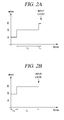
- FIGS. 2A and 2B show examples of diagrams illustrating a change of a pointing location in terms of time, arranged in accordance with at least some embodiments described herein;
- FIG. 3 shows a schematic block diagram illustrating an example architecture of a computing system for providing a pointing error avoidance scheme, arranged in accordance with at least some embodiments described herein;
- FIG. 4 shows an example flow diagram of a process for providing a pointing error avoidance scheme, arranged in accordance with at least some embodiments described herein;
- FIG. 5 illustrates example computer program products that may be utilized to provide a pointing error avoidance scheme, arranged in accordance with at least some embodiments described herein;
- FIG. 6 is a block diagram illustrating an example computing device that may be utilized to provide a pointing error avoidance scheme, arranged in accordance with at least some embodiments described herein.
- This disclosure is generally drawn, inter alia, to methods, apparatuses, systems, devices, and computer program products related to a pointing error avoidance scheme for a computing system. Further, technologies are herein generally described for a computing system configured to interact with an external pointing input device.
- the computing system may include a display configured to display a cursor moving corresponding to movement of the pointing input device. For example, when a user moves the pointing input device up, down, left and right, the cursor may move up, down, left and right accordingly.
- the user may use a button of the pointing input device to select an icon or a virtual key displayed on the display.
- the user may move the pointing input device so that the cursor on the display may hover a desired icon or virtual key.
- the user may then click the button to select the icon or virtual key over which the cursor hovers.
- the computing system may determine a pointing location of the pointing input device on a display when the user clicks the button, and determine an operation intended by the user who selects the icon or virtual key displayed at the pointing location. Then, the computing system may perform the operation associated with the selected icon or virtual key.
- the cursor when the user clicks the button, the cursor, which corresponds to the pointing location, may inadvertently move to a different icon or virtual key due to the user's hand moving. In such cases, the computing system may correct such a pointing error.
- the computing system may determine whether the cursor's location has changed from on a first key to on a second key simultaneously with or immediately prior to the user clicking the button on the pointing device.
- the computing system may determine that the user's intention was to select the first key, instead of the second key, although the user clicked the button when the cursor was hovering over the second key. That is, the computing system may determine an intended pointing location based at least in part on the change of the pointing location, using time as a basis for the determination.
- FIG. 1 schematically shows an illustrative example of an environment in which an input device interacts with a computing system for performing operations in the computing system, arranged in accordance with at least some embodiments described herein.
- a computing system 100 may include a console 110 , a display 120 , and an input device 130 .
- Examples of computing system 100 may include, but are not limited to, a smart TV, a video gaming system, and any other system that may receive an input from a user and provide the user with a requested output.
- the components of computing system 100 may be divided into additional components, or combined into fewer components, depending on the desired implementation.
- a user may use input device 130 to manipulate or control computing system 100 .
- input device 130 may interact or communicate with computing system 100 using short-range communication technologies including, for example, an infrared light signal, a radio signal, Bluetooth, etc.
- Examples of input device 130 may include, but are not limited to, a remote controller, a motion controller (e.g., Wii RemoteTM of Nintendo Co., Ltd.), and any other pointing input devices capable of interacting with computing system 100 .
- display 120 may display a virtual keyboard 140 and a text field 150 so that the user may enter text characters.
- display 120 may further display a cursor 160 , which may indicate a pointing location of input device 130 .
- the user may move input device 130 until cursor 160 hovers over one of virtual keys of virtual keyboard 140 corresponding to the character, and the user may then click a button 170 of input device 130 to select the desired virtual key.
- the user clicking button 170 may trigger an input event that may be detected by computing system 100 .
- Computing system 100 may also detect the pointing location to which input device 130 is directed at the time of the occurrence of the input event.
- computing system 100 may determine a first area of display 120 , within which the pointing location is located at the time of the occurrence of the input event. Then, in some embodiments, computing system 100 may determine whether the user's intended pointing location of the input event is within the first area or not.
- computing system 100 may measure a first time duration in which the pointing location has been maintained in the first area, and measure a second time duration for which the pointing location had been previously maintained in a previous area of display 120 before the pointing location moved into the first area. Then, computing system 100 may determine the intended pointing location of the input event based at least in part on the first time duration and/or the second time duration.
- An example process for determining the intended pointing location of the input event based at least in part on the first time duration and/or the second time duration will be described in more detail with reference to FIGS. 2A and 2B , which show examples of diagrams illustrating a change of a pointing location in terms of time, arranged in accordance with at least some embodiments described herein.
- computing system 100 may determine whether the intended pointing location of the input event is within the area of virtual key ‘D’, or within an area of another virtual key, based at least in part on a change of the pointing location prior to the input event.
- the pointing location was within an area of a virtual key ‘S’ before the pointing location moved into the area of virtual key ‘D’.
- computing system 100 may determine the first time duration for which the pointing location has been maintained in the area of virtual key ‘D’ (i.e., t 1 in FIGS. 2A and 2B ), and the second time duration for which the pointing location has been maintained in the area of virtual key ‘S’ (i.e., t 2 in FIGS. 2A and 2B ).
- computing system 100 may determine the intended pointing location of the input event based at least in part on a ratio of the first time duration to the second time duration (i.e., t 1 /t 2 in FIGS. 2A and 2B ). Referring to FIGS. 2A and 2B , computing system 100 may determine the intended pointing location of the input event as being located in the area of virtual key ‘S’ if the ratio (t 1 /t 2 ) is less than a predetermined value as in FIG. 2A , and determine the intended pointing location as being located in the area of virtual key ‘D’ if the ratio (t 1 /t 2 ) is greater than or equal to the predetermined value as in FIG. 2B .
- a ratio of the first time duration to the second time duration i.e., t 1 /t 2 in FIGS. 2A and 2B .
- the predetermined value may be associated with (e.g., set and/or updated at least in part on) empirical data analyzed from behavior of the user, including a usage pattern of the user. Further, if the usage pattern of the user indicates that an input error tends to occur when the ratio (t 1 /t 2 ) is less than 0.1, computing system 100 may set the predetermined value as 0.1 for the user. For example, the predetermined value may be set as one (1).
- computing system 100 may determine the intended pointing location of the input event based at least in part on the first time duration (i.e., t 1 in FIGS. 2A and 2B ). Referring to FIGS. 2A and 2B , computing system 100 may determine the intended pointing location of the input event as being located in the area of virtual key ‘S’ if the first time duration (t 1 ) is less than a predetermined amount of time as in FIG. 2A , and determine the intended pointing location as being located in the area of virtual key ‘D’ if the first time duration (t 1 ) is greater than or equal to the predetermined amount of time as in FIG. 2B .
- the predetermined amount of time may be associated with (e.g., set and/or updated at least in part on) empirical data analyzed from behavior of the user, including the user's usage pattern. Further, if the user's usage pattern indicates that an input error tends to occur when the first time duration (t 1 ) is less than 0.1 second, computing system 100 may set the predetermined amount of time as 0.1 second for the user.
- computing system 100 may determine the intended pointing location of the input event as being located in the area of virtual key ‘S’ if t 1 ⁇ t 2 + ⁇ as in FIG. 2A , and determine the intended pointing location as being located in the area of virtual key ‘D’ if t 1 ⁇ t 2 + ⁇ as in FIG. 2B .
- values of ⁇ and ⁇ may be associated with (e.g., set and/or updated at least in part on) empirical data analyzed from behavior of the user.
- display 120 may include a touch screen display.
- touching and/or gesturing on the touch screen display may trigger the input event.
- the user may touch the desired virtual key with his/her finger, and lift the finger from the display to select the corresponding character.
- computing system 100 may determine the intended pointing location of the input event based at least in part on a first time duration for which the finger has been maintained in a first area of the virtual key from which the user's finger is lifted and/or a second time duration for which the finger had been previously maintained in a previous area before the finger moved into the first area.
- computing system 100 may include a motion sensing input device (not shown) such as, for example, KinectTM of Microsoft Corporation.
- a motion sensing input device such as, for example, KinectTM of Microsoft Corporation.
- the user's motion may trigger the input event.
- the user may point one of the virtual keys of virtual keyboard 140 displayed on display 120 with his/her finger, and make a predetermined selecting gesture or speak a predetermined command for selecting the virtual key.
- computing system 100 may determine the intended pointing location of the input event based at least in part on a first time duration for which the finger has been maintained in a first area of the virtual key on which the user's selecting gesture and/or spoken command is captured and/or a second time duration for which the finger had been previously maintained in a previous area before the finger moved into the first area.
- FIGS. 1-2 illustrate the embodiments associated with virtual keyboard 140 displayed on display 120
- the scheme disclosed herein may be applied to any graphical user interface displayed on display 120
- computing system 100 performs operations including detecting the input event, determining the first and second time durations, determining the intended pointing location, and so on
- computing system 100 may perform operations including detecting the input event, determining the first and second time durations, determining the intended pointing location, and so on
- it may be an application run on computing system 100 , program modules of computing system 100 , and/or a cloud-based application accessed by computing system 100 that performs any operations described herein.
- FIG. 3 shows a schematic block diagram illustrating an example architecture of a computing system for providing a pointing error avoidance scheme, arranged in accordance with at least some embodiments described herein.
- computing system 100 may include a pointing location tracking unit 310 , an input event detection unit 320 , and an intended pointing location determination unit 330 .
- pointing location tracking unit 310 may include a pointing location tracking unit 310 , an input event detection unit 320 , and an intended pointing location determination unit 330 .
- Pointing location tracking unit 310 may be configured to track, in terms of time, a change of a pointing location to which an input device (e.g., input device 130 ) is directed.
- the pointing location may be a location on a display (e.g., display 120 ) of computing system 100 to which the input device is directed.
- Examples of the input device may include, but are not limited to, a remote controller, a motion controller, and any other pointing input devices capable of interacting with computing system 100 .
- Input event detection unit 320 may be configured to detect an input event applied from the input device to computing system 100 .
- the input event may be triggered by a user's action of clicking of a button (e.g., button 170 ) of the input device.
- Intended pointing location determination unit 330 may be configured to determine an intended pointing location of the input event detected by input event detection unit 320 , based at least in part on the change of the pointing location of the input device tracked by pointing location tracking unit 310 . In some embodiments, intended pointing location determination unit 330 may determine the intended pointing location of the input event based at least in part on a first time duration for which the pointing location has been maintained in a first area in which input event detection unit 320 detects the input event and/or a second time duration for which the pointing location had been maintained in a previous area before the pointing location moved into the first area.
- intended pointing location determination unit 330 may determine the intended pointing location of the input event as being located in the first area if a ratio of the first time duration to the second time duration is greater than or equal to a predetermined value, and determine the intended pointing location of the input event as being located in the previous area if the ratio of the first time duration to the second time duration is less than the predetermined value.
- the predetermined value may be associated with empirical data analyzed from behavior of the user.
- the predetermined value may be one (1).
- intended pointing location determination unit 330 may determine the intended pointing location of the input event being located in the first area if the first time duration is greater than or equal to a predetermined amount of time, and determine the intended pointing location of the input event as being located in the previous area if the first time duration is less than the predetermined amount of time.
- the predetermined amount of time may be associated with empirical data analyzed from behavior of the user.
- computing system 100 may avoid a potential pointing error due to the user's hand moving by inferring the users intended input based at least in part on the tracked change of the pointing location.
- FIG. 4 shows an example flow diagram of a process for providing a pointing error avoidance scheme, arranged in accordance with at least some embodiments described herein.
- the process in FIG. 4 may be implemented in a computing system, such as computing system 100 including pointing location tracking unit 310 , input event detection unit 320 and intended pointing location determination unit 330 , described above.
- An example process 400 may include one or more operations, actions, or functions as illustrated by one or more blocks 410 , 420 , 430 and/or 440 . Although illustrated as discrete blocks, various blocks may be divided into additional blocks, combined into fewer blocks, or eliminated, depending on the desired implementation. Processing may begin at block 410 .
- the computing system may detect an input event applied to the computing system at a pointing location in a first area of a display (e.g., display 120 ) of the computing system.
- the first area may be associated with a virtual key of a virtual keyboard or an icon displayed on the display.
- the computing system may be configured to receive an input signal from an external pointing input device (e.g., input device 130 ).
- the pointing location may be a location on the display to which the external pointing input device is directed, and the input event may be triggered by clicking of a button (e.g., button 170 ) of the external pointing input device.
- the display includes a touch screen display
- the input event may be triggered by the users touching and/or gesturing on the touch screen display.
- the computing system configures to receive the users input via a motion sensing input device (e.g., KinectTM of Microsoft Corporation), the input event may be triggered by the user's gesturing. Processing may continue from block 410 to block 420 .
- a motion sensing input device e.g., KinectTM of Microsoft Corporation
- the computing system may determine a first time duration for which the pointing location has been maintained in the first area. Processing may continue from block 420 to block 430 .
- the computing system may determine a second time duration for which the pointing location had been previously maintained in a previous area of the display before the pointing location moved into the first area. Processing may continue from block 430 to block 440 .
- the computing system may determine an intended pointing location of the input event based at least in part on at least one of the first time duration and the second time duration.
- the computing system may determine the intended pointing location of the input event as being located in the first area if a ratio of the first time duration to the second time duration is greater than or equal to a predetermined value, and determine the intended pointing location as being located in the previous area if the ratio of the first time duration to the second time duration is less than the predetermined value.
- the predetermined value may be associated with empirical data analyzed from behavior of the user.
- the predetermined value may be one (1).
- the computing system may determine the intended pointing location as being located in the first area if the first time duration is greater than or equal to a predetermined amount of time, and determine the intended pointing location as being located in the previous area if the first time duration is less than the predetermined amount of time.
- the predetermined amount of time may be associated with empirical data analyzed from behavior of the user.
- FIG. 5 illustrates example computer program products that may be utilized to provide a pointing error avoidance scheme, arranged in accordance with at least some embodiments described herein.
- Computer program product 500 may include a signal bearing medium 502 .
- Signal bearing medium 502 may include one or more instructions 504 that, when executed by, for example, a processor, may provide the functionality described above with respect to FIGS. 1-4 .
- instructions 504 may include: one or more instructions for tracking, in terms of time, a change of a pointing location to which an input device is directed, the input device interacting with a computing system; one or more instructions for detecting an input event applied from the input device to the computing system; or one or more instructions for determining a user-intended pointing location of the input event based at least in part on the tracked change of the pointing location.
- computing system 100 may undertake one or more of the blocks shown in FIG. 4 in response to instructions 504 .
- signal bearing medium 502 may encompass a computer-readable medium 506 , such as, but not limited to, a hard disk drive, a CD, a DVD, a digital tape, memory, etc.
- signal bearing medium 502 may encompass a recordable medium 508 , such as, but not limited to, memory, read/write (R/W) CDs, R/W DVDs, etc.
- signal bearing medium 502 may encompass a communications medium 510 , such as, but not limited to, a digital and/or an analog communication medium (e.g., a fiber optic cable, a waveguide, a wired communications link, a wireless communication link, etc.).
- computer program product 500 may be conveyed to one or more modules of computing system 100 by an RF signal bearing medium 502 , where the signal bearing medium 502 is conveyed by a wireless communications medium 510 (e.g., a wireless communications medium conforming with the IEEE 802.11 standard).
- a wireless communications medium 510 e.g., a wireless communications medium conforming with the IEEE 802.11 standard.
- FIG. 6 is a block diagram illustrating an example computing device that may be utilized to provide a pointing error avoidance scheme, arranged in accordance with at least some embodiments described herein.
- computing device 600 may be arranged or configured for computing system 100 .
- computing device 600 typically includes one or more processors 604 and a system memory 606 .
- a memory bus 608 may be used for communicating between processor 604 and system memory 606 .
- processor 604 may be of any type including but not limited to a microprocessor ( ⁇ P), a microcontroller C), a digital signal processor (DSP), or any combination thereof.
- Processor 604 may include one more levels of caching, such as a level one cache 610 and a level two cache 612 , a processor core 614 , and registers 616 .
- An example processor core 614 may include an arithmetic logic unit (ALU), a floating point unit (FPU), a digital signal processing core (DSP Core), or any combination thereof.
- An example memory controller 618 may also be used with processor 604 , or in some implementations memory controller 618 may be an internal part of processor 604 .
- system memory 606 may be of any type including but not limited to volatile memory (such as RAM), nonvolatile memory (such as ROM, flash memory, etc.) or any combination thereof.
- System memory 606 may include an operating system 620 , one or more applications 622 , and program data 624 .
- Application 622 may include instructions 626 that may be arranged to perform the functions as described herein including the actions described with respect to the computing system 100 architecture as shown in FIG. 3 or including the actions described with respect to the flow charts shown in FIG. 4 .
- application 622 may be arranged to operate with program data 624 on an operating system 620 such that implementations for instructions for a computing system as described herein.
- Computing device 600 may have additional features or functionality, and additional interfaces to facilitate communications between basic configuration 602 and any required devices and interfaces.
- a bus/interface controller 630 may be used to facilitate communications between basic configuration 602 and one or more data storage devices 632 via a storage interface bus 634 .
- Data storage devices 632 may be removable storage devices 636 , non-removable storage devices 638 , or a combination thereof. Examples of removable storage and non-removable storage devices include magnetic disk devices such as flexible disk drives and hard-disk drives (HDD), optical disk drives such as compact disk (CD) drives or digital versatile disk (DVD) drives, solid state drives (SSD), and tape drives to name a few.
- Example computer storage media may include volatile and nonvolatile, removable and non-removable media implemented in any method or technology for storage of information, such as computer readable instructions, data structures, program modules, or other data.
- Computer storage media includes, but is not limited to, RAM, ROM, EEPROM, flash memory or other memory technology, CD-ROM, digital versatile disks (DVD) or other optical storage, magnetic cassettes, magnetic tape, magnetic disk storage or other magnetic storage devices, or any other medium which may be used to store the desired information and which may be accessed by computing device 600 . Any such computer storage media may be part of computing device 600 .
- Computing device 600 may also include an interface bus 640 for facilitating communication from various interface devices (e.g., output devices 642 , peripheral interfaces 644 , and communication devices 646 ) to basic configuration 602 via bus/interface controller 630 .
- Example output devices 642 include a graphics processing unit 648 and an audio processing unit 650 , which may be configured to communicate to various external devices such as a display or speakers via one or more A/V ports 652 .
- Example peripheral interfaces 644 include a serial interface controller 654 or a parallel interface controller 656 , which may be configured to communicate with external devices such as input devices (e.g., keyboard, mouse, pen, voice input device, touch input device, etc.) or other peripheral devices (e.g., printer, scanner, etc.) via one or more I/O ports 658 .
- An example communication device 646 includes a network controller 660 , which may be arranged to facilitate communications with one or more other computing devices 662 over a network communication link via one or more communication ports 664 .
- the network communication link may be one example of a communication media.
- Communication media may typically be embodied by computer readable instructions, data structures, program modules, or other data in a modulated data signal, such as a carrier wave or other transport mechanism, and may include any information delivery media.
- a “modulated data signal” may be a signal that has one or more of its characteristics set or changed in such a manner as to encode information in the signal.
- communication media may include wired media such as a wired network or direct-wired connection, and wireless media such as acoustic, radio frequency (RF), microwave, infrared (IR) and other wireless media.
- RF radio frequency
- IR infrared
- the term computer readable media as used herein may include both storage media and communication media.
- Computing device 600 may be implemented as a portion of a small-form factor portable (or mobile) electronic device such as a cell phone, a personal data assistant (PDA), a personal media player device, a wireless web-watch device, a personal headset device, an application specific device, or a hybrid device that include any of the above functions.
- a small-form factor portable (or mobile) electronic device such as a cell phone, a personal data assistant (PDA), a personal media player device, a wireless web-watch device, a personal headset device, an application specific device, or a hybrid device that include any of the above functions.
- PDA personal data assistant
- Computing device 600 may also be implemented as a personal computer including both laptop computer and non-laptop computer configurations.
- a range includes each individual member.
- a group having 1-3 cells refers to groups having 1, 2, or 3 cells.
- a group having 1-5 cells refers to groups having 1, 2, 3, 4, or 5 cells, and so forth.
Abstract
Description
Claims (16)
Applications Claiming Priority (1)
| Application Number | Priority Date | Filing Date | Title |
|---|---|---|---|
| PCT/US2012/054614 WO2014042617A1 (en) | 2012-09-11 | 2012-09-11 | Pointing error avoidance scheme |
Publications (2)
| Publication Number | Publication Date |
|---|---|
| US20140071048A1 US20140071048A1 (en) | 2014-03-13 |
| US9274616B2 true US9274616B2 (en) | 2016-03-01 |
Family
ID=50232762
Family Applications (1)
| Application Number | Title | Priority Date | Filing Date |
|---|---|---|---|
| US13/813,339 Expired - Fee Related US9274616B2 (en) | 2012-09-11 | 2012-09-11 | Pointing error avoidance scheme |
Country Status (2)
| Country | Link |
|---|---|
| US (1) | US9274616B2 (en) |
| WO (1) | WO2014042617A1 (en) |
Families Citing this family (1)
| Publication number | Priority date | Publication date | Assignee | Title |
|---|---|---|---|---|
| WO2015025874A1 (en) * | 2013-08-20 | 2015-02-26 | 株式会社ソニー・コンピュータエンタテインメント | Cursor location control device, cursor location control method, program, and information storage medium |
Citations (10)
| Publication number | Priority date | Publication date | Assignee | Title |
|---|---|---|---|---|
| US6177926B1 (en) | 1996-10-22 | 2001-01-23 | Intermec Ip Corp. | Hand-held computer having input screen and means for preventing inadvertent actuation of keys |
| US6295052B1 (en) | 1996-02-19 | 2001-09-25 | Misawa Homes Co., Ltd. | Screen display key input unit |
| US6295049B1 (en) | 1999-03-03 | 2001-09-25 | Richard T. Minner | Computer system utilizing graphical user interface with hysteresis to inhibit accidental selection of a region due to unintended cursor motion and method |
| US7614008B2 (en) | 2004-07-30 | 2009-11-03 | Apple Inc. | Operation of a computer with touch screen interface |
| US20100123659A1 (en) | 2008-11-19 | 2010-05-20 | Microsoft Corporation | In-air cursor control |
| US20100141577A1 (en) * | 2008-12-04 | 2010-06-10 | Seiko Epson Corporation | Pointing device, data processing device, and data processing system |
| US20100141606A1 (en) * | 2008-12-08 | 2010-06-10 | Samsung Electronics Co., Ltd. | Method for providing haptic feedback in a touch screen |
| US20100321286A1 (en) | 2009-06-19 | 2010-12-23 | Myra Mary Haggerty | Motion sensitive input control |
| US20110316772A1 (en) * | 2009-03-19 | 2011-12-29 | Google Inc. | Input method editor |
| US20120194429A1 (en) * | 2011-01-30 | 2012-08-02 | Lg Electronics Inc. | Image display apparatus and method for operating the same |
-
2012
- 2012-09-11 US US13/813,339 patent/US9274616B2/en not_active Expired - Fee Related
- 2012-09-11 WO PCT/US2012/054614 patent/WO2014042617A1/en active Application Filing
Patent Citations (10)
| Publication number | Priority date | Publication date | Assignee | Title |
|---|---|---|---|---|
| US6295052B1 (en) | 1996-02-19 | 2001-09-25 | Misawa Homes Co., Ltd. | Screen display key input unit |
| US6177926B1 (en) | 1996-10-22 | 2001-01-23 | Intermec Ip Corp. | Hand-held computer having input screen and means for preventing inadvertent actuation of keys |
| US6295049B1 (en) | 1999-03-03 | 2001-09-25 | Richard T. Minner | Computer system utilizing graphical user interface with hysteresis to inhibit accidental selection of a region due to unintended cursor motion and method |
| US7614008B2 (en) | 2004-07-30 | 2009-11-03 | Apple Inc. | Operation of a computer with touch screen interface |
| US20100123659A1 (en) | 2008-11-19 | 2010-05-20 | Microsoft Corporation | In-air cursor control |
| US20100141577A1 (en) * | 2008-12-04 | 2010-06-10 | Seiko Epson Corporation | Pointing device, data processing device, and data processing system |
| US20100141606A1 (en) * | 2008-12-08 | 2010-06-10 | Samsung Electronics Co., Ltd. | Method for providing haptic feedback in a touch screen |
| US20110316772A1 (en) * | 2009-03-19 | 2011-12-29 | Google Inc. | Input method editor |
| US20100321286A1 (en) | 2009-06-19 | 2010-12-23 | Myra Mary Haggerty | Motion sensitive input control |
| US20120194429A1 (en) * | 2011-01-30 | 2012-08-02 | Lg Electronics Inc. | Image display apparatus and method for operating the same |
Non-Patent Citations (1)
| Title |
|---|
| International Search Report from International Application No. PCT/US12/54614 mailed Nov. 19, 2012. |
Also Published As
| Publication number | Publication date |
|---|---|
| WO2014042617A1 (en) | 2014-03-20 |
| US20140071048A1 (en) | 2014-03-13 |
Similar Documents
| Publication | Publication Date | Title |
|---|---|---|
| EP2813938B1 (en) | Apparatus and method for selecting object by using multi-touch, and computer readable recording medium | |
| US8810535B2 (en) | Electronic device and method of controlling same | |
| US20100105443A1 (en) | Methods and apparatuses for facilitating interaction with touch screen apparatuses | |
| WO2016090888A1 (en) | Method, apparatus and device for moving icon, and non-volatile computer storage medium | |
| US10775869B2 (en) | Mobile terminal including display and method of operating the same | |
| US20140354553A1 (en) | Automatically switching touch input modes | |
| US8902187B2 (en) | Touch input method and apparatus of portable terminal | |
| JP2016500872A (en) | Multi-mode user expressions and user sensations as interactive processing with applications | |
| US9465470B2 (en) | Controlling primary and secondary displays from a single touchscreen | |
| US20140035853A1 (en) | Method and apparatus for providing user interaction based on multi touch finger gesture | |
| CN102184077A (en) | Computing device amplifying gesture | |
| US20140028555A1 (en) | Method and apparatus for controlling drag for a moving object of a mobile terminal having a touch screen | |
| EP2771766B1 (en) | Pressure-based interaction for indirect touch input devices | |
| US8610682B1 (en) | Restricted carousel with built-in gesture customization | |
| US10365757B2 (en) | Selecting first digital input behavior based on a second input | |
| US9274616B2 (en) | Pointing error avoidance scheme | |
| US11360579B2 (en) | Capturing pen input by a pen-aware shell | |
| US10133474B2 (en) | Display interaction based upon a distance of input | |
| EP2584441A1 (en) | Electronic device and method of controlling same | |
| US20170123623A1 (en) | Terminating computing applications using a gesture | |
| EP2487570B1 (en) | Electronic device and method of controlling same |
Legal Events
| Date | Code | Title | Description |
|---|---|---|---|
| AS | Assignment |
Owner name: EMPIRE TECHNOLOGY DEVELOPMENT LLC, DELAWARE Free format text: ASSIGNMENT OF ASSIGNORS INTEREST;ASSIGNOR:SPEECH INNOVATION CONSULTING GROUP CO., LTD.;REEL/FRAME:029054/0925 Effective date: 20120816 Owner name: SPEECH INNOVATION CONSULTING GROUP CO., LTD., KORE Free format text: ASSIGNMENT OF ASSIGNORS INTEREST;ASSIGNORS:KIM, SEUNGIL;KO, YOUNGIL;REEL/FRAME:029054/0880 Effective date: 20120816 |
|
| AS | Assignment |
Owner name: SPEECH INNOVATION CONSULTING GROUP CO., LTD., KORE Free format text: ASSIGNMENT OF ASSIGNORS INTEREST;ASSIGNORS:KIM, SEUNGIL;KO, YOUNGIL;REEL/FRAME:029886/0023 Effective date: 20120816 Owner name: SPEECH INNOVATION CONSULTING GROUP CO., LTD., KORE Free format text: ASSIGNMENT OF ASSIGNORS INTEREST;ASSIGNOR:SPEECH INNOVATION CONSULTING GROUP CO., LTD.;REEL/FRAME:029886/0229 Effective date: 20120816 |
|
| AS | Assignment |
Owner name: EMPIRE TECHNOLOGY DEVELOPMENT LLC, DELAWARE Free format text: CORRECTIVE ASSIGNMENT TO CORRECT THE NAME OF THE ASSIGNEE FROM SPEECH INNOVATION CONSULTING GROUP CO., LTD. TO EMPIRE TECHNOLOGY DEVELOPMENT LLC PREVIOUSLY RECORDED ON REEL 029886 FRAME 0229. ASSIGNOR(S) HEREBY CONFIRMS THE ASSIGNMENT;ASSIGNOR:SPEECH INNOVATION CONSULTING GROUP CO., LTD.;REEL/FRAME:033872/0019 Effective date: 20120816 |
|
| STCF | Information on status: patent grant |
Free format text: PATENTED CASE |
|
| CC | Certificate of correction | ||
| FEPP | Fee payment procedure |
Free format text: MAINTENANCE FEE REMINDER MAILED (ORIGINAL EVENT CODE: REM.); ENTITY STATUS OF PATENT OWNER: LARGE ENTITY |
|
| AS | Assignment |
Owner name: BOOGIO, INC., WASHINGTON Free format text: PATENT SALE AND SUBSCRIPTION AGREEMENT, ASSIGNMENT;ASSIGNOR:EMPIRE TECHNOLOGY DEVELOPMENT, LLC;REEL/FRAME:050966/0715 Effective date: 20190819 |
|
| FEPP | Fee payment procedure |
Free format text: ENTITY STATUS SET TO SMALL (ORIGINAL EVENT CODE: SMAL); ENTITY STATUS OF PATENT OWNER: SMALL ENTITY |
|
| LAPS | Lapse for failure to pay maintenance fees |
Free format text: PATENT EXPIRED FOR FAILURE TO PAY MAINTENANCE FEES (ORIGINAL EVENT CODE: EXP.); ENTITY STATUS OF PATENT OWNER: SMALL ENTITY |
|
| STCH | Information on status: patent discontinuation |
Free format text: PATENT EXPIRED DUE TO NONPAYMENT OF MAINTENANCE FEES UNDER 37 CFR 1.362 |
|
| FP | Lapsed due to failure to pay maintenance fee |
Effective date: 20200301 |