US9276953B2 - Method and apparatus to detect and block unauthorized MAC address by virtual machine aware network switches - Google Patents
Method and apparatus to detect and block unauthorized MAC address by virtual machine aware network switches Download PDFInfo
- Publication number
- US9276953B2 US9276953B2 US13/975,310 US201313975310A US9276953B2 US 9276953 B2 US9276953 B2 US 9276953B2 US 201313975310 A US201313975310 A US 201313975310A US 9276953 B2 US9276953 B2 US 9276953B2
- Authority
- US
- United States
- Prior art keywords
- port
- switch
- initial message
- attribute data
- hypervisor
- Prior art date
- Legal status (The legal status is an assumption and is not a legal conclusion. Google has not performed a legal analysis and makes no representation as to the accuracy of the status listed.)
- Expired - Fee Related, expires
Links
- 238000000034 method Methods 0.000 title claims abstract description 26
- 238000004891 communication Methods 0.000 claims description 10
- 230000004044 response Effects 0.000 claims description 4
- 238000010200 validation analysis Methods 0.000 abstract description 59
- 238000012795 verification Methods 0.000 abstract description 5
- 230000000903 blocking effect Effects 0.000 abstract 1
- 238000012419 revalidation Methods 0.000 abstract 1
- 238000012545 processing Methods 0.000 description 25
- 238000007726 management method Methods 0.000 description 24
- 238000010586 diagram Methods 0.000 description 10
- 230000006870 function Effects 0.000 description 9
- 238000013500 data storage Methods 0.000 description 7
- 230000008569 process Effects 0.000 description 7
- 230000003068 static effect Effects 0.000 description 7
- 238000013507 mapping Methods 0.000 description 4
- 230000006855 networking Effects 0.000 description 4
- 238000013508 migration Methods 0.000 description 3
- 230000005012 migration Effects 0.000 description 3
- 238000013439 planning Methods 0.000 description 2
- 230000001960 triggered effect Effects 0.000 description 2
- 238000012800 visualization Methods 0.000 description 2
- 230000003466 anti-cipated effect Effects 0.000 description 1
- 230000005540 biological transmission Effects 0.000 description 1
- 230000015556 catabolic process Effects 0.000 description 1
- 238000005094 computer simulation Methods 0.000 description 1
- 238000012517 data analytics Methods 0.000 description 1
- 238000006731 degradation reaction Methods 0.000 description 1
- 230000005611 electricity Effects 0.000 description 1
- 238000005516 engineering process Methods 0.000 description 1
- 238000012986 modification Methods 0.000 description 1
- 230000004048 modification Effects 0.000 description 1
- 230000003287 optical effect Effects 0.000 description 1
- 238000005192 partition Methods 0.000 description 1
- 230000000737 periodic effect Effects 0.000 description 1
- 238000013468 resource allocation Methods 0.000 description 1
- 230000002441 reversible effect Effects 0.000 description 1
- 230000000153 supplemental effect Effects 0.000 description 1
- 238000012546 transfer Methods 0.000 description 1
- 230000007704 transition Effects 0.000 description 1
- 238000012384 transportation and delivery Methods 0.000 description 1
- XLYOFNOQVPJJNP-UHFFFAOYSA-N water Substances O XLYOFNOQVPJJNP-UHFFFAOYSA-N 0.000 description 1
Images


Classifications
-
- H—ELECTRICITY
- H04—ELECTRIC COMMUNICATION TECHNIQUE
- H04L—TRANSMISSION OF DIGITAL INFORMATION, e.g. TELEGRAPHIC COMMUNICATION
- H04L63/00—Network architectures or network communication protocols for network security
- H04L63/14—Network architectures or network communication protocols for network security for detecting or protecting against malicious traffic
- H04L63/1441—Countermeasures against malicious traffic
-
- H04L12/5696—
-
- H—ELECTRICITY
- H04—ELECTRIC COMMUNICATION TECHNIQUE
- H04L—TRANSMISSION OF DIGITAL INFORMATION, e.g. TELEGRAPHIC COMMUNICATION
- H04L49/00—Packet switching elements
-
- H—ELECTRICITY
- H04—ELECTRIC COMMUNICATION TECHNIQUE
- H04L—TRANSMISSION OF DIGITAL INFORMATION, e.g. TELEGRAPHIC COMMUNICATION
- H04L63/00—Network architectures or network communication protocols for network security
- H04L63/14—Network architectures or network communication protocols for network security for detecting or protecting against malicious traffic
- H04L63/1441—Countermeasures against malicious traffic
- H04L63/1466—Active attacks involving interception, injection, modification, spoofing of data unit addresses, e.g. hijacking, packet injection or TCP sequence number attacks
-
- H—ELECTRICITY
- H04—ELECTRIC COMMUNICATION TECHNIQUE
- H04L—TRANSMISSION OF DIGITAL INFORMATION, e.g. TELEGRAPHIC COMMUNICATION
- H04L63/00—Network architectures or network communication protocols for network security
- H04L63/14—Network architectures or network communication protocols for network security for detecting or protecting against malicious traffic
- H04L63/1441—Countermeasures against malicious traffic
- H04L63/1483—Countermeasures against malicious traffic service impersonation, e.g. phishing, pharming or web spoofing
-
- Y02B60/43—
-
- Y—GENERAL TAGGING OF NEW TECHNOLOGICAL DEVELOPMENTS; GENERAL TAGGING OF CROSS-SECTIONAL TECHNOLOGIES SPANNING OVER SEVERAL SECTIONS OF THE IPC; TECHNICAL SUBJECTS COVERED BY FORMER USPC CROSS-REFERENCE ART COLLECTIONS [XRACs] AND DIGESTS
- Y02—TECHNOLOGIES OR APPLICATIONS FOR MITIGATION OR ADAPTATION AGAINST CLIMATE CHANGE
- Y02D—CLIMATE CHANGE MITIGATION TECHNOLOGIES IN INFORMATION AND COMMUNICATION TECHNOLOGIES [ICT], I.E. INFORMATION AND COMMUNICATION TECHNOLOGIES AIMING AT THE REDUCTION OF THEIR OWN ENERGY USE
- Y02D30/00—Reducing energy consumption in communication networks
Definitions
- the disclosure relates to preventing MAC spoofing. Specifically, the disclosure relates to novel method and apparatus for identifying and validating newly discovered virtual machines (“VMs”).
- VMs virtual machines
- utility computing has been used to refer to a computational model in which processing, storage and network resources, software, and data are accessible to client computer systems and other client devices (e.g., mobile phones or media players) on demand, much like familiar residential utility services, such as water and electricity.
- client computer systems and other client devices e.g., mobile phones or media players
- client devices e.g., mobile phones or media players
- the specific computational resources e.g., servers, storage drives, etc.
- service agreements between the utility computing provider and its customers.
- cloud computing details of the underlying information technology (IT) infrastructure are transparent to the utility computing customers.
- Cloud computing is facilitated by ease-of-access to remote computing websites (e.g., via the Internet or a private corporate network) and frequently takes the form of web-based resources, tools or applications that a cloud consumer can access and use through a web browser, as if the resources, tools or applications were a local program installed on a computer system of the cloud consumer.
- Commercial cloud implementations are generally expected to meet quality of service (QoS) requirements of cloud consumers, which may be specified in service level, agreements (SLAs).
- QoS quality of service
- SLAs service level, agreements
- cloud consumers consume computational resources as a service and pay only for the resources used.
- VM virtual machine
- LPAR logical partition
- OS operating system
- a process VM is usually designed to run a single program and support a single process.
- any application software running on the VM is limited to the resources and abstractions provided by that VM. Consequently, the actual resources provided by a common IT infrastructure can be efficiently managed and utilized through the deployment of multiple VMs, possibly associated with multiple different utility computing customers.
- VMM VM monitor
- hypervisor hypervisor
- a VMM may run on bare hardware (Type 1 or native VMM) or on top of an operating system (Type 2 or hosted VMM).
- VMs can communicate with each other and with physical entities in the IT infrastructure of the utility computing environment utilizing conventional networking protocols.
- Conventional networking protocols are commonly premised on the seven layer Open Systems Interconnection (OSI) model, which includes: physical, data link, network, transport, session, presentation, and application layers.
- OSI Open Systems Interconnection
- VMs communicate with other network entities as if each VM is a physical network element. This is done by substituting a virtual network connection for the conventional physical layer connection.
- VMReady This automatically discovers VMs connected to a particular switch port.
- VMReady configures the switch ports for the discovered VM, providing significant value to the network administrator by simplifying and automating switch, configuration and by moving network policies on VM migration.
- VMReady identifies VMSs by their MAC address. An untrusted server or VM could identify itself by a trusted or known MAC address, leading to MAC spoofing attacks. For example, MAC addresses can be reused or duplicated for a different VM. Such reuse or duplication create security concern.
- the disclosure provides automated and consistent verification of VM traffic against values assigned to each VM by network administrator. Specifically, an embodiment of the disclosure provides for validating a newly-discovered VM by comparing its attributes with the corresponding description of the VM stored at a database. If the VM is validated, the VM will be processed according to network policy to support, features including VMReady. If the VM fails validation, other actions can be taken.
- a pre-validation process can be added according to one embodiment of the disclosure. Here, once the validation requirement is triggered the static configuration of the relevant switch is queried to determine whether the port on which the VM resides is identified at the static configuration of the switch. If the relevant port is identified, additional validation may be avoided.
- the pre-validation process can be used as a stand-alone process or may be combined one or more of the disclosed validation techniques.
- the disclosure provides a method and protocol for using information about physical connectivity of a server and a switch, together with VM attributes assigned by a VM manager and information in the incoming VM traffic to validate VM identity.
- the disclosure relates to a method for verifying identity of VMs, the method comprising: receiving an initial message at a first VM from an associated switch, the initial message relayed through a second VM, the first VM managed by a first hypervisor; retrieving data relating to the initial message from a database; querying the data to determine whether the initial message arrived through a port communicating with the first hypervisor; verifying identity of the first VM if the initial message is routed through the port communicating with the first hypervisor; and validating the first VM address by querying the data to ascertain an attribution match on at least one of first VM MAC Address, VM UUID, switch port address or switch ID.
- a system for verifying identity of a VM comprises: a processor circuit; a memory circuit in communication with the processor circuit, the memory circuit storing a program code executable on the processor circuit, the program code configuring the processor circuit to: (i) receive an initial message at a first VM from an associated switch, the initial message relayed through a second VM, the first VM managed by a first hypervisor; (ii) retrieve data relating to the initial message from a database; (iii) query the data to determine whether the initial message arrived through a port in communication with the first hypervisor; (iv) verify identity of the first VM if the initial message is routed through the port communicating with the first hypervisor; and (iv) validate the first VM address by querying the data to ascertain an attribution match on at least one of first VM MAC Address, VM UUID, switch port address or switch ID.
- the disclosure relates to a non-transitory computer-readable medium comprising instructions configured to cause a computer to: receive an initial message at a first VM from an associated switch, the initial message relayed through a second VM, the first VM managed by a first hypervisor; retrieve data relating to the initial message from a database; query the data to determine whether the initial message arrived through a trusted port in communication with the first hypervisor; verify identity of the first VM if the initial message is routed through the trusted port in communication with the first hypervisor; and validate the first VM address by querying the data to ascertain an attribution match on at least one of first VM MAC Address, VM UUID, switch port address or switch ID.
- FIG. 1 is a schematic diagram of a data processing environment according to an embodiment of the disclosure
- FIG. 2 depicts layering of virtual and physical resources in the exemplary data processing environment of FIG. 1 ;
- FIG. 3 is a high level block diagram of a data processing system in accordance with an embodiment of the disclosure.
- FIG. 4 schematically illustrates a block diagram of a data processing environment for implementing network security at a physical network switch in accordance with an embodiment of the disclosure
- FIG. 5 schematically illustrates a block diagram of the relevant portions of a physical network switch configured in accordance with an embodiment of the disclosure.
- FIG. 6 is a network environment for implementing an embodiment of the disclosure.
- FIG. 7 is a flow-diagram schematically showing an implementation according to an embodiment of the disclosure.
- MAC medium access control
- VM virtual machine
- MAC medium access control
- VM identifier identifier
- a user of an end station i.e., a physical machine
- VLAN virtual local area network
- a MAC address may be assigned to another VM or end station; thereby creating several VMs with, the same MAC address.
- MAC addresses may be intentionally (e.g., unauthorized access, spoofing) or unintentionally (e.g., reassignment) duplicated thereby nullifying uniqueness to the desired VM.
- a first validation mode may be implemented that performs a basic check to guard against MAC address spoofing.
- a second validation mode may be implemented to perform a more elaborate check that addresses spoofing, duplication, and reassignment of MAC addresses.
- the first validation mode may be simpler and taster Than the second validation mode.
- the first validation mode can be deployed in environments where it is known, that MAC address reassignment and duplication does not occur. While the examples of the disclosure are directed to VM controlled by hypervisors, it should be appreciated that the techniques may be extended to other virtualization modes that provide secure application programming interfaces (APIs) to facilitate VM management and control.
- APIs application programming interfaces
- the exemplary first and second validation modes may employ periodic discovery messages.
- the discovery messages can provide a switch identifier (e.g., LP address) and switch port number to a server port.
- Discovery messages (interchangeably, hello messages) may not be generated by arbitrary systems on a network as, by standard, discovery messages cannot be forwarded by a physical network switch from one port to another port. As such, a discovery message received by a VMM is guaranteed to have originated from a directly connected physical network switch.
- a physical network switch periodically transmits a discovery message on each server port (e.g., internal ports on bladed switches and specially marked server ports on top-of-rack (ToR) switches).
- a physical network switch may transmit discovery messages compliant with a Cisco discovery protocol (CDP) or a link layer discovery protocol (LLDP).
- CDP Cisco discovery protocol
- LLDP link layer discovery protocol
- the server software listens for discovery messages on all physical network interface cards (NICs). Once received, the discovery message data for each physical NIC is recorded on a database.
- the stored discovery message data can be retrieved (e.g., using a VMwareTM virtual infrastructure (VI API)) by a physical network switch or other devices.
- VIP virtual infrastructure
- the combination of discovery message advertisements on server ports and retrieval of selected port assignment data (by a physical network switch) using a secure API enables port identification used by VMM servers. Additional validation, for example, Cross-checking a VM MAC address (or other information) to physical network switch port mapping, can be implemented as supplemental validation mode.
- VMM ports In the first validation mode, configuration of physical network switch software is allowed only on VMM (e.g., ESXTM) ports. By disallowing spoofing at the VMM (i.e., VMs are allowed to use only MAC addresses assigned to them by the VMM), VMM ports may be assumed to be spoof-proof. VMM ports may additionally be identified by transmitting discovery messages from a physical network switch on server ports and using a secure API (e.g., the VI API) to scan through the discovery message data stored against each physical NIC in an inventory hierarchy (e.g., the VMwareTM, vCenterTM inventory hierarchy). A given physical network switch port is deemed to be a VMM port if the switch port can be located in the scan. That is, when some physical port in the VMM inventory has a same switch identifier and switch port identifier as a switch port in question, the switch port is deemed to be a VMM port.
- a secure API e.g., the VI API
- VMM port marking/validation may require invocation in a number of different scenarios in which a physical network switch port has not yet been marked as a VMM port. For example, when a VM interface is added to a VM group and a MAC address of the VM is already in a level 2 (L2) table of a physical network switch, i.e., the MAC address is already ‘active’ on a switch port, VMM port marking/validation requires invocation. Alternatively, when a VM interface is already in a VM group of a physical network switch and a MAC address of the VM Interface experiences a ‘source miss’ on a port of the network switch (commonly referred to as pre-provisioning), VMM port marking/validation requires invocation.
- L2 level 2
- Link validation may be performed according to the source-miss scenario or by proactively checking to determine if the VMM port remains intact before VMs begin transmitting traffic on the VMM port. Validation for the source-miss scenario may be performed in-band, since the source-miss is triggered by the first arriving packet from the VM.
- Functionality may be affected if, during validation, subsequent packets from a VM are discarded.
- VMM i.e., ESXTM sends a reverse address resolution protocol (RARP) packet with a MAC address of a VM as a source address
- RARP reverse address resolution protocol
- validation completes (success or failure) ahead of the first non-proxied packet's arrival from the VM.
- a time between the first proxied packet and the first actual packet from the VM is typically longer during VM startup than during live VM migration (e.g., VMwareTM VMotionTM).
- TCP transfer control protocol
- the second (advanced) validation mode software configuration at a physical network switch for a given VM interface may be applied after verifying the connectivity of the given VM interface.
- the VM MAC address is stored along with the universal unique identifier (UUID) of the VM to ensure unambiguous identification of VM interface.
- UUID universal unique identifier
- the switch checks to determine if the VM interface specified by the user (i.e., in the configuration of the switch) is the VM interface that is transmitting on the switch port where the packets are being received.
- the second validation mode may use similar techniques as the first validation mode.
- discovery messages are used along with secure API port assignment data retrieval (e.g., from a VMwareTM Virtual CenterTM Inventory).
- a difference between the first and second validation modes is the level of validation. Instead of just checking if some physical interface in the VMwareTM Virtual CenterTM inventory is connected to the switch port as in the first validation mode, the second validation mode may check additional parameters (i.e., VM MAC address, VM UUID, switch port, and switch ID) between the network switch and the VMM inventory for consistency.
- the MAC address and UUID of the VM, as well as the switch ID, are stored in a current configuration file, while the port number comes from the L2 table of the switch when the VM is active.
- the VI API client i.e., the physical network switch
- the VI API client then reads the port assignment data of the corresponding physical NIC (by mapping a port group of the VM interface to its virtual switch, then to the physical NIC/NICs that act as uplinks for the virtual switch).
- the port assignment data provides the switch ID and port number, based on received discovery message data.
- the MAC address appearing on the switch port is deemed verified only if the four parameters match exactly. This check guards against spoofing MAC addresses, duplicate MAC addresses, and reused MAC addresses.
- software executing on a physical network switch invokes a send routine periodically (e.g., every minute) to transmit a discovery message.
- the send routine transitions through a list of configured ports to determine which ports require transmission of advertisements with discovery message data. It should be noted, that all internal ports and server ports are by default configured to send out advertisements and when some ports are removed, the removed ports do not get saved in the configuration and, as such, do not survive ‘reset’.
- the term ‘internal ports’ refer to embedded physical network switches (which reside inside a blade server and have fixed server and non-server ports) and the term ‘server ports’ refer to non-embedded physical network switches (which have ports that can connect to server and other physical network switches and, as such, require explicit designation of server ports).
- server ports refer to non-embedded physical network switches (which have ports that can connect to server and other physical network switches and, as such, require explicit designation of server ports).
- a discovery message is immediately transmitted.
- UUIDs of configured VMs are saved in a configuration file to facilitate strict checking.
- a global array may be maintained at the network switch to hold port settings.
- two copies of the global array i.e., a first copy to hold settings when the configuration is not applied and a second copy that corresponds to a current configuration
- each VM belonging to a VM group is tracked to determine when a MAC address of the VM requires verification.
- FIG. 1 is a high level block diagram of a data processing environment according to an embodiment of the disclosure.
- data processing environment 100 includes a collection of computing resources commonly referred to as a cloud 102 .
- Computing resources within cloud 102 are interconnected for communication and may be grouped (not shown) physically or virtually in one or more networks.
- Data processing environment 100 can offer infrastructure, platforms and/or software as services accessible to client devices 110 , including computer 110 a, smart phones 110 b , server computer systems 110 c and media players or other devices 110 d.
- FIG. 2 depicts layering of virtual and physical resources in the exemplary data processing environment of FIG. 1 .
- cloud 102 includes a physical layer 200 , a visualization layer 202 , a management layer 264 , and a workloads layer 206 .
- Physical layer 200 further includes various physical hardware and software components that can be used to instantiate virtual entities for use by the cloud service provider and its customers.
- Exemplary hardware components include mainframes (e.g., IBM® zSeries® systems), reduced instruction set computer (RISC) architecture servers (e.g., IBM pSeries® systems), IBM xSeries® systems, IBM BladeCenter® systems, storage devices (e.g., flash drives, magnetic drives, optical drives, tape drives, etc.), physical networks, and networking components (e.g., routers, switches, etc.).
- the software components may include operating system software (e.g., AIX, Windows, Linux, etc.), network application server software (e.g., IBM WebSphere® application server software, which includes web server software), and database software (e.g., IBM DB2®, database software).
- IBM, zSeries, pSeries, xSeries, BladeCenter, WebSphere, and DB2 are trademarks of International Business Machines Corporation registered in many jurisdictions worldwide.
- the computing resources residing in physical layer 200 of cloud 102 are virtualized and managed by one or more VMMs or hypervisors.
- the VMMs present a virtualization layer 202 including virtual entities (e.g., virtual servers, virtual, storage, virtual, networks (including virtual private networks)), virtual applications, and virtual clients.
- virtual entities e.g., virtual servers, virtual, storage, virtual, networks (including virtual private networks)
- virtual applications e.g., virtual applications, and virtual clients.
- virtual clients e.g., virtual servers, virtual, storage, virtual, networks (including virtual private networks)
- the virtual entities which are abstractions of the underlying resources in physical layer 200 , may be accessed by client devices 110 of cloud consumers on-demand.
- the VMM(s) also support a management layer 204 which implements various management functions for the cloud 102 .
- the management functions can be directly implemented by the VMM(s) and/or one or more management or service VMs running on the VMM(s) and may provide functions such as resource provisioning, metering and pricing, security, user portal services, service level, management, security, SLA planning and fulfillment.
- the resource provisioning function provides dynamic procurement of computing resources and other resources that are utilized to perform tasks within the cloud computing environment.
- the metering and pricing function provides cost tracking and billing or invoicing for consumption of the utilized resources.
- the utilized resources may include application software licenses.
- the security function provides identity verification for cloud consumers and tasks, as well as protection for data and other resources.
- the user portal function provides access to the cloud computing environment for consumers and system administrators.
- the service level management function provides cloud computing resource allocation and management such that required service levels are met.
- the SLA planning and fulfillment function provides and procures anticipated cloud computing resources.
- Workloads layer 206 may be implemented by one or more consumer VMs.
- Workload layer 206 provides examples of functionality for which the cloud computing environment may be utilized. Such examples include: mapping and navigation; software development and lifecycle management; virtual classroom education delivery; data analytics processing; and transaction processing.
- FIG. 3 is a high level block diagram of a data processing system in accordance with one embodiment.
- Data processing system 300 of FIG. 3 can be utilized to implement a physical host computing platform in physical layer 200 of FIG. 2 or a client device 110 of FIG. 1 .
- data processing system 300 includes one or more network interfaces 304 that permit data processing system 300 to communicate with one or more computing resources in cloud 102 via cabling and/or one or more wired or wireless, public or private, local or wide area networks (including the Internet).
- Data processing system 300 includes one or more processors 302 that process data and program code, for example, to manage, access and manipulate data or software in data processing environment 100 .
- Data processing system 300 also includes input/output (I/O) devices 306 , such as ports, displays, and attached devices, etc.
- data processing system 300 includes data storage 310 , which may include one or more volatile and/or non-volatile storage devices. Data storage 310 may store software within physical layer 200 and/or software, such as a web browser, that facilitates access to workloads layer 206 and/or management layer 204 .
- FIG. 4 schematically illustrates a high level block diagram of a data processing environment that implements network security at a physical network switch in accordance with one embodiment.
- Data processing environment 400 of FIG. 4 applies virtual networking techniques disclosed herein and can be implemented on cloud 102 of FIG. 1 .
- Data processing environment 400 includes an IP network 402 including network segments 404 a , 404 b , each of which is coupled to a respective one of physical network switches 406 a , 406 b .
- Each of physical network switches 406 a , 406 b includes a respective data structure (e.g., a respective forwarding table (F)) 407 a , 407 b by which physical network switches 406 a , 406 b forward incoming data packets toward the packets' destinations based upon, for example, OSI Layer 2 (e.g., MAC) addresses contained in the packets.
- Physical hosts 410 a , 410 b are coupled to network segment 404 a and physical host 410 c is coupled to network segment 404 b .
- Each of physical hosts 410 a - 410 c can be implemented, for example, utilizing a data processing system 300 as depicted in FIG. 3 .
- Each physical hosts 410 a - 410 c executes a respective one of VMM 412 a - 412 c , which virtualizes and manages the resources of its respective physical host 410 under direction of a human and/or automated cloud administrator at a VMM management console 420 (which can be implemented using data processing system 300 as depicted in FIG. 3 ) coupled to physical hosts 410 a - 410 c by IP network 402 .
- VMM 412 a on physical host 410 a supports the execution of VMs 414 a , 414 b
- VMM 412 b on physical host 410 b supports the execution, of VMs 414 c, 414 d
- VMM 412 c on physical host 410 c supports the execution of VMs 414 e , 414 f .
- management console 420 may be configured, to execute VMwareTM vCenter ServerTM to manage VMMs 412 a - 412 c . More or less than two VMs may be deployed on a physical host configured according to the present disclosure.
- VMs 414 a - 414 f can include VMs of one or more cloud consumers and/or a cloud provider.
- each of VMs 414 has one (and may include multiple) virtual network interface controller VNIC1-VNIC6, which, provide network connectivity at least at Layers 2 and 3 of the OSI model.
- Virtual switch 432 a is configured to forward at least some communications from/to VNIC1 and VNIC2 of VMs 414 a , 414 b , respectively, to physical network switch 406 a (over network segment 404 a ) using physical NIC 420 a .
- Virtual switch 432 b is configured to forward at least some communications from/to VNIC3 and VNIC4 of VMs 414 c , 414 d , respectively, to physical network switch 406 a (over network segment 404 a ) using physical NIC 420 b.
- virtual switch 432 c is configured to forward at least some communications from/to VNIC5 and VNIC6 of VMs 414 e , 414 f , respectively, to physical network switch 406 b (over network segment 404 b ) using physical NIC 420 c .
- physical switches. 406 a , 406 b are configured to communicate (e.g., via a secure API) with management console 420 to retrieve port assignment data to validate port assignments for VMs 414 a - 414 f .
- management console 420 may maintain the port assignment data for VMs 414 a - 414 f or may facilitate access to part assignment data for VMs 414 a - 414 f , respectively, that is maintained by VMMs 412 a - 412 c.
- FIG. 5 schematically illustrates a block diagram of the relevant portions of a physical network switch configured in accordance with one embodiment.
- FIG. 5 depicts relevant portions of physical network switch 406 in data processing environment 406 ( FIG. 4 ) according to one embodiment of the disclosure.
- Physical network switch 406 includes four ports (labeled P 1 -P 4 ), a crossbar switch 510 , a processor 502 , and a data storage (e.g., a memory subsystem) 504 . While shown with four ports, network switch 406 may include more or less than ports.
- Processor 502 controls crossbar switch 510 to route traffic between ports P 1 -P 4 .
- Data storage 504 maintains L2 table 506 and VM interface data 508 .
- MAC addresses and UUIDs of active VMs 414 and a switch ID of physical network switch 406 can be stored in a VM interface data file 508 (i.e., a current configuration file), while port numbers for active VMs 414 can be provided by L2 table 506 .
- Physical network switch 406 (which is also a secure API client) locates a VM interface in a port assignment data inventory 532 (of data storage 530 ) based on a UUID and a MAC address of a VM.
- Data storage 530 may be maintained by VMM 412 on physical host 418 and/or by VMM management console 420 .
- data storage 530 may correspond to a hard disk drive (HDD).
- switch 406 reads port assignment data (from port assignment data inventory 532 via a secure API) of a corresponding physical NIC 420 (by mapping a port group of the VM interface to an associated virtual switch 432 , then to a physical NIC 420 that acts as an uplink for virtual switch 432 ).
- the port assignment data provides the switch ID and port number, based on received discovery message data.
- a MAC address appearing on a switch port of physical network switch 406 is deemed verified only if all four parameters (i.e., VM MAC address, VM UUID, switch port, and switch ID) match exactly. As noted above, verifying that all four parameters match exactly advantageously guards against spoofing MAC addresses, duplicate MAC addresses, and reused MAC addresses.
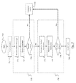
- FIG. 6 is a network environment for implementing an embodiment of the disclosure. Specifically, FIG. 6 shows central management device 610 communicating with switch 620 . Central management device 610 maintains a database of routing tables and node assignments. Switch 620 is shown with exemplary ports P 1 , P 2 and P 3 . In the embodiment of FIG. 6 , ports 1 and 2 are shown has having VMs. P 1 communicates with, hypervisor 1, P 2 communicates with hypervisor 2 and P 3 communicates with hypervisor 3. Each hypervisor can manage one or more VMs. Hypervisor 1 manages VM 1 and VM 2 ; hypervisor 2 manages VM 3 and VM 4 ; hypervisor 3 manages VM 5 . The hypervisor can define a VMware hypervisor. In FIG. 6 the solid lines indicate a link between a switch port and a hypervisor. The dotted lines denote IP connectivity between the nodes.
- a validation trigger can occur if a message is directed at a VM.
- routine validation checks can be implemented periodically.
- a pre-validation step can be used to shorten the validation process. During pre-validation, or in response to an incoming message directed to a VM, the static configuration of the affected (relevant) switch is queried to determine whether the port on which the VM resides is identified at the switch's configuration. If the port is identified in the static configuration, additional validation can be avoided.
- the pre-validation process can be used as a stand alone process or may be combined with one or more of the following validation techniques.
- a so-called Hello protocol is ran on switch ports P 1 , P 2 and P 3 .
- each switch port will send a Hello message in an L2 packet on each of its server-feeing ports.
- the Hello packet contains an identification of the switch (e.g., the Management IP Address) and an identification of the port (e.g., the port number) on which the packet is sent.
- the Hello protocol may be an especially-devised protocol or a conventional protocol such as CDP or LLDP.
- the Hello packets are sent peer-to-peer such that the packets are not forwarded by the switch. This will ensure that the switch port connected to the hypervisor NIC is the source of the Hello packet.
- the associated hypervisor maintains a database of the information in the received hello packet and the port number on which the Hello packet was received.
- Each, hypervisor ( 630 , 640 , 650 ) sends its database to central management device 610 .
- the database on each hypervisor can be queried from Central Management Device 610 .
- central management device 610 will contain information about the switch port to which the hypervisors are connected.
- Switch 626 may comprise a local cache of the database (not shown), or may query a database (not shown) associated with central management device 621 ) on demand.
- Switch 621 may query the database to determine if a particular switch port is connected to a VMware hypervisor.
- a switch port (e.g., P 1 , P 2 , P 3 ) connected which is connected to a VMware hypervisor is assumed to be a trusted port.
- FIG. 7 is a flow-diagram schematically showing an implementation according to one embodiment of the disclosure. Particularly, FIG. 7 shows pre-validation 712 and two independent modes of validation checking: basic validation (interchangeably, verification) 720 and advanced validation 730 .
- the process of FIG. 7 starts at step 710 when a new VM is discovered or as part of a periodically-scheduled validation command.
- Switch 630 ( FIG. 6 ) may perform pre-validation and/or validation-when a VM MAC address is detected on a new port. Switch 630 may also perform trusted port checking whenever a link goes up or down.
- Pre-validation check 710 seeks to efficiently identify authenticity of the newly-discovered VM. Pre-validation starts by querying the static configuration stored on the switch. The static configuration file/table is conventionally stored on the switch and, among others, maintains data directed to ports residing on each switch. If the static configuration identifies the port on which the target VM resides, then the port and the VM are assumed to be trusted and further validation may not be need.
- the network manager may optionally require additional validations through one or both of validation checks 720 and 730 . Once a port or VM is identified as trusted, further validation may not be needed until a communication link is interrupted.
- the Hello packet is sent to the identified port.
- the switch e.g., switch 620
- the switch will query a database 726 (not shown) to determine whether traffic from the newly-seen VM is arriving from a trusted port (e.g., P 1 ). If the basic validation check 720 is successful, traffic is forwarded to the VM as shown in step 728 . If the basic validation check fails, one or more of the user-specified actions will occur.
- the user-specified actions may include: (1) generating a warning syslog; (2) disabling the port; (3) creating an access control list (ACL) to drop traffic from the suspected MAC; or (4) conduct advance validation check 730 .
- the switch will check for VM MAC duplication and VM MAC reuse.
- the Hello packet's attributes are identified. This information is available from the packet itself.
- the expected attributes of the Hello packet are retrieved from the database.
- the switch will query the database and ensures that the VM MAC is unique and the VM UUID will be retrieved from the database (step 734 ) and used for VM MAC validation check.
- the switch will also query the database to determine if traffic from the newly-discovered VM is arriving from a trusted port and whether the following attributes match:
- the MAC Address appearing on the switch port is deemed verified only if all four attributes match exactly. In another embodiment, one or more attribute must match to validate authenticity.
- the attribute matching step is shown as step 736 .
- the validation cheeks of FIG. 7 guard against spoofing, duplicate MAC address and reused MAC address. If the attribution match fails, the VM is invalidated at step 740 ,
Abstract
Description
Claims (12)
Priority Applications (1)
| Application Number | Priority Date | Filing Date | Title |
|---|---|---|---|
| US13/975,310 US9276953B2 (en) | 2011-05-13 | 2013-08-24 | Method and apparatus to detect and block unauthorized MAC address by virtual machine aware network switches |
Applications Claiming Priority (2)
| Application Number | Priority Date | Filing Date | Title |
|---|---|---|---|
| US13/107,397 US20120287931A1 (en) | 2011-05-13 | 2011-05-13 | Techniques for securing a virtualized computing environment using a physical network switch |
| US13/975,310 US9276953B2 (en) | 2011-05-13 | 2013-08-24 | Method and apparatus to detect and block unauthorized MAC address by virtual machine aware network switches |
Related Parent Applications (1)
| Application Number | Title | Priority Date | Filing Date |
|---|---|---|---|
| US13/107,397 Continuation-In-Part US20120287931A1 (en) | 2011-05-13 | 2011-05-13 | Techniques for securing a virtualized computing environment using a physical network switch |
Publications (2)
| Publication Number | Publication Date |
|---|---|
| US20140007232A1 US20140007232A1 (en) | 2014-01-02 |
| US9276953B2 true US9276953B2 (en) | 2016-03-01 |
Family
ID=49779763
Family Applications (1)
| Application Number | Title | Priority Date | Filing Date |
|---|---|---|---|
| US13/975,310 Expired - Fee Related US9276953B2 (en) | 2011-05-13 | 2013-08-24 | Method and apparatus to detect and block unauthorized MAC address by virtual machine aware network switches |
Country Status (1)
| Country | Link |
|---|---|
| US (1) | US9276953B2 (en) |
Cited By (4)
| Publication number | Priority date | Publication date | Assignee | Title |
|---|---|---|---|---|
| US20210297433A1 (en) * | 2019-02-01 | 2021-09-23 | Huawei Technologies Co., Ltd. | Method and apparatus for preventing network attack |
| US11144370B2 (en) * | 2019-01-07 | 2021-10-12 | Realtek Semiconductor Corporation | Communication method for virtual machines, electronic device, and non-transitory computer readable storage medium |
| US11438375B2 (en) | 2020-06-02 | 2022-09-06 | Saudi Arabian Oil Company | Method and system for preventing medium access control (MAC) spoofing attacks in a communication network |
| US20230089819A1 (en) * | 2021-09-22 | 2023-03-23 | Hewlett Packard Enterprise Development Lp | Source port-based identification of client role |
Families Citing this family (12)
| Publication number | Priority date | Publication date | Assignee | Title |
|---|---|---|---|---|
| US9129124B2 (en) * | 2012-04-12 | 2015-09-08 | Hewlett-Packard Development Company, L.P. | Dynamic provisioning of virtual systems |
| US20150207793A1 (en) * | 2012-07-31 | 2015-07-23 | Parvez Syed Mohamed | Feature Enablement or Disablement Based on Discovery Message |
| US20140172947A1 (en) * | 2012-12-17 | 2014-06-19 | Benu Networks, Inc. | Cloud-based virtual local networks |
| US9342669B2 (en) * | 2013-07-11 | 2016-05-17 | Dialogic, Inc. | Systems and methods of licensing and identification of virtual network appliances |
| CN103841186B (en) * | 2014-02-25 | 2018-05-01 | 汉柏科技有限公司 | The group technology and system of a kind of private clound |
| US10915383B2 (en) | 2014-07-31 | 2021-02-09 | Micro Focus Llc | Remote session information based on process identifier |
| CN107113280A (en) * | 2014-12-31 | 2017-08-29 | 华为技术有限公司 | A kind of network control method and virtual switch |
| CN106648835B (en) * | 2016-12-26 | 2020-04-10 | 武汉斗鱼网络科技有限公司 | Method and system for detecting running of Android application program in Android simulator |
| US10397095B2 (en) * | 2017-01-03 | 2019-08-27 | Cisco Technology, Inc. | Detecting and mitigating loops |
| US11068310B2 (en) * | 2019-03-08 | 2021-07-20 | International Business Machines Corporation | Secure storage query and donation |
| US11176054B2 (en) | 2019-03-08 | 2021-11-16 | International Business Machines Corporation | Host virtual address space for secure interface control storage |
| CN111010362B (en) * | 2019-03-20 | 2021-09-21 | 新华三技术有限公司 | Monitoring method and device for abnormal host |
Citations (98)
| Publication number | Priority date | Publication date | Assignee | Title |
|---|---|---|---|---|
| US5394402A (en) | 1993-06-17 | 1995-02-28 | Ascom Timeplex Trading Ag | Hub for segmented virtual local area network with shared media access |
| US5515359A (en) | 1994-08-26 | 1996-05-07 | Mitsubishi Electric Research Laboratories, Inc. | Credit enhanced proportional rate control system |
| US5617421A (en) | 1994-06-17 | 1997-04-01 | Cisco Systems, Inc. | Extended domain computer network using standard links |
| US5633861A (en) | 1994-12-19 | 1997-05-27 | Alcatel Data Networks Inc. | Traffic management and congestion control for packet-based networks |
| US5633859A (en) | 1994-09-16 | 1997-05-27 | The Ohio State University | Method and apparatus for congestion management in computer networks using explicit rate indication |
| US5742604A (en) | 1996-03-28 | 1998-04-21 | Cisco Systems, Inc. | Interswitch link mechanism for connecting high-performance network switches |
| EP0853405A2 (en) | 1997-01-06 | 1998-07-15 | Digital Equipment Corporation | Ethernet network with credit based flow control |
| US5893320A (en) | 1997-05-20 | 1999-04-13 | Demaree; Michael S. | Device for cooking fowl |
| US6147970A (en) | 1997-09-30 | 2000-11-14 | Gte Internetworking Incorporated | Quality of service management for aggregated flows in a network system |
| US6304901B1 (en) | 1996-01-02 | 2001-10-16 | Cisco Technology, Inc. | Multiple VLAN architecture system |
| US6347337B1 (en) | 1999-01-08 | 2002-02-12 | Intel Corporation | Credit based flow control scheme over virtual interface architecture for system area networks |
| US20020191628A1 (en) | 2001-06-12 | 2002-12-19 | Actue Communications Corporation | Apparatus for multicast forwarding in a virtual local area network environment |
| US6567403B1 (en) | 1998-04-30 | 2003-05-20 | Hewlett-Packard Development Company, L.P. | Virtual-chassis switch network topology |
| US20030105881A1 (en) | 2001-12-03 | 2003-06-05 | Symons Julie Anna | Method for detecting and preventing intrusion in a virtually-wired switching fabric |
| US20030185206A1 (en) | 2002-03-29 | 2003-10-02 | Bhaskar Jayakrishnan | Destination device bit map for delivering an information packet through a switch fabric |
| US6646985B1 (en) | 1999-06-03 | 2003-11-11 | Fujitsu Network Communications, Inc. | Congestion control mechanism in a network access device |
| US20040088451A1 (en) | 2002-11-01 | 2004-05-06 | Samsung Electronics Co., Ltd. | Device and method for controlling packet flow |
| US20040243663A1 (en) | 2003-04-08 | 2004-12-02 | Johanson Bradley E. | Event heap: a coordination infrastructure for dynamic heterogeneous application interactions in ubiquitous computing environments |
| US20040255288A1 (en) | 2003-05-27 | 2004-12-16 | Shinya Hashimoto | Software update processor, system, method, program for the same, and recording medium with the program recorded therein |
| US6839768B2 (en) | 1997-06-13 | 2005-01-04 | At&T Corp. | Startup management system and method for rate-based flow and congestion control within a network |
| US20050047334A1 (en) | 2001-06-13 | 2005-03-03 | Paul Harry V. | Fibre channel switch |
| US6901452B1 (en) | 2000-03-02 | 2005-05-31 | Alcatel | Selectable prioritization for data communication switch |
| US20060029072A1 (en) | 2003-10-14 | 2006-02-09 | Raptor Networks Technology, Inc. | Switching system for virtual LANs |
| US7035220B1 (en) | 2001-10-22 | 2006-04-25 | Intel Corporation | Technique for providing end-to-end congestion control with no feedback from a lossless network |
| JP2006148255A (en) | 2004-11-16 | 2006-06-08 | Hitachi Ltd | Apparatus and method for specifying connected position of illegitimate apparatus |
| US20060251067A1 (en) | 2004-10-22 | 2006-11-09 | Cisco Technology, Inc., A Corporation Of California | Fibre channel over ethernet |
| CN1897567A (en) | 2005-07-15 | 2007-01-17 | 华为技术有限公司 | Method for improving transmission reliability in virtual exchange system |
| JP2007180796A (en) | 2005-12-27 | 2007-07-12 | Fujitsu Ltd | Differential amplifier circuit |
| US7263060B1 (en) | 2001-06-28 | 2007-08-28 | Network Appliance, Inc. | Multiple switch protected architecture |
| CN101030959A (en) | 2006-02-27 | 2007-09-05 | 中兴通讯股份有限公司 | Telecommunication for determining realtime Ethernet transmission |
| US20070263640A1 (en) | 2006-05-10 | 2007-11-15 | Finn Norman W | Technique for efficiently managing bandwidth for multipoint-to-multipoint services in a provider network |
| CN101087238A (en) | 2003-10-21 | 2007-12-12 | 华为技术有限公司 | Dynamic bandwidth allocation device and method of passive optical network |
| US7386876B2 (en) | 2000-07-06 | 2008-06-10 | Samsung Electronics Co., Ltd. | MAC address-based communication restricting method |
| US20080205377A1 (en) | 2007-02-22 | 2008-08-28 | Blade Network Technologies, Inc. | System and methods for providing server virtualization assistance |
| US20080228897A1 (en) | 2007-03-12 | 2008-09-18 | Ko Michael A | Layering serial attached small computer system interface (sas) over ethernet |
| US20080225712A1 (en) | 2007-03-13 | 2008-09-18 | Lange Andrew S | Policy enforcement points |
| EP2009862A1 (en) | 2007-06-29 | 2008-12-31 | Nokia Siemens Networks Oy | Method for protection a network through port blocking |
| US20090129385A1 (en) | 2004-09-17 | 2009-05-21 | Hewlett-Packard Development Company, L. P. | Virtual network interface |
| US7561517B2 (en) | 2001-11-02 | 2009-07-14 | Internap Network Services Corporation | Passive route control of data networks |
| US20090185571A1 (en) | 2008-01-23 | 2009-07-23 | Francois Edouard Tallet | Translating mst instances between ports of a bridge in a computer network |
| US20090213869A1 (en) | 2008-02-26 | 2009-08-27 | Saravanakumar Rajendran | Blade switch |
| US7593320B1 (en) | 2004-04-30 | 2009-09-22 | Marvell International, Ltd. | Failover scheme for stackable network switches |
| US20090252038A1 (en) | 2004-10-22 | 2009-10-08 | Cisco Technology, Inc. | Fibre channel over ethernet |
| US7668966B2 (en) | 2001-11-02 | 2010-02-23 | Internap Network Services Corporation | Data network controller |
| US20100054129A1 (en) | 2008-08-27 | 2010-03-04 | Cisco Technology, Inc. | Virtual switch quality of service for virtual machines |
| US20100054260A1 (en) | 2008-08-28 | 2010-03-04 | Blade Network Technologies, Inc. | Method and Apparatus to Switch Packets between Virtual Ports |
| US20100158024A1 (en) | 2008-12-23 | 2010-06-24 | Ali Sajassi | Optimized forwarding for provider backbone bridges with both i&b components (ib-pbb) |
| US20100183011A1 (en) | 2007-06-11 | 2010-07-22 | Blade Network Technologies, Inc. | Sequential frame forwarding |
| CN101809943A (en) | 2007-09-24 | 2010-08-18 | 英特尔公司 | Method and system for virtual port communications |
| WO2010096155A1 (en) | 2009-02-23 | 2010-08-26 | Cisco Technology, Inc. | Distributed data center access switch |
| US20100223397A1 (en) | 2009-02-27 | 2010-09-02 | Uri Elzur | Method and system for virtual machine networking |
| US20100226368A1 (en) | 2009-03-06 | 2010-09-09 | Futurewei Technologies, Inc. | Transport Multiplexer - Mechanisms to Force Ethernet Traffic From One Domain to Be Switched in a Different (External) Domain |
| US20100246388A1 (en) | 2009-03-26 | 2010-09-30 | Brocade Communications Systems, Inc. | Redundant host connection in a routed network |
| US20100265824A1 (en) | 2007-11-09 | 2010-10-21 | Blade Network Technologies, Inc | Session-less Load Balancing of Client Traffic Across Servers in a Server Group |
| US7830793B2 (en) | 2004-10-22 | 2010-11-09 | Cisco Technology, Inc. | Network device architecture for consolidating input/output and reducing latency |
| US7839777B2 (en) | 2007-09-27 | 2010-11-23 | International Business Machines Corporation | Method, system, and apparatus for accelerating resolution of network congestion |
| US20100303075A1 (en) | 2009-05-29 | 2010-12-02 | Sun Microsystems, Inc. | Managing traffic on virtualized lanes between a network switch and a virtual machine |
| US7848226B2 (en) | 2007-03-28 | 2010-12-07 | Fujitsu Limited | Communication system, switch |
| US20110007746A1 (en) | 2009-07-10 | 2011-01-13 | Jayaram Mudigonda | Establishing Network Quality of Service for a Virtual Machine |
| US20110019678A1 (en) | 2009-07-24 | 2011-01-27 | Juniper Networks, Inc. | Routing frames in a shortest path computer network for a multi-homed legacy bridge node |
| US20110026403A1 (en) | 2007-11-09 | 2011-02-03 | Blade Network Technologies, Inc | Traffic management of client traffic at ingress location of a data center |
| US20110026527A1 (en) | 2007-06-11 | 2011-02-03 | Blade Network Technologies, Inc. | Tag-based interface between a switching device and servers for use in frame processing and forwarding |
| US20110035494A1 (en) | 2008-04-15 | 2011-02-10 | Blade Network Technologies | Network virtualization for a virtualized server data center environment |
| US20110032944A1 (en) | 2009-08-06 | 2011-02-10 | Uri Elzur | Method and System for Switching in a Virtualized Platform |
| CN101986666A (en) | 2010-11-05 | 2011-03-16 | 清华大学 | Network data transmission method based on virtual network interface and reverse address resolution |
| US7912003B2 (en) | 2007-06-27 | 2011-03-22 | Microsoft Corporation | Multipath forwarding algorithms using network coding |
| US20110103389A1 (en) | 2009-11-03 | 2011-05-05 | Blade Network Technologies, Inc. | Method and apparatus for switching traffic between virtual machines |
| US20110134793A1 (en) | 2009-12-03 | 2011-06-09 | Christian Elsen | Preventing loops on network topologies built with virtual switches and vms |
| US7974223B2 (en) | 2004-11-19 | 2011-07-05 | Corrigent Systems Ltd. | Virtual private LAN service over ring networks |
| US20110238820A1 (en) | 2010-03-23 | 2011-09-29 | Fujitsu Limited | Computer, communication device, and communication control system |
| US20110235523A1 (en) | 2010-03-24 | 2011-09-29 | Brocade Communications Systems, Inc. | Method and system for extending routing domain to non-routing end stations |
| US20110274110A1 (en) | 2010-05-07 | 2011-11-10 | Vishnu Mmmadi | Method for preventing mac spoofs in a distributed virtual switch |
| US20110280572A1 (en) | 2010-05-11 | 2011-11-17 | Brocade Communications Systems, Inc. | Converged network extension |
| US20110299536A1 (en) | 2010-06-08 | 2011-12-08 | Brocade Communications Systems, Inc. | Method and system for link aggregation across multiple switches |
| US20110299532A1 (en) | 2010-06-08 | 2011-12-08 | Brocade Communications Systems, Inc. | Remote port mirroring |
| US20110299409A1 (en) | 2010-06-02 | 2011-12-08 | Brocade Communications Systems, Inc. | Reachability detection in trill networks |
| US20110299406A1 (en) | 2010-06-02 | 2011-12-08 | Brocade Communications Systems, Inc. | Path detection in trill networks |
| US20120014387A1 (en) | 2010-05-28 | 2012-01-19 | Futurewei Technologies, Inc. | Virtual Layer 2 and Mechanism to Make it Scalable |
| US20120014261A1 (en) | 2010-07-14 | 2012-01-19 | Cisco Technology, Inc. | Monitoring A Flow Set To Detect Faults |
| US8139358B2 (en) | 2007-09-25 | 2012-03-20 | International Business Machines Corporation | Apparatus for externally changing the direction of air flowing through electronic equipment |
| JP2012080217A (en) | 2010-09-30 | 2012-04-19 | Nec Corp | Terminal detection device, server device, terminal detection method, and program |
| US8194534B2 (en) | 2005-02-28 | 2012-06-05 | International Business Machines Corporation | Blade server system with at least one rack-switch having multiple switches interconnected and configured for management and operation as a single virtual switch |
| US20120177045A1 (en) | 2011-01-07 | 2012-07-12 | Berman Stuart B | Methods, systems and apparatus for the interconnection of fibre channel over ethernet devices using a trill network |
| US8265075B2 (en) | 2009-03-16 | 2012-09-11 | International Business Machines Corporation | Method and apparatus for managing, configuring, and controlling an I/O virtualization device through a network switch |
| US20120228780A1 (en) | 2011-03-08 | 2012-09-13 | Ji Hwang Kim | Semiconductor device and method of manufacturing the same |
| US8271680B2 (en) | 1998-12-24 | 2012-09-18 | Ericsson Ab | Domain isolation through virtual network machines |
| US20120243544A1 (en) | 2011-03-21 | 2012-09-27 | Avaya Inc. | Usage of masked bmac addresses in a provider backbone bridged (pbb) network |
| US20120243539A1 (en) | 2011-03-21 | 2012-09-27 | Avaya Inc. | Usage of masked ethernet addresses between transparent interconnect of lots of links (trill) routing bridges |
| US20120291028A1 (en) | 2011-05-13 | 2012-11-15 | International Business Machines Corporation | Securing a virtualized computing environment using a physical network switch |
| US20120287787A1 (en) | 2011-05-14 | 2012-11-15 | International Business Machines Corporation | Priority based flow control in a distributed fabric protocol (dfp) switching network architecture |
| US20120287939A1 (en) | 2011-05-14 | 2012-11-15 | International Business Machines Corporation | Distributed fabric protocol (dfp) switching network architecture |
| US8325598B2 (en) | 2009-05-20 | 2012-12-04 | Verizon Patent And Licensing Inc. | Automatic protection switching of virtual connections |
| US20120320749A1 (en) | 2011-05-14 | 2012-12-20 | International Business Machines Corporation | Data traffic handling in a distributed fabric protocol (dfp) switching network architecture |
| US8345697B2 (en) | 2010-08-17 | 2013-01-01 | Dell Products, Lp | System and method for carrying path information |
| US20130051235A1 (en) | 2011-08-29 | 2013-02-28 | Brocade Communications Systems, Inc. | End-to-end lossless ethernet in ethernet fabric |
| US20130064068A1 (en) | 2011-09-12 | 2013-03-14 | International Business Machines Corporation | High availability distributed fabric protocol (dfp) switching network architecture |
| US8406128B1 (en) | 2010-06-29 | 2013-03-26 | Amazon Technologies, Inc. | Efficient highly connected data centers |
| US8498299B2 (en) | 2010-08-19 | 2013-07-30 | Juniper Networks, Inc. | Flooding-based routing protocol having average-rate and burst-rate control |
-
2013
- 2013-08-24 US US13/975,310 patent/US9276953B2/en not_active Expired - Fee Related
Patent Citations (103)
| Publication number | Priority date | Publication date | Assignee | Title |
|---|---|---|---|---|
| US5394402A (en) | 1993-06-17 | 1995-02-28 | Ascom Timeplex Trading Ag | Hub for segmented virtual local area network with shared media access |
| US5617421A (en) | 1994-06-17 | 1997-04-01 | Cisco Systems, Inc. | Extended domain computer network using standard links |
| US5515359A (en) | 1994-08-26 | 1996-05-07 | Mitsubishi Electric Research Laboratories, Inc. | Credit enhanced proportional rate control system |
| US5633859A (en) | 1994-09-16 | 1997-05-27 | The Ohio State University | Method and apparatus for congestion management in computer networks using explicit rate indication |
| US5633861A (en) | 1994-12-19 | 1997-05-27 | Alcatel Data Networks Inc. | Traffic management and congestion control for packet-based networks |
| US6304901B1 (en) | 1996-01-02 | 2001-10-16 | Cisco Technology, Inc. | Multiple VLAN architecture system |
| US5742604A (en) | 1996-03-28 | 1998-04-21 | Cisco Systems, Inc. | Interswitch link mechanism for connecting high-performance network switches |
| EP0853405A2 (en) | 1997-01-06 | 1998-07-15 | Digital Equipment Corporation | Ethernet network with credit based flow control |
| US5893320A (en) | 1997-05-20 | 1999-04-13 | Demaree; Michael S. | Device for cooking fowl |
| US6839768B2 (en) | 1997-06-13 | 2005-01-04 | At&T Corp. | Startup management system and method for rate-based flow and congestion control within a network |
| US6147970A (en) | 1997-09-30 | 2000-11-14 | Gte Internetworking Incorporated | Quality of service management for aggregated flows in a network system |
| US6567403B1 (en) | 1998-04-30 | 2003-05-20 | Hewlett-Packard Development Company, L.P. | Virtual-chassis switch network topology |
| US8271680B2 (en) | 1998-12-24 | 2012-09-18 | Ericsson Ab | Domain isolation through virtual network machines |
| US6347337B1 (en) | 1999-01-08 | 2002-02-12 | Intel Corporation | Credit based flow control scheme over virtual interface architecture for system area networks |
| US6646985B1 (en) | 1999-06-03 | 2003-11-11 | Fujitsu Network Communications, Inc. | Congestion control mechanism in a network access device |
| US6901452B1 (en) | 2000-03-02 | 2005-05-31 | Alcatel | Selectable prioritization for data communication switch |
| US7386876B2 (en) | 2000-07-06 | 2008-06-10 | Samsung Electronics Co., Ltd. | MAC address-based communication restricting method |
| US20020191628A1 (en) | 2001-06-12 | 2002-12-19 | Actue Communications Corporation | Apparatus for multicast forwarding in a virtual local area network environment |
| US20050047334A1 (en) | 2001-06-13 | 2005-03-03 | Paul Harry V. | Fibre channel switch |
| US7263060B1 (en) | 2001-06-28 | 2007-08-28 | Network Appliance, Inc. | Multiple switch protected architecture |
| US7035220B1 (en) | 2001-10-22 | 2006-04-25 | Intel Corporation | Technique for providing end-to-end congestion control with no feedback from a lossless network |
| US7668966B2 (en) | 2001-11-02 | 2010-02-23 | Internap Network Services Corporation | Data network controller |
| US7561517B2 (en) | 2001-11-02 | 2009-07-14 | Internap Network Services Corporation | Passive route control of data networks |
| US20030105881A1 (en) | 2001-12-03 | 2003-06-05 | Symons Julie Anna | Method for detecting and preventing intrusion in a virtually-wired switching fabric |
| US20030185206A1 (en) | 2002-03-29 | 2003-10-02 | Bhaskar Jayakrishnan | Destination device bit map for delivering an information packet through a switch fabric |
| US20040088451A1 (en) | 2002-11-01 | 2004-05-06 | Samsung Electronics Co., Ltd. | Device and method for controlling packet flow |
| US20040243663A1 (en) | 2003-04-08 | 2004-12-02 | Johanson Bradley E. | Event heap: a coordination infrastructure for dynamic heterogeneous application interactions in ubiquitous computing environments |
| US20040255288A1 (en) | 2003-05-27 | 2004-12-16 | Shinya Hashimoto | Software update processor, system, method, program for the same, and recording medium with the program recorded therein |
| US20060029072A1 (en) | 2003-10-14 | 2006-02-09 | Raptor Networks Technology, Inc. | Switching system for virtual LANs |
| CN101087238A (en) | 2003-10-21 | 2007-12-12 | 华为技术有限公司 | Dynamic bandwidth allocation device and method of passive optical network |
| US7593320B1 (en) | 2004-04-30 | 2009-09-22 | Marvell International, Ltd. | Failover scheme for stackable network switches |
| US20090129385A1 (en) | 2004-09-17 | 2009-05-21 | Hewlett-Packard Development Company, L. P. | Virtual network interface |
| US8213429B2 (en) | 2004-09-17 | 2012-07-03 | Hewlett-Packard Development Company, L.P. | Virtual network interface |
| US20090252038A1 (en) | 2004-10-22 | 2009-10-08 | Cisco Technology, Inc. | Fibre channel over ethernet |
| US7830793B2 (en) | 2004-10-22 | 2010-11-09 | Cisco Technology, Inc. | Network device architecture for consolidating input/output and reducing latency |
| US20060251067A1 (en) | 2004-10-22 | 2006-11-09 | Cisco Technology, Inc., A Corporation Of California | Fibre channel over ethernet |
| JP2006148255A (en) | 2004-11-16 | 2006-06-08 | Hitachi Ltd | Apparatus and method for specifying connected position of illegitimate apparatus |
| US7974223B2 (en) | 2004-11-19 | 2011-07-05 | Corrigent Systems Ltd. | Virtual private LAN service over ring networks |
| US8194534B2 (en) | 2005-02-28 | 2012-06-05 | International Business Machines Corporation | Blade server system with at least one rack-switch having multiple switches interconnected and configured for management and operation as a single virtual switch |
| CN1897567A (en) | 2005-07-15 | 2007-01-17 | 华为技术有限公司 | Method for improving transmission reliability in virtual exchange system |
| JP2007180796A (en) | 2005-12-27 | 2007-07-12 | Fujitsu Ltd | Differential amplifier circuit |
| CN101030959A (en) | 2006-02-27 | 2007-09-05 | 中兴通讯股份有限公司 | Telecommunication for determining realtime Ethernet transmission |
| US20070263640A1 (en) | 2006-05-10 | 2007-11-15 | Finn Norman W | Technique for efficiently managing bandwidth for multipoint-to-multipoint services in a provider network |
| US20080205377A1 (en) | 2007-02-22 | 2008-08-28 | Blade Network Technologies, Inc. | System and methods for providing server virtualization assistance |
| US20080228897A1 (en) | 2007-03-12 | 2008-09-18 | Ko Michael A | Layering serial attached small computer system interface (sas) over ethernet |
| US20080225712A1 (en) | 2007-03-13 | 2008-09-18 | Lange Andrew S | Policy enforcement points |
| US7848226B2 (en) | 2007-03-28 | 2010-12-07 | Fujitsu Limited | Communication system, switch |
| US20100183011A1 (en) | 2007-06-11 | 2010-07-22 | Blade Network Technologies, Inc. | Sequential frame forwarding |
| US20110026527A1 (en) | 2007-06-11 | 2011-02-03 | Blade Network Technologies, Inc. | Tag-based interface between a switching device and servers for use in frame processing and forwarding |
| US7912003B2 (en) | 2007-06-27 | 2011-03-22 | Microsoft Corporation | Multipath forwarding algorithms using network coding |
| EP2009862A1 (en) | 2007-06-29 | 2008-12-31 | Nokia Siemens Networks Oy | Method for protection a network through port blocking |
| CN101809943A (en) | 2007-09-24 | 2010-08-18 | 英特尔公司 | Method and system for virtual port communications |
| US8139358B2 (en) | 2007-09-25 | 2012-03-20 | International Business Machines Corporation | Apparatus for externally changing the direction of air flowing through electronic equipment |
| US7839777B2 (en) | 2007-09-27 | 2010-11-23 | International Business Machines Corporation | Method, system, and apparatus for accelerating resolution of network congestion |
| US20100265824A1 (en) | 2007-11-09 | 2010-10-21 | Blade Network Technologies, Inc | Session-less Load Balancing of Client Traffic Across Servers in a Server Group |
| US20110026403A1 (en) | 2007-11-09 | 2011-02-03 | Blade Network Technologies, Inc | Traffic management of client traffic at ingress location of a data center |
| US20090185571A1 (en) | 2008-01-23 | 2009-07-23 | Francois Edouard Tallet | Translating mst instances between ports of a bridge in a computer network |
| US20090213869A1 (en) | 2008-02-26 | 2009-08-27 | Saravanakumar Rajendran | Blade switch |
| US20110035494A1 (en) | 2008-04-15 | 2011-02-10 | Blade Network Technologies | Network virtualization for a virtualized server data center environment |
| US20100054129A1 (en) | 2008-08-27 | 2010-03-04 | Cisco Technology, Inc. | Virtual switch quality of service for virtual machines |
| US20100054260A1 (en) | 2008-08-28 | 2010-03-04 | Blade Network Technologies, Inc. | Method and Apparatus to Switch Packets between Virtual Ports |
| US20100158024A1 (en) | 2008-12-23 | 2010-06-24 | Ali Sajassi | Optimized forwarding for provider backbone bridges with both i&b components (ib-pbb) |
| WO2010096155A1 (en) | 2009-02-23 | 2010-08-26 | Cisco Technology, Inc. | Distributed data center access switch |
| US20100223397A1 (en) | 2009-02-27 | 2010-09-02 | Uri Elzur | Method and system for virtual machine networking |
| US20100226368A1 (en) | 2009-03-06 | 2010-09-09 | Futurewei Technologies, Inc. | Transport Multiplexer - Mechanisms to Force Ethernet Traffic From One Domain to Be Switched in a Different (External) Domain |
| US8265075B2 (en) | 2009-03-16 | 2012-09-11 | International Business Machines Corporation | Method and apparatus for managing, configuring, and controlling an I/O virtualization device through a network switch |
| US20100246388A1 (en) | 2009-03-26 | 2010-09-30 | Brocade Communications Systems, Inc. | Redundant host connection in a routed network |
| US8325598B2 (en) | 2009-05-20 | 2012-12-04 | Verizon Patent And Licensing Inc. | Automatic protection switching of virtual connections |
| US20100303075A1 (en) | 2009-05-29 | 2010-12-02 | Sun Microsystems, Inc. | Managing traffic on virtualized lanes between a network switch and a virtual machine |
| US20110007746A1 (en) | 2009-07-10 | 2011-01-13 | Jayaram Mudigonda | Establishing Network Quality of Service for a Virtual Machine |
| US20110019678A1 (en) | 2009-07-24 | 2011-01-27 | Juniper Networks, Inc. | Routing frames in a shortest path computer network for a multi-homed legacy bridge node |
| US20110032944A1 (en) | 2009-08-06 | 2011-02-10 | Uri Elzur | Method and System for Switching in a Virtualized Platform |
| US20110103389A1 (en) | 2009-11-03 | 2011-05-05 | Blade Network Technologies, Inc. | Method and apparatus for switching traffic between virtual machines |
| US20110134793A1 (en) | 2009-12-03 | 2011-06-09 | Christian Elsen | Preventing loops on network topologies built with virtual switches and vms |
| US20110238820A1 (en) | 2010-03-23 | 2011-09-29 | Fujitsu Limited | Computer, communication device, and communication control system |
| US20110235523A1 (en) | 2010-03-24 | 2011-09-29 | Brocade Communications Systems, Inc. | Method and system for extending routing domain to non-routing end stations |
| US20110274110A1 (en) | 2010-05-07 | 2011-11-10 | Vishnu Mmmadi | Method for preventing mac spoofs in a distributed virtual switch |
| US20110280572A1 (en) | 2010-05-11 | 2011-11-17 | Brocade Communications Systems, Inc. | Converged network extension |
| US20120014387A1 (en) | 2010-05-28 | 2012-01-19 | Futurewei Technologies, Inc. | Virtual Layer 2 and Mechanism to Make it Scalable |
| US20110299406A1 (en) | 2010-06-02 | 2011-12-08 | Brocade Communications Systems, Inc. | Path detection in trill networks |
| US20110299409A1 (en) | 2010-06-02 | 2011-12-08 | Brocade Communications Systems, Inc. | Reachability detection in trill networks |
| US20110299536A1 (en) | 2010-06-08 | 2011-12-08 | Brocade Communications Systems, Inc. | Method and system for link aggregation across multiple switches |
| US20110299532A1 (en) | 2010-06-08 | 2011-12-08 | Brocade Communications Systems, Inc. | Remote port mirroring |
| US8406128B1 (en) | 2010-06-29 | 2013-03-26 | Amazon Technologies, Inc. | Efficient highly connected data centers |
| US20120014261A1 (en) | 2010-07-14 | 2012-01-19 | Cisco Technology, Inc. | Monitoring A Flow Set To Detect Faults |
| US8345697B2 (en) | 2010-08-17 | 2013-01-01 | Dell Products, Lp | System and method for carrying path information |
| US8498299B2 (en) | 2010-08-19 | 2013-07-30 | Juniper Networks, Inc. | Flooding-based routing protocol having average-rate and burst-rate control |
| JP2012080217A (en) | 2010-09-30 | 2012-04-19 | Nec Corp | Terminal detection device, server device, terminal detection method, and program |
| CN101986666A (en) | 2010-11-05 | 2011-03-16 | 清华大学 | Network data transmission method based on virtual network interface and reverse address resolution |
| US20120177045A1 (en) | 2011-01-07 | 2012-07-12 | Berman Stuart B | Methods, systems and apparatus for the interconnection of fibre channel over ethernet devices using a trill network |
| US20120228780A1 (en) | 2011-03-08 | 2012-09-13 | Ji Hwang Kim | Semiconductor device and method of manufacturing the same |
| US20120243539A1 (en) | 2011-03-21 | 2012-09-27 | Avaya Inc. | Usage of masked ethernet addresses between transparent interconnect of lots of links (trill) routing bridges |
| US20120243544A1 (en) | 2011-03-21 | 2012-09-27 | Avaya Inc. | Usage of masked bmac addresses in a provider backbone bridged (pbb) network |
| US20120287931A1 (en) | 2011-05-13 | 2012-11-15 | International Business Machines Corporation | Techniques for securing a virtualized computing environment using a physical network switch |
| US20120291028A1 (en) | 2011-05-13 | 2012-11-15 | International Business Machines Corporation | Securing a virtualized computing environment using a physical network switch |
| US20120287786A1 (en) | 2011-05-14 | 2012-11-15 | International Business Machines Corporation | Priority based flow control in a distributed fabric protocol (dfp) switching network architecture |
| US20120320749A1 (en) | 2011-05-14 | 2012-12-20 | International Business Machines Corporation | Data traffic handling in a distributed fabric protocol (dfp) switching network architecture |
| US20130022050A1 (en) | 2011-05-14 | 2013-01-24 | International Business Machines Corporation | Distributed fabric protocol (dfp) switching network architecture |
| US20120287939A1 (en) | 2011-05-14 | 2012-11-15 | International Business Machines Corporation | Distributed fabric protocol (dfp) switching network architecture |
| US20120287787A1 (en) | 2011-05-14 | 2012-11-15 | International Business Machines Corporation | Priority based flow control in a distributed fabric protocol (dfp) switching network architecture |
| US20130051235A1 (en) | 2011-08-29 | 2013-02-28 | Brocade Communications Systems, Inc. | End-to-end lossless ethernet in ethernet fabric |
| US20130064068A1 (en) | 2011-09-12 | 2013-03-14 | International Business Machines Corporation | High availability distributed fabric protocol (dfp) switching network architecture |
| US20130064067A1 (en) | 2011-09-12 | 2013-03-14 | International Business Machines Corporation | High availability distributed fabric protocol (dfp) switching network architecture |
Non-Patent Citations (77)
| Title |
|---|
| Bates, et al., Deactivating Co-Residency With Active Traffic Analysis Techniques, CCSW, Oct. 19, 2012. |
| Brocade, "BCEFE in a Nutshell First Edition", Global Education Services Rev. 0111, pp. 1-70, Copyright 2011, Brocade Communications Systems, Inc. |
| Cisco Systems Inc., "Cisco FabricPath Overview", pp. 1-20, Copyright 2009. |
| D.E. Eastlake, "Rbridges and the IETF TRILL Protocol", pp. 1-39, TRILL Protocol, Dec. 2009. |
| De-Leon, "Flow Control for Gigabit", Digital Equipment Corporation (Digital), IEEE 802.3z Task Force, Jul. 9, 1996, pp. 1-31. |
| Dobre, Multi-Architecture Operating Systems, Oct. 4, 2004, 82 pages. |
| Guha et al., ShutUp: End-to-End Containment of Unwanted Traffic, pp. 1-14, (2008). |
| Hunter et al., BladeCenter Networking, IBM Journal of Research and Development, vol. 49, No. 6, pp. 905-919, Nov. 2005. |
| Int'l Searching Authority; Int. Appln. PCT/182012/051803; Int'l Search Report dated Sep. 13, 2012, 8 pages. |
| Jo et al., "Internet Traffic Load Balancing using Dynamic Hashing with Flow Volume", Conference Title: Internet Performance and Control of Network Systems III, Boston, MA pp. 1-12, Jul. 30, 2002. |
| Kandula, et al., "Dynamic Load Balancing Without Packet Reordering", ACM SIGCOMM Computer Communication Review, vol. 37, No. 2, pp. 53-62, Apr. 2007. |
| Kinds, et al., "Advanced Network Monitoring Brings Life to the Awareness Plane", IBM Research Spyros Denazis, Univ. of Patras Benoit Claise, Cisco Systems, IEEE Communications Magazine, pp. 1-7, Oct. 2008. |
| Leu, Dar-Ren, "dLAG-DMLT over TRILL", Blade Network Technologies, pp. 1-20, Copyright 2009. |
| Manral, et al., "Rbridges: Bidirectional Forwarding Detection (BFD) support for TRILL draft-manral-trill-bfd-encaps-01", pp. 1-10, TRILL Working Group INTERNET-DRAFT, Mar. 13, 2011. |
| Martin, et al., "Accuracy and Dynamics of Multi-Stage Load Balancing for Multipath Internet Routing", Institute of Computer Science, Univ. of Wurzburg Am Hubland, Germany, IEEE Int'l Conference on Communications (ICC) Glasgow, UK, pp. 1-8, Jun. 2007. |
| Papadopoulos et al.,"NPACI Rocks: Tools and Techniques for Easily Deploying Manageable Linux Clusters", The San Diego Supercomputer Center, University of California San Diego, La Jolla, CA 92093-0505-Issue Date: 2001, Date of Current Version: Aug. 7, 2002, 20 pages. |
| Perla, "Profiling User Activities on Guest OSes in a Virtual Machine Environment." (2008), 94 pages. |
| Perlman, et al., "Rbridges: Base Protocol Specification", pp. 1-117, TRILL Working Group INTERNET-DRAFT, Mar. 3, 2010. |
| Pettit et al., Virtual Switching in an Era of Advanced Edges, pp. 1-7, Nicira Networks, Palo Alto, California. Version date Jul. 2010. |
| Pfaff et al., Extending Networking into the Virtualization Layer, pp. 1-6, Oct. 2009, Proceedings of the 8th ACM Workshop on Hot Topics in Networks (HotNets-VIII), New York City, New York,. |
| Posted by Mike Fratto, "Cisco's FabricPath and IETF TRILL: Cisco Can't Have Standards Both Ways", Dec. 17, 2010; http://www.networkcomputing.com/data-networking-management/229500205, 2 pages. |
| Recio et al., Automated Ethernet Virtual Bridging, pp. 1-11, IBM 2009. |
| Rouiller, Virtual LAN Security: weaknesses and countermeasures, pp. 1-49, GIAC Security Essentials Practical Assignment Version 1.4b. |
| Ruth et al., Virtual Distributed Environments in a Shared Infrastructure, pp. 63-69, IEEE Computer Society, May 2005. |
| Schlansker, et al., "High-Performance Ethernet-Based Communications for Future Multi-Core Processors", Proceedings of the 2007 ACM/IEEE conference on Supercomputing, Nov. 10-16, 2007, 12 pages. |
| Schueler et al., "TCP-Splitter: A TCP/IP Flow Monitor in Reconfigurable Hardware", Appl. Res. Lab., Washington Univ. pp. 54-59, Feb. 19, 2003. |
| Sherwood et al., FlowVisor: A Network Virtualization Layer, pp. 1-14, Oct. 14, 2009, Deutsche Telekom Inc. R&D Lab, Stanford University, Nicira Networks. |
| Shi et al., Architectural Support for High Speed Protection of Memory Integrity and Confidentiality in Multiprocessor Systems, pp. 1-12, Proceedings of the 13th International Conference on Parallel Architecture and Compilation Techniques (2004). |
| Skyrme et al., Exploring Lua for Concurrent Programming, Journal of Universal Computer Science, vol. 14, No. 21 (2008), submitted: Apr. 16, 2008, accepted: Jun. 5, 2008, appeared: Dec. 1, 2008, 12 pages. |
| Soule, et al., "Traffic Matrices: Balancing Measurements, Interference and Modeling", vol. 33, Issue: 1, Publisher: ACM, pp. 362-373, Year 2005. |
| Sproull et al., "Control and Configuration Software for a Reconfigurable Networking Hardware Platform", Applied Research Laboratory, Washington University, Saint Louis, MO 63130; Issue Date: 2002, Date of Current Version: Jan. 6, 2003, 10 pages. |
| Tolmie, "HIPPI-6400-Designing for speed", 12th Annual Int'l Symposium on High Performance Computing Systems and Applications (HPCSt98), May 20-22, 1998, 25 pages. |
| U.S. Appl. No. 13/107,397, Final Office Action Dated May 29, 2013, 10 pages. |
| U.S. Appl. No. 13/107,397, Final Office Action Dated May 29, 2013, 11 pages. |
| U.S. Appl. No. 13/107,397, Non-Final Office Action Dated Jan. 4, 2013, 16 pages. |
| U.S. Appl. No. 13/107,397, Non-Final Office Action Dated Jan. 4, 2013, 9 pages. |
| U.S. Appl. No. 13/107,433, Final Office Action Dated Jul. 10, 2013, 18 pages. |
| U.S. Appl. No. 13/107,433, Non-Final Office Action Dated Jan. 28, 2013, 23 pages. |
| U.S. Appl. No. 13/107,554, Final Office Action Dated Jul. 3, 2013, 9 pages. |
| U.S. Appl. No. 13/107,554, Non-Final Office Action Dated Jan. 8, 2013, 19 pages. |
| U.S. Appl. No. 13/107,893, Non-Final Office Action Dated Apr. 1, 2013, 33 pages. |
| U.S. Appl. No. 13/107,893, Notice of Allowance Dated Jul. 10, 2013, 21 pages. |
| U.S. Appl. No. 13/107,894, Non-Final Office Action Dated Jun. 20, 2013, 29 pages. |
| U.S. Appl. No. 13/107,896, Non-Final Office Action Dated Mar. 7, 2013, 17 pages. |
| U.S. Appl. No. 13/107,896, Notice of Allowance Dated Jul. 29, 2013, 18 pages. |
| U.S. Appl. No. 13/107,903, Final Office Action Dated Jul. 19, 2013, 21 pages. |
| U.S. Appl. No. 13/107,903, Non-Final Office Action Dated Feb. 22, 2013, 25 pages. |
| U.S. Appl. No. 13/107,903, Notice of Allowance Dated Sep. 11, 2013, 30 pages. |
| U.S. Appl. No. 13/107,985, Non-Final Office Action Dated Feb. 28, 2013, 18 pages. |
| U.S. Appl. No. 13/107,985, Notice of Allowance Dated Jul. 18, 2013, 14 pages. |
| U.S. Appl. No. 13/229,867, Non-Final Office Action Dated May 24, 2013, 30 pages. |
| U.S. Appl. No. 13/229,891, Non-Final Office Action Dated May 9, 2013, 17 pages. |
| U.S. Appl. No. 13/267,459, Non-Final Office Action Dated May 2, 2013, 17 pages. |
| U.S. Appl. No. 13/267,578, Non-Final Office Action Dated Apr. 5, 2013, 18 pages. |
| U.S. Appl. No. 13/267,578, Non-Final Office Action Dated Aug. 6, 2013, 19 pages. |
| U.S. Appl. No. 13/314,455, Final Office Action Dated Aug. 30, 2013, 19 pages. |
| U.S. Appl. No. 13/314,455, Non-Final Office Action Dated Apr. 24, 2013, 19 pages. |
| U.S. Appl. No. 13/466,754, Non-Final Office Action Dated Sep. 25, 2013, 10 pages. |
| U.S. Appl. No. 13/466,754, Non-Final Office Action Dated Sep. 25, 2013, 15 pages. |
| U.S. Appl. No. 13/466,790, Final Office Action Dated Jul. 12, 2013, 19 pages. |
| U.S. Appl. No. 13/466,790, Non-Final Office Action Dated Feb. 15, 2013, 18 pages. |
| U.S. Appl. No. 13/472,964, Non-Final Office Action Dated Mar. 29, 2013, 21 pages. |
| U.S. Appl. No. 13/472,964, Notice of Allowance Dated Jul. 16, 2013, 19 pages. |
| U.S. Appl. No. 13/585,446, Final Office Action Dated Jul. 19, 2013, 19 pages. |
| U.S. Appl. No. 13/585,446, Non-Final Office Action Dated Feb. 16, 2013, 36 pages. |
| U.S. Appl. No. 13/585,446, Notice of Allowance Dated Sep. 12, 2013, 17 pages. |
| U.S. Appl. No. 13/594,970, Final Office Action Dated Sep. 25, 2013, 13 pages. |
| U.S. Appl. No. 13/594,970, Non-Final Office Action Dated May 29, 2013, 23 pages. |
| U.S. Appl. No. 13/595,047, Non-Final Office Action Dated May 24, 2013, 18 pages. |
| U.S. Appl. No. 13/595,405, Non-Final Office Action Dated May 9, 2013, 16 pages. |
| Vazhkudai, et al., "Enabling the Co-Allocation of Grid Data Transfers", Department of Computer and Information Sciences, The Univ. of Mississippi, pp. 44-51, Nov. 17, 2003. |
| VMware, Inc., "VMware Virtual Networking Concepts", Latest Revision: Jul 29, 2007, 12 pages. |
| Walters et al., An Adaptive Heterogeneous Software DSM, pp. 1-8, Columbus, Ohio, Aug. 14-Aug. 18. |
| Xiao, et al. "Internet QoS: A Big Picture", Michigan State University, IEEE Network, pp. 8-18, Mar./Apr. 1999. |
| Yan et al., Tesseract: A 4D Network Control Plane, NSDI'07 Proceedings of the 4th USENIX conference on Networked systems design & implementation USENIX Association Berkeley, CA, USA 2007, 14 pages. |
| Yemini et al., "Towards Programmable Networks"; Dept. of Computer Science Columbia University, pp. 1-11, Apr. 15, 1996. |
| Yoshigoe, et al., "Rate Control for Bandwidth Allocated Services in IEEE 802.3 Ethernet", Proceedings of the 26th Annual IEEE Conference on Local Computer Networks, Nov. 14-16, 2001, pp. 446-453. |
Cited By (4)
| Publication number | Priority date | Publication date | Assignee | Title |
|---|---|---|---|---|
| US11144370B2 (en) * | 2019-01-07 | 2021-10-12 | Realtek Semiconductor Corporation | Communication method for virtual machines, electronic device, and non-transitory computer readable storage medium |
| US20210297433A1 (en) * | 2019-02-01 | 2021-09-23 | Huawei Technologies Co., Ltd. | Method and apparatus for preventing network attack |
| US11438375B2 (en) | 2020-06-02 | 2022-09-06 | Saudi Arabian Oil Company | Method and system for preventing medium access control (MAC) spoofing attacks in a communication network |
| US20230089819A1 (en) * | 2021-09-22 | 2023-03-23 | Hewlett Packard Enterprise Development Lp | Source port-based identification of client role |
Also Published As
| Publication number | Publication date |
|---|---|
| US20140007232A1 (en) | 2014-01-02 |
Similar Documents
| Publication | Publication Date | Title |
|---|---|---|
| US9276953B2 (en) | Method and apparatus to detect and block unauthorized MAC address by virtual machine aware network switches | |
| US20120287931A1 (en) | Techniques for securing a virtualized computing environment using a physical network switch | |
| US20210344692A1 (en) | Providing a virtual security appliance architecture to a virtual cloud infrastructure | |
| US11507401B2 (en) | Framework for networking and security services in virtual networks | |
| US8935457B2 (en) | Network filtering in a virtualized environment | |
| JP6162838B2 (en) | Virtual network interface object | |
| US9672502B2 (en) | Network-as-a-service product director | |
| US10142218B2 (en) | Hypervisor routing between networks in a virtual networking environment | |
| US11032183B2 (en) | Routing information validation in SDN environments | |
| US20120182993A1 (en) | Hypervisor application of service tags in a virtual networking environment | |
| US20150229641A1 (en) | Migration of a security policy of a virtual machine | |
| US11546245B2 (en) | System and method for data route discovery through cross-connection tunnels | |
| US9215129B2 (en) | Automatically constructing protection scope in a virtual infrastructure | |
| US9485215B2 (en) | Multiple inspection avoidance (MIA) using a protection scope | |
| US20220086150A1 (en) | Location-aware service request handling | |
| US11546292B1 (en) | Identifying hybrid connectivity for traffic flows in a multi-cloud environment | |
| US10459631B2 (en) | Managing deletion of logical objects of a managed system | |
| US20230022079A1 (en) | Application component identification and analysis in a virtualized computing system | |
| US11146592B2 (en) | Enforcing universal security policies across data centers | |
| US20230024826A1 (en) | Custom metadata collection for application components in a virtualized computing system |
Legal Events
| Date | Code | Title | Description |
|---|---|---|---|
| AS | Assignment |
Owner name: INTERNATIONAL BUSINESS MACHINES CORPORATION, NEW Y Free format text: ASSIGNMENT OF ASSIGNORS INTEREST;ASSIGNORS:ABIDI, VASMI M.;DAVID, MARIUS-CRISTIAN;GHOSH, NIRAPADA;AND OTHERS;SIGNING DATES FROM 20131014 TO 20131201;REEL/FRAME:031776/0518 |
|
| AS | Assignment |
Owner name: INTERNATIONAL BUSINESS MACHINES CORPORATION, NEW Y Free format text: CORRECTIVE ASSIGNMENT TO CORRECT THE APPLICATION TITLE OF INVENTION AND FIRST ASSIGNOR'S SIGNATURE PREVIOUSLY RECORDED AT REEL: 031776 FRAME: 0518. ASSIGNOR(S) HEREBY CONFIRMS THE ASSIGNMENT;ASSIGNORS:ABIDI, VASMI MOHAMMAD;DAVID, MARIUS-CRISTIAN;GHOSH, NIRAPADA;AND OTHERS;SIGNING DATES FROM 20150710 TO 20150722;REEL/FRAME:036330/0095 |
|
| STCF | Information on status: patent grant |
Free format text: PATENTED CASE |
|
| MAFP | Maintenance fee payment |
Free format text: PAYMENT OF MAINTENANCE FEE, 4TH YEAR, LARGE ENTITY (ORIGINAL EVENT CODE: M1551); ENTITY STATUS OF PATENT OWNER: LARGE ENTITY Year of fee payment: 4 |
|
| FEPP | Fee payment procedure |
Free format text: MAINTENANCE FEE REMINDER MAILED (ORIGINAL EVENT CODE: REM.); ENTITY STATUS OF PATENT OWNER: LARGE ENTITY |
|
| LAPS | Lapse for failure to pay maintenance fees |
Free format text: PATENT EXPIRED FOR FAILURE TO PAY MAINTENANCE FEES (ORIGINAL EVENT CODE: EXP.); ENTITY STATUS OF PATENT OWNER: LARGE ENTITY |