US9289879B2 - Hinge assembly for an angle grinder dust shroud - Google Patents
Hinge assembly for an angle grinder dust shroud Download PDFInfo
- Publication number
- US9289879B2 US9289879B2 US14/264,607 US201414264607A US9289879B2 US 9289879 B2 US9289879 B2 US 9289879B2 US 201414264607 A US201414264607 A US 201414264607A US 9289879 B2 US9289879 B2 US 9289879B2
- Authority
- US
- United States
- Prior art keywords
- hinge
- assembly
- shroud
- door
- spring
- Prior art date
- Legal status (The legal status is an assumption and is not a legal conclusion. Google has not performed a legal analysis and makes no representation as to the accuracy of the status listed.)
- Active
Links
Images


Classifications
-
- B—PERFORMING OPERATIONS; TRANSPORTING
- B24—GRINDING; POLISHING
- B24B—MACHINES, DEVICES, OR PROCESSES FOR GRINDING OR POLISHING; DRESSING OR CONDITIONING OF ABRADING SURFACES; FEEDING OF GRINDING, POLISHING, OR LAPPING AGENTS
- B24B55/00—Safety devices for grinding or polishing machines; Accessories fitted to grinding or polishing machines for keeping tools or parts of the machine in good working condition
- B24B55/04—Protective covers for the grinding wheel
- B24B55/05—Protective covers for the grinding wheel specially designed for portable grinding machines
- B24B55/052—Protective covers for the grinding wheel specially designed for portable grinding machines with rotating tools
-
- B—PERFORMING OPERATIONS; TRANSPORTING
- B24—GRINDING; POLISHING
- B24B—MACHINES, DEVICES, OR PROCESSES FOR GRINDING OR POLISHING; DRESSING OR CONDITIONING OF ABRADING SURFACES; FEEDING OF GRINDING, POLISHING, OR LAPPING AGENTS
- B24B23/00—Portable grinding machines, e.g. hand-guided; Accessories therefor
- B24B23/02—Portable grinding machines, e.g. hand-guided; Accessories therefor with rotating grinding tools; Accessories therefor
- B24B23/028—Angle tools
-
- B—PERFORMING OPERATIONS; TRANSPORTING
- B24—GRINDING; POLISHING
- B24B—MACHINES, DEVICES, OR PROCESSES FOR GRINDING OR POLISHING; DRESSING OR CONDITIONING OF ABRADING SURFACES; FEEDING OF GRINDING, POLISHING, OR LAPPING AGENTS
- B24B55/00—Safety devices for grinding or polishing machines; Accessories fitted to grinding or polishing machines for keeping tools or parts of the machine in good working condition
- B24B55/04—Protective covers for the grinding wheel
- B24B55/05—Protective covers for the grinding wheel specially designed for portable grinding machines
-
- E—FIXED CONSTRUCTIONS
- E05—LOCKS; KEYS; WINDOW OR DOOR FITTINGS; SAFES
- E05D—HINGES OR SUSPENSION DEVICES FOR DOORS, WINDOWS OR WINGS
- E05D7/00—Hinges or pivots of special construction
-
- E—FIXED CONSTRUCTIONS
- E05—LOCKS; KEYS; WINDOW OR DOOR FITTINGS; SAFES
- E05F—DEVICES FOR MOVING WINGS INTO OPEN OR CLOSED POSITION; CHECKS FOR WINGS; WING FITTINGS NOT OTHERWISE PROVIDED FOR, CONCERNED WITH THE FUNCTIONING OF THE WING
- E05F1/00—Closers or openers for wings, not otherwise provided for in this subclass
- E05F1/02—Closers or openers for wings, not otherwise provided for in this subclass gravity-actuated, e.g. by use of counterweights
- E05F1/04—Closers or openers for wings, not otherwise provided for in this subclass gravity-actuated, e.g. by use of counterweights for wings which lift during movement, operated by their own weight
- E05F1/06—Mechanisms in the shape of hinges or pivots, operated by the weight of the wing
- E05F1/061—Mechanisms in the shape of hinges or pivots, operated by the weight of the wing with cams or helical tracks
- E05F1/063—Mechanisms in the shape of hinges or pivots, operated by the weight of the wing with cams or helical tracks with complementary, substantially identical and slidingly cooperating cam surfaces
-
- E—FIXED CONSTRUCTIONS
- E05—LOCKS; KEYS; WINDOW OR DOOR FITTINGS; SAFES
- E05F—DEVICES FOR MOVING WINGS INTO OPEN OR CLOSED POSITION; CHECKS FOR WINGS; WING FITTINGS NOT OTHERWISE PROVIDED FOR, CONCERNED WITH THE FUNCTIONING OF THE WING
- E05F1/00—Closers or openers for wings, not otherwise provided for in this subclass
- E05F1/08—Closers or openers for wings, not otherwise provided for in this subclass spring-actuated, e.g. for horizontally sliding wings
- E05F1/10—Closers or openers for wings, not otherwise provided for in this subclass spring-actuated, e.g. for horizontally sliding wings for swinging wings, e.g. counterbalance
- E05F1/12—Mechanisms in the shape of hinges or pivots, operated by springs
- E05F1/1207—Mechanisms in the shape of hinges or pivots, operated by springs with a coil spring parallel with the pivot axis
- E05F1/1223—Mechanisms in the shape of hinges or pivots, operated by springs with a coil spring parallel with the pivot axis with a compression or traction spring
-
- Y10T16/5387—
Definitions
- the present invention relates to a hinge assembly for a door, and particularly to a hinge assembly for a dust shroud door in an angle grinder.
- Angle grinding tools are commonly used for grinding and sanding applications.
- Angle grinders include a rotary shaft such as a wheel spindle for driving a grinding wheel mounted thereon.
- the present disclosure describes an improved shroud for guarding the grinding wheel.
- the present disclosure also describes a hinge assembly used in the angle grinder shroud.
- a hinge assembly for attaching a door member to a main structure.
- the hinge assembly in an embodiment, includes a first hinge member securely attached to one of the door member or the main structure; a second hinge member securely attached to the other of the door member or the main structure and rotatably engaging the first hinge member; and a cam/spring assembly configured to bias the door member into an open or a closed position with respect to the main structure.
- the cam/spring assembly includes a first cam surface defined by a surface of the first hinge member and a second cam surface defined by a surface of the second hinge member and correspondingly engaging the first cam surface.
- the first and second cam surfaces cause the second hinge member to move axially with respect to the first hinge member as the door member is rotated with respect to the main structure.
- the cam/spring assembly includes a compression spring having two ends respectively engaging the first and the second hinge members.
- the compression spring biases the first and second cam surfaces to engage one another in an open or closed position of the door member with respect to the main structure.
- the first cam surface included a recessed surface and the second cam surface includes a projected surface engaging the recessed surface in the open and closed position of the door member with respect to the main structure.
- the first hinge member engages a first end of the spring and includes a cylindrical portion disposed inside the spring and the second hinge member engages a second end of the spring and includes a channel formed around the spring.
- the second hinge member includes two hinge pieces mated together to form the channel around the spring.
- the two hinge pieces include alignment features for mating the two hinge pieces together.
- the first hinge member includes a second cylindrical portion and the second hinge member includes a second channel formed around the second cylindrical portion, the second cylindrical portion and the second channel not engaging the spring.
- a hinge assembly for attaching a door member to a main structure.
- the hinge assembly includes a first hinge member securely attached to one of the door member or the main structure, the first hinge member defining a first cam surface; a second hinge member securely attached to the other of the door member or the main structure and rotatably engaging the first hinge member, the second hinge member defining a second cam surface corresponding to the first cam surface; and a compression spring having two ends respectively engaging the first and the second hinge members, wherein the compression spring biases the first and second cam surfaces to engage one another in an open or closed position of the door member with respect to the main structure.
- the cam surfaces cause the second hinge member to move axially with respect to the first hinge members as the door member is rotated with respect to the main structure.
- the first cam surface included a recessed surface and the second cam surface includes a projected surface engaging the recessed surface in the open and closed position of the door member with respect to the main structure.
- first hinge member engages a first end of the spring and includes a cylindrical portion disposed inside the spring and the second hinge member engages a second end of the spring and includes a channel formed around the spring.
- second hinge member includes two hinge pieces mated together to form the channel around the spring.
- a shroud assembly for an angle grinder having a grinding disc.
- the shroud assembly is configured to enclose the grinding disc and includes a shroud body; a shroud door rotatably attached to the shroud body to expose a portion of the grinding disc; and a hinge assembly disposed between the shroud body and the shroud door.
- the hinge assembly includes a first hinge member securely attached to the shroud body; a second hinge member securely attached to the shroud door and rotatably engaging the first hinge member; and a cam/spring assembly configured to bias the shroud door into an open or a closed position with respect to the shroud body.
- the cam/spring assembly includes a first cam surface defined by a surface of the first hinge member and a second cam surface defined by a surface of the second hinge member and correspondingly engaging the first cam surface.
- the first and second cam surfaces cause the second hinge member to move axially with respect to the first hinge member as the shroud door is rotated with respect to the shroud body.
- the cam/spring assembly includes a compression spring having two ends respectively engaging the first and the second hinge members. In an embodiment, the compression spring biases the first and second cam surfaces to engage one another in an open or closed position of the door member with respect to the main structure.
- FIG. 1 depicts a partial view of a dust shroud for an angle grinder, according to an embodiment of the invention.
- FIG. 2 depicts a perspective view of a hinge assembly for attaching a shroud door to the shroud body, according to an embodiment.
- FIG. 3 depicts a zoomed-in view of FIG. 2 showing a cam system of the hinge assembly, according to an embodiment.
- FIG. 4 depicts a perspective view of the hinge assembly and shroud door in the closed position, according to an embodiment.
- FIG. 5 depicts a perspective view of the hinge assembly and shroud door in the open position, according to an embodiment.
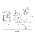
- FIG. 6 depicts an expanded view of the hinge assembly, according to an embodiment.
- FIG. 7 depicts a partial expanded view of the hinge assembly, according to an embodiment.
- FIG. 8 depicts an assembly view of the hinge assembly, according to an embodiment.
- Dust shrouds are used in a variety of power tools to keep dust and debris away from the user. Dust shrouds also protect the user from inadvertent contact with the grinding wheel. Some conventional guards only partially cover an arcural portion of the grinding wheel, leaving a portion of the grinding wheel edge exposed.
- the shroud of the present invention fully encloses an upper surface and circumferential edges of the grinding wheel.
- the shroud includes a side door to partially expose an edge of the grinding wheel.
- the shroud door includes a hinge that allows the user to optionally open or close the door. The door extends from the shroud body to fully enclose the grinding wheel in the closed position. When the door is opened, it lifts above a portion of the grinding wheel to partially expose an edge and upper surface of the grinding wheel.
- the hinge utilizes a cam/spring mechanism to bias the shroud in the open or closed position.
- FIGS. 1-5 depict a shroud 200 including a shroud body 202 and a shroud door 204 attached to the shroud body 202 via a hinge assembly 100 including a cam/spring mechanism, according to an embodiment.
- hinge assembly 100 includes a shroud-side hinge member 102 secured to the shroud body 202 , and two-piece door-side hinge members 122 and 132 secured to the shroud door 204 .
- FIGS. 1-5 depict various views of the hinge assembly 100 mounted on the shroud 200 .
- first and second door-side hinge members 122 and 132 are shown in clear plastic for illustration purposes to make the internal components of the hinge assembly 100 visible.
- FIGS. 4 and 5 depict the shroud door 204 in closed and open positions, respectively.
- FIGS. 6-8 depict expanded views of the hinge assembly 100 components, according to an embodiment.
- Shroud-side hinge member 102 in an embodiment, includes an elongated member 104 and two shroud attachment members 106 a and 106 b disposed at two ends of the elongated member 104 .
- First and second shroud attachment members 106 a and 106 b include holes 108 used to secure the shroud-side hinge 102 to the shroud body 202 via pins and/or screws.
- first and second cylindrical members 110 and 111 extend towards each other from first and second shroud attachment members 106 a and 106 b .
- First shroud attachment member 106 a includes two recessed cam surfaces 116 around the periphery of the first cylindrical member 110 .
- the second cylindrical member 111 includes a stepped cylindrical member (also referred to as pin-shaped member) 112 having a smaller diameter that the second cylindrical member 111 .
- the pin-shaped member 112 extends from the second cylindrical member 111 towards and substantially close to the first cylindrical member 110 .
- first and second door-side hinge members 122 and 132 mate together around cylindrical members 110 and 111 of shroud-side hinge member 102 .
- the door-side hinge members 122 and 132 include matching holes 123 and 133 for attachment to the shroud door 204 via pins and/or screws.
- the door-side hinge members 122 and 132 include first channels 128 and 138 , respectively, which mate together around first cylindrical portion 110 of the shroud-side hinge member 102 .
- An upper portion of each of the first channels 128 and 138 includes outwardly-projecting cam surfaces 130 and 140 that engage two corresponding recessed cam surfaces 116 of the shroud attachment member 106 a .
- Cam surfaces 130 and 140 have the same profile as recessed cam surfaces 116 , allowing the door-side hinge members 122 and 132 to move up and down as the shroud door 204 is turned about the hinge.
- the door-side hinge members 122 and 132 also include second channels 124 and 134 , respectively, which mate together around second cylindrical portion 111 and spring 114 of shroud-side hinge member 102 .
- the door-side hinge members 122 and 132 further each include narrower third channels 126 and 136 , respectively, which are indented with respect to the second channels 124 and 134 .
- Third channels 126 and 136 mate together around the pin-shaped member 112 of the shroud-side hinge member 102 .
- projections 152 and recesses 154 are provided around the third channels 126 and 136 , respectively. Projections 152 fit into recesses 154 for proper alignment of the first and second door-side hinge members 122 and 132 , yet together form a circular channel around the pin-shaped member 112 .
- an axial compression spring 114 is arranged around the pin-shaped member 112 .
- a first end of the spring 114 rests against a wall of the second cylindrical member 111 of the shroud-side hinge member 102 .
- a second end of the spring 114 engages a wall formed by the third channels 126 and 136 of the door-side hinge members 122 and 132 .
- the spring 144 biases the door-side hinge members 122 and 132 towards the first shroud attachment member 106 a , forcing projecting cam surfaces 130 and 140 into the corresponding recessed cam surfaces 116 in the open and closed positions of the shroud door 204 .
- FIG. 2 depicts the hinge assembly 100 as the shroud door 204 is opened (i.e., rotated from a closed position to an open position), according to an embodiment.
- FIG. 3 depicts a zoomed-in view of FIG. 2 , showing the engagement of the cam surfaces 140 and 116 as the shroud door 204 is opened.
- FIG. 4 depicts a perspective view of the shroud 200 as the shroud door 204 is fully closed, according to an embodiment.
- FIG. 5 depicts a perspective view of the shroud 200 as the shroud door 204 is fully opened.
- projected cam surface 130 and 140 of the door-side hinge members 122 and 132 engages the mating recessed cam surfaces 116 of the shroud-side hinge member 102 (only one of which can be seen).
- cam surfaces 130 and 140 of the door-side hinge members 122 and 132 disengage the mating cam surfaces 116 of the shroud-side hinge member 102 .
- door-side hinge members 122 and 132 are pushed closer to the second shroud attachment member 106 b and spring 114 is compressed.
- the door-side hinge members 122 and 132 continue to pivot until cam surfaces 130 and 140 once again engage door-side cam surfaces 116 in the open position.
- Spring 114 biases the shroud door 204 to remain in the open position until once again forced closed by the user.
- FIG. 6 depicts an expanded view of the hinge assembly 100 , including the shroud-side hinge member 102 , and door-side hinge members 122 and 132 , according to an embodiment.
- FIG. 7 depicts the first door-side hinge member 122 engaging the shroud-side hinge member 102 , in an embodiment.
- Spring 114 is excluded from this view.
- first and second channels 138 and 134 partially enclose first and second cylindrical members 110 and 111 .
- FIG. 8 depicts the full hinge assembly 100 including the two door-side hinge members 122 and 132 mating, according to an embodiment.
- hinge assembly used for a shroud door in an angle grinder, according to an exemplary embodiment of the invention. It is noted that hinge assembly of the present application may be used in various type of application or devices, such as home appliances, storage sheds, etc., where it is desired to attach a door to a main body or a support structure biasedly in an open or closed position. It is further noted that while the door-side hinge members 122 and 132 are illustratively depicted as two separate members mated together, the door-side hinge member may be made of a single piece.
- shroud-side hinge member and the door-side hinge member may be switched, so that the door-side hinge member includes cylindrical portions for accommodating the spring, and the shroud-side hinge member includes the cylindrical members to house around the spring.
- the shroud-side hinge member may be provided with a projected cam surface and the door-side hinge member with a corresponding recessed cam surface.
Abstract
Description
- 100 hinge assembly
- 102 shroud-side hinge member
- 104 elongated member
- 106 a first shroud attachment member
- 106 b second shroud attachment member
- 108 hole
- 110 first cylindrical member
- 111 second cylindrical member
- 112 stepped cylindrical (i.e., pin-shaped) member
- 114 spring
- 116 recessed cam surface
- 122 first door-side hinge member
- 123 hole
- 124 second channel
- 126 third channel
- 128 first channel
- 130 outwardly-projecting cam surface
- 132 second door-side hinge member
- 133 hole
- 134 second channel
- 136 third channel
- 138 first channel
- 140 outwardly-projecting cam surface
- 152 projections
- 154 recesses
- 200 shroud
- 202 shroud body
- 204 shroud door
Claims (18)
Priority Applications (1)
| Application Number | Priority Date | Filing Date | Title |
|---|---|---|---|
| US14/264,607 US9289879B2 (en) | 2013-05-02 | 2014-04-29 | Hinge assembly for an angle grinder dust shroud |
Applications Claiming Priority (2)
| Application Number | Priority Date | Filing Date | Title |
|---|---|---|---|
| US201361818612P | 2013-05-02 | 2013-05-02 | |
| US14/264,607 US9289879B2 (en) | 2013-05-02 | 2014-04-29 | Hinge assembly for an angle grinder dust shroud |
Publications (2)
| Publication Number | Publication Date |
|---|---|
| US20140329447A1 US20140329447A1 (en) | 2014-11-06 |
| US9289879B2 true US9289879B2 (en) | 2016-03-22 |
Family
ID=50677991
Family Applications (1)
| Application Number | Title | Priority Date | Filing Date |
|---|---|---|---|
| US14/264,607 Active US9289879B2 (en) | 2013-05-02 | 2014-04-29 | Hinge assembly for an angle grinder dust shroud |
Country Status (2)
| Country | Link |
|---|---|
| US (1) | US9289879B2 (en) |
| EP (1) | EP2799184B1 (en) |
Cited By (3)
| Publication number | Priority date | Publication date | Assignee | Title |
|---|---|---|---|---|
| US20170165808A1 (en) * | 2015-12-15 | 2017-06-15 | John P. Buser | Adaptive Dust Shield Device Having Zero Standoff Capability |
| US10377007B2 (en) | 2016-07-13 | 2019-08-13 | The Boeing Company | Manufacturing byproduct collection systems and methods |
| US10981679B2 (en) | 2017-08-04 | 2021-04-20 | Rocket Lab Usa, Inc. | Satellite deployer door release mechanism |
Families Citing this family (8)
| Publication number | Priority date | Publication date | Assignee | Title |
|---|---|---|---|---|
| DE102012111987A1 (en) * | 2012-12-07 | 2014-06-12 | Flex-Elektrowerkzeuge Gmbh | Hand held grinding machine |
| DE102012111989A1 (en) | 2012-12-07 | 2014-06-12 | Flex-Elektrowerkzeuge Gmbh | Hand held grinding machine |
| JP6667236B2 (en) * | 2015-09-10 | 2020-03-18 | 株式会社マキタ | Grinders, covers and cover sets |
| JP6634248B2 (en) * | 2015-09-10 | 2020-01-22 | 株式会社マキタ | Grinders and covers |
| JP6531337B1 (en) * | 2018-10-06 | 2019-06-19 | 株式会社ナカヤ | Electric grinder with dust control function |
| US11123839B2 (en) | 2018-10-23 | 2021-09-21 | Dustless Depot Llc | Grinder dust shroud with input shaft gasket and adjustable mounting mechanism |
| USD908149S1 (en) * | 2018-10-23 | 2021-01-19 | Dustless Depot Llc | Angle grinder dust shroud with variable position slots for mounting brackets |
| US11273505B2 (en) | 2019-03-27 | 2022-03-15 | Dustless Depot, Llc | Circular saw dust collection shroud |
Citations (48)
| Publication number | Priority date | Publication date | Assignee | Title |
|---|---|---|---|---|
| US57113A (en) | 1866-08-14 | Improvement in corn-harvesters | ||
| US496160A (en) | 1893-04-25 | Spring-hinge | ||
| US1186294A (en) | 1916-02-16 | 1916-06-06 | Charles Diener | Spring-hinge. |
| US1270430A (en) | 1916-09-21 | 1918-06-25 | Emanuel A Martin | Tool-guard. |
| US2384243A (en) | 1944-02-16 | 1945-09-04 | Flohr Andrew | Guard for emery wheels and the like |
| US2735144A (en) * | 1956-02-21 | Hinge assemblies for swinging doors | ||
| US2801654A (en) | 1954-04-08 | 1957-08-06 | Utz Friedrich | Guard for motor-driven hand circular saw |
| DE1068145B (en) | 1959-10-29 | Robert Bosch G.M.B.H., Stuttgart | Hand grinder with a hinged protective cover | |
| US2968830A (en) * | 1958-02-20 | 1961-01-24 | Robart Partitions Inc | Gravity door hinge assembly |
| US3335454A (en) * | 1965-08-18 | 1967-08-15 | Amerock Corp | Spring actuated hinge |
| US3550186A (en) * | 1968-12-13 | 1970-12-29 | Hyer Hardware Mfg Co | Self-closing hinge |
| US3568241A (en) * | 1969-05-14 | 1971-03-09 | U S Ind Corp | Hinge |
| US3673744A (en) | 1971-02-12 | 1972-07-04 | Anders Oimoen | Portable grinder |
| US3837043A (en) * | 1973-04-17 | 1974-09-24 | Keystone Consolidated Ind Inc | Integral spring and cam unit |
| US3919890A (en) * | 1973-04-18 | 1975-11-18 | Keeler Brass Co | Door actuator |
| US3955241A (en) * | 1975-10-16 | 1976-05-11 | Weber-Knapp Company | Cam operated spring biased counterbalance hinge mechanism for cabinet lid or the like |
| US3975794A (en) * | 1974-11-22 | 1976-08-24 | Vollrath Refrigeration, Inc. | Spring hinge |
| US4069568A (en) | 1976-11-10 | 1978-01-24 | Shuichi Sakamoto | Rotary rasping surface scarifying attachment with tilting base |
| DE2539762C3 (en) | 1975-09-06 | 1978-05-18 | Hardo 2000 Hamburg Heuer | Protective and suction hood for hand grinding and polishing machines |
| US4215449A (en) * | 1978-09-15 | 1980-08-05 | Standard Keil Hardware Manufacturing Co. | Self-closing hinge |
| US4607760A (en) * | 1985-07-25 | 1986-08-26 | Roche John N | Closure for a pressurized chamber |
| US4622782A (en) | 1985-08-09 | 1986-11-18 | Roestenberg Jerome R | Sander shield |
| US4819298A (en) * | 1987-09-04 | 1989-04-11 | Karl Lautenschlager Gmbh & Co. Kg | Self-closing hinge for corner cabinets |
| US4921024A (en) | 1989-10-16 | 1990-05-01 | Blount, Inc. | Method and apparatus to fell a tree |
| US4991259A (en) | 1989-08-24 | 1991-02-12 | Kason Industries, Inc. | Butt mounted riser hinge |
| US5109571A (en) * | 1989-10-11 | 1992-05-05 | Sugatsune Industrial Co., Ltd. | Door hinge with movable and fixed cams |
| US5383253A (en) * | 1992-05-07 | 1995-01-24 | Lin; Yeon-Yu | Hydraulic buffer hinge |
| US5546633A (en) * | 1994-11-22 | 1996-08-20 | Liu; Sunny | Hinge |
| US5709597A (en) | 1995-11-21 | 1998-01-20 | Sarantitis; Andreas I. | Pivotal vacuum shield for an abrading device |
| US6108912A (en) | 1998-12-23 | 2000-08-29 | Radigan; Michael C. | Dust collecting shield for power tools |
| US20010004776A1 (en) * | 1998-05-01 | 2001-06-28 | Katoh Electrical Machinery Co. Ltd. | Hinge device for supporting seat and seat lid of toilet bowl openably and closably |
| US6471574B1 (en) | 1999-08-03 | 2002-10-29 | Hilti Aktiengesellschaft | Dust protection cover for a rotary grinding tool |
| US6699114B1 (en) | 2002-04-26 | 2004-03-02 | Benedict Engineering Company, Inc. | Pivotal guards for power hand tools with rotating discs |
| US7000289B2 (en) * | 2001-02-09 | 2006-02-21 | Poly-Tech Industrial, Llc | Gravity hinge |
| FR2882949A3 (en) | 2005-03-14 | 2006-09-15 | M B H Dev Sarl | Angle sander-grinder e.g. suction angle sander-grinder, for suction block, has casing with retractable sector arranged with prehension tab that is seized and raised against tensioning of spring while freeing access to grinding wheel |
| DE102006041671A1 (en) | 2006-09-06 | 2008-03-27 | Robert Bosch Gmbh | Protective hood of a hand tool machine |
| US20080168667A1 (en) | 2005-11-02 | 2008-07-17 | David Spinato | Portable cutting device with guiding guard |
| US20090186559A1 (en) | 2008-01-21 | 2009-07-23 | Michael Loveless | Dust shroud with access hatch retention mechanism |
| US7596872B2 (en) | 2006-07-27 | 2009-10-06 | Robert Bosch Gmbh | Cutting attachment with a removable cover for rotary hand tools |
| EP2163344A2 (en) | 2008-09-12 | 2010-03-17 | Protool GmbH | Manually operated machine tool with a side edge cover |
| US20100275413A1 (en) * | 2007-11-02 | 2010-11-04 | Laird Technologies Korea Yh | Auto hinge of module of cellular phone |
| US20110021121A1 (en) | 2009-07-21 | 2011-01-27 | Spencer Loveless | Angle grinder dust shroud with slideable access hatch |
| EP2163356B1 (en) | 2008-09-12 | 2011-11-02 | Protool GmbH | Hand-held power tool with a covering cap and a dust removal connection |
| US8137165B2 (en) | 2008-01-15 | 2012-03-20 | Dust Collection Products, Llc | Dust shroud with adjustable mounting mechanism |
| EP2269771B1 (en) | 2009-01-29 | 2012-07-18 | Nakaya Co., Ltd. | Dust collecting cover |
| US8438703B2 (en) * | 2011-06-10 | 2013-05-14 | Amesbury Group, Inc. | Positionable hinge |
| US8732906B1 (en) * | 2009-02-18 | 2014-05-27 | Jan van Gennep | Locking hinge assembly |
| US8800109B1 (en) * | 2013-02-06 | 2014-08-12 | Kason Industries, Inc. | Adjustable anti-sag hinge |
Family Cites Families (1)
| Publication number | Priority date | Publication date | Assignee | Title |
|---|---|---|---|---|
| US7988538B2 (en) | 2006-10-13 | 2011-08-02 | Black & Decker Inc. | Large angle grinder |
-
2014
- 2014-04-29 US US14/264,607 patent/US9289879B2/en active Active
- 2014-05-01 EP EP14166816.0A patent/EP2799184B1/en active Active
Patent Citations (50)
| Publication number | Priority date | Publication date | Assignee | Title |
|---|---|---|---|---|
| US57113A (en) | 1866-08-14 | Improvement in corn-harvesters | ||
| US496160A (en) | 1893-04-25 | Spring-hinge | ||
| US2735144A (en) * | 1956-02-21 | Hinge assemblies for swinging doors | ||
| DE1068145B (en) | 1959-10-29 | Robert Bosch G.M.B.H., Stuttgart | Hand grinder with a hinged protective cover | |
| US1186294A (en) | 1916-02-16 | 1916-06-06 | Charles Diener | Spring-hinge. |
| US1270430A (en) | 1916-09-21 | 1918-06-25 | Emanuel A Martin | Tool-guard. |
| US2384243A (en) | 1944-02-16 | 1945-09-04 | Flohr Andrew | Guard for emery wheels and the like |
| US2801654A (en) | 1954-04-08 | 1957-08-06 | Utz Friedrich | Guard for motor-driven hand circular saw |
| US2968830A (en) * | 1958-02-20 | 1961-01-24 | Robart Partitions Inc | Gravity door hinge assembly |
| US3335454A (en) * | 1965-08-18 | 1967-08-15 | Amerock Corp | Spring actuated hinge |
| US3550186A (en) * | 1968-12-13 | 1970-12-29 | Hyer Hardware Mfg Co | Self-closing hinge |
| US3568241A (en) * | 1969-05-14 | 1971-03-09 | U S Ind Corp | Hinge |
| US3673744A (en) | 1971-02-12 | 1972-07-04 | Anders Oimoen | Portable grinder |
| US3837043A (en) * | 1973-04-17 | 1974-09-24 | Keystone Consolidated Ind Inc | Integral spring and cam unit |
| US3919890A (en) * | 1973-04-18 | 1975-11-18 | Keeler Brass Co | Door actuator |
| US3975794A (en) * | 1974-11-22 | 1976-08-24 | Vollrath Refrigeration, Inc. | Spring hinge |
| DE2539762C3 (en) | 1975-09-06 | 1978-05-18 | Hardo 2000 Hamburg Heuer | Protective and suction hood for hand grinding and polishing machines |
| US3955241A (en) * | 1975-10-16 | 1976-05-11 | Weber-Knapp Company | Cam operated spring biased counterbalance hinge mechanism for cabinet lid or the like |
| US4069568A (en) | 1976-11-10 | 1978-01-24 | Shuichi Sakamoto | Rotary rasping surface scarifying attachment with tilting base |
| US4215449A (en) * | 1978-09-15 | 1980-08-05 | Standard Keil Hardware Manufacturing Co. | Self-closing hinge |
| US4607760A (en) * | 1985-07-25 | 1986-08-26 | Roche John N | Closure for a pressurized chamber |
| US4622782A (en) | 1985-08-09 | 1986-11-18 | Roestenberg Jerome R | Sander shield |
| US4819298A (en) * | 1987-09-04 | 1989-04-11 | Karl Lautenschlager Gmbh & Co. Kg | Self-closing hinge for corner cabinets |
| US4991259A (en) | 1989-08-24 | 1991-02-12 | Kason Industries, Inc. | Butt mounted riser hinge |
| US5109571A (en) * | 1989-10-11 | 1992-05-05 | Sugatsune Industrial Co., Ltd. | Door hinge with movable and fixed cams |
| US4921024A (en) | 1989-10-16 | 1990-05-01 | Blount, Inc. | Method and apparatus to fell a tree |
| US5383253A (en) * | 1992-05-07 | 1995-01-24 | Lin; Yeon-Yu | Hydraulic buffer hinge |
| US5546633A (en) * | 1994-11-22 | 1996-08-20 | Liu; Sunny | Hinge |
| US5709597A (en) | 1995-11-21 | 1998-01-20 | Sarantitis; Andreas I. | Pivotal vacuum shield for an abrading device |
| US20010004776A1 (en) * | 1998-05-01 | 2001-06-28 | Katoh Electrical Machinery Co. Ltd. | Hinge device for supporting seat and seat lid of toilet bowl openably and closably |
| US6108912A (en) | 1998-12-23 | 2000-08-29 | Radigan; Michael C. | Dust collecting shield for power tools |
| US6471574B1 (en) | 1999-08-03 | 2002-10-29 | Hilti Aktiengesellschaft | Dust protection cover for a rotary grinding tool |
| EP1074341B1 (en) | 1999-08-03 | 2005-03-16 | HILTI Aktiengesellschaft | Dust protective cover for surface grinding tool |
| US7000289B2 (en) * | 2001-02-09 | 2006-02-21 | Poly-Tech Industrial, Llc | Gravity hinge |
| US6699114B1 (en) | 2002-04-26 | 2004-03-02 | Benedict Engineering Company, Inc. | Pivotal guards for power hand tools with rotating discs |
| FR2882949A3 (en) | 2005-03-14 | 2006-09-15 | M B H Dev Sarl | Angle sander-grinder e.g. suction angle sander-grinder, for suction block, has casing with retractable sector arranged with prehension tab that is seized and raised against tensioning of spring while freeing access to grinding wheel |
| US20080168667A1 (en) | 2005-11-02 | 2008-07-17 | David Spinato | Portable cutting device with guiding guard |
| US7596872B2 (en) | 2006-07-27 | 2009-10-06 | Robert Bosch Gmbh | Cutting attachment with a removable cover for rotary hand tools |
| DE102006041671A1 (en) | 2006-09-06 | 2008-03-27 | Robert Bosch Gmbh | Protective hood of a hand tool machine |
| US20100275413A1 (en) * | 2007-11-02 | 2010-11-04 | Laird Technologies Korea Yh | Auto hinge of module of cellular phone |
| US8137165B2 (en) | 2008-01-15 | 2012-03-20 | Dust Collection Products, Llc | Dust shroud with adjustable mounting mechanism |
| US20090186559A1 (en) | 2008-01-21 | 2009-07-23 | Michael Loveless | Dust shroud with access hatch retention mechanism |
| US8133094B2 (en) | 2008-01-21 | 2012-03-13 | Dust Collection Products, Llc | Dust shroud with access hatch retention mechanism |
| EP2163356B1 (en) | 2008-09-12 | 2011-11-02 | Protool GmbH | Hand-held power tool with a covering cap and a dust removal connection |
| EP2163344A2 (en) | 2008-09-12 | 2010-03-17 | Protool GmbH | Manually operated machine tool with a side edge cover |
| EP2269771B1 (en) | 2009-01-29 | 2012-07-18 | Nakaya Co., Ltd. | Dust collecting cover |
| US8732906B1 (en) * | 2009-02-18 | 2014-05-27 | Jan van Gennep | Locking hinge assembly |
| US20110021121A1 (en) | 2009-07-21 | 2011-01-27 | Spencer Loveless | Angle grinder dust shroud with slideable access hatch |
| US8438703B2 (en) * | 2011-06-10 | 2013-05-14 | Amesbury Group, Inc. | Positionable hinge |
| US8800109B1 (en) * | 2013-02-06 | 2014-08-12 | Kason Industries, Inc. | Adjustable anti-sag hinge |
Non-Patent Citations (1)
| Title |
|---|
| European Search Report, The Hague Aug. 2014. |
Cited By (10)
| Publication number | Priority date | Publication date | Assignee | Title |
|---|---|---|---|---|
| US20170165808A1 (en) * | 2015-12-15 | 2017-06-15 | John P. Buser | Adaptive Dust Shield Device Having Zero Standoff Capability |
| US10035240B2 (en) * | 2015-12-15 | 2018-07-31 | Shave Away Europe, Inc. | Adaptive dust shield device having zero standoff capability |
| US10377007B2 (en) | 2016-07-13 | 2019-08-13 | The Boeing Company | Manufacturing byproduct collection systems and methods |
| US10981679B2 (en) | 2017-08-04 | 2021-04-20 | Rocket Lab Usa, Inc. | Satellite deployer door release mechanism |
| US11059609B2 (en) | 2017-08-04 | 2021-07-13 | Rocket Lab Usa, Inc. | Satellite deployer with externally adjustable payload restraint |
| US11066192B2 (en) * | 2017-08-04 | 2021-07-20 | Rocket Lab Usa, Inc. | Satellite deployer door with clutch bearing |
| US11148830B2 (en) | 2017-08-04 | 2021-10-19 | Rocket Lab Usa, Inc. | Satellite deployer with composite guide rail |
| US20210394934A1 (en) * | 2017-08-04 | 2021-12-23 | Rocket Lab Usa, Inc. | Satellite deployer with composite guide rail |
| US11794928B2 (en) | 2017-08-04 | 2023-10-24 | Rocket Lab Usa, Inc. | Satellite deployer with externally adjustable payload restraint |
| US11814194B2 (en) * | 2017-08-04 | 2023-11-14 | Rocket Lab Usa, Inc. | Satellite deployer with composite guide rail |
Also Published As
| Publication number | Publication date |
|---|---|
| EP2799184A1 (en) | 2014-11-05 |
| EP2799184B1 (en) | 2016-03-23 |
| US20140329447A1 (en) | 2014-11-06 |
Similar Documents
| Publication | Publication Date | Title |
|---|---|---|
| US9289879B2 (en) | Hinge assembly for an angle grinder dust shroud | |
| TWI465325B (en) | Verschlussmechanismus | |
| US9398971B2 (en) | Hinge for an orthopedic brace | |
| US8690459B2 (en) | Protection cap for optical fiber adapter | |
| US11235447B2 (en) | Ratchet wrench | |
| US11072052B2 (en) | Guard assembly for a power tool | |
| AU2014100770A4 (en) | Detachable blades for a ceiling fan | |
| US20120180320A1 (en) | Folding knife | |
| US8459145B2 (en) | Faucet control handle structure | |
| JP6044718B2 (en) | Grinder | |
| US20120023751A1 (en) | Structure of a Cutting Tool | |
| US20220400824A1 (en) | Three-proof earbuds box protective case | |
| US7121362B2 (en) | Electrical hand tool with a position adjustable battery pack | |
| US10994430B2 (en) | Utility knife with dual blades | |
| US9339127B1 (en) | Holding device for tool | |
| US7070437B1 (en) | CPU socket with guiding slots and guiding bosses to ensure smooth movement of the cover relative to the base | |
| US7407167B1 (en) | Roller skate shoe with roller assembly | |
| US20170009496A1 (en) | Locking device and locking device mounting method | |
| US8024840B2 (en) | Hinge | |
| US9958002B2 (en) | Dust-proof safety hook | |
| JP4853785B2 (en) | Anti-theft cover | |
| US20130087218A1 (en) | Assembly structure of faucet control handle | |
| US8982568B2 (en) | Battery cover latching structure and electronic device employing same | |
| US20130105192A1 (en) | Protective cover mechanism and electronic device using same | |
| US20110262125A1 (en) | Camera |
Legal Events
| Date | Code | Title | Description |
|---|---|---|---|
| AS | Assignment |
Owner name: BLACK & DECKER INC., DELAWARE Free format text: ASSIGNMENT OF ASSIGNORS INTEREST;ASSIGNORS:COPELAND, EARNEST N.;CIRINCIONE, ROBERT J., II;REEL/FRAME:034047/0719 Effective date: 20141023 |
|
| STCF | Information on status: patent grant |
Free format text: PATENTED CASE |
|
| MAFP | Maintenance fee payment |
Free format text: PAYMENT OF MAINTENANCE FEE, 4TH YEAR, LARGE ENTITY (ORIGINAL EVENT CODE: M1551); ENTITY STATUS OF PATENT OWNER: LARGE ENTITY Year of fee payment: 4 |
|
| MAFP | Maintenance fee payment |
Free format text: PAYMENT OF MAINTENANCE FEE, 8TH YEAR, LARGE ENTITY (ORIGINAL EVENT CODE: M1552); ENTITY STATUS OF PATENT OWNER: LARGE ENTITY Year of fee payment: 8 |