US9299132B2 - Automatically determining the size of a blur kernel - Google Patents
Automatically determining the size of a blur kernel Download PDFInfo
- Publication number
- US9299132B2 US9299132B2 US14/061,098 US201314061098A US9299132B2 US 9299132 B2 US9299132 B2 US 9299132B2 US 201314061098 A US201314061098 A US 201314061098A US 9299132 B2 US9299132 B2 US 9299132B2
- Authority
- US
- United States
- Prior art keywords
- image
- blur kernel
- size
- value
- blur
- Prior art date
- Legal status (The legal status is an assumption and is not a legal conclusion. Google has not performed a legal analysis and makes no representation as to the accuracy of the status listed.)
- Active, expires
Links
- 238000000034 method Methods 0.000 claims abstract description 108
- 238000004513 sizing Methods 0.000 claims description 26
- 230000035939 shock Effects 0.000 claims description 3
- 238000010586 diagram Methods 0.000 description 28
- 230000006870 function Effects 0.000 description 17
- 230000015654 memory Effects 0.000 description 17
- 238000002156 mixing Methods 0.000 description 13
- 230000008569 process Effects 0.000 description 11
- 238000012545 processing Methods 0.000 description 10
- 230000000875 corresponding effect Effects 0.000 description 8
- 230000033001 locomotion Effects 0.000 description 6
- 239000000203 mixture Substances 0.000 description 6
- 239000003086 colorant Substances 0.000 description 4
- 238000004891 communication Methods 0.000 description 4
- 230000003993 interaction Effects 0.000 description 4
- 230000002441 reversible effect Effects 0.000 description 4
- 230000003068 static effect Effects 0.000 description 4
- 230000002596 correlated effect Effects 0.000 description 3
- 238000005259 measurement Methods 0.000 description 3
- 230000003287 optical effect Effects 0.000 description 3
- 230000004044 response Effects 0.000 description 3
- 230000009471 action Effects 0.000 description 2
- 230000001413 cellular effect Effects 0.000 description 2
- 230000008859 change Effects 0.000 description 2
- 230000001276 controlling effect Effects 0.000 description 2
- 238000005516 engineering process Methods 0.000 description 2
- 230000002349 favourable effect Effects 0.000 description 2
- 238000007726 management method Methods 0.000 description 2
- 238000012986 modification Methods 0.000 description 2
- 230000004048 modification Effects 0.000 description 2
- 238000005457 optimization Methods 0.000 description 2
- 230000036961 partial effect Effects 0.000 description 2
- 230000002829 reductive effect Effects 0.000 description 2
- 229920006395 saturated elastomer Polymers 0.000 description 2
- 238000012800 visualization Methods 0.000 description 2
- 238000007792 addition Methods 0.000 description 1
- 238000003491 array Methods 0.000 description 1
- 230000009286 beneficial effect Effects 0.000 description 1
- 230000005540 biological transmission Effects 0.000 description 1
- 238000013500 data storage Methods 0.000 description 1
- 230000001419 dependent effect Effects 0.000 description 1
- 238000003708 edge detection Methods 0.000 description 1
- 230000000694 effects Effects 0.000 description 1
- 230000007274 generation of a signal involved in cell-cell signaling Effects 0.000 description 1
- 238000009499 grossing Methods 0.000 description 1
- 230000008676 import Effects 0.000 description 1
- 230000006872 improvement Effects 0.000 description 1
- 230000002452 interceptive effect Effects 0.000 description 1
- 239000004973 liquid crystal related substance Substances 0.000 description 1
- 239000011159 matrix material Substances 0.000 description 1
- 230000007246 mechanism Effects 0.000 description 1
- 230000035755 proliferation Effects 0.000 description 1
- 230000003252 repetitive effect Effects 0.000 description 1
- 238000012552 review Methods 0.000 description 1
- 230000008054 signal transmission Effects 0.000 description 1
- 239000000126 substance Substances 0.000 description 1
- 230000001629 suppression Effects 0.000 description 1
- 230000007704 transition Effects 0.000 description 1
- 230000000007 visual effect Effects 0.000 description 1
Images


Classifications
-
- G06T5/73—
-
- G—PHYSICS
- G06—COMPUTING; CALCULATING OR COUNTING
- G06T—IMAGE DATA PROCESSING OR GENERATION, IN GENERAL
- G06T5/00—Image enhancement or restoration
- G06T5/001—Image restoration
- G06T5/003—Deblurring; Sharpening
-
- G—PHYSICS
- G06—COMPUTING; CALCULATING OR COUNTING
- G06F—ELECTRIC DIGITAL DATA PROCESSING
- G06F18/00—Pattern recognition
- G06F18/20—Analysing
- G06F18/23—Clustering techniques
-
- G—PHYSICS
- G06—COMPUTING; CALCULATING OR COUNTING
- G06T—IMAGE DATA PROCESSING OR GENERATION, IN GENERAL
- G06T5/00—Image enhancement or restoration
-
- G—PHYSICS
- G06—COMPUTING; CALCULATING OR COUNTING
- G06T—IMAGE DATA PROCESSING OR GENERATION, IN GENERAL
- G06T7/00—Image analysis
- G06T7/60—Analysis of geometric attributes
-
- G—PHYSICS
- G06—COMPUTING; CALCULATING OR COUNTING
- G06T—IMAGE DATA PROCESSING OR GENERATION, IN GENERAL
- G06T2207/00—Indexing scheme for image analysis or image enhancement
- G06T2207/20—Special algorithmic details
- G06T2207/20024—Filtering details
-
- G—PHYSICS
- G06—COMPUTING; CALCULATING OR COUNTING
- G06T—IMAGE DATA PROCESSING OR GENERATION, IN GENERAL
- G06T2207/00—Indexing scheme for image analysis or image enhancement
- G06T2207/20—Special algorithmic details
- G06T2207/20048—Transform domain processing
-
- G—PHYSICS
- G06—COMPUTING; CALCULATING OR COUNTING
- G06T—IMAGE DATA PROCESSING OR GENERATION, IN GENERAL
- G06T2207/00—Indexing scheme for image analysis or image enhancement
- G06T2207/20—Special algorithmic details
- G06T2207/20172—Image enhancement details
-
- G—PHYSICS
- G06—COMPUTING; CALCULATING OR COUNTING
- G06T—IMAGE DATA PROCESSING OR GENERATION, IN GENERAL
- G06T2207/00—Indexing scheme for image analysis or image enhancement
- G06T2207/20—Special algorithmic details
- G06T2207/20172—Image enhancement details
- G06T2207/20192—Edge enhancement; Edge preservation
Definitions
- the subject matter disclosed herein generally relates to image processing and editing and, more specifically, to automatically determining a size of a blur kernel for removing blur from images.
- Blur may be removed, with varying degrees of success, from a blurred image in an attempt to recover a latent sharp image.
- Known techniques utilize a user defined blur kernel to deblur an entire image using deconvolution.
- One of the most critical parameters in the deblurring process is the size of the blur kernel.
- Most existing methods require blur kernel size as an input parameter, and deblurring performance is often sensitive to the kernel size.
- Blur kernel size set too small or too large relative to the blurred region would result in an incorrectly estimated kernel size, and would not adequately restore a sharp image from a blurred image. Further, the dimensionality of the solution space increases and deblurring is more computationally intensive.
- FIG. 1A is a diagram of a network environment, in accordance with an example embodiment, in which applications for editing images may be deployed.
- FIG. 1B is a block diagram of a user device, in accordance with an example embodiment, configured to edit images.
- FIG. 2 is a block diagram of example components of a blur kernel sizing engine, in accordance with an example embodiment.
- FIG. 3 is a flow diagram of a method, in accordance with an example embodiment, for determining a suggested size of a blur kernel for a blurred region in an image.
- FIG. 4 is a flow diagram of a method, in accordance with an example embodiment, for estimating a size of a blur kernel for a blurred region in an image using an autocorrelation map.
- FIG. 5A shows an example blurred image
- FIG. 5B shows an example latent sharp image for the blurred image of FIG. 5A .
- FIG. 5C shows an example blur kernel for the blurred image of FIG. 5A .
- FIG. 6A shows a screen shot illustrating an autocorrelation map, in accordance with an example embodiment.
- FIG. 6B shows a screen shot illustrating selected connected components within the example autocorrelation map of FIG. 6A .
- FIG. 7 is a flow diagram of a method, in accordance with an example embodiment, for estimating a size of a blur kernel for a blurred image using a latent image process.
- FIG. 8A depicts an example image of blur kernel estimation from a latent image.
- FIG. 8B depicts the measurement of connected components within the blur kernel estimation of FIG. 8A .
- FIG. 9 is a block diagram illustrating example components of a region suggestion engine, in accordance with an example embodiment.
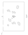
- FIG. 10 shows a screen shot of suggested regions, in accordance with an example embodiment, for automatically estimating a blur kernel.
- FIG. 11 is a flow diagram of a method, in accordance with an example embodiment, for automatically selecting a region in an image for estimating a blur kernel.
- FIG. 12 is an example blurred image showing positioning of a blur kernel at a selected region of the blurred image.
- FIG. 13 is a block diagram of example components of an image deblurring engine, in accordance with an example embodiment, to reduce spatially varying blur using multiple blur kernels.
- FIG. 14 is a flow diagram of a method, in accordance with an example embodiment, for deblurring a blurred image.
- FIG. 15 is an example blurred image showing positioning of multiple blur kernels, in accordance with an example embodiment, at multiple blurred regions of the image.
- FIG. 16A shows a blending region, in accordance with an example embodiment, between a first region, occupied by a first blur kernel, and a second region occupied by a second blur kernel, wherein the first and second regions overlap.
- FIG. 16B is a schematic diagram illustrating a tile-based blending arrangement, in accordance with an example embodiment.
- FIG. 17 shows a graphical user interface (GUI), in accordance with an example embodiment, for editing images.
- GUI graphical user interface
- FIG. 18 is a block diagram of example components of a display interface, in accordance with an example embodiment.
- FIG. 19 is a flow diagram of a method, in accordance with an example embodiment, for presenting user editing controls for deblurring an image.
- FIGS. 20A-20C are exploded views of a blur kernel zone of the GUI of FIG. 17 .
- FIG. 21 is a GUI, in accordance with an example embodiment, illustrating an overlay of a blur kernel on an associated image.
- FIG. 22 is a block diagram illustrating components of a machine, according to some example embodiments, configured to read instructions from a machine-readable medium and perform any one or more of the methodologies described herein.
- a size of one or more blur kernels is estimated automatically, without user input.
- a photo editing application e.g., Adobe® Photoshop®, LightRoom® or the like
- a second value for a second size is determined for the blur kernel for the at least one blurred region.
- a suggested size for the blur kernel is then selected based on the first value and the second value.
- the accessed image is then deblurred by deconvolving the at least one blurred region with a blur kernel of the suggested size.
- a blur kernel may be automatically determined for the same blurred region, and a blur kernel is suggested (e.g., to a user) based on these multiple sizes. Further, different suggested blur kernels may be determined for different regions in the image.
- the first value for the first size of the blur kernel may be determined by an autocorrelation-based size estimator
- the second value for the second size of the blur kernel may be determined by a latent image-based size estimator.
- other blur kernel estimation techniques may be used in other embodiments.
- a derivative image is generated from the accessed image, and the derivative image and the accessed image are autocorrelated to obtain an autocorrelation result.
- the first size for the blur kernel is then determined from the autocorrelation result.
- the first size may be derived from nonzero elements of the autocorrelation result and, optionally, the autocorrelation result is filtered to remove nonzero elements less than a threshold value.
- a latent image may be determined for the accessed image and, thereafter, a blur kernel size is determined from the latent image.
- the suggested size for the blur kernel based on the first value and the second value may be determined using various different mathematical techniques.
- the suggested size may be an average of the first and second values.
- the suggested size may be based on the average of the first value, the second value, and a user defined size.
- systems and methods are described that are configured to deblur images via an image or photo editing application, such as the Adobe® Photoshop® family of applications.
- the technology may be implemented by one or more applications resident on a computing device (e.g., mobile computing device) and/or in a networked environment (e.g., a cloud-based network environment) where processing may, or may not, be distributed.
- FIG. 1A is a diagram of a network environment 100 , in accordance with an example embodiment, for editing images or otherwise processing images (e.g., digital photographs).
- the network environment 100 is shown to include a user device 110 that supports a user interface 115 configured to receive input from an associated user, and configured to present information to the user to allow deblurring of images.
- the user device 110 may include a web browser application, an application (e.g., “app”), or other programs configured to display images and/or allow the user to input or identify images for editing.
- the user interface 115 may facilitate the access of one or more photographic images stored on the user device 110 (e.g., in a photo library), and import images from remote devices and/or applications and so on.
- the user interface 115 may form part of a photo editing application (e.g., Adobe® Photoshop®, LightRoom® or the like).
- the user device 110 is shown to communicate over a network 120 with a server 130 (e.g., a Software as a Service (SAAS) server), which provides a cloud-based and/or network-based image editing application 135 .
- SAAS Software as a Service
- the image editing application 135 may communicate with the user device 110 and its user interface 115 to facilitate the editing of images by the user via the user device 110 .
- the network 120 may be any network that enables communication among machines, databases, and devices (mobile or otherwise). Accordingly, the network 120 may be a wired network, a wireless network (e.g., a mobile or cellular network), a storage area network (SAN), or any suitable combination thereof. In an example embodiment, the network 120 includes one or more portions of a private network, a public network (e.g., the Internet), or combination thereof.
- the user device 110 may be any suitable computing device, such as a desktop computer, a laptop computer, a smart phone, a tablet, a gaming device, or any other computing device configured to facilitate interactions between a user and the image editing application 135 .
- the image editing application 135 may include various components, modules, and/or engines configured to facilitate the deblurring, sharpening, and/or other modifications of images.
- the images may have a single blurred region, a plurality of blurred regions, and/or other artifacts that degrade the quality of the images and hence removal thereof is desired.
- the deblurring of an image includes techniques that attempt to estimate a latent sharp image for a blurred image (image including blurred regions) by convolving an estimated latent sharp image with a blur kernel.
- the blur kernel may be represented by a convolution matrix.
- Deconvolution is an operation that may reverse, change and/or modify blur, distortions, or other imperfections in an image.
- solving for l by deconvolving the blurred image b with the blur kernel k may lead to an enhanced or sharper image where blurring is at least reduced in blurred regions of the image.
- the image editing application 135 may comprise various components to deblur images including, but not limited to, an image deblurring engine 140 , a blur kernel sizing engine 150 , and a region suggestion engine 160 .
- the image deblurring engine 140 may be configured to deblur images having multiple blurred regions (e.g., spatially varying blur)
- the blur kernel sizing engine 150 may be configured to automatically (e.g., without human intervention) determine a size of one or more blur kernels utilized in deblurring images
- the region suggestion engine 160 may be configured to automatically identify and/or suggest regions within a blurred image at which to apply and/or generate blur kernels.
- FIG. 1B is a block diagram of a user device 170 , in accordance with an example embodiment, configured to edit images.
- the user device 170 may be the same or similar to the user device 110 and may be configured to support the image editing application 135 (as a standalone or networked device).
- the user device 170 may store and execute software/instructions to facilitate interactions between a user and the image editing application 135 via the user interface 115 of the user device 110 .
- the image editing application 135 may perform, or cause to be performed, various image editing tasks at different networked locations.
- the image editing application 135 may remotely estimate blur kernels at the server 130 , while locally deblurring images at the device 110 , or vice versa.
- the use of different resources may be user-selectable, such that a user may configure the image editing application 135 to perform certain tasks remotely, or in the cloud, and other tasks locally.
- deblurring an image involves deconvolving one or more blurred regions using at least one blur kernel.
- users attempting to deblur an image having blurred regions may be unable (or of insufficient skill) to define an appropriate size of the blur kernel used to deblur the image.
- the selected blur kernel may be considered an unsuitable kernel, which may not properly or sufficiently deblur the image.
- the selected blur kernel may not properly or sufficiently deblur the image.
- automatically estimating and/or determining the size of blur kernels may provide users with suitable blur kernels of appropriate size to adequately deblur images (e.g., via existing deblurring algorithms and/or the algorithms described herein).
- the automated estimation of the size of the blur kernel is calculated electronically without human input influencing the size of the blur kernel.
- the size of the blur kernel may at least partially be determined based on algorithms that do not depend on user input.
- FIG. 2 is a block diagram of example components (or modules) of a blur kernel sizing engine 150 , in accordance with an example embodiment.
- the example components may be hardware, software, or a combination of hardware and software, and may be executed by one or more processors.
- the blur kernel sizing engine 150 is shown to include an image module 210 and a blur kernel sizing module 220 .
- the blur kernel sizing module 220 may include an autocorrelation-based size estimator 222 to estimate a first size of the blur kernel, a latent image-based size estimator 224 to estimate a second size of the blur kernel, and process the results to suggest or recommend a size of the blur kernel to be used to deblur the image. It is however to be noted that the autocorrelation-based size estimator 222 and the latent image-based size estimator 224 are merely examples of estimators, and that other mathematical techniques may be used in other embodiments.
- the image module 210 may be configured (e.g., a programmed processor) to access an image (e.g., an image stored in a photo library on a device) having at least one blurred region.
- an image e.g., an image stored in a photo library on a device
- a user selects or identifies an image including a region to be deblurred using a graphical user interface, and the image module 210 then accesses the image (e.g., accesses data defining the image) for processing.
- the blur kernel sizing module 220 is configured to estimate a size of a blur kernel for the accessed image using two different sizing estimators.
- the blur kernel sizing module 220 may automatically determine a first value for a first size of a blur kernel for a blurred region using a first sizing estimator (e.g., the autocorrelation-based size estimator 222 ), automatically determine a second value for a second size of the blur kernel using a second, different, size estimator, and select a suggested size for the blur kernel that is based on the first value and the second value, as described in more detail with reference to FIG. 3 .
- the estimated values for the sizes of the blur kernel may however be computed by the same estimator or any one or more estimators.
- FIG. 3 is a flow diagram of a method 300 , in accordance with an example embodiment, for determining a suggested size of a blur kernel for deblurring a blurred region in an image.
- the method 300 may be performed by the blur kernel sizing engine 150 and, accordingly, is described herein merely by way of example with reference thereto. It will be appreciated that the method 300 may be performed on any suitable hardware.
- the blur kernel sizing engine 150 may access data representing an image (herein also referred to as accessing the image) having at least one blurred region (see operation 310 ).
- the image module 210 may access a blurred image including one or more blurred regions.
- the image module 210 may downsample the accessed image in order to reduce noise and/or reduce the size of the blurred regions that are used to estimate the size of a blur kernel.
- the blur kernel sizing engine 150 automatically, without user input, determines a first value for a first size of a blur kernel, and automatically, without user input, determines a second value for the size of the blur kernel to be used in deblurring a region of the image.
- the first size estimator may be an autocorrelation-based size estimator (e.g., the autocorrelation-based size estimator 222 ), which determines an estimated size of the blur kernel based on autocorrelating the accessed image with a derivative of the accessed image, as discussed by way of example below with reference to FIG. 4 .
- the method 300 may then automatically determine a suggested size for the blur kernel based on the first and second values.
- FIG. 4 is a flow diagram of a method 400 , in accordance with an example embodiment, for estimating a size of a blur kernel for a blurred region in an image using an autocorrelation process.
- the method 400 may be performed by the autocorrelation-based size estimator 222 and, accordingly, is described herein merely by way of example with reference thereto. It will be appreciated that the method 400 may be performed on any suitable hardware.
- the autocorrelation of (d*b) is related to the blur kernel k. Therefore, the actual blur size may be related to the nonzero elements in the autocorrelation result. For example, assuming a blur kernel size is generalized as W k ⁇ H k , the size of k**k is (2W k ⁇ 1) ⁇ (2H k ⁇ 1).
- the autocorrelation-based size estimator 222 calculates a derivative for the blurred regions of the accessed image.
- the autocorrelation-based size estimator 222 may apply a differential operator to data representing the accessed image, such as a discrete differential operator d, defined as:
- FIG. 5A shows an example of a blurred image 510
- FIG. 5B shows a latent sharp image 505 corresponding to the blurred image 510
- a corresponding blur kernel 515 is shown in FIG. 5C .
- the autocorrelation-based size estimator 222 may calculate various derivatives of the blurred image 510 , such as first order derivative, a second order derivative, and so on.
- first order derivative a second order derivative
- Other derivative filters may provide similar effects, and they may be used instead.
- the autocorrelation-based size estimator 222 may determine an autocorrelation map for the derivative.
- the autocorrelation map may reflect the autocorrelation between the blurred image 510 and the derivative of the blurred image 510 .
- the autocorrelation-based size estimator 222 may compute the autocorrelation using a Fourier transform, or other similar technique.
- the method 400 applies a threshold filter to the autocorrelation of the blurred image and the derivative thereof.
- the autocorrelation-based size estimator 222 may identify the extent of nonzero elements within the autocorrelation map, and determine the size of the blur kernel based on the nonzero elements (e.g., as described with reference to FIGS. 6A and B below).
- noise and/or repetitive patterns such as textures in the latent image l, may introduce misleading nonzero values, which may cause the autocorrelation result to differ from a delta function.
- the autocorrelation-based size estimator 222 may, therefore, apply a threshold filter to the autocorrelation result to remove small non-zero components (e.g., less than a threshold value) from the autocorrelation result, in order to correctly and/or robustly estimate the extent of nonzero elements caused by the blur kernel k, among other things.
- a threshold filter to remove small non-zero components (e.g., less than a threshold value) from the autocorrelation result, in order to correctly and/or robustly estimate the extent of nonzero elements caused by the blur kernel k, among other things.
- a connected component in the autocorrelation map may be identified (e.g., using the autocorrelation-based size estimator 222 ).
- the autocorrelation-based size estimator 222 may measure a cluster of nonzero elements within the autocorrelation map, which may then define the connected components.
- FIG. 6A shows a screen shot 600 illustrating an example autocorrelation map 605 determined using the method 400 .
- the components are symmetrical.
- FIG. 6B shows a screen shot 610 illustrating selected connected components 615 within the example autocorrelation map 605 .
- the autocorrelation-based size estimator 222 may identify the connected component 615 of nonzero elements centered within an autocorrelation map 605 , and measure the dimensions (e.g., a maximum width and height) of the connected component 615 in a connected component zone, shown as box 620 . The autocorrelation-based size estimator 222 may then determine and/or estimate the size of the blur kernel based on the measured width and height of the connected component 615 .
- the autocorrelation-based size estimator 222 may determine the box 620 is 21 by 21 pixels, and automatically estimate the size (e.g., determine a lower and/or higher value) of the blur kernel to be 21 by 21 pixels, or within a range of sizes that includes the determined size of the box 620 .
- the area or zone of connected components may, in other embodiments, be of different shapes and that a box is merely an example of such a shape.
- the second size estimator (e.g., the latent image-based size estimator 224 ) estimates a size based on an estimated latent image.
- the latent image-based size estimator 224 may automatically generate and/or determine a rough guess or estimate of a latent image l for the blurred image, and use the estimated latent image to automatically determine the size of the blur kernel.
- FIG. 7 is a flow diagram of a method 700 , in accordance with an example embodiment, for estimating a size of a blur kernel for an image using a latent image process.
- the method 700 may be performed by the latent image-based size estimator 224 and, accordingly, is described herein merely by way of example with reference thereto. It will be appreciated that the method 700 may be performed on any suitable hardware.
- the latent image-based size estimator 224 determines an estimated latent image for the accessed image.
- the latent image-based size estimator 224 may apply a shock filter to a blurred image b to restore sharp edges within the image.
- the latent image-based size estimator 224 may then compute one or more gradient maps from the shock filtered result.
- gradient values of small magnitudes e.g., below or equal to a gradient threshold
- a blur kernel may be estimated from the latent image, for example, using the latent image-based size estimator 224 .
- the method 700 may estimate (e.g., using the latent image-based size estimator 224 ) a blur kernel k by solving the following example optimization equation:
- the latent image-based size estimator 224 solves the above equation using Fourier transforms, as follows:
- K ⁇ ( u , v ) P x ⁇ ( u , v ) _ ⁇ D x ⁇ ( u , v ) ⁇ B ⁇ ( u , v ) + P y ⁇ ( u , v ) _ ⁇ D y ⁇ ( u , v ) ⁇ B ⁇ ( u , v ) ⁇ P x ⁇ ( u , v ) ⁇ 2 + ⁇ P y ⁇ ( u , v ) ⁇ 2 + ⁇ ⁇ ( ⁇ D x ⁇ ( u , v ) ⁇ 2 + ⁇ D y ⁇ ( u , v ) ⁇ 2 ) + ⁇
- FIG. 8A depicts an example image 800 of a blur kernel 810 estimated from the estimated latent image, including nonzero elements 815 (see operation 710 in FIG. 7 .).
- nonzero elements of the estimated blur kernel may be measured.
- the latent image-based size estimator 224 may measure the nonzero elements 815 depicted in the blur kernel 810 by using various techniques described herein, such as the techniques described with respect to FIG. 4 .
- the size of the blur kernel may be determined from the nonzero elements 815 .
- FIG. 8B depicts the measurement of connected components 825 within an estimated blur kernel 820 .
- a measured zone (connected component region) illustrated by a box 827 reflects measurement of the connected components 825 .
- the box 827 may have a width of 35 pixels and a height of 31 pixels, and the latent image-based size estimator 224 may automatically estimate the size (e.g., determine a lower and/or higher value) of the blur kernel to be 35 by 31 pixels, or within a range of sizes that includes the determined size of the box 827 .
- the blur kernel sizing engine 150 may receive input from a user which identifies an additional estimated size for the blur kernel.
- estimation of the size of a blur kernel may be based on one or more automated estimations and a user-defined estimation. These estimations may then, for example, be weighted and used to determine the blur kernel size that will be used to deblur the image selected by the user for processing.
- the blur kernel sizing engine 150 may utilize the autocorrelation-based size estimator 222 to estimate a lower or smaller value of the size of the blur kernel (operation 320 ), and may utilize the latent image-based size estimator 224 to estimate a higher or upper value of the size of the blur kernel (operation 330 ).
- the blur kernel sizing engine 150 may utilize the latent image-based size estimator 224 to estimate the lower or smaller value of the size of the blur kernel (operation 320 ), and may utilize the autocorrelation-based size estimator 222 to estimate the higher or upper value of the size of the blur kernel (operation 330 ).
- the blur kernel sizing engine 150 may determine the suggested size for the blur kernel based on the first value and the second value. For example, the blur kernel sizing engine 150 may perform a variety of different determinations or follow various selection criteria or rules when determining the suggested, or actual, size for the blur kernel.
- Example selection criteria or rules may include:
- the blur kernel sizing engine 150 and the methods 300 and 700 utilize one or more size estimation techniques to automatically, with or without user input, determine the size of a blur kernel for an input blurred image.
- deblurring an image may involve applying a blur kernel to a blurred region of an image.
- the systems and methods described herein may automatically select a certain region or part of the image at which to estimate a blur kernel. Such as a region may be selected because the characteristics it may have could facilitate accurately and/or effectively deblurring the entire image.
- the associated blur kernel may then be estimated for the selected region.
- the systems and methods may access input or reference parameters, such a blur kernel size (e.g., a size automatically determined by the blur kernel sizing engine 150 ), and identify a best or suitable region of the image at which to estimate and/or apply the blur kernel.
- a selected or suitable region may be a region that includes edges of objects in the image (e.g., an outline of a person, a tree, etc.), over-exposed pixels within the image, under-exposed pixels within the image, and/or any features within the image that may break the linearity of motion causing blurring of the image (e.g., blurring due to camera movement).
- An additional input parameter may be associated with a user-identified region within the blurred image, and a best or suitable region that is proximate to the user-defined region may be identified. Accordingly, the user may provide an initial reference region (or point in a region), and the user-identified region may be refined or adjusted automatically to enhance deblurring.
- the systems and methods may identify multiple suitable regions (ideally best regions) in which to estimate and/or apply an associated blur kernel.
- FIG. 9 is a block diagram illustrating example components of a region suggestion engine 160 , in accordance with an example embodiment.
- the region suggestion engine 160 is shown to include a plurality of modules that may be implemented in hardware, software, or a combination of hardware and software, and may be executed by one or more processors.
- the region suggestion engine 160 may include an image module 910 , a blur kernel size module 920 , a metrics module 930 , and a region selection module 940 .
- the region suggestion engine 160 may utilize representative 2D discrete arrays for a selected blurred image in order to suggest appropriate (ideally best) regions of the images at which to estimate and/or apply blur kernels.
- a 2D discrete array may often represent a digital image.
- f x ( x,y) may be defined in a similar way.
- other definitions for the partial derivatives are also possible.
- ⁇ f(x,y) is a 2D vector
- ⁇ ⁇ ( ⁇ f ⁇ ( x , y ) ) atan ⁇ ( f y ⁇ ( x , y ) f x ⁇ ( x , y ) )
- the above example 2D discrete array may be utilized to represent a selected blurred image in order to suggest suitable regions of the images at which to estimate and/or apply blur kernels, as described in more detail below.
- the image module 910 is configured to access a blurred image represented by a 2D discrete array.
- the image module 910 which may be similar to the image module 210 , may access an image selected by a user of the image editing application 135 , via the user interface 115 of the user device 110 .
- images may be stored in various different locations (e.g., in a photo library stored on a device or in the cloud) and such access may be directly or via a network (e.g., see FIG. 1 ).
- the blur kernel size module 920 is configured to define a size for a blur kernel associated with the blurred image.
- the blur kernel size module 920 employs similar or the same methodology as described herein with respect to the blur kernel sizing module 220 .
- the blur kernel size module 920 may include one or more blur estimators, such as the autocorrelation-based size estimator 222 and/or the latent image-based size estimator 224 .
- the blur kernel size module 920 may automatically determine a lower value for a size of a blur kernel for the blurred region using a first size estimator, automatically determine an upper value for the size of the blur kernel using a different second size estimator, and determine a size for the blur kernel that is based on the lower and upper value for the size of the blur kernel.
- the image module 910 may access a blurred image, such as a blurred image b, and preprocess the blurred image by downsampling the image with respect to the input blur kernel size, such as a size N k ⁇ N k .
- the downsampling may reduce the image size (e.g., such that computational time is reduced), may reduce the blur, may reduce noise or artifacts, and so on.
- the downsampled image b low may have a size W low ⁇ H low .
- the metrics module 930 may be configured to determine metrics for at least two of the plurality of regions based on a number of edge orientations within a region.
- the metrics module 930 may perform various algorithmic processes to identify image characteristics and/or features associated with favorable or suitable regions within the selected image.
- a suitable region may be any region determined to be favorable for deblurring but may not necessarily be the most suitable region within the blurred image. Such a region deemed suitable may be based on analyzing the image to identify contrast edges of many different directions, and/or few or no corrupted pixels (e.g., saturated pixels) within the selected image.
- the metrics module 930 may identify regions that include objects having edges of different orientations to facilitate estimation by the metrics module 930 of a blur kernel.
- a blur kernel may be selected or defined in a direction orthogonal to an orientation (e.g., edge direction) of a selected edge. For example, to identify a blur kernel of size N k ⁇ N k , a region may include N k different edge directions.
- the variable NumEdgeOrientations(R) is the number of available edge orientations in the selected image.
- M max ⁇ ( ⁇ N k 10 ⁇ , 4 ) .
- variable AvgGradMag(R) is the average gradient magnitude value of the pixels in the region r. For example, when an image region r has more edges of large contrast, then AvgGradMag(R) becomes large, and vice versa.
- AvgGradMag(R) may be defined as:
- AvgGradMag ⁇ ( R ) 1 ⁇ R ⁇ ⁇ ⁇ ( x , y ) ⁇ R ⁇ ⁇ ⁇ ⁇ b low ⁇ ( x , y ) ⁇ .
- variable ClipWeight(R) is defined as:
- ClipWeight ⁇ ( R ) ⁇ ( x , y ) ⁇ R ⁇ ⁇ c ⁇ ( x , y )
- c ⁇ ( x , y ) ⁇ 1 if ⁇ ⁇ c low ⁇ b low ⁇ ( x , y ) ⁇ c up exp ⁇ ( - ⁇ b low ⁇ ( x , y ) - c up ⁇ 2 ⁇ c 2 ) if ⁇ ⁇ b low ⁇ ( x , y ) > c up exp ⁇ ( - ⁇ b low ⁇ ( x , y ) - c low ⁇ 2 ⁇ c 2 ) if ⁇ ⁇ b low ⁇ ( x , y ) ⁇ c up
- c up 220 255
- c low 10 255
- ⁇ ⁇ ⁇ c 40 255 .
- blur kernels when an image includes spatially varying blur, blur kernels may be estimated from regions within a center of the image (or, within a center between the blurred regions). These center-estimated and/or -applied blur kernels may effectively reduce (ideally remove) the spatially varying blur of the entire image.
- the metrics module 930 may apply and/or add a location weight variable to the determined metrics for the regions of the image.
- LocWeight ⁇ ( R ) exp ⁇ ( - ⁇ x R - x C ⁇ 2 + ⁇ y R - y C ⁇ 2 2 ⁇ ⁇ L )
- the metrics module 930 may receive information (e.g., a user input from a mouse, touchpad, touch screen, or the like) that identifies a user-defined location and/or region within the image at which to estimate a blur kernel.
- the metrics module 930 may define and/or modify the weighting function LocWeight(R) as follows:
- LocWeight ⁇ ( R ) exp ⁇ ( - ⁇ x R - x i ⁇ 2 + ⁇ y R - y i ⁇ 2 2 ⁇ ⁇ L )
- the metrics module 930 may determine metrics for regions of varying sizes. For example, small regions (e.g., regions less than a reference size) of an image may include enough characteristics (e.g., edge orientations) to suitably perform blur kernel estimation. The metrics module 930 may then determine metrics for the small regions in order to reduce computation times, avoid regions with corrupted pixels, and so on. Of course, the metrics module 930 may determine metrics for regions within an image based on other processes, techniques, and/or algorithms that include variables associated with edges, edge orientations, and so on, within the regions.
- the region selection module 940 is configured to select a region based on the determined metrics at which to position the blur kernel during deconvolution of the blurred image. For example, the region selection module 940 may select the region or regions associated with the highest values of the usefulness U(R) and/or U′(R).
- the region selection module 940 may consider various region sizes (e.g., using a pre-defined set of scale factors) along with the metrics associated with the region sizes. When a suitable region is identified, the region selection module 940 may select the region with the determined scale factor size and ignore other sizes. However, if a suitable region, or a region not meeting defined criteria, is not found, then the region selection module 940 multiplies a next scale factor with the blur kernel size, and selects a region of that size, until a suitable or best region is identified.
- region sizes e.g., using a pre-defined set of scale factors
- the region selection module 940 may locate a region with a large or largest usefulness U(R) or U′(R), and determine whether the usefulness U(R) or U′(R) is greater than a threshold value, t u
- the threshold value t u may define a minimum or sufficient value for the suitability of a region at which to estimate and/or apply a blur kernel.
- FIG. 10 shows a screen shot 1000 of suggested regions for automatically estimating a blur kernel. More particularly, the screen shot 1000 shows a first region 1010 and a second region 1015 at which to estimate a blur kernel.
- a blur kernel 1020 may be estimated for the first region 1010
- a blur kernel 1025 may be estimated for the second region 1015 .
- the metrics module 930 may then, for example, determine which of the first and the second regions 1010 , 1015 is more suitable for estimating a blur kernel used to deblur the image. For example, the regions may be selected based on a number of edge orientations within each region
- the size of the regions may be modified. For example, the size of each of a plurality of regions may be modified, and metrics for each the plurality of regions having a modified size may then be determined. Thereafter, a region having the modified size that is associated with a metric that satisfies the threshold metric for estimating the blur kernel may be selected.
- the region suggestion engine 160 may perform various techniques to automatically select and/or determine a region within an image at which to estimate a blur kernel and/or apply the blur kernel to deblur the image.
- FIG. 11 is a flow diagram illustrating a method 1100 , in accordance with an example embodiment, for selecting a region in an image for estimating a blur kernel.
- the method 1100 may be performed by the region suggestion engine 160 and, accordingly, is described herein merely by way of example with reference thereto. It will be appreciated that the method 1100 may be performed on any suitable hardware.
- the region suggestion engine 160 accesses a blurred image having a plurality of regions.
- One or more of the regions may be blurred regions.
- the blurred image may be accessed by the image editing application 135 , via the user interface 115 of the user device 110 .
- the region suggestion engine 160 defines a size for each of the plurality of regions.
- the region suggestion engine 160 may preprocess the blurred image by downsampling the image with respect to the input blur kernel size, such as a size N k ⁇ N k .
- the downsampling may reduce the image size and output a downsampled image b low , having a size W low ⁇ H low .
- the downsampling may reduce computational time, may reduce the blur, may reduce noise or artifacts, and so on.
- the region suggestion engine 160 determines metrics for at least two of the plurality of regions, the metrics being based on a number of edge orientations within each region.
- the metrics module 930 may perform various algorithmic processes described herein to identify image characteristics and/or features associated with suitable regions within the accessed image.
- the suitable regions may have contrast edges of many different edge directions, few or no corrupted pixels (e.g., saturated pixels), and so on.
- Example metrics may be based on edge orientations, a gradient magnitude, a clip weight, a location weight, and combinations thereof.
- the region suggestion engine 160 selects a region, based on the determined metrics, at which to estimate and/or position the blur kernel during deconvolution of the blurred image.
- the region selection module 940 may select the region or regions associated with the highest usefulness metric U(R) and/or U′(R) values.
- FIG. 12 is an example of a blurred image 1200 showing positioning of an example blur kernel 1220 at a selected region 1210 of the blurred image 1200 .
- the method 1100 may then, as shown in operation 1150 , estimate a blur kernel for deblurring the image based on the selected region. Thereafter, as shown in operation 1160 , the image may be deblurred using the blur kernel.
- the region suggestion engine 160 may identify multiple suitable regions in the blurred image 1200 for blur kernel estimation.
- the region selection module 940 may determine whether any of the identified regions overlap and, if the regions overlap by more than a certain ratio or reference amount, other suitable regions may then be selected for blur kernel estimation.
- the region suggestion engine 160 may determine a metric for a single region within the image (e.g., a user-defined or center region), and, if the metric indicates the region is suitable for blur kernel estimation, select the single region without calculating metrics for other regions of the image.
- a metric for a single region within the image e.g., a user-defined or center region
- the region suggestion engine 160 may select a region within an image at which to estimate and/or position a blur kernel, in order to deblur the image.
- the image editing application 135 may utilize multiple blur kernels to deblur the photos. For example, a blur kernel may be provided for each different blurred region within an image. Because differences between blur kernels for an image with spatially varying blur may be small, the image editing application 135 may deblur a single, local, region within an image using an associated static blur kernel. Different blur kernels may then be used in other regions and the deblurred results may be combined or stitched together to form a final deblurred image (e.g., see FIG. 15 ).
- FIG. 13 is a block diagram of example components of an image deblurring engine 140 , in accordance with an example embodiment, to reduce (ideally remove) spatially varying blur using multiple blur kernels.
- the image deblurring engine 140 may include one or more modules implemented in hardware, software, or a combination of hardware and software, and that may be executed by one or more processors.
- the image deblurring engine 140 is shown, by way of example, to include an image module 1310 , a blur kernel module 1320 , a kernel positioning module 1330 , and a deblurring module 1340 .
- the image module 1310 is configured to access an image having multiple blurred regions (e.g., two or more), such as a first blurred region and a second blurred region.
- the image module 1310 which may be similar to the image module 210 and/or image module 910 , may access a blurred image resident on a local device, in the cloud, or otherwise.
- the image module 1310 accesses an image input to the image editing application 135 , via the user interface 115 of the user device 110 .
- the blur kernel module 1320 is configured (e.g., programmed) to generate a first blur kernel for the first blurred region and a second blur kernel for the second blurred region.
- the blur kernel module 1320 may generate and/or determine local blur kernels for some or all of the blurred regions within the image using techniques described herein.
- the image editing application 135 may provide a graphical user interface (GUI), such as one or more of the various user interfaces described herein, configured to receive input from a user that specifies local regions within the image for blur kernel estimation.
- GUI graphical user interface
- the blur kernel module 1320 may analyze the image content within the identified region to estimate a static or local blur kernel K for the region.
- the blur kernel module 1320 which may use various techniques for generating blur kernels, such as those described herein, may then create a list of local kernels K 1 , K 2 , . . .
- the image editing application 135 may perform the techniques described herein to automatically suggest the local regions for kernel estimation.
- the blur kernel module 1320 may generate a group of local blur kernels that are used to at least partially (ideally satisfactorily) deblur a local region. Thus, a single blur kernel is not used to deblur all blurred regions of entire image.
- the kernel positioning module 1330 is configured to position the first blur kernel with respect to the first blurred region and position the second blur kernel with respect to the second blurred region based on the position of the first blur kernel. For example, the kernel positioning module 1330 may align the local blur kernels with respect to each other.
- the kernel positioning module 1330 may identify a blur kernel K c having a center position (x c , y c ) that is closest to a center of the image or closest to a focal point of the image (e.g., a focal point identified from metadata associated with the image). Thereafter, the remaining blur kernels are positioned relative to the blur kernel K c , which may define a center kernel or base kernel.
- the kernel positioning module 1330 may identify an optimal shift ( ⁇ x*, ⁇ y*), as follows:
- the deblurring module 1340 is configured (e.g., programmed) to deconvolve the first blurred region with the first blur kernel and deconvolve the second blurred region with the second blur kernel.
- the deblurring module 1340 may perform tile-based multi-kernel deconvolution to deblur the entire image using the aligned, local, static kernels.
- Tile-based multi-kernel deconvolution may comprise dividing up a blurred image into a plurality of regions or tiles that do not overlap.
- the tiles may be rectangular or square tiles that are arranged in a grid.
- the tile size can be a fixed number, such as 512 by 512 pixels.
- the deblurring module 1340 uses each local kernel K i to generate a deconvolution result L i for each local region (e.g., tile) of the image, and may blend the deconvolution results (L i s) together, using various techniques, to form a final, deblurred image.
- FIG. 14 is a flow diagram illustrating a method 1400 , in accordance with an example embodiment, for deblurring a blurred image.
- the method 1400 may be performed by the image deblurring engine 140 and, accordingly, is described herein merely by way of example with reference thereto. However, it will be appreciated that the method 1400 may be performed on any suitable hardware.
- the method 1400 is shown to commence at operation 1410 wherein the image deblurring engine 140 accesses an image having a first blurred region (e.g., centered at (x 1 , y 1 )) and a second blurred region (e.g., centered at (x 2 , y 2 )).
- the image module 1310 may access a blurred image having spatially varying blur, such as two or more blurred regions that are spatially offset.
- a first blur kernel (e.g., K 1 ) is generated for the first blurred region and a second blur kernel (e.g., K 2 ) is generated for the second blurred region.
- the blur kernel module 1320 may generate further local blur kernels for each of the blurred regions within the image.
- the first blur kernel is positioned with respect to the first blurred region
- the second blur kernel is positioned with respect to the second blurred region based on the position of the first blur kernel (see operations 1430 and 1440 ).
- the kernel positioning module 1330 may consider the first blur kernel as a base or center kernel, and locate, position, and/or align the second blur kernel with respect to non-zero elements of the first blur kernel such that an optimal shift between the second blur kernel and the base kernel is maximized or highly correlated.
- FIG. 15 is an example blurred image 1500 showing positioning of multiple blur kernels, in accordance with an example embodiment, at multiple blurred regions of the image 1500 .
- a blur kernel 1515 is positioned proximate to a region 1510
- a blur kernel 1525 is positioned proximate to a region 1520
- a blur kernel 1535 is positioned proximate to a region 1530
- a blur kernel 1545 is positioned proximate to a region 1540 .
- the method 1400 is described with reference to two blur kernels, it is to be appreciated that multiple blur kernels may be utilized (e.g., four blur kernels are shown by way of example in FIG. 15 ).
- the image may be deblurred by deconvolving the first blurred region (e.g., region 1510 ) with the first blur kernel (e.g., blur kernel 1515 ) and deconvolving the second blurred region (e.g., region 1520 ) with the second blur kernel (e.g., blur kernel 1525 ).
- the deblurring module 1340 may generate a deconvolution result for the first blurred region and generate a deconvolution result for the second blurred region, and blend the results to create a final, deblurred image.
- Deconvolution of further blur kernels and further blurred regions may take place (e.g., regions 1530 and 1540 with blur kernels 1535 and 1545 ).
- Deconvolution as described herein, is intended to include a reverse operation of a convolution operation, and, therefore, may reverse, change, and/or modify blur, distortion, or other imperfections in images.
- FIG. 16A shows a diagram 1600 that displays a blending region 1615 between a first region 1610 occupied by a first blur kernel (e.g., blur kernel K1) and a second region 1620 occupied by a second blur kernel (blur kernel K2), wherein the first and second regions 1610 , 1620 overlap.
- a first blur kernel e.g., blur kernel K1
- a second blur kernel blue kernel K2
- the first region 1610 is shown to be centered at (x 1 , y 1 ) in the image and the second region 1620 is centered at (x 2 , y 2 ) in the image.
- deconvolution results L 1 and L 2 may be determined using blur kernels K 1 and K 2 , having centers at pixels (x 1 , y 1 ) and (x 2 , y 2 ), respectively, in the blurred image.
- a spatial distance between the pixel and the two kernel centers ((x 1 , y 1 ), (x 2 , y 2 )) may be calculated.
- the spatial distance may be denoted by d a1 and d a2 , and the weights may be computed as follows:
- blending weights may be determined for all kernels that include the pixel. For example, given m kernels K 1 , K 2 , . . . , K m , weights between any pair of kernels as w ij , i, j ⁇ 1, . . . , m ⁇ may be determined.
- the deblurring module 1340 may then normalize the weights using the sum of the un-normalized weights as:
- This weighting functionality may, for example, be applied to the example kernels 1515 , 1525 , 1535 and 1545 of the blurred image 1500 (see FIG. 15 ).
- the deblurring module 1340 may utilize an efficient, tile-based blending technique, where tiles (e.g., groups of pixels) are blended between kernels.
- tiles e.g., groups of pixels
- FIG. 16B shows a diagram 1650 that displays a blending region 1675 between a first region 1660 occupied by a first blur kernel K1 and a second region 1670 occupied by a second kernel K2.
- An image tile e.g., Tile 1 or Tile 2
- Blending weights may then be determined for the four corner locations P1, P2, P3 and P4.
- the tile is located entirely within a single kernel region (e.g., Tile 1), and the single kernel is then used to deconvolve the entire tile.
- a single kernel region e.g., Tile 1
- the tile may then be assumed to be located within two or more kernel regions (e.g., Tile 2).
- the weights of the four corner locations P1, P2, P3 and P4 may be examined in order to identify all kernels that have non-zero weights with the tile, determine the corresponding blending results for the kernels, and linearly blend the kernels in order to deblur the entire image with smooth transitions in color between different regions of the image.
- the deblurring module 1340 may stitch regions together, using various techniques to form complete deblurred images. Stitching regions together may include computing multiple colors for a pixel, each associated with an estimated blur kernel, and finally computing a weighted average of these colors as its final color.
- the image deblurring engine 140 may deblur an image having spatially varying blur using multiple kernels and wherein the kernels may be aligned with respect to one another. Blending regions within the image that include pixels associated with multiple kernels may be deconvolved using weights that are dependent upon pixel distances from local kernels.
- a display interface and a method for presenting editing controls for deblurring an image are provided.
- the display interface and the method may form part of the image editing application 135 and, various user interface screens may be provided that facilitate the management of blur kernels used to deblur images.
- a graphical user interface (GUI) 1700 is provided for editing images (e.g., photos in a photo library).
- the GUI 1700 may be displayed on a mobile device (e.g., a tablet computer, smartphone or the like) or any other computing device.
- the GUI 1700 is shown to include a display zone 1710 that displays an image 1715 , such as a blurred image, and a control zone 1720 that includes various user input controls or features that are used to deblur and/or otherwise edit the image 1715 .
- the control zone 1720 is shown to include various blur trace settings 1725 , a blur kernel zone 1727 , and an image detail zone 1729 .
- the blur kernel zone 1727 is shown by way of example to include a blur trace pounds slider, which may specify a size of the blur kernel (e.g., if the slider is set to 41, then the size of the blur kernel is set to 41 ⁇ 41 pixels), a smoothing slider, which may specify how smooth the deblurred result will be, or how much noise is suppressed in the deblurred result, and an artifact suppression slider, which may specify how much of the deblurring artifacts (e.g., ringing artifacts, will be suppressed). In other example embodiments, different and/or additional settings are provided using sliders and/or other adjustment arrangements.
- the blur kernel zone 1727 is shown, by way of example, to display three visualizations of blur kernels.
- blur kernels 1730 , 1732 and 1734 may be applied to the image 1715 to deblur blurred regions of the image 1715 .
- the blur kernels 1730 , 1732 and 1734 are generated using the methods described herein.
- the image detail zone 1729 shows an exploded view of a region 1716 of the image 1715 .
- parameters or aspects (e.g., size) of the blur kernels 1730 , 1732 and 1734 , that are displayed within the blur kernel zone 1727 are automatically configured or defined without user input. Further, regions in the image 1715 (e.g., the blurred region 1716 ) at which to apply blur kernels (e.g., the blur kernels 1730 , 1732 and 1734 ) may be automatically determined and identified using the techniques described herein. Examples of components of a display interface that generates the GUI 1700 are shown in FIG. 18 .
- a display interface 1800 in accordance with an example embodiment, is shown by way of example to include an access module 1810 and a display module 1820 .
- the access module 1810 is configured (e.g., by a processor executing instructions) to access a blurred image (e.g., access image data defining pixels of an image), and the display module 1820 is configured by at least one processor to display a graphical user interface for deblurring regions of the image.
- the display interface 1800 may generate the GUI 1700 and, accordingly, the display module 1820 may be configured to cause the display of the display zone 1710 and the control zone 1720 adjacent to the display zone 1710 .
- the position of the control zone 1720 relative to the display zone 1710 may vary from one embodiment to another. Thus, the control zone 1720 may be below, on top of, or otherwise positioned relative to the display zone 1710 .
- the display module 1820 is configured to display a user selected image (e.g., the blurred image 1715 ), display one or more suggested blur kernels (e.g., the blur kernels 1730 , 1732 and 1734 ) in the control zone 1720 , and display an association between a selected blur kernel and a blurred region (e.g., the blurred region 1716 ).
- the access module 1810 and the display module 1820 may be implemented in hardware, software, or a combination of hardware and software, and may be executed by one or more processors.
- the access module 1810 is configured to access a blurred image stored locally and/or remotely.
- the access module 1810 may be similar to the image module 210 , the image module 910 , and/or image module 1310 .
- the display module 1820 may cause the blurred image 1715 to be displayed within the display zone 1710 , as well as an indication of an automatically suggested region (e.g., the blurred region 1716 ) at which to estimate and/or apply a blur kernel.
- the display module 1820 may also be configured to cause the display of user input controls to allow a user to edit and deblur images.
- the display module 1820 may cause various editing buttons, sliders or the like to be displayed within the control zone 1720 that are used to edit the image 1715 .
- proposed blur kernels are automatically generated and displayed in the blur kernel zone 1727 , and the display module 1820 monitors user interaction with the GUI 1700 and deblurs the blurred image 1715 responsive to the user interaction.
- the display module 1820 may render and/or cause blur kernels to be displayed within the blur kernel zone 1727 , and/or cause the blur trace settings 1725 to be displayed within the control zone 1720 .
- FIG. 19 is a flow diagram of a method 1900 , in accordance with an example embodiment, for presenting editing controls for deblurring an image.
- the method 1900 may be performed by the image editing application 135 and/or the display interface 1800 and, accordingly, is described herein merely by way of reference thereto. It will be appreciated that the method 1900 may be performed on any suitable hardware.
- the method 1900 causes display of a graphical user interface configured to be used to deblur an image.
- the graphical user interface may include a display zone and a control zone adjacent to the display zone.
- a user selected image is displayed in the display zone as shown in operation 1920 .
- a suggested blur kernel is displayed in the control zone (see operation 1930 ), the blur kernel being associated with a blurred region in the selected image.
- the suggested blur kernel is also displayed proximate the associated blurred region in the display zone (see operation 1832 ).
- Displaying the suggested blur kernel proximate the associated region may comprise overlaying the blur kernel on the blurred region.
- the method 1900 may display a plurality of blur kernels in the control zone (e.g., see FIG. 17 ) wherein each of the plurality of blur kernels is associated with a corresponding blurred region, as described in further detail below.
- the image editing application 135 via the GUI 1700 , provides various user input controls (e.g., controls of control zone 1720 ) that facilitate management of blur kernels.
- the GUI 1700 may provide visual elements and/or objects associated with some or all of the blur kernels to be utilized in deblurring an image.
- the blur kernel zone 1727 may provide a kernel thumbnail list in which all kernels are represented by “thumbnails” of kernel images.
- the blur kernel zone 1727 may provide visualizations for all blur kernels as well as their relationship with the image 1715 .
- FIGS. 20A-20B are exploded views of the blur kernel zone 1727 of the GUI 1700 shown FIG. 17 .
- the blur kernel zone 1727 is shown to include three blur kernels but it is to be appreciated that fewer or more blur kernels may be present.
- checkboxes 1742 , 1744 and 1746 are provided.
- a user may manage which blur kernels are used to deblur various blurred regions in an image.
- an add feature in the form of a “+” button 1748 is provided.
- the GUI 1700 may include a feature (e.g., a button) to remove blur kernels from the blur kernel zone 1727 .
- the parameters may be automatically determined using the methodologies described herein.
- regions in the image e.g., the blurred region 1716
- regions in the image e.g., the blurred region 1716
- FIG. 20B when a user selects or otherwise identifies (e.g., by a mouse cursor hovering over) a blur kernel, the blur kernel is enlarged.
- blur kernel 1732 is shown to be enlarged.
- drag-and-drop functionality allows a user to drag a blur kernel (e.g., one or more of the blur kernels 1730 , 1732 and 1734 ) and drop it at a position or location in the blurred image 1715 . Deblurring of the image may then be automatically performed.
- a user may identify a blurred region in the display zone 1710 (e.g., the blurred region 1716 ) using a pointer of a mouse, a finger on a touch screen, or the like), and suggested blur kernels for the selected blurred region may then be automatically determined and displayed in the blur kernel zone 1727 . Estimation of the size and other parameters of the blur kernel may be done using any of the methodologies described herein.
- the GUI 1700 may provide controls to create, edit, and/or delete blur kernels (e.g., see buttons 1702 and 1704 in FIG. 17 ).
- the user may draw a rectangle around a blurred region of the image to select the blurred region.
- a blur boundary indicator and a kernel boundary indicator may be displayed on the selected image.
- the blur boundary indicator may identify a size of the blurred region to be processed, and the kernel boundary indicator may identify a size of the associated blur kernel.
- the blur boundary indicator and the kernel boundary indicator may show the relative sizes of the blurred region and the blur kernel.
- the image editing application 135 may automatically suggest the region and create the blur kernel for the region, as described herein. For example, the image editing application 135 may identify a preferable (ideally best) region within the image at which to estimate the blur kernel. Accordingly, the functionality described in the method 300 , wherein a suggested size for a blur kernel is determined, may be performed using the example GUI 1700 .
- the GUI 1700 may also be used in performing the other methodologies described herein.
- the GUI 1700 may provide interactive elements and/or indicators that reveal regions within an image that are associated with a blur kernel.
- Example indicators may include indicators that identify whether a kernel is activated (e.g., a box is checked next to the kernel or a circle within a center of a box identifying a region is highlighted), a blur selection ring around a blur kernel is displayed, the blur kernel and/or the associated region is highlighted in response to a mouse hovering over the region or the blur kernel, and so on.
- the GUI 1700 may provide controls used to zoom in or out of blur kernels at various levels of granularity.
- FIG. 20C shows an exploded view of the kernel zone 1727 where a user has activated an option menu 1750 (e.g., using a right-click function on a mouse or any gesture).
- the example option menu 1750 is shown to include functions including “Start Estimation,” “Scroll to Estimation Region,” “Show Blur Trace on Image,” “Save Blur Trace . . . ” and “Delete Blur Trace.” For example, when the “Show Blur Trace on Image” option is selected, a corresponding blur kernel image may be overlaid on the image.
- Various other functions associated with deblurring an image may be provided in other example embodiments.
- a plurality of blur kernels may be displayed in the control zone, each of the plurality of blur kernels being associated with a corresponding blurred region. Each of the plurality of blur kernels may then be displayed proximate its associated blurred region in the display zone.
- the display zone (e.g., the display zone 1710 ) defines a preview canvas for displaying changes to a selected image (e.g., the blurred image 1715 ) responsive to changes in one or more blur kernel parameters (e.g., using functionality provided in the control zone 1720 ).
- the GUI 1700 may also provide functionality to allow a user to define or input kernel parameters. These parameters may allow a user to modify at least one parameter of the blur kernel. An example of such an input is the size of the blur kernel, and the image in the display zone may then be modified in response to a variation in the at least one parameter.
- FIG. 21 is a GUI 2100 , in accordance with an example embodiment, illustrating an overlay of a blur kernel 2110 on an associated image.
- the GUI 2100 may display the blur kernel 2110 within the display zone with the same zoom level of the display zone 1710 , which provides information as to the relative size between the blur kernel 2110 and the blurred region (e.g., the blurred region 1716 ) in the blurred image 1715 .
- a user may be able to zoom in or out on the blur kernel 2110 at arbitrary levels.
- the blur kernel 2110 or blur trace is generally similar to the blur within the image 1715 , and displaying the blur kernel 2110 proximate to the image 1715 may enable the user to review the quality of the kernel estimation with respect to the image 1715 .
- FIG. 22 is a block diagram illustrating components of a machine 2200 , according to some example embodiments, able to read instructions from a machine-readable medium (e.g., a machine-readable storage medium) and perform any one or more of the methodologies discussed herein, in whole or in part.
- FIG. 22 shows a diagrammatic representation of the machine 2200 in the example form of a computer system and within which instructions 2224 (e.g., software, a program, an application, an applet, an app, or other executable code) for causing the machine 2200 to perform any one or more of the methodologies discussed herein may be executed.
- the machine 2200 operates as a stand-alone device or may be connected (e.g., networked) to other machines.
- the machine 2200 may operate in the capacity of a server machine or a client machine in a server-client network environment, or as a peer machine in a peer-to-peer (or distributed) network environment.
- the machine 2200 may be a server computer, a client computer, a personal computer (PC), a tablet computer, a laptop computer, a netbook, a set-top box (STB), a personal digital assistant (PDA), a cellular telephone, a smartphone, a web appliance, a network router, a network switch, a network bridge, or any machine capable of executing the instructions 2224 , sequentially or otherwise, that specify actions to be taken by that machine.
- the term “machine” shall also be taken to include a collection of machines that individually or jointly execute the instructions 2224 to perform any one or more of the methodologies discussed herein.
- the machine 2200 includes a processor 2202 (e.g., a central processing unit (CPU), a graphics processing unit (GPU), a digital signal processor (DSP), an application specific integrated circuit (ASIC), a radio-frequency integrated circuit (RFIC), or any suitable combination thereof), a main memory 2204 , and a static memory 2206 , which are configured to communicate with each other via a bus 2208 .
- the machine 2200 may further include a graphics display 2210 (e.g., a plasma display panel (PDP), a light emitting diode (LED) display, a liquid crystal display (LCD), a projector, or a cathode ray tube (CRT)).
- a graphics display 2210 e.g., a plasma display panel (PDP), a light emitting diode (LED) display, a liquid crystal display (LCD), a projector, or a cathode ray tube (CRT)
- the machine 2200 may also include an alphanumeric input device 2212 (e.g., a keyboard), a cursor control device 2214 (e.g., a mouse, a touchpad, a trackball, a joystick, a motion sensor, or other pointing instrument), a storage unit 2216 , a signal generation device 2218 (e.g., a speaker), and a network interface device 2220 .
- an alphanumeric input device 2212 e.g., a keyboard
- a cursor control device 2214 e.g., a mouse, a touchpad, a trackball, a joystick, a motion sensor, or other pointing instrument
- a storage unit 2216 e.g., a keyboard
- a signal generation device 2218 e.g., a speaker
- a network interface device 2220 e.g., a network interface device 2220 .
- the storage unit 2216 includes a machine-readable medium 2222 on which is stored the instructions 2224 embodying any one or more of the methodologies or functions described herein.
- the instructions 2224 may also reside, completely or at least partially, within the main memory 2204 , within the processor 2202 (e.g., within the processor's cache memory), or both, during execution thereof by the machine 2200 . Accordingly, the main memory 2204 and the processor 2202 may be considered as machine-readable media.
- the instructions 2224 may be transmitted or received over a network 2226 (e.g., network 120 of FIG. 1 ) via the network interface device 2220 .
- the term “memory” refers to a machine-readable medium able to store data temporarily or permanently and may be taken to include, but not be limited to, random-access memory (RAM), read-only memory (ROM), buffer memory, flash memory, and cache memory. While the machine-readable medium 2222 or computer-readable medium is shown in an example embodiment to be a single medium, the term “machine-readable medium” or “computer-readable medium” should be taken to include a single medium or multiple media (e.g., a centralized or distributed database, or associated caches and servers) able to store instructions 2224 .
- machine-readable medium or “computer-readable medium” shall also be taken to include any medium, or combination of multiple media, that is capable of storing instructions (e.g., instructions 2224 ) for execution by a machine or computer (e.g., machine 2200 ), such that the instructions, when executed by one or more processors of the machine or computer (e.g., processor 2202 ), cause the machine or computer to perform any one or more of the methodologies described herein.
- a “machine-readable medium” refers to a single storage apparatus or device, as well as “cloud-based” storage systems or storage networks that include multiple storage apparatuses or devices.
- the term “machine-readable medium” shall accordingly be taken to include, but not be limited to, one or more data repositories in the form of a solid-state memory, an optical medium, a magnetic medium, or any suitable combination thereof.
- Modules may constitute either software modules (e.g., code embodied on a machine-readable medium or in a transmission signal) or hardware modules.
- a “hardware module” is a tangible unit capable of performing certain operations and may be configured or arranged in a certain physical manner.
- one or more computer systems e.g., a standalone computer system, a client computer system, or a server computer system
- one or more hardware modules of a computer system e.g., a processor or a group of processors
- software e.g., an application or application portion
- a hardware module may be implemented mechanically, electronically, or any suitable combination thereof.
- a hardware module may include dedicated circuitry or logic that is permanently configured to perform certain operations.
- a hardware module may be a special-purpose processor, such as a field programmable gate array (FPGA) or an ASIC.
- a hardware module may also include programmable logic or circuitry that is temporarily configured by software to perform certain operations.
- a hardware module may include software encompassed within a general-purpose processor or other programmable processor. It will be appreciated that the decision to implement a hardware module mechanically, in dedicated and permanently configured circuitry, or in temporarily configured circuitry (e.g., configured by software) may be driven by cost and time considerations.
- hardware module should be understood to encompass a tangible entity, be that an entity that is physically constructed, permanently configured (e.g., hardwired), or temporarily configured (e.g., programmed) to operate in a certain manner or to perform certain operations described herein.
- “hardware-implemented module” refers to a hardware module. Considering embodiments in which hardware modules are temporarily configured (e.g., programmed), each of the hardware modules need not be configured or instantiated at any one instance in time. For example, where a hardware module comprises a general-purpose processor configured by software to become a special-purpose processor, the general-purpose processor may be configured as respectively different special-purpose processors (e.g., comprising different hardware modules) at different times. Software may accordingly configure a processor, for example, to constitute a particular hardware module at one instance of time and to constitute a different hardware module at a different instance of time.
- Hardware modules can provide information to, and receive information from, other hardware modules. Accordingly, the described hardware modules may be regarded as being communicatively coupled. Where multiple hardware modules exist contemporaneously, communications may be achieved through signal transmission (e.g., over appropriate circuits and buses) between or among two or more of the hardware modules. In embodiments in which multiple hardware modules are configured or instantiated at different times, communications between such hardware modules may be achieved, for example, through the storage and retrieval of information in memory structures to which the multiple hardware modules have access. For example, one hardware module may perform an operation and store the output of that operation in a memory device to which it is communicatively coupled. A further hardware module may then, at a later time, access the memory device to retrieve and process the stored output. Hardware modules may also initiate communications with input or output devices, and can operate on a resource (e.g., a collection of information).
- a resource e.g., a collection of information
- processors may be temporarily configured (e.g., by software) or permanently configured to perform the relevant operations. Whether temporarily or permanently configured, such processors may constitute processor-implemented modules that operate to perform one or more operations or functions described herein.
- processor-implemented module refers to a hardware module implemented using one or more processors.
- the methods described herein may be at least partially processor-implemented, with a processor being an example of hardware.
- a processor being an example of hardware.
- the operations of a method may be performed by one or more processors or processor-implemented modules.
- the one or more processors may also operate to support performance of the relevant operations in a “cloud computing” environment or as a “software as a service” (SaaS).
- SaaS software as a service
- at least some of the operations may be performed by a group of computers (as examples of machines including processors), with these operations being accessible via a network (e.g., the Internet) and via one or more appropriate interfaces (e.g., an API).
- the performance of certain of the operations may be distributed among the one or more processors, not only residing within a single machine, but deployed across a number of machines.
- the one or more processors or processor-implemented modules may be located in a single geographic location (e.g., within a home environment, an office environment, or a server farm). In other example embodiments, the one or more processors or processor-implemented modules may be distributed across a number of geographic locations.
- a “database” is a data storage resource and may store data structured as a text file, a table, a spreadsheet, a relational database (e.g., an object-relational database), a triple store, a hierarchical data store, or any suitable combination thereof.
Abstract
Description
b=l*k+n
where b is the blurred image, l is the latent sharp image, k is a blur kernel, n is image noise, and * is a convolution operator (as discussed in more detail below with reference to
f∘g=f**g
-
- where ∘ is a correlation operator, and f* is a flipped version of f, which may be flipped both horizontally and vertically (e.g., f(x,y)=f(−x,−y) where x and y are pixel coordinates). Autocorrelation occurs when f and g are identical. In some cases, derivatives of natural images are usually weakly correlated to one another, and autocorrelation results of image derivatives may be approximated by a delta function, which has a single nonzero peak, while other values are zero. However, when an image is blurred and includes blurred regions, derivatives of the image become more correlated to the image and/or to one another, and the autocorrelation becomes less similar to a delta function. Accordingly, in an example embodiment, a corresponding blur kernel may be based the deviation of the autocorrelation (e.g., delta function).
(d*l)∘(d*l)=((d*l)**(d*l))≈δ
-
- where d is a discrete differential operator, and δ is a delta function. However, the autocorrelation of a derivative of a blurred image b is:
(d*b)∘(d*b)=(d*k*l)**(d*k*l)=(k**k)*((d*l)**(d*l))≈(k**k)*δ
- where d is a discrete differential operator, and δ is a delta function. However, the autocorrelation of a derivative of a blurred image b is:
-
- where dx and dy are the first order discrete differential operators along the x and y axes, the first two terms are data fidelity terms based on image gradients, the third and fourth terms are regularization terms to cause a blur kernel k to be smooth and continuous, the fifth term is a Tikhonov regularization term to further stabilize the optimization problem, and α and β are regularization strength for each regularization term.
∇f(x,y)=(f x(x,y),f y(x,y))T
and a discrete partial derivative fx(x,y) may be defined as:
f x(x,y)=f(x+1,y)−f(x,y)
using the discrete forward difference, and fy(x,y) may be defined in a similar way. Of course, other definitions for the partial derivatives are also possible.
∥∇f(x,y)∥=√{square root over ({f x(x,y)}2 +{f y(x,y)}2)}{square root over ({f x(x,y)}2 +{f y(x,y)}2)}
and its angle may be defined as:
R={(x,y)|R left ≦x<R right ^R top ≦y<R bottom}
-
- where Rleft and Rright are the leftmost and rightmost x coordinates, and Rtop and Rbottom are the topmost and bottommost y coordinates in the region R. The
metrics module 930 may then calculate a metric associated with a usefulness U(r) of a candidate region r, as:
U(R)=(NumEdgeOrientations(R)+α·AvgGradMag(R))·ClipWeight(R)
where NumEdgeDirections (R) is the number of available edge orientations, AvgGradMag(R) is the average gradient magnitude, and ClipWeight(R) is a weight for giving penalty to over- or under-exposed pixels in the region R, and α is a weight for controlling the amount of contribution of AvgGradMag(R).
- where Rleft and Rright are the leftmost and rightmost x coordinates, and Rtop and Rbottom are the topmost and bottommost y coordinates in the region R. The
-
- where H[n] is the Heaviside step function, defined as H[n]=1 if n≧0, and otherwise H[n]=0. Er,i is the set of edge pixels whose angles belong to Si, defined as Er,i={p|pεRedges ^φ(p)εSi}. |Er,i| is the cardinality or the number of elements of the set Er,i, torient is a threshold value for only counting sections having enough edge pixels, Redges is the set of edge pixels in R detected by edge detection, and φ(p) is the angle of the edge pixel p, where edge pixels are detected using gradient magnitudes (e.g., when the gradient magnitude of a pixel is larger than a certain value, the pixel belongs to an edge).
AvgGradmag(R) is usually a very small number compared to NumEdgeOrientations(R), and may be balanced by a constant α, such as α=10.
-
- where c(x,y) is a pixel-wise weight function defined as:
-
- where cup and clow are thresholds for detecting over- and under-exposed pixels, respectively, and σc is a parameter for controlling the shape of the function c(x,y). For example,
U′(R)=(NumEdgeOrientations(R)+α·AvgGradMag(R))·ClipWeight(R)·LocWeight(R)
-
- where LocWeight(R) is a weighting function for considering an image region around an image center (or, another location within the image), and may be defined as follows:
-
- where (xR, yR) is the center pixel of the image region R, and (xC, yC) is the image center, and σL=max(Wlow, Hlow)/2.
-
- where (xi, yi) is the pixel of the interest that user provided, and σL=max(Wlow, Hlow)/4. Accordingly, in an example embodiment, a user may at least partially determine a location at which a blur kernel is to be positioned.
-
- where X, y iterate over all pixels in the kernel. In example embodiment, the kernel positioning module 1330 may thus ideally determine an optimal shift between the blur kernel (xr, yr) and the base kernel Kc that results in an enhanced (ideally a maximum or high) correlation between the base kernel Kc and the local blur kernel Kr.
C(x,y)=w 1 L 1(x,y)+w 2 L 2(x,y),
which is a linear interpolation between the two resultant images L1 and L2 that include the pixel.
-
- where D is a distance threshold, (e.g., 20 pixels). Thus, when the given pixel (x,y) is close to the center of kernel K1 in the
first region 1610, but is far away (e.g., greater than a reference distance) from the center of kernel K2 in thesecond region 1620, then w1=1 and w2=0, the pixel will have a color similar to the color of L1. On the other hand, when the pixel is far away from the center of kernel K1, and is close to the center of kernel K2, the pixel may have a color similar to the color of L2. However, when the pixel is located within theblending region 1615, having a width D and located between the two kernels K1, K2, the pixel at (x,y) will have a color that is a linear blend of the corresponding colors from L1 and L2. Thus, the deblurring module 1340 may linearly blend resultant image portions L1 and L2 and perform a final deconvolution result for the entire image. It should be noted that, in other embodiments, other interpolation techniques are utilized.
- where D is a distance threshold, (e.g., 20 pixels). Thus, when the given pixel (x,y) is close to the center of kernel K1 in the
w i =w i1 ·w i2 · . . . ·w im.
and utilize the weights to linearly blend the pixel colors of all Lis for the pixel. This weighting functionality may, for example, be applied to the
Claims (18)
Priority Applications (2)
| Application Number | Priority Date | Filing Date | Title |
|---|---|---|---|
| US14/061,098 US9299132B2 (en) | 2013-10-23 | 2013-10-23 | Automatically determining the size of a blur kernel |
| US15/045,070 US9576220B2 (en) | 2013-10-23 | 2016-02-16 | Automatically determining the size of a blur kernel |
Applications Claiming Priority (1)
| Application Number | Priority Date | Filing Date | Title |
|---|---|---|---|
| US14/061,098 US9299132B2 (en) | 2013-10-23 | 2013-10-23 | Automatically determining the size of a blur kernel |
Related Child Applications (1)
| Application Number | Title | Priority Date | Filing Date |
|---|---|---|---|
| US15/045,070 Continuation US9576220B2 (en) | 2013-10-23 | 2016-02-16 | Automatically determining the size of a blur kernel |
Publications (2)
| Publication Number | Publication Date |
|---|---|
| US20150110403A1 US20150110403A1 (en) | 2015-04-23 |
| US9299132B2 true US9299132B2 (en) | 2016-03-29 |
Family
ID=52826237
Family Applications (2)
| Application Number | Title | Priority Date | Filing Date |
|---|---|---|---|
| US14/061,098 Active 2034-07-01 US9299132B2 (en) | 2013-10-23 | 2013-10-23 | Automatically determining the size of a blur kernel |
| US15/045,070 Active US9576220B2 (en) | 2013-10-23 | 2016-02-16 | Automatically determining the size of a blur kernel |
Family Applications After (1)
| Application Number | Title | Priority Date | Filing Date |
|---|---|---|---|
| US15/045,070 Active US9576220B2 (en) | 2013-10-23 | 2016-02-16 | Automatically determining the size of a blur kernel |
Country Status (1)
| Country | Link |
|---|---|
| US (2) | US9299132B2 (en) |
Cited By (1)
| Publication number | Priority date | Publication date | Assignee | Title |
|---|---|---|---|---|
| CN109636733A (en) * | 2018-10-26 | 2019-04-16 | 华中科技大学 | Fluorescent image deconvolution method and system based on deep neural network |
Families Citing this family (5)
| Publication number | Priority date | Publication date | Assignee | Title |
|---|---|---|---|---|
| US9516237B1 (en) * | 2015-09-01 | 2016-12-06 | Amazon Technologies, Inc. | Focus-based shuttering |
| US9773318B2 (en) * | 2015-10-02 | 2017-09-26 | Varian Medical Systems, Inc. | Systems and methods for detecting camera defect caused by exposure to radiation |
| US11402331B2 (en) * | 2019-05-08 | 2022-08-02 | City University Of Hong Kong | Imaging and manipulation of biological sample |
| US11449979B2 (en) * | 2020-10-09 | 2022-09-20 | Applied Materials Israel Ltd. | Measuring a pattern |
| CN112308842B (en) * | 2020-11-02 | 2024-03-29 | 凌云光技术股份有限公司 | Positioning core automatic extraction method based on printed matter image |
Citations (10)
| Publication number | Priority date | Publication date | Assignee | Title |
|---|---|---|---|---|
| US20100272356A1 (en) * | 2008-05-27 | 2010-10-28 | Li Hong | Device and method for estimating whether an image is blurred |
| US8090212B1 (en) * | 2007-12-21 | 2012-01-03 | Zoran Corporation | Method, apparatus, and system for reducing blurring of an image using multiple filtered images |
| US20130057714A1 (en) * | 2010-05-21 | 2013-03-07 | Panasonic Corporation | Image pickup device, image processing device, image processing method, and image processing program |
| US8396316B2 (en) * | 2009-11-16 | 2013-03-12 | Samsung Electronics Co., Ltd. | Method and apparatus for processing image |
| US20130243319A1 (en) * | 2012-03-13 | 2013-09-19 | Postech Academy-Industry Foundation | Method and apparatus for deblurring non-uniform motion blur in large scale input image based on tile unit |
| US20130308007A1 (en) * | 2012-05-18 | 2013-11-21 | Canon Kabushiki Kaisha | Image processing apparatus, image pickup apparatus, image processing method, and image processing program |
| US8594447B2 (en) * | 2011-12-23 | 2013-11-26 | The United States Of America, As Represented By The Secretary Of The Navy | Method of estimating blur kernel from edge profiles in a blurry image |
| US20140104458A1 (en) * | 2011-12-19 | 2014-04-17 | Canon Kabushiki Kaisha | Image processing apparatus, image pickup apparatus, image processing method, and image processing program |
| US8861884B1 (en) * | 2011-11-21 | 2014-10-14 | Google Inc. | Training classifiers for deblurring images |
| US9077980B2 (en) * | 2010-12-20 | 2015-07-07 | Sony Corporation | Compound eye imaging apparatus and method with left image and right image processor to calculate correction value for lens position |
Family Cites Families (7)
| Publication number | Priority date | Publication date | Assignee | Title |
|---|---|---|---|---|
| US8654201B2 (en) * | 2005-02-23 | 2014-02-18 | Hewlett-Packard Development Company, L.P. | Method for deblurring an image |
| US8781250B2 (en) * | 2008-06-26 | 2014-07-15 | Microsoft Corporation | Image deconvolution using color priors |
| JP2010134700A (en) * | 2008-12-04 | 2010-06-17 | Toshiba Corp | Image evaluation device and image evaluation method |
| WO2011049565A1 (en) * | 2009-10-21 | 2011-04-28 | Hewlett-Packard Development Company, L.P. | Real-time video deblurring |
| US8436912B2 (en) * | 2010-04-30 | 2013-05-07 | Intellectual Ventures Fund 83 Llc | Range measurement using multiple coded apertures |
| EP2680568B1 (en) * | 2012-06-25 | 2016-05-25 | ST-Ericsson SA | Video stabilisation with deblurring |
| US9194965B2 (en) * | 2012-11-02 | 2015-11-24 | General Electric Company | System and method for X-ray image acquisition and processing |
-
2013
- 2013-10-23 US US14/061,098 patent/US9299132B2/en active Active
-
2016
- 2016-02-16 US US15/045,070 patent/US9576220B2/en active Active
Patent Citations (10)
| Publication number | Priority date | Publication date | Assignee | Title |
|---|---|---|---|---|
| US8090212B1 (en) * | 2007-12-21 | 2012-01-03 | Zoran Corporation | Method, apparatus, and system for reducing blurring of an image using multiple filtered images |
| US20100272356A1 (en) * | 2008-05-27 | 2010-10-28 | Li Hong | Device and method for estimating whether an image is blurred |
| US8396316B2 (en) * | 2009-11-16 | 2013-03-12 | Samsung Electronics Co., Ltd. | Method and apparatus for processing image |
| US20130057714A1 (en) * | 2010-05-21 | 2013-03-07 | Panasonic Corporation | Image pickup device, image processing device, image processing method, and image processing program |
| US9077980B2 (en) * | 2010-12-20 | 2015-07-07 | Sony Corporation | Compound eye imaging apparatus and method with left image and right image processor to calculate correction value for lens position |
| US8861884B1 (en) * | 2011-11-21 | 2014-10-14 | Google Inc. | Training classifiers for deblurring images |
| US20140104458A1 (en) * | 2011-12-19 | 2014-04-17 | Canon Kabushiki Kaisha | Image processing apparatus, image pickup apparatus, image processing method, and image processing program |
| US8594447B2 (en) * | 2011-12-23 | 2013-11-26 | The United States Of America, As Represented By The Secretary Of The Navy | Method of estimating blur kernel from edge profiles in a blurry image |
| US20130243319A1 (en) * | 2012-03-13 | 2013-09-19 | Postech Academy-Industry Foundation | Method and apparatus for deblurring non-uniform motion blur in large scale input image based on tile unit |
| US20130308007A1 (en) * | 2012-05-18 | 2013-11-21 | Canon Kabushiki Kaisha | Image processing apparatus, image pickup apparatus, image processing method, and image processing program |
Non-Patent Citations (8)
| Title |
|---|
| Cho, Sunghyun, et al., "Fast Motion Deblurring", ACM Transactions on Graphics (Proceedings of SIGGRAPH ASIA 28, 5, (2009), 8 pgs. |
| Fergus, Rob, et al., "Removing Camera Shake from a Single Photograph", SIGGRAPH ACM, [Online]. Retrieved from the Internet: , (2006), 787-794. |
| Fergus, Rob, et al., "Removing Camera Shake from a Single Photograph", SIGGRAPH ACM, [Online]. Retrieved from the Internet: <URL: http://cs.nyu.edu/˜fergus/papers/deblur-fergus.pdf>, (2006), 787-794. |
| Hirsch, Michael, et al., "Fast Removal of Non-uniform Camera Shake", Proc. IEEE International Conference on Computer Vision, [Online}. Retrieved from the Internet: ,URL: http://webdav.is.mpg.de/pixel/fast-removal-of-camera-shake, (2011), 8 pgs. |
| Osher, Stanley, et al., "Feature-Oriented Image Enhancement Using Shock Filters", SIAM Journal on Numerical Analysis, vol. 27, No. 4, [Online]. Retrieved from the Internet: ,URL: http://www.jstor.org/stable/2157689. Accessed: Sep. 30, 2013, (1990), 919-940. |
| Shan, Qi, et al., "High-quality Motion Deblurring from a Single Image", ACM Transactions on Graphics (TOG)-Proceedings of ACM SIGGRAPH, vol. 27 Issue 3, Article No. 73, (2008), 1-10. |
| Whyte, Oliver, et al., "Non-uniform Deblurring for Shaken Images", Proceedings of the IEEE Conference on Computer Vision and Pattern Recognition, (2010), 8 pgs. |
| Xu, Li, et al., "Two-Phase Kernel Estimation for Robust Motion Deblurring", ECCV, Part 1, LNCS 6311, (2010), 157-170. |
Cited By (1)
| Publication number | Priority date | Publication date | Assignee | Title |
|---|---|---|---|---|
| CN109636733A (en) * | 2018-10-26 | 2019-04-16 | 华中科技大学 | Fluorescent image deconvolution method and system based on deep neural network |
Also Published As
| Publication number | Publication date |
|---|---|
| US9576220B2 (en) | 2017-02-21 |
| US20150110403A1 (en) | 2015-04-23 |
| US20160188998A1 (en) | 2016-06-30 |
Similar Documents
| Publication | Publication Date | Title |
|---|---|---|
| US10032258B2 (en) | Automatically suggesting regions for blur kernel estimation | |
| US9466096B2 (en) | Deblurring images having spatially varying blur | |
| US9576220B2 (en) | Automatically determining the size of a blur kernel | |
| US10885608B2 (en) | Super-resolution with reference images | |
| US9307221B1 (en) | Settings of a digital camera for depth map refinement | |
| US9591237B2 (en) | Automated generation of panning shots | |
| US9516214B2 (en) | Information processing device and information processing method | |
| Šindelář et al. | Image deblurring in smartphone devices using built-in inertial measurement sensors | |
| US7860332B2 (en) | Method and system for determining an indication of focus of an image | |
| US10701279B2 (en) | Utilizing alignment models and motion vector path blending to generate a long exposure digital image from a sequence of short exposure digital images | |
| WO2018210318A1 (en) | Blurring method and apparatus for image, storage medium, and electronic device | |
| Gallo et al. | Locally non-rigid registration for mobile HDR photography | |
| US20150172547A1 (en) | Image deblurring based on light streaks | |
| US9894285B1 (en) | Real-time auto exposure adjustment of camera using contrast entropy | |
| Wang et al. | Blurred image restoration using knife-edge function and optimal window Wiener filtering | |
| CN105740874B (en) | Determine the method and device of operation coordinate when automatic test script playback | |
| US9767533B2 (en) | Image resolution enhancement based on data from related images | |
| US20230334729A1 (en) | Image generation method, apparatus, and device, and storage medium | |
| WO2015196681A1 (en) | Picture processing method and electronic device | |
| US9632679B2 (en) | User interface for managing blur kernels | |
| US10339687B2 (en) | Image processing apparatus, method for controlling same, imaging apparatus, and program | |
| CN107231551B (en) | A kind of image detecting method and device | |
| Chang et al. | Robust ghost-free multiexposure fusion for dynamic scenes | |
| KR102591594B1 (en) | Method and apparatus for correcting a colored image using an artificial neural network | |
| JP2019016865A (en) | Image processing device and image processing method |
Legal Events
| Date | Code | Title | Description |
|---|---|---|---|
| AS | Assignment |
Owner name: ADOBE SYSTEMS INCORPORATED, CALIFORNIA Free format text: ASSIGNMENT OF ASSIGNORS INTEREST;ASSIGNORS:CHO, SUNGHYUN;WANG, JUE;CHIEN, JEN-CHAN;AND OTHERS;SIGNING DATES FROM 20131019 TO 20131023;REEL/FRAME:031463/0897 |
|
| FEPP | Fee payment procedure |
Free format text: PAYOR NUMBER ASSIGNED (ORIGINAL EVENT CODE: ASPN); ENTITY STATUS OF PATENT OWNER: LARGE ENTITY |
|
| STCF | Information on status: patent grant |
Free format text: PATENTED CASE |
|
| AS | Assignment |
Owner name: ADOBE INC., CALIFORNIA Free format text: CHANGE OF NAME;ASSIGNOR:ADOBE SYSTEMS INCORPORATED;REEL/FRAME:048867/0882 Effective date: 20181008 |
|
| MAFP | Maintenance fee payment |
Free format text: PAYMENT OF MAINTENANCE FEE, 4TH YEAR, LARGE ENTITY (ORIGINAL EVENT CODE: M1551); ENTITY STATUS OF PATENT OWNER: LARGE ENTITY Year of fee payment: 4 |
|
| MAFP | Maintenance fee payment |
Free format text: PAYMENT OF MAINTENANCE FEE, 8TH YEAR, LARGE ENTITY (ORIGINAL EVENT CODE: M1552); ENTITY STATUS OF PATENT OWNER: LARGE ENTITY Year of fee payment: 8 |