US9308926B2 - Position control system - Google Patents
Position control system Download PDFInfo
- Publication number
- US9308926B2 US9308926B2 US12/344,633 US34463308A US9308926B2 US 9308926 B2 US9308926 B2 US 9308926B2 US 34463308 A US34463308 A US 34463308A US 9308926 B2 US9308926 B2 US 9308926B2
- Authority
- US
- United States
- Prior art keywords
- vehicle
- velocity
- actual
- wheel
- processor
- Prior art date
- Legal status (The legal status is an assumption and is not a legal conclusion. Google has not performed a legal analysis and makes no representation as to the accuracy of the status listed.)
- Active, expires
Links
Images


Classifications
-
- B—PERFORMING OPERATIONS; TRANSPORTING
- B61—RAILWAYS
- B61L—GUIDING RAILWAY TRAFFIC; ENSURING THE SAFETY OF RAILWAY TRAFFIC
- B61L25/00—Recording or indicating positions or identities of vehicles or vehicle trains or setting of track apparatus
- B61L25/02—Indicating or recording positions or identities of vehicles or vehicle trains
- B61L25/021—Measuring and recording of train speed
-
- A—HUMAN NECESSITIES
- A63—SPORTS; GAMES; AMUSEMENTS
- A63G—MERRY-GO-ROUNDS; SWINGS; ROCKING-HORSES; CHUTES; SWITCHBACKS; SIMILAR DEVICES FOR PUBLIC AMUSEMENT
- A63G7/00—Up-and-down hill tracks; Switchbacks
-
- B—PERFORMING OPERATIONS; TRANSPORTING
- B60—VEHICLES IN GENERAL
- B60L—PROPULSION OF ELECTRICALLY-PROPELLED VEHICLES; SUPPLYING ELECTRIC POWER FOR AUXILIARY EQUIPMENT OF ELECTRICALLY-PROPELLED VEHICLES; ELECTRODYNAMIC BRAKE SYSTEMS FOR VEHICLES IN GENERAL; MAGNETIC SUSPENSION OR LEVITATION FOR VEHICLES; MONITORING OPERATING VARIABLES OF ELECTRICALLY-PROPELLED VEHICLES; ELECTRIC SAFETY DEVICES FOR ELECTRICALLY-PROPELLED VEHICLES
- B60L3/00—Electric devices on electrically-propelled vehicles for safety purposes; Monitoring operating variables, e.g. speed, deceleration or energy consumption
- B60L3/10—Indicating wheel slip ; Correction of wheel slip
-
- B—PERFORMING OPERATIONS; TRANSPORTING
- B61—RAILWAYS
- B61C—LOCOMOTIVES; MOTOR RAILCARS
- B61C15/00—Maintaining or augmenting the starting or braking power by auxiliary devices and measures; Preventing wheel slippage; Controlling distribution of tractive effort between driving wheels
- B61C15/08—Preventing wheel slippage
- B61C15/12—Preventing wheel slippage by reducing the driving power
-
- B—PERFORMING OPERATIONS; TRANSPORTING
- B60—VEHICLES IN GENERAL
- B60L—PROPULSION OF ELECTRICALLY-PROPELLED VEHICLES; SUPPLYING ELECTRIC POWER FOR AUXILIARY EQUIPMENT OF ELECTRICALLY-PROPELLED VEHICLES; ELECTRODYNAMIC BRAKE SYSTEMS FOR VEHICLES IN GENERAL; MAGNETIC SUSPENSION OR LEVITATION FOR VEHICLES; MONITORING OPERATING VARIABLES OF ELECTRICALLY-PROPELLED VEHICLES; ELECTRIC SAFETY DEVICES FOR ELECTRICALLY-PROPELLED VEHICLES
- B60L2200/00—Type of vehicles
- B60L2200/26—Rail vehicles
-
- Y—GENERAL TAGGING OF NEW TECHNOLOGICAL DEVELOPMENTS; GENERAL TAGGING OF CROSS-SECTIONAL TECHNOLOGIES SPANNING OVER SEVERAL SECTIONS OF THE IPC; TECHNICAL SUBJECTS COVERED BY FORMER USPC CROSS-REFERENCE ART COLLECTIONS [XRACs] AND DIGESTS
- Y02—TECHNOLOGIES OR APPLICATIONS FOR MITIGATION OR ADAPTATION AGAINST CLIMATE CHANGE
- Y02T—CLIMATE CHANGE MITIGATION TECHNOLOGIES RELATED TO TRANSPORTATION
- Y02T10/00—Road transport of goods or passengers
- Y02T10/60—Other road transportation technologies with climate change mitigation effect
- Y02T10/72—Electric energy management in electromobility
-
- Y02T10/7258—
-
- Y—GENERAL TAGGING OF NEW TECHNOLOGICAL DEVELOPMENTS; GENERAL TAGGING OF CROSS-SECTIONAL TECHNOLOGIES SPANNING OVER SEVERAL SECTIONS OF THE IPC; TECHNICAL SUBJECTS COVERED BY FORMER USPC CROSS-REFERENCE ART COLLECTIONS [XRACs] AND DIGESTS
- Y02—TECHNOLOGIES OR APPLICATIONS FOR MITIGATION OR ADAPTATION AGAINST CLIMATE CHANGE
- Y02T—CLIMATE CHANGE MITIGATION TECHNOLOGIES RELATED TO TRANSPORTATION
- Y02T90/00—Enabling technologies or technologies with a potential or indirect contribution to GHG emissions mitigation
- Y02T90/10—Technologies relating to charging of electric vehicles
- Y02T90/16—Information or communication technologies improving the operation of electric vehicles
Definitions
- the present invention relates to position control systems. More specifically, the present invention relates to position control systems for vehicles on a fixed path.
- a central controller or computer monitors each vehicle's position on the track and when vehicle spacing is within a predetermined minimum distance, all vehicles on the track are stopped.
- a system in addition to the computer, includes multiple sensors mounted at various locations along the track and complex wiring for connecting each sensor and the computer.
- U.S. Pat. No. 4,864,306 describes a system in which machine readable trackside markers such as bar code markers are utilized along the track and are read by apparatus on board the train to provide track number identification, milepost identification and train direction. On board the train is equipment to provide train identification and train speed. This information is transmitted through transponders between trains and to a central station and is processed by apparatus on board the respective trains and the central location to provide visual and audible signals indicative of a potential train collision.
- machine readable trackside markers such as bar code markers are utilized along the track and are read by apparatus on board the train to provide track number identification, milepost identification and train direction.
- On board the train is equipment to provide train identification and train speed. This information is transmitted through transponders between trains and to a central station and is processed by apparatus on board the respective trains and the central location to provide visual and audible signals indicative of a potential train collision.
- U.S. Pat. No. 7,182,298 describes a track network incorporating at least one node at which at least two track sections of the track network adjoin one another and also comprising a plurality of vehicles traveling along the track network and each of which comprises a control unit wherein the control of the movements of these vehicles can be effected and wherein the information relating to the successor or the forerunner vehicle is stored in the control unit of the vehicle and is updated when the vehicle passes a node of the track network.
- a method for controlling a plurality of vehicles each having wheels located on a fixed path comprising: mounting a processor on each vehicle; mounting a vehicle sensor device to each vehicle; using each processor and each vehicle sensor device to determine an actual velocity of each vehicle while each vehicle is moving along the path; and using a position control correction module to compare each vehicle's actual velocity to each vehicle's velocity commands to determine if wheel slip is occurring and to decrease the magnitude of vehicle velocity commands where wheel slip occurs.
- a method for determining slippage of at least one wheel of at least one vehicle having a motor and a processor that communicates velocity commands to the motor for varying a velocity of the vehicle comprising determining an actual velocity of the vehicle over regular intervals; comparing, over regular intervals, the actual velocity of the vehicle to the expected velocity from the magnitude of the velocity commands to determine whether there is slip of the wheel of the vehicle; and reducing the magnitude of the velocity commands to equal approximately the actual velocity of the vehicle where there is slip of the wheel.
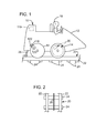
- FIG. 1 is a diagram showing one vehicle disposed on a portion of a path and wherein the vehicle includes a vehicle control system in accordance with one embodiment of the present invention
- FIG. 2 is a diagram showing a top view of a portion of the path of FIG. 1 ;
- FIG. 3 is a block diagram showing details of the vehicle control system of FIG. 1 ;
- FIG. 4 is a flow diagram showing an embodiment of a position control correction module
- FIG. 5 is a schematic diagram showing an amusement ride control system
- FIG. 6 is a flow chart describing a step-wise method in accordance with an embodiment of the present invention.
- One embodiment of the present invention concerns a control system and method for controlling a plurality of vehicles on a fixed path.
- One particular embodiment of the system includes a position control and correction module for correcting spacing between vehicles.
- one vehicle 10 out of a plurality of vehicles of a ride system, is shown with a body 12 , wheels 14 along with a guest 18 seated therein.
- the vehicle 10 is disposed on a path such as a track 20 which includes rails 22 that are supported by cross beams 24 .
- a bus bar or energizing rail 26 provides electrical energy from an electrical generator (described below) to the vehicle 10 through means of an electrode 28 .
- a disc brake 30 is shown mounted to a wheel 14 .
- a distance/speed sensor 116 may comprise a magnet 120 and a magnetic field or optical sensor 122 , which together function in a known manner to provide electrical pulses to a processor (not shown), which correspond to a distance traveled by wheel 14 .
- a processor, memory, timer, distance and a driving and stopping system (each to be discussed further with reference to FIG. 3 ) may be located within compartment 119 .
- the control system 300 comprises a processor 310 , a memory 312 , a timer 314 , a distance/speed sensor 316 and a vehicle driving and stopping system 318 .
- the processor 310 may be any suitable processor such as a programmable logic controller.
- the memory 312 may be any suitable type including but not limited to RAM, ROM, EPROM, and flash.
- the memory 312 may store a program for the processor 310 and store a look up table for a predicted range of locations given a duration that a vehicle is traveling along the track.
- the memory may also be configured to store wheel diameter measurement, horizontal wheel slip measurements and vehicle spacing measurement, e.g., how far each vehicle is from a corresponding vehicle at any particular time.
- the timer 314 provides a timing function that may be used by the processor 310 to time an actual duration that the vehicle is traveling along the track.
- the distance/speed sensor 316 may comprise a magnet and a magnetic field or optical sensor which together function in a known manner to provide electrical pulses to the processor 310 which correspond to a distance traveled by the wheel.
- other sensors such as a multi-turn encoder may be employed.
- the pulses may be counted or directly measured by the processor 310 to determine a distance and, therefrom, a location of the vehicle along the track.
- the vehicle driving and stopping system 318 may be interconnected with a drive motor 334 including a motor controller (not shown) and a brake 332 such as the disc brake 30 ( FIG. 1 ).
- the drive motor 334 may be connected to drive one or more of the wheels 14 ( FIG. 1 ) via velocity commands generated by the processor 310 and sent to the motor controller in a known manner. It will be understood for purposes herein that the greater the magnitude of the velocity command the greater the velocity of the vehicle.
- the processor 310 is configured, via any suitable means such as software or firmware, to receive an initial signal from a start indicator 324 that the vehicle has started traveling along the track and thereafter, to continuously, or at regular intervals, calculate an actual location for the vehicle along the track.
- transponders may be located along the track and a sensor may be provided for ascertaining an actual location for the vehicle.
- the calculated actual location may be used by the processor 310 to control, via the vehicle driving and stopping system 318 , the distance between a plurality of vehicles so that vehicles maintain a predetermined spacing from one another.
- position errors may accumulate during operation because of, e.g., vehicle wheel wear or wheel slippage. For example, as the vehicle increases in age, tires may begin to wear and become smaller, velocity and position errors may accumulate. Also, when vehicles start out or round corners wheel slippage may occur causing further velocity and position errors.
- a position control correction module 330 is provided which may be configured to receive velocity commands from the processor 310 , and return a signal to the processor correcting the velocity commands based on velocity and position errors. Accordingly, the position control correction module 330 advantageously reduces variation in predetermined distance between vehicles to reduce undesirable vehicle contact.
- the position control correction module 330 working with the processor 310 , may be configured to calculate a distance between fixed points, e.g., illuminated by transponders, that are located along a path and identified by additional vehicle position sensors and then compare that value with a known number of wheel revolutions sensed, e.g., by the sensor 116 .
- Current wheel diameter may be calculated and then applied to correct the measured velocity and acceleration.
- the position control correction module 330 may compare a velocity command (V N ), described above, to an actual velocity that the vehicle is traveling along the fixed path. If there is a difference between the velocity of the vehicle expected from the velocity command and the actual velocity of the vehicle, the velocity command may be reduced in magnitude such as to the actual velocity to eliminate the slippage and regain frictional engagement with the fixed path. Thereafter, the velocity commands may be slowly ramped up in magnitude, described below, to thereby retain frictional engagement with the fixed path.
- V N velocity command
- the position control correction module 330 comprises a primary loop 402 including calculator 404 for calculating a smoothed transition speed (see below), a timer 406 , a speed control function 408 , a summation 410 and a summation 412 .
- Secondary loops 414 and 416 are provided for calculating error in velocity and error in position, respectively. More specifically, the secondary loop 414 comprises a calculator for calculating error in velocity (E v ) via F(K v )/T and the secondary loop 416 comprises a calculator for calculating error in position (E p ) via F(K p ). Reference may be had below for an understanding of the terms F(K v ) and F(K p ).
- the secondary loops 414 and 416 contain gain functions 418 and 420 to calculate and weigh the position and velocity errors for the summation 422 .
- a summation 422 combines calculated velocity and position errors (E v ), (E p ) which are, in turn, fed to the summation 410 that subtracts the error values from the velocity at a particular sensed position (V sp ) to achieve a corrected velocity G(v).
- the corrected velocity G(v) and the actual velocity may be provided at 408 and communicated to the processor 310 ( FIG. 3 ) for use in determining whether slippage of the wheel(s) 30 is occurring. If wheel slippage is determined to be occurring by the processor 310 , the processor may reduce the magnitude of the velocity commands to the motor to stop the slippage and then to begin to slowly ramp up the magnitude of the velocity commands to the drive motor as described above.
- the corrected velocity G(v) is thereafter output to the secondary loop 414 to calculate a new error in velocity (E v ) and combined with the output from the timer 406 for use in the secondary loop 416 to calculate a new error in position (E p ). It is also communicated to the processor 310 to determine whether velocity needs to be increased to correct an error in position and thus spacing between vehicles.
- the vehicle velocity commands (V N ) may be applied to an algorithm such as that provided below.
- the acceleration function F(a) of a vehicle may be calculated from the following equation where acceleration is limited by a percentage of the change in velocity to further reduce possible slip during acceleration.
- a function of a gain term (K) for (used in calculating an error in velocity (E v ) and an error in position (E p ) see above) velocity K v and position K p weigh the respective terms so that speed correction is smooth.
- K gain term
- the ride control system 50 comprises a path or track processor 52 which is in circuit with the energizing rail 26 comprising a number of circuit connections (not numbered) and a plurality of vehicle 310 ( FIG. 3 ) each being located with a vehicle 10 ( FIG. 1 ).
- the track processor 52 may communicate via wireless communications with each vehicle processor 310 rather than, e.g., via the energizing rail 26 .
- the track processor 52 may comprise a programmable logic controller and monitors track functions such as mode of the track machine, stopping and starting functions, and control of all track-switching elements via fail-safe signals.
- the track processor 52 and each vehicle processor 310 may communicate to ensure the mode of the track machine is safely controlled for the all vehicles mounted to the track. If there is disagreement of the mode of the track or if the vehicle senses itself out of range for position, velocity, or acceleration parameters or other fault conditions, the vehicle will communicate to the track processor and/or other vehicle processors to cause a stop or other reaction for each vehicle 10 .
- the track processor 52 may also be configured to determine and broadcast an ideal location of each vehicle to each vehicle on the path according to some predetermined plan such as every vehicle is spaced equally along the path. Each vehicle, via each processor 310 , may then synchronize or vary its position along the path by increasing velocity or braking, as described above, to correct its spacing from other vehicles.
- a method of monitoring and controlling location of a plurality of vehicles movable along a path in accordance with another embodiment of the present invention is illustrated generally at 600 in FIG. 6 .
- the method for controlling a plurality of vehicles on a fixed path comprises mounting a processor to each vehicle as shown at 602 and mounting a vehicle sensor device to each vehicle as shown at 604 .
- the method further comprises using each processor and each vehicle sensor device to determine an actual location of each vehicle while each vehicle is moving along the path step 606 and, at step 608 , using a position control correction module to compare each vehicle's actual velocity to each vehicle's velocity commands to determine if wheel slip is occurring and to decrease the magnitude of vehicle velocity commands where wheel slip occurs.
- Technical effects of the herein described systems and methods include correcting a velocity of a vehicle to account for wheel slip. Other technical effects include correcting a vehicle spacing on a track.
Abstract
Description
F(V sp)=Σ[θ−2π,λ π(cos(θ)+1)·[½·(V Nnew −V Nold)]] where:
θ=θ+λ, where λ=F(a)/π
if V Nold ≠V Nnew, θ=π
V N=velocity command
F(a)=a N·[(V N −V actual)/V N]%
where:
V actual =F(V sp)(V N)
a N=acceleration command
F(K v,p)=K v,p ·K v,p ·K wheel ø,
K wheel ø=1−[(actual−measured)/actual)]%
If E v >>ø, θ=π, F(a)=F(a)·K correction
Claims (15)
F(Vsp)=Σ[θ2π,λ π(cos(θ)+1)⊙[½]⊙(V Nnew −V Nold)] where:
F(Vsp)=vehicle transition speeds
θ=θ+λ, where λ=F(a)/π
if V Nold ≠V Nnew, θ=π
V N=velocity command
F(a)=a N⊙[(V N −V actual)/V N]% where:
V actual =F(Vsp)(V N)
a N=acceleration command.
F(Vsp)=Σ[θ2π,λ π(cos(θ)+1)⊙[½]⊙(V Nnew −V Nold)] where:
F(Vsp)=vehicle transition speeds
θ=θ+λ, where λ=F(a)/π
if V Nold ≠V Nnew, θ=π
V N=velocity command
F(a)=a N⊙[(V N −V actual)/V N]% where:
V actual =F(Vsp)(V N)
a N=acceleration command.
F(Vsp)=Σ[θ2π,λ π(cos(θ)+1)⊙[½]⊙(V Nnew −V Nold)] where:
F(Vsp)=vehicle transition speeds
θ=θ+λ, where λ=F(a)/π
if V Nold ≠V Nnew, θ=π
V N=velocity command
F(a)=a N⊙[(V N −V actual)/V N]% where:
V actual =F(Vsp)(V N)
a N=acceleration command.
Priority Applications (14)
| Application Number | Priority Date | Filing Date | Title |
|---|---|---|---|
| US12/344,633 US9308926B2 (en) | 2008-12-29 | 2008-12-29 | Position control system |
| ES09797224.4T ES2662650T3 (en) | 2008-12-29 | 2009-11-30 | Position control system |
| CA2748205A CA2748205C (en) | 2008-12-29 | 2009-11-30 | Position control system |
| KR1020177020789A KR101801012B1 (en) | 2008-12-29 | 2009-11-30 | Position control system |
| JP2011543531A JP2012514446A (en) | 2008-12-29 | 2009-11-30 | Position control system |
| PCT/US2009/066037 WO2010077505A1 (en) | 2008-12-29 | 2009-11-30 | Position control system |
| CN200980153182.3A CN102271985B (en) | 2008-12-29 | 2009-11-30 | Position control system |
| RU2011131873/11A RU2532305C2 (en) | 2008-12-29 | 2009-11-30 | Position control system |
| EP09797224.4A EP2382121B1 (en) | 2008-12-29 | 2009-11-30 | Position control system |
| SG2013097241A SG196780A1 (en) | 2008-12-29 | 2009-11-30 | Position control system |
| SG2011042801A SG172102A1 (en) | 2008-12-29 | 2009-11-30 | Position control system |
| KR1020117017956A KR20110102488A (en) | 2008-12-29 | 2009-11-30 | Position control system |
| MYPI2011003028A MY162390A (en) | 2008-12-29 | 2009-12-30 | Position control system |
| JP2015189170A JP6165814B2 (en) | 2008-12-29 | 2015-09-28 | Vehicle position control method and system |
Applications Claiming Priority (1)
| Application Number | Priority Date | Filing Date | Title |
|---|---|---|---|
| US12/344,633 US9308926B2 (en) | 2008-12-29 | 2008-12-29 | Position control system |
Publications (2)
| Publication Number | Publication Date |
|---|---|
| US20100168940A1 US20100168940A1 (en) | 2010-07-01 |
| US9308926B2 true US9308926B2 (en) | 2016-04-12 |
Family
ID=41697949
Family Applications (1)
| Application Number | Title | Priority Date | Filing Date |
|---|---|---|---|
| US12/344,633 Active 2034-03-13 US9308926B2 (en) | 2008-12-29 | 2008-12-29 | Position control system |
Country Status (11)
| Country | Link |
|---|---|
| US (1) | US9308926B2 (en) |
| EP (1) | EP2382121B1 (en) |
| JP (2) | JP2012514446A (en) |
| KR (2) | KR101801012B1 (en) |
| CN (1) | CN102271985B (en) |
| CA (1) | CA2748205C (en) |
| ES (1) | ES2662650T3 (en) |
| MY (1) | MY162390A (en) |
| RU (1) | RU2532305C2 (en) |
| SG (2) | SG172102A1 (en) |
| WO (1) | WO2010077505A1 (en) |
Cited By (3)
| Publication number | Priority date | Publication date | Assignee | Title |
|---|---|---|---|---|
| KR100324081B1 (en) * | 1993-05-28 | 2002-05-13 | 도날 비. 토빈 | Cutting part coating method |
| US20190002001A1 (en) * | 2015-12-22 | 2019-01-03 | Televic Rail Nv | System and method for providing information to an information system in a vehicle |
| US11203349B2 (en) * | 2016-09-02 | 2021-12-21 | Pioneer Corporation | Velocity calculation apparatus, control method, program and storage medium |
Families Citing this family (13)
| Publication number | Priority date | Publication date | Assignee | Title |
|---|---|---|---|---|
| US8844800B2 (en) * | 2008-03-31 | 2014-09-30 | Google Inc. | Ratings using machine-readable representations |
| US20130278441A1 (en) | 2012-04-24 | 2013-10-24 | Zetta Research and Development, LLC - ForC Series | Vehicle proxying |
| US9205828B1 (en) | 2012-06-29 | 2015-12-08 | Google Inc. | Method and apparatus for determining vehicle location based on motor feedback |
| DE102013205698A1 (en) * | 2013-03-28 | 2014-10-02 | Siemens Aktiengesellschaft | Device for controlling a drive device in a rail vehicle |
| EP2792394B1 (en) * | 2013-04-16 | 2016-07-27 | Jörg Beutler | Interactive speed control |
| US9045151B2 (en) * | 2013-06-18 | 2015-06-02 | Tech4U Dynamics Inc. | Track barcode systems for railroad management |
| CN103318194A (en) * | 2013-07-01 | 2013-09-25 | 中国北车集团大连机车车辆有限公司 | Axle load transfer compensation method of locomotive |
| US9457282B2 (en) * | 2014-05-21 | 2016-10-04 | Universal City Studios Llc | Virtual attraction controller |
| JP6730057B2 (en) * | 2016-03-30 | 2020-07-29 | 株式会社東芝 | Electric vehicle control device |
| US10279823B2 (en) * | 2016-08-08 | 2019-05-07 | General Electric Company | System for controlling or monitoring a vehicle system along a route |
| US10357721B2 (en) * | 2017-06-28 | 2019-07-23 | Disney Enterprises, Inc. | Distributed and autonomous control system for guided-path vehicles |
| CN111086500B (en) * | 2020-03-23 | 2020-07-31 | 盛瑞传动股份有限公司 | Vehicle slip protection method and system and vehicle |
| US20220185346A1 (en) * | 2020-12-16 | 2022-06-16 | Westinghouse Air Brake Technologies Corporation | Monitoring system |
Citations (37)
| Publication number | Priority date | Publication date | Assignee | Title |
|---|---|---|---|---|
| US4498016A (en) * | 1983-08-04 | 1985-02-05 | Caterpillar Tractor Co. | Locomotive governor control |
| JPS63249405A (en) | 1987-04-03 | 1988-10-17 | Fuji Electric Co Ltd | Racing prevention system for running truck |
| US4864306A (en) | 1986-06-23 | 1989-09-05 | Wiita Floyd L | Railway anticollision apparatus and method |
| JPH04251502A (en) | 1991-01-07 | 1992-09-07 | Toyo Electric Mfg Co Ltd | Controller for electric vehicle |
| US5197562A (en) * | 1990-04-28 | 1993-03-30 | Aisin Seiki K.K. | Vehicle cruising control device |
| US5305693A (en) * | 1993-05-26 | 1994-04-26 | The Walt Disney Company | System and method for externally controlled spacing of self propelled vehicles along a rail |
| JPH07170603A (en) | 1993-12-16 | 1995-07-04 | Shinko Electric Co Ltd | Speed correcting method |
| US5473225A (en) * | 1992-04-21 | 1995-12-05 | Kabushiki Kaisha Toshiba | Electric motor vehicle control apparatus and method for reducing the occurrence of wheel slip |
| US5495251A (en) * | 1993-02-20 | 1996-02-27 | Lucas Industries Public Limited Company | Method of and apparatus for cruise control |
| US5533695A (en) | 1994-08-19 | 1996-07-09 | Harmon Industries, Inc. | Incremental train control system |
| DE19509696A1 (en) * | 1995-03-08 | 1996-09-12 | Siemens Ag | Train safety spacing system |
| CN1134559A (en) | 1994-12-28 | 1996-10-30 | 株式会社日立制作所 | Controller having fail safe function, automatic train controller, and system using the same |
| US5595121A (en) * | 1994-04-15 | 1997-01-21 | The Walt Disney Company | Amusement ride and self-propelled vehicle therefor |
| JPH09140009A (en) | 1995-11-14 | 1997-05-27 | Shinko Electric Co Ltd | Controller of driving wheel |
| US5689422A (en) * | 1994-04-18 | 1997-11-18 | Technion Research And Development Foundation Ltd. | Converter for cruise control system |
| US6148269A (en) * | 1998-07-20 | 2000-11-14 | General Electric Company | Wheel diameter calibration system for vehicle slip/slide control |
| US6285944B1 (en) * | 1998-06-18 | 2001-09-04 | Nissan Motor Co., Ltd. | Apparatus and method for performing automatic control over velocity of automotive vehicle |
| US6295487B1 (en) * | 1998-07-21 | 2001-09-25 | Tokyo R & D Co., Ltd. | Hybrid vehicle and method of controlling the travel of the vehicle |
| US6420996B1 (en) * | 2001-08-08 | 2002-07-16 | Ford Global Technologies, Inc. | Integrated radar and active transponder collision prediction system |
| US6526346B2 (en) * | 2000-05-16 | 2003-02-25 | Nissan Motor Co., Ltd. | System and method for controlling vehicle velocity and inter-vehicle distance |
| US6532411B2 (en) * | 2001-02-07 | 2003-03-11 | Hitachi, Ltd. | Brake booster control device and method of controlling the same |
| US6587763B2 (en) | 2001-11-12 | 2003-07-01 | East Japan Railway Company | Train control system and method therefor |
| US6600987B2 (en) * | 2000-06-29 | 2003-07-29 | Unisia Jecs Corporation | Apparatus and method for determining a road-wheel vibration of automotive vehicle, and apparatus and method for anti-skid control using the same |
| DE10209378A1 (en) | 2002-03-02 | 2003-09-18 | Kiepe Elek K Gmbh & Co Kg | Detecting and minimizing centrifugal and sliding processes of short-range electric railway vehicle involves locking control loop if maximum revolution rate difference exceeded and nulling |
| US6666411B1 (en) | 2002-05-31 | 2003-12-23 | Alcatel | Communications-based vehicle control system and method |
| US6691014B2 (en) * | 2001-03-14 | 2004-02-10 | Wabco Gmbh & Co. Ohg | Method and device for controlling the cornering speed of a vehicle |
| WO2004024531A1 (en) | 2002-09-13 | 2004-03-25 | Bombardier Transportation Gmbh | Vehicle on-board diagnostic system |
| US20040181320A1 (en) | 2002-05-31 | 2004-09-16 | Kane Mark Edward | Method and system for compensating for wheel wear on a train |
| US6853902B2 (en) * | 2000-02-02 | 2005-02-08 | Jaguar Cars Limited | Motor vehicle dynamic stability control |
| US7084602B2 (en) * | 2004-02-17 | 2006-08-01 | Railpower Technologies Corp. | Predicting wheel slip and skid in a locomotive |
| US7182298B2 (en) | 2002-10-30 | 2007-02-27 | Duerr Systems Gmbh | Track-guided transport system and method for controlling cars of a track-guided transport system |
| US7286934B2 (en) * | 2001-10-22 | 2007-10-23 | Cascade Engineering, Inc. | Individual transport control and communication system |
| US7451034B2 (en) * | 2006-03-10 | 2008-11-11 | Ford Global Technologies, Llc | Traction control using dynamic tire friction potential |
| JP2008289237A (en) | 2007-05-16 | 2008-11-27 | Railway Technical Res Inst | Motor controller and readhesion control method |
| WO2009032382A2 (en) | 2007-08-30 | 2009-03-12 | General Electric Company | Virtual omnimover |
| US20090114114A1 (en) * | 2007-11-05 | 2009-05-07 | Disney Enterprises, Inc. | Magnetic pacer for controlling speeds in amusement park rides |
| US7739023B2 (en) * | 2005-12-17 | 2010-06-15 | Hyundai Motor Company | Adaptive cruise control system and method for vehicle |
Family Cites Families (8)
| Publication number | Priority date | Publication date | Assignee | Title |
|---|---|---|---|---|
| GB2192160B (en) * | 1986-06-30 | 1990-04-25 | Aisin Warner | Four-wheel drive vehicle having antislip apparatus |
| JPH0648305U (en) * | 1993-10-20 | 1994-06-28 | 株式会社ダイフク | Self-propelled vehicle speed control device |
| JP3525397B2 (en) * | 1995-01-19 | 2004-05-10 | 富士電機システムズ株式会社 | Control device for traveling vehicles |
| JP3792372B2 (en) * | 1997-10-08 | 2006-07-05 | 住友ナコ マテリアル ハンドリング株式会社 | Reach forklift |
| JP2001352611A (en) * | 2000-06-06 | 2001-12-21 | Hitachi Ltd | Electric car control device and controlling method and electric car utilizing them |
| JP2006117808A (en) * | 2004-10-22 | 2006-05-11 | Nippon Steel Corp | Speed controlling method for coke conveying apparatus |
| JP4569266B2 (en) * | 2004-11-09 | 2010-10-27 | 日産自動車株式会社 | Vehicle motor traction control device |
| US7705972B2 (en) * | 2006-06-20 | 2010-04-27 | Virginia Tech Intellectual Properties, Inc. | Doppler sensor for the derivation of torsional slip, friction and related parameters |
-
2008
- 2008-12-29 US US12/344,633 patent/US9308926B2/en active Active
-
2009
- 2009-11-30 SG SG2011042801A patent/SG172102A1/en unknown
- 2009-11-30 WO PCT/US2009/066037 patent/WO2010077505A1/en active Application Filing
- 2009-11-30 SG SG2013097241A patent/SG196780A1/en unknown
- 2009-11-30 RU RU2011131873/11A patent/RU2532305C2/en active
- 2009-11-30 CA CA2748205A patent/CA2748205C/en active Active
- 2009-11-30 JP JP2011543531A patent/JP2012514446A/en active Pending
- 2009-11-30 ES ES09797224.4T patent/ES2662650T3/en active Active
- 2009-11-30 KR KR1020177020789A patent/KR101801012B1/en active IP Right Grant
- 2009-11-30 CN CN200980153182.3A patent/CN102271985B/en active Active
- 2009-11-30 EP EP09797224.4A patent/EP2382121B1/en active Active
- 2009-11-30 KR KR1020117017956A patent/KR20110102488A/en active Application Filing
- 2009-12-30 MY MYPI2011003028A patent/MY162390A/en unknown
-
2015
- 2015-09-28 JP JP2015189170A patent/JP6165814B2/en active Active
Patent Citations (39)
| Publication number | Priority date | Publication date | Assignee | Title |
|---|---|---|---|---|
| US4498016A (en) * | 1983-08-04 | 1985-02-05 | Caterpillar Tractor Co. | Locomotive governor control |
| US4864306A (en) | 1986-06-23 | 1989-09-05 | Wiita Floyd L | Railway anticollision apparatus and method |
| JPS63249405A (en) | 1987-04-03 | 1988-10-17 | Fuji Electric Co Ltd | Racing prevention system for running truck |
| US5197562A (en) * | 1990-04-28 | 1993-03-30 | Aisin Seiki K.K. | Vehicle cruising control device |
| JPH04251502A (en) | 1991-01-07 | 1992-09-07 | Toyo Electric Mfg Co Ltd | Controller for electric vehicle |
| US5473225A (en) * | 1992-04-21 | 1995-12-05 | Kabushiki Kaisha Toshiba | Electric motor vehicle control apparatus and method for reducing the occurrence of wheel slip |
| US5495251A (en) * | 1993-02-20 | 1996-02-27 | Lucas Industries Public Limited Company | Method of and apparatus for cruise control |
| US5305693A (en) * | 1993-05-26 | 1994-04-26 | The Walt Disney Company | System and method for externally controlled spacing of self propelled vehicles along a rail |
| JPH07170603A (en) | 1993-12-16 | 1995-07-04 | Shinko Electric Co Ltd | Speed correcting method |
| US5595121A (en) * | 1994-04-15 | 1997-01-21 | The Walt Disney Company | Amusement ride and self-propelled vehicle therefor |
| US5689422A (en) * | 1994-04-18 | 1997-11-18 | Technion Research And Development Foundation Ltd. | Converter for cruise control system |
| US5533695A (en) | 1994-08-19 | 1996-07-09 | Harmon Industries, Inc. | Incremental train control system |
| EP1302382A2 (en) * | 1994-12-28 | 2003-04-16 | Hitachi, Ltd. | Controller having a fail safe function, automatic train controller, and system using the same |
| CN1134559A (en) | 1994-12-28 | 1996-10-30 | 株式会社日立制作所 | Controller having fail safe function, automatic train controller, and system using the same |
| DE19509696A1 (en) * | 1995-03-08 | 1996-09-12 | Siemens Ag | Train safety spacing system |
| CN1137993A (en) | 1995-03-08 | 1996-12-18 | 西门子公司 | Method for establishing mutual contact within train and device for implementing the method |
| JPH09140009A (en) | 1995-11-14 | 1997-05-27 | Shinko Electric Co Ltd | Controller of driving wheel |
| US6285944B1 (en) * | 1998-06-18 | 2001-09-04 | Nissan Motor Co., Ltd. | Apparatus and method for performing automatic control over velocity of automotive vehicle |
| US6148269A (en) * | 1998-07-20 | 2000-11-14 | General Electric Company | Wheel diameter calibration system for vehicle slip/slide control |
| US6295487B1 (en) * | 1998-07-21 | 2001-09-25 | Tokyo R & D Co., Ltd. | Hybrid vehicle and method of controlling the travel of the vehicle |
| US6853902B2 (en) * | 2000-02-02 | 2005-02-08 | Jaguar Cars Limited | Motor vehicle dynamic stability control |
| US6526346B2 (en) * | 2000-05-16 | 2003-02-25 | Nissan Motor Co., Ltd. | System and method for controlling vehicle velocity and inter-vehicle distance |
| US6600987B2 (en) * | 2000-06-29 | 2003-07-29 | Unisia Jecs Corporation | Apparatus and method for determining a road-wheel vibration of automotive vehicle, and apparatus and method for anti-skid control using the same |
| US6532411B2 (en) * | 2001-02-07 | 2003-03-11 | Hitachi, Ltd. | Brake booster control device and method of controlling the same |
| US6691014B2 (en) * | 2001-03-14 | 2004-02-10 | Wabco Gmbh & Co. Ohg | Method and device for controlling the cornering speed of a vehicle |
| US6420996B1 (en) * | 2001-08-08 | 2002-07-16 | Ford Global Technologies, Inc. | Integrated radar and active transponder collision prediction system |
| US7286934B2 (en) * | 2001-10-22 | 2007-10-23 | Cascade Engineering, Inc. | Individual transport control and communication system |
| US6587763B2 (en) | 2001-11-12 | 2003-07-01 | East Japan Railway Company | Train control system and method therefor |
| DE10209378A1 (en) | 2002-03-02 | 2003-09-18 | Kiepe Elek K Gmbh & Co Kg | Detecting and minimizing centrifugal and sliding processes of short-range electric railway vehicle involves locking control loop if maximum revolution rate difference exceeded and nulling |
| US6666411B1 (en) | 2002-05-31 | 2003-12-23 | Alcatel | Communications-based vehicle control system and method |
| US20040181320A1 (en) | 2002-05-31 | 2004-09-16 | Kane Mark Edward | Method and system for compensating for wheel wear on a train |
| WO2004024531A1 (en) | 2002-09-13 | 2004-03-25 | Bombardier Transportation Gmbh | Vehicle on-board diagnostic system |
| US7182298B2 (en) | 2002-10-30 | 2007-02-27 | Duerr Systems Gmbh | Track-guided transport system and method for controlling cars of a track-guided transport system |
| US7084602B2 (en) * | 2004-02-17 | 2006-08-01 | Railpower Technologies Corp. | Predicting wheel slip and skid in a locomotive |
| US7739023B2 (en) * | 2005-12-17 | 2010-06-15 | Hyundai Motor Company | Adaptive cruise control system and method for vehicle |
| US7451034B2 (en) * | 2006-03-10 | 2008-11-11 | Ford Global Technologies, Llc | Traction control using dynamic tire friction potential |
| JP2008289237A (en) | 2007-05-16 | 2008-11-27 | Railway Technical Res Inst | Motor controller and readhesion control method |
| WO2009032382A2 (en) | 2007-08-30 | 2009-03-12 | General Electric Company | Virtual omnimover |
| US20090114114A1 (en) * | 2007-11-05 | 2009-05-07 | Disney Enterprises, Inc. | Magnetic pacer for controlling speeds in amusement park rides |
Non-Patent Citations (1)
| Title |
|---|
| Office Action for Japanese Patent Application No. 2011543531 issued Nov. 25, 2013. |
Cited By (4)
| Publication number | Priority date | Publication date | Assignee | Title |
|---|---|---|---|---|
| KR100324081B1 (en) * | 1993-05-28 | 2002-05-13 | 도날 비. 토빈 | Cutting part coating method |
| US20190002001A1 (en) * | 2015-12-22 | 2019-01-03 | Televic Rail Nv | System and method for providing information to an information system in a vehicle |
| US10994759B2 (en) * | 2015-12-22 | 2021-05-04 | Televic Rail Nv | System and method for providing information to an information system in a vehicle |
| US11203349B2 (en) * | 2016-09-02 | 2021-12-21 | Pioneer Corporation | Velocity calculation apparatus, control method, program and storage medium |
Also Published As
| Publication number | Publication date |
|---|---|
| CA2748205A1 (en) | 2010-07-08 |
| EP2382121A1 (en) | 2011-11-02 |
| WO2010077505A1 (en) | 2010-07-08 |
| SG172102A1 (en) | 2011-07-28 |
| KR101801012B1 (en) | 2017-11-23 |
| SG196780A1 (en) | 2014-02-13 |
| RU2532305C2 (en) | 2014-11-10 |
| EP2382121B1 (en) | 2018-01-10 |
| JP6165814B2 (en) | 2017-07-19 |
| KR20110102488A (en) | 2011-09-16 |
| JP2012514446A (en) | 2012-06-21 |
| MY162390A (en) | 2017-06-15 |
| RU2011131873A (en) | 2013-02-10 |
| JP2016042784A (en) | 2016-03-31 |
| KR20170089960A (en) | 2017-08-04 |
| US20100168940A1 (en) | 2010-07-01 |
| ES2662650T3 (en) | 2018-04-09 |
| CN102271985A (en) | 2011-12-07 |
| CN102271985B (en) | 2016-08-10 |
| CA2748205C (en) | 2017-05-23 |
Similar Documents
| Publication | Publication Date | Title |
|---|---|---|
| US9308926B2 (en) | Position control system | |
| US10183685B2 (en) | Virtual omnimover | |
| US20100324776A1 (en) | Device for Measuring the Movement of a Self-Guided Vehicle | |
| KR101157756B1 (en) | Device for measuring the movement of a self-guiding vehicle | |
| CN111032459B (en) | Method and device for determining a braking-related actual value of a rail vehicle | |
| CN107206913A (en) | Train controller, Train control method and program | |
| JP6877306B2 (en) | Train position detection system, automatic train control system, train operation support system and train obstacle detection system | |
| CN110997447B (en) | Method and device for monitoring a drive system of a rail vehicle | |
| KR101577122B1 (en) | Systems and Method for Stopping Train on Stop Position | |
| CN114620096B (en) | Processing method after wheel diameter calibration failure, vehicle-mounted controller, train and medium | |
| EP4194313A1 (en) | On-board detection device for a railway vehicle, railway vehicle comprising such device and associated railway system | |
| JPH10315973A (en) | Automatic train operation device | |
| JP7284290B2 (en) | Train control system and fixed position stop control method | |
| WO2022113177A1 (en) | On-board control device and acceleration sensor diagnostic method | |
| KR101049175B1 (en) | Train control system using neural network | |
| KR101057976B1 (en) | Train travel distance correction and train control method using the same | |
| WO2008076627A1 (en) | A system and method for measuring the wheelbase of a railcar | |
| JP2023141304A (en) | Train operation control device, train operation control method, and program | |
| JP3632008B2 (en) | Autonomous driving vehicle | |
| KR101344755B1 (en) | Apparatus and method for measuring velocity by using kalman filter | |
| JPH023364B2 (en) | ||
| JPH03103009A (en) | Stop control method for track car travelling in band system | |
| JP2009090855A (en) | Train operation control system |
Legal Events
| Date | Code | Title | Description |
|---|---|---|---|
| AS | Assignment |
Owner name: UNIVERSAL CITY STUDIOS LLLP,CALIFORNIA Free format text: ASSIGNMENT OF ASSIGNORS INTEREST;ASSIGNOR:KING, STEVEN MORRIS;REEL/FRAME:022032/0884 Effective date: 20081226 Owner name: UNIVERSAL CITY STUDIOS LLLP, CALIFORNIA Free format text: ASSIGNMENT OF ASSIGNORS INTEREST;ASSIGNOR:KING, STEVEN MORRIS;REEL/FRAME:022032/0884 Effective date: 20081226 |
|
| AS | Assignment |
Owner name: UNIVERSAL CITY STUDIOS LLC, CALIFORNIA Free format text: MERGER;ASSIGNOR:UNIVERSAL CITY STUDIOS LLLP;REEL/FRAME:025866/0068 Effective date: 20110121 |
|
| STCF | Information on status: patent grant |
Free format text: PATENTED CASE |
|
| MAFP | Maintenance fee payment |
Free format text: PAYMENT OF MAINTENANCE FEE, 4TH YEAR, LARGE ENTITY (ORIGINAL EVENT CODE: M1551); ENTITY STATUS OF PATENT OWNER: LARGE ENTITY Year of fee payment: 4 |
|
| MAFP | Maintenance fee payment |
Free format text: PAYMENT OF MAINTENANCE FEE, 8TH YEAR, LARGE ENTITY (ORIGINAL EVENT CODE: M1552); ENTITY STATUS OF PATENT OWNER: LARGE ENTITY Year of fee payment: 8 |