US9324170B2 - Creating a blended image - Google Patents
Creating a blended image Download PDFInfo
- Publication number
- US9324170B2 US9324170B2 US14/239,511 US201114239511A US9324170B2 US 9324170 B2 US9324170 B2 US 9324170B2 US 201114239511 A US201114239511 A US 201114239511A US 9324170 B2 US9324170 B2 US 9324170B2
- Authority
- US
- United States
- Prior art keywords
- pixel
- image frame
- image
- color saturation
- edge
- Prior art date
- Legal status (The legal status is an assumption and is not a legal conclusion. Google has not performed a legal analysis and makes no representation as to the accuracy of the status listed.)
- Active, expires
Links
- 238000002156 mixing Methods 0.000 claims abstract description 74
- 238000000034 method Methods 0.000 claims description 32
- 238000012545 processing Methods 0.000 claims description 11
- 239000000203 mixture Substances 0.000 claims description 2
- 238000010586 diagram Methods 0.000 description 14
- 230000006870 function Effects 0.000 description 7
- 238000009499 grossing Methods 0.000 description 6
- 230000002093 peripheral effect Effects 0.000 description 5
- 230000007704 transition Effects 0.000 description 5
- 230000011218 segmentation Effects 0.000 description 4
- 230000015572 biosynthetic process Effects 0.000 description 3
- 238000006243 chemical reaction Methods 0.000 description 3
- 238000003708 edge detection Methods 0.000 description 3
- 238000005259 measurement Methods 0.000 description 3
- 238000012986 modification Methods 0.000 description 3
- 230000004048 modification Effects 0.000 description 3
- 230000000877 morphologic effect Effects 0.000 description 3
- 238000003786 synthesis reaction Methods 0.000 description 3
- 238000012935 Averaging Methods 0.000 description 2
- 230000003247 decreasing effect Effects 0.000 description 2
- 230000010339 dilation Effects 0.000 description 2
- 239000000463 material Substances 0.000 description 2
- 230000002194 synthesizing effect Effects 0.000 description 2
- 238000007792 addition Methods 0.000 description 1
- 230000009286 beneficial effect Effects 0.000 description 1
- 238000012217 deletion Methods 0.000 description 1
- 230000037430 deletion Effects 0.000 description 1
- 238000001514 detection method Methods 0.000 description 1
- 125000001475 halogen functional group Chemical group 0.000 description 1
- 230000001172 regenerating effect Effects 0.000 description 1
- 238000012546 transfer Methods 0.000 description 1
- 230000000007 visual effect Effects 0.000 description 1
Images


Classifications
-
- G—PHYSICS
- G06—COMPUTING; CALCULATING OR COUNTING
- G06T—IMAGE DATA PROCESSING OR GENERATION, IN GENERAL
- G06T11/00—2D [Two Dimensional] image generation
- G06T11/60—Editing figures and text; Combining figures or text
-
- G—PHYSICS
- G06—COMPUTING; CALCULATING OR COUNTING
- G06T—IMAGE DATA PROCESSING OR GENERATION, IN GENERAL
- G06T15/00—3D [Three Dimensional] image rendering
- G06T15/50—Lighting effects
- G06T15/503—Blending, e.g. for anti-aliasing
-
- G—PHYSICS
- G06—COMPUTING; CALCULATING OR COUNTING
- G06T—IMAGE DATA PROCESSING OR GENERATION, IN GENERAL
- G06T11/00—2D [Two Dimensional] image generation
-
- G—PHYSICS
- G06—COMPUTING; CALCULATING OR COUNTING
- G06T—IMAGE DATA PROCESSING OR GENERATION, IN GENERAL
- G06T11/00—2D [Two Dimensional] image generation
- G06T11/001—Texturing; Colouring; Generation of texture or colour
Definitions
- image processing As individuals and organizations increase their consumption of digital visual media, the demand for increasingly complex image processing products continues to grow.
- One field in which image processing has been particularly active is that of image blending.
- image blending two separately rendered digital images are combined into and displayed as single digital image. This functionality may be useful, for example, in a video conferencing application that combines a first video image of participants from a remote site with a second video image of presentation materials to create a single video image depicting the participants at the remote site in the background and the shared presentation materials in the foreground.
- the foreground image When combining a background image with a foreground image to create a blended image, it may be desirable to make certain portions of the foreground image appear relatively more transparent or opaque with respect to other portions of the foreground image. For example, it may be desirable to make the most important features of the foreground image more opaque to convey a clear picture of the foreground, while making less-important areas of the foreground image more transparent to show the background image.
- FIG. 1 is a block diagram of an illustrative image blending system according to one example of the principles described herein.
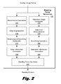
- FIG. 2 is a block diagram of an illustrative blending factor generation module, according to one example of the principles described herein.
- FIG. 3 is a block diagram of an illustrative image blending device, according to one example of the principles described herein.
- FIG. 4 is a block diagram of an illustrative method for creating a blended image, according to one example of the principles described herein.
- FIG. 5 is a block diagram of an illustrative method for creating a blended image, according to one example of the principles described herein.
- FIG. 6 is a block diagram of an illustrative method for creating a blended image, according to one example of the principles described herein.
- FIG. 7 is a block diagram of an illustrative computing device for implementing an illustrative image blending system, according to one example of the principles described herein.
- the foreground image when combining a background image with a foreground image to create a blended image, it may be desirable to make certain portions of the foreground image appear relatively more transparent or opaque with respect to other portions of the foreground image. For example, it may be aesthetically preferable to make the most important features of the foreground image more opaque to convey a clear picture of the foreground, while making less-important areas of the foreground image more transparent to show the background image.
- the present specification discloses methods and systems of combining two or more images to create a blended image.
- the present specification discloses methods which include at least: a) receiving an overlay image frame in a device implemented by electronic circuitry, the overlay image frame having multiple pixels; and b) determining a blending factor with the device for each pixel in the overlay image frame based on the color saturation surrounding that pixel, in which an amount by which the pixel contributes to a blended image of the overlay image frame with an underlying image frame is based on the blending factor.
- the specification further discloses examples of methods for creating a blended image which include at least: a) receiving an overlay image frame and an underlying image frame in a device implemented by electronic circuitry, each of the image frames having multiple pixels; b) for each pixel in the overlay image frame, determining with the device a blending factor based on edge information associated with an area surrounding the pixel and saturation information associated with the area surrounding the pixel; and c) combining the overlay image frame and the underlying image frame into a blended image frame with the device such that an opacity of each pixel of the overlay image frame in the blended image is determined by the blending factor for that pixel.
- the specification also discloses examples of image processing systems that include at least electronic circuitry communicatively coupled to a first image source and a second image source such that the electronic circuitry blends an image frame received from the first image source with an image frame received from the second image source by: a) for each pixel in the image frame received from the first image source, determining a blending factor based on edge information for an area surrounding the pixel and color saturation information for the area surrounding the pixel; b) creating a version of the image frame received from the first image source by altering each pixel in the image frame received from the first image source based on the blending factor for that pixel; and c) combining the version of the image frame received from the first image source with the image frame received from the second image source.
- image frame refers to a two-dimensional image or a digital representation of a two-dimensional image.
- overlay image frame refers to an image frame that, when combined with another image frame in a blended image frame, appears to be above the other image frame.
- underlying image frame refers to an image frame that, when combined with another image frame in a blended image frame, appears to be below the other image frame.
- the term “contribute” in the context of a first source pixel's contribution to a blended image refers to the extent to which the appearance or characteristic of a corresponding pixel in the blended image is attributable to the appearance or characteristic of the first source pixel, as opposed to any other source pixel.
- FIG. 1 is a block diagram of an illustrative system ( 100 ) for creating a blended image, according to one example of the principles of the present specification.
- the system ( 100 ) includes an image blending device ( 105 ) communicatively coupled to an overlay image source ( 110 ) and an underlying image source ( 115 ).
- the image blending device ( 105 ) combines an overlay image frame received from the overlay image source ( 110 ) with an underlying image frame received from the underlying image source ( 115 ) to create a blended output image frame.
- the overlay image frame and the underlying image source frame may be individual frames from a sequence of frames that make up an overlay video and an underlying video, respectively, in a blended video stream.
- the overlay image frame and the underlying image source frame may be single, still image frames independent of any video.
- the blended output image produced by the image blending device ( 105 ) may be a combination of the overlay image frame with the underlying image frame such that in the displayed blended output image, features of the overlay image frame appear to be above features in the underlying image frame.
- the opacity of certain pixels from the overlay image frame may be adjusted in the blended output image frame.
- the degree to which features of the underlying image frame are manifest in the blended output image frame may be determined at the blending stage of the image blending device ( 105 ).
- a pixel from the overlay image frame (“the overlay pixel”) may be combined with a corresponding pixel from the underlying image frame (“the underlying pixel”) to produce a pixel in the blended output image frame (“the blended pixel”).
- the contribution of the overlay pixel to the blended pixel may be adjusted in proportion to a determined importance of the overlay pixel to the overlay image frame.
- the contribution of the overlay pixel to the blended pixel may be increased relative to the underlying pixel such that the portion of the overlay image frame corresponding to the overlay pixel appears more opaque in the blended image frame.
- the contribution of the overlay pixel to the blended pixel may be decreased relative to the underlying pixel such that the portion of the overlay image frame corresponding to the overlay pixel appears more transparent in the blended image frame.
- the image blending device ( 105 ) may include electronic circuitry, such as a processor, an application-specific integrated circuit, a field programmable gate array, or the like, that implements a blending factor generation module ( 120 ) and a blending module ( 125 ).
- the blending factor generation module ( 120 ) determines the relative importance of each pixel in the overlay image frame and generates a blending factor for that pixel.
- the blending factor for each pixel in the overlay image frame is used by the blending module ( 125 ) to determine the contribution of that pixel (e.g., its relative opacity or transparency) to the blended output image frame. That is, the blending module ( 125 ) combines the overlay image frame with the underlying image frame according to the blending factors generated for each pixel in the overlay image frame.
- FIG. 2 is a block diagram of one example of a blending factor generation module ( 120 ), consistent with the above description of FIG. 1 .
- the blending factor generation module ( 120 ) produces a blending factor for each pixel in the overlay image frame based on edge and color saturation information extrapolated from the overlay image frame.
- the blending factor generation module ( 120 ) may receive a copy of the overlay image frame from the overlay image source ( 110 ) and analyze the overlay image frame for edge and color saturation data, which may then be synthesized into the blending factor provided to the blending module ( 125 , FIG. 1 ).
- the overlay image frame is passed through parallel image processing pipelines to extract the edge information and color saturation information used to create the blending factors. It should be understood, however, that in other examples the image processing for both edge and color saturation information may not be performed in parallel. In still other examples, only one of the edge information or the color saturation information may be extracted from the overlay image frame to produce the blending factors. Furthermore, other types of information may be extracted from the overlay image frame and be used together with the edge and/or color saturation information to determine the blending factors. Examples of this type of additional information include, but are not limited to pixel hue information, pixel brightness information, image feature size information, image feature hue information, image feature brightness information, and the like.
- the edge information pipeline may include a monochrome conversion module ( 205 ) for converting the overlay image frame to a monochrome image. This conversion may facilitate the detection of image feature edges within the overlay image frame.
- An edge segmentation module ( 210 ) may build a binary edge map that indicates, for each pixel in the monochrome image, whether that pixel is near an image feature edge. The binary edge map may be generated using a simple edge segmentation function that examines each pixel in the monochrome image and compares that pixel to one or more selected neighboring pixels.
- the edge value on the binary edge map for the pixel being evaluated may be set to 0, indicating that the evaluated pixel is not located on an edge. In all other cases, the edge value on the binary edge map for the pixel being evaluated may be set to 1, indicating that the evaluated pixel is located on an edge.
- a morphological and smoothing operations module ( 215 ) in the edge information pipeline may perform morphological and smoothing operations on the edge map generated by the edge segmentation module ( 210 ). For example, a dilation or closing operation may be applied to the binary edge map to thicken lines and remove possible holes inside edge regions. Also, a low-pass filter may be applied to the binary edge map to create smooth transition regions between flat and edge regions indicated on the binary edge map.
- the low-pass filter may be an averaging, a Gaussian, or any other type of filter that may suit a particular application of the principles described herein.
- the size of the filter chosen empirically, may control the width of the transition regions. For example, a larger filter size may create smoother transitions, but may also be computationally more expensive.
- An edge information generation module ( 220 ) may produce edge information from the processed binary edge map for use in synthesizing a blending factor for each pixel of the overlay image frame.
- the edge-adaptive factor may be generated using a lookup table.
- the edge-adaptive factor may be separately computed for each pixel.
- the edge-adaptive factors for the pixels may then be provided to the blending factor synthesis module ( 225 ).
- a saturation image conversion module ( 230 ) may convert the overlay image frame into a color saturation image frame, such as the color saturation component used in a Hue-Saturation-Value (HSV) color space image.
- a saturation measurement module ( 235 ) may then determine the color saturation value of each pixel in the color saturation image frame. For example, the saturation measurement module ( 235 ) may store the color saturation value of each pixel in a map or other data structure.
- a smoothing operations module ( 240 ) may apply a low-pass filter to the color saturation values of produced by the color saturation measurement module ( 235 ), similar to the low-pass filter described with respect to the morphological/smoothing operations module ( 215 ) of the edge information pipeline.
- a color saturation information generation module ( 245 ) may produce a color saturation-adaptive factor from the processed color saturation values for use in synthesizing a blending factor for each pixel of the overlay image frame.
- the color saturation-adaptive factor may be generated for each pixel using a lookup table.
- the color saturation-adaptive factor may be separately computed for each pixel.
- the color saturation-adaptive factors for the pixels may then be provided to the blending factor synthesis module ( 225 ).
- the blending factor synthesis module ( 225 ) may synthesize a blending factor for each pixel of the overlay image frame from the received edge-adaptive factor and color saturation-adaptive factor corresponding to that particular pixel.
- the greater of the edge-adaptive factor and the color saturation-adaptive factor may be set as the blending factor.
- a weighted combination of the edge-adaptive factor and the color saturation-adaptive factor may be set as the blending factor.
- FIG. 3 is a block diagram of one example of a blending module ( 125 ) consistent with the principles described in relation to FIG. 1 .
- the blending module ( 125 ) receives as input the original overlay image frame, the original underlying image frame, and the blending factors produced by the blending factor generation module ( 120 ) for each pixel of the overlay image frame. Based on the blending factor for each pixel of the overlay image frame, a pixel-specific opacity adjustment module ( 305 ) may adjust the pixel to increase or decrease the opacity of that pixel in the output blended image frame.
- the opacity of a pixel may be increased by increasing the saturation of that pixel, and the transparency of the pixel may increased by decreasing the saturation of that pixel. Additionally or alternatively, opacity may be added to a region of one or more pixels by adding random noise or a pattern with a small magnitude which is lower than the threshold used in the edge segmentation to the pixels in the region.
- An adder circuit ( 310 ) may sum the underlying image frame with the adjusted overlay image frame to produce the output blended image frame.
- FIG. 4 is a flowchart diagram of an illustrative method ( 400 ) for creating a blended image, according to one example of the principles of the present specification.
- the method ( 400 ) may be performed, for example, by one ore more image processing devices implemented by electronic circuitry, such as such as an application-specific integrated circuit and/or a machine executing machine-readable code stored on a tangible medium.
- an overlay image frame is received (block 405 ).
- a blending factor is then determined (block 410 ) for each pixel in the overlay image frame based on the color saturation of the area surrounding that pixel. For example, the color saturation of a number of neighboring pixels may be analyzed to determine the blending factor for a given pixel in the overlay image frame.
- additional information from the overlay image frame may be used with the aforementioned color saturation information to determine the blending factor for each pixel of the overlay image frame.
- the blending factor determined for each pixel indicates an opacity of that pixel in a blended image of the overlay image frame with an underlying image frame.
- FIG. 5 is a flowchart diagram of another illustrative method ( 500 ) for creating a blended image, according to one example of the principles described herein.
- the method ( 500 ) may be performed by one or more image processing devices implemented by electronic circuitry, such as an application-specific integrated circuit and/or a machine executing machine-readable code stored on a tangible medium.
- an overlay image frame and an underlying image frame are received (block 505 ). Then, for each pixel in the overlay image frame, a blending factor is determined (block 510 ) based on edge information associated with an area surrounding the pixel and color saturation information associated with the area surrounding the pixel. The overlay image frame and the underlying image frame are then combined (block 515 ) into a blended image frame in which an opacity of each overlay image frame pixel in the blended image is determined by the blending factor for that pixel.
- FIG. 6 is a flowchart diagram of a detailed example of a method ( 600 ) for creating a blended image consistent with the principles described in relation to the previous figures. Similar to FIGS. 4-5 , the method ( 600 ) may be performed by one or more image processing devices implemented by electronic circuitry, such as an application-specific integrated circuit and/or a machine executing machine-readable code stored on a tangible medium.
- electronic circuitry such as an application-specific integrated circuit and/or a machine executing machine-readable code stored on a tangible medium.
- an input overlay image frame is received (block 605 ) in a Red-Green-Blue (RGB) color space format.
- the overlay image frame is then processed by two parallel pipelines—an edge information pipeline that includes blocks 610 , 615 , 620 , 625 , and 630 , and a color saturation information pipeline that includes blocks 635 , 640 , and 645 .
- the overlay image frame is first converted (block 610 ) into a monochrome image frame I(x, y), in which (x, y) identifies a pixel at column x, row y. Edges in the overlay image frame are then identified (block 615 ) to create a binary edge map T(x, y).
- a simple edge detection function may be applied to the I/(x, y) to produce the edge map T(x, y).
- the binary edge value T(x, y) may be determined by comparing the value of that pixel (x, y) with its four surrounding pixels such that: if
- This function may be adapted to fit the availability of computational resources in a particular application of the principles of this specification. For example, if computational resources are scarce, the edge detection function may only consider two of the neighboring pixels instead of four. Conversely, if computational resources are abundant, the edge detection function may consider additional neighboring pixels, such as diagonally neighboring pixels and/or pixels that are located further away from the pixel being evaluated.
- a dilation and/or closing operation may be applied (block 620 ) to T(x, y) to thicken edge lines and/or remove possible holes within edge regions.
- a smoothing function may be performed (block 625 ) on T(x, y) by applying a low-pass filter to T(x, y) that creates smooth transition regions between flat and edge regions of T(x, y).
- the low-pass filter may be an averaging, a Gaussian, or other type of low-pass filter.
- the size of the filter chosen empirically, may control the width of the transition regions.
- an edge-adaptive factor AlphaT(x, y) may be generated (block 630 ) for each pixel of the overlay image frame using the filtered version of T(x, y).
- the edge-adaptive factor AlphaT(x, y) may be determined using the formula shown in block 630 .
- the edge-adaptive factor AlphaT(x, y) for each pixel may be generated using a lookup table.
- the edge-adaptive factor may be individually computed for each pixel.
- the input overlay image frame is converted into a color saturation image frame C(x, y), for example by converting (block 635 ) the RGB version of the overlay image frame to the S component of an HSV color space version of the overlay image frame.
- a smoothing function may be performed (block 640 ) on C(x, y) using a low-pass filter, as described with respect to block 625 of the edge information pipeline.
- the filtered version of C(x, y) may be used to generate (block 645 ) a color saturation-adaptive factor AlphaC(x, y) for each pixel of the overlay image frame, using the formula shown in block 645 .
- a blending factor Alpha(x, y) may be generated (block 650 ) for each pixel of the overlay image frame by simply taking the maximum of the edge-adaptive factor AlphaT(x, y) and the color saturation-adaptive factor AlphaC(x, y).
- the final blended output image I output (x, y) may then be produced (block 655 ) by combining the overlay image with an underlying image. For each blended pixel in I output (x, y), the contribution to that pixel from the overlay image frame is determined by Alpha(x, y), and the contribution to that pixel from the underlying image frame is determined by (1 ⁇ Alpha(x, y)).
- the methods and systems for creating blended images described in the present specification provide several beneficial features.
- the readability of the overlay image frame is well-preserved in the blended image.
- the brightness, contrast, and color saturation of the overlaid contents are almost unchanged in comparison to displaying the overlay image frame on its own.
- a halo may be created around the edges of image features of the overlay image frame to enhance the edges and disambiguate them from the underlying image frame.
- the underlying image frame is well-exposed.
- the unused regions of the overlay image frame may be fully transparent, such that the brightness, contrast, and color saturation of the contents of the underlying image frame are almost unchanged in comparison to displaying the underlying image frame on its own.
- the methods and systems of the present specification may be used for any type of image content in the overlay image frame.
- the methods and systems of the present specification do not require any additional information (e.g., masks of transparent and opaque regions) from overlay image source and the underlying image source.
- additional information e.g., masks of transparent and opaque regions
- the source applications may dynamically alter the opacity of regions of the overlay image source and underlying image source without constantly regenerating new opacity masks for the blending device.
- the systems and methods of the present specification effectively produce blended images with low computational complexity, as simple filters and operations are used to determine the blending factors, and processing of the underlying image frame is not necessary. As such, two images may be blended in real-time with low computational overhead.
- FIG. 7 is a block diagram of an illustrative computing device ( 705 ) that may be used to implement any of the devices, systems, modules, or functionality described in connection with the present specification and the appended claims.
- the same computing device ( 705 ) may implement multiple modules, systems, and/or methods. Additionally or alternatively, certain modules, systems, and/or methods may be implemented as one or more application-specific integrated circuits, or as a combination of application-specific integrated circuits and general-purpose computing devices.
- an underlying hardware platform of electronic circuitry executes machine-readable instructions to exhibit a desired functionality. For example, if the illustrative device ( 705 ) implements the blending factor generation module ( 120 ) and the blending module ( 125 ) of FIG.
- the machine-readable instructions may include at least instructions for blending an image frame received from a first image source with an image frame received from a second image source by: a) for each pixel in the image frame received from the first image source, determining a blending factor based on the edge information for an area surrounding the pixel and/or the color saturation information for the area surrounding the pixel; b) creating a version of the image frame received from the first image source by altering each pixel in the image frame received from the first image source based on the blending factor determined for that pixel; and c) combining the altered version of the image frame received from the first image source with the image frame received from the second image source.
- the hardware platform of the illustrative device ( 705 ) may include at least one processor ( 720 ) that executes code stored in the main memory ( 725 ).
- the processor ( 720 ) may include at least one multi-core processor having multiple independent central processing units (CPUs), with each CPU having its own L1 cache and all CPUs sharing a common bus interface and L2 cache. Additionally or alternatively, the processor ( 720 ) may include at least one single-core processor.
- the at least one processor ( 720 ) may be communicatively coupled to the main memory ( 725 ) of the hardware platform and a host peripheral component interface bridge (PCI) ( 730 ) through a main bus ( 735 ).
- the main memory ( 725 ) may include dynamic non-volatile memory, such as random access memory (RAM).
- the main memory ( 725 ) may store executable code and data that are obtainable by the processor ( 720 ) through the main bus ( 735 ).
- the host PCI bridge ( 730 ) may act as an interface between the main bus ( 735 ) and a peripheral bus ( 740 ) used to communicate with peripheral devices.
- peripheral devices may be one or more network interface controllers ( 745 ) that communicate with one or more networks, an interface ( 750 ) for communicating with local storage devices ( 755 ), and other peripheral input/output device interfaces ( 760 ).
- the configuration of the hardware platform of the device ( 705 ) in the present example is merely illustrative of one type of hardware platform that may be used in connection with the principles described in the present specification. Various modifications, additions, and deletions to the hardware platform may be made while still implementing the principles described in the present specification
Abstract
Description
if
|I(x, y)−I(x−1, y)|<Et and |I(x, y)−I(x, y−1)|<Et and |I(x, y)−I(x+1, y)|<Et and |I(x, y)−I(x, y+1)|<Et
then
T(x, y)=0
else
T(x, y)=1
where Et is a predetermined threshold.
Claims (12)
Applications Claiming Priority (1)
| Application Number | Priority Date | Filing Date | Title |
|---|---|---|---|
| PCT/US2011/048194 WO2013025219A1 (en) | 2011-08-18 | 2011-08-18 | Creating a blended image |
Publications (2)
| Publication Number | Publication Date |
|---|---|
| US20140169666A1 US20140169666A1 (en) | 2014-06-19 |
| US9324170B2 true US9324170B2 (en) | 2016-04-26 |
Family
ID=47715338
Family Applications (1)
| Application Number | Title | Priority Date | Filing Date |
|---|---|---|---|
| US14/239,511 Active 2031-10-26 US9324170B2 (en) | 2011-08-18 | 2011-08-18 | Creating a blended image |
Country Status (2)
| Country | Link |
|---|---|
| US (1) | US9324170B2 (en) |
| WO (1) | WO2013025219A1 (en) |
Cited By (1)
| Publication number | Priority date | Publication date | Assignee | Title |
|---|---|---|---|---|
| US20170278482A1 (en) * | 2016-03-22 | 2017-09-28 | Intel Corporation | Dynamic bandwidth usage reduction for displays |
Families Citing this family (9)
| Publication number | Priority date | Publication date | Assignee | Title |
|---|---|---|---|---|
| US9324170B2 (en) * | 2011-08-18 | 2016-04-26 | Hewlett-Packard Development Company, L.P. | Creating a blended image |
| NO333184B1 (en) * | 2011-08-31 | 2013-03-25 | Cisco Tech Inc | Method and arrangement for collaborative representation in video conferencing |
| US9088688B2 (en) | 2012-09-05 | 2015-07-21 | Cisco Technology, Inc. | System and method for collaboration revelation and participant stacking in a network environment |
| JP6494249B2 (en) * | 2014-11-12 | 2019-04-03 | キヤノン株式会社 | Image forming apparatus, image forming method, and program |
| GB2551396B (en) * | 2016-06-17 | 2018-10-10 | Imagination Tech Ltd | Augmented reality occlusion |
| US10290110B2 (en) * | 2016-07-05 | 2019-05-14 | Intel Corporation | Video overlay modification for enhanced readability |
| US10546557B2 (en) * | 2016-11-14 | 2020-01-28 | Adobe Inc. | Removing overlays from a screen to separately record screens and overlays in a digital medium environment |
| US10462216B1 (en) * | 2018-05-04 | 2019-10-29 | Citrix Systems, Inc. | WebRTC API redirection with interception techniques |
| US10551845B1 (en) * | 2019-01-25 | 2020-02-04 | StradVision, Inc. | Method and computing device for generating image data set to be used for hazard detection and learning method and learning device using the same |
Citations (15)
| Publication number | Priority date | Publication date | Assignee | Title |
|---|---|---|---|---|
| US6023302A (en) | 1996-03-07 | 2000-02-08 | Powertv, Inc. | Blending of video images in a home communications terminal |
| US6429878B1 (en) | 1999-12-28 | 2002-08-06 | Ge Medical Systems Global Technology Company, Llc | Display of text on medical images |
| US6795576B2 (en) * | 1994-07-29 | 2004-09-21 | Canon Kabushiki Kaisha | Image processing method and apparatus |
| US20040233333A1 (en) | 2003-05-23 | 2004-11-25 | Via Technologies, Inc. | Adaptive pixel-based blending method and system |
| US20070248284A1 (en) | 2004-06-21 | 2007-10-25 | Koninklijke Philips Electronics, N.V. | Device and Method of Downscaling and Blending Two High Resolution Images |
| US7532770B2 (en) | 2005-09-23 | 2009-05-12 | Siemens Aktiengesellschaft | Method for combining two images based on eliminating background pixels from one of the images |
| US20090268973A1 (en) | 2008-04-24 | 2009-10-29 | Peter Majewicz | Method And System Providing Edge Enhanced Image Binarization |
| WO2010078954A1 (en) | 2008-12-31 | 2010-07-15 | St-Ericsson Sa (St-Ericsson Ltd) | Process and apparatus for blending images |
| US7907791B2 (en) * | 2006-11-27 | 2011-03-15 | Tessera International, Inc. | Processing of mosaic images |
| US8107726B2 (en) * | 2008-06-18 | 2012-01-31 | Samsung Electronics Co., Ltd. | System and method for class-specific object segmentation of image data |
| US8594451B2 (en) * | 2007-03-30 | 2013-11-26 | Omnivision Technologies, Inc. | Edge mapping incorporating panchromatic pixels |
| US8620081B2 (en) * | 2010-11-09 | 2013-12-31 | Canon Kabushiki Kaisha | Image processing apparatus, method, and storage medium for determining attributes |
| US20140169666A1 (en) * | 2011-08-18 | 2014-06-19 | Hewlett-Packard Development Company, L.P. | Creating a blended image |
| US8837853B2 (en) * | 2011-09-06 | 2014-09-16 | Sony Corporation | Image processing apparatus, image processing method, information recording medium, and program providing image blur correction |
| US8867831B2 (en) * | 2012-05-09 | 2014-10-21 | University Of Southern California | Image enhancement using modulation strength map and modulation kernel |
-
2011
- 2011-08-18 US US14/239,511 patent/US9324170B2/en active Active
- 2011-08-18 WO PCT/US2011/048194 patent/WO2013025219A1/en active Application Filing
Patent Citations (15)
| Publication number | Priority date | Publication date | Assignee | Title |
|---|---|---|---|---|
| US6795576B2 (en) * | 1994-07-29 | 2004-09-21 | Canon Kabushiki Kaisha | Image processing method and apparatus |
| US6023302A (en) | 1996-03-07 | 2000-02-08 | Powertv, Inc. | Blending of video images in a home communications terminal |
| US6429878B1 (en) | 1999-12-28 | 2002-08-06 | Ge Medical Systems Global Technology Company, Llc | Display of text on medical images |
| US20040233333A1 (en) | 2003-05-23 | 2004-11-25 | Via Technologies, Inc. | Adaptive pixel-based blending method and system |
| US20070248284A1 (en) | 2004-06-21 | 2007-10-25 | Koninklijke Philips Electronics, N.V. | Device and Method of Downscaling and Blending Two High Resolution Images |
| US7532770B2 (en) | 2005-09-23 | 2009-05-12 | Siemens Aktiengesellschaft | Method for combining two images based on eliminating background pixels from one of the images |
| US7907791B2 (en) * | 2006-11-27 | 2011-03-15 | Tessera International, Inc. | Processing of mosaic images |
| US8594451B2 (en) * | 2007-03-30 | 2013-11-26 | Omnivision Technologies, Inc. | Edge mapping incorporating panchromatic pixels |
| US20090268973A1 (en) | 2008-04-24 | 2009-10-29 | Peter Majewicz | Method And System Providing Edge Enhanced Image Binarization |
| US8107726B2 (en) * | 2008-06-18 | 2012-01-31 | Samsung Electronics Co., Ltd. | System and method for class-specific object segmentation of image data |
| WO2010078954A1 (en) | 2008-12-31 | 2010-07-15 | St-Ericsson Sa (St-Ericsson Ltd) | Process and apparatus for blending images |
| US8620081B2 (en) * | 2010-11-09 | 2013-12-31 | Canon Kabushiki Kaisha | Image processing apparatus, method, and storage medium for determining attributes |
| US20140169666A1 (en) * | 2011-08-18 | 2014-06-19 | Hewlett-Packard Development Company, L.P. | Creating a blended image |
| US8837853B2 (en) * | 2011-09-06 | 2014-09-16 | Sony Corporation | Image processing apparatus, image processing method, information recording medium, and program providing image blur correction |
| US8867831B2 (en) * | 2012-05-09 | 2014-10-21 | University Of Southern California | Image enhancement using modulation strength map and modulation kernel |
Non-Patent Citations (3)
| Title |
|---|
| M. Luboschik et al., "A new weaving technique for handling overlapping regions," Procs. of AVI '10, May 25-29, 2010 (Rome, Italy). |
| Preliminary Report on Patentability, Feb. 27, 2014, PCT Patent Application No. PCT/US2011/048194. |
| Written opinion and international search report in counterpart PCT patent application, PCT/US2011/048194, dated Mar. 9, 2012. |
Cited By (2)
| Publication number | Priority date | Publication date | Assignee | Title |
|---|---|---|---|---|
| US20170278482A1 (en) * | 2016-03-22 | 2017-09-28 | Intel Corporation | Dynamic bandwidth usage reduction for displays |
| US10078999B2 (en) * | 2016-03-22 | 2018-09-18 | Intel Corporation | Dynamic bandwidth usage reduction for displays |
Also Published As
| Publication number | Publication date |
|---|---|
| WO2013025219A1 (en) | 2013-02-21 |
| US20140169666A1 (en) | 2014-06-19 |
Similar Documents
| Publication | Publication Date | Title |
|---|---|---|
| US9324170B2 (en) | Creating a blended image | |
| KR101931466B1 (en) | Image tone adjustment using local tone curve computation | |
| Li et al. | Deep retinex network for single image dehazing | |
| Lai et al. | Improved local histogram equalization with gradient-based weighting process for edge preservation | |
| Huang et al. | A new hardware-efficient algorithm and reconfigurable architecture for image contrast enhancement | |
| Kokufuta et al. | Real-time processing of contrast limited adaptive histogram equalization on FPGA | |
| Wang et al. | Variational single nighttime image haze removal with a gray haze-line prior | |
| CN104200427A (en) | Method for eliminating edge sawteeth of images | |
| Lei et al. | A novel intelligent underwater image enhancement method via color correction and contrast stretching | |
| CN104392425A (en) | Face based automatic contrast adjusting image enhancing method | |
| CN105516674B (en) | A kind of supervision equipment with HDR display functions | |
| US10650488B2 (en) | Apparatus, method, and computer program code for producing composite image | |
| CN112308793A (en) | Novel method for enhancing contrast and detail of non-uniform illumination image | |
| EP4020372A1 (en) | A writing/drawing-to-digital asset extractor | |
| Albahar | Contrast and synthetic multiexposure fusion for image enhancement | |
| Kasauka et al. | An architecture for real-time retinex-based image enhancement and haze removal and its FPGA implementation | |
| Gasparyan et al. | Iterative retinex-based decomposition framework for low light visibility restoration | |
| CN111986096B (en) | Cartoon generation method and cartoon generation device based on edge extraction | |
| Odan et al. | A function-rich FPGA system of camera image processing for video meeting | |
| CN111031301A (en) | Method for adjusting color gamut space, storage device and display terminal | |
| Zheng et al. | Enhancing volume visualization with lightness anchoring theory | |
| He et al. | Implementation of a new contrast enhancement method for video images | |
| Agrawal et al. | Low-Light Image Restoration Using Dehazing-Based Inverted Illumination Map Enhancement | |
| JP6693269B2 (en) | Video processing device, video processing method and program | |
| Shi et al. | MaCo: efficient unsupervised low-light image enhancement via illumination-based magnitude control |
Legal Events
| Date | Code | Title | Description |
|---|---|---|---|
| AS | Assignment |
Owner name: HEWLETT-PACKARD DEVELOPMENT COMPANY, L.P., TEXAS Free format text: ASSIGNMENT OF ASSIGNORS INTEREST;ASSIGNOR:HONG, WEI;REEL/FRAME:032238/0376 Effective date: 20110817 |
|
| STCF | Information on status: patent grant |
Free format text: PATENTED CASE |
|
| MAFP | Maintenance fee payment |
Free format text: PAYMENT OF MAINTENANCE FEE, 4TH YEAR, LARGE ENTITY (ORIGINAL EVENT CODE: M1551); ENTITY STATUS OF PATENT OWNER: LARGE ENTITY Year of fee payment: 4 |
|
| FEPP | Fee payment procedure |
Free format text: MAINTENANCE FEE REMINDER MAILED (ORIGINAL EVENT CODE: REM.); ENTITY STATUS OF PATENT OWNER: LARGE ENTITY |