US9325892B2 - Systems and methods for remote camera control - Google Patents
Systems and methods for remote camera control Download PDFInfo
- Publication number
- US9325892B2 US9325892B2 US14/163,119 US201414163119A US9325892B2 US 9325892 B2 US9325892 B2 US 9325892B2 US 201414163119 A US201414163119 A US 201414163119A US 9325892 B2 US9325892 B2 US 9325892B2
- Authority
- US
- United States
- Prior art keywords
- camera
- accessory
- command
- mode
- image
- Prior art date
- Legal status (The legal status is an assumption and is not a legal conclusion. Google has not performed a legal analysis and makes no representation as to the accuracy of the status listed.)
- Active
Links
Images


Classifications
-
- H04N5/23203—
-
- H—ELECTRICITY
- H04—ELECTRIC COMMUNICATION TECHNIQUE
- H04N—PICTORIAL COMMUNICATION, e.g. TELEVISION
- H04N1/00—Scanning, transmission or reproduction of documents or the like, e.g. facsimile transmission; Details thereof
- H04N1/00127—Connection or combination of a still picture apparatus with another apparatus, e.g. for storage, processing or transmission of still picture signals or of information associated with a still picture
- H04N1/00347—Connection or combination of a still picture apparatus with another apparatus, e.g. for storage, processing or transmission of still picture signals or of information associated with a still picture with another still picture apparatus, e.g. hybrid still picture apparatus
-
- H—ELECTRICITY
- H04—ELECTRIC COMMUNICATION TECHNIQUE
- H04M—TELEPHONIC COMMUNICATION
- H04M1/00—Substation equipment, e.g. for use by subscribers
- H04M1/72—Mobile telephones; Cordless telephones, i.e. devices for establishing wireless links to base stations without route selection
- H04M1/724—User interfaces specially adapted for cordless or mobile telephones
- H04M1/72403—User interfaces specially adapted for cordless or mobile telephones with means for local support of applications that increase the functionality
- H04M1/72409—User interfaces specially adapted for cordless or mobile telephones with means for local support of applications that increase the functionality by interfacing with external accessories
- H04M1/72412—User interfaces specially adapted for cordless or mobile telephones with means for local support of applications that increase the functionality by interfacing with external accessories using two-way short-range wireless interfaces
-
- H04M1/7253—
-
- H—ELECTRICITY
- H04—ELECTRIC COMMUNICATION TECHNIQUE
- H04N—PICTORIAL COMMUNICATION, e.g. TELEVISION
- H04N23/00—Cameras or camera modules comprising electronic image sensors; Control thereof
- H04N23/60—Control of cameras or camera modules
- H04N23/62—Control of parameters via user interfaces
-
- H—ELECTRICITY
- H04—ELECTRIC COMMUNICATION TECHNIQUE
- H04N—PICTORIAL COMMUNICATION, e.g. TELEVISION
- H04N23/00—Cameras or camera modules comprising electronic image sensors; Control thereof
- H04N23/60—Control of cameras or camera modules
- H04N23/66—Remote control of cameras or camera parts, e.g. by remote control devices
-
- H—ELECTRICITY
- H04—ELECTRIC COMMUNICATION TECHNIQUE
- H04N—PICTORIAL COMMUNICATION, e.g. TELEVISION
- H04N23/00—Cameras or camera modules comprising electronic image sensors; Control thereof
- H04N23/60—Control of cameras or camera modules
- H04N23/667—Camera operation mode switching, e.g. between still and video, sport and normal or high- and low-resolution modes
-
- H04N5/23216—
-
- H04N5/23245—
-
- H—ELECTRICITY
- H04—ELECTRIC COMMUNICATION TECHNIQUE
- H04M—TELEPHONIC COMMUNICATION
- H04M2250/00—Details of telephonic subscriber devices
- H04M2250/52—Details of telephonic subscriber devices including functional features of a camera
-
- H—ELECTRICITY
- H04—ELECTRIC COMMUNICATION TECHNIQUE
- H04N—PICTORIAL COMMUNICATION, e.g. TELEVISION
- H04N2101/00—Still video cameras
-
- H—ELECTRICITY
- H04—ELECTRIC COMMUNICATION TECHNIQUE
- H04N—PICTORIAL COMMUNICATION, e.g. TELEVISION
- H04N2201/00—Indexing scheme relating to scanning, transmission or reproduction of documents or the like, and to details thereof
- H04N2201/0008—Connection or combination of a still picture apparatus with another apparatus
- H04N2201/0013—Arrangements for the control of the connected apparatus by the still picture apparatus
-
- H—ELECTRICITY
- H04—ELECTRIC COMMUNICATION TECHNIQUE
- H04N—PICTORIAL COMMUNICATION, e.g. TELEVISION
- H04N2201/00—Indexing scheme relating to scanning, transmission or reproduction of documents or the like, and to details thereof
- H04N2201/0008—Connection or combination of a still picture apparatus with another apparatus
- H04N2201/0034—Details of the connection, e.g. connector, interface
- H04N2201/0048—Type of connection
- H04N2201/0055—By radio
-
- H—ELECTRICITY
- H04—ELECTRIC COMMUNICATION TECHNIQUE
- H04N—PICTORIAL COMMUNICATION, e.g. TELEVISION
- H04N2201/00—Indexing scheme relating to scanning, transmission or reproduction of documents or the like, and to details thereof
- H04N2201/0008—Connection or combination of a still picture apparatus with another apparatus
- H04N2201/0074—Arrangements for the control of a still picture apparatus by the connected apparatus
-
- H—ELECTRICITY
- H04—ELECTRIC COMMUNICATION TECHNIQUE
- H04N—PICTORIAL COMMUNICATION, e.g. TELEVISION
- H04N2201/00—Indexing scheme relating to scanning, transmission or reproduction of documents or the like, and to details thereof
- H04N2201/0077—Types of the still picture apparatus
- H04N2201/0084—Digital still camera
-
- H—ELECTRICITY
- H04—ELECTRIC COMMUNICATION TECHNIQUE
- H04N—PICTORIAL COMMUNICATION, e.g. TELEVISION
- H04N2201/00—Indexing scheme relating to scanning, transmission or reproduction of documents or the like, and to details thereof
- H04N2201/0077—Types of the still picture apparatus
- H04N2201/0087—Image storage device
-
- H—ELECTRICITY
- H04—ELECTRIC COMMUNICATION TECHNIQUE
- H04N—PICTORIAL COMMUNICATION, e.g. TELEVISION
- H04N2201/00—Indexing scheme relating to scanning, transmission or reproduction of documents or the like, and to details thereof
- H04N2201/0077—Types of the still picture apparatus
- H04N2201/0089—Image display device
Definitions
- the present disclosure relates generally to media players and in particular to controlling a camera in a portable media device.
- a portable media device can store a variety of digital information such as audio tracks, video tracks, photos, and other information.
- portable media devices are the iPod® and the iPhoneTM portable media devices, which are available from Apple Inc. of Cupertino, Calif.
- a portable media device can include one or more connectors or ports that can be used to interface with other devices.
- the connector or port can enable the portable media device to couple to a host computer, be inserted into a docking system, or receive an accessory device.
- the iPod® e.g., a vast array of accessory devices have been developed that can interconnect to the portable media device.
- a portable media device can have the capability of taking still photos and recording video.
- a portable media device may include a camera and an associated camera application to control the camera.
- the camera application can be used to control various aspects of the camera including taking still photographs and recording video.
- an accessory can be used to communicate with the portable media device to control the camera remotely to take pictures and record video.
- Certain embodiments of the present invention relate to remotely controlling a camera included in a portable media device.
- a portable media device can have ability to take still photos or record video.
- an accessory can control the camera by communicating with the portable media device using a plurality of commands.
- the portable media device can have a camera application program resident on the portable media device that can communicate with the camera in order to operate the camera.
- the accessory can register with the portable media device to receive notifications regarding camera state changes.
- the camera state change notifications can be automatically sent to the accessory upon registration.
- the camera state change notifications can be sent asynchronously to the accessory whenever there is a change in the camera state.
- the accessory can remotely change the camera mode and remotely operate the camera including activating the camera application.
- the camera can be concurrently controlled from the accessory and from the portable media device.
- the portable media device can send the captured still image or the recorded video to the accessory for preview.
- the accessory can send instructions to the portable media device about the disposition of the still image or the video.
- the accessory can access the still images and videos stored in the portable media device remotely and send instructions to the portable media device for playback of the still images, e.g., slide show, and videos.
- FIG. 1A illustrates a functional diagram of a portable media device coupled to an accessory according to an embodiment of the present invention.
- FIG. 1B illustrates an accessory according to an embodiment of the present invention.
- FIG. 2 is a block diagram of a system including a portable media device and an accessory according to an embodiment of the present invention.
- FIG. 3 illustrates a sample state diagram for a portable media device according to an embodiment of the present invention.
- FIG. 4 illustrates a sample state diagram for an accessory according to an embodiment of the present invention.
- FIG. 5 is a table listing commands that can be used to exchange information between a portable media device and an accessory according to an embodiment of the present invention.
- FIG. 6 is a flow diagram of a process that can be used by an accessory to control a camera included in a portable media device according to an embodiment of the present invention.
- FIG. 7 is a flow diagram of a process that can be used by a portable media device to communicate with an accessory to control a camera included in the portable media device according to an embodiment of the present invention.
- a portable media device can have a camera that is capable of capturing still photos and recording video.
- the portable media device can have a camera application program resident on the portable media device that can communicate with the camera in order to operate the camera.
- an accessory can control the camera using a set of commands exchanged between the portable media device and the accessory.
- the accessory can register with the portable media device to receive notifications regarding camera state. Once registered, the accessory can receive notification regarding changes in camera state from the portable media device without having to request an update.
- the accessory can remotely start the camera application if the accessory receives a notification that the camera is inactive.
- the accessory can change the camera mode (e.g., between still photo and video modes), instruct the camera to capture a still image, instruct the camera to start video recording, or instruct the camera to stop video recording.
- An image as described herein can be a still image, e.g., still photo, or a moving image, e.g., a video; hence, “capturing an image” can encompass both still images and video recordings.
- the accessory can receive the image captured by the camera for preview and can instruct the portable media device about the disposition of the image, e.g., save or delete.
- the accessory can periodically send an image capture command to the portable media device to enable the camera to take a series of still images during a predetermined time. In some embodiments, the accessory can instruct the portable media device to take a series of images over a given time period.
- FIG. 1A illustrates two views of portable media device (PMD) 100 .
- PMD 100 can have the ability to record and store images in addition to the ability to play media tracks and perform other tasks.
- PMD 100 includes display 101 .
- PMD 100 includes a camera 102 .
- Camera 102 can have the ability to capture still images and record video.
- the camera can support video recording in various resolutions, e.g. 640 ⁇ 480, various aspect ratios, e.g., 4:3 or 16:9, and various frame speeds e.g., 25 frames/sec.
- the camera can capture still images of various resolutions depending on the image sensor of the camera.
- Display 101 can display the images captured by camera 102 in addition to other information.
- PMD 100 may have a camera application (not shown) installed.
- the camera application can be implemented as a program that when executed provides a user interface through which a user may control and/or configure the camera.
- the camera application may accept the user input and control camera 102 accordingly.
- the camera application may accept user input regarding changing the mode of camera 102 between still photo mode and video mode.
- the camera application may then place camera 102 in the desired mode and prepare camera 102 to capture an image.
- the camera application can also accept user input instructing the camera to capture the image.
- PMD 100 can communicate with a host computer (not explicitly shown) that executes an image management program.
- the image management program can allow a user to manage and/or organize the images taken by the camera.
- the management of the images can include, e.g., storing, deleting, or manipulating an image by subjecting the image to some form of image processing.
- PMD 100 can communicate with accessory 150 that is capable of controlling camera 102 .
- Accessory 150 can provide capabilities related to remotely controlling camera 102 of PMD 100 , for example, using wireless signals such as infrared, Bluetooth®, or the like.
- Accessory 150 can have a display 151 that is capable of displaying information received from PMD 100 including a still photo or video recording, in addition to other information.
- Accessory 150 can include power button 152 to turn the accessory on or off, photo button 153 to instruct camera 102 of PMD 100 to capture a still image, record button 154 to instruct camera 102 to capture video, mode button 155 to change the camera mode, and preview button 156 that can enable the display of an image captured by camera 102 on accessory display 151 .
- display 151 can also display various notifications regarding the camera state received from PMD 100 .
- accessory display 151 can be a touch screen that provides user operable interface elements.
- photo button 153 , record button 154 , mode button 155 , and preview button 156 may be provided as user operable interface elements on a touch screen display.
- Accessory 150 can also include a set of playback controls 157 .
- Playback controls 157 can include individual controls for Rewind, Play, Pause, Stop, and Fast-forward.
- playback controls 157 can be provided as user interface elements on a touch screen display.
- Accessory 150 may further include an indicator 158 that can illuminate when the accessory is in operation. For example, when accessory 150 is in an idle state (not providing instructions to the PMD) indicator 158 can be in an “off” state.
- indicator 158 when accessory 150 sends an image capture command to PMD 100 , indicator 158 can be in an “on” state reverting to the “off” state once the image is captured by PMD 100 and a notification to that effect is received by accessory 150 from PMD 100 . In some embodiments, once accessory 150 sends a command to PMD 100 to start recording a video, indicator 158 can remain illuminated (“on”) for the duration of the recording and revert to the “off” state once the recording is stopped and a notification to that effect is received by accessory 150 from PMD 100 . In some embodiments, indicator 158 can be a light emitting diode (LED).
- LED light emitting diode
- FIG. 1B illustrates an accessory 180 according to an embodiment of the present invention.
- accessory 150 can include a power button 170 , a mode button 171 , and an action button 172 .
- Mode button 171 can be used to toggle the camera between the still photo mode and video mode.
- mode button 171 is stateless and selecting this button will change the mode of the camera from a current mode to a different mode. For example, if the camera is in a still photo mode and mode button 171 is selected, the camera can transition to the video mode and vice versa.
- Action button 172 can assume various functions depending on the state of the camera.
- Action button 172 can result in the camera taking a still photo, if the camera is recording a video and action button 172 is selected, the camera can stop recording the video. If the camera is in video mode but not recording video and action button 172 is selected, the camera can start recording video.
- action button 172 can itself be stateless in that the command communicated by the accessory via action button 172 can depend on the camera state.
- PMD 100 can be any device capable of storing and playing media and capturing still images and/or recording video.
- PMD 100 can record audio along with the video and can have cellular phone capability.
- accessory 150 can have different controls from the ones illustrated in FIG. 1A (e.g., fewer controls or additional controls such as save and delete). In some embodiments, accessory 150 may not have a display.
- FIG. 2 is a block diagram of system 200 according to an embodiment of the present invention.
- System 200 can include PMD 202 (e.g., implementing PMD 100 of FIG. 1A ) and an accessory 220 (e.g., implementing accessory 150 of FIG. 1A ).
- PMD 202 e.g., implementing PMD 100 of FIG. 1A
- accessory 220 e.g., implementing accessory 150 of FIG. 1A .
- PMD 202 in this embodiment can provide image capture capability.
- PMD 202 can include processor 204 , storage device 206 , camera 207 , user interface 208 , and accessory input/output (I/O) interface 214 .
- Camera 207 can capture still images and record video. Camera 207 can be equipped with various capabilities including zoom, focus, aperture control, shutter speed control, and the like. In some embodiments, camera 207 can be controlled using camera application 205 , which can be, e.g., program code stored on storage device 206 and executed by processor 204 . Camera application 205 can have a graphical user interface (GUI) associated with it that can provide the capability for a user to control various aspects of the camera. For example, camera application 205 may provide the capability to adjust the shutter speed for the camera, start and stop video recording, preview, save, or delete stored images, etc. In some embodiments, camera 207 can be concurrently controlled through user interface 208 and by accessory 220 . In some embodiments, camera 207 may not be operable without first activating camera application 205 .
- GUI graphical user interface
- Storage device 206 can be implemented, e.g., using disk, flash memory, or any other non-volatile storage medium.
- storage device 206 can store media assets, such as audio, video, still images, or the like, that can be played by PMD 202 , including images and videos previously captured by camera 207 .
- Storage device 206 can also store user customized camera settings.
- Storage device 206 can store camera application 205 , which can be used to control or otherwise operate camera 207 .
- storage device 206 may store a log of all activities related to the camera. For instance, the log can include a list of all instructions received from accessory 220 along with a time stamp or other identifying information or a list of all notifications sent by the PMD to the accessory.
- Storage device 206 can also store other information such as information about a user's contacts (names, addresses, phone numbers, etc.), scheduled appointments and events, notes, and/or other personal information.
- storage device 206 can store one or more other programs to be executed by processor 204 (e.g., video game programs, personal information management programs, image processing application, media playback programs, etc.).
- User interface 208 can include input controls such as a touch pad, touch screen, scroll wheel, click wheel, dial, button, keypad, microphone, or the like, as well as output devices such as video screen, indicator lights, speakers, headphone jacks or the like, together with supporting electronics (e.g., digital-to-analog or analog-to-digital converters, signal processors or the like).
- input controls such as a touch pad, touch screen, scroll wheel, click wheel, dial, button, keypad, microphone, or the like
- output devices such as video screen, indicator lights, speakers, headphone jacks or the like
- supporting electronics e.g., digital-to-analog or analog-to-digital converters, signal processors or the like.
- Processor 204 which can be implemented as one or more integrated circuits (e.g., a conventional microprocessor or microcontroller), can control the operation of PMD 202 . For example, in response to user input signals provided by user interface 208 , processor 204 can instruct camera 207 to capture an image. In some embodiments, processor 204 can also control user interface 208 to provide interfaces allowing the user to configure various camera settings, e.g., aperture size, shutter speed, using camera application 205 . In some embodiments, processor 204 can instruct camera application 205 to operate camera 207 to capture an image and send the captured image to the accessory for preview. In some embodiments, processor 204 can communicate camera state change notifications to the accessory.
- processor 204 can communicate camera state change notifications to the accessory.
- Accessory I/O interface 214 can allow PMD 202 to communicate with various accessories.
- accessory I/O interface 214 might support connections to a remote control unit, an external speaker dock, an external video device, or the like.
- accessory I/O interface 214 includes a 30-pin connector corresponding to the connector used on iPod® products manufactured and sold by Apple Inc.
- accessory I/O interface 214 can include a different connector and/or wireless interface (e.g., Bluetooth or the like).
- Accessory 220 can include controller 224 , user interface 222 , PMD I/O interface 226 , cache 228 , and audio output device 230 .
- Controller 224 can include, e.g., a microprocessor or microcontroller executing program code to perform various functions such as controlling camera 207 , displaying images captured by camera 207 , receiving notifications about camera state change from PMD 202 , and the like.
- User interface 222 can include input controls such as a touch pad, touch screen, scroll wheel, click wheel, dial, button, keypad, microphone, or the like, as well as output devices such as video screen, indicator lights, or the like, together with supporting electronics (e.g., digital-to-analog or analog-to-digital converters, signal processors or the like).
- a user can operate the various input controls of user interface 222 to invoke the functionality of accessory 220 and can view output from accessory 220 via user interface 222 and hear output via audio output device 230 .
- a user can operate PMD 202 via user interface 222 .
- PMD I/O interface 226 can allow accessory 220 to communicate with PMD 202 (or another PMD). Examples are described below.
- Cache 228 which can be implemented using volatile and/or nonvolatile memory, provides storage for various information including information obtained from PMD 202 .
- accessory 220 can obtain notifications related to camera 207 and images captured by camera 207 from PMD 202 . Any or all of this information can be stored in cache 228 .
- Accessory 220 can be a simple remote control without video display, audio output, or cache.
- Audio output device 230 can include one or more speakers or driver circuits and connectors for external speakers, thereby enabling audio to be presented to a user.
- controller 224 can receive an audiovisual recording from PMD 202 via PMD I/O interface 226 and can provide the audio signals associated with the video with or without further processing to audio output device 230 .
- Audio output device 230 can transform the signals as appropriate for presentation to the user.
- PMD 202 can play stored media such as songs, audio books, videos, including media obtained from sources other than camera 207 .
- the accessory can be used to control a camera in the PMD remotely and operate the camera to capture still photos or videos.
- the accessory can send various commands to the PMD in order to operate the camera and can receive camera related notifications from the PMD.
- the camera can be concurrently operated using the accessory and the PMD.
- Blocks can be configured to perform various operations, e.g., by programming a processor or providing appropriate control circuitry, and various blocks might or might not be reconfigurable depending on how the initial configuration is obtained.
- Embodiments of the present invention can be realized in a variety of devices including electronic devices implemented using any combination of circuitry and software.
- Accessory I/O interface 214 of PMD 202 and PMD I/O interface 226 of accessory 220 allow PMD 202 to be connected to accessory 220 and subsequently disconnected from accessory 220 .
- PMD 202 and accessory 220 are “connected” whenever a communication channel between accessory I/O interface 214 and PMD I/O interface 226 is open and are “disconnected” whenever the communication channel is closed. Connection can be achieved by physical attachment (e.g., between respective mating connectors of PMD 202 and accessory 220 ), by an indirect connection such as a cable, or by establishing a wireless communication channel.
- disconnection can be achieved by physical detachment, disconnecting a cable, powering down accessory 220 or PMD 202 , or closing the wireless communication channel.
- a variety of communication channels can be used, including wired channels such as USB, FireWire, or universal asynchronous receiver/transmitter (“UART”), or wireless channels such as Bluetooth and Wi-Fi.
- wired channels such as USB, FireWire, or universal asynchronous receiver/transmitter (“UART”)
- wireless channels such as Bluetooth and Wi-Fi.
- multiple communication channels between a PMD and an accessory can be open concurrently, or a PMD can be connected to multiple accessories, with each accessory using a different communication channel.
- the PMD specific protocol can define a format for sending messages between PMD 202 and accessory 220 .
- the specific protocol can specify that each message be sent in a packet with a header and an optional payload.
- the header provides basic information (e.g., a start indicator, length of the packet, and a command to be processed by the recipient), while the payload provides any data associated with the command; the amount of associated data can be different for different commands, and some commands can provide for variable-length payloads.
- the PMD-specific protocol can define specific commands to indicate an action to be taken by the recipient; to signal completion of a task, change of state, or occurrence of an error; and/or to identify the nature of the associated data.
- the commands can be defined such that a particular command is valid in only one direction.
- the packet can also include error-detection or error-correction codes as known in the art.
- the PMD-specific protocol can define a number of “lingoes,” where a “lingo” is a group of related commands that can be supported (or unsupported) by various classes of accessories.
- a command can be uniquely identified by a first byte identifying the lingo to which the command belongs and a second byte identifying the particular command within the lingo.
- Other command structures can also be used. It is not required that all accessories, or all PMDs to which an accessory can be connected, support every lingo defined within the PMD-specific protocol.
- every accessory 220 and every PMD 202 that are designed to be interoperable with each other support at least a “general” lingo that includes commands common to all such devices.
- the general lingo can include commands enabling the PMD and the accessory to identify themselves to each other and to provide general information about their respective capabilities, including which (if any) other lingoes each supports.
- the general lingo can also include authentication commands that the PMD can use to verify the purported identity and capabilities of the accessory (or vice versa), and the accessory (or PMD) can be blocked from invoking certain commands or lingoes if the authentication is unsuccessful.
- the general lingo can also provide a notification capability.
- PMD 202 can generate notifications in response to various events that change the status of PMD 202 , such as launching or exiting various applications (e.g., camera application 205 ), changing state within an application (e.g., changing between still-photo and video modes), and so on.
- Accessory 220 when connected to PMD 202 , can “register” to receive all notifications or selected classes of notifications by sending a registration command to PMD 202 ; an example is described below. Once accessory 220 has registered for a particular class (or classes) of notifications, PMD 202 automatically begins to send notifications to accessory 220 whenever any event within the registered class(es) occurs.
- Notification conveniently allows accessory 220 to maintain current information about the status of PMD 202 without having to send requests for status information.
- the notifications about the changes in camera state can be communicated to the accessory asynchronously.
- Camera 207 can change states independent of accessory 220 and accessory can get notified of the change in state asynchronously.
- a PMD-specific protocol can also include various other lingoes, such as a simple remote lingo that allows accessory 220 to send a command indicating a function of PMD 202 to be invoked, a remote user interface lingo that can be used to communicate commands and data related to replicating all or part of a user interface of PMD 202 on accessory 220 (thereby supporting a more advanced remote control), a camera lingo that allows accessory 220 to control various settings of camera 207 , a storage lingo that allows accessory 220 to store data on PMD 202 , and so on. Any lingo or combination of lingoes or other commands or groups of commands can be used in connection with a PMD-specific protocol.
- FIG. 3 is a simplified state diagram 300 for PMD 202 illustrating aspects of operation of camera 207 according to an embodiment of the present invention.
- PMD 202 When PMD 202 is turned on or when the camera is inactive, PMD 202 can be in a Camera not Ready state 301 .
- PMD 202 transitions to either Photo Preview state 302 or video preview state 304 .
- PMD 202 may remember the last camera state prior to exiting camera operation and transition to that camera state, e.g., video preview, on occurrence of the CameraON event.
- the CameraON event can occur in response to any user input indicating that the user desires to start the camera. For example, the user may activate a camera icon on a graphical user interface of PMD 202 or operate a control of accessory 220 that causes accessory 220 to send a command to PMD 202 to launch camera application 207 .
- PMD 202 can receive input for operating the camera to take a still image, change the camera settings, e.g., focus, zoom, etc., review previously captured images, change camera mode, and the like. In some embodiments, PMD 202 can remain in the Photo Preview state 302 until the camera application quits, e.g., “CameraOFF” event, or PMD 202 receives a command to change camera mode. In the event that PMD 202 receives a command to capture a still image, e.g., “CameraAction” event, PMD 202 transitions to Photo Taken state 303 to capture the current image from the camera sensor into memory or other storage medium. In some embodiments, upon capturing the still image, PMD 202 returns to Photo Preview state 302 .
- PMD 202 when PMD 202 is in Photo Preview state 304 , it can receive a command to change the camera mode, resulting in a “ToggleMode” event.
- the ToggleMode event can occur in response to a command received from accessory 220 or via the user interface of PMD 202 to change the camera mode.
- PMD 202 Upon occurrence of the ToggleMode event, PMD 202 transitions to Video Preview state 304 .
- PMD 202 if PMD 202 is in Video Preview state 304 and the ToggleMode event occurs, PMD 202 transitions to Photo Preview state 302 .
- PMD 202 can receive input for operating the camera to capture video, changing camera settings, changing camera mode, or turning the camera off. If PMD 202 receives a command to capture video, e.g., CameraAction event, PMD 202 transitions to Video Recording state 305 . PMD 202 can stay in Video Recording state 305 until it receives a command to stop recording the video, e.g., CameraAction event, or camera application 205 is turned off, e.g., CameraOFF event.
- a command to capture video e.g., CameraAction event
- camera application 205 is turned off, e.g., CameraOFF event.
- FIG. 4 is a simplified state diagram 400 for accessory 220 illustrating aspects of operation of camera 207 and its relation to the accessory states, according to an embodiment of the present invention.
- accessory 220 When accessory 220 is powered on, reset, or initially connected to PMD 202 , it can be in Photo with Indicator OFF state 401 .
- accessory 220 can remember the state it was in just prior to last power down, reset, etc. and transition to that state upon power on or reset.
- Photo with Indicator OFF state 401 is designated as the “default” state for accessory 220 for ease of explanation.
- Accessory 220 can transition to any of the other states from this default state upon receiving notification of occurrence of the appropriate event from PMD 202 . It should be understood that accessory 220 can be programmed to be in a different state upon power up and/or reset.
- Accessory 220 can transition to different states in response to notifications of events from PMD 202 .
- Photo with Indicator OFF state 401 if accessory 220 receives a notification from PMD 202 that camera 207 has transitioned to the Photo Taken state, accessory 220 can transition to Photo with Indicator ON state 404 .
- the indicator on accessory 220 may flash briefly or turn on as the accessory transitions to Photo with Indicator ON state 404 .
- Once camera 207 captures the still image and notifies the accessory that it has transitioned back to photo preview state accessory 220 can transition back to Photo with Indicator OFF state 401 ; this transition can include turning off the indicator.
- the transitions from Photo with Indicator OFF state 401 to Photo with Indicator ON state 404 and back again may occur quickly so that the indicator flashes briefly.
- accessory 220 can transition to Video with Indicator OFF state 402 .
- camera 207 may change its state based on instructions received from accessory 220 or PMD 202 .
- accessory 220 can receive a notification from PMD 202 that may cause accessory 220 to change to Photo with Indicator OFF state 401 , e.g., camera mode change or camera off notification.
- accessory 220 can transition to Video with Indicator ON state 405 .
- accessory 220 can transition directly to Video with Indicator ON state 405 from Photo with Indicator OFF state 401 upon receiving an appropriate notification from PMD 202 .
- accessory 220 can be stateless in that the accessory may not have states that correspond to the states of the camera.
- the camera may change states as illustrated in FIG. 3 , but there may not be any corresponding state changes for the accessory.
- the commands sent by the accessory will operate the camera based on the state of the camera without the accessory providing specific commands. For example, if the camera is in a photo preview state, pressing the action button on accessory 150 of FIG. 1B can result in the camera capturing an image without the accessory specifically instructing the camera to capture an image.
- the accessory can operate independent of the camera state. If the camera is in photo preview state and the mode button on the accessory is selected, the accessory can send a command to the camera to change modes without knowing the current camera mode or specifying a particular new mode for the camera.
- the camera can change states without any instructions from the accessory, e.g., by receiving instructions from the PMD user interface.
- FIG. 5 shows table 500 listing commands that can be used to control a camera included in a PMD according to an embodiment of the present invention. These commands can be incorporated into a camera lingo (or other group of commands) within a communication protocol supported by the PMD and the accessory, thereby allowing the PMD and the accessory to exchange information related to the camera.
- commands can be incorporated into a camera lingo (or other group of commands) within a communication protocol supported by the PMD and the accessory, thereby allowing the PMD and the accessory to exchange information related to the camera.
- the SetEventNotification command can be sent by accessory 220 to PMD 202 to register for notifications of various changes to the PMD's state.
- the payload of the SetEventNotification command includes a bitmask in which each bit is associated with a different class of notifications.
- the notifications can be grouped into classes according to function (e.g., camera, stored media playback, telephony, data network access, navigation, etc.), and accessory 220 can register for classes that will affect its operation.
- function e.g., camera, stored media playback, telephony, data network access, navigation, etc.
- accessory 220 can register for classes that will affect its operation.
- an accessory that can control camera functionality can register for camera notifications without receiving, e.g., telephony or navigation notifications.
- PMD 202 can return an acknowledgement (not explicitly shown in FIG. 3 ) to confirm receipt of the SetEventNotification command.
- the PMDNotification command can be sent by PMD 202 to accessory 220 to notify accessory 220 of a state transition or other event that may affect operation of the accessory.
- the payload can include a notification message indicating the type of event (e.g., using a byte code) and optionally other information that depends on the type of event.
- PMD 202 sends notifications only for events in a class for which the accessory has registered using the SetEventNotification command.
- the camera class can include notifications corresponding to, e.g., the CameraON and CameraOFF events of FIG. 3 , as well as notifications related to operation of camera such as capturing a still image or starting and stopping a video recording.
- notifications can be sent for each CameraAction event shown in FIG. 3 .
- the CameraButtonStatus command can be sent from the accessory to the PMD to provide an instruction for operating the camera.
- the payload of this command can include a bit mask in which different bits map to different camera operations. For example, one bit may map to a camera mode toggle between video and still photo modes and another bit may map to a Camera Action operation.
- the command can be used to send the desired instruction by setting the corresponding bit(s) in the bitmask.
- the CameraButtonStatus command can be used to toggle the camera mode between Photo Preview and Video Preview by setting the appropriate bit in the bit mask.
- this command can be used to instruct the camera to capture a still photo or record a video depending on the mode of the camera.
- the user can instruct the accessory to send the CameraButtonStatus command with the appropriate bit set to toggle the camera mode to Photo Preview mode.
- the accessory can send the CameraButtonStatus command with the bit corresponding to Camera Action being set.
- the camera can then capture a still image.
- a single Camera Action bit of the CameraButtonStatus command can be associated with multiple camera operations such as taking still photo if the camera is in Photo Preview mode, starting video recording if the camera is in Video Preview mode, and stopping video recording if the camera is in Video Recording mode.
- additional commands can be used to facilitate communication of camera state information and operation instructions between the PMD and the accessory.
- the accessory can send a GetEventNotification command to the PMD to confirm the event classes for which the accessory is currently registered to receive notifications.
- the PMD can respond with a RetEventNotification command informing the accessory about the event classes that the accessory is currently registered for and if the currently registered event classes are not the ones the accessory wishes to remain registered for, the subscription of the event classes can be changed, e.g., using the SetEventNotification command.
- the accessory may query the PMD about all the event classes that the PMD supports for providing notifications, e.g., using a GetSupportedEventNotification command.
- the PMD may respond with a RetSupportedEventNotification command.
- the payload of the RetSupportedEventNotification command can include a bitmask indicating all possible event classes for which the PMD can generate notifications.
- each bit of the bitmask can correspond to an event or an event class.
- PMD 202 can generate camera state notifications and communicate the notifications to the accessory. In some embodiments, these notifications are provided to the accessory asynchronously, i.e., without the accessory requesting the notification. In some embodiments, before PMD 202 can send the camera state notifications, the accessory may have to register with PMD 202 , e.g., using the SetEventNotification command, to receive the notifications. Once the accessory registers with PMD 202 , it can automatically receive notifications about changes in the state of the camera. Camera state notifications can include information about, camera mode (photo or video), camera operation (video recording in progress, photo taken, etc.), camera status (active (on) or inactive (off)), whether the camera application is currently running or not, etc.
- PMD 202 can send a notification to the accessory.
- a notification regarding camera state may be sent to the accessory even if a command to change the camera state does not result in an actual change of state of the camera.
- additional commands can be provided to allow accessory 220 to direct camera application 205 to control various settings of the camera including, zoom, shutter speed, aperture size, flash, focus, and the like.
- FIG. 6 is a flow diagram of a process 600 that can be used by an accessory to control a camera included in a portable media device according to an embodiment of the present invention.
- Process 600 can be performed, e.g., by accessory 220 of FIG. 2 .
- the PMD can authenticate and identify the accessory, e.g., using one or more commands from the general lingo described above. Once the accessory is authenticated, it can exchange information with the PMD.
- accessory 220 can specify a preferred initial state for PMD 202 (e.g., whether PMD 202 should enter camera mode), and block 601 can also include receiving confirmation that the preferred state has been entered.
- the accessory can register with the PMD for receiving camera state notifications e.g., by sending the SetEventNotification command with appropriate parameters.
- the accessory can receive a camera state change notification from the PMD indicating the current state of the camera e.g., via the PMDNotification command.
- the accessory can analyze the received notification to check whether the camera application is currently active. If it is determined that the camera application is not currently active, the accessory can wait at block 611 until another notification is received and process 600 returns to block 603 .
- the accessory can send a command to the PMD to activate the camera application, e.g., by using the CameraButtonStatus command. In some embodiments, this command can be sent automatically by the accessory or in response to user input requiring camera activation.
- the accessory can receive current camera mode information at block 605 e.g., via the PMDNotification command.
- the accessory can present the current mode information at block 606 , e.g., on its display, and wait for further input.
- the accessory can receive input, e.g., from a user operating the accessory.
- the accessory can check, at block 608 , to determine if the input corresponds to a request to change the camera mode. If it is determined that the input is not to change the camera mode, processing can proceed to block 609 . If it is determined that the input is a request to change camera mode, the accessory can send instructions to the PMD to change the camera mode at block 612 , e.g., using the CameraButtonStatus command.
- block 612 can include receiving notification of the new camera mode. Once the accessory sends the instruction to change camera mode at block 612 , process 600 can return to block 605 where the PMD can receive notification of the camera mode change and then await further inputs at block 607 .
- the accessory can check whether the received input corresponds to an instruction for operating the camera. If it is determined that the received input corresponds to an instruction for operating the camera, the accessory can send instructions to the PMD to operate the camera at block 610 , e.g., using the CameraButtonStatus command.
- the instructions to operate the camera can include instructions to change camera settings or instructions to capture an image.
- process 600 can return to block 607 to await further input. If at block 609 , it is determined that the received input is not to operate the camera, process 600 can return to block 607 and the accessory can check whether it has received any new input. Process 600 can continue until the accessory is disconnected from the PMD.
- the input received can be a notification regarding change in the camera state.
- the input received at block 607 can be the new camera state e.g., Photo Taken.
- the accessory may send the command to change the camera mode to a desired mode before the PMD sends a notification about the current camera mode.
- the accessory may not wait for the PMD to confirm a mode change before sending the instructions to operate the camera.
- the PMD may send the picture to the accessory for display on the accessory either automatically or in response to an image request command sent by the accessory.
- the accessory may provide disposition instructions for the image to the PMD once it is previewed, e.g., store the image, delete the image, etc.
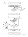
- FIG. 7 is a flow diagram of a process 700 that can be used by a portable media device to communicate with an accessory to control a camera included in the portable media device according to an embodiment of the present invention.
- Process 700 can be performed, e.g., by PMD 202 of FIG. 2 .
- the PMD can identify and authenticate the accessory, e.g., by using the commands in the general lingo. Once authenticated, the accessory can exchange information with the PMD.
- accessory 220 can indicate that PMD 202 should initialize in the camera ON mode, e.g., during identification at block 701 .
- the PMD can receive a request from the accessory to be registered to receive camera notifications, e.g., by using the SetEventNotification command.
- the PMD may send an acknowledgement command to indicate that the request has been successfully received.
- the PMD can also send current camera state information to the accessory, e.g., via the PMDNotification command, as a reply to the SetEventNotification command.
- the PMD can verify whether the camera application is currently active. If it is determined that the camera application is not currently active, process 700 can wait for the camera application to be started at block 710 .
- the PMD can generate a notification indicating that the camera application is currently off.
- a user operating the PMD through its user interface can start the camera application.
- the accessory can remotely start the camera application.
- the PMD can send a camera state notification to the accessory, at block 704 , indicating the change in status of the camera application.
- the PMD may send a notification to the accessory indicating the current camera mode, e.g., still photo or video.
- the camera application controls the mode selection and reports the mode to the PMD's operating system to facilitate notification to the accessory.
- the PMD can check whether it has received any instructions from the accessory to operate the camera. As described above, in some embodiments, the camera can be concurrently controlled by the accessory and the PMD.
- the PMD can check, at block 711 , whether the instructions are to exit the camera application. If the instructions are to exit the camera application, process 700 ends. If the instructions do not correspond to exiting the camera application, the PMD can execute the instructions and operate the camera accordingly at block 708 .
- the instructions can be to change the mode of the camera by toggling between the still photo and video modes.
- the instructions from the accessory can be to capture an image using the current mode of the camera.
- the instructions can include adjustments to camera settings such as zoom, focus, aperture size, or shutter speed.
- the PMD can check whether it has received instructions for operating the camera through the PMD user interface at block 707 . If it is determined that instructions have been received through the PMD user interface, the PMD can operate the camera according to the instructions, at block 708 .
- the instructions can include instructions for capturing an image, instructions for adjusting camera settings, or instructions for disposition of the images previously captured.
- process 700 can check, at block 711 , whether the instructions received from the PMD user interface are to exit the camera application and proceed accordingly if the instructions are to exit the camera application. If the instructions are not to exit the camera application, PMD can operate the camera based on the instructions at block 708 .
- process 700 can wait to receive instructions from the accessory or through the PMD user interface and the process can return to block 706 .
- the PMD can communicate the results of executing the instructions to the accessory and/or the PMD user interface at block 709 .
- the PMD can send any images captured by the camera to the accessory for preview by the accessory, either automatically or in response to requests from the accessory. The accessory may then send instructions regarding disposition of the image to the PMD.
- process 700 described herein is illustrative and that variations and modifications are possible. Acts described as sequential can be executed in parallel, order of acts can be varied, and acts can be modified or combined.
- the PMD may send a camera notification along with the acknowledgement message for the request received at block 702 instead of sending the camera notification as a separate message.
- FIGS. 6 and 7 illustrate one possible sequence of events for controlling the camera by the accessory and the PMD, respectively and include sample camera state transitions that can occur during the respective processes.
- One skilled in the art will realize that other methods for camera control are possible that may include different camera state transitions and/or sequences of transitions than the ones illustrated.
- Embodiments described herein provide for control of a camera included in a PMD.
- the accessory may register with the PMD to receive camera notifications. Once registered, the accessory can automatically receive camera notifications every time there is a change in the camera state, without having to query the PMD for the current state.
- the notifications can include camera status change (e.g., active or inactive), camera mode change (e.g., still photo or video), or camera control information (focus, zoom, aperture size, etc.).
- the accessory can remotely activate the camera by starting a camera application on the PMD that controls the camera, remotely change the camera mode, and remotely provide instructions to operate the camera.
- the accessory and the PMD can concurrently control the camera, i.e., both the PMD and the accessory can send instructions to operate the camera concurrently.
- a user can start video recording by operating the PMD user interface and stop the video recording using the accessory, a user can set the camera mode from the accessory and take a photo/start recording from the PMD user interface.
- the PMD may not allow conflicting commands to be sent to the camera. For example, if the accessory attempts to change the camera mode to still mode while the camera is recording a video, the mode change command can be blocked by the PMD and the accessory notified accordingly.
- the PMD may send the image captured by the camera to the accessory for viewing purposes.
- the accessory may instruct the PMD about disposition of images captured and/or stored on the PMD.
- the camera can be external to the PMD while the camera application can be resident on the PMD. In this instance, the camera can still be controlled using the accessory via the camera application using the above-mentioned methods.
- the external camera can be connected to the accessory I/O interface or a different interface.
- a camera application resident on the PMD can be operated to send control signals to the external camera in order to operate the camera.
- the external camera can be concurrently controlled using the accessory and the PMD.
- the accessory can send instructions to the PMD to instruct the PMD to present a slide-show of the images stored on the PMD.
- the accessory can store images captured by the camera in its cache and these images can be shared with other accessories and/or PMDs.
- the accessory can be programmed to send the CameraButtonStatus command to the PMD periodically, e.g., every 1 sec, for capturing a series of still images over a predetermined period.
- the accessory can send a single instruction to the PMD to capture a series of images at a certain frequency over a given period, e.g., capture an image every 200 seconds over a period of 1 hour.
- the PMD may have an illuminating device, e.g., a light emitting diode (LED) that can be used to provide additional lighting in low light environments to facilitate image capture.
- the illuminating device may work in conjunction with or in lieu of a flash that may be included in the PMD.
- the illuminating device can be controlled by the accessory, e.g., by sending a CameraButtonStatus command with a bitmask bit set to toggle the illuminating device on or off.
- embodiments of the present invention can be realized using any combination of dedicated components and/or programmable processors and/or other programmable devices. While the embodiments described above can make reference to specific hardware and software components, those skilled in the art will appreciate that different combinations of hardware and/or software components can also be used and that particular operations described as being implemented in hardware might also be implemented in software or vice versa.
- Computer programs incorporating various features of the present invention can be encoded on various computer readable media for storage and/or transmission; suitable media include magnetic disk or tape, optical storage media such as compact disk (CD) or DVD (digital versatile disk), flash memory, and the like.
- Computer readable media encoded with the program code can be packaged with a compatible device or provided separately from other devices (e.g., via Internet download).
Abstract
A camera capable of capturing still images and video and included in a portable media device can be controlled remotely using an accessory. The accessory can register with the PMD to automatically receive notifications whenever there is a change in the camera state. The camera states can include mode, operation status, and configuration settings. The accessory can send instructions to a camera application that interfaces with the camera to control the camera. The accessory can remotely activate the camera, change camera mode, and send instructions to operate the camera. The accessory and the PMD can concurrently control the camera. The PMD can send the captured still images and recorded video to the accessory for preview and receive instructions from the accessory on disposition of the still images and the video.
Description
This application is a continuation of U.S. patent application Ser. No. 12/554,228 filed Sep. 4, 2009, the disclosure of which is incorporated herein by reference in its entirety.
The present disclosure relates generally to media players and in particular to controlling a camera in a portable media device.
A portable media device can store a variety of digital information such as audio tracks, video tracks, photos, and other information. Examples of portable media devices are the iPod® and the iPhone™ portable media devices, which are available from Apple Inc. of Cupertino, Calif.
A portable media device can include one or more connectors or ports that can be used to interface with other devices. For example, the connector or port can enable the portable media device to couple to a host computer, be inserted into a docking system, or receive an accessory device. In the case of the iPod®, e.g., a vast array of accessory devices have been developed that can interconnect to the portable media device.
In some instances, a portable media device can have the capability of taking still photos and recording video. For example, a portable media device may include a camera and an associated camera application to control the camera. The camera application can be used to control various aspects of the camera including taking still photographs and recording video.
In addition to taking pictures and recording video with the camera, an accessory can be used to communicate with the portable media device to control the camera remotely to take pictures and record video.
Certain embodiments of the present invention relate to remotely controlling a camera included in a portable media device. A portable media device can have ability to take still photos or record video. In some embodiments, an accessory can control the camera by communicating with the portable media device using a plurality of commands. In an embodiment, the portable media device can have a camera application program resident on the portable media device that can communicate with the camera in order to operate the camera.
In some embodiments, the accessory can register with the portable media device to receive notifications regarding camera state changes. The camera state change notifications can be automatically sent to the accessory upon registration. In an embodiment, the camera state change notifications can be sent asynchronously to the accessory whenever there is a change in the camera state. In some embodiments, the accessory can remotely change the camera mode and remotely operate the camera including activating the camera application. In some embodiments, the camera can be concurrently controlled from the accessory and from the portable media device.
In some embodiments, the portable media device can send the captured still image or the recorded video to the accessory for preview. In some embodiments, the accessory can send instructions to the portable media device about the disposition of the still image or the video. In other embodiments, the accessory can access the still images and videos stored in the portable media device remotely and send instructions to the portable media device for playback of the still images, e.g., slide show, and videos.
The following detailed description, together with the accompanying drawings will provide a better understanding of the nature and advantages of the present invention.
Certain embodiments of the present invention relate to controlling a camera included in a portable media device. A portable media device can have a camera that is capable of capturing still photos and recording video. In an embodiment, the portable media device can have a camera application program resident on the portable media device that can communicate with the camera in order to operate the camera. In some embodiments, an accessory can control the camera using a set of commands exchanged between the portable media device and the accessory. In some embodiments, the accessory can register with the portable media device to receive notifications regarding camera state. Once registered, the accessory can receive notification regarding changes in camera state from the portable media device without having to request an update.
In some embodiments, the accessory can remotely start the camera application if the accessory receives a notification that the camera is inactive. In some embodiments, the accessory can change the camera mode (e.g., between still photo and video modes), instruct the camera to capture a still image, instruct the camera to start video recording, or instruct the camera to stop video recording. An image as described herein can be a still image, e.g., still photo, or a moving image, e.g., a video; hence, “capturing an image” can encompass both still images and video recordings. In some embodiments, the accessory can receive the image captured by the camera for preview and can instruct the portable media device about the disposition of the image, e.g., save or delete. In some embodiments, the accessory can periodically send an image capture command to the portable media device to enable the camera to take a series of still images during a predetermined time. In some embodiments, the accessory can instruct the portable media device to take a series of images over a given time period.
In some embodiments, PMD 100 can communicate with a host computer (not explicitly shown) that executes an image management program. The image management program can allow a user to manage and/or organize the images taken by the camera. The management of the images can include, e.g., storing, deleting, or manipulating an image by subjecting the image to some form of image processing. In some embodiments, PMD 100 can communicate with accessory 150 that is capable of controlling camera 102.
It is to be noted that the PMD and accessory described above are illustrative. PMD 100 can be any device capable of storing and playing media and capturing still images and/or recording video. In some embodiments, PMD 100 can record audio along with the video and can have cellular phone capability. In some embodiments, accessory 150 can have different controls from the ones illustrated in FIG. 1A (e.g., fewer controls or additional controls such as save and delete). In some embodiments, accessory 150 may not have a display.
Accessory I/O interface 214 can allow PMD 202 to communicate with various accessories. For example, accessory I/O interface 214 might support connections to a remote control unit, an external speaker dock, an external video device, or the like. In some embodiments, accessory I/O interface 214 includes a 30-pin connector corresponding to the connector used on iPod® products manufactured and sold by Apple Inc. Alternatively or additionally, accessory I/O interface 214 can include a different connector and/or wireless interface (e.g., Bluetooth or the like).
It will be appreciated that the system configurations and components described herein are illustrative and that variations and modifications are possible. The PMD and/or accessory can have other capabilities not specifically described herein. For example, PMD 202 can play stored media such as songs, audio books, videos, including media obtained from sources other than camera 207. In some embodiments, the accessory can be used to control a camera in the PMD remotely and operate the camera to capture still photos or videos. For example, the accessory can send various commands to the PMD in order to operate the camera and can receive camera related notifications from the PMD. In some embodiments, the camera can be concurrently operated using the accessory and the PMD.
Further, while the PMD and accessory are described herein with reference to particular blocks, it is to be understood that these blocks are defined for convenience of description and are not intended to imply a particular physical arrangement of component parts. Further, the blocks need not correspond to physically distinct components. Blocks can be configured to perform various operations, e.g., by programming a processor or providing appropriate control circuitry, and various blocks might or might not be reconfigurable depending on how the initial configuration is obtained. Embodiments of the present invention can be realized in a variety of devices including electronic devices implemented using any combination of circuitry and software.
Accessory I/O interface 214 of PMD 202 and PMD I/O interface 226 of accessory 220 allow PMD 202 to be connected to accessory 220 and subsequently disconnected from accessory 220. As used herein, PMD 202 and accessory 220 are “connected” whenever a communication channel between accessory I/O interface 214 and PMD I/O interface 226 is open and are “disconnected” whenever the communication channel is closed. Connection can be achieved by physical attachment (e.g., between respective mating connectors of PMD 202 and accessory 220), by an indirect connection such as a cable, or by establishing a wireless communication channel. Similarly, disconnection can be achieved by physical detachment, disconnecting a cable, powering down accessory 220 or PMD 202, or closing the wireless communication channel. Thus, a variety of communication channels can be used, including wired channels such as USB, FireWire, or universal asynchronous receiver/transmitter (“UART”), or wireless channels such as Bluetooth and Wi-Fi. In some embodiments, multiple communication channels between a PMD and an accessory can be open concurrently, or a PMD can be connected to multiple accessories, with each accessory using a different communication channel.
Regardless of the particular communication channel, as long as PMD 202 and accessory 220 are connected to each other, the devices can communicate by exchanging commands and data according to a PMD-specific protocol. The PMD specific protocol can define a format for sending messages between PMD 202 and accessory 220. For instance, the specific protocol can specify that each message be sent in a packet with a header and an optional payload. The header provides basic information (e.g., a start indicator, length of the packet, and a command to be processed by the recipient), while the payload provides any data associated with the command; the amount of associated data can be different for different commands, and some commands can provide for variable-length payloads. In various embodiments, the PMD-specific protocol can define specific commands to indicate an action to be taken by the recipient; to signal completion of a task, change of state, or occurrence of an error; and/or to identify the nature of the associated data. In some embodiments, the commands can be defined such that a particular command is valid in only one direction. The packet can also include error-detection or error-correction codes as known in the art.
The PMD-specific protocol can define a number of “lingoes,” where a “lingo” is a group of related commands that can be supported (or unsupported) by various classes of accessories. In some embodiments, a command can be uniquely identified by a first byte identifying the lingo to which the command belongs and a second byte identifying the particular command within the lingo. Other command structures can also be used. It is not required that all accessories, or all PMDs to which an accessory can be connected, support every lingo defined within the PMD-specific protocol.
In some embodiments, every accessory 220 and every PMD 202 that are designed to be interoperable with each other support at least a “general” lingo that includes commands common to all such devices. The general lingo can include commands enabling the PMD and the accessory to identify themselves to each other and to provide general information about their respective capabilities, including which (if any) other lingoes each supports. The general lingo can also include authentication commands that the PMD can use to verify the purported identity and capabilities of the accessory (or vice versa), and the accessory (or PMD) can be blocked from invoking certain commands or lingoes if the authentication is unsuccessful.
In some embodiments the general lingo can also provide a notification capability. For example, PMD 202 can generate notifications in response to various events that change the status of PMD 202, such as launching or exiting various applications (e.g., camera application 205), changing state within an application (e.g., changing between still-photo and video modes), and so on. Accessory 220, when connected to PMD 202, can “register” to receive all notifications or selected classes of notifications by sending a registration command to PMD 202; an example is described below. Once accessory 220 has registered for a particular class (or classes) of notifications, PMD 202 automatically begins to send notifications to accessory 220 whenever any event within the registered class(es) occurs. Notification conveniently allows accessory 220 to maintain current information about the status of PMD 202 without having to send requests for status information. In some embodiments, the notifications about the changes in camera state can be communicated to the accessory asynchronously. Camera 207 can change states independent of accessory 220 and accessory can get notified of the change in state asynchronously.
A PMD-specific protocol can also include various other lingoes, such as a simple remote lingo that allows accessory 220 to send a command indicating a function of PMD 202 to be invoked, a remote user interface lingo that can be used to communicate commands and data related to replicating all or part of a user interface of PMD 202 on accessory 220 (thereby supporting a more advanced remote control), a camera lingo that allows accessory 220 to control various settings of camera 207, a storage lingo that allows accessory 220 to store data on PMD 202, and so on. Any lingo or combination of lingoes or other commands or groups of commands can be used in connection with a PMD-specific protocol.
PMD State Diagram
In Photo Preview state 302, PMD 202 can receive input for operating the camera to take a still image, change the camera settings, e.g., focus, zoom, etc., review previously captured images, change camera mode, and the like. In some embodiments, PMD 202 can remain in the Photo Preview state 302 until the camera application quits, e.g., “CameraOFF” event, or PMD 202 receives a command to change camera mode. In the event that PMD 202 receives a command to capture a still image, e.g., “CameraAction” event, PMD 202 transitions to Photo Taken state 303 to capture the current image from the camera sensor into memory or other storage medium. In some embodiments, upon capturing the still image, PMD 202 returns to Photo Preview state 302.
In some embodiments, when PMD 202 is in Photo Preview state 304, it can receive a command to change the camera mode, resulting in a “ToggleMode” event. The ToggleMode event can occur in response to a command received from accessory 220 or via the user interface of PMD 202 to change the camera mode. Upon occurrence of the ToggleMode event, PMD 202 transitions to Video Preview state 304. Similarly, if PMD 202 is in Video Preview state 304 and the ToggleMode event occurs, PMD 202 transitions to Photo Preview state 302.
In Video Preview state 304, PMD 202 can receive input for operating the camera to capture video, changing camera settings, changing camera mode, or turning the camera off. If PMD 202 receives a command to capture video, e.g., CameraAction event, PMD 202 transitions to Video Recording state 305. PMD 202 can stay in Video Recording state 305 until it receives a command to stop recording the video, e.g., CameraAction event, or camera application 205 is turned off, e.g., CameraOFF event.
It will be appreciated that the various states described in reference to FIG. 3 are for illustrative purposes only. Once skilled in the art will realize that various other states are possible depending on the PMD capabilities.
Accessory State Diagram
If, while accessory 220 is in Photo with Indicator OFF state 401, it receives notification that camera 207 has changed its state to Video Preview, accessory 220 can transition to Video with Indicator OFF state 402. As described above, camera 207 may change its state based on instructions received from accessory 220 or PMD 202. In the Video with Indicator OFF state 402, accessory 220 can receive a notification from PMD 202 that may cause accessory 220 to change to Photo with Indicator OFF state 401, e.g., camera mode change or camera off notification. In addition, while in Video with Indicator OFF state 402, if accessory 220 receives notification that camera 207 has begun to capture a video, e.g., video recording notification, accessory 220 can transition to Video with Indicator ON state 405. In some embodiments, accessory 220 can transition directly to Video with Indicator ON state 405 from Photo with Indicator OFF state 401 upon receiving an appropriate notification from PMD 202.
It will be appreciated that the various states described in reference to FIGS. 3 and 4 are for illustrative purposes only. One skilled in the art will realize that various other states are possible depending on the accessory capabilities.
In some embodiments, accessory 220 can be stateless in that the accessory may not have states that correspond to the states of the camera. For example, the camera may change states as illustrated in FIG. 3 , but there may not be any corresponding state changes for the accessory. The commands sent by the accessory will operate the camera based on the state of the camera without the accessory providing specific commands. For example, if the camera is in a photo preview state, pressing the action button on accessory 150 of FIG. 1B can result in the camera capturing an image without the accessory specifically instructing the camera to capture an image. The accessory can operate independent of the camera state. If the camera is in photo preview state and the mode button on the accessory is selected, the accessory can send a command to the camera to change modes without knowing the current camera mode or specifying a particular new mode for the camera. In some embodiments, the camera can change states without any instructions from the accessory, e.g., by receiving instructions from the PMD user interface.
The SetEventNotification command can be sent by accessory 220 to PMD 202 to register for notifications of various changes to the PMD's state. In one embodiment, the payload of the SetEventNotification command includes a bitmask in which each bit is associated with a different class of notifications. For example, if PMD 202 has multiple functions, the notifications can be grouped into classes according to function (e.g., camera, stored media playback, telephony, data network access, navigation, etc.), and accessory 220 can register for classes that will affect its operation. Thus, for example, an accessory that can control camera functionality can register for camera notifications without receiving, e.g., telephony or navigation notifications. In some embodiments, PMD 202 can return an acknowledgement (not explicitly shown in FIG. 3 ) to confirm receipt of the SetEventNotification command.
The PMDNotification command can be sent by PMD 202 to accessory 220 to notify accessory 220 of a state transition or other event that may affect operation of the accessory. The payload can include a notification message indicating the type of event (e.g., using a byte code) and optionally other information that depends on the type of event. In some embodiments, PMD 202 sends notifications only for events in a class for which the accessory has registered using the SetEventNotification command. For example, in one embodiment, there can be defined a “camera” class of notifications. The camera class can include notifications corresponding to, e.g., the CameraON and CameraOFF events of FIG. 3 , as well as notifications related to operation of camera such as capturing a still image or starting and stopping a video recording. In particular, in some embodiments, notifications can be sent for each CameraAction event shown in FIG. 3 .
The CameraButtonStatus command can be sent from the accessory to the PMD to provide an instruction for operating the camera. The payload of this command can include a bit mask in which different bits map to different camera operations. For example, one bit may map to a camera mode toggle between video and still photo modes and another bit may map to a Camera Action operation. The command can be used to send the desired instruction by setting the corresponding bit(s) in the bitmask. For instance, the CameraButtonStatus command can be used to toggle the camera mode between Photo Preview and Video Preview by setting the appropriate bit in the bit mask. In some embodiments, this command can be used to instruct the camera to capture a still photo or record a video depending on the mode of the camera. For instance, if a user of the accessory desires to capture a still photo but the PMDNotification command indicates that the camera is in a Video Preview mode, the user can instruct the accessory to send the CameraButtonStatus command with the appropriate bit set to toggle the camera mode to Photo Preview mode. Once the PMD confirms the change in mode via the PMDNotification command, the accessory can send the CameraButtonStatus command with the bit corresponding to Camera Action being set. The camera can then capture a still image. A single Camera Action bit of the CameraButtonStatus command can be associated with multiple camera operations such as taking still photo if the camera is in Photo Preview mode, starting video recording if the camera is in Video Preview mode, and stopping video recording if the camera is in Video Recording mode.
It will be appreciated that the commands described herein are illustrative and that variations and modifications are possible. For instance, additional commands can be used to facilitate communication of camera state information and operation instructions between the PMD and the accessory. For example, the accessory can send a GetEventNotification command to the PMD to confirm the event classes for which the accessory is currently registered to receive notifications. The PMD can respond with a RetEventNotification command informing the accessory about the event classes that the accessory is currently registered for and if the currently registered event classes are not the ones the accessory wishes to remain registered for, the subscription of the event classes can be changed, e.g., using the SetEventNotification command. In some embodiments, the accessory may query the PMD about all the event classes that the PMD supports for providing notifications, e.g., using a GetSupportedEventNotification command. The PMD may respond with a RetSupportedEventNotification command. The payload of the RetSupportedEventNotification command can include a bitmask indicating all possible event classes for which the PMD can generate notifications. In some embodiments, each bit of the bitmask can correspond to an event or an event class. Further, not all of the commands described herein need be supported, and other protocols can be used.
In some embodiments, PMD 202 can generate camera state notifications and communicate the notifications to the accessory. In some embodiments, these notifications are provided to the accessory asynchronously, i.e., without the accessory requesting the notification. In some embodiments, before PMD 202 can send the camera state notifications, the accessory may have to register with PMD 202, e.g., using the SetEventNotification command, to receive the notifications. Once the accessory registers with PMD 202, it can automatically receive notifications about changes in the state of the camera. Camera state notifications can include information about, camera mode (photo or video), camera operation (video recording in progress, photo taken, etc.), camera status (active (on) or inactive (off)), whether the camera application is currently running or not, etc. Every time there is change in the state of the camera, PMD 202 can send a notification to the accessory. In some embodiments, a notification regarding camera state may be sent to the accessory even if a command to change the camera state does not result in an actual change of state of the camera. In addition, in some embodiments additional commands can be provided to allow accessory 220 to direct camera application 205 to control various settings of the camera including, zoom, shutter speed, aperture size, flash, focus, and the like.
At block 602, the accessory can register with the PMD for receiving camera state notifications e.g., by sending the SetEventNotification command with appropriate parameters. At block 603, the accessory can receive a camera state change notification from the PMD indicating the current state of the camera e.g., via the PMDNotification command. At block 604, the accessory can analyze the received notification to check whether the camera application is currently active. If it is determined that the camera application is not currently active, the accessory can wait at block 611 until another notification is received and process 600 returns to block 603. In an alternative embodiment, if at block 604, it is determined that the camera application is not active, the accessory can send a command to the PMD to activate the camera application, e.g., by using the CameraButtonStatus command. In some embodiments, this command can be sent automatically by the accessory or in response to user input requiring camera activation. Once it is determined, at block 604, that the camera application is active, the accessory can receive current camera mode information at block 605 e.g., via the PMDNotification command.
Once the current camera mode is received by the accessory, the accessory can present the current mode information at block 606, e.g., on its display, and wait for further input. At block 607, the accessory can receive input, e.g., from a user operating the accessory. Once the accessory receives an input, the accessory can check, at block 608, to determine if the input corresponds to a request to change the camera mode. If it is determined that the input is not to change the camera mode, processing can proceed to block 609. If it is determined that the input is a request to change camera mode, the accessory can send instructions to the PMD to change the camera mode at block 612, e.g., using the CameraButtonStatus command. In some embodiments, block 612 can include receiving notification of the new camera mode. Once the accessory sends the instruction to change camera mode at block 612, process 600 can return to block 605 where the PMD can receive notification of the camera mode change and then await further inputs at block 607.
At block 609, the accessory can check whether the received input corresponds to an instruction for operating the camera. If it is determined that the received input corresponds to an instruction for operating the camera, the accessory can send instructions to the PMD to operate the camera at block 610, e.g., using the CameraButtonStatus command. For example, the instructions to operate the camera can include instructions to change camera settings or instructions to capture an image. After sending the instructions to the PMD and receiving response from the PMD, process 600 can return to block 607 to await further input. If at block 609, it is determined that the received input is not to operate the camera, process 600 can return to block 607 and the accessory can check whether it has received any new input. Process 600 can continue until the accessory is disconnected from the PMD. In some embodiments, at block 607, instead of a user input, the input received can be a notification regarding change in the camera state. For example, if a user instructs the camera to capture an image by operating the user interface of the PMD after the accessory has received the camera mode information, e.g., Photo Preview, at block 605, the input received at block 607 can be the new camera state e.g., Photo Taken.
It will be appreciated that process 600 described herein is illustrative and that variations and modifications are possible. Acts described as sequential can be executed in parallel, order of acts can be varied, and acts can be modified or combined. For instance, the accessory may send the command to change the camera mode to a desired mode before the PMD sends a notification about the current camera mode. In some embodiments, the accessory may not wait for the PMD to confirm a mode change before sending the instructions to operate the camera. In some embodiments, after the camera captures an image, the PMD may send the picture to the accessory for display on the accessory either automatically or in response to an image request command sent by the accessory. In some embodiments, the accessory may provide disposition instructions for the image to the PMD once it is previewed, e.g., store the image, delete the image, etc.
At block 702, the PMD can receive a request from the accessory to be registered to receive camera notifications, e.g., by using the SetEventNotification command. In some embodiments, the PMD may send an acknowledgement command to indicate that the request has been successfully received. In some embodiments, the PMD can also send current camera state information to the accessory, e.g., via the PMDNotification command, as a reply to the SetEventNotification command. At block 703, the PMD can verify whether the camera application is currently active. If it is determined that the camera application is not currently active, process 700 can wait for the camera application to be started at block 710. In some embodiments, the PMD can generate a notification indicating that the camera application is currently off. In some embodiments, a user operating the PMD through its user interface can start the camera application. In an alternative embodiment, the accessory can remotely start the camera application.
If it is determined at block 703 that the camera application is currently active, or upon activation of the camera application, the PMD can send a camera state notification to the accessory, at block 704, indicating the change in status of the camera application. At block 705, the PMD may send a notification to the accessory indicating the current camera mode, e.g., still photo or video. In some embodiments, the camera application controls the mode selection and reports the mode to the PMD's operating system to facilitate notification to the accessory. At block 706, the PMD can check whether it has received any instructions from the accessory to operate the camera. As described above, in some embodiments, the camera can be concurrently controlled by the accessory and the PMD. If it is determined at block 706 that PMD has received instructions from the accessory, the PMD can check, at block 711, whether the instructions are to exit the camera application. If the instructions are to exit the camera application, process 700 ends. If the instructions do not correspond to exiting the camera application, the PMD can execute the instructions and operate the camera accordingly at block 708. In some embodiments, the instructions can be to change the mode of the camera by toggling between the still photo and video modes. In some embodiments, the instructions from the accessory can be to capture an image using the current mode of the camera. In yet other embodiments, the instructions can include adjustments to camera settings such as zoom, focus, aperture size, or shutter speed.
If it is determined at block 706 that no instructions have been received from the accessory, the PMD can check whether it has received instructions for operating the camera through the PMD user interface at block 707. If it is determined that instructions have been received through the PMD user interface, the PMD can operate the camera according to the instructions, at block 708. As described above, the instructions can include instructions for capturing an image, instructions for adjusting camera settings, or instructions for disposition of the images previously captured. In some embodiments, process 700 can check, at block 711, whether the instructions received from the PMD user interface are to exit the camera application and proceed accordingly if the instructions are to exit the camera application. If the instructions are not to exit the camera application, PMD can operate the camera based on the instructions at block 708. If it is determined, that no instructions are received at block 707, process 700 can wait to receive instructions from the accessory or through the PMD user interface and the process can return to block 706. Upon executing the instructions received from either the accessory or the PMD user interface, the PMD can communicate the results of executing the instructions to the accessory and/or the PMD user interface at block 709. In some embodiments, the PMD can send any images captured by the camera to the accessory for preview by the accessory, either automatically or in response to requests from the accessory. The accessory may then send instructions regarding disposition of the image to the PMD.
It will be appreciated that process 700 described herein is illustrative and that variations and modifications are possible. Acts described as sequential can be executed in parallel, order of acts can be varied, and acts can be modified or combined. For instance, the PMD may send a camera notification along with the acknowledgement message for the request received at block 702 instead of sending the camera notification as a separate message.
It is to be noted that FIGS. 6 and 7 illustrate one possible sequence of events for controlling the camera by the accessory and the PMD, respectively and include sample camera state transitions that can occur during the respective processes. One skilled in the art will realize that other methods for camera control are possible that may include different camera state transitions and/or sequences of transitions than the ones illustrated.
Embodiments described herein provide for control of a camera included in a PMD. In some embodiments, the accessory may register with the PMD to receive camera notifications. Once registered, the accessory can automatically receive camera notifications every time there is a change in the camera state, without having to query the PMD for the current state. In some embodiments, the notifications can include camera status change (e.g., active or inactive), camera mode change (e.g., still photo or video), or camera control information (focus, zoom, aperture size, etc.). In some embodiments, the accessory can remotely activate the camera by starting a camera application on the PMD that controls the camera, remotely change the camera mode, and remotely provide instructions to operate the camera. In some embodiments, the accessory and the PMD can concurrently control the camera, i.e., both the PMD and the accessory can send instructions to operate the camera concurrently. For example, a user can start video recording by operating the PMD user interface and stop the video recording using the accessory, a user can set the camera mode from the accessory and take a photo/start recording from the PMD user interface. In some embodiments, the PMD may not allow conflicting commands to be sent to the camera. For example, if the accessory attempts to change the camera mode to still mode while the camera is recording a video, the mode change command can be blocked by the PMD and the accessory notified accordingly. In some embodiments, the PMD may send the image captured by the camera to the accessory for viewing purposes. In some embodiments, the accessory may instruct the PMD about disposition of images captured and/or stored on the PMD.
In some embodiments, the camera can be external to the PMD while the camera application can be resident on the PMD. In this instance, the camera can still be controlled using the accessory via the camera application using the above-mentioned methods. In some embodiments, the external camera can be connected to the accessory I/O interface or a different interface. A camera application resident on the PMD can be operated to send control signals to the external camera in order to operate the camera. In some embodiments, the external camera can be concurrently controlled using the accessory and the PMD.
While the invention has been described with respect to specific embodiments, those skilled in the art will recognize that numerous modifications are possible. For instance, the accessory can send instructions to the PMD to instruct the PMD to present a slide-show of the images stored on the PMD. In some embodiments, the accessory can store images captured by the camera in its cache and these images can be shared with other accessories and/or PMDs. In some embodiments, the accessory can be programmed to send the CameraButtonStatus command to the PMD periodically, e.g., every 1 sec, for capturing a series of still images over a predetermined period. In some embodiments, the accessory can send a single instruction to the PMD to capture a series of images at a certain frequency over a given period, e.g., capture an image every 200 seconds over a period of 1 hour. In some embodiments, the PMD may have an illuminating device, e.g., a light emitting diode (LED) that can be used to provide additional lighting in low light environments to facilitate image capture. The illuminating device may work in conjunction with or in lieu of a flash that may be included in the PMD. In some embodiments, the illuminating device can be controlled by the accessory, e.g., by sending a CameraButtonStatus command with a bitmask bit set to toggle the illuminating device on or off.
In addition, embodiments of the present invention can be realized using any combination of dedicated components and/or programmable processors and/or other programmable devices. While the embodiments described above can make reference to specific hardware and software components, those skilled in the art will appreciate that different combinations of hardware and/or software components can also be used and that particular operations described as being implemented in hardware might also be implemented in software or vice versa.
Computer programs incorporating various features of the present invention can be encoded on various computer readable media for storage and/or transmission; suitable media include magnetic disk or tape, optical storage media such as compact disk (CD) or DVD (digital versatile disk), flash memory, and the like. Computer readable media encoded with the program code can be packaged with a compatible device or provided separately from other devices (e.g., via Internet download).
Thus, although the invention has been described with respect to specific embodiments, it will be appreciated that the invention is intended to cover all modifications and equivalents within the scope of the following claims.
Claims (23)
1. A method comprising:
sending, by an accessory to a portable device having a camera that is concurrently operable in response to commands from the accessory and signals from a user interface of the portable device, a request to register for camera status notifications to be sent by the portable device in response to processing the commands from the accessory and the signals from the user interface for the portable device;
receiving, by the accessory from the portable device, a first camera status notification identifying a current camera mode from a plurality of camera modes, the plurality of camera modes including a still-image mode in which the camera of the portable device is ready to capture a still image and a video mode in which the camera of the portable device is ready to record a video;
receiving, by the accessory, a first user input indicating that the current camera mode should be changed;
in response to the first user input, sending, by the accessory, a mode change command to the portable device;
receiving, by the accessory from the portable device, a second camera status notification identifying an updated camera mode;
receiving, by the accessory, a second user input indicating that an image capture operation should be performed;
in response to the second user input, sending, by the accessory, an image capture command to the portable device; and
receiving, by the accessory, a third camera status notification indicating that an image capture operation has been performed, wherein the third camera status notification includes either an indication that a still image has been captured or an indication that recording of a video has been started.
2. The method of claim 1 further comprising:
in response to receiving the third camera status notification, presenting an output to the user indicating that the image capture operation has been performed.
3. The method of claim 2 wherein presenting the output to the user includes illuminating a visual indicator.
4. The method of claim 3 wherein, in the event that the third camera status notification includes the indication that recording of a video has been started, the visual indicator remains illuminated until a fourth camera status notification is received, the fourth camera status notification including an indication that recording of the video has been stopped.
5. The method of claim 1 wherein, in the event that the second user input is received before the second camera status notification is received, the accessory waits to send the image capture command until the second camera status notification is received.
6. The method of claim 1 further comprising:
in response to receiving the second camera status notification, presenting an output to the user indicating the updated camera mode.
7. An accessory comprising:
a user interface including a first input control operable as a camera mode button and a second input control operable as a camera action button;
a device interface to communicate with a portable device having a camera that is concurrently operable in response to commands from the accessory and signals from a user interface of the portable device; and
a processor coupled to the user interface and the device interface, wherein the processor is configured to communicate with the portable device via the device interface using a plurality of commands, the plurality of commands including:
a first command sendable by the accessory, the first command requesting registration for camera status notifications;
a second command receivable by the accessory, the second command including a camera status notification, wherein the camera status notification includes information indicative of a current operational state of the camera of the portable device and wherein receipt of the second command informs the processor that the operational state of the camera has changed; and
a third command sendable by the accessory responsive to user operation of the first or second input control, the third command including either an indication that the user has operated the camera mode button or an indication that the user has operated the camera action button,
wherein the second command is receivable asynchronously with respect to sending of the third command.
8. The accessory of claim 7 wherein the information indicative of the current operational state of the camera includes a current camera mode identifier selected from a plurality of camera modes identifiers, the plurality of camera mode identifiers including a still-mode identifier indicating that the camera is ready to capture a still image and a video-mode identifier indicating that the camera is ready to record a video.
9. The accessory of claim 7 wherein the user interface further includes a visual indicator and wherein the processor is further configured to illuminate or de-illuminate the visual indicator in response to receiving the second command.
10. The accessory of claim 7 wherein the information indicative of the current operational state of the camera includes information indicating whether the camera is active or inactive.
11. The accessory of claim 10 wherein the plurality of commands further includes:
a fourth command sendable by the accessory to instruct the portable device to activate the camera.
12. A method comprising:
receiving, by a portable device having a camera and a user interface, a request from an accessory to register for camera status notifications;
determining, by the portable device, a current camera mode of the camera, the current camera mode selected from a plurality of camera modes including a still-image mode in which the camera is ready to capture a still image and a video mode in which the camera is ready to record a video;
sending, by the portable device to the accessory, a first camera status notification identifying the current camera mode;
receiving, by the portable device, a mode change command from the accessory;
in response to the mode change command, changing the current camera mode to a next one of the plurality of camera modes, and sending to the accessory a second camera status notification indicating the changed current camera mode;
receiving, by the portable device, a first instruction to capture an image, wherein the first instruction to capture an image is received as either an image capture command from the accessory or an image capture signal from the user interface of the portable device; and
in response to the first instruction to capture an image:
capturing a first still image in the event that the first image capture command is received while the current camera mode is the still-image mode;
beginning to record a video in the event that the first image capture command is received while the current camera mode is the video mode; and
sending, to the accessory, a third camera status notification indicating that a first image capture operation has been performed.
13. The method of claim 12 wherein the third camera status notification further indicates whether a still image was captured or video recording was begun.
14. The method of claim 12 further comprising, after sending the third camera status notification:
receiving, by the portable device, a second instruction to capture an image, wherein the second instruction to capture an image is received as either an image capture command from the accessory or an image capture signal from the user interface of the portable device; and
in response to the second instruction to capture an image:
capturing a second still image in the event that the second image capture command is received while the current camera mode is the still-image mode;
ending recording of the video image in the event that the second image capture command is received while the current camera mode is the video mode; and
sending, to the accessory, a fourth camera status notification indicating that a second image capture operation has been performed.
15. The method of claim 14 wherein one of the first instruction to capture an image or the second instruction to capture an image is received as an image capture command from the accessory and the other of the first instruction to capture an image or the second instruction to capture an image is received as an image capture signal from the user interface of the portable device.
16. The method of claim 12 wherein the first instruction to capture an image is received as an image capture command from the accessory.
17. The method of claim 12 wherein the first instruction to capture an image is received an image capture signal from the user interface of the portable device.
18. The method of claim 12 further comprising:
in the event that the camera is inactive, sending, by the portable device, a fourth camera status notification indicating that the camera is inactive.
19. The method of claim 18 further comprising:
receiving, by the portable device, an instruction from the accessory to activate the camera.
20. A portable device comprising:
a user interface;
a camera operable in a plurality of camera modes including a still mode to capture still images and a video mode to record video;
an accessory interface to communicate with an accessory; and
a processor coupled to the user interface, the camera, and the accessory interface, wherein the processor is configured to communicate with the accessory via the accessory interface using a plurality of commands, the plurality of commands including:
a first command receivable by the portable device, the first command requesting registration for camera status notifications;
a second command sendable by the portable device, the second command including a camera status notification, wherein the camera status notification includes information indicative of an operational state of the camera and wherein the processor is configured to send the second command in response to a change in the operational state of the camera; and
a third command receivable by the portable device, the third command including either an indication that the user has operated a mode button of the accessory or an indication that the user has operated an action button of the accessory,
wherein the second command is sendable asynchronously with respect to receiving of the third command; and
wherein the processor is further configured to:
change a current camera mode of the camera to a next one of the plurality of camera modes in response to receiving the third command, in the event that that the third command includes the indication that the user has operated the mode button;
operate the camera to capture a still image in response to receiving the third command, in the event that the third command includes the indication that the user has operated the action button and the current camera mode is the still mode; and
operate the camera to start or stop video recording in response to receiving the third command, in the event that the third command includes the indication that the user has operated the camera action button and the current camera mode is the video mode;
receive user input signals from the user interface; and
operate the camera in response to the user input signals,
wherein the processor is configured such that the camera is concurrently operable using the user input signals from the user interface and the commands from the accessory.
21. The portable device of claim 20 wherein the processor is further configured to:
send a first instance of the second command to the accessory in response to changing the current camera mode, the first instance of the second command including an indication of the camera mode to which the current camera mode was changed;
send a second instance of the second command to the accessory in response to capturing a still image, the second instance of the second command indicating that a still image has been captured;
send a third instance of the second command to the accessory in response to starting or stopping video recording, the third instance of the second command indicating whether video recording is started or stopped.
22. The portable device of claim 20 wherein the plurality of commands further includes:
a fourth command receivable by the portable device, the fourth command instructing the portable device to activate the camera.
23. The portable device of claim 20 wherein the processor is further configured to send a representation of a captured still image or video recording to the accessory.
Priority Applications (1)
| Application Number | Priority Date | Filing Date | Title |
|---|---|---|---|
| US14/163,119 US9325892B2 (en) | 2009-09-04 | 2014-01-24 | Systems and methods for remote camera control |
Applications Claiming Priority (2)
| Application Number | Priority Date | Filing Date | Title |
|---|---|---|---|
| US12/554,228 US8675084B2 (en) | 2009-09-04 | 2009-09-04 | Systems and methods for remote camera control |
| US14/163,119 US9325892B2 (en) | 2009-09-04 | 2014-01-24 | Systems and methods for remote camera control |
Related Parent Applications (1)
| Application Number | Title | Priority Date | Filing Date |
|---|---|---|---|
| US12/554,228 Continuation US8675084B2 (en) | 2009-09-04 | 2009-09-04 | Systems and methods for remote camera control |
Publications (2)
| Publication Number | Publication Date |
|---|---|
| US20140354838A1 US20140354838A1 (en) | 2014-12-04 |
| US9325892B2 true US9325892B2 (en) | 2016-04-26 |
Family
ID=43647460
Family Applications (2)
| Application Number | Title | Priority Date | Filing Date |
|---|---|---|---|
| US12/554,228 Active 2032-11-14 US8675084B2 (en) | 2009-09-04 | 2009-09-04 | Systems and methods for remote camera control |
| US14/163,119 Active US9325892B2 (en) | 2009-09-04 | 2014-01-24 | Systems and methods for remote camera control |
Family Applications Before (1)
| Application Number | Title | Priority Date | Filing Date |
|---|---|---|---|
| US12/554,228 Active 2032-11-14 US8675084B2 (en) | 2009-09-04 | 2009-09-04 | Systems and methods for remote camera control |
Country Status (1)
| Country | Link |
|---|---|
| US (2) | US8675084B2 (en) |
Families Citing this family (260)
| Publication number | Priority date | Publication date | Assignee | Title |
|---|---|---|---|---|
| US8645137B2 (en) | 2000-03-16 | 2014-02-04 | Apple Inc. | Fast, language-independent method for user authentication by voice |
| US8677377B2 (en) | 2005-09-08 | 2014-03-18 | Apple Inc. | Method and apparatus for building an intelligent automated assistant |
| US9318108B2 (en) | 2010-01-18 | 2016-04-19 | Apple Inc. | Intelligent automated assistant |
| US8977255B2 (en) | 2007-04-03 | 2015-03-10 | Apple Inc. | Method and system for operating a multi-function portable electronic device using voice-activation |
| US10002189B2 (en) | 2007-12-20 | 2018-06-19 | Apple Inc. | Method and apparatus for searching using an active ontology |
| US9330720B2 (en) | 2008-01-03 | 2016-05-03 | Apple Inc. | Methods and apparatus for altering audio output signals |
| US8996376B2 (en) | 2008-04-05 | 2015-03-31 | Apple Inc. | Intelligent text-to-speech conversion |
| US10831093B1 (en) | 2008-05-19 | 2020-11-10 | Spatial Cam Llc | Focus control for a plurality of cameras in a smartphone |
| US20110098083A1 (en) | 2008-05-19 | 2011-04-28 | Peter Lablans | Large, Ultra-Thin And Ultra-Light Connectable Display For A Computing Device |
| US20100030549A1 (en) | 2008-07-31 | 2010-02-04 | Lee Michael M | Mobile device having human language translation capability with positional feedback |
| US8676904B2 (en) | 2008-10-02 | 2014-03-18 | Apple Inc. | Electronic devices with voice command and contextual data processing capabilities |
| AU2009319665B2 (en) | 2008-11-26 | 2015-08-20 | Calgary Scientific Inc. | Method and system for providing remote access to a state of an application program |
| US8788655B2 (en) | 2008-12-19 | 2014-07-22 | Openpeak Inc. | Systems for accepting and approving applications and methods of operation of same |
| US8612582B2 (en) | 2008-12-19 | 2013-12-17 | Openpeak Inc. | Managed services portals and method of operation of same |
| US8856322B2 (en) | 2008-12-19 | 2014-10-07 | Openpeak Inc. | Supervisory portal systems and methods of operation of same |
| US8745213B2 (en) | 2008-12-19 | 2014-06-03 | Openpeak Inc. | Managed services platform and method of operation of same |
| US9753746B2 (en) | 2008-12-19 | 2017-09-05 | Paul Krzyzanowski | Application store and intelligence system for networked telephony and digital media services devices |
| US8650290B2 (en) | 2008-12-19 | 2014-02-11 | Openpeak Inc. | Portable computing device and method of operation of same |
| US8713173B2 (en) | 2008-12-19 | 2014-04-29 | Openpeak Inc. | System and method for ensuring compliance with organizational policies |
| US8615581B2 (en) | 2008-12-19 | 2013-12-24 | Openpeak Inc. | System for managing devices and method of operation of same |
| US20120311585A1 (en) | 2011-06-03 | 2012-12-06 | Apple Inc. | Organizing task items that represent tasks to perform |
| US10241752B2 (en) | 2011-09-30 | 2019-03-26 | Apple Inc. | Interface for a virtual digital assistant |
| US10241644B2 (en) | 2011-06-03 | 2019-03-26 | Apple Inc. | Actionable reminder entries |
| US9431006B2 (en) | 2009-07-02 | 2016-08-30 | Apple Inc. | Methods and apparatuses for automatic speech recognition |
| US8675084B2 (en) * | 2009-09-04 | 2014-03-18 | Apple Inc. | Systems and methods for remote camera control |
| US10276170B2 (en) | 2010-01-18 | 2019-04-30 | Apple Inc. | Intelligent automated assistant |
| US8682667B2 (en) | 2010-02-25 | 2014-03-25 | Apple Inc. | User profiling for selecting user specific voice input processing information |
| EP2393000B1 (en) * | 2010-06-04 | 2019-08-07 | Lg Electronics Inc. | Mobile terminal capable of providing multiplayer game and method of controlling operation of the mobile terminal |
| LT2617186T (en) | 2010-09-13 | 2022-02-25 | Contour Ip Holding, Llc | Portable digital video camera configured for remote image acquisition control and viewing |
| US8650658B2 (en) | 2010-10-25 | 2014-02-11 | Openpeak Inc. | Creating distinct user spaces through user identifiers |
| JP2012124653A (en) * | 2010-12-07 | 2012-06-28 | Canon Inc | Encoder, encoding method, and program |
| US9124436B2 (en) | 2010-12-16 | 2015-09-01 | Cellco Partnership | Intelligent automated data usage upgrade recommendation |
| US9741084B2 (en) | 2011-01-04 | 2017-08-22 | Calgary Scientific Inc. | Method and system for providing remote access to data for display on a mobile device |
| EP2661654A4 (en) * | 2011-01-04 | 2014-07-09 | Calgary Scient Inc | A method and system of controlling a remote controlled device in a remote controlled surgical procedure |
| US10082892B2 (en) | 2011-01-10 | 2018-09-25 | Apple Inc. | Button functionality |
| JP2012174042A (en) * | 2011-02-22 | 2012-09-10 | Canon Inc | Document management device, method for control of document management device, and program |
| US9262612B2 (en) | 2011-03-21 | 2016-02-16 | Apple Inc. | Device access using voice authentication |
| US9043455B1 (en) | 2011-04-06 | 2015-05-26 | Cellco Partnership | Universal data remote |
| US9723092B1 (en) * | 2011-04-07 | 2017-08-01 | Cellco Partnership | Universal data remote application framework |
| US9117483B2 (en) | 2011-06-03 | 2015-08-25 | Michael Edward Zaletel | Method and apparatus for dynamically recording, editing and combining multiple live video clips and still photographs into a finished composition |
| US10057736B2 (en) | 2011-06-03 | 2018-08-21 | Apple Inc. | Active transport based notifications |
| JP5868038B2 (en) * | 2011-06-28 | 2016-02-24 | キヤノン株式会社 | Imaging apparatus, control method therefor, program, and storage medium |
| US9729780B2 (en) | 2011-07-08 | 2017-08-08 | Visual Retailing Holding B.V. | Imaging apparatus and controller for photographing products |
| CA2844871C (en) | 2011-08-15 | 2021-02-02 | Calgary Scientific Inc. | Non-invasive remote access to an application program |
| US8994660B2 (en) | 2011-08-29 | 2015-03-31 | Apple Inc. | Text correction processing |
| JP5874279B2 (en) | 2011-09-30 | 2016-03-02 | ブラザー工業株式会社 | Image processing apparatus and portable terminal |
| WO2013046015A1 (en) | 2011-09-30 | 2013-04-04 | Calgary Scientific Inc. | Uncoupled application extensions including interactive digital surface layer for collaborative remote application sharing and annotating |
| JP5834726B2 (en) * | 2011-09-30 | 2015-12-24 | ブラザー工業株式会社 | Mobile device |
| US8695060B2 (en) | 2011-10-10 | 2014-04-08 | Openpeak Inc. | System and method for creating secure applications |
| US9294572B2 (en) | 2011-11-11 | 2016-03-22 | Calgary Scientific Inc. | Session transfer and suspension in a remote access application framework |
| CN104040946B (en) | 2011-11-23 | 2017-07-14 | 卡尔加里科学公司 | For shared and meeting the method and system of the remote application that cooperates |
| US8996729B2 (en) | 2012-04-12 | 2015-03-31 | Nokia Corporation | Method and apparatus for synchronizing tasks performed by multiple devices |
| CN104137048B (en) | 2011-12-28 | 2019-10-25 | 诺基亚技术有限公司 | The opening example of application is provided |
| US10134385B2 (en) | 2012-03-02 | 2018-11-20 | Apple Inc. | Systems and methods for name pronunciation |
| EP2823411A4 (en) * | 2012-03-10 | 2015-12-09 | Evado Holdings Pty Ltd | A method and system of application development for multiple device client platforms |
| US8934045B2 (en) | 2012-03-12 | 2015-01-13 | Apple Inc. | Digital camera system having remote control |
| US20130235234A1 (en) | 2012-03-12 | 2013-09-12 | Megan Lyn Cucci | Digital camera having multiple image capture systems |
| US10235014B2 (en) | 2012-05-09 | 2019-03-19 | Apple Inc. | Music user interface |
| US10097496B2 (en) | 2012-05-09 | 2018-10-09 | Apple Inc. | Electronic mail user interface |
| US10417037B2 (en) | 2012-05-15 | 2019-09-17 | Apple Inc. | Systems and methods for integrating third party services with a digital assistant |
| US20140210989A1 (en) * | 2012-06-01 | 2014-07-31 | Mark S. Olsson | Systems and methods involving a smart cable storage drum and network node for transmission of data |
| US9721563B2 (en) | 2012-06-08 | 2017-08-01 | Apple Inc. | Name recognition system |
| JP6039328B2 (en) * | 2012-09-14 | 2016-12-07 | キヤノン株式会社 | Imaging control apparatus and imaging apparatus control method |
| US9547647B2 (en) | 2012-09-19 | 2017-01-17 | Apple Inc. | Voice-based media searching |
| KR101932086B1 (en) * | 2012-09-28 | 2019-03-21 | 삼성전자 주식회사 | Method for controlling camera and mobile device |
| US10194239B2 (en) * | 2012-11-06 | 2019-01-29 | Nokia Technologies Oy | Multi-resolution audio signals |
| US9648218B2 (en) * | 2012-12-13 | 2017-05-09 | Thomson Licensing | Remote control of a camera module |
| CN107360340A (en) * | 2012-12-27 | 2017-11-17 | 松下电器产业株式会社 | Electronic equipment and recording medium |
| KR102516577B1 (en) | 2013-02-07 | 2023-04-03 | 애플 인크. | Voice trigger for a digital assistant |
| US10652394B2 (en) | 2013-03-14 | 2020-05-12 | Apple Inc. | System and method for processing voicemail |
| WO2014143776A2 (en) | 2013-03-15 | 2014-09-18 | Bodhi Technology Ventures Llc | Providing remote interactions with host device using a wireless device |
| US10748529B1 (en) | 2013-03-15 | 2020-08-18 | Apple Inc. | Voice activated device for use with a voice-based digital assistant |
| US9582608B2 (en) | 2013-06-07 | 2017-02-28 | Apple Inc. | Unified ranking with entropy-weighted information for phrase-based semantic auto-completion |
| WO2014197334A2 (en) | 2013-06-07 | 2014-12-11 | Apple Inc. | System and method for user-specified pronunciation of words for speech synthesis and recognition |
| WO2014197336A1 (en) | 2013-06-07 | 2014-12-11 | Apple Inc. | System and method for detecting errors in interactions with a voice-based digital assistant |
| WO2014197335A1 (en) | 2013-06-08 | 2014-12-11 | Apple Inc. | Interpreting and acting upon commands that involve sharing information with remote devices |
| EP3008641A1 (en) | 2013-06-09 | 2016-04-20 | Apple Inc. | Device, method, and graphical user interface for enabling conversation persistence across two or more instances of a digital assistant |
| US10176167B2 (en) | 2013-06-09 | 2019-01-08 | Apple Inc. | System and method for inferring user intent from speech inputs |
| KR102018378B1 (en) * | 2013-07-08 | 2019-09-04 | 엘지전자 주식회사 | Electronic Device And Method Of Controlling The Same |
| US10001817B2 (en) | 2013-09-03 | 2018-06-19 | Apple Inc. | User interface for manipulating user interface objects with magnetic properties |
| KR20150027934A (en) * | 2013-09-04 | 2015-03-13 | 삼성전자주식회사 | Apparatas and method for generating a file of receiving a shoot image of multi angle in an electronic device |
| US10296160B2 (en) | 2013-12-06 | 2019-05-21 | Apple Inc. | Method for extracting salient dialog usage from live data |
| KR20150078266A (en) * | 2013-12-30 | 2015-07-08 | 삼성전자주식회사 | Digital Photographing Apparatus And Method for Controlling the Same |
| CN108650451B (en) | 2014-02-27 | 2021-12-10 | 华为终端(深圳)有限公司 | Photographing method and mobile terminal |
| JP2015220693A (en) * | 2014-05-20 | 2015-12-07 | キヤノン株式会社 | Imaging apparatus, imaging system, and control method thereof, and program |
| US10043185B2 (en) | 2014-05-29 | 2018-08-07 | Apple Inc. | User interface for payments |
| EP3149728B1 (en) | 2014-05-30 | 2019-01-16 | Apple Inc. | Multi-command single utterance input method |
| US9715875B2 (en) | 2014-05-30 | 2017-07-25 | Apple Inc. | Reducing the need for manual start/end-pointing and trigger phrases |
| US9633004B2 (en) | 2014-05-30 | 2017-04-25 | Apple Inc. | Better resolution when referencing to concepts |
| US10170123B2 (en) | 2014-05-30 | 2019-01-01 | Apple Inc. | Intelligent assistant for home automation |
| US9430463B2 (en) | 2014-05-30 | 2016-08-30 | Apple Inc. | Exemplar-based natural language processing |
| US9842101B2 (en) | 2014-05-30 | 2017-12-12 | Apple Inc. | Predictive conversion of language input |
| US10313506B2 (en) | 2014-05-30 | 2019-06-04 | Apple Inc. | Wellness aggregator |
| US20150350504A1 (en) * | 2014-06-03 | 2015-12-03 | 2P & M Holdings, LLC | RAW Camera Peripheral for Handheld Mobile Unit |
| CN104065882A (en) * | 2014-06-23 | 2014-09-24 | 惠州Tcl移动通信有限公司 | Mobile terminal photographing control method and system on basis of intelligent wearing equipment |
| US9338493B2 (en) | 2014-06-30 | 2016-05-10 | Apple Inc. | Intelligent automated assistant for TV user interactions |
| WO2016014601A2 (en) | 2014-07-21 | 2016-01-28 | Apple Inc. | Remote user interface |
| WO2016019489A1 (en) * | 2014-08-04 | 2016-02-11 | Nokia Technologies Oy | Method, apparatus, computer program and system |
| US10452253B2 (en) | 2014-08-15 | 2019-10-22 | Apple Inc. | Weather user interface |
| US10339293B2 (en) | 2014-08-15 | 2019-07-02 | Apple Inc. | Authenticated device used to unlock another device |
| IL234396A0 (en) | 2014-08-31 | 2014-12-02 | Brightway Vision Ltd | Self-image augmentation |
| WO2016036552A1 (en) | 2014-09-02 | 2016-03-10 | Apple Inc. | User interactions for a mapping application |
| EP3189409B1 (en) | 2014-09-02 | 2020-01-29 | Apple Inc. | Reduced-size interfaces for managing alerts |
| US9742977B2 (en) | 2014-09-02 | 2017-08-22 | Apple Inc. | Camera remote control |
| WO2016036603A1 (en) | 2014-09-02 | 2016-03-10 | Apple Inc. | Reduced size configuration interface |
| US10254948B2 (en) | 2014-09-02 | 2019-04-09 | Apple Inc. | Reduced-size user interfaces for dynamically updated application overviews |
| WO2016036416A1 (en) | 2014-09-02 | 2016-03-10 | Apple Inc. | Button functionality |
| WO2016036541A2 (en) | 2014-09-02 | 2016-03-10 | Apple Inc. | Phone user interface |
| US9451144B2 (en) | 2014-09-02 | 2016-09-20 | Apple Inc. | Remote camera user interface |
| US9100390B1 (en) | 2014-09-05 | 2015-08-04 | Openpeak Inc. | Method and system for enrolling and authenticating computing devices for data usage accounting |
| US9350818B2 (en) | 2014-09-05 | 2016-05-24 | Openpeak Inc. | Method and system for enabling data usage accounting for unreliable transport communication |
| US8938547B1 (en) | 2014-09-05 | 2015-01-20 | Openpeak Inc. | Method and system for data usage accounting in a computing device |
| US20160071040A1 (en) | 2014-09-05 | 2016-03-10 | Openpeak Inc. | Method and system for enabling data usage accounting through a relay |
| US9232013B1 (en) | 2014-09-05 | 2016-01-05 | Openpeak Inc. | Method and system for enabling data usage accounting |
| US9818400B2 (en) | 2014-09-11 | 2017-11-14 | Apple Inc. | Method and apparatus for discovering trending terms in speech requests |
| US10789041B2 (en) | 2014-09-12 | 2020-09-29 | Apple Inc. | Dynamic thresholds for always listening speech trigger |
| US9886432B2 (en) | 2014-09-30 | 2018-02-06 | Apple Inc. | Parsimonious handling of word inflection via categorical stem + suffix N-gram language models |
| US10074360B2 (en) | 2014-09-30 | 2018-09-11 | Apple Inc. | Providing an indication of the suitability of speech recognition |
| US9668121B2 (en) | 2014-09-30 | 2017-05-30 | Apple Inc. | Social reminders |
| US9646609B2 (en) | 2014-09-30 | 2017-05-09 | Apple Inc. | Caching apparatus for serving phonetic pronunciations |
| US10127911B2 (en) | 2014-09-30 | 2018-11-13 | Apple Inc. | Speaker identification and unsupervised speaker adaptation techniques |
| US20160098816A1 (en) * | 2014-10-01 | 2016-04-07 | KBA2 Inc. | Wearable-to-wearable controls |
| JP6370193B2 (en) * | 2014-10-29 | 2018-08-08 | アルパイン株式会社 | Electronic device, system, and operation mode selection program |
| US9729785B2 (en) | 2015-01-19 | 2017-08-08 | Microsoft Technology Licensing, Llc | Profiles identifying camera capabilities that are usable concurrently |
| US9712657B2 (en) * | 2015-02-06 | 2017-07-18 | Apple Inc. | Proxying for communicating messages with an unregistered accessory device |
| US10466883B2 (en) | 2015-03-02 | 2019-11-05 | Apple Inc. | Screenreader user interface |
| US10152299B2 (en) | 2015-03-06 | 2018-12-11 | Apple Inc. | Reducing response latency of intelligent automated assistants |
| US9865280B2 (en) | 2015-03-06 | 2018-01-09 | Apple Inc. | Structured dictation using intelligent automated assistants |
| US10055121B2 (en) | 2015-03-07 | 2018-08-21 | Apple Inc. | Activity based thresholds and feedbacks |
| US10254911B2 (en) | 2015-03-08 | 2019-04-09 | Apple Inc. | Device configuration user interface |
| US9886953B2 (en) | 2015-03-08 | 2018-02-06 | Apple Inc. | Virtual assistant activation |
| US9721566B2 (en) | 2015-03-08 | 2017-08-01 | Apple Inc. | Competing devices responding to voice triggers |
| US10567477B2 (en) | 2015-03-08 | 2020-02-18 | Apple Inc. | Virtual assistant continuity |
| US9899019B2 (en) | 2015-03-18 | 2018-02-20 | Apple Inc. | Systems and methods for structured stem and suffix language models |
| US9842105B2 (en) | 2015-04-16 | 2017-12-12 | Apple Inc. | Parsimonious continuous-space phrase representations for natural language processing |
| AU2016252993B2 (en) | 2015-04-23 | 2018-01-04 | Apple Inc. | Digital viewfinder user interface for multiple cameras |
| US10460227B2 (en) | 2015-05-15 | 2019-10-29 | Apple Inc. | Virtual assistant in a communication session |
| US10083688B2 (en) | 2015-05-27 | 2018-09-25 | Apple Inc. | Device voice control for selecting a displayed affordance |
| US10200824B2 (en) | 2015-05-27 | 2019-02-05 | Apple Inc. | Systems and methods for proactively identifying and surfacing relevant content on a touch-sensitive device |
| US20160351030A1 (en) * | 2015-06-01 | 2016-12-01 | Securonet | Virtual safety network |
| US10127220B2 (en) | 2015-06-04 | 2018-11-13 | Apple Inc. | Language identification from short strings |
| US9916075B2 (en) | 2015-06-05 | 2018-03-13 | Apple Inc. | Formatting content for a reduced-size user interface |
| US9578173B2 (en) | 2015-06-05 | 2017-02-21 | Apple Inc. | Virtual assistant aided communication with 3rd party service in a communication session |
| US10101822B2 (en) | 2015-06-05 | 2018-10-16 | Apple Inc. | Language input correction |
| US10255907B2 (en) | 2015-06-07 | 2019-04-09 | Apple Inc. | Automatic accent detection using acoustic models |
| US10186254B2 (en) | 2015-06-07 | 2019-01-22 | Apple Inc. | Context-based endpoint detection |
| US11025565B2 (en) | 2015-06-07 | 2021-06-01 | Apple Inc. | Personalized prediction of responses for instant messaging |
| US20160378747A1 (en) | 2015-06-29 | 2016-12-29 | Apple Inc. | Virtual assistant for media playback |
| KR20170004756A (en) * | 2015-07-03 | 2017-01-11 | 삼성전자주식회사 | Camera operating method and electronic device implementing the same |
| KR20170027052A (en) | 2015-09-01 | 2017-03-09 | 엘지전자 주식회사 | Mobile device and method for controlling the mobile device |
| US10331312B2 (en) | 2015-09-08 | 2019-06-25 | Apple Inc. | Intelligent automated assistant in a media environment |
| US10740384B2 (en) | 2015-09-08 | 2020-08-11 | Apple Inc. | Intelligent automated assistant for media search and playback |
| US10747498B2 (en) | 2015-09-08 | 2020-08-18 | Apple Inc. | Zero latency digital assistant |
| US10671428B2 (en) | 2015-09-08 | 2020-06-02 | Apple Inc. | Distributed personal assistant |
| US9697820B2 (en) | 2015-09-24 | 2017-07-04 | Apple Inc. | Unit-selection text-to-speech synthesis using concatenation-sensitive neural networks |
| US10366158B2 (en) | 2015-09-29 | 2019-07-30 | Apple Inc. | Efficient word encoding for recurrent neural network language models |
| US11010550B2 (en) | 2015-09-29 | 2021-05-18 | Apple Inc. | Unified language modeling framework for word prediction, auto-completion and auto-correction |
| US11587559B2 (en) | 2015-09-30 | 2023-02-21 | Apple Inc. | Intelligent device identification |
| US10691473B2 (en) | 2015-11-06 | 2020-06-23 | Apple Inc. | Intelligent automated assistant in a messaging environment |
| US10956666B2 (en) | 2015-11-09 | 2021-03-23 | Apple Inc. | Unconventional virtual assistant interactions |
| US10049668B2 (en) | 2015-12-02 | 2018-08-14 | Apple Inc. | Applying neural network language models to weighted finite state transducers for automatic speech recognition |
| US10223066B2 (en) | 2015-12-23 | 2019-03-05 | Apple Inc. | Proactive assistance based on dialog communication between devices |
| US10516703B2 (en) * | 2016-03-07 | 2019-12-24 | Precision Biometrics, Inc. | Monitoring and controlling the status of a communication session |
| US10446143B2 (en) | 2016-03-14 | 2019-10-15 | Apple Inc. | Identification of voice inputs providing credentials |
| US10530706B2 (en) | 2016-03-25 | 2020-01-07 | Microsoft Technology Licensing, Llc | Arbitrating control access to a shared resource across multiple consumers |
| KR20170123125A (en) * | 2016-04-28 | 2017-11-07 | 엘지전자 주식회사 | Mobile terminal and method for controlling the same |
| US9934775B2 (en) | 2016-05-26 | 2018-04-03 | Apple Inc. | Unit-selection text-to-speech synthesis based on predicted concatenation parameters |
| US9972304B2 (en) | 2016-06-03 | 2018-05-15 | Apple Inc. | Privacy preserving distributed evaluation framework for embedded personalized systems |
| US10249300B2 (en) | 2016-06-06 | 2019-04-02 | Apple Inc. | Intelligent list reading |
| US11227589B2 (en) | 2016-06-06 | 2022-01-18 | Apple Inc. | Intelligent list reading |
| US10049663B2 (en) | 2016-06-08 | 2018-08-14 | Apple, Inc. | Intelligent automated assistant for media exploration |
| DK179309B1 (en) | 2016-06-09 | 2018-04-23 | Apple Inc | Intelligent automated assistant in a home environment |
| US10490187B2 (en) | 2016-06-10 | 2019-11-26 | Apple Inc. | Digital assistant providing automated status report |
| US10586535B2 (en) | 2016-06-10 | 2020-03-10 | Apple Inc. | Intelligent digital assistant in a multi-tasking environment |
| US10192552B2 (en) | 2016-06-10 | 2019-01-29 | Apple Inc. | Digital assistant providing whispered speech |
| US10067938B2 (en) | 2016-06-10 | 2018-09-04 | Apple Inc. | Multilingual word prediction |
| US10509862B2 (en) | 2016-06-10 | 2019-12-17 | Apple Inc. | Dynamic phrase expansion of language input |
| DK179343B1 (en) | 2016-06-11 | 2018-05-14 | Apple Inc | Intelligent task discovery |
| DK179415B1 (en) | 2016-06-11 | 2018-06-14 | Apple Inc | Intelligent device arbitration and control |
| DK201670540A1 (en) | 2016-06-11 | 2018-01-08 | Apple Inc | Application integration with a digital assistant |
| DK179049B1 (en) | 2016-06-11 | 2017-09-18 | Apple Inc | Data driven natural language event detection and classification |
| US10009536B2 (en) | 2016-06-12 | 2018-06-26 | Apple Inc. | Applying a simulated optical effect based on data received from multiple camera sensors |
| US10474753B2 (en) | 2016-09-07 | 2019-11-12 | Apple Inc. | Language identification using recurrent neural networks |
| US10043516B2 (en) | 2016-09-23 | 2018-08-07 | Apple Inc. | Intelligent automated assistant |
| US11281993B2 (en) | 2016-12-05 | 2022-03-22 | Apple Inc. | Model and ensemble compression for metric learning |
| US10593346B2 (en) | 2016-12-22 | 2020-03-17 | Apple Inc. | Rank-reduced token representation for automatic speech recognition |
| US11204787B2 (en) | 2017-01-09 | 2021-12-21 | Apple Inc. | Application integration with a digital assistant |
| JP6887850B2 (en) * | 2017-03-30 | 2021-06-16 | キヤノン株式会社 | Communication device, control method of communication device, program |
| US10417266B2 (en) | 2017-05-09 | 2019-09-17 | Apple Inc. | Context-aware ranking of intelligent response suggestions |
| DK201770383A1 (en) | 2017-05-09 | 2018-12-14 | Apple Inc. | User interface for correcting recognition errors |
| DK201770439A1 (en) | 2017-05-11 | 2018-12-13 | Apple Inc. | Offline personal assistant |
| US10395654B2 (en) | 2017-05-11 | 2019-08-27 | Apple Inc. | Text normalization based on a data-driven learning network |
| US10726832B2 (en) | 2017-05-11 | 2020-07-28 | Apple Inc. | Maintaining privacy of personal information |
| DK180048B1 (en) | 2017-05-11 | 2020-02-04 | Apple Inc. | MAINTAINING THE DATA PROTECTION OF PERSONAL INFORMATION |
| DK179745B1 (en) | 2017-05-12 | 2019-05-01 | Apple Inc. | SYNCHRONIZATION AND TASK DELEGATION OF A DIGITAL ASSISTANT |
| DK201770429A1 (en) | 2017-05-12 | 2018-12-14 | Apple Inc. | Low-latency intelligent automated assistant |
| DK179496B1 (en) | 2017-05-12 | 2019-01-15 | Apple Inc. | USER-SPECIFIC Acoustic Models |
| US11301477B2 (en) | 2017-05-12 | 2022-04-12 | Apple Inc. | Feedback analysis of a digital assistant |
| DK201770431A1 (en) | 2017-05-15 | 2018-12-20 | Apple Inc. | Optimizing dialogue policy decisions for digital assistants using implicit feedback |
| DK201770432A1 (en) | 2017-05-15 | 2018-12-21 | Apple Inc. | Hierarchical belief states for digital assistants |
| US20180336275A1 (en) | 2017-05-16 | 2018-11-22 | Apple Inc. | Intelligent automated assistant for media exploration |
| US10403278B2 (en) | 2017-05-16 | 2019-09-03 | Apple Inc. | Methods and systems for phonetic matching in digital assistant services |
| US10311144B2 (en) | 2017-05-16 | 2019-06-04 | Apple Inc. | Emoji word sense disambiguation |
| DK179560B1 (en) | 2017-05-16 | 2019-02-18 | Apple Inc. | Far-field extension for digital assistant services |
| US20180336892A1 (en) | 2017-05-16 | 2018-11-22 | Apple Inc. | Detecting a trigger of a digital assistant |
| US10657328B2 (en) | 2017-06-02 | 2020-05-19 | Apple Inc. | Multi-task recurrent neural network architecture for efficient morphology handling in neural language modeling |
| US10445429B2 (en) | 2017-09-21 | 2019-10-15 | Apple Inc. | Natural language understanding using vocabularies with compressed serialized tries |
| US10755051B2 (en) | 2017-09-29 | 2020-08-25 | Apple Inc. | Rule-based natural language processing |
| US10636424B2 (en) | 2017-11-30 | 2020-04-28 | Apple Inc. | Multi-turn canned dialog |
| US10733982B2 (en) | 2018-01-08 | 2020-08-04 | Apple Inc. | Multi-directional dialog |
| US10733375B2 (en) | 2018-01-31 | 2020-08-04 | Apple Inc. | Knowledge-based framework for improving natural language understanding |
| US11112964B2 (en) | 2018-02-09 | 2021-09-07 | Apple Inc. | Media capture lock affordance for graphical user interface |
| US10789959B2 (en) | 2018-03-02 | 2020-09-29 | Apple Inc. | Training speaker recognition models for digital assistants |
| US10592604B2 (en) | 2018-03-12 | 2020-03-17 | Apple Inc. | Inverse text normalization for automatic speech recognition |
| US10818288B2 (en) | 2018-03-26 | 2020-10-27 | Apple Inc. | Natural assistant interaction |
| US10909331B2 (en) | 2018-03-30 | 2021-02-02 | Apple Inc. | Implicit identification of translation payload with neural machine translation |
| US11145294B2 (en) | 2018-05-07 | 2021-10-12 | Apple Inc. | Intelligent automated assistant for delivering content from user experiences |
| US10928918B2 (en) | 2018-05-07 | 2021-02-23 | Apple Inc. | Raise to speak |
| US10984780B2 (en) | 2018-05-21 | 2021-04-20 | Apple Inc. | Global semantic word embeddings using bi-directional recurrent neural networks |
| DK179822B1 (en) | 2018-06-01 | 2019-07-12 | Apple Inc. | Voice interaction at a primary device to access call functionality of a companion device |
| DK180639B1 (en) | 2018-06-01 | 2021-11-04 | Apple Inc | DISABILITY OF ATTENTION-ATTENTIVE VIRTUAL ASSISTANT |
| US11386266B2 (en) | 2018-06-01 | 2022-07-12 | Apple Inc. | Text correction |
| US10892996B2 (en) | 2018-06-01 | 2021-01-12 | Apple Inc. | Variable latency device coordination |
| DK201870355A1 (en) | 2018-06-01 | 2019-12-16 | Apple Inc. | Virtual assistant operation in multi-device environments |
| US11074116B2 (en) * | 2018-06-01 | 2021-07-27 | Apple Inc. | Direct input from a remote device |
| US10887193B2 (en) | 2018-06-03 | 2021-01-05 | Apple Inc. | User interfaces for updating network connection settings of external devices |
| US10496705B1 (en) | 2018-06-03 | 2019-12-03 | Apple Inc. | Accelerated task performance |
| DK201870623A1 (en) | 2018-09-11 | 2020-04-15 | Apple Inc. | User interfaces for simulated depth effects |
| US10645294B1 (en) | 2019-05-06 | 2020-05-05 | Apple Inc. | User interfaces for capturing and managing visual media |
| US11770601B2 (en) | 2019-05-06 | 2023-09-26 | Apple Inc. | User interfaces for capturing and managing visual media |
| US11010561B2 (en) | 2018-09-27 | 2021-05-18 | Apple Inc. | Sentiment prediction from textual data |
| US11170166B2 (en) | 2018-09-28 | 2021-11-09 | Apple Inc. | Neural typographical error modeling via generative adversarial networks |
| US10839159B2 (en) | 2018-09-28 | 2020-11-17 | Apple Inc. | Named entity normalization in a spoken dialog system |
| US11462215B2 (en) | 2018-09-28 | 2022-10-04 | Apple Inc. | Multi-modal inputs for voice commands |
| US11321857B2 (en) | 2018-09-28 | 2022-05-03 | Apple Inc. | Displaying and editing images with depth information |
| US11128792B2 (en) | 2018-09-28 | 2021-09-21 | Apple Inc. | Capturing and displaying images with multiple focal planes |
| US11475898B2 (en) | 2018-10-26 | 2022-10-18 | Apple Inc. | Low-latency multi-speaker speech recognition |
| US11638059B2 (en) | 2019-01-04 | 2023-04-25 | Apple Inc. | Content playback on multiple devices |
| US11348573B2 (en) | 2019-03-18 | 2022-05-31 | Apple Inc. | Multimodality in digital assistant systems |
| DK201970509A1 (en) | 2019-05-06 | 2021-01-15 | Apple Inc | Spoken notifications |
| US11307752B2 (en) | 2019-05-06 | 2022-04-19 | Apple Inc. | User configurable task triggers |
| US11706521B2 (en) | 2019-05-06 | 2023-07-18 | Apple Inc. | User interfaces for capturing and managing visual media |
| US11475884B2 (en) | 2019-05-06 | 2022-10-18 | Apple Inc. | Reducing digital assistant latency when a language is incorrectly determined |
| US11423908B2 (en) | 2019-05-06 | 2022-08-23 | Apple Inc. | Interpreting spoken requests |
| JP6921338B2 (en) | 2019-05-06 | 2021-08-18 | アップル インコーポレイテッドApple Inc. | Limited operation of electronic devices |
| US11140099B2 (en) | 2019-05-21 | 2021-10-05 | Apple Inc. | Providing message response suggestions |
| DK201970510A1 (en) | 2019-05-31 | 2021-02-11 | Apple Inc | Voice identification in digital assistant systems |
| DK201970533A1 (en) | 2019-05-31 | 2021-02-15 | Apple Inc | Methods and user interfaces for sharing audio |
| US11289073B2 (en) | 2019-05-31 | 2022-03-29 | Apple Inc. | Device text to speech |
| US11496600B2 (en) | 2019-05-31 | 2022-11-08 | Apple Inc. | Remote execution of machine-learned models |
| DK180129B1 (en) | 2019-05-31 | 2020-06-02 | Apple Inc. | User activity shortcut suggestions |
| US11360641B2 (en) | 2019-06-01 | 2022-06-14 | Apple Inc. | Increasing the relevance of new available information |
| US11468890B2 (en) | 2019-06-01 | 2022-10-11 | Apple Inc. | Methods and user interfaces for voice-based control of electronic devices |
| US11488406B2 (en) | 2019-09-25 | 2022-11-01 | Apple Inc. | Text detection using global geometry estimators |
| US11061543B1 (en) | 2020-05-11 | 2021-07-13 | Apple Inc. | Providing relevant data items based on context |
| US11183193B1 (en) | 2020-05-11 | 2021-11-23 | Apple Inc. | Digital assistant hardware abstraction |
| US11054973B1 (en) | 2020-06-01 | 2021-07-06 | Apple Inc. | User interfaces for managing media |
| US11490204B2 (en) | 2020-07-20 | 2022-11-01 | Apple Inc. | Multi-device audio adjustment coordination |
| US11438683B2 (en) | 2020-07-21 | 2022-09-06 | Apple Inc. | User identification using headphones |
| US11212449B1 (en) | 2020-09-25 | 2021-12-28 | Apple Inc. | User interfaces for media capture and management |
Citations (16)
| Publication number | Priority date | Publication date | Assignee | Title |
|---|---|---|---|---|
| US20050007457A1 (en) * | 2003-04-14 | 2005-01-13 | Karlock James A. | Method and apparatus for improved camera control |
| US20060055790A1 (en) | 2004-09-15 | 2006-03-16 | Longtek Electronics Co., Ltd. | Video camera remote fine-tuning installation |
| US20060061663A1 (en) | 2004-09-20 | 2006-03-23 | Samsung Techwin Co., Ltd. | Digital camera with touch screen display panel usable as remote controller and method of operating the digital camera |
| US20070081807A1 (en) | 2005-10-11 | 2007-04-12 | Ortery Technologies, Inc. | Method of remote controller via computer to indirectly control image-generating apparatus |
| US20070109417A1 (en) | 2005-11-16 | 2007-05-17 | Per Hyttfors | Methods, devices and computer program products for remote control of an image capturing device |
| US20070223901A1 (en) | 2006-03-27 | 2007-09-27 | Fujifilm Corporation | Photographic system, photographic device and photographic method |
| US20070254640A1 (en) | 2006-04-27 | 2007-11-01 | Bliss Stephen J | Remote control and viewfinder for mobile camera phone |
| US7305506B1 (en) | 2004-04-27 | 2007-12-04 | Apple Inc. | Method and system for transferring status information between a media player and an accessory |
| US20070286587A1 (en) | 2006-06-07 | 2007-12-13 | Samsung Electronics C. Ltd. | Remote control system and method for portable device |
| US20080278580A1 (en) | 2005-02-24 | 2008-11-13 | Yakov Bentkovski | Device, System, and Method of Reduced-Power Imaging |
| US7526588B1 (en) | 2004-04-27 | 2009-04-28 | Apple Inc. | Communication between an accessory and a media player using a protocol with multiple lingoes |
| US7529872B1 (en) | 2004-04-27 | 2009-05-05 | Apple Inc. | Communication between an accessory and a media player using a protocol with multiple lingoes |
| US7529870B1 (en) | 2004-04-27 | 2009-05-05 | Apple Inc. | Communication between an accessory and a media player with multiple lingoes |
| US7529871B1 (en) | 2004-04-27 | 2009-05-05 | Apple Inc. | Communication between an accessory and a media player with multiple protocol versions |
| US20100289910A1 (en) | 2009-05-15 | 2010-11-18 | Moran Research And Consulting, Inc. | Method and apparatus for remote camera control |
| US8675084B2 (en) * | 2009-09-04 | 2014-03-18 | Apple Inc. | Systems and methods for remote camera control |
-
2009
- 2009-09-04 US US12/554,228 patent/US8675084B2/en active Active
-
2014
- 2014-01-24 US US14/163,119 patent/US9325892B2/en active Active
Patent Citations (17)
| Publication number | Priority date | Publication date | Assignee | Title |
|---|---|---|---|---|
| US20050007457A1 (en) * | 2003-04-14 | 2005-01-13 | Karlock James A. | Method and apparatus for improved camera control |
| US7526588B1 (en) | 2004-04-27 | 2009-04-28 | Apple Inc. | Communication between an accessory and a media player using a protocol with multiple lingoes |
| US7529871B1 (en) | 2004-04-27 | 2009-05-05 | Apple Inc. | Communication between an accessory and a media player with multiple protocol versions |
| US7529870B1 (en) | 2004-04-27 | 2009-05-05 | Apple Inc. | Communication between an accessory and a media player with multiple lingoes |
| US7305506B1 (en) | 2004-04-27 | 2007-12-04 | Apple Inc. | Method and system for transferring status information between a media player and an accessory |
| US7529872B1 (en) | 2004-04-27 | 2009-05-05 | Apple Inc. | Communication between an accessory and a media player using a protocol with multiple lingoes |
| US7441062B2 (en) | 2004-04-27 | 2008-10-21 | Apple Inc. | Connector interface system for enabling data communication with a multi-communication device |
| US20060055790A1 (en) | 2004-09-15 | 2006-03-16 | Longtek Electronics Co., Ltd. | Video camera remote fine-tuning installation |
| US20060061663A1 (en) | 2004-09-20 | 2006-03-23 | Samsung Techwin Co., Ltd. | Digital camera with touch screen display panel usable as remote controller and method of operating the digital camera |
| US20080278580A1 (en) | 2005-02-24 | 2008-11-13 | Yakov Bentkovski | Device, System, and Method of Reduced-Power Imaging |
| US20070081807A1 (en) | 2005-10-11 | 2007-04-12 | Ortery Technologies, Inc. | Method of remote controller via computer to indirectly control image-generating apparatus |
| US20070109417A1 (en) | 2005-11-16 | 2007-05-17 | Per Hyttfors | Methods, devices and computer program products for remote control of an image capturing device |
| US20070223901A1 (en) | 2006-03-27 | 2007-09-27 | Fujifilm Corporation | Photographic system, photographic device and photographic method |
| US20070254640A1 (en) | 2006-04-27 | 2007-11-01 | Bliss Stephen J | Remote control and viewfinder for mobile camera phone |
| US20070286587A1 (en) | 2006-06-07 | 2007-12-13 | Samsung Electronics C. Ltd. | Remote control system and method for portable device |
| US20100289910A1 (en) | 2009-05-15 | 2010-11-18 | Moran Research And Consulting, Inc. | Method and apparatus for remote camera control |
| US8675084B2 (en) * | 2009-09-04 | 2014-03-18 | Apple Inc. | Systems and methods for remote camera control |
Also Published As
| Publication number | Publication date |
|---|---|
| US20110058052A1 (en) | 2011-03-10 |
| US8675084B2 (en) | 2014-03-18 |
| US20140354838A1 (en) | 2014-12-04 |
Similar Documents
| Publication | Publication Date | Title |
|---|---|---|
| US9325892B2 (en) | Systems and methods for remote camera control | |
| US8760265B2 (en) | Remote control signal learning and processing by a host device and accessory | |
| US20170147567A1 (en) | File managing method for a digital apparatus | |
| US20140098248A1 (en) | Communication apparatus | |
| US20070070240A1 (en) | Cradle apparatus, terminal apparatus, and camera control system and method therefor | |
| US8797412B2 (en) | Image capturing apparatus | |
| CN104052909A (en) | Shooting method and device | |
| CN105187725A (en) | Shooting method and apparatus | |
| CN105407273A (en) | Image photographing method, device and terminal | |
| US11082600B2 (en) | Electronic apparatus that performs wireless communication with an image capturing device at two different communication speeds, and method for controlling same | |
| CN106331830A (en) | Method, device, equipment and system for processing live broadcast | |
| CN105578017B (en) | Photographing and photo sharing system and method | |
| CN105472243A (en) | Selfie taking method and selfie taking control method | |
| KR100919978B1 (en) | Digital camera which displays communication state, and control method thereof | |
| KR100654845B1 (en) | Apparutus for rolling electronic album | |
| CN106060393A (en) | Photographing method and photographing apparatuses | |
| CN105281948A (en) | Event processing method and apparatus | |
| CN105163053A (en) | Video projection method and apparatus | |
| CN105430260A (en) | Method and device for obtaining video image | |
| CN108989543A (en) | Communication equipment and its control method and storage medium | |
| US20220108639A1 (en) | Display system, display device, and display method | |
| JP6921652B2 (en) | Information processing equipment and information processing methods and programs | |
| JP7039333B2 (en) | Information processing equipment and information processing methods and programs | |
| JP2007124058A (en) | Video recording apparatus and control method thereof | |
| JP2020108035A (en) | Communication device, control method therefor and program |
Legal Events
| Date | Code | Title | Description |
|---|---|---|---|
| STCF | Information on status: patent grant |
Free format text: PATENTED CASE |
|
| MAFP | Maintenance fee payment |
Free format text: PAYMENT OF MAINTENANCE FEE, 4TH YEAR, LARGE ENTITY (ORIGINAL EVENT CODE: M1551); ENTITY STATUS OF PATENT OWNER: LARGE ENTITY Year of fee payment: 4 |
|
| MAFP | Maintenance fee payment |
Free format text: PAYMENT OF MAINTENANCE FEE, 8TH YEAR, LARGE ENTITY (ORIGINAL EVENT CODE: M1552); ENTITY STATUS OF PATENT OWNER: LARGE ENTITY Year of fee payment: 8 |