US9339262B2 - Retractor with integrated light source - Google Patents

Retractor with integrated light source Download PDF

Info

Publication number
US9339262B2
US9339262B2 US14/500,296 US201414500296A US9339262B2 US 9339262 B2 US9339262 B2 US 9339262B2 US 201414500296 A US201414500296 A US 201414500296A US 9339262 B2 US9339262 B2 US 9339262B2
Authority
US
United States
Prior art keywords
retractor
light source
paddle assembly
paddle
working space
Prior art date
Legal status (The legal status is an assumption and is not a legal conclusion. Google has not performed a legal analysis and makes no representation as to the accuracy of the status listed.)
Expired - Fee Related
Application number
US14/500,296
Other versions
US20150045627A1 (en
Inventor
Murali Subramaniam
Current Assignee (The listed assignees may be inaccurate. Google has not performed a legal analysis and makes no representation or warranty as to the accuracy of the list.)
CLEAR SURGICAL Ltd
Original Assignee
CLEAR SURGICAL Ltd
Priority date (The priority date is an assumption and is not a legal conclusion. Google has not performed a legal analysis and makes no representation as to the accuracy of the date listed.)
Filing date
Publication date
Application filed by CLEAR SURGICAL Ltd filed Critical CLEAR SURGICAL Ltd
Priority to US14/500,296 priority Critical patent/US9339262B2/en
Assigned to AYRSHIRE AND ARRAN HEALTH BOARD reassignment AYRSHIRE AND ARRAN HEALTH BOARD ASSIGNMENT OF ASSIGNORS INTEREST (SEE DOCUMENT FOR DETAILS). Assignors: SUBRAMANIAM, MURALI
Assigned to CLEAR SURGICAL LIMITED reassignment CLEAR SURGICAL LIMITED ASSIGNMENT OF ASSIGNORS INTEREST (SEE DOCUMENT FOR DETAILS). Assignors: AYRSHIRE AND ARRAN HEALTH BOARD
Publication of US20150045627A1 publication Critical patent/US20150045627A1/en
Application granted granted Critical
Publication of US9339262B2 publication Critical patent/US9339262B2/en
Expired - Fee Related legal-status Critical Current
Anticipated expiration legal-status Critical

Links

Images

Classifications

    • AHUMAN NECESSITIES
    • A61MEDICAL OR VETERINARY SCIENCE; HYGIENE
    • A61BDIAGNOSIS; SURGERY; IDENTIFICATION
    • A61B17/00Surgical instruments, devices or methods, e.g. tourniquets
    • A61B17/02Surgical instruments, devices or methods, e.g. tourniquets for holding wounds open; Tractors
    • A61B17/0206Surgical instruments, devices or methods, e.g. tourniquets for holding wounds open; Tractors with antagonistic arms as supports for retractor elements
    • A61B19/5202
    • AHUMAN NECESSITIES
    • A61MEDICAL OR VETERINARY SCIENCE; HYGIENE
    • A61BDIAGNOSIS; SURGERY; IDENTIFICATION
    • A61B90/00Instruments, implements or accessories specially adapted for surgery or diagnosis and not covered by any of the groups A61B1/00 - A61B50/00, e.g. for luxation treatment or for protecting wound edges
    • A61B90/30Devices for illuminating a surgical field, the devices having an interrelation with other surgical devices or with a surgical procedure
    • AHUMAN NECESSITIES
    • A61MEDICAL OR VETERINARY SCIENCE; HYGIENE
    • A61BDIAGNOSIS; SURGERY; IDENTIFICATION
    • A61B17/00Surgical instruments, devices or methods, e.g. tourniquets
    • A61B2017/00681Aspects not otherwise provided for
    • A61B2017/00734Aspects not otherwise provided for battery operated
    • AHUMAN NECESSITIES
    • A61MEDICAL OR VETERINARY SCIENCE; HYGIENE
    • A61BDIAGNOSIS; SURGERY; IDENTIFICATION
    • A61B17/00Surgical instruments, devices or methods, e.g. tourniquets
    • A61B17/28Surgical forceps
    • A61B17/2812Surgical forceps with a single pivotal connection
    • A61B17/2833Locking means
    • A61B2017/2837Locking means with a locking ratchet
    • A61B2019/4868
    • A61B2019/4878
    • AHUMAN NECESSITIES
    • A61MEDICAL OR VETERINARY SCIENCE; HYGIENE
    • A61BDIAGNOSIS; SURGERY; IDENTIFICATION
    • A61B90/00Instruments, implements or accessories specially adapted for surgery or diagnosis and not covered by any of the groups A61B1/00 - A61B50/00, e.g. for luxation treatment or for protecting wound edges
    • A61B90/08Accessories or related features not otherwise provided for
    • A61B2090/0813Accessories designed for easy sterilising, i.e. re-usable
    • AHUMAN NECESSITIES
    • A61MEDICAL OR VETERINARY SCIENCE; HYGIENE
    • A61BDIAGNOSIS; SURGERY; IDENTIFICATION
    • A61B90/00Instruments, implements or accessories specially adapted for surgery or diagnosis and not covered by any of the groups A61B1/00 - A61B50/00, e.g. for luxation treatment or for protecting wound edges
    • A61B90/08Accessories or related features not otherwise provided for
    • A61B2090/0815Implantable devices for insertion in between organs or other soft tissues

Definitions

  • the present invention relates to the field of surgical retractors and, in particular, to a surgical retractor that comprises an integrated light source for creating a working space for the access of dissecting instruments employed during an open surgical procedure.
  • open surgical procedures include cholecystectomy operations or other types of procedures which require the retraction of tissue at a relatively deep location within the body of a patient.
  • a retractor is a surgical instrument that separates the edges of a surgical incision or wound, and holds back underlying organs and tissues, so that body parts under the incision may be accessed. They are available in many shapes, sizes, and styles.
  • FIG. 1 One retractor design commonly employed within open surgical procedures is presented within FIG. 1 , generally depicted by reference numeral 1 .
  • the retractor 1 is of a type comprising two elongated arms 2 mechanically connected by a pivot 3 .
  • a paddle 4 At the distal end of each elongated arm 2 is located a paddle 4 .
  • the separation of the paddles 4 is achieved through the manual manipulation of handles 5 located at the proximal end of the elongated arms 2 , in conjunction with the operation of a ratchet 6 .
  • the surgeon depresses a lever 7 which acts to release the ratchet 6 and thus allow the elongated arms 2 to pivot relative to each other.
  • the retractor 1 When employed for open surgery the retractor 1 generally require the employment of a source of illumination so as to provide the necessary illumination of the workspace created.
  • a surgeon must use a separate light source such as a head-mounted light or a separate light generating instrument so as to illuminate the workspace.
  • a head-mounted light When a head-mounted light is used and the surgical site is located deep within the body of the patient, it is often difficult to view the desired tissue without shadows forming from adjacent tissue, or from the surgeon himself. Since the available tissue opening is relatively limited, it is desirable that the number, and size of instruments employed, be kept to a minimum. Therefore, the use of a separate light generating instrument is not a satisfactory solution to the shadowing problems experienced through the deployment of head-mounted lights. It is therefore desirable to provide a source of light inside the retracted tissue area to illuminate the tissue of interest without obstructing the view, or hindering the manual dexterity, of the surgeon.
  • a further drawback of the design of the retractor 1 resides in the fact that the ratchet 6 only allows the paddles 4 to be locked in a number of predetermined positions, as defined by the number of ratchet teeth. In order to increase the flexibility in the positioning of the paddles 4 it would be advantageous to have a releasable locking mechanism that does not lock in a stepwise continuous manner.
  • the retractors 1 are machined from stainless steel so as provide them with the required mechanical strength and to allow then to withstand thousands of cycles of use. Inclusive within the use cycle is the need for the sterilisation of the retractor 1 , typically through the employment of an autoclave. As is known to those skilled in the art, sterilisation processes are expensive and, if not carried out correctly, can lead to cross contamination between patients. It would therefore be advantageous to the health of patients, and to reducing the costs involved in open surgery, if the reliance on the need for sterilisation of the retractors 1 could be reduced.
  • a retractor suitable for creating a working space for open surgery, wherein the retractor comprises two elongated arms mechanically connected by a pivot that allows the retractor to move between a closed and an open configuration, and a paddle assembly located at the distal end of each of the elongated arms, wherein at least one of the paddle assemblies comprises a light source for illumination of the working space.
  • At least one of the elongate arms comprises a housing adapted to house a first power source for the light source.
  • the housing is capable of forming a seal.
  • the housing is capable of forming a hermetic seal.
  • the retractor comprises a switch adapted to selectively illuminate the light source.
  • the switch comprises a non contact switching mechanism.
  • the switching mechanism is located within the housing.
  • the switch comprises a reed switch adapted to open when a magnet is removed from proximity thereto.
  • Having a non contact switching mechanism allows the retractor light source to be switched on without the need for access to the switch itself. It may therefore be housed internally which is beneficial from a hygienic point of view.
  • the housing comprises a plurality of struts arranged substantially transverse to the length of the elongate arm. These struts lend structural rigidity to the arm.
  • the struts comprise recesses adapted to locate the first power source and a conducting means adapted to conduct electricity from the first power source to the light source.
  • the at least one paddle assembly is detachably mounted to the distal end of the elongated arm.
  • the at least one paddle assembly comprises a casing within which is housed an extractible paddle.
  • an extractible paddle allows the surgeon to vary the size of the retractor so increasing the flexibility of the device.
  • the light source is mounted within the paddle assembly such that a normal to the light source forms an acute angle with a substantially planar first surface of the paddle. This arrangement has the effect of directing the light down into the working space.
  • the paddle assembly further comprises a second power source housed within the casing wherein the second power source provides the required current to illuminate the light source.
  • the distal end of the elongated arm comprises a conductive insert such that when the paddle assembly is mounted on the distal end of the elongated arm the conductive insert electrically connects the first or second power sources to the light source.
  • a conductive insert such that when the paddle assembly is mounted on the distal end of the elongated arm the conductive insert electrically connects the first or second power sources to the light source.
  • the retractor further comprises handles located at the proximal ends of each of the elongated arms.
  • the power source is housed within one or more of the retractor handles.
  • the retractor further comprises a locking mechanism, the locking mechanism comprising a lever arranged to mechanically communicate with a unidirectional clutch arranged to prevent the retractor from moving towards the closed configuration.
  • a locking mechanism comprising a lever arranged to mechanically communicate with a unidirectional clutch arranged to prevent the retractor from moving towards the closed configuration.
  • the unidirectional clutch comprises a wrap spring clutch.
  • the handles and the elongated members comprise glass-filled nylon.
  • the at least one paddle assembly comprise a sparked translucent polycarbonate. Sparked translucent polycarbonate acts to mask the internal components of the paddle assembly while allowing for the generated light to exit the assembly, as required.
  • the employment of such materials significantly reduces the costs involved in the production of the retractor, thus making it commercially viable to be employed for single use operation. As a result, the requirement for sterilisation of the retractor is significantly reduced.
  • both paddle assemblies comprises a light source.
  • Employing two light source results in an increased level of illumination for the working space.
  • FIG. 1 presents a prior art surgical retractor commonly employed within open surgical procedures
  • FIG. 2 presents a:
  • FIG. 3 presents an exploded view of a paddle assembly of the surgical retractor of FIG. 2 ;
  • FIG. 4 presents a perspective view of paddle of the surgical retractor of FIG. 2 ;
  • FIG. 5 presents a perspective view of the paddle assembly of FIG. 3 with a first case section and the paddle removed;
  • FIG. 6 presents a circuit diagram of the illumination electronics of the retractor
  • FIG. 7 presents cross sectional end views of two paddle assemblies
  • FIG. 8 presents a perspective view of a distal end of an elongated arm or the retractor
  • FIG. 9 presents a perspective view of a socket of the paddle assembly configured to receive the distal end of FIG. 8 ;
  • FIG. 10 present a schematic representation of the circuit formed from when the socket of FIG. 9 receives the distal end of the elongated arm of FIG. 8 ;
  • FIG. 11 presents an exploded view of the locking mechanism of the retractor of FIG. 2 ;
  • FIG. 12 presents an exploded view and two operational views of a unidirectional clutch employed by the locking mechanism of FIG. 11 ;
  • FIG. 13 presents an exploded view of an alternative surgical retractor in accordance with an aspect of the present invention.
  • FIG. 14 presents a perspective view of the alternative surgical retractor of FIG. 13 ;
  • FIG. 15 presents a plan view of the alternative surgical retractor of FIG. 13 in:
  • FIG. 16 presents a perspective view of a further alternative elongate arm similar to that illustrated in FIG. 13 .
  • FIG. 2 presents various views of a surgical retractor 8 in accordance with an aspect of the present invention.
  • FIG. 2 presents a perspective view, an exploded perspective view, a top view of a closed position and a top view of an open position of the retractor 8 .
  • the retractor 8 is again of a type comprising two elongated arms 9 mechanically connected by a pivot 10 .
  • each elongated arm 9 At the distal end of each elongated arm 9 is located a paddle assembly 11 , the separation of the paddle assemblies 11 being controlled through the manual manipulation of handles 12 located at the proximal end of the elongated arms 9 , in conjunction with the operation of a locking mechanism 13 which moves between a closed and open position via the controlled operation of a lever 14 , further detail of which is described below.
  • the paddle assemblies 11 comprise independent units which snap fit onto the distal ends of the elongated arms 9 , further detail of which is also provided below.
  • the paddle assembly 11 comprises an hermetically sealed unit consisting of a first case section 15 , a second case section 16 and a paddle 17 located between the first and second casing sections, 15 and 16 , respectively.
  • the hermetic seal of paddle assembly 11 is created by ultrasonic welding the first 15 and second casing sections 16 . Such a process has the advantage of eliminating the need for any fixtures or sealing gaskets.
  • FIG. 4 presents a perspective view of the paddle 17 which can be seen to comprise a substantially planar first surface 18 and a curved second surface 19 arranged to project out of the plane of the first surface 18 .
  • Located one side of the first surface 18 are two elongated grooves or runners 20 which form an interference fit with two corresponding pips 21 located on an internal surface of the second casing section 16 .
  • the protrusion of the paddle 17 from the casing can be quickly and easily adjusted so as to allow a surgeon to alter the size of the retractor 8 depending on the depth of the incision (or in other words the amount of skin, fat and muscle that has to be retracted).
  • the interference fit between the pips 21 and the runners 20 is such that the paddle 17 can not fall out when the paddle assembly 11 is held vertically, but can be pulled out of, or pushed into the casing by the surgeon.
  • the paddle 17 In its fully retracted position, the paddle 17 is approximately 45 mm long, extending to approximately 80 mm in its fully extended configuration.
  • FIG. 5 Located within a cylindrical chamber 22 is a battery 23 employed to power illumination electronics 24 of the retractor 8 .
  • the illumination electronics 24 can be seen to comprise a printed circuit board (PCB) 25 upon which is located a driver 26 and an inductor 27 employed to regulate a current drawn from the battery 23 so as to power a white LED 28 .
  • the LED comprises a high powered Luxeon Rebel device, powered by a AAA battery.
  • the combined effect of the inductor 27 and the driver 26 is to provide a 50 mA current to the LED 28 thus providing approximately four hours worth of light generation.
  • the orientation of the LEDs 28 relative to the elongated arms 9 of the retractor 8 can be seen from the cross sectional end views of the paddle assemblies 11 presented within FIG. 7 .
  • the PCB 25 with associated LED 28 and illumination electronics 26 and 27 are mounted such that they are angled relative to the first surface 18 of the associated paddle 17 when both components are located within the paddle assembly 11 .
  • the LED 28 is mounted such that its normal 29 forms an acute angle relative to the substantially planer first surface 18 of the paddle 17 . Accordingly, light generated by the LEDs 28 propagates in a generally downwards direction into the created working space when the retractor 8 is deployed by a surgeon. This has the effect of providing flood lighting to the working space formed within a patient.
  • the basic configuration of the paddle assemblies 11 allows for the working space to be fully illuminated without requiring the employment of any special lenses or further inserts.
  • the overall effect is a general illumination of the working space, with the spread being defined by a particular type of LED employed.
  • FIG. 8 presents a perspective view of a distal end of an elongated arm 9 of the retractor 8 , generally depicted by reference numeral 30 .
  • the distal end 30 can be seen to comprise four radially orientated guides 31 , located at the centre of which is a conductive insert 32 .
  • a conductive insert 32 At the proximal end of the four guides 31 is located an O-ring 33 .
  • the distal end therefore comprises a male plug for the elongated arm.
  • a corresponding female socket is located at one end of the cylindrical chamber 22 .
  • the female socket comprises four grooves 34 , suitable for receiving the four guides 31 of the male plug, and two metal contacts 35 moulded within a central area of the female socket.
  • FIG. 10 presents a schematic representation of a circuit formed when the paddle assembly 11 is snap-fitted onto an elongated arm 9 .
  • the conductive insert 32 completes a circuit comprising the battery 23 , the LED 28 and the two metal contacts 35 . This allows current to flow from the battery 23 to the LED 28 , thus activating the generation of light.
  • the O-ring 33 provides a seal for the respective paddle assembly 11 .
  • the conductive insert could be replaced by a magnet such that it activates a reed switch located within the female socket when the paddle assembly 11 is snap-fitted onto the elongated arm 9 .
  • a magnet such that it activates a reed switch located within the female socket when the paddle assembly 11 is snap-fitted onto the elongated arm 9 .
  • Such an embodiment would further reduce the risk of a leak path forming since no components would be required to run from inside, to outside, the casing.
  • a flexible diaphragm maybe located within the female socket such that it is depressed when the male plug, located at the distal end 30 of the elongated arm 9 , is snap-fitted into the socket. This would result in a sprung connector moving towards the battery 23 , thus completing the circuit, as required.
  • FIG. 11 presents an exploded view of the locking mechanism 13 which can be seen to comprise lever 14 , a ring like end 36 of which surrounds an unidirectional clutch 37 .
  • FIG. 12 presents an exploded view, and two operational views, of the unidirectional clutch 37 .
  • the unidirectional clutch 37 is in the form of a wrap spring clutch, itself comprising a first 38 and second hub 39 , about which is located a helical spring 40 .
  • the inner diameter of the spring 40 is such that it forms an interference fit with the outer diameter of the first 38 and second hubs 39 .
  • a tang 41 Positioned at one end of the spring 40 is a tang 41 which locates within a recess 42 formed within the ring like end 36 of the lever 14 .
  • rotation is possible if the hubs 38 and 39 are rotated in the direction opposite to the helix of the spring 40 .
  • the spring 40 is configured such that when the retractor 8 is moved towards its open position, see FIG. 2( d ) , the hubs, 38 and 39 , rotate in the opposite direction to the direction of the helix. As a result, the spring 40 does not prevent the opening of the retractor 8 . However, the retractor 8 can not immediately be moved towards the closed position of FIG. 2( c ) because to do so requires the hubs, 38 and 39 , to rotate in the direction of the helix. When it is desired to close the retractor 8 the lever 14 is pulled by the surgeon towards the handle 12 . This movement acts to rotate the spring 40 in the direction opposite to the helix so releasing the hubs 38 and 39 from the spring 40 . As a result, the hubs, 38 and 39 , are now free to rotate in the direction of the helix and so the retractor 8 can be moved to the closed position of FIG. 2( c ) .
  • the above described locking mechanism 13 provides the retractor 8 with a smooth acting, integrated indexing system, that is hidden from view of the surgeon and allows for a continuous number of paddle separation positions to be set.
  • the light source may be in the form of a thin panel, mounted on the external surface of the front casing section 15 .
  • a yet further alternative embodiment would be for the retractor to comprise only one paddle assembly with an integrated light source.
  • the second paddle assembly could either be fixed to one of the elongated arms or alternatively be snap fitted thereon in a similar manner to that previously described. It is recognised however that such embodiments would experience a reduced level of illumination of the working space.
  • the principle materials involved in the production of the retractor 8 is glass-filled nylon for all but the paddle assemblies 11 .
  • the paddle assemblies 11 are made from sparked translucent polycarbonates. These materials are employed primarily for their stiffness. However, the sparking of the polycarbonates provides them with a frosted effect which, to a large degree, acts to hide the contained electronics but allows for the generated light to propagate so illuminating the working space, as required.
  • the snap-fit activation of the LEDs 28 provides the retractor 8 with approximately four hours of illumination. This is found to be more than adequate for the majority of operations for which it would be deployed.
  • a further advantage of employing LEDs 28 is that they generate effectively cold light which is a highly desirable feature of any retractor 8 employed within open surgery.
  • retractable paddles provide the retractor 8 with enhanced flexibility when compared with those retractors known in the prior art.
  • the retractor 8 is ideally suited to be provided within a sterile package. Once opened, the surgeon simply snap-fits the paddle assemblies 11 onto the end of the elongated arms 9 , thus activating the light and commencing the lifetime of the device. The paddle length is then selected and the device deployed as appropriate. Following completion of the operation, or the loss of power from the battery 23 , the retractor 8 is simply disposed of.
  • FIGS. 13 and 14 show perspective views of the component parts of an alternative retractor 43 .
  • FIG. 13 an exploded view of a first elongate arm 44 of the retractor 43 is shown, and FIGS. 14 and 15 show the first elongate arm 44 in an assembled form and arranged with its corresponding second elongate arm 45 and ready for use as a retractor 43 .
  • the arm 44 can be seen to comprise a top casing section 46 and a bottom casing section 47 which engage by way of a shaped groove 48 extending around a perimeter of the bottom casing section 47 and a corresponding ridge (not visible) extending around a perimeter of the top casing section 46 .
  • a number of lateral struts 49 extend across the width of the arm 44 lending structural rigidity to the arm 44 as well as providing a means of arranging and locating internal components therein.
  • the two lowermost struts 49 A incorporate semi-circular recesses 50 which accommodate a battery 51 .
  • Other struts (for example 49 B) incorporate thinner channels 52 which accommodate and guide a conductive strip 53 . Housing the battery 51 at this end of the elongate arm 44 makes the retractor 43 easier to handle.
  • the conductive strip 53 serves to conduct electricity from the battery 51 at one end of the arm 44 to a paddle 54 at the opposite end.
  • a switch 55 is located at the battery end of the conductive strip 53 and allows a user to selectively illuminate light source 56 as and when required, typically when in use.
  • the light source 56 comprises a frame 57 which is inserted into a corresponding recess 58 in the paddle 54 , and a shaped transparent window 59 which permits light from the light source 56 to illuminate the surrounding area.
  • FIGS. 14 and 15 show the first elongate arm 44 assembled and connected to second elongate arm 45 at a hinge section 60 to form a retractor 43 .
  • a unidirectional clutch 37 as illustrated and exemplified with reference to FIGS. 11 and 12 above.
  • FIG. 15( a ) shows the retractor 43 in a closed position
  • FIG. 15( b ) shows the retractor 43 in an open position such as that in which it will be used.
  • the switch shown in FIG. 13 is replaced with a reed switch 61 which resides entirely within the casing.
  • a magnet 62 may be placed on the outer surface of the casing in a position which holds the reed switch 61 open, and when the retractor 43 is to be used the magnet 62 is removed, causing the reed switch 61 to close thus switching on the light source within the paddle(s) 54 .
  • This embodiment has particular advantages, especially in terms of hygiene and sterilisation.
  • the switch mechanism (as well as any other electronics) can be entirely housed within the retractor casing, the retractor can be hermetically sealed.
  • processes such as ethylene oxide (EO) sterilisation, which is a common way of sterilising medical supplies and implements, can be carried out on the retractor.
  • EO ethylene oxide

Abstract

A surgical retractor that comprises an integrated light source for creating a working space for the access of dissecting instruments employed during an open surgical procedure is described. The retractor is of the type that comprises two elongated arms mechanically connected by a pivot that allows the retractor to move between a closed and an open configuration. The described retractors further comprise adjustable paddle assemblies located at the distal end of the elongated arms and a unique locking mechanism that allows for the relative separation of the paddle assemblies to be set at any position between the closed and open configuration of the retractor. The design of the retractor provides them with increased functionality while allowing them to be cost effectively produced so that they can simply be disposed of after use.

Description

The present invention relates to the field of surgical retractors and, in particular, to a surgical retractor that comprises an integrated light source for creating a working space for the access of dissecting instruments employed during an open surgical procedure. Such open surgical procedures include cholecystectomy operations or other types of procedures which require the retraction of tissue at a relatively deep location within the body of a patient.
A retractor is a surgical instrument that separates the edges of a surgical incision or wound, and holds back underlying organs and tissues, so that body parts under the incision may be accessed. They are available in many shapes, sizes, and styles.
One retractor design commonly employed within open surgical procedures is presented within FIG. 1, generally depicted by reference numeral 1. The retractor 1 is of a type comprising two elongated arms 2 mechanically connected by a pivot 3. At the distal end of each elongated arm 2 is located a paddle 4. The separation of the paddles 4 is achieved through the manual manipulation of handles 5 located at the proximal end of the elongated arms 2, in conjunction with the operation of a ratchet 6. When required to be moved between these predetermined positions the surgeon depresses a lever 7 which acts to release the ratchet 6 and thus allow the elongated arms 2 to pivot relative to each other.
When employed for open surgery the retractor 1 generally require the employment of a source of illumination so as to provide the necessary illumination of the workspace created. Currently, a surgeon must use a separate light source such as a head-mounted light or a separate light generating instrument so as to illuminate the workspace. When a head-mounted light is used and the surgical site is located deep within the body of the patient, it is often difficult to view the desired tissue without shadows forming from adjacent tissue, or from the surgeon himself. Since the available tissue opening is relatively limited, it is desirable that the number, and size of instruments employed, be kept to a minimum. Therefore, the use of a separate light generating instrument is not a satisfactory solution to the shadowing problems experienced through the deployment of head-mounted lights. It is therefore desirable to provide a source of light inside the retracted tissue area to illuminate the tissue of interest without obstructing the view, or hindering the manual dexterity, of the surgeon.
A further drawback of the design of the retractor 1 resides in the fact that the ratchet 6 only allows the paddles 4 to be locked in a number of predetermined positions, as defined by the number of ratchet teeth. In order to increase the flexibility in the positioning of the paddles 4 it would be advantageous to have a releasable locking mechanism that does not lock in a stepwise continuous manner.
Generally, the retractors 1 are machined from stainless steel so as provide them with the required mechanical strength and to allow then to withstand thousands of cycles of use. Inclusive within the use cycle is the need for the sterilisation of the retractor 1, typically through the employment of an autoclave. As is known to those skilled in the art, sterilisation processes are expensive and, if not carried out correctly, can lead to cross contamination between patients. It would therefore be advantageous to the health of patients, and to reducing the costs involved in open surgery, if the reliance on the need for sterilisation of the retractors 1 could be reduced.
It is an object of the present invention to obviate or mitigate at least one of the foregoing disadvantages of the retractors known to those skilled in the art.
SUMMARY OF INVENTION
According to a first aspect of the present invention there is provided a retractor suitable for creating a working space for open surgery, wherein the retractor comprises two elongated arms mechanically connected by a pivot that allows the retractor to move between a closed and an open configuration, and a paddle assembly located at the distal end of each of the elongated arms, wherein at least one of the paddle assemblies comprises a light source for illumination of the working space.
By employing such a retractor a surgeon significantly reduces the problematic feature of shadowing within the working space as is associated with the use of head mounted light sources. Furthermore, the requirement for a separate light generating instrument is also removed thus resulting in a less cluttered working space for the surgeon.
Preferably, at least one of the elongate arms comprises a housing adapted to house a first power source for the light source. Preferably, the housing is capable of forming a seal. Advantageously the housing is capable of forming a hermetic seal.
Being able to form a seal, and preferably a hermetic seal, allows electronics, power sources and the like to be housed within the retractor without risk of contamination etc. and also permitting sterilisation such as ethylene oxide sterilisation to be carried out.
Preferably, the retractor comprises a switch adapted to selectively illuminate the light source. Preferably and advantageously the switch comprises a non contact switching mechanism. Preferably the switching mechanism is located within the housing. Optionally the switch comprises a reed switch adapted to open when a magnet is removed from proximity thereto.
Having a non contact switching mechanism allows the retractor light source to be switched on without the need for access to the switch itself. It may therefore be housed internally which is beneficial from a hygienic point of view.
Preferably, the housing comprises a plurality of struts arranged substantially transverse to the length of the elongate arm. These struts lend structural rigidity to the arm. Preferably, the struts comprise recesses adapted to locate the first power source and a conducting means adapted to conduct electricity from the first power source to the light source.
Optionally the at least one paddle assembly is detachably mounted to the distal end of the elongated arm.
Preferably the at least one paddle assembly comprises a casing within which is housed an extractible paddle. The incorporation of an extractible paddle allows the surgeon to vary the size of the retractor so increasing the flexibility of the device.
Preferably the light source is mounted within the paddle assembly such that a normal to the light source forms an acute angle with a substantially planar first surface of the paddle. This arrangement has the effect of directing the light down into the working space.
Optionally the paddle assembly further comprises a second power source housed within the casing wherein the second power source provides the required current to illuminate the light source.
Optionally the distal end of the elongated arm comprises a conductive insert such that when the paddle assembly is mounted on the distal end of the elongated arm the conductive insert electrically connects the first or second power sources to the light source. Such an arrangement removes the requirement for a separate on/off switch to be incorporated within the retractor.
Preferably the retractor further comprises handles located at the proximal ends of each of the elongated arms.
Optionally, the power source is housed within one or more of the retractor handles.
Most preferably the retractor further comprises a locking mechanism, the locking mechanism comprising a lever arranged to mechanically communicate with a unidirectional clutch arranged to prevent the retractor from moving towards the closed configuration. Such an arrangement provides a locking mechanism that prevents the retractor from closing without the surgeon releasing the unidirectional clutch by manually pulling on the lever. Furthermore, the locking mechanism allows for the relative separation of the paddle assemblies to be set at any position between the closed and open configuration of the retractor.
Preferably the unidirectional clutch comprises a wrap spring clutch.
Most preferably the handles and the elongated members comprise glass-filled nylon. Most preferably the at least one paddle assembly comprise a sparked translucent polycarbonate. Sparked translucent polycarbonate acts to mask the internal components of the paddle assembly while allowing for the generated light to exit the assembly, as required. The employment of such materials significantly reduces the costs involved in the production of the retractor, thus making it commercially viable to be employed for single use operation. As a result, the requirement for sterilisation of the retractor is significantly reduced.
Most preferably both paddle assemblies comprises a light source. Employing two light source results in an increased level of illumination for the working space.
SPECIFIC DESCRIPTION
Embodiments of the present invention will now be described, by way of example, with reference to the accompanying drawings, in which:
FIG. 1 presents a prior art surgical retractor commonly employed within open surgical procedures;
FIG. 2 presents a:
    • (a) perspective view;
    • (b) an exploded perspective view;
    • (c) a top view of a closed position; and
    • (d) a top view of an open position, of a surgical retractor in accordance with an aspect of the present invention;
FIG. 3 presents an exploded view of a paddle assembly of the surgical retractor of FIG. 2;
FIG. 4 presents a perspective view of paddle of the surgical retractor of FIG. 2;
FIG. 5 presents a perspective view of the paddle assembly of FIG. 3 with a first case section and the paddle removed;
FIG. 6 presents a circuit diagram of the illumination electronics of the retractor;
FIG. 7 presents cross sectional end views of two paddle assemblies;
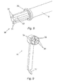
FIG. 8 presents a perspective view of a distal end of an elongated arm or the retractor;
FIG. 9 presents a perspective view of a socket of the paddle assembly configured to receive the distal end of FIG. 8;
FIG. 10 present a schematic representation of the circuit formed from when the socket of FIG. 9 receives the distal end of the elongated arm of FIG. 8;
FIG. 11 presents an exploded view of the locking mechanism of the retractor of FIG. 2;
FIG. 12 presents an exploded view and two operational views of a unidirectional clutch employed by the locking mechanism of FIG. 11;
FIG. 13 presents an exploded view of an alternative surgical retractor in accordance with an aspect of the present invention;
FIG. 14 presents a perspective view of the alternative surgical retractor of FIG. 13;
FIG. 15 presents a plan view of the alternative surgical retractor of FIG. 13 in:
    • (a) a closed position; and
    • (b) an open position; and
FIG. 16 presents a perspective view of a further alternative elongate arm similar to that illustrated in FIG. 13.
For consistency and clarity purposes the various features of the described retractors are referred to by the same reference numerals throughout the specification. Where appropriate, those reference numerals employed to describe the features common to alternative embodiments of the invention are also maintained within the specific description.
DETAILED DESCRIPTION
In order to assist understanding of the present invention, FIG. 2 presents various views of a surgical retractor 8 in accordance with an aspect of the present invention. In particular, FIG. 2 presents a perspective view, an exploded perspective view, a top view of a closed position and a top view of an open position of the retractor 8. The retractor 8 is again of a type comprising two elongated arms 9 mechanically connected by a pivot 10. At the distal end of each elongated arm 9 is located a paddle assembly 11, the separation of the paddle assemblies 11 being controlled through the manual manipulation of handles 12 located at the proximal end of the elongated arms 9, in conjunction with the operation of a locking mechanism 13 which moves between a closed and open position via the controlled operation of a lever 14, further detail of which is described below. From FIG. 2(b) it can be seen that the paddle assemblies 11 comprise independent units which snap fit onto the distal ends of the elongated arms 9, further detail of which is also provided below.
Detail of the components of the paddle assembly 11 can be seen from the exploded view presented within FIG. 3. The paddle assembly 11 comprises an hermetically sealed unit consisting of a first case section 15, a second case section 16 and a paddle 17 located between the first and second casing sections, 15 and 16, respectively. The hermetic seal of paddle assembly 11 is created by ultrasonic welding the first 15 and second casing sections 16. Such a process has the advantage of eliminating the need for any fixtures or sealing gaskets.
FIG. 4 presents a perspective view of the paddle 17 which can be seen to comprise a substantially planar first surface 18 and a curved second surface 19 arranged to project out of the plane of the first surface 18. Located one side of the first surface 18 are two elongated grooves or runners 20 which form an interference fit with two corresponding pips 21 located on an internal surface of the second casing section 16. As a result of this arrangement the protrusion of the paddle 17 from the casing can be quickly and easily adjusted so as to allow a surgeon to alter the size of the retractor 8 depending on the depth of the incision (or in other words the amount of skin, fat and muscle that has to be retracted). The interference fit between the pips 21 and the runners 20 is such that the paddle 17 can not fall out when the paddle assembly 11 is held vertically, but can be pulled out of, or pushed into the casing by the surgeon. In its fully retracted position, the paddle 17 is approximately 45 mm long, extending to approximately 80 mm in its fully extended configuration.
Further detail of the paddle assembly 11 can be seen from FIG. 5 within which is presented a perspective view of the paddle assembly with the first casing section 15 and the paddle 17 removed. Located within a cylindrical chamber 22 is a battery 23 employed to power illumination electronics 24 of the retractor 8.
A circuit diagram of the illumination electronics 24 is provided within FIG. 6. The illumination electronics 24 can be seen to comprise a printed circuit board (PCB) 25 upon which is located a driver 26 and an inductor 27 employed to regulate a current drawn from the battery 23 so as to power a white LED 28. In the presently described embodiment, the LED comprises a high powered Luxeon Rebel device, powered by a AAA battery. As a result the combined effect of the inductor 27 and the driver 26 is to provide a 50 mA current to the LED 28 thus providing approximately four hours worth of light generation.
The orientation of the LEDs 28 relative to the elongated arms 9 of the retractor 8 can be seen from the cross sectional end views of the paddle assemblies 11 presented within FIG. 7. The PCB 25 with associated LED 28 and illumination electronics 26 and 27 are mounted such that they are angled relative to the first surface 18 of the associated paddle 17 when both components are located within the paddle assembly 11. In practice, the LED 28 is mounted such that its normal 29 forms an acute angle relative to the substantially planer first surface 18 of the paddle 17. Accordingly, light generated by the LEDs 28 propagates in a generally downwards direction into the created working space when the retractor 8 is deployed by a surgeon. This has the effect of providing flood lighting to the working space formed within a patient.
It should be noted that the basic configuration of the paddle assemblies 11 allows for the working space to be fully illuminated without requiring the employment of any special lenses or further inserts. The overall effect is a general illumination of the working space, with the spread being defined by a particular type of LED employed.
A significant advantage of the presently described retractor 8 can be seen from an examination of FIGS. 8 to 10. FIG. 8 presents a perspective view of a distal end of an elongated arm 9 of the retractor 8, generally depicted by reference numeral 30. The distal end 30 can be seen to comprise four radially orientated guides 31, located at the centre of which is a conductive insert 32. At the proximal end of the four guides 31 is located an O-ring 33. The distal end therefore comprises a male plug for the elongated arm.
A corresponding female socket is located at one end of the cylindrical chamber 22. The female socket comprises four grooves 34, suitable for receiving the four guides 31 of the male plug, and two metal contacts 35 moulded within a central area of the female socket.
The incorporation of the male plug and the female socket provides a novel method for activating the LED 28, details of which can be seen from FIG. 10. In particular, FIG. 10 presents a schematic representation of a circuit formed when the paddle assembly 11 is snap-fitted onto an elongated arm 9. When the snap-fit action takes place, the conductive insert 32 completes a circuit comprising the battery 23, the LED 28 and the two metal contacts 35. This allows current to flow from the battery 23 to the LED 28, thus activating the generation of light. At the same time the O-ring 33 provides a seal for the respective paddle assembly 11.
One significant advantages of employing such a design within the retractor 8 is that it removes the requirement to have a dedicated on/off switch within the retractor 8. Not having such a switch improves the simplicity of the apparatus. It is known to those skilled in the art that on/off switches are historically difficult to seal since most switches involve a moving element that runs from outside, to inside, a casing which can lead to leak paths.
It will be readily apparent to those skilled in the art that alternative designs along a similar theme may be incorporated within the retractor 8. For example, the conductive insert could be replaced by a magnet such that it activates a reed switch located within the female socket when the paddle assembly 11 is snap-fitted onto the elongated arm 9. Such an embodiment would further reduce the risk of a leak path forming since no components would be required to run from inside, to outside, the casing.
In a further alternative embodiment, a flexible diaphragm maybe located within the female socket such that it is depressed when the male plug, located at the distal end 30 of the elongated arm 9, is snap-fitted into the socket. This would result in a sprung connector moving towards the battery 23, thus completing the circuit, as required.
A further advantage of the presently described retractor 8 resides in the locking mechanism 13 employed by the device, details of which is provided within FIGS. 11 and 12. In particular, FIG. 11 presents an exploded view of the locking mechanism 13 which can be seen to comprise lever 14, a ring like end 36 of which surrounds an unidirectional clutch 37. FIG. 12 presents an exploded view, and two operational views, of the unidirectional clutch 37.
The unidirectional clutch 37 is in the form of a wrap spring clutch, itself comprising a first 38 and second hub 39, about which is located a helical spring 40. The inner diameter of the spring 40 is such that it forms an interference fit with the outer diameter of the first 38 and second hubs 39. Positioned at one end of the spring 40 is a tang 41 which locates within a recess 42 formed within the ring like end 36 of the lever 14. As a result there exists direct mechanical communication between the lever 14 and the spring 40.
With the above described arrangement, any attempt to rotate either the first 38 or second hub 39, in the direction of the helix, forces the spring 40 to wrap down around the hubs 38 and 39 thus immediately preventing their relative rotation. However, rotation is possible if the hubs 38 and 39 are rotated in the direction opposite to the helix of the spring 40.
Within the locking mechanism 13 the spring 40 is configured such that when the retractor 8 is moved towards its open position, see FIG. 2(d), the hubs, 38 and 39, rotate in the opposite direction to the direction of the helix. As a result, the spring 40 does not prevent the opening of the retractor 8. However, the retractor 8 can not immediately be moved towards the closed position of FIG. 2(c) because to do so requires the hubs, 38 and 39, to rotate in the direction of the helix. When it is desired to close the retractor 8 the lever 14 is pulled by the surgeon towards the handle 12. This movement acts to rotate the spring 40 in the direction opposite to the helix so releasing the hubs 38 and 39 from the spring 40. As a result, the hubs, 38 and 39, are now free to rotate in the direction of the helix and so the retractor 8 can be moved to the closed position of FIG. 2(c).
The above described locking mechanism 13 provides the retractor 8 with a smooth acting, integrated indexing system, that is hidden from view of the surgeon and allows for a continuous number of paddle separation positions to be set.
It will be readily apparent that a number of alternative features may be employed within the retractor 8. For example, various alternative batteries may be employed within an appropriately sized chamber 22, e.g. “coin cell” batteries.
Similarly alternative coloured LEDs may also be employed. In a further alternative, the light source may be in the form of a thin panel, mounted on the external surface of the front casing section 15.
A yet further alternative embodiment would be for the retractor to comprise only one paddle assembly with an integrated light source. The second paddle assembly could either be fixed to one of the elongated arms or alternatively be snap fitted thereon in a similar manner to that previously described. It is recognised however that such embodiments would experience a reduced level of illumination of the working space.
The principle materials involved in the production of the retractor 8 is glass-filled nylon for all but the paddle assemblies 11. The paddle assemblies 11 are made from sparked translucent polycarbonates. These materials are employed primarily for their stiffness. However, the sparking of the polycarbonates provides them with a frosted effect which, to a large degree, acts to hide the contained electronics but allows for the generated light to propagate so illuminating the working space, as required.
The employment of such materials significantly reduces the costs involved in the production of the retractor 8, thus providing a rugged apparatus for a cost which makes it suitable for single use operation. As a result, the requirement for sterilisation of the device is removed following use since the retractor 8 is intended to be used for a single operation only.
The snap-fit activation of the LEDs 28 provides the retractor 8 with approximately four hours of illumination. This is found to be more than adequate for the majority of operations for which it would be deployed. A further advantage of employing LEDs 28 is that they generate effectively cold light which is a highly desirable feature of any retractor 8 employed within open surgery.
Finally, the incorporation of retractable paddles provides the retractor 8 with enhanced flexibility when compared with those retractors known in the prior art.
From the above description it can be seen that the retractor 8 is ideally suited to be provided within a sterile package. Once opened, the surgeon simply snap-fits the paddle assemblies 11 onto the end of the elongated arms 9, thus activating the light and commencing the lifetime of the device. The paddle length is then selected and the device deployed as appropriate. Following completion of the operation, or the loss of power from the battery 23, the retractor 8 is simply disposed of.
An alternative embodiment of the present invention is now described with further reference to FIGS. 13 to 16. FIGS. 13 and 14 show perspective views of the component parts of an alternative retractor 43. With particular reference to FIG. 13, an exploded view of a first elongate arm 44 of the retractor 43 is shown, and FIGS. 14 and 15 show the first elongate arm 44 in an assembled form and arranged with its corresponding second elongate arm 45 and ready for use as a retractor 43.
The arm 44 can be seen to comprise a top casing section 46 and a bottom casing section 47 which engage by way of a shaped groove 48 extending around a perimeter of the bottom casing section 47 and a corresponding ridge (not visible) extending around a perimeter of the top casing section 46.
A number of lateral struts 49 extend across the width of the arm 44 lending structural rigidity to the arm 44 as well as providing a means of arranging and locating internal components therein. For example, the two lowermost struts 49A incorporate semi-circular recesses 50 which accommodate a battery 51. Other struts (for example 49B) incorporate thinner channels 52 which accommodate and guide a conductive strip 53. Housing the battery 51 at this end of the elongate arm 44 makes the retractor 43 easier to handle.
The conductive strip 53 serves to conduct electricity from the battery 51 at one end of the arm 44 to a paddle 54 at the opposite end. A switch 55 is located at the battery end of the conductive strip 53 and allows a user to selectively illuminate light source 56 as and when required, typically when in use. The light source 56 comprises a frame 57 which is inserted into a corresponding recess 58 in the paddle 54, and a shaped transparent window 59 which permits light from the light source 56 to illuminate the surrounding area.
FIGS. 14 and 15 show the first elongate arm 44 assembled and connected to second elongate arm 45 at a hinge section 60 to form a retractor 43. Within the hinge section 60 is located a unidirectional clutch 37 as illustrated and exemplified with reference to FIGS. 11 and 12 above. FIG. 15(a) shows the retractor 43 in a closed position and FIG. 15(b) shows the retractor 43 in an open position such as that in which it will be used.
In an alternative embodiment, see the partial view in FIG. 16, the switch shown in FIG. 13 is replaced with a reed switch 61 which resides entirely within the casing. A magnet 62 may be placed on the outer surface of the casing in a position which holds the reed switch 61 open, and when the retractor 43 is to be used the magnet 62 is removed, causing the reed switch 61 to close thus switching on the light source within the paddle(s) 54. This embodiment has particular advantages, especially in terms of hygiene and sterilisation. As the switch mechanism (as well as any other electronics) can be entirely housed within the retractor casing, the retractor can be hermetically sealed. Thus, processes such as ethylene oxide (EO) sterilisation, which is a common way of sterilising medical supplies and implements, can be carried out on the retractor.
The foregoing description of the invention has been presented for the purpose of illustration and description, and is not intended to be exhaustive or to limit the invention to the precise form disclosed. The described embodiments were chosen and described in order to best explain the principals of the invention and its practical applications, to thereby enable others skilled in the art to best utilise the invention in various embodiments and with various modifications as are suited to the particular use upon completion. Therefore, further modifications and improvements may be incorporated without departing from the scope of the appended claims.

Claims (16)

The invention claimed is:
1. A retractor suitable for creating a working space for open surgery, the retractor comprising:
two elongated arms mechanically connected to each other by a pivot that allows the retractor to move between a closed and an open configuration;
each elongated arm comprising a paddle assembly located at a distal end, wherein
a first paddle assembly comprises a transparent window and forms a hermetically sealed housing for a first light source and a first power source for the first light source, the first light source being mounted within the first paddle assembly and configured to illuminate the working space.
2. A retractor as claimed in claim 1 further comprising a switch adapted to selectively illuminate the first light source.
3. A retractor as claimed in claim 2 wherein the switch comprises a non contact switching mechanism.
4. A retractor as claimed in claim 3 wherein the switching mechanism is located within the first paddle assembly.
5. A retractor as claimed in claim 2 wherein the switch comprises a reed switch adapted to open when a magnet is removed from proximity thereto.
6. A retractor as claimed in claim 1 wherein the first elongated arm comprises a plurality of struts arranged substantially transverse to a length of the first elongated arm.
7. A retractor as claimed in claim 1 wherein the first light source is mounted within the first paddle assembly such that a normal to the first light source forms an acute angle with a substantially planar first surface of the paddle assembly.
8. A retractor as claimed in claim 1 wherein the retractor further comprises a locking mechanism, the locking mechanism comprising a lever arranged to mechanically communicate with a unidirectional clutch arranged to prevent the retractor from moving towards the closed configuration.
9. A retractor as claimed in claim 8 wherein the unidirectional clutch comprises a wrap spring clutch.
10. A retractor as claimed in claim 1 wherein the retractor further comprises handles located at the proximal ends of the two elongated arms.
11. A retractor as claimed in claim 10 wherein the first and second handles comprise glass filled nylon.
12. A retractor as claimed in claim 1 wherein the two elongated arms comprise glass filled nylon.
13. A retractor as claimed claim 1 wherein the transparent window of the first paddle assembly comprises a sparked translucent polycarbonate.
14. A retractor as claimed in claim 1 wherein a second paddle assembly comprises a second transparent window and forms a second hermetically sealed housing for a second light source and a second power source for the second light source, the second light source being mounted within the second paddle assembly and configured to illuminate the working space.
15. A retractor as claimed in claim 1 wherein the light source is in the form of a panel.
16. A retractor suitable for creating a working space for open surgery, the retractor comprising:
two elongated arms mechanically connected to each other by a pivot that allows the retractor to move between a closed and an open configuration;
handles located at the proximal ends of the two elongated arms;
the two arms each comprising a paddle assembly located at a distal end, wherein
each paddle assembly comprises a transparent window and forms a hermetically sealed housing for a light source and a power source for the light source, the light sources being mounted within the respective paddle assemblies and configured to illuminate the working space.
US14/500,296 2007-09-19 2014-09-29 Retractor with integrated light source Expired - Fee Related US9339262B2 (en)

Priority Applications (1)

Application Number Priority Date Filing Date Title
US14/500,296 US9339262B2 (en) 2007-09-19 2014-09-29 Retractor with integrated light source

Applications Claiming Priority (5)

Application Number Priority Date Filing Date Title
GBGB0718268.6A GB0718268D0 (en) 2007-09-19 2007-09-19 Retractor with integrated light source
GB0718268.6 2007-09-19
PCT/GB2008/050786 WO2009037498A2 (en) 2007-09-19 2008-09-04 Retractor with integrated light source
US67906710A 2010-09-01 2010-09-01
US14/500,296 US9339262B2 (en) 2007-09-19 2014-09-29 Retractor with integrated light source

Related Parent Applications (2)

Application Number Title Priority Date Filing Date
PCT/GB2008/050786 Continuation WO2009037498A2 (en) 2007-09-19 2008-09-04 Retractor with integrated light source
US12/679,067 Continuation US8876713B2 (en) 2007-09-19 2008-09-04 Retractor with integrated light source

Publications (2)

Publication Number Publication Date
US20150045627A1 US20150045627A1 (en) 2015-02-12
US9339262B2 true US9339262B2 (en) 2016-05-17

Family

ID=39865841

Family Applications (2)

Application Number Title Priority Date Filing Date
US12/679,067 Expired - Fee Related US8876713B2 (en) 2007-09-19 2008-09-04 Retractor with integrated light source
US14/500,296 Expired - Fee Related US9339262B2 (en) 2007-09-19 2014-09-29 Retractor with integrated light source

Family Applications Before (1)

Application Number Title Priority Date Filing Date
US12/679,067 Expired - Fee Related US8876713B2 (en) 2007-09-19 2008-09-04 Retractor with integrated light source

Country Status (4)

Country Link
US (2) US8876713B2 (en)
EP (1) EP2187816A2 (en)
GB (1) GB0718268D0 (en)
WO (1) WO2009037498A2 (en)

Families Citing this family (26)

* Cited by examiner, † Cited by third party
Publication number Priority date Publication date Assignee Title
AU2007246162B2 (en) * 2006-04-27 2014-06-05 Colin Dunlop A light source apparatus
US9757109B2 (en) * 2010-12-10 2017-09-12 Illumix Surgical Canada Inc. Organic light emitting diode illuminated surgical retractor
US9592041B2 (en) * 2011-10-18 2017-03-14 Warsaw Orthopedic, Inc. Surgical retractor assembly and method
US8899809B2 (en) 2012-01-30 2014-12-02 Invuity, Inc. Illuminated clip and methods of use
US10835228B2 (en) * 2012-07-17 2020-11-17 Warsaw Orthopedic, Inc. Surgical retractor and method of use
ES2458394B1 (en) * 2012-10-30 2015-07-30 Servicio Andaluz De Salud IMPROVED FINOCHIETTO TYPE COSTAL SEPARATOR
WO2014072976A1 (en) * 2012-11-08 2014-05-15 Emodi Omri Intracavity illumination device
EP2981394B1 (en) 2013-04-01 2021-06-02 Vinod V. Pathy Lighting device
USD938095S1 (en) 2013-04-01 2021-12-07 Pathy Medical, Llc Lighting device
GB2532239A (en) * 2014-11-12 2016-05-18 Clear Surgical Ltd Retractor with improved light source, and light source for an improved retractor
US11672562B2 (en) 2015-09-04 2023-06-13 Medos International Sarl Multi-shield spinal access system
US11439380B2 (en) 2015-09-04 2022-09-13 Medos International Sarl Surgical instrument connectors and related methods
US11744447B2 (en) 2015-09-04 2023-09-05 Medos International Surgical visualization systems and related methods
CN113143355A (en) 2015-09-04 2021-07-23 美多斯国际有限公司 Multi-shield spinal access system
US10987129B2 (en) 2015-09-04 2021-04-27 Medos International Sarl Multi-shield spinal access system
US10092281B2 (en) 2015-10-06 2018-10-09 Inmotus Medical Llc Surgical retractor
TWI618551B (en) * 2016-03-28 2018-03-21 英濟股份有限公司 Expander
US11583660B2 (en) * 2016-10-12 2023-02-21 Susan Smith Female urethral catheterization assist device
WO2019051447A1 (en) * 2017-09-11 2019-03-14 Progressive Innovations, Llc Lighted specula, related kits, and methods for using the same
US11559372B2 (en) 2017-09-22 2023-01-24 Medos International Sarl Patient-mounted surgical retractor
AU2018335612B2 (en) 2017-09-22 2023-08-24 Medos International Sàrl Patient-mounted surgical support
JP7267264B2 (en) * 2017-09-22 2023-05-01 メドス・インターナショナル・エスエイアールエル patient-worn surgical retractor
USD884169S1 (en) * 2018-01-18 2020-05-12 Paragon 28, Inc. Clamp
US11204060B2 (en) 2019-11-27 2021-12-21 Medos International Sari Selectively lockable ball and socket joint
US11229464B2 (en) 2019-12-04 2022-01-25 Medos International Sarl Apparatus for driver-specific backout prevention
CN112336392A (en) * 2020-11-10 2021-02-09 徐树建 Opening device for thyroid surgery

Citations (39)

* Cited by examiner, † Cited by third party
Publication number Priority date Publication date Assignee Title
US3766910A (en) 1970-10-09 1973-10-23 P Lake Disposable delicate tissue retractor
GB1381387A (en) 1972-09-29 1975-01-22 Strad Instrumentation Ltd Cordless drill
US4226228A (en) 1978-11-02 1980-10-07 Shin Hee J Multiple joint retractor with light
US4502485A (en) 1977-06-30 1985-03-05 Burgin Kermit H Plastic forceps
US4562832A (en) 1984-01-21 1986-01-07 Wilder Joseph R Medical instrument and light pipe illumination assembly
US5005108A (en) 1989-02-10 1991-04-02 Lumitex, Inc. Thin panel illuminator
US5035232A (en) 1987-10-24 1991-07-30 Aesculap Ag Retractor
US5503617A (en) 1994-07-19 1996-04-02 Jako; Geza J. Retractor and method for direct access endoscopic surgery
US5569300A (en) 1995-04-12 1996-10-29 Redmon; Henry A. Dilating surgical forceps having illumination means on blade inner surface
US5871493A (en) 1995-10-31 1999-02-16 Smith & Nephew Endoscopy Inc. Surgical instrument handpiece and system
US5944736A (en) 1996-02-20 1999-08-31 Cardiothoracic Systems, Inc. Access platform for internal mammary dissection
US6080105A (en) 1997-06-26 2000-06-27 Spears; Robert A. Illuminated dental and surgical retractor and kit including plurality of blades and blades recharging base
US6185356B1 (en) 1995-06-27 2001-02-06 Lumitex, Inc. Protective cover for a lighting device
US6224545B1 (en) 1998-07-24 2001-05-01 Core Surgical, Inc. Surgical retractor and method for use
US6554768B1 (en) 2000-09-05 2003-04-29 Genzyme Corporation Illuminated deep pelvic retractor
US20030095781A1 (en) 1997-07-02 2003-05-22 Williams Jeffrey B. Illuminated surgical retractor
US20040024291A1 (en) 2002-08-01 2004-02-05 Zinkel John L. Method and apparatus for spinal surgery
DE202004005757U1 (en) 2004-04-13 2004-06-17 Lucchesi, Riccardo, Dr. Handling and / or processing device and surgical instrument
US20040242971A1 (en) 2002-01-23 2004-12-02 Holland Donna D. Illuminated retractor for use in connection with harvesting a blood vessel from the arm
US20050096646A1 (en) 2003-10-31 2005-05-05 Parris Wellman Surgical system for retracting and severing tissue
US20050154263A1 (en) 2004-01-13 2005-07-14 Nady Nady E. Device for spreading and holding open a body cavity
US20070060795A1 (en) 2005-09-14 2007-03-15 Spotlight Surgical, Inc. Lighted surgical retractors with LED illumination light engines
DE102006042985A1 (en) 2005-10-04 2007-04-19 Erbe Elektromedizin Gmbh Electrosurgical instrument for coagulating tissue, has deformable unit arranged on branch or gripping device such that area of gripping device can be moved to actuate switching device when branches are closed and minimum distance is reached
US20070244353A1 (en) 2006-04-13 2007-10-18 Larsen Dane M Resectoscopic Device And Method
US20070293729A1 (en) 2006-05-26 2007-12-20 Spotlight Surgical, Inc. Blade insert illuminator
US20080108877A1 (en) 2006-05-22 2008-05-08 Ardeshir Bayat Disposable expandable cordless lighted retractor
US20080114207A1 (en) 2006-11-14 2008-05-15 Krupa Robert J Portable endoscope
US20080234549A1 (en) 2007-03-22 2008-09-25 Vital Signs, Inc. Laryngoscope blade
US20080269565A1 (en) 2005-04-01 2008-10-30 Welch Allyn, Inc. Vaginal Speculum Apparatus
US20090018399A1 (en) 2004-10-08 2009-01-15 Scot Martinelli Surgical access system and related methods
US20090187078A1 (en) 2006-04-27 2009-07-23 Colin Dunlop Light source apparatus
US20110144439A1 (en) 2003-02-27 2011-06-16 Nuvasive, Inc. Surgical access system and related methods
US8088066B2 (en) 2007-10-24 2012-01-03 Invuity, Inc. Blade insert illuminator
US20120041268A1 (en) 2008-08-13 2012-02-16 Invuity, Inc. Cyclo olefin polymer and copolymer medical devices
US8137284B2 (en) 2002-10-08 2012-03-20 Nuvasive, Inc. Surgical access system and related methods
US20120116170A1 (en) 2010-10-08 2012-05-10 Invuity, Inc. Method and apparatus for soft tissue retraction
US20120149992A1 (en) 2010-12-10 2012-06-14 Anil Duggal Organic Light Emitting Diode Illuminated Surgical Retractor
US20120209080A1 (en) 2006-01-18 2012-08-16 Invuity, Inc. Retractor illumination system
US20120209076A2 (en) 2010-09-29 2012-08-16 Alfred E. Mann Institute For Biomedical Engineering At The University Of Southern California Minimally obstructive retractor

Patent Citations (46)

* Cited by examiner, † Cited by third party
Publication number Priority date Publication date Assignee Title
US3766910A (en) 1970-10-09 1973-10-23 P Lake Disposable delicate tissue retractor
GB1381387A (en) 1972-09-29 1975-01-22 Strad Instrumentation Ltd Cordless drill
US4502485A (en) 1977-06-30 1985-03-05 Burgin Kermit H Plastic forceps
US4226228A (en) 1978-11-02 1980-10-07 Shin Hee J Multiple joint retractor with light
US4562832A (en) 1984-01-21 1986-01-07 Wilder Joseph R Medical instrument and light pipe illumination assembly
US5035232A (en) 1987-10-24 1991-07-30 Aesculap Ag Retractor
US5005108A (en) 1989-02-10 1991-04-02 Lumitex, Inc. Thin panel illuminator
US5503617A (en) 1994-07-19 1996-04-02 Jako; Geza J. Retractor and method for direct access endoscopic surgery
US5569300A (en) 1995-04-12 1996-10-29 Redmon; Henry A. Dilating surgical forceps having illumination means on blade inner surface
US6185356B1 (en) 1995-06-27 2001-02-06 Lumitex, Inc. Protective cover for a lighting device
US6504985B2 (en) 1995-06-27 2003-01-07 Lumitex, Inc. Illuminated surgical retractor
US5871493A (en) 1995-10-31 1999-02-16 Smith & Nephew Endoscopy Inc. Surgical instrument handpiece and system
US20030060686A1 (en) 1996-02-20 2003-03-27 Taylor Charles S. Access platform for internal mammary dissection
US5944736A (en) 1996-02-20 1999-08-31 Cardiothoracic Systems, Inc. Access platform for internal mammary dissection
US6602189B1 (en) 1996-02-20 2003-08-05 Cardiothoracic Systems, Inc. Access platform for internal mammary dissection
US6080105A (en) 1997-06-26 2000-06-27 Spears; Robert A. Illuminated dental and surgical retractor and kit including plurality of blades and blades recharging base
US20060217596A1 (en) 1997-07-02 2006-09-28 Lumitex, Inc. Illuminated surgical retractor
US20030095781A1 (en) 1997-07-02 2003-05-22 Williams Jeffrey B. Illuminated surgical retractor
US6224545B1 (en) 1998-07-24 2001-05-01 Core Surgical, Inc. Surgical retractor and method for use
US6554768B1 (en) 2000-09-05 2003-04-29 Genzyme Corporation Illuminated deep pelvic retractor
US20040242971A1 (en) 2002-01-23 2004-12-02 Holland Donna D. Illuminated retractor for use in connection with harvesting a blood vessel from the arm
US20040024291A1 (en) 2002-08-01 2004-02-05 Zinkel John L. Method and apparatus for spinal surgery
US20120238822A1 (en) 2002-10-08 2012-09-20 Nuvasive, Inc. Surgical access system and related methods
US8137284B2 (en) 2002-10-08 2012-03-20 Nuvasive, Inc. Surgical access system and related methods
US20110144439A1 (en) 2003-02-27 2011-06-16 Nuvasive, Inc. Surgical access system and related methods
US20050096646A1 (en) 2003-10-31 2005-05-05 Parris Wellman Surgical system for retracting and severing tissue
US20050154263A1 (en) 2004-01-13 2005-07-14 Nady Nady E. Device for spreading and holding open a body cavity
WO2005102177A1 (en) 2004-04-13 2005-11-03 Riccardo Lucchesi Manipulation and/or treatment device and surgical instrument
DE202004005757U1 (en) 2004-04-13 2004-06-17 Lucchesi, Riccardo, Dr. Handling and / or processing device and surgical instrument
US20090018399A1 (en) 2004-10-08 2009-01-15 Scot Martinelli Surgical access system and related methods
US8435175B2 (en) 2005-04-01 2013-05-07 Welch Allyn, Inc. Vaginal speculum apparatus
US20080269565A1 (en) 2005-04-01 2008-10-30 Welch Allyn, Inc. Vaginal Speculum Apparatus
US20070060795A1 (en) 2005-09-14 2007-03-15 Spotlight Surgical, Inc. Lighted surgical retractors with LED illumination light engines
DE102006042985A1 (en) 2005-10-04 2007-04-19 Erbe Elektromedizin Gmbh Electrosurgical instrument for coagulating tissue, has deformable unit arranged on branch or gripping device such that area of gripping device can be moved to actuate switching device when branches are closed and minimum distance is reached
US20120209080A1 (en) 2006-01-18 2012-08-16 Invuity, Inc. Retractor illumination system
US20070244353A1 (en) 2006-04-13 2007-10-18 Larsen Dane M Resectoscopic Device And Method
US20090187078A1 (en) 2006-04-27 2009-07-23 Colin Dunlop Light source apparatus
US20080108877A1 (en) 2006-05-22 2008-05-08 Ardeshir Bayat Disposable expandable cordless lighted retractor
US20070293729A1 (en) 2006-05-26 2007-12-20 Spotlight Surgical, Inc. Blade insert illuminator
US20080114207A1 (en) 2006-11-14 2008-05-15 Krupa Robert J Portable endoscope
US20080234549A1 (en) 2007-03-22 2008-09-25 Vital Signs, Inc. Laryngoscope blade
US8088066B2 (en) 2007-10-24 2012-01-03 Invuity, Inc. Blade insert illuminator
US20120041268A1 (en) 2008-08-13 2012-02-16 Invuity, Inc. Cyclo olefin polymer and copolymer medical devices
US20120209076A2 (en) 2010-09-29 2012-08-16 Alfred E. Mann Institute For Biomedical Engineering At The University Of Southern California Minimally obstructive retractor
US20120116170A1 (en) 2010-10-08 2012-05-10 Invuity, Inc. Method and apparatus for soft tissue retraction
US20120149992A1 (en) 2010-12-10 2012-06-14 Anil Duggal Organic Light Emitting Diode Illuminated Surgical Retractor

Also Published As

Publication number Publication date
US20100317928A1 (en) 2010-12-16
US8876713B2 (en) 2014-11-04
WO2009037498A2 (en) 2009-03-26
US20150045627A1 (en) 2015-02-12
GB0718268D0 (en) 2008-10-08
EP2187816A2 (en) 2010-05-26
WO2009037498A3 (en) 2009-05-07

Similar Documents

Publication Publication Date Title
US9339262B2 (en) Retractor with integrated light source
US20130331657A1 (en) Self-powered lighting system for use with an electrosurgical pencil
US20180318034A1 (en) Devices and kits for assisting in open surgeries
EP2117457B1 (en) Attachable portable illumination apparatus for surgical instruments
JP5181191B2 (en) Speculum
CH701320B1 (en) A device for resection treatments / endoscopic tissue removal.
WO1998025512A1 (en) Light and handle device for vaginal speculum
CN107613843B (en) Lighting device
EP3515324B1 (en) Robotic surgical system
US9072541B2 (en) Surgical scalpel handle with illuminator
US10426567B2 (en) Retractor with improved light source, and light source for an improved retractor
EP4013313A1 (en) Retraction device for breast surgery
US11083445B2 (en) Knife and retractor system
RU205813U1 (en) Retractor with LED illuminator on the flexible-elastic working part of the tool
RU48747U1 (en) Backlight tweezers
JP7209976B2 (en) Irradiation equipment for endoscopic surgery
RU183801U1 (en) SCALPEL
US20200275831A1 (en) Lighted specula, related kits, and methods for using the same
KR20110083836A (en) Clip type led lights for surgical retractor
KR20050116337A (en) Penlight

Legal Events

Date Code Title Description
AS Assignment

Owner name: AYRSHIRE AND ARRAN HEALTH BOARD, UNITED KINGDOM

Free format text: ASSIGNMENT OF ASSIGNORS INTEREST;ASSIGNOR:SUBRAMANIAM, MURALI;REEL/FRAME:033863/0617

Effective date: 20100610

Owner name: CLEAR SURGICAL LIMITED, UNITED KINGDOM

Free format text: ASSIGNMENT OF ASSIGNORS INTEREST;ASSIGNOR:AYRSHIRE AND ARRAN HEALTH BOARD;REEL/FRAME:033863/0736

Effective date: 20130731

STCF Information on status: patent grant

Free format text: PATENTED CASE

FEPP Fee payment procedure

Free format text: MAINTENANCE FEE REMINDER MAILED (ORIGINAL EVENT CODE: REM.); ENTITY STATUS OF PATENT OWNER: SMALL ENTITY

LAPS Lapse for failure to pay maintenance fees

Free format text: PATENT EXPIRED FOR FAILURE TO PAY MAINTENANCE FEES (ORIGINAL EVENT CODE: EXP.); ENTITY STATUS OF PATENT OWNER: SMALL ENTITY

STCH Information on status: patent discontinuation

Free format text: PATENT EXPIRED DUE TO NONPAYMENT OF MAINTENANCE FEES UNDER 37 CFR 1.362